


Evolution of OAI Software towards 5G NR2018.wons-conference.org/docs/knopp_5G-day5.pdf · Evolution...
66
Evolution of OAI Software towards 5G NR Raymond Knopp Communication Systems Department EURECOM Unleashing the potential of open-source in the 5G arena
Transcript of Evolution of OAI Software towards 5G NR2018.wons-conference.org/docs/knopp_5G-day5.pdf · Evolution...

Evolution of OAI Software towards 5G NR
Raymond Knopp
Communication Systems Department
EURECOM
Unleashing the potential of open-source in the 5G arena

Outline
Overview of 5G NR Network Evolution
(very quick) Overview of Current 5G NR Air interface specifications
Evolution of OAI to handle 5G NR and CN
Towards NR in OAI

Key RAN specifications (L2)
3GPP TS 23.501: "System Architecture for the 5G System; Stage 2".
3GPP TS 38.401: "NG-RAN; Architecture description".
3GPP TS 33.501: "Security Architecture and Procedures for 5G System".
3GPP TS 37.340: "NR; Multi-connectivity; Overall description; Stage-2".
3GPP TS 38.321: "NR; Medium Access Control (MAC) protocol specification".
3GPP TS 38.322: "NR; Radio Link Control (RLC) protocol specification".
3GPP TS 38.323: "NR; Packet Data Convergence Protocol (PDCP) specification".
3GPP TS 37.324: "NR; Service Data Protocol (SDAP) specification".
3GPP TS 38.304: "NR; User Equipment (UE) procedures in idle mode".
3GPP TS 38.306: "NR; User Equipment (UE) radio access capabilities".
3GPP TS 38.331: "NR; Radio Resource Control (RRC); Protocol specification".
3GPP TS 38.133: "NR; Requirements for support of radio resource management".
Towards NR in OAI

Overall Architecture
Towards NR in OAI
gNB
ng-eNB
NG
NG NG
Xn
NG-RAN
5GC
AMF/UPF
gNB
ng-eNB
NG
NG NG
Xn
AMF/UPF
Xn
Xn
NG NG

Functional Split between RAN and 5G Core
Towards NR in OAI
internet
gNB or ng-eNB
RB Control
Connection Mobility Cont.
MeasurementConfiguration & Provision
Dynamic Resource Allocation (Scheduler)
AMF
UPF
Inter Cell RRM
Radio Admission Control
NG-RAN 5GC
Mobility Anchoring
Idle State Mobility Handling
NAS Security
SMF
UE IP address allocation
PDU Session Control
PDU Handling

Functional Split (gNB, ng-eNB)
The gNB and ng-eNB host the following functions: – Functions for Radio Resource Management: Radio Bearer Control, Radio Admission Control, Connection
Mobility Control, Dynamic allocation of resources to UEs in both uplink and downlink (scheduling); – IP header compression, encryption and integrity protection of data; – Selection of an AMF at UE attachment when no routing to an AMF can be determined from the information
provided by the UE; – Routing of User Plane data towards UPF(s); – Routing of Control Plane information towards AMF; – Connection setup and release; – Scheduling and transmission of paging messages (originated from the AMF); – Scheduling and transmission of system broadcast information (originated from the AMF or
O&M);Measurement and measurement reporting configuration for mobility and scheduling; – Transport level packet marking in the uplink; – Session Management; – Support of Network Slicing; – QoS Flow management and mapping to data radio bearers; – Support of UEs in RRC_INACTIVE state; – Distribution function for NAS messages; – Radio access network sharing; – Dual Connectivity; – Tight interworking between NR and E-UTRA.
Towards NR in OAI

Functional Split (AMF)
The AMF hosts the following main functions (see 3GPP TS 23.501): – NAS signalling termination; – NAS signalling security; – AS Security control; – Inter CN node signalling for mobility between 3GPP access networks; – Idle mode UE Reachability (including control and execution of paging
retransmission); – Registration Area management; – Support of intra-system and inter-system mobility; – Access Authentication; – Access Authorization including check of roaming rights; – Mobility management control (subscription and policies); – Support of Network Slicing; – SMF selection.
Towards NR in OAI

Functional Split (UPF)
The UPF hosts the following main functions (see 3GPP TS 23.501): – Anchor point for Intra-/Inter-RAT mobility (when applicable); – External PDU session point of interconnect to Data Network; – Packet routing & forwarding; – Packet inspection and User plane part of Policy rule enforcement; – Traffic usage reporting; – Uplink classifier to support routing traffic flows to a data network; – Branching point to support multi-homed PDU session; – QoS handling for user plane, e.g. packet filtering, gating, UL/DL rate
enforcement; – Uplink Traffic verification (SDF to QoS flow mapping); – Downlink packet buffering and downlink data notification triggering.
Towards NR in OAI

Functional Split (SPF)
The Session Management function (SMF) hosts the following main functions (see 3GPP TS 23.501): – Session Management; – UE IP address allocation and management; – Selection and control of UP function; – Configures traffic steering at UPF to route traffic to proper
destination; – Control part of policy enforcement and QoS; – Downlink Data Notification.
Towards NR in OAI

NG-C Interface
NG-C provides the following functions: – NG interface management; – UE context management; – UE mobility management; – Transport of NAS
messages; – Paging; – PDU Session
Management; – Configuration Transfer; – Warning Message
Transmission.
Towards NR in OAI
SCTP
IP
Data link layer
NG-AP
Physical layer

NG-U Interface
NG-U provides non-guaranteed delivery of user plane PDUs between the NG-RAN node and the UPF.
Towards NR in OAI
GTP-U
UDP
IP
Data link layer
User plane PDUs
Physical layer

Xn-C Interface
The Xn-C interface supports the following functions: – Xn interface management; – UE mobility management,
including context transfer and RAN paging:
– Dual connectivity;
Towards NR in OAI
SCTP
IP
Data link layer
Xn-AP
Physical layer

Xn-U Interface
Xn-U provides non-guaranteed delivery of user plane PDUs and supports the following functions: – Data forwarding; – Flow control.
Towards NR in OAI
GTP-U
UDP
IP
Data link layer
User plane PDUs
Physical layer

Radio Protocol
Towards NR in OAI
gNB
PHY
UE
PHY
MAC
RLC
MAC
PDCPPDCP
RLC
SDAPSDAP
gNB
PHY
UE
PHY
MAC
RLC
MAC
AMF
RLC
NAS NAS
RRC RRC
PDCP PDCP
MgNB
PDCP
RLC
SgNB
PDCP
RLC
Xn
RLC
MAC MAC
MCG Bearer
MCGSplit
Bearer
SDAP SDAP
SgNB
PDCP
RLC
MgNB
PDCP
RLC
Xn
RLC
MACMAC
SCGSplit
Bearer
SCGBearer
SDAP SDAP

Layer 2 Architecture (Downlink)
Towards NR in OAI
Segm.ARQ
Multiplexing UE1
Segm.ARQ...
HARQ
Multiplexing UEn
HARQ
Scheduling / Priority Handling
Logical Channels
Transport Channels
MAC
RLC Segm.ARQ
Segm.ARQ
PDCPROHC ROHC ROHC ROHC
Radio Bearers
Security Security Security Security
...
RLC Channels
SDAP QoS flowhandling
QoS Flows
QoS flowhandling

Layer 2 (Uplink)
Towards NR in OAI
Multiplexing
...
HARQ
Scheduling
Transport Channels
MAC
RLC
PDCP
Segm.ARQ
Segm.ARQ
Logical Channels
RLC Channels
ROHC ROHC
Radio Bearers
Security Security
SDAP
QoS Flows
QoS flowhandling

MAC Layer
The main services and functions of the MAC sublayer include: – Mapping between logical channels and transport channels; – Multiplexing/demultiplexing of MAC SDUs belonging to one or
different logical channels into/from transport blocks (TB) delivered to/from the physical layer on transport channels;
– Scheduling information reporting; – Error correction through HARQ (one HARQ entity per carrier in
case of CA); – Priority handling between UEs by means of dynamic scheduling; – Priority handling between logical channels of one UE by means
of logical channel prioritisation; – Padding.
Towards NR in OAI

Logical Channels
Broadcast Control Channel (BCCH): a downlink channel for broadcasting system control information.
Paging Control Channel (PCCH): a downlink channel that transfers paging information and system information change notifications.
Common Control Channel (CCCH): channel for transmitting control information between UEs and network. This channel is used for UEs having no RRC connection with the network.
Dedicated Control Channel (DCCH): a point-to-point bi-directional channel that transmits dedicated control information between a UE and the network. Used by UEs having an RRC connection.
Traffic channels are used for the transfer of user plane information only:
Dedicated Traffic Channel (DTCH): point-to-point channel, dedicated to one UE, for the transfer of user information. A DTCH can exist in both uplink and downlink.
Towards NR in OAI

Mapping of Logical to Physical Channels
In Downlink, the following connections between logical channels and transport channels exist: – BCCH can be mapped to BCH; – BCCH can be mapped to DL-SCH; – PCCH can be mapped to PCH; – CCCH can be mapped to DL-SCH; – DCCH can be mapped to DL-SCH; – DTCH can be mapped to DL-SCH.
In Uplink, the following connections between logical channels and transport channels exist: – CCCH can be mapped to UL-SCH; – DCCH can be mapped to UL- SCH; – DTCH can be mapped to UL-SCH.
Towards NR in OAI

RLC
The RLC sublayer supports three transmission modes: – Transparent Mode (TM); – Unacknowledged Mode (UM); – Acknowledged Mode (AM).
The main services and functions of the RLC sublayer depend on the transmission mode and include: – Transfer of upper layer PDUs; – Sequence numbering independent of the one in PDCP (UM and AM); – Error Correction through ARQ (AM only); – Segmentation (AM and UM) and re-segmentation (AM only) of RLC SDUs; – Reassembly of SDU (AM and UM); – Duplicate Detection (AM only); – RLC SDU discard (AM and UM); – RLC re-establishment; – Protocol error detection (AM only).
Towards NR in OAI

PDCP
The main services and functions of the PDCP sublayer for the user plane include:
– Sequence Numbering; – Header compression and decompression: ROHC only; – Transfer of user data; – Reordering and duplicate detection; – PDCP PDU routing (in case of split bearers); – Retransmission of PDCP SDUs; – Ciphering, deciphering and integrity protection; – PDCP SDU discard; – PDCP re-establishment and data recovery for RLC AM; – Duplication of PDCP PDUs.
The main services and functions of the PDCP sublayer for the control plane include:
– Sequence Numbering; – Ciphering, deciphering and integrity protection; – Transfer of control plane data; – Reordering and duplicate detection; – Duplication of PDCP PDUs (see subclause 16.1.3).
Towards NR in OAI

SDAP (Service Data Adaptation Protocol)
New entity w.r.t. 4G
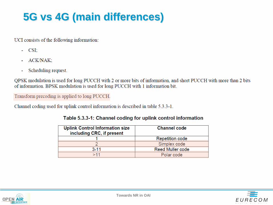
The main services and functions of SDAP include: – Mapping between a QoS flow and a data radio bearer; – Marking QoS flow ID (QFI) in both DL and UL packets.
Towards NR in OAI
Example L2 Data Flow
Towards NR in OAI
RByRBx
IP Packet
H SDAP SDU
PDCP SDUH
RLC SDUH
MAC SDUH H
IP Packet
H SDAP SDU
PDCP SDUH
RLC SDUH
MAC SDU
IP Packet
H SDAP SDU
PDCP SDUH
SDU SegmentH
MAC SDU
SDU SegmentH
H H MAC SDU
...
...
...
...
MAC PDU – Transport Block
PDCP
RLC
SDAP
MAC
n n+1 m
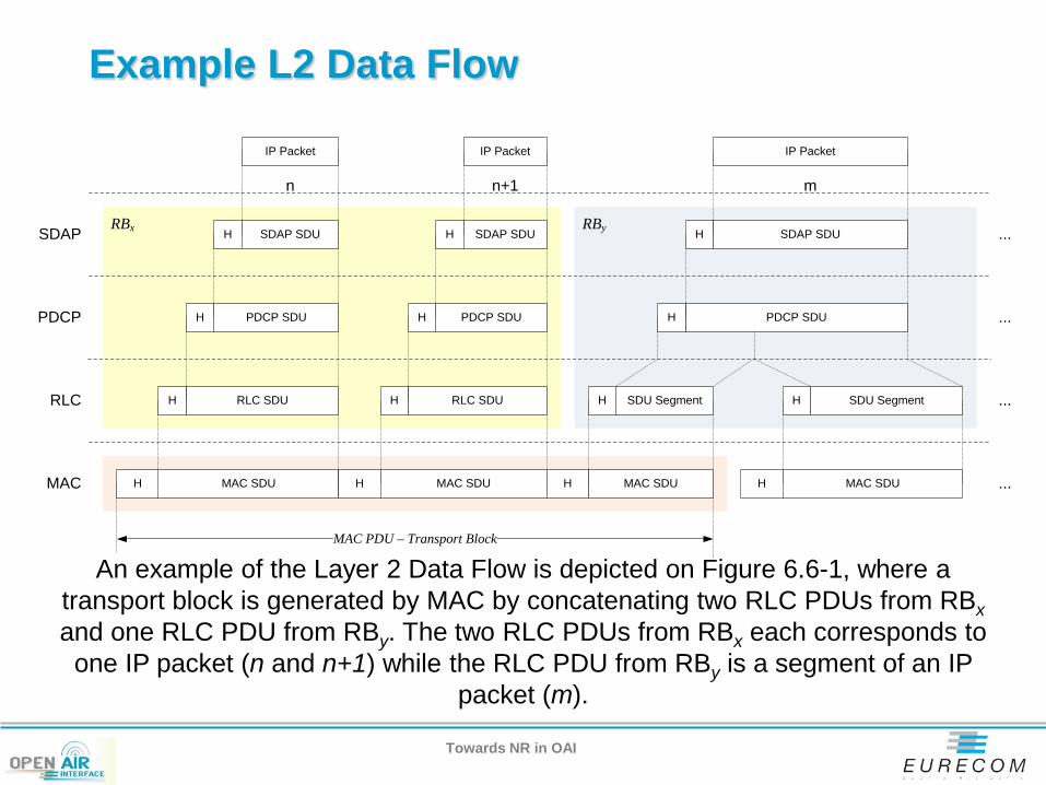
An example of the Layer 2 Data Flow is depicted on Figure 6.6-1, where a transport block is generated by MAC by concatenating two RLC PDUs from RBx and one RLC PDU from RBy. The two RLC PDUs from RBx each corresponds to one IP packet (n and n+1) while the RLC PDU from RBy is a segment of an IP
packet (m).

RRC
The main services and functions of the RRC sublayer include: – Broadcast of System Information related to AS and NAS; – Paging initiated by 5GC or NG-RAN; – Establishment, maintenance and release of an RRC connection between the UE
and NG-RAN including: Addition, modification and release of carrier aggregation; Addition, modification and release of Dual Connectivity in NR or between E-
UTRA and NR. – Security functions including key management; – Establishment, configuration, maintenance and release of Signalling Radio
Bearers (SRBs) and Data Radio Bearers (DRBs); – Mobility functions including:
Handover and context transfer; UE cell selection and reselection and control of cell selection and
reselection; Inter-RAT mobility.
– QoS management functions; – UE measurement reporting and control of the reporting; – Detection of and recovery from radio link failure; – NAS message transfer to/from NAS from/to UE.
Towards NR in OAI

New RRC States
RRC supports the following states which can be characterised as follows: – RRC_IDLE:
PLMN selection; Broadcast of system information; Cell re-selection mobility; Paging for mobile terminated data is initiated by 5GC; Paging for mobile terminated data area is managed by 5GC; DRX for CN paging configured by NAS.
– RRC_INACTIVE: Broadcast of system information; Cell re-selection mobility; Paging is initiated by NG-RAN (RAN paging); RAN-based notification area (RNA) is managed by NG- RAN; DRX for RAN paging configured by NG-RAN; 5GC - NG-RAN connection (both C/U-planes) is established for UE; The UE AS context is stored in NG-RAN and the UE; NG-RAN knows the RNA which the UE belongs to.
– RRC_CONNECTED: 5GC - NG-RAN connection (both C/U-planes) is established for UE; The UE AS context is stored in NG-RAN and the UE; NG-RAN knows the cell which the UE belongs to; Transfer of unicast data to/from the UE; Network controlled mobility including measurements.
Towards NR in OAI

UE Identities
For NR connected to 5GC, the following UE identities are used at cell level: – C-RNTI: unique identification, which is used as an identifier of the
RRC Connection and for scheduling; – Temporary C-RNTI: identification used for the random access
procedure; – Random value for contention resolution: during some transient
states, the UE is temporarily identified with a random value used for contention resolution purposes.
In DC, two C-RNTIs are independently allocated to the UE: one for MCG, and one for SCG.
For NR connected to 5GC, the following UE identities are used at NG-RAN level: – I-RNTI: unique identification used to identify the UE context for
RRC_INACTIVE.
Towards NR in OAI

Network Identities
The following identities are used in NG-RAN for identifying a specific network entity: – AMF Identifier: used to identify an AMF. – NR Cell Global Identifier (NCGI): used to identify NR cells globally.
The NCGI is constructed from the PLMN identity the cell belongs to and the NR Cell Identity (NCI) of the cell.
– gNB Identifier (gNB ID): used to identify gNBs within a PLMN. The gNB ID is contained within the NCI of its cells.
– Global gNB ID: used to identify gNBs globally. The Global gNB ID is constructed from the PLMN identity the gNB belongs to and the gNB ID. The MCC and MNC are the same as included in the NCGI.
– Tracking Area identity (TAI): used to identify tracking areas. The TAI is constructed from the PLMN identity the tracking area belongs to and the TAC (Tracking Area Code) of the Tracking Area.
– Single Network Slice Selection Assistance information (S-NSSAI): identifies a network slice.
Towards NR in OAI

UE triggered transition from RRC_INACTIVE to RRC_CONNECTED
Towards NR in OAI
gNB Last Serving gNB AMF
6. PATH SWITCH REQUEST
8. UE CONTEXT RELEASE
3. RETRIEVE UE CONTEXT RESPONSE
2. RETRIEVE UE CONTEXT REQUEST
7. PATH SWITCH REQUEST RESPONSE
UE
4. RRCConnectionResume
UE in RRC_INACTIVE / CM-CONNECTED
1. RRCConnectionResumeRequest
UE in RRC_CONNECTED / CM-CONNECTED
5. DATA FORWARDING ADDRESS INDICATION
1. The UE resumes from RRC_INACTIVE, providing the I-RNTI, allocated by the last serving gNB. 2. The gNB, if able to resolve the gNB identity contained in the I-RNTI, requests the last serving gNB to provide UE Context data. 3. The last serving gNB provides UE context data. 4. The gNB completes the resumption of the RRC connection. 5. If loss of DL user data buffered in the last serving gNB shall be prevented, the gNB provides forwarding addresses. 6./7. The gNB performs path switch. 8. The gNB triggers the release of the UE resources at the last serving gNB.

Network triggered transition from RRC_INACTIVE to RRC_CONNECTED
Towards NR in OAI
Last serving gNB gNB AMF
2. RAN Paging
UE
UE in RRC_INACTIVE / CM-CONNECTED
1. RAN Paging trigger
4. Resuming from RRC_INACTIVE
3. Paging the UE (Editor’s Note: details FFS)
1. A RAN paging trigger event occurs (incoming DL user plane, DL signalling from 5GC, etc.) 2. RAN paging is triggered; either only in the cells controlled by the last serving gNB or also by means of Xn RAN Paging, in other gNBs, being member of the RAN Paging area the UE is registered with. 3. The UE is paged with an NG-RAN allocated UE identity. Details are FFS. 4. If the UE has been successfully reached, it attempts to resume from RRC_INACTIVE, as described in other sections.

Mobility in RRC Connected
Towards NR in OAI
Target gNB
4. Handover Complete
Source gNB
AdmissionControl
2. Handover Acknowledgement3. Handover Command
UE
Switch to New Cell
1. Handover Request
1. The source gNB initiates handover and issues a Handover Request over the Xn interface. 2. The target gNB performs admission control and provides the RRC configuration as part of the Handover Acknowledgement. 3. The source gNB provides the RRC configuration to the UE in the Handover Command. The Handover Command message includes at least cell ID and all information required to access the target cell so that the UE can access the target cell without reading system information. For some cases, the information required for contention based and contention free random access can be included in the Handover Command message. The access information to the target cell may include beam specific information, if any. 4. The UE moves the RRC connection to the target gNB and replies the Handover Complete.

Measurements
Towards NR in OAI
gNB beam 1gNB beam 2
gNB beam K
Layer 3 filtering for cell
quality
Evaluation of reporting
criteria
Layer1 filteringLayer1 filtering
Layer1 filtering
Beam Consolidation/
Selection Cell quality
RRC configures parameters
RRC configures parameters
RRC configures parameters
UE Implementation specific
UE Implementation specific
B
A A1
CD
C1
L3 Beam filteringL3 Beam filtering
L3 Beam filtering
RRC configures parameters
K beams X beams Beam Selection
for reporting
K beams
E F
RRC configures parameters
In RRC_CONNECTED, the UE measures multiple beams (at least one) of a cell and the measurements results (power values) are averaged to derive the cell quality. In doing so, the UE is configured to consider a subset of the detected beams: the N best beams above an absolute threshold. Filtering takes place at two different levels: at the physical layer to derive beam quality and then at RRC level to derive cell quality from multiple beams. Cell quality from beam measurements is derived in the same way for the serving cell(s) and for the non-serving cell(s). Measurement reports may contain the measurement results of the X best beams if the UE is configured to do so by the gNB.

Paging
The UE in RRC_IDLE and RRC_INACTIVE states may use DRX in order to reduce power consumption. While in RRC_IDLE the UE monitors 5GC-initiated paging, in RRC_INACTIVE the UE is reachable via RAN-initiated paging and 5GC-initiated paging. RAN and 5GC paging occasions overlap and same paging mechanism is used. The UE monitors one paging occasion per DRX cycle for the reception of paging as follows:
Paging DRX cycle length is configurable: – A default DRX cycle for CN paging is configurable via system information; – A UE specific DRX cycle for CN paging is configurable via UE dedicated signalling; – NG-RAN can configure a UE with a DRX cycle for RAN paging. This configuration can be
UE specific.
The number of paging occasions in a DRX cycle is configurable via system information:
– A network may distribute UEs to the paging occasions based on UE id when multiple paging occasions are configured in the DRX cycle.
Paging occasion can consist of multiple time slots (e.g. subframe or OFDM symbol). The number of time slots in a paging occasion is configurable via system information:
– A network may transmit a paging using a different set of DL Tx beam(s) or repetitions in each time slot.
Towards NR in OAI

QoS
The QoS architecture in NG-RAN, both for NR connected to 5GC and for E-UTRA connected to 5GC, is depicted in the Figure 12-1 and described in the following: – For each UE, 5GC establishes one or more PDU Sessions. – For each UE, the NG-RAN establishes one or more Data Radio
Bearers (DRB) per PDU Session. The NG-RAN maps packets belonging to different PDU sessions to different DRBs. Hence, the NG-RAN establishes at least one default DRB for each PDU Session.
– NAS level packet filters in the UE and in the 5GC associate UL and DL packets with QoS Flows.
– AS-level mapping rules in the UE and in the NG-RAN associate UL and DL QoS Flows with DRBs.
Towards NR in OAI

QoS
Towards NR in OAI
UPFNBUE
PDU Session
Radio NG-U
NG-RAN 5GC
Radio Bearer NG-U TunnelQoS Flow
QoS Flow
Radio BearerQoS Flow

NG-RAN Functional Split
Towards NR in OAI
5GC
NG NG
Xn-C
NG-RAN
gNB
gNB-DU gNB-DU
gNB-CU
gNB
F1 F1

UE Initial Access
Towards NR in OAI
UE gNB-DU gNB-CU
1.RRC Connection Request
4.RRC Connection Setup
5.RRC Connection Setup Complete
2.Initial UL RRC message
AMF
7.Initial UE message
8.Initial UE Context Setup request
3. DL RRC message transfer
15.RRC Connection Reconfiguration
11.UE Context Setup Response
16.RRC Connection Reconfiguration Complete
18.Initial UE Context Setup Response
6.UL RRC Message Transfer
14.DL RRC Message Transfer
17.UL RRC Message Transfer
10.RRC Security Mode Command
12.RRC Security Mode Complete
9.UE Context Setup Request
13.UL RRC Message Transfer
gNB

UE Initial Access
Step1: UE sends RRC Connection Request message to the gNB-CU.
Step 2:The gNB-DU includes the RRC message in a non-UE associated F1-AP INITIAL UL RRC MESSAGE TRANSFER message and transfer to the gNB-CU. The INITAIL UL RRC MESSAGE TRANSFER message should include C-RNTI.
Step3: The gNB-CU allocates UE F1AP ID for the UE and generates RRC CONNECTION SETUP message towards UE.The RRC message is encapsulated in F1-AP DL RRC MESSAGE TRANSFER message.
Step4: The gNB-DU sends RRC CONNECTION SETUP message to UE.
Step5: UE sends RRC CONNECTION SETUP COMPLETE message to the gNB-CU.
Step6: The gNB-DU encapsulates the RRC message in F1-AP UL RRC MESSAGE TRANSFER message and send to gNB-CU.
Step7: The gNB-CU sends the INITIAL UE MESSAGE to the AMF.
Step8: The AMF sends INITIAL UE CONTEXT SETUP REQUEST message to the gNB-CU.
Step9:The gNB-CU sends UE CONTEXT SETUP REQUESTmessage to establish overall initial UE context in the gNB-DU.In this message,it may also encapsulate RRC SECURITY MODE COMMAND message.
Step10: The gNB-DU sends RRC SECURITY MODE COMMAND message to UE.
Step11:The gNB-DU sends UE CONTEXT SETUP RESPONSE message to gNB-CU.
Step 12:UE responds with RRC SECURITY MODE COMPLETE message
Step 13:The gNB-DU encapsulates the RRC message in F1-AP UL RRC MESSAGE TRANSFER message and sends to gNB-CU.
Step14:The gNB-CU generates RRC CONNECTION RECONFIGURATION message and encapsulates it in F1-AP DL RRC MESSAGE TRANSFER message
Step 15: The gNB-DU sends RRC CONNECTION RECONFIGURATION message to UE.
Step 16: UE sends RRC CONNECTION RECONFIGURATION COMPLETE message to the gNB-DU.
Step 17:The gNB-DU encapsulates the RRC message in F1-AP UL RRC MESSAGE TRANSFER message and send to gNB-CU.
Step18: The gNB-CU sends Initial UE Context Setup Response message to the AMF.
Towards NR in OAI

Inter-gNB-DU Mobility for intra-NR
Towards NR in OAI
UE SourcegNB-DU
TargetgNB-DU gNB-CU
1. Measurement Report
2. Uplink RRC Transfer(Measurement Report)
3. UE Context Setup Request
4. UE Context Setup Response
5. UE Mobility Command(RRCConnectionReconfiguration)
9. RRCConnectionReconfigurationComplete
6. RRCConnectionReconfiguration
10. Uplink RRC Transfer(RRCConnectionReconfigurationComplete)
8. Random Access Procedure
11. UE Context Release Command
12. UE Context Release Complete
Downlink user data
Uplink user data
Downlink Data Delivery Status
Downlink user data
Downlink user data
Uplink user data
7. UE Mobility Command Acknowledge
gNB

Inter-gNB-DU Mobility for intra-NR
1. The UE sends a Measurement Report message to the source gNB-DU. 2. The source gNB-DU sends an Uplink RRC Transfer message to the gNB-CU to convey the received Measurement
Report. 3. The gNB-CU sends an UE Context Setup Request message to the target gNB-DU to create an UE context and
setup one or more bearers, which contains Target Cell ID (FFS). 4. The target gNB-DU responds the gNB-CU with an UE Context Setup Response message, which contains
MobilityControlInfo (FFS). 5. The gNB-CU sends a UE Mobility Command message, which includes a generated
RRCConnectionReconfiguration message and indicates to stop the data transmission for the UE, to the source gNB-DU. The source gNB-DU also sends a Downlink Data Delivery Status frame to inform the gNB-CU about the unsuccessfully transmitted downlink data to the UE. Downlink packets, which may include PDCP PDUs not successfully transmitted in the source gNB-DU, are sent from the gNB-CU to the target gNB-DU.
6. The source gNB-DU forwards the received RRCConnectionReconfiguration to the UE. 7. The source gNB-DU responds the gNB-CU with UE Mobility Command Acknowledge message. 8. Random Access procedure is performed at the target gNB-DU. 9. The UE responds the target gNB-DU with an RRCConnectionReconfigurationComplete message. 10. The target gNB-DU sends an Uplink RRC Transfer message to convey the received
RRCConnectionReconfigurationComplete to the gNB-CU. Downlink packets are sent to the UE. Also, uplink packets are sent from the UE, which are forwarded to the gNB-CU through the target gNB-DU.
11. The gNB-CU sends an UE Context Release Command message to the source gNB-DU. 12. The source gNB-DU releases the UE context and responds the gNB-CU with an UE Context Release Complete
message.
Towards NR in OAI

Intra-gNB-DU inter-cell mobility
Towards NR in OAI
UE gNB-DU gNB-CU
1. Measurement Report 2. Uplink RRC Transfer(Measurement Report)
3. UE Context Modification Request
4. UE Context Modification Response
8. RRCConnectionReconfigurationComplete
6. RRCConnectionReconfiguration
7. Random Access Procedure
5. DL RRC message transfer(RRCConnectinReconfiguration)
gNB
9. UL RRC message transfer

Intra-gNB-DU inter-cell mobility
1. Data transmission is ongoing. 2. The gNB-CU makes a handover decision. 3. The gNB-CU sends the UE Context Modification Request message to
the gNB-DU, which contains Target Cell ID for handover (FFS). 4. The gNB-DU responds the gNB-CU with an UE Context Modification
Response after resource preparation in target cell is finished, which contains MobilityControlInfo (FFS).
5. The gNB-CU sends a DL RRC message transfer which includes RRCConnectionReconfiguration to the gNB-DU.
6. The gNB-DU forwards the received RRCConnectionReconfiguration to the UE.
7. Random Access procedure is performed at the target cell of gNB-DU. 8. The UE responds the gNB-DU with an
RRCConnectionReconfigurationComplete message. 9. The gNB-DU sends an Uplink RRC Transfer message to convey the
received RRCConnectionReconfigurationComplete to the gNB-CU.
Towards NR in OAI

F1 Startup
Towards NR in OAI
gNB-DU gNB-CU
3. F1 Setup Response
1. F1 Setup Request
0. Pre-operational state
gNB/eNB5GC
2. NG Setup/gNB Configuration Update
6. Xn/X2 Setup
4. gNB-CU Configuration Update
5. gNB-CU Configuration Update Ack

F1 Startup
The gNB-DU and its cells are configured by OAM in the F1 pre-operational state. The gNB-DU has TNL connectivity toward the gNB-CU.
The gNB-DU sends an F1 Setup Request message to the gNB-CU including a list of cells that are configured and ready to be activated.
In NG-RAN, the gNB-CU ensures the connectivity toward the core network. For this reason, the gNB-CU may initiate NG Setup or gNB Configuration Update procedure towards 5GC.
The gNB-CU sends an F1 Setup Response message to the gNB-DU that optionally includes a list of cells to be activated. If the gNB-DU succeeds to activate the cell(s), then the cells become operational. If the gNB-DU fails to activate some cell(s), the gNB-DU may initiate gNB-DU Configuration Update procedure towards the gNB-CU.
The gNB-CU may send a gNB-CU Configuration Update message to the gNB-DU that optionally includes a list of cells to activated, e.g., in case that these cells were not activated using the F1 Setup Response message.
The gNB-DU replies with a gNB-DU Configuration Update Acknowledge message that optionally includes a list of cells that failed to be activated.
The gNB-CU may initiate Xn Setup or X2 Setup procedure towards the neighbor gNB or eNB, respectively.
Towards NR in OAI

F1AP – UE Context Setup
Towards NR in OAI
• The purpose of the UE Context Setup procedure is to establish the UE Context including among others SRB, and DRB data. The procedure uses UE-associated signalling.

F1AP- UE CONTEXT Modificiation
Towards NR in OAI
• The purpose of the UE Context Modification procedure is to modify the established UE Context, e.g., establishing, modifying and releasing radio resources for user data transport. This procedure is also used to command the gNB-DU to stop data transmission for the UE. The procedure uses UE-associated signalling.

RRC Message Transfer
Towards NR in OAI
• The purpose of the DL RRC Message Transfer procedure is to transfer an RRC message as a DL PDCP-PDU to the gNB-DU.
• The purpose of the UL RRC Message Transfer procedure is to transfer an RRC message as an UL PDCP-PDU to the gNB-CU.

Physical Layer Evolution
OAI is currently implementing 5G NR waveforms for numerologies up to 80 MHz bandwidth and 250 µs TTI – Executable on high-end USRP devices (X3x0, N3x0) with recent
Analog Devices RF chipsets – gNB and UE
Parallelization strategies for – Multi-core IA – GPU (channel coding/decoding) – FPGA Acceleration (channel coding/decoding)
Towards NR in OAI

5G Vs 4G (main differences)
Support of scalable waveforms – Scalable numerology should allow at least from 15kHz to 120kHz subcarrier
spacing Up to 275 PRBs of 12 sub-carriers (up to 396 MHz bandwidth)
– Slot : 14 OFDM symbols – Subframe : 1ms / Frame : 10ms 80MHz BW with SCS of 60KHz is equivalent to 20MHz Bd with 15KHz SCS TTI = 250us 5G Timing Constraint = 500us (Vs 2ms for 4G)
SCS [KHz] 15 30 60 120 240 480
BW [MHz] 20 40 80 160 320 640 OFDM Symb duration [us] 71.3 35.7 17.8 8.9 4.5 2.2
Towards NR in OAI

5G vs 4G (main differences)
Towards NR in OAI
20 MHz 40 MHz 80 MHz
160 MHz
100 PRBs

5G vs 4G (main differences) Many variable slot formats
– Short-packet Low-latency transmission
Towards NR in OAI
DL UL DL UL 60 MHz SCS
250 us
250 us

Impact on Threading Architecture
Essentially the same as current OAI
BUT: many parallel threads are needed to ensure latency requirement – 3-4 parallel channel encoding/decoding threads – 2-3 parallel FFT/IFFT threads
Towards NR in OAI
RX n TX n+4 RX n+2 TX n+6
RX n+1 TX n+5 RX n+3 TX n+7 TX n+3
Thread group 1
Thread group 2 250us

Key new elements to be developed
Efficient LDPC encode/decode – Full SIMD software when possible – HW accelerator on GPU/FPGA
Efficient Polar code/decode (both gNB and UE)
Higher-order MIMO receivers
Not much but very hard
Towards NR in OAI

5G Core
Activity driven in OAI community primarily by Beijing University of Posts and Telecommunications – Built based on existing openairCN 4G core
Service-oriented architecture
Towards NR in OAI