EVOLUTION OF INTERLOCKING CONCRETE PAVEMENTS FOR AIRFIELDS · EVOLUTION OF INTERLOCKING CONCRETE...
12
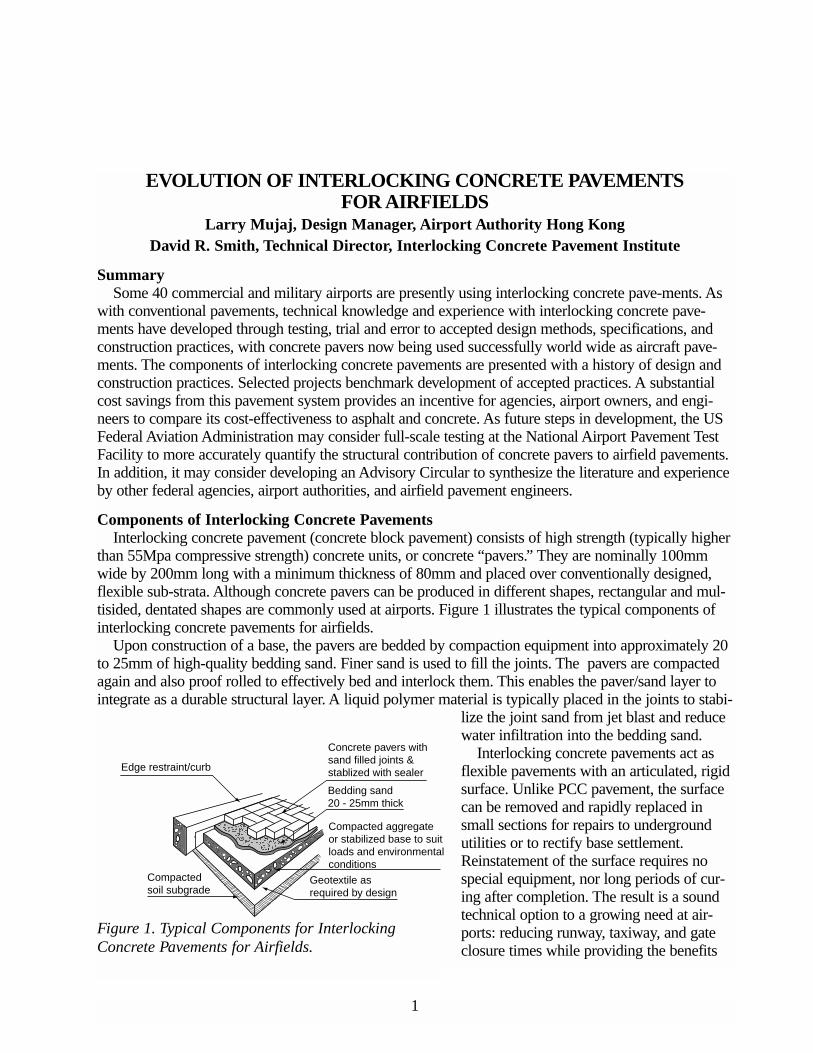
1 EVOLUTION OF INTERLOCKING CONCRETE PAVEMENTS FOR AIRFIELDS Larry Mujaj, Design Manager, Airport Authority Hong Kong David R. Smith, Technical Director, Interlocking Concrete Pavement Institute Summary Some 40 commercial and military airports are presently using interlocking concrete pave-ments. As with conventional pavements, technical knowledge and experience with interlocking concrete pave- ments have developed through testing, trial and error to accepted design methods, specifications, and construction practices, with concrete pavers now being used successfully world wide as aircraft pave- ments. The components of interlocking concrete pavements are presented with a history of design and construction practices. Selected projects benchmark development of accepted practices. A substantial cost savings from this pavement system provides an incentive for agencies, airport owners, and engi- neers to compare its cost-effectiveness to asphalt and concrete. As future steps in development, the US Federal Aviation Administration may consider full-scale testing at the National Airport Pavement Test Facility to more accurately quantify the structural contribution of concrete pavers to airfield pavements. In addition, it may consider developing an Advisory Circular to synthesize the literature and experience by other federal agencies, airport authorities, and airfield pavement engineers. Components of Interlocking Concrete Pavements Interlocking concrete pavement (concrete block pavement) consists of high strength (typically higher than 55Mpa compressive strength) concrete units, or concrete “pavers.” They are nominally 100mm wide by 200mm long with a minimum thickness of 80mm and placed over conventionally designed, flexible sub-strata. Although concrete pavers can be produced in different shapes, rectangular and mul- tisided, dentated shapes are commonly used at airports. Figure 1 illustrates the typical components of interlocking concrete pavements for airfields. Upon construction of a base, the pavers are bedded by compaction equipment into approximately 20 to 25mm of high-quality bedding sand. Finer sand is used to fill the joints. The pavers are compacted again and also proof rolled to effectively bed and interlock them. This enables the paver/sand layer to integrate as a durable structural layer. A liquid polymer material is typically placed in the joints to stabi- lize the joint sand from jet blast and reduce water infiltration into the bedding sand. Interlocking concrete pavements act as flexible pavements with an articulated, rigid surface. Unlike PCC pavement, the surface can be removed and rapidly replaced in small sections for repairs to underground utilities or to rectify base settlement. Reinstatement of the surface requires no special equipment, nor long periods of cur- ing after completion. The result is a sound technical option to a growing need at air- ports: reducing runway, taxiway, and gate closure times while providing the benefits Edge restraint/curb Concrete pavers with sand filled joints & stablized with sealer Bedding sand 20 - 25mm thick Compacted aggregate or stabilized base to suit loads and environmental conditions Compacted soil subgrade Geotextile as required by design Figure 1. Typical Components for Interlocking Concrete Pavements for Airfields.
Transcript of EVOLUTION OF INTERLOCKING CONCRETE PAVEMENTS FOR AIRFIELDS · EVOLUTION OF INTERLOCKING CONCRETE...
1
EVOLUTION OF INTERLOCKING CONCRETE PAVEMENTS FOR AIRFIELDS
Larry Mujaj, Design Manager, Airport Authority Hong KongDavid R. Smith, Technical Director, Interlocking Concrete Pavement Institute
SummarySome 40 commercial and military airports are presently using interlocking concrete pave-ments. As
with conventional pavements, technical knowledge and experience with interlocking concrete pave-ments have developed through testing, trial and error to accepted design methods, specifications, andconstruction practices, with concrete pavers now being used successfully world wide as aircraft pave-ments. The components of interlocking concrete pavements are presented with a history of design andconstruction practices. Selected projects benchmark development of accepted practices. A substantialcost savings from this pavement system provides an incentive for agencies, airport owners, and engi-neers to compare its cost-effectiveness to asphalt and concrete. As future steps in development, the USFederal Aviation Administration may consider full-scale testing at the National Airport Pavement TestFacility to more accurately quantify the structural contribution of concrete pavers to airfield pavements.In addition, it may consider developing an Advisory Circular to synthesize the literature and experienceby other federal agencies, airport authorities, and airfield pavement engineers.
Components of Interlocking Concrete PavementsInterlocking concrete pavement (concrete block pavement) consists of high strength (typically higher
than 55Mpa compressive strength) concrete units, or concrete “pavers.” They are nominally 100mmwide by 200mm long with a minimum thickness of 80mm and placed over conventionally designed,flexible sub-strata. Although concrete pavers can be produced in different shapes, rectangular and mul-tisided, dentated shapes are commonly used at airports. Figure 1 illustrates the typical components ofinterlocking concrete pavements for airfields.
Upon construction of a base, the pavers are bedded by compaction equipment into approximately 20to 25mm of high-quality bedding sand. Finer sand is used to fill the joints. The pavers are compactedagain and also proof rolled to effectively bed and interlock them. This enables the paver/sand layer tointegrate as a durable structural layer. A liquid polymer material is typically placed in the joints to stabi-
lize the joint sand from jet blast and reducewater infiltration into the bedding sand.
Interlocking concrete pavements act asflexible pavements with an articulated, rigidsurface. Unlike PCC pavement, the surfacecan be removed and rapidly replaced insmall sections for repairs to undergroundutilities or to rectify base settlement.Reinstatement of the surface requires nospecial equipment, nor long periods of cur-ing after completion. The result is a soundtechnical option to a growing need at air-ports: reducing runway, taxiway, and gateclosure times while providing the benefits
Edge restraint/curb
Concrete pavers with sand filled joints & stablized with sealer
Bedding sand 20 - 25mm thick
Compacted aggregate or stabilized base to suit loads and environmental conditions
Compacted soil subgrade
Geotextile as required by design
Figure 1. Typical Components for InterlockingConcrete Pavements for Airfields
Figure 1. Typical Components for InterlockingConcrete Pavements for Airfields.
2
of a concrete surface. They provide a surface with very good skid-resistant properties, high resistance todegradation from fuel and oil spills, resistance to damage from sudden dimensional changes thermally-induced by de-icing chemicals or from occasional jet blast, and to most concentrated loads from rampequipment.
Use of Concrete Pavers in Airfields Over 1 million m2 are in service world-wide at approximately 40 commercial, and military airports
with over 400,000m2 at the new Hong Kong airport. Other major projects include (1):• USA/Carribean – 24,000m2 of taxiways at Dallas/Fort Worth (B727, B737, MD-80) and
10,000m2 on Grand Cayman Island (B727, B737, MD-80).
• UK – Heavy aircraft (B747, B767) apron projects between 30,000m2 and 40,000m2 atHeathrow, Gatwick, Glasgow, Stanstead, Southhampton, Luton and aprons at 10 other militaryairfields.
• Europe – Aircraft aprons (B737, B757) at Trondheim, Kristiansand, and Stavanger, Norway;tug and equipment stands at Amsterdam Schiphol (5,000m2 to 26,000m2).
• Middle East – Aprons (B747) at Ben Gurion, Israel (13,000m2) and Fujairah, UAE (30,000m2)
• Australia – B747 aprons at Cairns (30,000m2) and a runway at Thevenard (26,000m2).
• Africa – B747 aprons at Jomo Kenyatta, Kenya, (56,000m2).
• Asia – Aprons (B747, A340) at Hong Kong Airport (400,000m2) and Subang, Malaysia(68,000m2)
In total, over 40 commercial and military airports have used interlocking concrete pavement for air-fields.
Experience has refined design methods and guide specifications for interlocking concrete pavement.As a result, they have been accepted by agencies responsible for airfield design and construction. Theseinclude the US Army Corps of Engineers and the US Air Force (3), the US Federal AviationAdministration (FAA) (2), Australian, British (1), Canadian (4), and Hong Kong airport authorities, theBritish Ministry of Defense (5), and NATO. The FAA has accepted recommendations on design andspecifications in a manual published by the Interlocking Concrete Pavement Institute (ICPI) and willpay for the use of interlocking concrete pavements with Airport Improvement Program (AIP) funds ona case-by-case basis (2). The 1995 ICPI manual includes an (unofficial) FAA-format specification, ItemP-502, Interlocking Concrete Paver Block Construction for Airport Pavement. It is hoped that FAA willissue an Advisory Circular with a guide specification
Cost ImplicationsInterlocking concrete pavements can be constructed at a cost less than rigid PCC pavements. This
has significant ramifications to airport operators and to FAA construction grant programs. The FAA hashistorically spent US$500 to $600 million per year on AIP funds (construction grants to airports) forconstruction and rehabilitation of apron and taxiway pavements. Approximately the same amount ofmoney has been contributed from other sources such as local airport authorities.
For new construction, interlocking concrete pavements can be 10% to 20% less expensive than PCCpavements. For rehabilitation of asphalt with an inlay or overlay of concrete pavers, a savings as highas 40% can occur when compared to removing the asphalt and replacing it with full-depth PCC pave-ment. (Savings would likely be less when comparing the cost of pavers overlaid on asphalt to anunbonded PCC overlay.) Applying these savings to construction and rehabilitation of aprons funded bythe FAA AIP program could yield annual saving of approximately $30 million. When applied to the

3
entire US commercial/cargo airport system, annual savingsappear to range between $60 to $300 million, depending on theextent of apron and taxiway construction or rehabilitation.
History Luton International Airport, England - The first appli-
cation of interlocking concrete pavement in an airfield occurredin 1981 at Luton International Airport (6). Two 20m2 test areaswith 80mm thick concrete pavers on bedding sand were con-structed to support landing gear for Boeing 737 aircraft. Theyreplaced worn, 100mm thick asphalt that was overlaid on250mm of PCC. Concrete pavers were found to be stable underwheel loads. From 1982 to 1984 a second trial area was con-structed as well as nine 300m2 areas within aircraft parkingbays. All of these are known to have performed satisfactorily.
From November 1988 to February 1989, a new, elevatedturning circle was constructed with approximately 5,500m2 of80mm thick concrete pavers placed on a thin layer of 6mmaggregate rather than bedding sand. This area was subjected torepeated full power, take-off thrust from jet engines, which dis-lodged 100m2 to 200m2 of concrete pavers in five separateincidents. (No stabilization material was placed in the joints tohold the sand in place.) Dislodged units in one incident dam-aged the surface of a B737 aircraft. The pavers were immedi-ately removed from both turning circles. Luton airport, howev-er, continued using concrete pavers in areas not subject to full-
power jet thrust, specifically at gate parking positions, and placed 6,000m2 at a new air cargo facility inJune 1993.
The primary lesson learned from the Luton airport experience is that concrete pavers should only beused in areas not subject to full jet thrust such as low-speed areas and parking positions. These includeareas subject to power-back or reverse thrust applied by departing aircraft at gates. The Luton experi-ence also demonstrated the following, which are now considered standard practice:• A joint stabilization sealer should be applied to the joints to prevent erosion of the sand from
between the pavers. This is typically a urethane pre-polymer material.
• Joint widths need to be between 2 and 4mm.
• The paver pattern should be fully interlocking.
• The design must include drainage of the bedding sand layer at the edges and a lowest eleva-tions in wide areas.
• The bedding sand should be concrete sand (2.3mm to 150mm in size) rather than 6mm sizedaggregate. This will prevent loss of the finer joint sand into the bedding material.
• Regular inspection of the pavement (as with all airfield pavement) is important to preventingproblems.
Cairns International Airport, Queensland, Australia –The first use of concrete pavers inAustralia was in 1990 where pavers were used to repair deformed pavement with marginal base materi-al on two aircraft parking positions at the domestic terminal (7). The repaired area consisted of pave-
Figure 2. Nine parking positionswere rehabilitated with interlockingconcrete pavement at LutonInternational Airport in 1983.
4
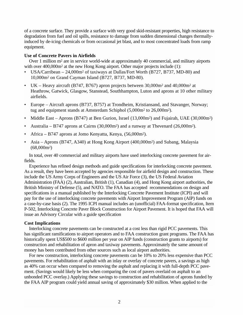
ment under the main and nose landing gear, plus the tug track.The initial trial encountered inconsistent joint spacing, ingressof water into the cement-treated base, and movement of thepavers. While the interlocking concrete pavement performedsatisfactorily in dry weather, the torrential, tropical rains soft-ened the base and subgrade and deformation followed fromwheel loads. This led to spalling and cracking of the paversand thus a potential FOD problem.
The construction of a new international terminal in 1991represented a fresh opportunity to address the problemsencountered with the paving at the domestic terminal. Some15,000m2 of concrete pavers covered three parking positionsfor B747-200/400, DC10-30, A300B4, and B767-200 at thenew terminal. See Figure 3.
The pavement design followed the US Army Corps ofEngineers CBR procedure using the flexible pavement designchart for the B747. The 15-year design life assumed for thepavement resulted in a cross section of 80mm thick concretepavers placed in a herringbone pattern, These were placed over20mm thick bedding sand and 250mm of cement-stabilizedbase over a sub-base. The top surface of the base was sealedwith 7mm chip seal to prevent loss of bedding sand into any
cracks in the cement-stabilized base. After six weeks of use, amajor 7,500L fuel spill occurred which had no effect on thepavement. Damage to the asphalt in the adjacent parking posi-
tion necessitated closing it for over 1 month until the asphalt again hardened. The project pointed to several requirements that appear in the most recent literature on design and
specifications. First, the quality of the concrete pavers must be tied to high testing standards and criteriafor compressive and/or tensile strength. They should be dimensionally consistent so that joint widthsremain consistent and tight. In practical terms, the concrete pavers should not vary 1.5mm in size com-pared to their specified dimensions.
Second, the texture of the pavers should be consistent for the sake of achieving consistent skid resist-ance properties. This is achieved by accepting samples and using a mock-up panel placed on the jobsite. The surface of pavers can be manufactured to be smooth or rough depending on the mix design ofthe concrete. While the texture depth of the surface can be measured, visual comparisons to a panel arefaster and easier.
Third, spacer bars or nibs on the vertical faces of the concrete pavers are essential. These nibs aretypically no larger than 2mm thick. They keep the pavers from touching each other (except at the nibs)which helps prevent chipping and spalling the top edges. This decreases the likelihood of FOD. Inaddition, spacers enable open joints so they can be filled with sand and receive (liquid) stabilizationmaterials such as urethane.
Fourth, joint spacing must be consistent in order to maximize a stable surface and facilitate interlockamong the pavers. The recommended range for joint spacing is 2 to 4mm with 3mm being the average.Spacer bars, combined with dimensionally consistent pavers and trained installers, will enable consis-tent joint widths. Spacers are desirable for manually installed pavement such as done at Cairns, andthey are considered essential on mechanically installed project such as those installed at Cayman andHong Kong airports.
Fifth, the bedding sand layer should be 20 to 25mm thick. While slightly thicker (25-40mm) bedding
Figure 3. 15,000 m2 apron was con-structed at Cairns Airport inQueensland, Australia in 1991.

5
is adequate for roadways, 20 to 25mm of sand reduces instability under significantly greater wheelloads. A thinner layer can be achieved on airfields since base surface tolerances tend to be tighter thanthose for roads.
Finally, proof rolling the surface of the pavers is considered important to accelerating the develop-ment of interlock. After the pavers are placed on the bedding sand, they are compacted with a platecompactor, the joints filled with sand and compacted again. A plate compactor with a minimum forceof 22kN is considered adequate to seat the pavers. However, after this compaction, the entire surfaceshould be proof rolled with a high-pressure, pneumatic-tired roller of at least 10t. This contributes tostability of the surface, helps identify areas of deficient joint sand, and loose or broken candidates forreplacement.
As a result of the Cairns project, a new industry specification was developed in Australia for airfieldsthat addressed these issues. Much of what was learned at Cairns was later applied at Hong Kong air-port, and to subsequent extensions of the Cairns apron.
Dallas/Fort Worth (DFW), Texas International Airport – As part of a 10-year plan to expandairport capacity, DFW plans the construction of two major runways and several new taxiways.Construction of cross-taxiways 23, 27, and 29 adjacent to the existing 18R/36L runway required nightclosure during the fall of 1991 (8)(9). Runway closure during construction had significant impact on airtraffic, causing significant delays in both air and ground operations. These delays not only impactedDFW, they rippled through much of America’s air traffic since DFW is a major hub connected todozens of other large, commercial airports.
The standard pavement cross-section at DFW is 430mm of jointed, reinforced concrete on 225mmof cement-treated base over 225mm to 460 mm of lime-stabilized subgrade. Use of this cross sectionrequired closures that were unacceptable to the airport and airlines. Interlocking concrete pavementswere selected because they could reduce nightly closures from 14 to 12 hours over a 114-night con-struction period. See Figure 4.
According a study for DFW by the regional office of the Air Transport Association (ATA), this savedan estimated $37,130 per day in delays to the airlines, or $4,232,820 over the 114-night construction. Inaddition, concrete pavers had anunexpected safety benefit. Whenthe cloud ceiling dropped below325m, airport operationsrequired that all constructioncease and the closed 18R/36Lrunway be opened for traffic.Unexpected stoppage of con-struction required removal of allworkers, material and equipmentwithin 30 minutes after notifica-tion from airport operations.This time constraint was metwith interlocking concrete pave-ment. In contrast, constructionof PCC pavement for high speedexits next to the same runwayinvolved two hours to clearequipment and personnel.
The basis of structural designwas the flexible method for flex-
Figure 4. The first use of concrete pavers was at Dallas/FortWorth, Texas International Airport, which saved over $4 millionin construction-related delays.

6
ible pavement in the FAA Advisory Circular 150/5320-6 “Airport Pavement Design and Evaluation”(10). The FAA concurred with replacing 100mm thick asphalt normally used in their flexible pavementdesign method with 80mm thick pavers and 40mm of bedding sand in the structural design method.
Wheel loads assumed for 20-year-life design ranged from 182 kN to 2,680 kN with 15% of the air-craft over 1,334kN. Actual loads measured from traffic monitoring were converted to an estimatedequivalent of MD-11 annual departures. An MD-11 has a gross load of 2,680kN and a wheel load inthe range of 225kN. From 1991 to 1994 the equivalent MD-11 loads were 7,029 for Taxiway 23, 832for Taxiway 27, and 938 for Taxiway 29 (10).
In 1990, prior to opening of the pavement, DFW staff measured elevations over a 3m grid. Skidresistance measurements taken with Saab skid tester ranged between 0.63 and 0.69 with 0.65 as anaverage. Structural capacity was measured using a falling weight deflectometer (FWD) to establishbase line data for future evaluations.
Harding Lawson Associates of Reno, Nevada, a consulting engineering firm, conducted an evalua-tion of the taxiways in 1995. The evaluation included measurement of elevations, a pavement distresssurvey covering 50% of taxiway 27, and 25% of 23 and 29, plus structural analysis using a FWD (9).
The most common surface distresses were loss of bedding sand along the edges of the pavementadjacent to concrete shoulders and to a lesser extent at the joints along the PCC pavement. Loss of sandat the shoulders was from heaving of the clay soils under the shoulders, since they were not stabilizedwith lime-flyash. In the taxiway interiors, loss of bedding sand and depressed pavers mirrored pavinglane joints in the CTB. No rutting, creep or swell was observed on the taxiways. In some areas of thetaxiways, the joints had lost sand to a depth of 20mm to 30mm from jet blast.
Deflection measurements were taken in 1994 with a Dynatest FWD. Table 1 below presents theaverage values for the measurements taken in 1991 and 1994.
Overall average deflection of the CTB increased 15%, 17% and 23% in the three taxiways.However, the stiffness of the paver and bedding sand layer increased 69%, 75% and 88%. This demon-strates the progressive stiffening or “lock-up” of interlocking concrete pavements under wheel loads.Total deflection decreased indicating that the entire pavement system stiffened from 1991 to 1994.
All of the modulii of the pavers and bedding sand in 1994 exceed 1,724MPa. This value is the stiff-ness recommended by the FAA for a 100mm thick asphalt layer when using layered elastic modelingand design. The data provides substantiation for the FAA assuming a structural equivalency of asphaltto the paver/sand layer.
The evaluation by Harding Lawson projected that the 20-year design life will be fulfilled with theexisting pavement structure. This was based on measured stiffness of the pavement materials, projectedaircraft traffic, analysis of fatigue of the CTB, analysis of allowable subgrade vertical compressivestrain, and allowable rut depth within the paver and bedding sand layer. The report concludes “concrete
1991 199423 0.60 0.4727 0.56 0.4729 0.70 0.60
Concrete Pavers1991 1994986 1,855
1,331 2,2481,014 1,772
Lime-stabilized subgrade1991 1994241 234186 172234 151
CTB1991 1994
17,241 14,36615,862 13,09017,241 9,683
Source: Reference 9
Taxiway Stiffness, MPaTaxiway Deflection, mm
Table 1Average Effective FWD Deflection and Stiffness of the Pavement Layers
7
pavers can provide a functional pavement surface for aircraft at DFW.” The FAA provided US$930,000in AIP funds to DFW to support the $1.8 million project. DFW airport represents the first use of inter-locking concrete pavements in an airport application in the USA.
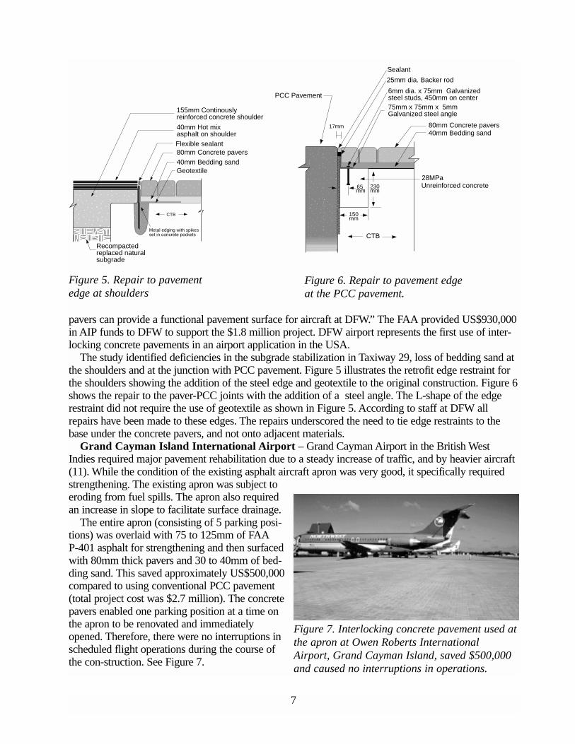
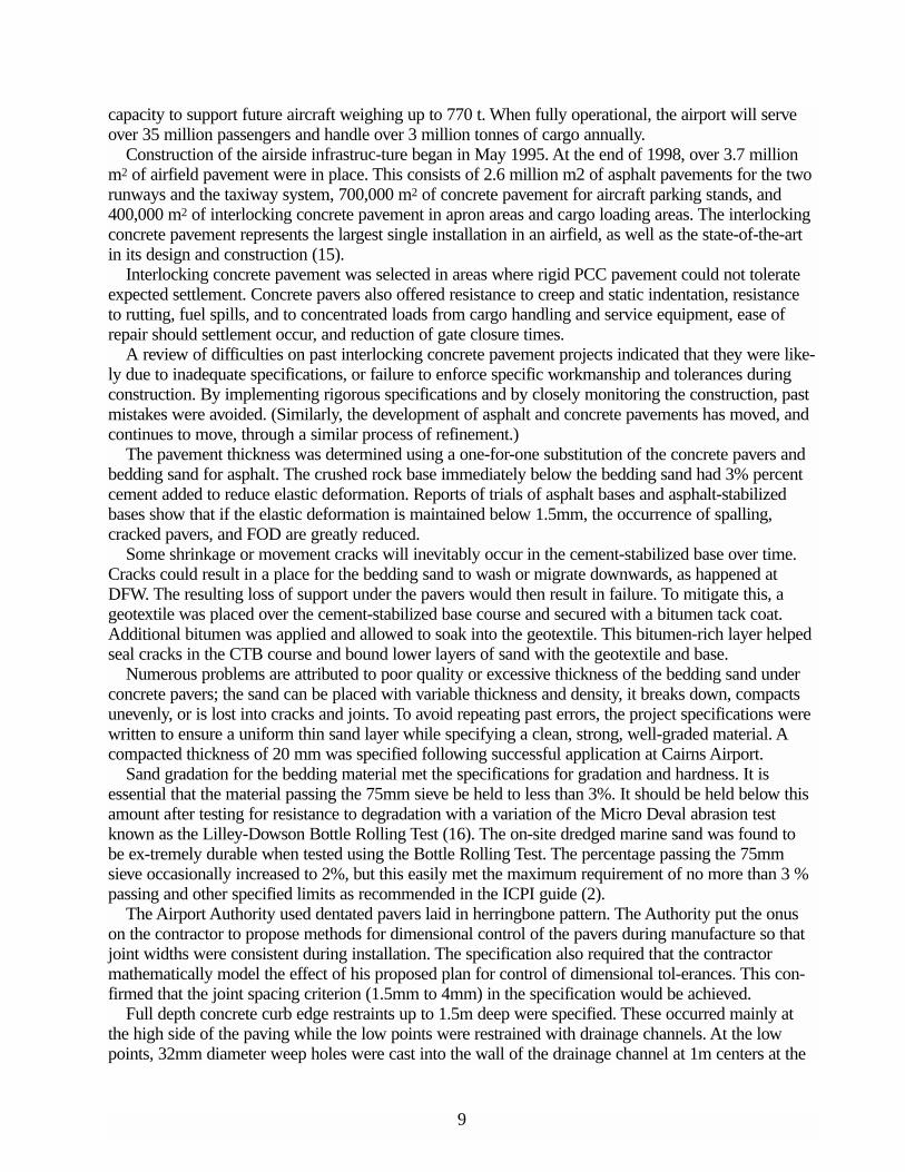
The study identified deficiencies in the subgrade stabilization in Taxiway 29, loss of bedding sand atthe shoulders and at the junction with PCC pavement. Figure 5 illustrates the retrofit edge restraint forthe shoulders showing the addition of the steel edge and geotextile to the original construction. Figure 6shows the repair to the paver-PCC joints with the addition of a steel angle. The L-shape of the edgerestraint did not require the use of geotextile as shown in Figure 5. According to staff at DFW allrepairs have been made to these edges. The repairs underscored the need to tie edge restraints to thebase under the concrete pavers, and not onto adjacent materials.
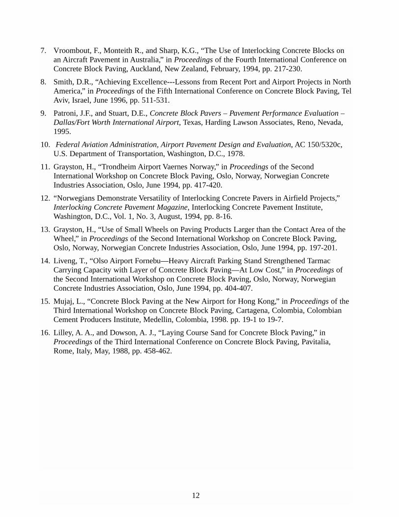
Grand Cayman Island International Airport – Grand Cayman Airport in the British WestIndies required major pavement rehabilitation due to a steady increase of traffic, and by heavier aircraft(11). While the condition of the existing asphalt aircraft apron was very good, it specifically requiredstrengthening. The existing apron was subject toeroding from fuel spills. The apron also requiredan increase in slope to facilitate surface drainage.
The entire apron (consisting of 5 parking posi-tions) was overlaid with 75 to 125mm of FAA P-401 asphalt for strengthening and then surfacedwith 80mm thick pavers and 30 to 40mm of bed-ding sand. This saved approximately US$500,000compared to using conventional PCC pavement(total project cost was $2.7 million). The concretepavers enabled one parking position at a time onthe apron to be renovated and immediatelyopened. Therefore, there were no interruptions inscheduled flight operations during the course ofthe con-struction. See Figure 7.
Sealant
25mm dia. Backer rod
6mm dia. x 75mm Galvanizedsteel studs, 450mm on center75mm x 75mm x 5mmGalvanized steel angle
40mm Bedding sand80mm Concrete pavers
28MPaUnreinforced concrete
PCC Pavement
CTB
150mm
230mm
17mm
65mm
155mm Continouslyreinforced concrete shoulder
40mm Hot mixasphalt on shoulderFlexible sealant80mm Concrete pavers40mm Bedding sandGeotextile
Metal edging with spikesset in concrete pockets
CTB
Recompactedreplaced naturalsubgrade
Figure 5. Repair to pavement edge at shoulders.
Figure 6. Repair to pavement edge at the PCC pavement.
Figure 5. Repair to pavementedge at shoulders
Figure 6. Repair to pavement edgeat the PCC pavement.
Figure 7. Interlocking concrete pavement used atthe apron at Owen Roberts InternationalAirport, Grand Cayman Island, saved $500,000and caused no interruptions in operations.

8
Overall, the pavement has performedwell. Like DFW, an inferior joint sand sta-bilization material was the substitute for aurethane-based material. This explains theloss of 20 to 30mm of joint sand in areassubject to jet blast similar to DFW (thesehave been refilled). A few of the paversunder the aircraft main gear have cracked inone or two parking positions. Small depres-sions have appeared in the pavement underthe main gear. This is likely due to marginallocal bedding sand. The cracked units havebeen replaced, and brought to their formerelevations.
The owner accepted occasional minorrepairs of pavers less costly than importing
extremely hard bedding sand at initial construction.The edge details to restrain the pavers and bedding sand were developed specifically for contact
against asphalt. Figure 8 shows this construction detail. A key to the success of this detail is paving theasphalt 60cm past the location of the steel edge. The compacted asphalt is saw cut back to the locationof the steel edge restraint. Cutting and removing the excess asphalt ensures the highest compactedmaterial adjacent to the concrete pavers and steel edge restraint.
Norwegian Airports – The experience at several Norwegian airports positively answers the ques-tion on the success of concrete pavers in winter climates, de-icing chemicals, and snow
plows. Snow plows and de-icing chemicals have been used regularly with little or no damage to thepavers at Trondheim, Kristiansand, Stavanger, Sola NATO base, and Oslo International Airport (all air-ports are located above 58o north latitude). All projects used urethane to stabilize the joint sand. Thismaterial has performed well with no maintenance.
Trondheim constructed 27,000m2 next to a new terminal in 1994. A high quality aggregate base sup-ports approximately 50 movements per day at seven gates from B737, B767, DC-8, and A320 traffic.The base and soil subgrade fills have experienced some differential settlement, which underscores theneed to use stabilized bases when aircraft loads exceed 45,500 kN. The concrete pavers have enduredunder steel snowplow blades (11)(12).
Kristiansand airport rehabilitated existing asphalt with a 6,650m2 inlay of concrete pavers in 1991.The pavement sees 15 to 20 B737s per day. Steel snowplow blades and glycol are used on the pave-ment to remove snow and ice (12) with no adverse results.
Braathens Airlines, Norway’s domestic air carrier has 7,500m2 at the entrance to their HeavyMaintenance Hangar for servicing some 20 B737s at Stavanger airport (12). Next to Stavanger airportis the Sola NATO base. Since 1989, it has maintained an annual rehabilitation program of replacingworn PCC taxiway pavement with concrete pavers for F-16s, C-130s, and rescue helicopters (13).
In 1991, Oslo Fornebu International Airport rehabilitated 8 asphalt stands (1,248m2) for B737s withan inlay of concrete pavers under the landing gear. This was an inexpensive, fast solution to staticindentation in the asphalt. All work was done at night, 3 nights per stand. In addition, the paver areashelp the pilots know where to park. A similar inlay of concrete pavers was done for parking of NATOmilitary aircraft elsewhere at Oslo airport (14).
Hong Kong – Airfield pavements at Hong Kong’s new international airport consist of two runwaysand associated taxiways leading to parking aprons for passenger aircraft, cargo, maintenance areas, andbusiness aviation. Pavements are designed for use by current aircraft and have sufficient structural
Figure 8 Edge restraint detail for overlay/inlayFigure 8. Edge restraint detail for overlay/inlay.
9
capacity to support future aircraft weighing up to 770 t. When fully operational, the airport will serveover 35 million passengers and handle over 3 million tonnes of cargo annually.
Construction of the airside infrastruc-ture began in May 1995. At the end of 1998, over 3.7 millionm2 of airfield pavement were in place. This consists of 2.6 million m2 of asphalt pavements for the tworunways and the taxiway system, 700,000 m2 of concrete pavement for aircraft parking stands, and400,000 m2 of interlocking concrete pavement in apron areas and cargo loading areas. The interlockingconcrete pavement represents the largest single installation in an airfield, as well as the state-of-the-artin its design and construction (15).
Interlocking concrete pavement was selected in areas where rigid PCC pavement could not tolerateexpected settlement. Concrete pavers also offered resistance to creep and static indentation, resistanceto rutting, fuel spills, and to concentrated loads from cargo handling and service equipment, ease ofrepair should settlement occur, and reduction of gate closure times.
A review of difficulties on past interlocking concrete pavement projects indicated that they were like-ly due to inadequate specifications, or failure to enforce specific workmanship and tolerances duringconstruction. By implementing rigorous specifications and by closely monitoring the construction, pastmistakes were avoided. (Similarly, the development of asphalt and concrete pavements has moved, andcontinues to move, through a similar process of refinement.)
The pavement thickness was determined using a one-for-one substitution of the concrete pavers andbedding sand for asphalt. The crushed rock base immediately below the bedding sand had 3% percentcement added to reduce elastic deformation. Reports of trials of asphalt bases and asphalt-stabilizedbases show that if the elastic deformation is maintained below 1.5mm, the occurrence of spalling,cracked pavers, and FOD are greatly reduced.
Some shrinkage or movement cracks will inevitably occur in the cement-stabilized base over time.Cracks could result in a place for the bedding sand to wash or migrate downwards, as happened atDFW. The resulting loss of support under the pavers would then result in failure. To mitigate this, ageotextile was placed over the cement-stabilized base course and secured with a bitumen tack coat.Additional bitumen was applied and allowed to soak into the geotextile. This bitumen-rich layer helpedseal cracks in the CTB course and bound lower layers of sand with the geotextile and base.
Numerous problems are attributed to poor quality or excessive thickness of the bedding sand underconcrete pavers; the sand can be placed with variable thickness and density, it breaks down, compactsunevenly, or is lost into cracks and joints. To avoid repeating past errors, the project specifications werewritten to ensure a uniform thin sand layer while specifying a clean, strong, well-graded material. Acompacted thickness of 20 mm was specified following successful application at Cairns Airport.
Sand gradation for the bedding material met the specifications for gradation and hardness. It isessential that the material passing the 75mm sieve be held to less than 3%. It should be held below thisamount after testing for resistance to degradation with a variation of the Micro Deval abrasion testknown as the Lilley-Dowson Bottle Rolling Test (16). The on-site dredged marine sand was found tobe ex-tremely durable when tested using the Bottle Rolling Test. The percentage passing the 75mmsieve occasionally increased to 2%, but this easily met the maximum requirement of no more than 3 %passing and other specified limits as recommended in the ICPI guide (2).
The Airport Authority used dentated pavers laid in herringbone pattern. The Authority put the onuson the contractor to propose methods for dimensional control of the pavers during manufacture so thatjoint widths were consistent during installation. The specification also required that the contractormathematically model the effect of his proposed plan for control of dimensional tol-erances. This con-firmed that the joint spacing criterion (1.5mm to 4mm) in the specification would be achieved.
Full depth concrete curb edge restraints up to 1.5m deep were specified. These occurred mainly atthe high side of the paving while the low points were restrained with drainage channels. At the lowpoints, 32mm diameter weep holes were cast into the wall of the drainage channel at 1m centers at the

10
level of the bedding sand to aid in the drainage of the bedding sand. This is considered good practice todissipate excess water and reduce the chance of pore pressure build-up in the bedding sand (15). Toensure that the bedding sand was not washed away through the weep holes, the geotextile con-tinuedup the face of the drainage channel to 10mm below the surface.
With over 400,000 m2 to be laid at an average of 1,000 m2 per day, it was necessary to use mechani-cal installation equipment. See Figures 9 and 10. To maintain a continuous herringbone pattern, thepavers were hand-stacked in layers on pallets in the factory in the required herringbone pattern. (Wherelabor costs are higher in other parts of the world, hand stacking is uneconomical. Rather, each layer ismanufactured in a ready-to-install herringbone pattern.) Two stack-bonded pavers were placed in diago-nally opposite corners to help in the locating and laying of the cluster. When the cluster was laid, thecorner pavers were removed and the clusters were locked together as shown in Figure 11.
Mechanical installation was done using three laying machines. Following training of site personneland some further development of the machines, laying rates of 500 m2 per day were easily achievedwith each. The pavers where seated into the bedding sand using a 350kg plate compactor on a rubberpad that transmitted a compactive force of 0.08 MPa. This is a similar force to traditional, smaller 22kNforce plate compactors. The larger plate area enabled faster and more consistent compaction.
Paver installation usually began against at a concrete curb. Special hand-laid edge pavers and manu-factured half units were used to start the herringbone pattern. Cut pavers were applied at the closing
Figure 9. 400,000 m2 of concretepavers at Hon Kong Airport repre-sents the largest airport applicaitonin the world.
Figure 10. The size of the pavement neces-sitated the use of mechanical installationthat placed as much as 500 m2 permachine per day.
Figure 11. Machine-made clusters of concrete pavers are joined on site to make a fully interlock-ing surface.

11
edges, around pits and manholes, and at changes in direction of the pattern. Diamond saw cuttingensured a clean, smooth face, as well as uniform joints and contact areas. All cut pavers were largerthan 25% of the whole unit. Cut faces were always chamfered to replicate whole pavers. Randomchecks of a 1m2 area for every 250m of pavement were made to confirm the specified joint spacing.
One problem occurred when the joint sand stabilization material was applied. Pavements leftunsealed for long periods in dusty areas developed a layer of silt in the joints. This effectively preventedthe sealer from soaking into the joints resulting in a skin on the surface which had to be removed byhigh-pressure water spraying.
A low-viscosity elastomeric pre-polymer stabilized the sand in the joints. Penetration of the sealerinto the joints averaged between 20mm and 30mm. Higher penetration was avoided because if itoccurred near the bedding sand weep hole, the geotextile over the weep holes would clog and becomeineffective. While there is little performance history, the joint sand stabilizer is expected to last at least10 years.
With the opening of the new Hong Kong Airport on July 6, 1998, the interlocking concrete pave-ment came into service under frequent heavy aircraft loads. At the time of writing this paper, no load-related failures were evident.
ConclusionAs with asphalt and concrete, specifications for interlocking concrete pavements for airfields will be
subject to continual refinement. However, after 15 years of experience, the critical aspects of design,specifications, and construction with concrete pavers have been addressed. The projects represented inthis paper highlight the learning process engineers have gone through to develop industry-acceptedstandards. This increases the confidence by airport pavement engineers and operators in the use ofinterlocking concrete pavements. Further confidence and more precise structural design methods couldbe gained by the testing at the FAA National Airport Pavement Test Facility. An FAA AdvisoryCircular (AC) on interlocking concrete pavements would also confirm this cost-effective pavement bysynthesizing the literature and experience from other federal agencies, airport authorities, and airfieldpavement engineers. It would support AIP projects, thereby facilitating realization of construction costsavings and/or reduced interruptions to airport operations.
References1. Knapton, J. and Emery J., The Use of Pavers for Aircraft Pavements, CAA Paper 96001, Civil
Aviation Authority, London, England, March 1996.
2. McQueen, R. D, Knapton, J., Emery, J, and Smith, D. R., Airfield Pavement Design withConcrete Pavers (US Edition), Interlocking Concrete Pavement Institute, Washington, D.C.,1995.
3. Anderton, G. L., Concrete Block Pavement for Airfields, Technical Report GL-91-12,Waterways Experiment Station, Corps of Engineers, Department of the Army, Vicksburg,Mississippi, July 1991.
4. Hein, D., Airfield Pavement Design with Concrete Pavers (Canadian Edition), InterlockingConcrete Pavement Institute, Washington, D.C., 1995.
5. Concrete Block Paving for Airfields, Defence Works Functional Standard Specification 035,Ministry of Defence, West Midlands, England, March 1996.
6. Emery, J. A., “Concrete Pavers for Aircraft Pavement Surfaces,” Journal of TransportationEngineering, Vol. 112, No. 6, November, 1986, Paper No. 21041, American Society of CivilEngineers, Reston, Virginia, pp. 609-623.
12
7. Vroombout, F., Monteith R., and Sharp, K.G., “The Use of Interlocking Concrete Blocks onan Aircraft Pavement in Australia,” in Proceedings of the Fourth International Conference onConcrete Block Paving, Auckland, New Zealand, February, 1994, pp. 217-230.
8. Smith, D.R., “Achieving Excellence---Lessons from Recent Port and Airport Projects in NorthAmerica,” in Proceedings of the Fifth International Conference on Concrete Block Paving, TelAviv, Israel, June 1996, pp. 511-531.
9. Patroni, J.F., and Stuart, D.E., Concrete Block Pavers – Pavement Performance Evaluation –Dallas/Fort Worth International Airport, Texas, Harding Lawson Associates, Reno, Nevada,1995.
10. Federal Aviation Administration, Airport Pavement Design and Evaluation, AC 150/5320c,U.S. Department of Transportation, Washington, D.C., 1978.
11. Grayston, H., “Trondheim Airport Vaernes Norway,” in Proceedings of the SecondInternational Workshop on Concrete Block Paving, Oslo, Norway, Norwegian ConcreteIndustries Association, Oslo, June 1994, pp. 417-420.
12. “Norwegians Demonstrate Versatility of Interlocking Concrete Pavers in Airfield Projects,”Interlocking Concrete Pavement Magazine, Interlocking Concrete Pavement Institute,Washington, D.C., Vol. 1, No. 3, August, 1994, pp. 8-16.
13. Grayston, H., “Use of Small Wheels on Paving Products Larger than the Contact Area of theWheel,” in Proceedings of the Second International Workshop on Concrete Block Paving,Oslo, Norway, Norwegian Concrete Industries Association, Oslo, June 1994, pp. 197-201.
14. Liveng, T., “Olso Airport Fornebu—Heavy Aircraft Parking Stand Strengthened TarmacCarrying Capacity with Layer of Concrete Block Paving—At Low Cost,” in Proceedings ofthe Second International Workshop on Concrete Block Paving, Oslo, Norway, NorwegianConcrete Industries Association, Oslo, June 1994, pp. 404-407.
15. Mujaj, L., “Concrete Block Paving at the New Airport for Hong Kong,” in Proceedings of theThird International Workshop on Concrete Block Paving, Cartagena, Colombia, ColombianCement Producers Institute, Medellin, Colombia, 1998. pp. 19-1 to 19-7.
16. Lilley, A. A., and Dowson, A. J., “Laying Course Sand for Concrete Block Paving,” inProceedings of the Third International Conference on Concrete Block Paving, Pavitalia,Rome, Italy, May, 1988, pp. 458-462.