Evolution of Digital conception
32
Evolution of Digital conception
description
Evolution of Digital conception. Summary. How it was in the Past ? Conception : The UART case VHDL and reusability Future methods for making digital circuits Conclusion. In the PAST. Few years ago digital circuits were: With few functionalities =>Not very complex - PowerPoint PPT Presentation
Transcript of Evolution of Digital conception

Evolution of Digital conception
Summary How it was in the Past ?
Conception : The UART case
VHDL and reusability
Future methods for making digital circuits
Conclusion

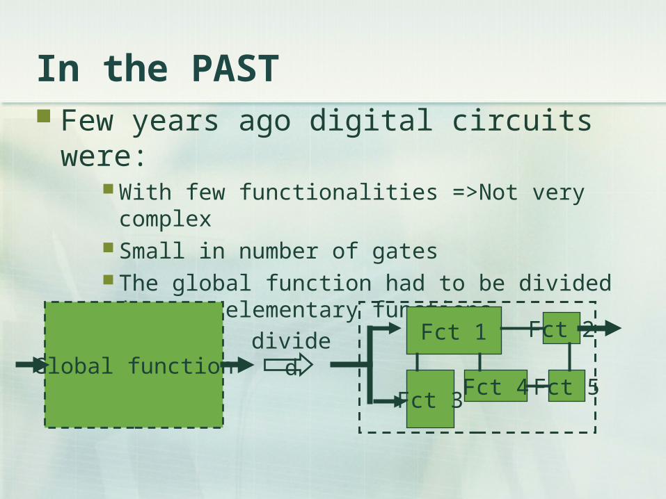
In the PAST Few years ago digital circuits were:
With few functionalities =>Not very complex Small in number of gates The global function had to be divided in very
elementary functions.
Global function
Fct 1
Fct 5Fct 4Fct 3
Fct 2divided
In the PAST Few years ago digital circuits were:
With few functionalities =>Not very complex Small in number of gates The global function had to be divided in very
elementary functions.
Global function
Fct 1
Fct 5Fct 4Fct 3
Fct 2divided
In the PAST
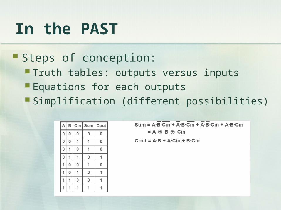
Steps of conception: Truth tables: outputs versus inputs Equations for each outputs Simplification (different possibilities)
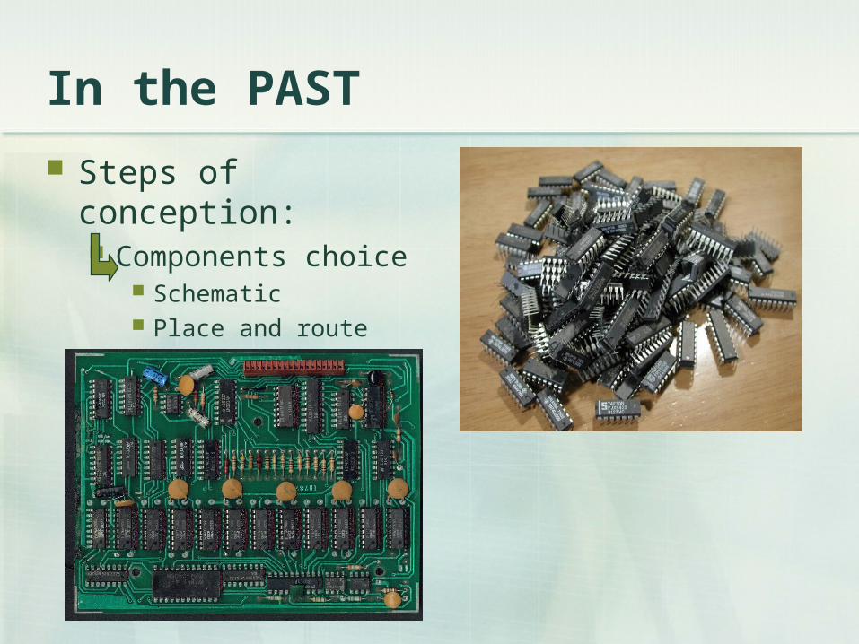
In the PAST
Steps of conception: Components choice
Schematic Place and route
In the PAST
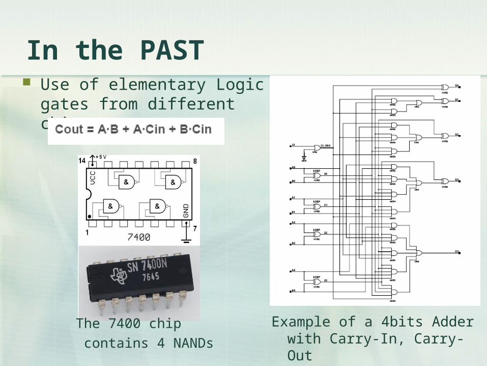
Example of a 4bits Adder with Carry-In, Carry-Out
The 7400 chip
contains 4 NANDs
Use of elementary Logic gates from different chips

In the PAST
Why this method can’t be used to create huge and complex digital circuits ?
Takes too much place on a board
Difficulty of reuse: Very elementary functions Totally dependant of the hardware choice (components) 1 modification => do everything again.
Implementation of the UART
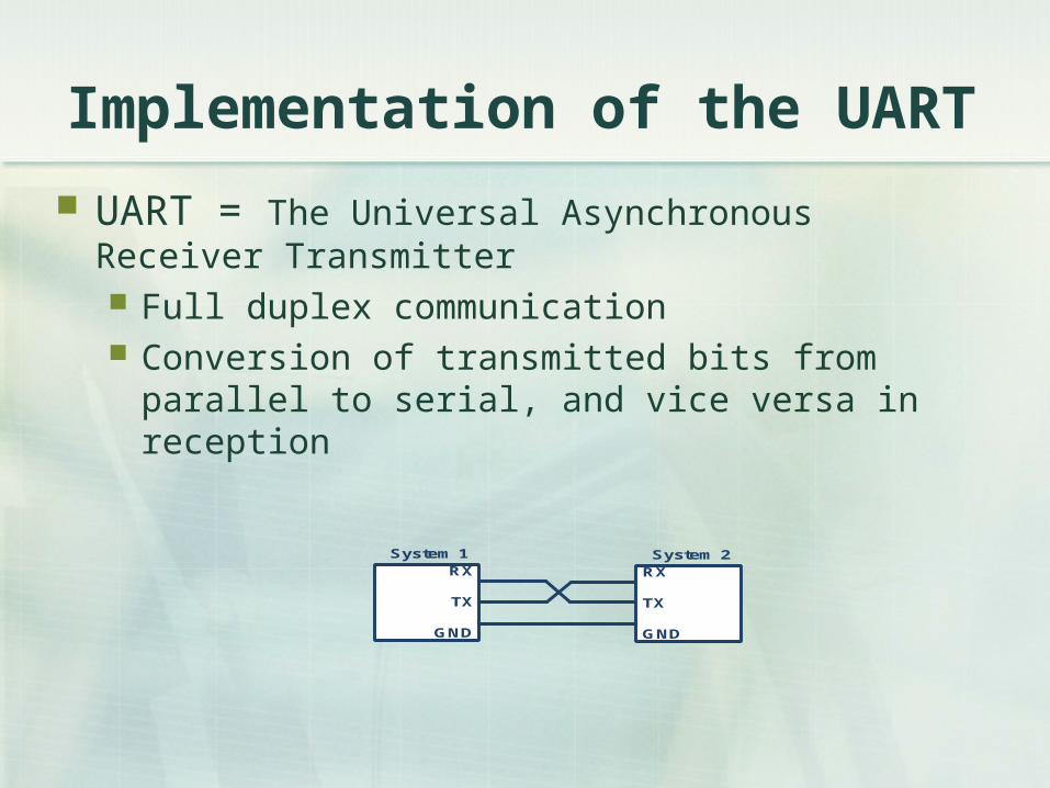
UART = The Universal Asynchronous Receiver Transmitter Full duplex communication Conversion of transmitted bits from parallel to serial,
and vice versa in reception
RX
TX
GND
System 1 System 2RX
TX
GND
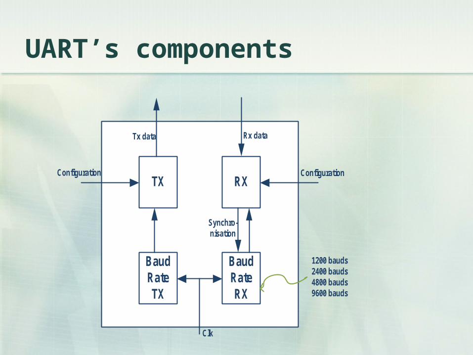
UART’s components
TX RX
Baud Rate TX
Baud Rate RX
Configuration Configuration
Tx data Rx data
Synchro-nisation
Clk
1200 bauds2400 bauds4800 bauds9600 bauds
Frame format
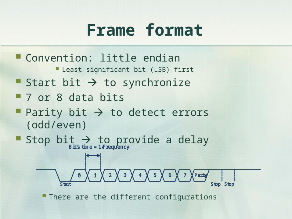
Convention: little endian Least significant bit (LSB) first
Start bit to synchronize 7 or 8 data bits Parity bit to detect errors (odd/even) Stop bit to provide a delay
There are the different configurations
Bit’s time = 1/Frequency
Start
0 1 2 3 4 5 6 7 Parity
Stop Stop
Synchronisation
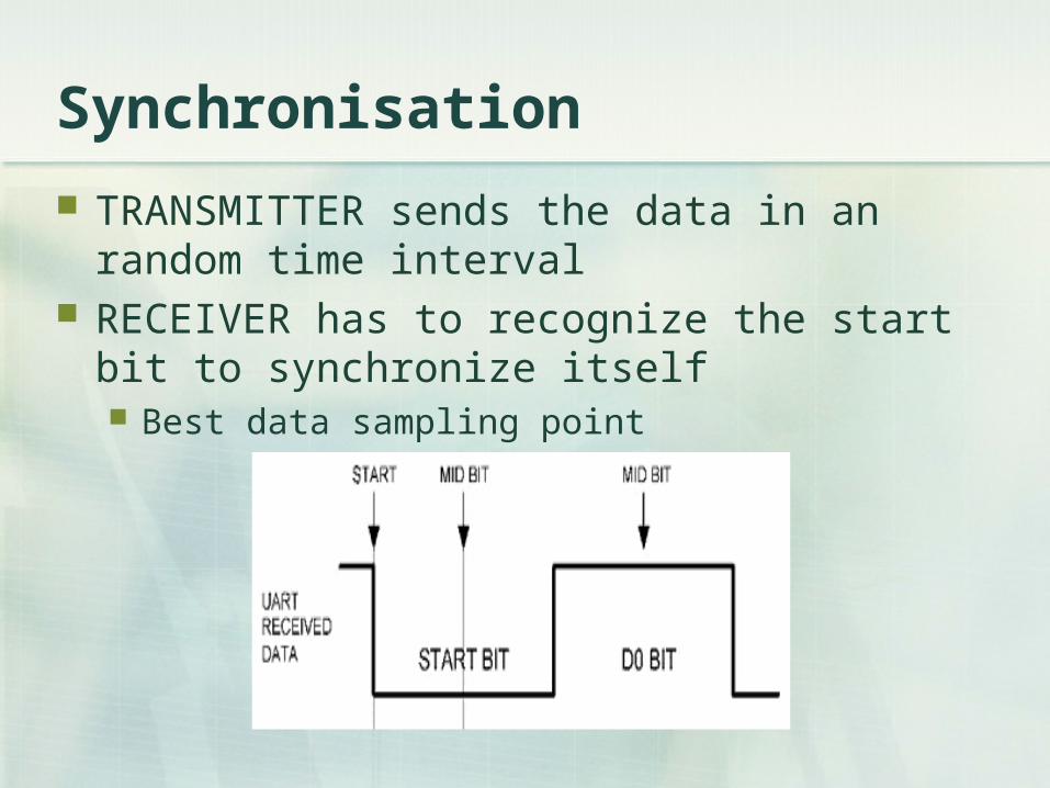
TRANSMITTER sends the data in an random time interval
RECEIVER has to recognize the start bit to synchronize itself Best data sampling point
Chronogram (transmitter)
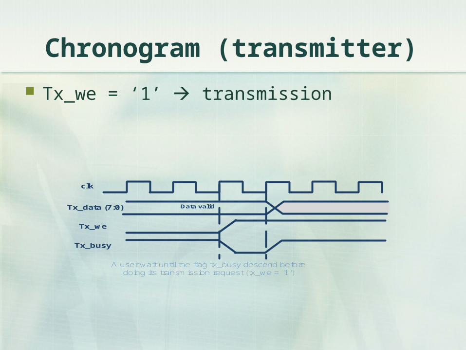
Tx_we = ‘1’ transmission
Data valid
clk
Tx_data (7:0)
Tx_we
Tx_busy
A user wait until the flag tx_busy descend before doing its transmission request (tx_we = ‘1’)
Chronograms (receiver)
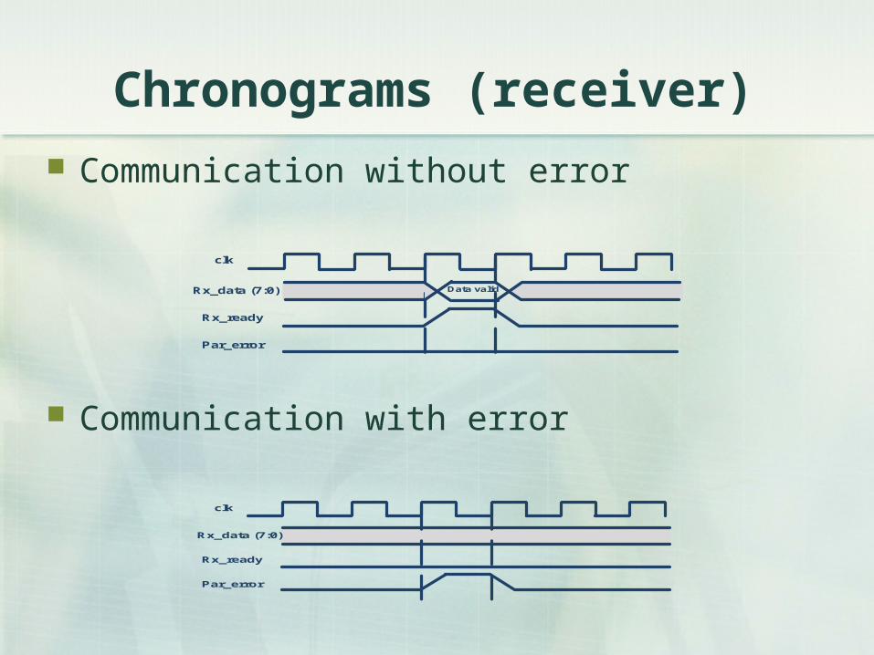
Communication without error
Data valid
clk
Rx_data (7:0)
Rx_ready
Par_error
clk
Rx_data (7:0)
Rx_ready
Par_error
Communication with error
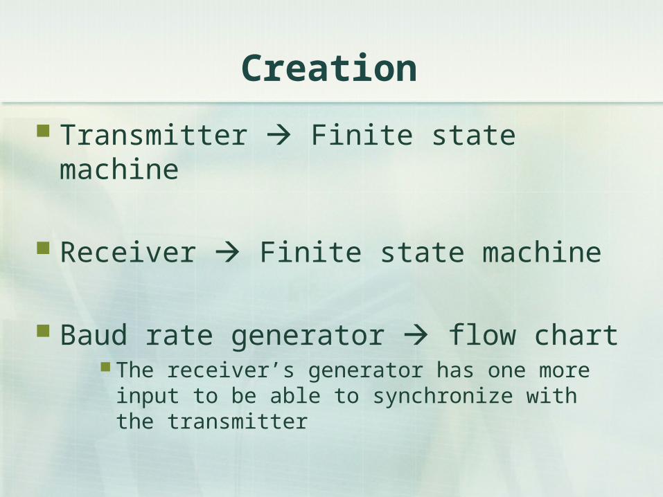
Creation
Transmitter Finite state machine
Receiver Finite state machine
Baud rate generator flow chart The receiver’s generator has one more input to be
able to synchronize with the transmitter
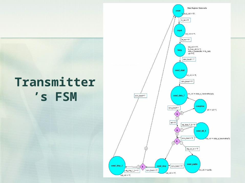
Transmitter’s FSM
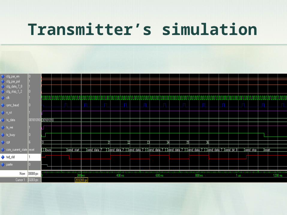
Transmitter’s simulation
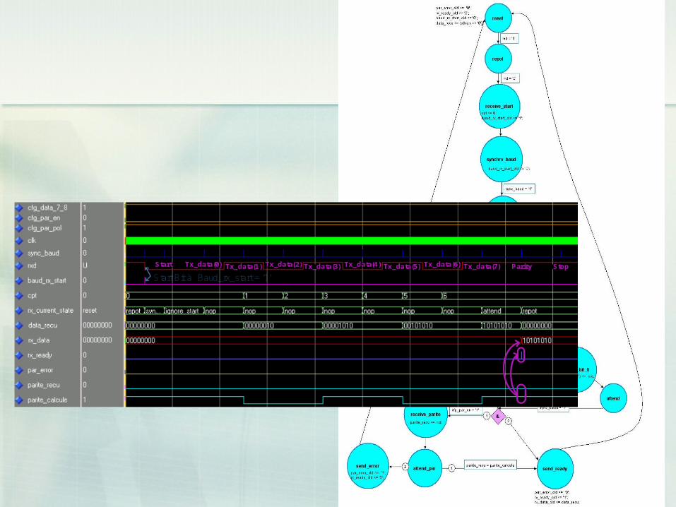
Receiver’s FSM
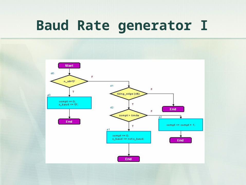
Baud Rate generator I
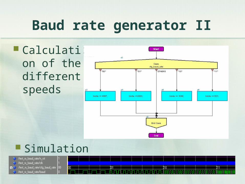
Baud rate generator II
Calculation of the different speeds
Simulation
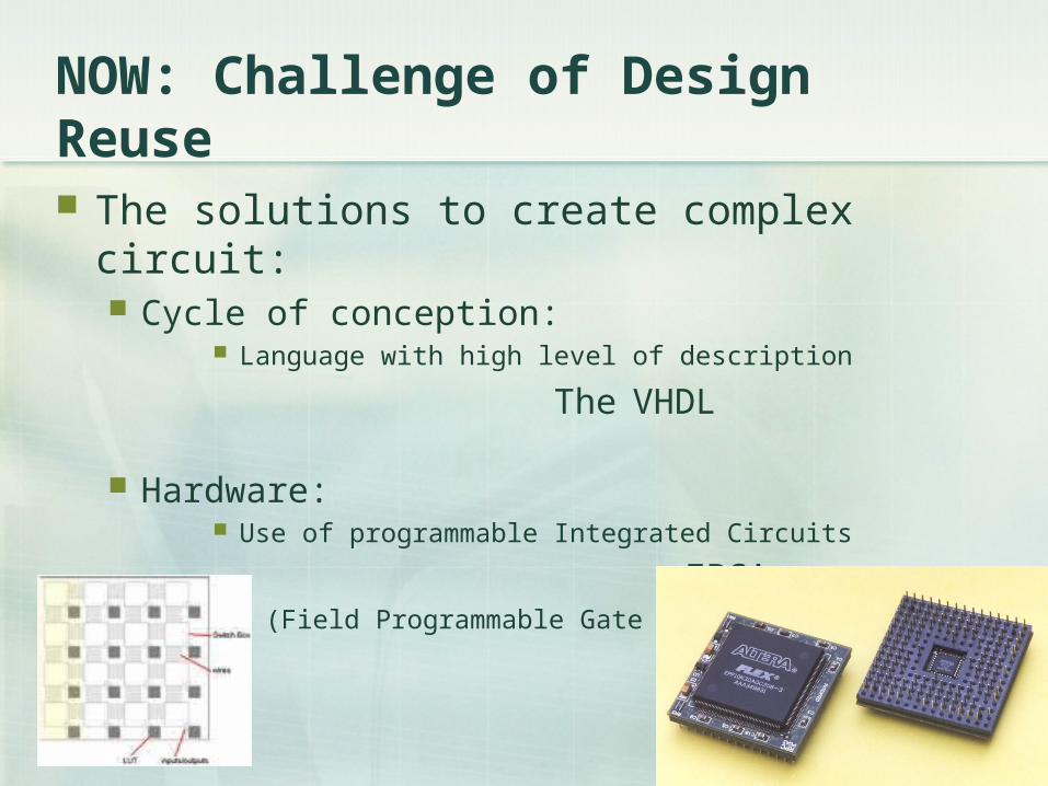
NOW: Challenge of Design Reuse
The solutions to create complex circuit: Cycle of conception:
Language with high level of description
The VHDL
Hardware: Use of programmable Integrated Circuits
FPGA
(Field Programmable Gate Array)
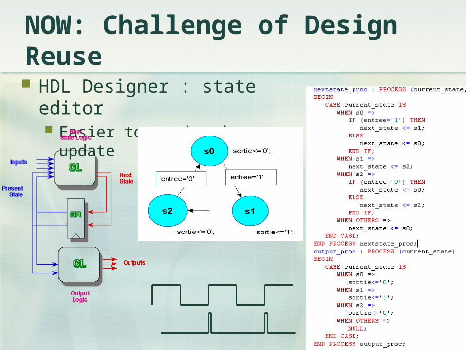
NOW: Challenge of Design Reuse
HDL Designer : state editor Easier to read and update
NOW: Challenge of Design Reuse
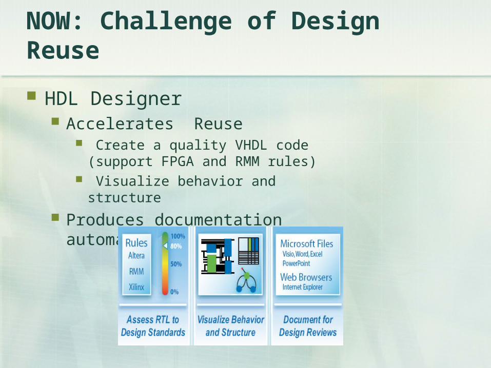
HDL Designer Accelerates Reuse
Create a quality VHDL code (support FPGA and RMM rules)
Visualize behavior and structure
Produces documentation automatically
Catapult C (1/2)
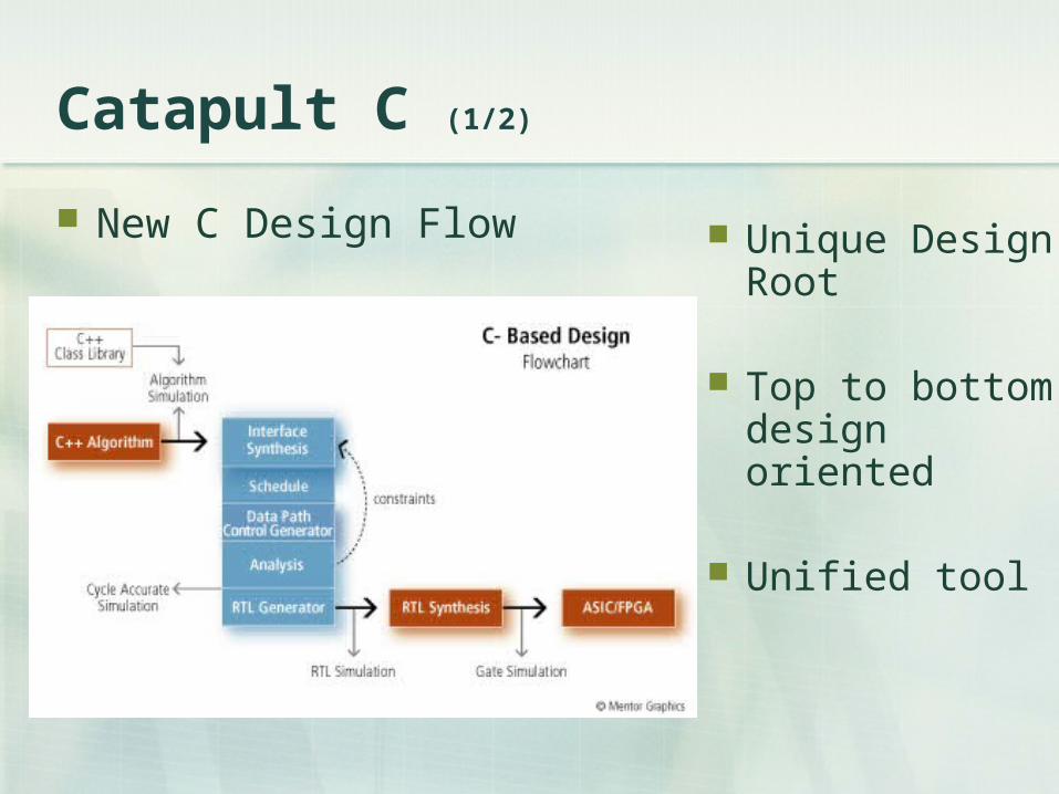
New C Design Flow Unique Design Root
Top to bottom design oriented
Unified tool
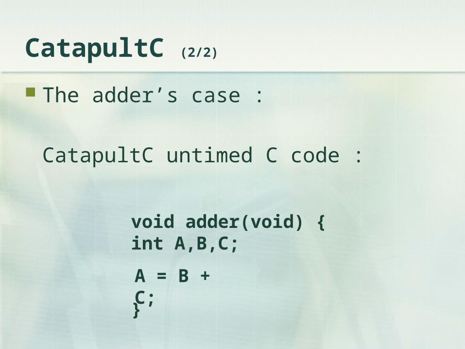
void adder(void) {int A,B,C;
}
CatapultC (2/2)
The adder’s case :
CatapultC untimed C code :
A = B + C;
Modifications made simple
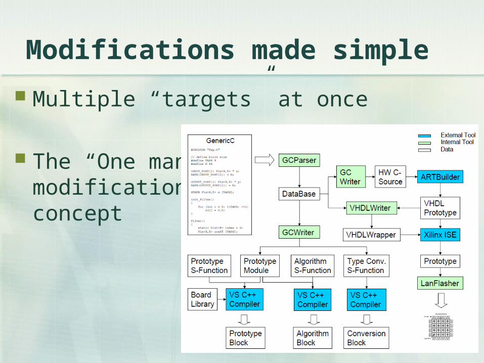
Multiple “targets” at once
The “One man” modification concept

Synthesis made simple 1/2
Example : a Finite Impulse Response Filter

Synthesis made simple 2/2
Outputs human readable VHDL code
3500 linesin 10 seconds
and …
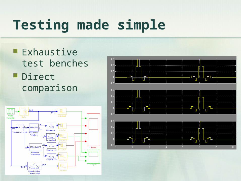
Testing made simple
Exhaustive test benches
Direct comparison

Catapult C and beyond
Increased Specification to Market rate
Bundled Tool
Helps to find the best solution
Conclusion (1/2)
VHDL, VHDL Designer and Catapult permit: To do more complex circuits To reduce de conception time
Conclusion (2/2)
Thanks for coming and listening !
Please feel free to ask any question.