Evolution of API RP2A-WSD
25
© 2012 Chevron U.S.A., Inc. All rights reserved. Design Requirements for Fixed Steel Structures in API and ISO Moises A. Abraham, Chevron December 2012 Platong II – Gulf of Thailand
-
Upload
geeawhiz55 -
Category
Documents
-
view
770 -
download
12
description
offshore structurescode development
Transcript of Evolution of API RP2A-WSD

© 2012 Chevron U.S.A., Inc. All rights reserved.
Design Requirements for Fixed Steel Structures in API and ISO
Moises A. Abraham, ChevronDecember 2012
Platong II – Gulf of Thailand

© 2012 Chevron U.S.A., Inc. All rights reserved.
Topics of Discussion
– Evolution of API RP 2A-WSD 21st Edition into the 22nd Edition.
– Changes in the 22nd Edition of RP2A-WSD.
– New Tubular Joint Strength Provisions in the 22nd Edition.
– Coexistence of API RP 2A-WSD 22nd Edition and API RP 2A-LRFD 2nd
Edition.
– Alignment of API Offshore Structures Standards with ISO 19900 Series.
– Adopting ISO 19902 for RP2A-LRFD 2nd Edition.
– Code Check Comparison between ISO 19902 and API RP 2A-WSD 21st
Edition.
– Review of Calibration Methodology in the 1980s.
– Topics of Discussion
– References
2

© 2012 Chevron U.S.A., Inc. All rights reserved.
Evolution of API RP 2A-WSD 21st Edition into the 22nd
Edition.
3
API RP 2A-WSD21st Edition
API RP 2GEN
API RP 2MET
API RP GEO
API RP 2A-WSD22nd Edition
API RP 2EQ
API RP 2SIM
API RP 2TOP
API RP 2MOP
Published
Will be published in 2013
Being Developed

© 2012 Chevron U.S.A., Inc. All rights reserved.
Changes in the 22nd Edition of RP 2A-WSD
– Balloted in 2011 and approved with 96% of the votes cast.
– 22nd Edition final table of contents to include 3 new sections i.e. Scope, Normative References and Terms, Definitions and Acronyms. Three sections were removed i.e. Section 14 – Surveys, Section 17 –Assessment of Existing Platforms and Section 18 – Fire, Blast and Accidental Loadings.
– The 1989 edition of AISC Specification for Structural Steel Buildings (ASD) is included as a normative reference. LRFD in later editions of this AISC specification are based on calibration with building design practices and may not be applicable to offshore platforms.
– Section 4.7 contains an updated guidance to determine “Exposure Category” used in selecting required level of design for platforms.
– Users are referred to API 2MET for wind, wave and current environmental data previously included in 2A. The detailed steps to follow in applying the data from API 2MET remain in 2A.
4

© 2012 Chevron U.S.A., Inc. All rights reserved.
Changes in the 22nd Edition of RP 2A-WSD
– The newly required robustness assessment for new platforms is a check for platform survival in a lower probability extreme event.
– The elevation of the underside of the deck for new L-1 and L-2 platforms must be no lower than the 1000-year return period max crest elevation provided in API 2MET.
– While the 22nd edition no longer recommends a minimum of 1.5m (5 ft) air gap, the user is reminded to allow for any known or predicted seafloor subsidence, water depth uncertainty, platform rotation, etc.
– Extreme Level Earthquake (ELE) and Abnormal Level Earthquake (ALE) are defined in 2EQ. The ELE was the Strength Level Earthquake (SLE) and the ALE was the Ductility Level Earthquake (DLE) in earlier editions of RP 2A.
– “Simplified Fatigue” was removed from the commentary to be consistent with API 2MET. Wave conditions for which the simplified approach was calibrated are no longer in 2MET. All new and reused structures are now required to have a detailed fatigue analysis.
5
© 2012 Chevron U.S.A., Inc. All rights reserved.
Changes in the 22nd Edition of RP 2A-WSD
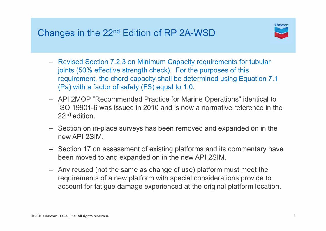
– Revised Section 7.2.3 on Minimum Capacity requirements for tubular joints (50% effective strength check). For the purposes of this requirement, the chord capacity shall be determined using Equation 7.1 (Pa) with a factor of safety (FS) equal to 1.0.
– API 2MOP “Recommended Practice for Marine Operations” identical to ISO 19901-6 was issued in 2010 and is now a normative reference in the 22nd edition.
– Section on in-place surveys has been removed and expanded on in the new API 2SIM.
– Section 17 on assessment of existing platforms and its commentary have been moved to and expanded on in the new API 2SIM.
– Any reused (not the same as change of use) platform must meet the requirements of a new platform with special considerations provide to account for fatigue damage experienced at the original platform location.
6

© 2012 Chevron U.S.A., Inc. All rights reserved.
– The new tubular joint strength equations are based on screened test databases, augmented by an extensive new series of validated nonlinear FE simulations.
– Additional experimental information available of the effect of additional chord loads on joint capacity was incorporated in the new formulation.
– The increased reliability (reduced scatter) provided by the new static strength formulation justified the reduction in load factor of safety to 1.6 from the previous value of 1.7.
– Joint classification is unchanged from the 21st edition.
– A new brace load interaction equation is adopted. This new interaction equation provides a better fit to the available test data than does the arc sine expression in the 21st edition.
New Tubular Joint Strength Provisions in API RP 2A-WSD 22nd Edition by Pecknold et al.
7
0.12
opbaipbaa MM
MM
PPIR

© 2012 Chevron U.S.A., Inc. All rights reserved.
New Tubular Joint Strength Provisions in API RP 2A-WSD 22nd Edition by Pecknold et al.
– The punching shear design formulation has been fully eliminated.
– The formulas for have been completely revised
– The format of the basic capacity equations remain unchanged from the 21st edition:
– The 0.8d multiplier in the 21st edition for has been eliminated and absorbed by the coefficient.
– The new and formulations more accurately reflect the influence of joint geometry in particularly chord diameter-to-thickness ratio () and chord loads on joint capacity and are a significant improvement over previous practice (21st
edition). The strength load factor depends only on joint geometry ( and ). is excluded because it has only a minor effect.
8
sin
sin2
2
FSdTF
QQM
FSTF
QQP
yfua
yfua
uQ fQ
uQ
fgu QQQQ ,,,
uQ aM

© 2012 Chevron U.S.A., Inc. All rights reserved.
Interaction Curve for Tubular Joints Under Combined Axial and Uni-directional Moment Loading
9
Pa =Qu Qf Fyc T2 /(FS sin)Ma =Qu Qf Fyc T2 d/(FS sin)
Joint Strength CheckIR = |P/Pa| + |M/Ma|ipb
2 + |M/Ma|opb
API WSD
API LRFD
ISO 19902Puj =Qu Qf Fy T2 /(sin)
Muj =Qu Qf Fy T2 d/(sin)
Joint Strength CheckUj=|PB/PD| + |MB/MD|ipb
2 + |MB/MD|opb
Puj =Qu Qf Fy T2 /(sin)Muj =Qu Qf Fy T2 (0.8d) / (sin)
Joint Strength CheckIR=1-cos[(/2)(PD/jPuj)] + [(MD/jMuj)ipb
2 + (MD/jMuj)opb2]0.5
0
0.1
0.2
0.3
0.4
0.5
0.6
0.7
0.8
0.9
1
0.0 0.2 0.4 0.6 0.8 1.0
P/P m
ax
M/Mmax
Interaction Curve for P + M
API LRFD (P+Mipb or Mopb)
ISO (P+Mipb)
ISO (P+Mopb)

© 2012 Chevron U.S.A., Inc. All rights reserved.
Coexistence of API RP 2A-WSD 22nd Edition and API RP 2A-LRFD 2nd Edition.
10
API RP 2A-WSD21st Edition
API RP 2GEN
API RP 2MET
API RP GEO
API RP 2A-WSD22nd Edition
API RP 2EQ
API RP 2SIM
API RP 2TOP (LRFD) ?
API RP 2MOP
API RP 2A-LRFD1st Edition
(Withdrawn)
API RP 2A-LRFD2nd Edition

© 2012 Chevron U.S.A., Inc. All rights reserved.
Alignment of API Offshore Structures Standards with ISO 19900 Series.
11
API RP 2GEN
API RP 2MET
API RP GEO
API RP 2A-WSD22nd Edition
API RP 2EQ
API RP 2SIM
API RP 2TOP LRFD
API RP 2MOP ?
API RP 2A-LRFD2nd Edition
ISO 19900
ISO 19901-1
ISO 19901-4
ISO 19902
ISO 19901-2
?
ISO 19901-3
ISO 19901-6

© 2012 Chevron U.S.A., Inc. All rights reserved.
Adopting ISO 19902 for RP2A-LRFD 2nd Edition
– API RP 2A – LRFD has been withdrawn and a modified version of ISO 19902 will be adopted for RP 2A-LRFD 2nd Edition.
– Task Group 19 composed of 22 members started the work in 2009.
– Activities completed:• Task group has completed the review of 25 sections of ISO 19902.
• Written comments on the DNV Report “Comparison of API, ISO, and NORSOK Offshore Structural Standards” were submitted by task group members.
• A code check comparison has been performed between API WSD and ISO 19902.
• API will fund analytical studies (platform UC check comparisons). The project will start in early 2013 and last for two years.
3 contractors perform 3 platform analyses.
Chevron will run one additional platform analysis.
12

© 2012 Chevron U.S.A., Inc. All rights reserved.
Code Check Comparison between ISO 19902 and API RP 2A-WSD 21st Edition
13
Jacket dead load = 2000 kipsDeck dead load = 3000 kips

© 2012 Chevron U.S.A., Inc. All rights reserved.
Code Check Comparison between ISO 19902 and API RP 2A-WSD 21st Edition
14
Pile Members Unity Check___ ISO 19902___ API 21st Edition
0.540.60
0.850.90
1.111.13

© 2012 Chevron U.S.A., Inc. All rights reserved.
Code Check Comparison between ISO 19902 and API RP 2A-WSD 21st Edition
15
Row 2 Members Unity Check___ ISO 19902___ API 21st Edition
0.930.760.55
0.59
0.350.34
0.660.73

© 2012 Chevron U.S.A., Inc. All rights reserved.
Code Check Comparison between ISO 19902 and API RP 2A-WSD 21st Edition
16
Joint Unity Check___ ISO 19902___ API 21st Edition
0.890.97
0.961.02
0.891.21
0.831.40
0.210.24
0.220.24
0.290.36

© 2012 Chevron U.S.A., Inc. All rights reserved.
– Pile UCs above the mudline are similar in API and ISO.
– When hydrostatics is included in the analysis, API and ISO yield different results due to treatment of capped-end forces. The table below shows maximum UCs for two water depths.
– Hydrostatic pressure will dominate deep water jackets and compliant towers in LRFD.
– ISO equation 14.3-13 controls the design of critical joints. The intent of the equation is to make critical joints stronger than braces, but the effect may be too severe.
– Different conical transition designs requirement between ISO and API.
Code Check Comparison between ISO 19902 and API RP 2A-WSD 21st Edition
17
HydrostaticHead (ft)
API UC ISO UC ISO Equation
276 0.92 0.76 13.2-31350 1.41 0.96 13.2-31
zj
b
opbd
B
ipbd
B
d
Bj
UMM
MM
PPU
2 Minimum Capacity
check in API
© 2012 Chevron U.S.A., Inc. All rights reserved.
Review of Calibration Methodology by Fred Moses et al. to Develop API RP 2A-LRFD in the 1980s
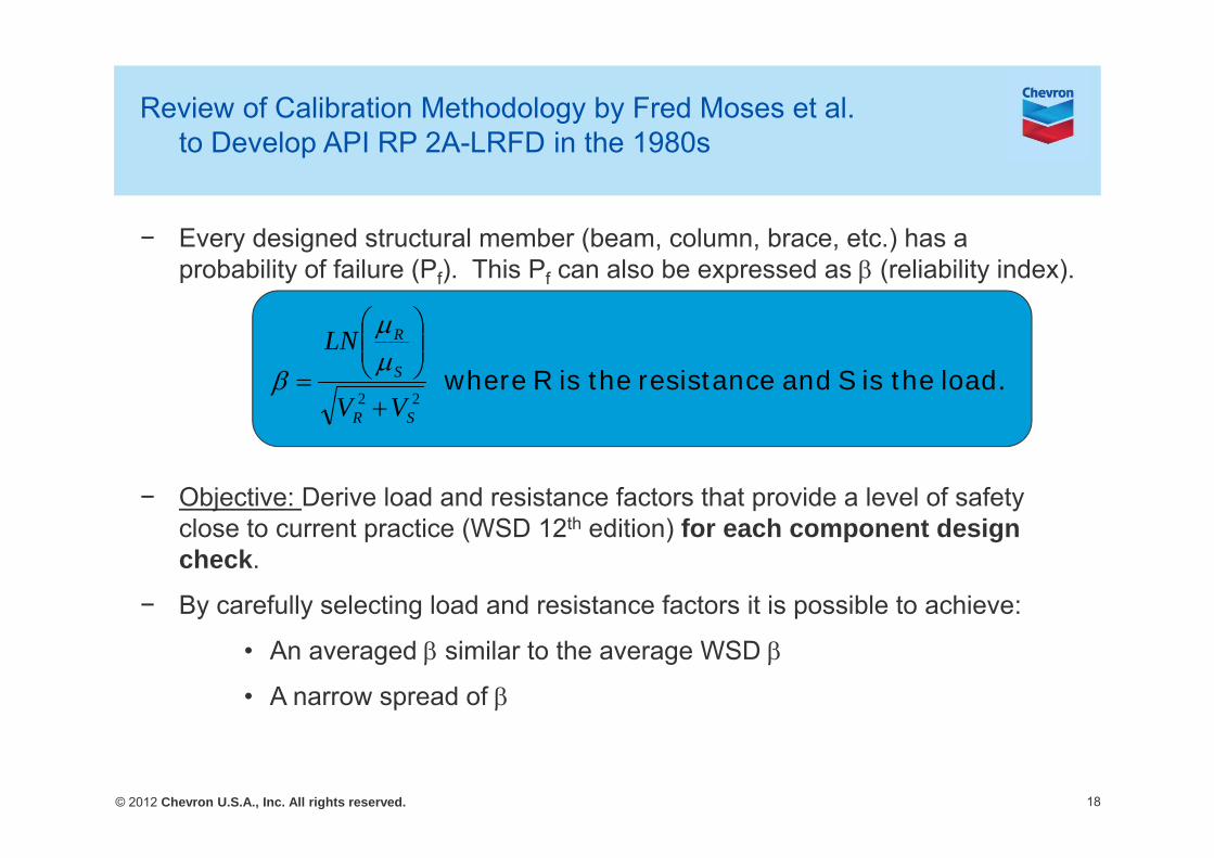
− Every designed structural member (beam, column, brace, etc.) has a probability of failure (Pf). This Pf can also be expressed as (reliability index).
− Objective: Derive load and resistance factors that provide a level of safety close to current practice (WSD 12th edition) for each component design check.
− By carefully selecting load and resistance factors it is possible to achieve:
• An averaged similar to the average WSD
• A narrow spread of
18
load. the is S and resistance the isR where 22
SR
S
R
VV
LN

© 2012 Chevron U.S.A., Inc. All rights reserved.
Review of Calibration Methodology by F. Moses toDevelop API RP 2A-LRFD in the 1980s
19
Source: OTC 5699
The average for each of the curves is similar, but the spread of the LRFD curve is smaller.
In the 1980s calibration, was between 2.01 and 2.78 for different components i.e. yield, bending, buckling, tubular joints, etc.

© 2012 Chevron U.S.A., Inc. All rights reserved.
Acceptable probabilities of Failure from F. Moses Work (1988)
20
)( fP Is Guassian probability distribution function
Range of API 2A-LRFD
Range of API 2A-WSD(12th edition, used in original calibration)
Pf of 3x10⁻⁵
Proposed for L1 structures (Permanently Manned)

© 2012 Chevron U.S.A., Inc. All rights reserved.
Target Probabilities of Failure in ISO 19902 and API – Regional Differences.
− Partial action factors in ISO 19902 were derived from F. Moses Work for the GOM. Hamonization in safety levels requires location-dependent partial action factors.
− A target probability of failure of 3x10⁻⁵ per year has been proposed for new, permanently manned, installations.
− Fatigue damage design factors are harmonized in ISO and API
21
Environment Partial Action Factor (f,E )
Mean RSR
Gulf of Mexico 1.58* 2.16*Australia 1.59 2.18
North Sea 1.40 1.82
1.25 and 1.35 DfEf ,,
Failure Critical Inspectable Not InspectableNo 2 5Yes 5 10

© 2012 Chevron U.S.A., Inc. All rights reserved.
Points of discussion
– Code check equations have evolved in recent years (i.e. tubular joint checks). Has this evolution changed the validity of the load and resistance factors developed by Moses et al in the 1980s? Do we need to recalibrate?
– Have the wind and wave probability distributions changed (mean and COV)? Should partial action factors be revised to achieve the same performance levels?
– Are code check comparisons between codes enough to validate and harmonize the standards?
– How do we reconcile the tubular joint check differences between ISO and API?
– Research work is now in progress to incorporate strength provisions of the new AISC specification into offshore design practices. How do we reconcile the deck design approach in API 2TOP and ISO 19901-3?
– Target reliabilities for offshore installations that are evacuated or unmanned during the design event (loss of life is negligible) have been developed by cost-benefit analysis (incremental cost of improving safety). These analyses performed in the 1980s guided updates to API. Do we need to revisit these analyses and reassess target reliabilities?
22

© 2012 Chevron U.S.A., Inc. All rights reserved.
References
− OTC 5699, 1988, “Calibration of the Draft RP2A-LRFD for Fixed Platforms”, F. Moses and R.D. Larrabee.
− OTC 5882, 1988, “Development of a Reliability-Based Alternative to API RP2A”, J.R. Lloyd, and D.I. Karsan.
− OTC 23443, 2012, “Alignment of API Offshore Structures Standards with ISO 19900 Series and Usage of the API suite”, D. Wisch, A. Mangiavacchi.
− OTC 17310, 2005, “New API Tubular Joint Strength Design Provisions”, D. Pecknold, P. Marshall and J. Bucknell.
− OTC 23558, 2012, “Insights into Using the 22nd Edition of API RP 2A Recommended Practice for Planning, Designing and Constructing Fixed Offshore Platforms – Working Stress Design”, K. A. Digre and F.J. Zwerneman.
− Load factor calibration for ISO 13819 Regional Annex: Component Resistance, Offshore Technology Report, MSL Engineering Limited, 2001.
− Implications for the Assessment of Existing Fixed Steel Structures of Proposed ISO 13819-2 Member Strength Formulations, PAFA Consulting Engineers, August 2000.
23

© 2012 Chevron U.S.A., Inc. All rights reserved.
Review of Calibration Methodology by Fred Moses et al. to Develop API RP 2A-LRFD in the 1980s
− For a Tension Yield Check, the random variables used in the original calibration by Fred Moses:− Dead Load (D): D = 1.0*nominal and VD = 8%
− Live Load (L): L = 1.0*nominal and VL = 14%
− Extreme Environmental Load(W): W = 0.7*nominal and VW = 37%
− Yield strength (R): R = 1.1*nominal and VR = 13%
− Where R=Ay with R>1.67(D+L) and R>1.25(D+L+W)
− Assuming nominal values DN=1, LN=3, WN=4
− The reliability index can be easily calculated as 2.3.
• Do we need to update the mean and V values?
• In 2MET W = 0.76*nominal and VW = 41%?
24

© 2012 Chevron U.S.A., Inc. All rights reserved.
Load and Resistance Factors – API LRFD & ISO 19902
– Load factors in ISO 19902 are identical to those in API LRFD 1st edition, except:
• 1.35 only applies to the GoM (L1 structures), other regions have to determine their own coefficient.
• 1.17 only applies to the GoM (L2 structures – 15% loading reduction from L1).
– ISO 19902 resistance factors are identical to those in API LRFD.
25


![OFFSHORE TECHNOLOGY REPORT 2001/082 - HSE · 2019. 12. 5. · 2.2 API RP2A The reference editions for RP2A in this study are WSD 20th Edition [1] and LRFD 1st Edition [2] both published](https://static.fdocuments.in/doc/165x107/60b655a8570b2271555916ab/offshore-technology-report-2001082-hse-2019-12-5-22-api-rp2a-the-reference.jpg)