Evita 4 · 2018-09-13 · What's new in Evita 4 software 4.n* Specification of the humidifier used...
192
Evita 4 Intensive Care Ventilator Instructions for Use Software 4.n 1-159-99 D M E D I C A L
Transcript of Evita 4 · 2018-09-13 · What's new in Evita 4 software 4.n* Specification of the humidifier used...
Evita 4Intensive Care VentilatorInstructions for UseSoftware 4.n
1-15
9-99
DM E D I C A L

2
Working with these Instructions for Use
Header line – the title...of the main chapterThe title of the specific sub-section is printed underneaththe main header – to help you find your way quickly fromsubject to subject.
Page body...the Instructions for Use in combined text/illustrations. The information isexpressed in the form of practical actions, giving the userdirect hands-on experience in learning how to use themachine.
Left-hand column – the text...provides explanations and instructs the user step-by-stepin the practical use of the product, with short, clearinstructions in easy-to-follow sequence.Bullet points indicate separate actions. Where severalactions are described, numbers are used both to refer tothe relevant details in the illustrations and to specify thesequence of actions.
Right-hand column – the illustrations...provide the visual reference for the text and make it easierto locate the various parts of the equipment. Elementsmentioned in the text are highlighted. Unnecessary detailsare avoided.Screen displays prompt the user to proceed and confirmcorrect actions.
Working with these Instructions for Use
Calibrating the CO2 sensor
The CO2 sensor must be calibrated:
– if the check values are not met on checkingcalibration with filter or calibration gas.
– as part of the half-yearly inspection of Evita 4.
● Switch on Evita 4. Wait about for 3 minutes for the machine to complete its warm-up phase.
● Press the »Calibration« key.
Display (example):
● Touch »CO2« screen key.
Display (example):
● Carry out CO2 zero calibration, page 74.
After the CO2 zero calibration:
Touch the »Cal.« screen key.
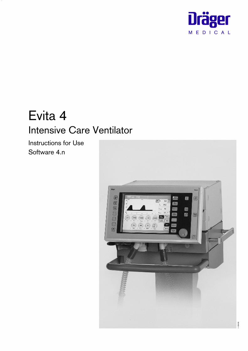
● Connect the calibration gas supply.Use the cuvette from the calibration set!
1 Connect the calibration gas cylinder and thecuvette of the calibration set to the hose.
2 Remove the CO2 sensor from its park bracket and fit it to the cuvette of the calibration set.
● Read the CO2, O2 and N2O concentrations(vol.%) of the calibration gas from the test cylinder.
OperationCalibrating
2
1
3

What's new in Evita 4 software 4.n*
Specification of the humidifier used– »Active humidifier«
or– »HME/Filter« (artificial nose)– for more accurate measurement of the volume
parameters
Apnoea ventilation On/Off– can be selected as starting configuration
Extended range of settings for the alarm time TApnoea >>>>– from 5 to 60 seconds
(formerly 15 to 60 seconds)
Frequency can be reduced to 0– for BIPAP and SIMV, for weaning without transitions
Ventilation mode BIPAPAssist
– for pressure-controlled assisted ventilation
Patient mode »prev. patient« can be selected– to adopt the settings, including alarms, which were
effective before switching off the equipment
Leakage compensation On/Off– for activation and deactivation of the automatic
leakage compensation function
Extended logbook entries– Evita 4.4n identifies alarms which are active but not
displayed with an asterisk
Monitoring of tube blockages– New alarm message »Tube blocked !!!«
Additional weaning parametersavailable as software version 4.n plus upgradein addition to the parameter occlusion pressure P 0.1Evita 4.4n also determines the parameters– RSB Rapid Shallow Breathing indexand – NIF Negative Inspiratory Force index
External flow source available as software version 4.n plus upgrade– The amount of external flow is calculated by Evita 4.4n
(e.g. for additional tracheal gas insufflation) andadjusts the volume monitoring tolerances in order toavoid inadvertent alarms
Extended use of loop presentationsavailable as software version 4.n plus upgrade– Loops can be zoomed and frozen– Loops can be displayed permanently in the upper part
of the screen
Evita Remote (Remote Pad) optionally available– Remote control pad for parallel remote operation of
function keys on Evita 4
NIV optionally available– Application mode to support non-invasive ventilation
therapies
Nurse call optionally available– Connection for transmitting alarm signals to a central
hospital alarm station
* See pages 187 and 188 for new features in software versions 2.n and 3.n
3
What's new in Evita 4 software 4.n

4

For Your Safety and that of Your Patients ..............................................11
Intended Medical Application.................................................................. 13
Operating Concept...................................................................................15
Structure of the Control Unit................................................................... 16
On-Screen Controls................................................................................. 17Screen Keys for Function Selection without Confirmation..................................................................................18Screen keys for Function Selection,Adjustment and Confirmation.....................................................................18On-Screen Parameter Setting Knobs.........................................................20
Screen Pages...........................................................................................21Standard page...........................................................................................22»Adjustment« Screen Page........................................................................ 22»Alarm Limits« Screen Page...................................................................... 24»Measured values« Screen Page............................................................... 25»Measurement Manoeuvre« Screen Page.................................................. 26»Calibration« Screen Page.........................................................................26»Configuration« Screen Page.....................................................................27
Positioning the Control Unit.....................................................................27Ergonomic Positioning...............................................................................27
Preparation...............................................................................................29
Attaching components.............................................................................30Fitting expiration valve................................................................................30Fitting flow sensor..................................................................................... 30Fitting O2 sensor capsule.......................................................................... 31
Note on Use of Heat and Moisture Exchanger (HME)............................. 31
Ventilation Adults and Children............................................................... 32Connecting Aquapor humidifier..................................................................32Connecting ventilation hoses..................................................................... 32Fitting temperature sensor......................................................................... 33Fitting CO2 cuvette and CO2 sensor......................................................... 34
Ventilating Infants.................................................................................... 34Fitting bacterial filter.................................................................................. 34Fitting humidifier and ventilation hose.........................................................35
5
Contents
Contents

If using bacterial filters............................................................................ 35
Supply and Connections..........................................................................36Electrical power supply..............................................................................36Note on use of a socket strip for ancillary equipment..................................36Temporary interruption of power supply..................................................... 36Gas supply................................................................................................37
Evita Remote (optional).............................................................................38Connection................................................................................................38Note automatic self-test............................................................................. 39
Nurse call (optional)..................................................................................40Technical Data...........................................................................................40
Before Using for the First Time............................................................... 41Selecting the language of the display texts.................................................41
Device Check........................................................................................... 42Before use on patient................................................................................ 42Performing device check........................................................................... 43Checking the hose system for leaks...........................................................46
Positioning the control unit......................................................................47To position the control unit on the wall rail..................................................47To position the control unit on the device................................................... 47
Operation................................................................................................. 49
Starting up............................................................................................... 50Switching on............................................................................................. 50
Patient mode............................................................................................50Selecting the patient mode........................................................................ 51Entering the ideal body weight................................................................... 51Select the previous settings.......................................................................51Starting ventilation..................................................................................... 52
Setting Ventilation Modes........................................................................53IPPV..........................................................................................................53SIMV, SIMV/ASB......................................................................................57BIPAP, BIPAP/ASB.................................................................................. 60BIPAPAssist................................................................................................62CPAP, CPAP/ASB....................................................................................63MMV, MMV/ASB...................................................................................... 65APRV........................................................................................................ 67
Independent Lung Ventilation ILV............................................................ 69Preparation................................................................................................69Setting the master and slave device...........................................................71
6
Contents
Contents

Apnoea ventilation................................................................................... 76
Setting Alarm Limits.................................................................................77
In the Event of an Alarm.......................................................................... 78Cancel alarm tone..................................................................................... 79Information J ............................................................................................ 79
Displaying Curves and Measured Values................................................ 80Displaying measured values.......................................................................81Trends.......................................................................................................82Loops........................................................................................................83Reference curve displays...........................................................................83Single stroke displays................................................................................83Zoom loops (optional)................................................................................83Display loops in the upper graphic area..................................................... 84Logbook....................................................................................................85Screen freeze............................................................................................86
Special Functions.....................................................................................87Manual inspiration......................................................................................87Exspiration Hold........................................................................................ 87Medicament nebulisation........................................................................... 88Oxygen enrichment for bronchial suction................................................... 91Special measurement procedure: intrinsic PEEP........................................93Special measurement procedure: occlusion pressure P 0.1....................... 94Shut-down.................................................................................................95
Selecting Standby Mode..........................................................................96Quitting Standby Mode..............................................................................96
Calibration................................................................................................97Calibrating O2 sensor................................................................................97Calibrating flow sensor..............................................................................98External flow source.................................................................................. 99Checking/calibrating CO2 sensor............................................................100CO2 zero checking................................................................................. 100Testing CO2 calibration with test filter..................................................... 102Testing CO2 calibration with test gas...................................................... 103Calibrating CO2 sensor...........................................................................105Resetting CO2 calibration........................................................................106
Configuration......................................................................................... 107
Sound.....................................................................................................108Adjusting the volume of the alarm tone.....................................................108
7
Contents
Contents
Screen....................................................................................................109Selecting displayed measured values.......................................................109Selecting displayed curves...................................................................... 111Selecting displayed trends.......................................................................112
Ventilation.............................................................................................. 113Selecting ventilation modes..................................................................... 113Selecting Pmax pressure limit..................................................................115Selecting AutoFlow as start-up ventilation mode....................................116Apnoea ventilation On/Off....................................................................... 117Selecting patient mode............................................................................118Start-up values for ventilation parameters and alarm limits........................119Setting start-up values for ventilation parameters »VT, f«...........................119Setting start-up values for ventilation parameters »Pressure, O2, I:E«....... 121Leakage compensation On/Off................................................................122Setting start-up values for alarm limits......................................................123
System Defaults.....................................................................................124Setting external interface......................................................................... 124Setting time and date.............................................................................. 125Setting language and units...................................................................... 125Service diagnosis.................................................................................... 126
Troubleshooting.....................................................................................127
Preparing............................................................................................... 135
Dismantling............................................................................................136CO2 sensor (optional)............................................................................. 136Temperature sensor................................................................................ 136Medicament nebuliser............................................................................. 137Ventilation hoses..................................................................................... 137Flow sensor............................................................................................ 137Expiration valve........................................................................................138Humidifier................................................................................................138
Disinfecting/Cleaning............................................................................ 139
Assembling............................................................................................ 142Fitting expiration valve............................................................................. 142
Before Reusing on Patient.....................................................................143
Maintenance Intervals ...........................................................................143Clean or replace cooling air filter............................................................. 144Disposing of batteries and O2 sensors.................................................... 144Removing/fitting ambient air filter............................................................. 144Correct disposal of apparatus................................................................. 145
8
Contents
Contents
What's what........................................................................................... 147Control unit............................................................................................. 148Front connections................................................................................... 149Back panel..............................................................................................150
Technical Data....................................................................................... 151Environmental conditions......................................................................... 152Settings.................................................................................................. 152Performance data....................................................................................153Measured value displays..........................................................................153Monitoring...............................................................................................155Operating data........................................................................................ 156Machine outputs......................................................................................157Electromagnetic compatibility (EMC)....................................................... 158Classification...........................................................................................158UMDNS-Code........................................................................................ 158Materials used.........................................................................................158
Description.............................................................................................159
Ventilation Modes.................................................................................. 160Volume-controlled ventilation with PLV and AutoFlow ............................ 160Classic volume constant mandatory ventilation stroke.............................. 160Manual pressure limiting with Pmax ........................................................ 160AutoFlow .............................................................................................. 161Start-up procedure with AutoFlow .........................................................162Sigh........................................................................................................ 163SIMV.......................................................................................................164ASB........................................................................................................165BIPAP.....................................................................................................166BIPAPAssist............................................................................................. 167APRV......................................................................................................168MMV.......................................................................................................168Flow measurement.................................................................................. 170Compensation of the effect of hose system compliance........................... 170Conversion according to ambient conditions............................................170Automatic leakage compensation.............................................................172Weaning parameters............................................................................... 174Occlusion pressure P 0.1........................................................................174Rapid Shallow Breathing RSB.................................................................175Negative Inspiratory Force NIF................................................................ 175Intrinsic PEEP......................................................................................... 176Insp. O2 concentration during medicament nebulisation...........................177
9
Contents
Contents

Abbreviations......................................................................................... 178Symbols................................................................................................. 181
Bibliography...........................................................................................182
Parts List................................................................................................ 183Order List............................................................................................... 185
What was new in Evita 4 software 2.n................................................... 187
What was new in Evita 4 software 3.n................................................... 188
Index...................................................................................................... 189
10
Contents
Contents
11
For Your Safety and that of YourPatients
Strictly follow the Instructions for Use
Any use of the apparatus requires full understanding andstrict observation of these instructions. The apparatus isonly to be used for purposes specified here.
Maintenance
The apparatus must be inspected and serviced regularlyby trained service personnel at six monthly intervals (and a record kept). Repair and general overhaul of the apparatus may only becarried out by trained service personnel.We recommend that a service contract be obtained withDrägerService and that all repairs also be carried out bythem. Only authentic Dräger spare parts may be used formaintenance. Observe chapter "Maintenance Intervals".
Accessories
Do not use accessory parts other than those in the orderlist.
Not for use in areas of explosion hazard
This apparatus is neither approved nor certified for use inareas where combustible or explosive gas mixtures arelikely to occur.
Safe connection with other electrical equipment
Electrical connections to equipment which is not listed inthese Instructions for Use should only be made followingconsultations with the respective manufacturers or anexpert.
Liability for proper function or damage
The liability for the proper function of the apparatus isirrevocably transferred to the owner or operator to theextent that the apparatus is serviced or repaired bypersonnel not employed or authorized by DrägerServiceor if the apparatus is used in a manner not conforming toits intended use.
Dräger cannot be held responsible for damage causedby non-compliance with the recommendations givenabove. The warranty and liability provisions of the termsof sale and delivery of Dräger are likewise not modifiedby the recommendations given above.
Dräger Medical AG & Co. KGaA
For Your Safety and that of Your Patients

Safe use of the equipment
This equipment must only be used under thesupervision of qualified medical staff, so that help isavailable immediately if any faults or malfunctionsoccur.
This equipment must not be used with flammablegases or anaesthetic agents. Danger of fire!
Do not use mobile telephones within 10 metres ofventilators!Mobile telephones may impair the functioning ofelectromedical equipment and endanger the patient1).
Appropriate ventilation monitoring
The built-in monitoring facilities of Evita 4 ensureappropriate monitoring of ventilation therapy and there-fore detect any undesirable changes in the followingventilation parameters:
– Airway pressure, Paw– Expiratory minute volume, MV– Inspiratory O2 concentration, FiO2
– Inspiratory breathing gas temperature, T– Expiratory CO2 concentration, etCO2 (optional)– Inspiratory breathing volume, VTI
– Apnoea time– Tachypnoea monitoring
Changes in these parameters may be caused by:
– Acute changes in the patient's condition– Incorrect settings and faulty handling– Equipment malfunctions– Failure of power and gas supplies
If a fault occurs in this equipment, separate measuringinstruments should be used.
1) Dräger medical equipment meets the requirements for immunity tointerference in accordance with the specific product standards andEN 60601-1-2 (IEC 601-1-2). Depending on the type of mobiletelephone used and on the application situation, however, fieldstrengths exceeding the values specified in the applicable standardsmay develop in the immediate vicinity of the mobile telephone andtherefore lead to faults and malfunctions.
Back-up ventilation with an independent manualventilation device
If a fault is detected in Evita 4 so that its life-supportfunctions are no longer assured, ventilation using anindependent ventilation device must be started withoutdelay – if necessary with PEEP and/or increasedinspiratory O2 concentration (e.g. with the DrägerResutator 2000).
12
For Your Safety and that of Your Patients Safe use of the equipment

Contents
Intended Medical Application.................................................................. 14
13
Intended Medical ApplicationContents
Intended Medical Application

Intended Medical Application
Long-term ventilator for intensive care.For adults, children and neonates.For premature babies with the "NeoFlow" option.
With the following ventilation modes:
IPPV Intermittent Positive Pressure Ventilation, controlled and assisted constant-volume ventilation.With the options:– CPPV (Continuous Positive Pressure Ventilation)– PLV (Pressure Limited Ventilation) – AutoFlow
for automatic regulation of inspiration flow– IRV (Inversed Ratio Ventilation)
SIMV Synchronized Intermittent Mandatory Ventilation,procedure for weaning patients off the ventilator after they have started spontaneous breathing. With the options:– PLV (Pressure Limited Ventilation) – AutoFlow
for automatic regulation of inspiration flow.
MMV Mandatory Minute Volume Ventilation,spontaneous breathing with automatic adjustment ofmandatory ventilation to the patient's minute volumerequirement.With the options:– PLV (Pressure Limited Ventilation)– AutoFlow
for automatic regulation of inspiration flow.
SB Spontaneous Breathing,Spontaneous breathing at ambient pressure.
CPAP Continuous Positive Airway Pressure, Spontaneous breathing with positive airway pressure.
ASB Assisted Spontaneous Breathing,pressure-assisted spontaneous breathing.
BIPAP* Biphasic Positive Airway Pressure,Pressure-controlled ventilation combined with freespontaneous breathing during the complete breathingcycle, and adjustable pressure increase to CPAP level.
–––––––––––* Registered trade mark
BIPAPAssist (Biphasic Positive Airway Pressure Assisted)Pressure-controlled assisted ventilation
APRV Airway Pressure Release Ventilation,Spontaneous breathing on two pressure levels with longtime ranges – independently adjustable.
Special modes:
Apnoea VentilationFor switching over automatically to volume-controlled mandatory ventilation, if breathingstops. If apnoea occurs, Evita 4 emits an alarm after the presetalarm period (TApnoea > ) and starts volume-controlledventilation.
ILV Independent Lung Ventilation,Separate, differentiated, synchronised ventilation withtwo Evita units, one for each lung.
Diagnostics:
Intrinsic PEEP-measurementfor determining intrinsic PEEP and measuring trappedvolume.
Occlusion pressure measurementfor evaluating breathing drive during spontaneousbreathing.
With monitoring for:airway pressure, Pawexpiratory minute volume, MVinspiratory O2 concentration, FiO2
inspiratory breathing gas temperature, Texpiratory CO2 concentration, etCO2
inspiratory breathing volume, VTI
apnoea timetachypnoea monitoring to detect rapid, shallowspontaneous breathing
Automatic gas switch-over. In the event of a gas failure, the change-over to anothergas is automatic.
14
Intended Medical Application

Contents
Structure of the Control Unit.................................................................. 16
On-Screen Controls................................................................................ 17Screen Keys for Function Selection without Confirmation................................................................................ 18Screen keys for Function Selection,Adjustment and Confirmation....................................................................18On-Screen Parameter Setting Knobs........................................................20
Screen Pages..........................................................................................21Standard page......................................................................................... 22»Adjustment« Screen Page....................................................................... 22»Alarm Limits« Screen Page..................................................................... 24»Measured values« Screen Page.............................................................. 25»Measurement Manoeuvre« Screen Page................................................. 26»Calibration« Screen Page........................................................................26»Configuration« Screen Page....................................................................27
Positioning the Control Unit....................................................................27Ergonomic Positioning..............................................................................27
Operating ConceptContents
15
Operating Concept
Structure of the Control Unit
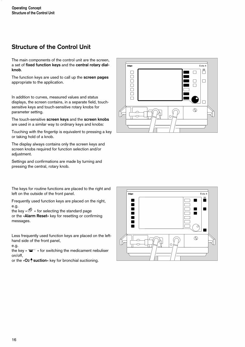
The main components of the control unit are the screen,a set of fixed function keys and the central rotary dial-knob.
The function keys are used to call up the screen pagesappropriate to the application.
In addition to curves, measured values and statusdisplays, the screen contains, in a separate field, touch-sensitive keys and touch-sensitive rotary knobs forparameter setting.
The touch-sensitive screen keys and the screen knobsare used in a similar way to ordinary keys and knobs:
Touching with the fingertip is equivalent to pressing a keyor taking hold of a knob.
The display always contains only the screen keys andscreen knobs required for function selection and/oradjustment.
Settings and confirmations are made by turning andpressing the central, rotary knob.
The keys for routine functions are placed to the right andleft on the outside of the front panel.
Frequently used function keys are placed on the right,e.g.the key »? « for selecting the standard pageor the »Alarm Reset« key for resetting or confirmingmessages.
Less frequently used function keys are placed on the left-hand side of the front panel,e.g.the key » « for switching the medicament nebuliseron/off, or the »O2 suction« key for bronchial suctioning.
Operating ConceptStructure of the Control Unit
16
D Evita 4
D Evita 4
17
Operating ConceptStructure of the Control Unit
On-Screen Controls
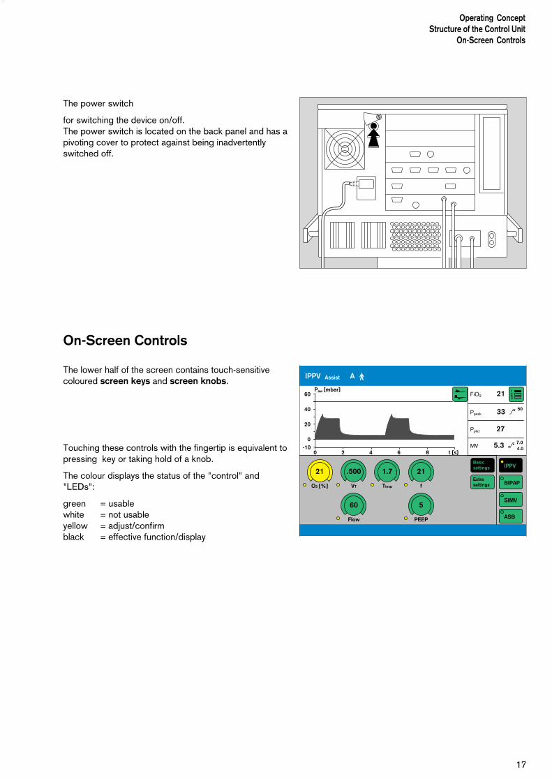
The power switch
for switching the device on/off.The power switch is located on the back panel and has apivoting cover to protect against being inadvertentlyswitched off.
On-Screen Controls
The lower half of the screen contains touch-sensitivecoloured screen keys and screen knobs.
Touching these controls with the fingertip is equivalent topressing key or taking hold of a knob.
The colour displays the status of the "control" and"LEDs":
green = usablewhite = not usableyellow = adjust/confirmblack = effective function/display
123
FiO2 21
Ppeak 33 > 50
Pplat 27
MV 5.3 _ 7.04.0
IPPV
BIPAP
SIMV
ASB
Extrasettings
Basicsettings
IPPV Assist A m
21
O2 [%]
.500
VT
1.7
Tinsp
21
f
60
Flow
5
PEEP
60
40
20
0-10
0 2 4 6 8 t [s]
Paw [mbar]
18
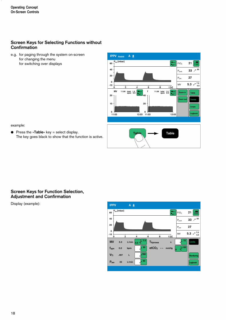
Screen Keys for Selecting Functions withoutConfirmation
e.g. for paging through the system on-screenfor changing the menufor switching over displays
example:
● Press the »Table« key = select display.The key goes black to show that the function is active.
Screen Keys for Function Selection,Adjustment and Confirmation
Display (example):
Operating ConceptOn-Screen Controls
123
FiO2 21
Ppeak 33 > 50
Pplat 27
MV 5.3 _ 7.04.0
Table
Trends
Loops
Logbook
Zoom out
Zoom in
IPPV Assist A m
60
40
20
0
20
10
0
-100 2 4 6
11:03 12:03
8 t [s]
Paw [mbar]
MV 11:06 total 1.5 spon 0.0
40
20
011:03 12:03
f 11:06 total 1.5 spon 0.0
Table Table
123
FiO2 21
Ppeak 33 > 50
Pplat 27
MV 5.3 _ 7.04.0
Limits
Logbook
Monitoring
IPPV A m
MV 5.3 L/min
fspn 0.0 bpm
TApnoea s
etCO2 – – mmHg
VTi .497 L
Paw 33 L/min
60
40
20
0-10
0 2 4 6 8 t [s]
Paw [mbar]
4.0 _ 7.0
_ 30
_ 15
0 _100
_780
_ 50

19
1 Touch the relevant screen key for the alarm limits,e.g.:
MV 2.3 L/min
The colour changes from green to yellow = settingfunction is set.
2 Turn the rotary knob = adjust the alarm limit.The value is displayed in the screen key.
3 Press the rotary knob = the colour changes fromyellow to green, and the set alarm limit is confirmedand effective.
To cancel the setting:
● Touch the screen key again
or
● touch another screen key.
Operating ConceptOn-Screen Controls
9.3
3.1
2
3
1
MV 2.3 L/min
20
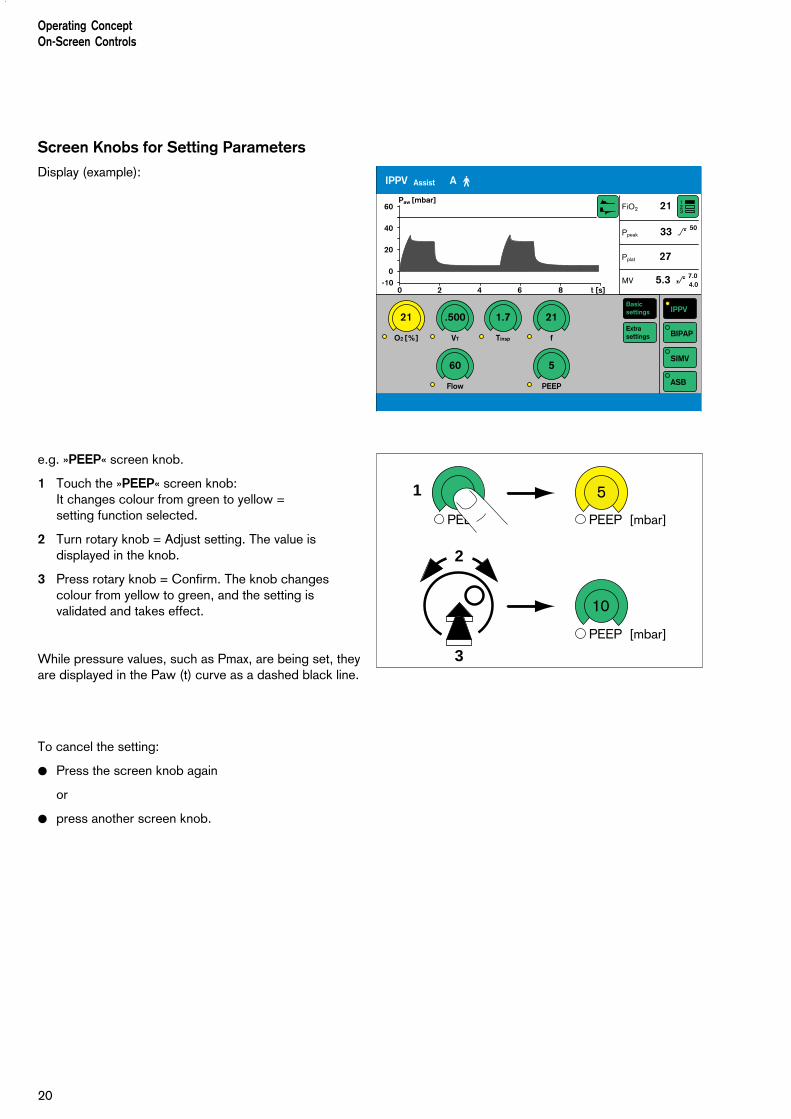
Screen Knobs for Setting Parameters
Display (example):
e.g. »PEEP« screen knob.
1 Touch the »PEEP« screen knob:It changes colour from green to yellow = setting function selected.
2 Turn rotary knob = Adjust setting. The value isdisplayed in the knob.
3 Press rotary knob = Confirm. The knob changescolour from yellow to green, and the setting isvalidated and takes effect.
While pressure values, such as Pmax, are being set, theyare displayed in the Paw (t) curve as a dashed black line.
To cancel the setting:
● Press the screen knob again
or
● press another screen knob.
123
FiO2 21
Ppeak 33 > 50
Pplat 27
MV 5.3 _ 7.04.0
IPPV
BIPAP
SIMV
ASB
Extrasettings
Basicsettings
IPPV Assist A m
21
O2 [%]
.500
VT
1.7
Tinsp
21
f
60
Flow
5
PEEP
60
40
20
0-10
0 2 4 6 8 t [s]
Paw [mbar]
Operating ConceptOn-Screen Controls
PEEP
5
10
PEEP [mbar]
PEEP [mbar]
1
3
2

21
Screen Pages
All the screen pages have the same structure, i.e. theircontents are always arranged in the same positions onthe screen:
Messages indicating ventilation modes and alarms,displays of measured values and curves, and helpfunctions, always appear in the same position on thescreen:
➀ The active ventilation mode/patient mode isdisplayed on the left-hand side of the top line. The ventilation mode is indicated by its abbreviation,e.g. BIPAP.
The patient mode is indicated by a symbol:A m for adultsP m for paediatric
In the case of spontaneous breathing activity by thepatient, a lung symbol ⁄ is briefly displayed asindicator.
➁ Curves are displayed in the upper left-hand quarter ofthe screen.
➂ The lower half of the screen shows curves andmeasured values or screen keys and screen knobs –depending which screen page is selected.
➃ Alarms are displayed on the right of the top line.
➄ Measured values are displayed in the upper right-hand quarter of the screen.
➅ Help functions appear in the bottom line of thescreen. On the right, Evita 4 provides settinginstructions. On the left, Evita 4 provides informationon the current status – this information can beaccessed by pressing key » «
The solid function keys to the right of the screen are usedto select the screen pages for the following specificapplication situations:
– Settings
– Alarm limits
– Measured values
– Special measurement procedures
– Calibration
– Configuration
Operating ConceptScreen Pages
Curves Measuredvalues
Curves or screen knobs Measuredvalues orscreen keys
Current ventilation mode/patient mode Alarms
Help functions
➀
➁➄
➃
➂
➅
D Evita 4

22
Screen page
For displaying the ventilation status
● Press »? « key.Display (example):
The standard page shows the ventilation situation at aglance – reduced to the most important measurementparameters and curves.
Four measured values are shown on the right, and twocurves on the left.
Other measured values and curves can be selected inthe standard page and all subsequent screen pages.
To select other measured value combinations:
● Touch screen key » « repeatedly.
To select other curves:
● Touch key » «, and touch the screen keycorresponding to the desired curve.
»Settings« screen
For displaying the setting parameters.
The bottom right-hand side of the screen contains thescreen keys for selecting the ventilation modes.
The screen key displayed in black (IPPV in the example)represents the currently activated ventilation mode.
The bottom left-hand side of the screen contains the on-screen rotary control knobs.
The values of the setting parameters are displayed in thescreen knobs relevant to the ventilation mode.
The user-definable start-up settings are marked by anarrow (j) on the scales of the screen knobs. See"Configuration" on page 107 onwards.
Changing the settings of an active ventilation mode
● Touch the appropriate screen knob, which will changecolour from green to yellow = setting functionenabled.
● Turn the rotary knob on the control unit = adjustmentof the value of setting in the screen knob.
● Press the rotary knob: the screen knob changescolour from green to yellow = the setting is confirmed(validated) and active.
Operating Concept Screen Pages
123
012
37 2
07 0
1337
207

23
Operating ConceptScreen Pages
D Evita 4
2 1
PEEP +
10
PASB
Selecting another ventilation mode and setting itsparameters
● Touch the appropriate screen key, e.g. »BIPAP«. Thekey changes colour from green to yellow, and theparameter setting page for BIPAP is displayed.
To set the parameters for BIPAP:
● Touch the screen knob, which changes colour fromgreen to yellow = adjustment function selected.
● Turn rotary knob = adjust value displayed in screenknob.
● Press rotary knob: the screen knob changes colourfrom yellow to green = setting validated and effective.
If the indicator "LED" next to a screen knob is illuminatedwhite, the knob setting will only be effective after the newventilation mode has been switched on (example: »PASB«knob).
If the indicator "LED" is illuminated yellow, the relevantknob setting is already active in the existing ventilationmode (example: »O2« knob).
The start-up values effective on switching on theventilator are marked on the relevant knob-scale with anarrow (j).Example: PASB = 0 mbar
● Press the rotary knob: the screen key changes colourfrom yellow to black = the ventilation mode is active.
For detailed instructions on setting the ventilation modes,please refer to page 49.
Cancel selection/setting
● Press the screen key or screen knob again.
or
● Press another screen key or another screen knob.
To quit a screen page:
1 Press »? « key = return to standard page
or
2 press any of the function keys next to the screen onthe right.
014
37 2
07

24
»Alarm limits« Screen Page
This page is used for:
Displaying the measured values and the correspondingalarm limits.
Setting the alarm limits.
Setting the monitoring function.
Displaying the logbook.
The alarm limits are grouped together in a field andcombined with a curve and four measured values.
Limits, monitoring and logbook are selected by thescreen keys on the right of the screen.The currently activated screen key is highlighted in black.
Displaying/Setting Alarm Limits
● Touch the »Limits« screen key. The screen key willchange to black.The monitored measured values will be displayed,together with their alarm limits:
Example:
MV 5.4 L/min
Left-hand screen key = lower alarm limit.Right hand screen key = upper alarm limit.
Set the alarm limit:
● Touch the relevant screen key.The key changes colour to yellow = adjustable.
● Turn the rotary knob = adjust value displayed in thekey.
● Press the dial-knob. The screen key changes colourto green = setting confirmed. The alarm limit is now effective.
For detailed operating instructions, please refer to page 77.
Operating ConceptScreen Pages
7.5
5.501
7 37
207
25
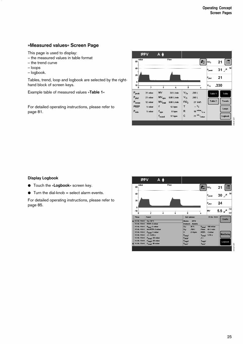
»Measured values« Screen Page
This page is used to display:– the measured values in table format– the trend curve– loops– logbook.
Tables, trend, loop and logbook are selected by the right-hand block of screen keys.
Example table of measured values »Table 1«
For detailed operating instructions, please refer to page 81.
Display Logbook
● Touch the »Logbook« screen key.
● Turn the dial-knob = select alarm events.
For detailed operating instructions, please refer to page 85.
Operating ConceptScreen Pages
018
37 2
0701
9 37
207

26
»Special Procedures« Screen Page
This page is used to display and perform the followingspecial measuring procedures:
– Intrinsic PEEPand– Occlusion pressure P 0.1
The desired special procedure is selected by theappropriate screen key on the right. The result of the lastspecial procedure is displayed.
Example: Intrinsic PEEP:
To start the special procedure:
● Touch the »Start« screen key.
For detailed operating instructions, please refer to page 93 and 94.
»Calibration« Screen Page
This page is used for calibrating– the O2 sensor– the Flow sensor– the CO2 sensor
● Select the desired sensor with the »O2«, »Flow« or»CO2« screen keys. Calibration starts as soon as the relevant key ispressed.
Evita 4 provides the necessary calibration instructions inthe Help Function line at the bottom of the screen.
For detailed operating instructions, please refer to page 97 et seq..
Operating ConceptScreen Pages
020
37 2
0702
1 37
207

»Configuration« Screen Page
For selecting/adjusting the following functions:
SoundSetting the volume of the alarm tone.
ScreenSelecting the displayed measured values.Selecting the displayed curves.Selecting the displayed trends.
VentilationSelecting ventilation modes.Selecting the patient mode.Selecting the initial setting.
System DefaultsSetting the external interface.Setting the time and date.Selecting the language and measurement units.Selecting service diagnosis.
For detailed operating instructions, see page 107.
Control Unit Location
To adapt to the situation of the ventilation location, thecontrol unit can be placed
either directly on the deviceorseparately, on a wall rail.
For detailed instructions on placing, see page 47.
Ergonomic Positioning
To ensure best viewing, free of reflections.
1 Hold down the blue segments on the right and left
and
2 at the same time, tilt the control unit to the desiredposition.
27
Operating ConceptScreen Pages
Control Unit Location
D Evita 4
1
1
2
2
022
37 2
07

28
Contents
Attaching components............................................................................30Fitting expiration valve...............................................................................30Fitting flow sensor.................................................................................... 30Fitting O2 sensor capsule......................................................................... 31
Note on Use of Heat and Moisture Exchanger (HME)............................ 31
Ventilation Adults and Children.............................................................. 32Connecting Aquapor humidifier................................................................ 32Connecting ventilation hoses.................................................................... 32Fitting temperature sensor........................................................................33Fitting CO2 cuvette and CO2 sensor........................................................ 34
Ventilating Infants................................................................................... 34Fitting bacterial filter................................................................................. 34Fitting humidifier and ventilation hose........................................................35
If using bacterial filters........................................................................... 35
Supply and Connections.........................................................................36Electrical power supply.............................................................................36Note on use of a socket strip for ancillary equipment.................................36Temporary interruption of power supply.................................................... 36Gas supply...............................................................................................37
Evita Remote (optional)........................................................................... 38Connection.............................................................................................. 38Note automatic self-test............................................................................ 39
Nurse call (optional).................................................................................40Technical Data......................................................................................... 40
Before Using for the First Time.............................................................. 41Selecting the language of the display texts................................................41
Device Check..........................................................................................42Before use on patient............................................................................... 42Performing device check.......................................................................... 43Checking the hose system for leaks..........................................................46
Positioning the control unit.....................................................................47To position the control unit on the wall rail.................................................47To position the control unit on the device.................................................. 47
29
PreparationContents
Preparation

The following instructions include:
– Equipment assembly.
– Electrical and gas connections.
– Setting the language for the display texts.
– Automatic device check with sensor calibration.
Attaching components● Always use properly prepared parts, see Preparing,
page 135.
Fitting the expiration valve
● Tilt the control unit upwards.
● Push the expiration valve as far as it will go into themounting. Check that it is properly engaged by gentlypulling the port.
Fitting the flow sensor
1 Push socket to left as far as it will go.
2 Fit flow sensor – with the probe facing towards theventilator – into the mounting and push it into thesocket as far as it will go.
Then:
3 Push flow sensor to the right as far as it will go intothe rubber lip of the expiration valve.
PreparationAttaching components
30
1
23

Fitting O2 sensor capsule
– when using the system for the first time
– when the display reads:O2 measurement inop
– when calibration can no longer be performed.
● Tilt control unit upwards.
1 Turn port downwards or to the left.
2 Use coin to loosen screw, and remove protectivecover.
3 Loosen the two knurled screws and open the sensorhousing.
4 Insert new sensor capsule.The sensor end with the circular tracks on thecontacts goes into the housing.
● Close the sensor housing securely with the twoknurled screws.
● Screw protective cover back in place.
● Dispose of the used sensor, please refer to page 144.
Note on the Use of Heat andMoisture Exchangers
The use of a heat and moisture exchanger (HME) in thepatient connection can increase breathing resistanceconsiderably.An increase in breathing resistance will lead to greatereffort in spontaneous breathing and greater trigger effortduring assisted ventilation. Under unfavourableconditions, an increase in breathing resistance can leadto an inadvertent PEEP.This breathing resistance in the patient hose systemcannot be monitored by the ventilator.
● Therefore you should regularly check the condition ofthe patient and the ventilator's measured values forvolume and resistance.
● Follow the Instructions for Use of the heat andmoisture exchanger (HME).
● Do not use the heat and moisture exchanger (HME) at the same time as a medicament nebuliser or humidifier!
1 2
31
PreparationAttaching components
Heat and Moisture Exchangers
3
3
4 3

Ventilation Adults and Children
From 100 mL tidal volume VT upwards
Patient mode: »Adults«
Do not use a heat and moisture exchanger at thesame time as a humidifier! Risk of increased breathing resistance due tocondensation.
Connecting Aquapor humidifier
Prepare Aquapor following the relevant Instructions forUse.
1 Hang Aquapor from rail by bracket and tightenscrews.
2 Insert elbow connector into Aquapor.
3 Insert the double connector into the elbow connector.
● Fill Aquapor bowl to the upper mark with distilledwater.
Connecting ventilation hoses
Do not use antistatic or conductive hoses*.
Depending on the desired position of the ventilator inrelation to the bed, the hinged arm can be fitted to eitherside of the machine.
Attachment on left-hand side:
4 Turn both ports to the left.
5 Turn Aquapor to the left.
The following description applies when the ventilationhoses have been attached on the left-hand side.
______________* DIN VDE 0750 Part 215:
The use of anti-static or electrically conductive material in thebreathing system of the lung ventilator is not considered conducive to greater safety. On the contrary, the use of these materialsincreases the danger of electric shock to the patient and of fire dueto the presence of oxygen.
23
1
PreparationVentilation Adults and Children
32
5
D Evita 4
4

1 Hang the hinged arm from the rail on the left-handside and tighten screws.
● Connect ventilation hoses, and note length of hose(metres).
2 Turn ports in direction of hoses.
3 Install water traps in vertical position.
● Connect the Y-piece, with the rubber sleeve of the Y-piece on the inspiratory side.
Fitting temperature sensor
4 Push sensor as far as it will go into the rubber sleeveon the inspiratory side of the Y-piece. Align the Y-piece so that the sensor is at the top.
5 Attach the sensor cable with hose clips.
6 Insert the probe of the temperature sensor into thesocket »Temp m « at the rear of the unit.
D
0,6m0,4m
0,6m
0,4m
0,6m
1
3
2
33
PreparationVentilation Adults and Children
45
6

Fitting CO2 cuvette and CO2 sensor (optional)
1 Fit the cuvette to the patient connection of the Y-piece, with the cuvette windows facing the side.
2 Push the CO2 sensor on to the cuvette, with the cabletrailing towards the unit.
● Insert the probe of the CO2 sensor in the socket»CO2 m « on the rear panel of the Evita 4.
Ventilating Infants
Up to 300 mL tidal volume VT
Patient mode »Paediatrics«
Do not use a heat and moisture exchanger at thesame time as a humidifier!Risk of increased breathing resistance because ofcondensation.
Fitting bacterial filter
● Fit the bacterial filter to the inspiratory port.
1
2
PreparationVentilation Adults and Children Ventilating Infants
34
D Evita 4

Fitting humidifier and ventilation hoses
● Prepare the "Fisher & Paykel MR 730" breathing gas humidifier as specified in the Instructions for Useof the humidifier. Use the relevant hose set K (paediatric).
● Clamp the humidifier to the stand under the apparatusand screw firmly into place.
● Clamp the articulated arm to the left-hand rail andscrew firmly into place.
● Fit the ventilation hoses.Check the hose lengths (metres).
● Fit the water trap in the vertical position.
Do not place any liquid containers above or on top of Evita 4!Any leaking or spilled liquid could causemalfunctions!
If using bacterial filtersThe use of expiratory bacterial filters on the ventilator isnot recommended.
However, if bacterial filters are nevertheless used on theexpiration side, an undesirable increase in breathingresistance is possible.Especially during medicament nebulisation andhumidifying, the resistance of the bacterial filter mayincrease gradually. For the patient, the effect may beincreased breathing effort and intrinsic PEEP.
An intrinsic PEEP can be recognised by the fact that theexpiratory flow does not return to "0" before the end ofexpiration.
If PEEP is unacceptably high, the unit signals the »PEEP high« alarm.
● Check the bacterial filter and replace it if it is thecause of the PEEP.
35
PreparationVentilating Infants
If using bacterial filters
D Evita 4
0,6m0,6m
0,4m
1,1m

Supply and Connections
Electrical power supply
The ventilator is designed for a mains voltage of:
either : 220 V to 240 Vor : 100 V to 127 V
● Insert the plug in the mains socket.
For operation with DC power unit and external battery(option)
either : 12 V or : 24 V
● Connect the external battery by cable.
Note on the use of a socket strip for ancillaryequipment
Connecting other devices to the same extension socketstrip may, in the event of earth failure, cause the currentleakage to the patient to increase beyond the permissiblevalues. In this case, the risk of electric shock cannot beeliminated.
Temporary interruption of power supply
e.g. if hospital reserve power supply is activated.
Without the 12/24 V DC power unit:
During a power interruption, Evita 4 outputs a continuousalarm tone for max. 2 minutes.The duration of this alarm tone may be shorter if Evita 4was switched on for less than 15 minutes.
Evita 4 tolerates power interruptions shorter than 10 milli-seconds – without any effect on ventilation. In the case of power interrupts lasting longer then 10 milliseconds, the machine restarts with a short self-test lasting about 4 seconds – ventilation is continuedwith the same values that were set before the powerinterruption. If a lower alarm limit has been set for the minute volume,the MV low alarm is activated until the measured valuehas risen above the lower alarm limit.
With 12/24 V DC power unit (option):
Follow Instructions for Use of Evita 4 DC option (DC power supply).
PreparationSupply and Connections
36

Gas supply
● Screw the connecting hoses for medical air andoxygen to the back panel of Evita 4 and insert theirprobes into the terminal units.
The compressed gases must be dry and free fromdust and oil. Gas pressure must be 3 to 6 bar.
37
PreparationSupply and Connections
Air O2
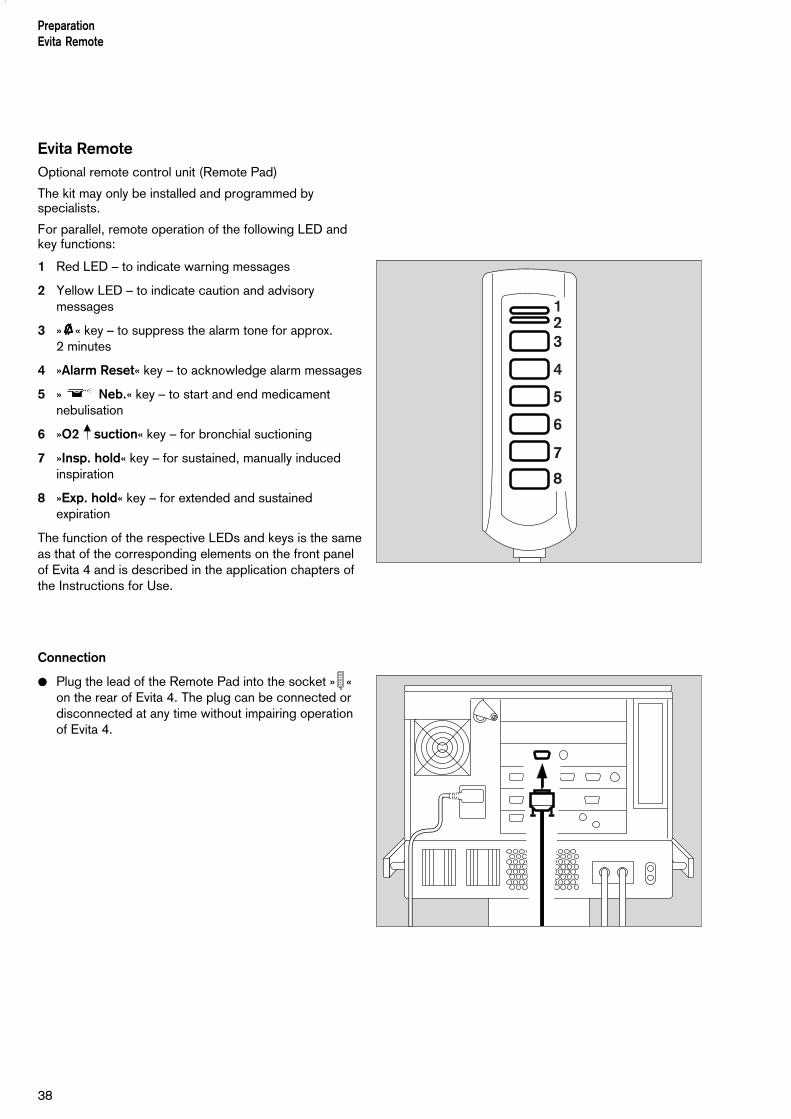
Evita RemoteOptional remote control unit (Remote Pad)
The kit may only be installed and programmed byspecialists.
For parallel, remote operation of the following LED andkey functions:
1 Red LED – to indicate warning messages
2 Yellow LED – to indicate caution and advisorymessages
3 »gggg« key – to suppress the alarm tone for approx. 2 minutes
4 »Alarm Reset« key – to acknowledge alarm messages
5 » Neb.« key – to start and end medicamentnebulisation
6 »O2 suction« key – for bronchial suctioning
7 »Insp. hold« key – for sustained, manually inducedinspiration
8 »Exp. hold« key – for extended and sustainedexpiration
The function of the respective LEDs and keys is the sameas that of the corresponding elements on the front panelof Evita 4 and is described in the application chapters ofthe Instructions for Use.
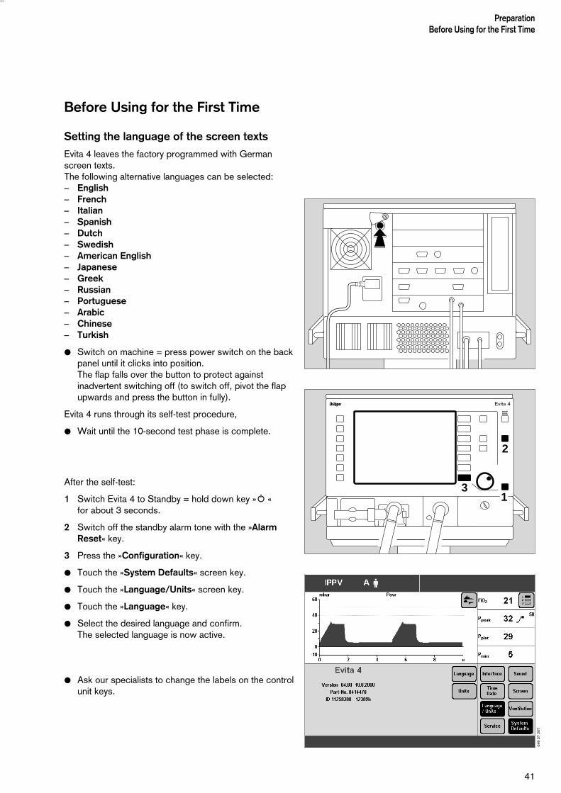
Connection
● Plug the lead of the Remote Pad into the socket » «on the rear of Evita 4. The plug can be connected ordisconnected at any time without impairing operationof Evita 4.
123
4
6
5
7
8
38
PreparationEvita Remote

● Hook holder onto a standard rail and clamp into place.
● Hang Remote Pad into holder from above.
Note automatic self-test
– when connecting the Remote Pad to Evita 4 while thelatter is switched on
or
– when switching on Evita 4 after connecting theRemote Pad.
● Do not press any keys on the Remote Pad.
● All LEDs on the Remote Pad light up for 5 seconds:– Red LED– Yellow LED– Yellow LEDs in the keys
● The Remote Pad is tested by Evita 4. An advisorymessage is output if a fault is detected, see page 127"Troubleshooting".
39
PreparationRemote Pad

Nurse call(optional)
Socket on the rear of Evita 4 for connecting alarm signalsto a central alarm station in the hospital.
● The kit may only be installed by specialists.
● The 6-pin round DIN plug (female connector) must beconnected to the lead for the central alarm station inthe hospital by a specialist.
Connection 3-5 makes and the nurse call is activated assoon as Evita 4 signals an alarm.
● Plug the connector into the » « socket on the rearand screw into place.
● Check correct operation of connected nurse callsystem.
Only alarm messages of the highest priority (see page 78) are transmitted via nurse call.
Warning messages are displayed in the top line of thescreen in red and with three exclamation marks, seepage 78. Caution and advisory messages are nottransmitted. The nurse call is also activated when theinternal loudspeaker in the ventilator is defective.
Background: The hospital connections to the centralalarm typically use only one channel. The electronics fornurse call consequently also uses only one channel.
Technical Data
Floating DC contact
Input voltage Max. 40 V =Input current Max. 500 mASwitching capacity Max. 15 W
5
3
1
40
PreparationNurse call (optional)
1 5
3
Connection of a nurse call does not relieve staff oftheir duty to check the monitoring on the Evita 4screen at regular intervals.
● Screen displays must be checked regularly.
A fault in any of the components in the link betweennurse call and central hospital alarm system (e.g. inthe electronics for nurse call in Evita, in the Evitapower supply, or in the alarm generator of the centralhospital alarm system) may result in failure of thenurse call.
Before Using for the First Time
Setting the language of the screen texts
Evita 4 leaves the factory programmed with Germanscreen texts.The following alternative languages can be selected:– English – French – Italian – Spanish – Dutch – Swedish – American English – Japanese– Greek– Russian– Portuguese– Arabic– Chinese– Turkish
● Switch on machine = press power switch on the backpanel until it clicks into position.The flap falls over the button to protect againstinadvertent switching off (to switch off, pivot the flapupwards and press the button in fully).
Evita 4 runs through its self-test procedure,
● Wait until the 10-second test phase is complete.
After the self-test:
1 Switch Evita 4 to Standby = hold down key »O « for about 3 seconds.
2 Switch off the standby alarm tone with the »AlarmReset« key.
3 Press the »Configuration« key.
● Touch the »System Defaults« screen key.
● Touch the »Language/Units« screen key.
● Touch the »Language« key.
● Select the desired language and confirm.The selected language is now active.
● Ask our specialists to change the labels on the controlunit keys.
41
PreparationBefore Using for the First Time
D Evita 4
2
31
049
37 2
07

Device Check
Before use on patient
Immediately before using on the patient, check that themachine is working properly and is ready for operation.Evita 4 supports this »device check« by means of a built-in checklist that guides the user through the test in adialogue mode.
The following functions are performed during this devicecheck:
– Checking that the machine assembly is complete,
– Testing the alarm tone,
– Testing the expiratory valve,
– Testing the air-O2 change-over valve,
– Testing the safety valve,
– Calibrating the flow sensor,
– Calibrating the O2 sensor,
– Calibrating the CO2 sensor,
– Testing the leakproofing of the hose system,
– Checking the compliance of the hose system.
The test results obtained from this device check and thecalibration and zero-checking values of the sensorsremain stored until the next calibration – even if thedevice is switched off.
If the hose system, type of humidification or patient modeis changed after performing the device check, theleakproofing test must be repeated before startingoperation.
Preparing the adult test lung 84 03 201
for the adult hose system
The test lung consists of an elbow connector forconnection to the Y-piece, a 7 mm diameter catheterconnection for simulating the resistance of the airwaysand a 2 litre breathing bag to simulate compliance.
● Overextended breathing bags must not be used asthey may cause artefacts during the device check!
● The elbow connector must not be plugged into thepatient connection of the Y-piece until directed byEvita 4.
PreparationDevice Check
42

Preparing the child test lung 84 09 742
for the paediatric hose set
The test lung consists of a tracheal tube CH 12 tosimulate the resistance of the airways and a smallbellows to simulate compliance.
● Only insert the elbow connector into the Y-piecewhen Evita 4 advises you to do so on the screen.
Performing the device check
● Switch on the machine = press power switch on theback panel until it clicks into position.
Evita 4 runs through its self-test procedure.
● Wait until the 10-second test phase has beencompleted.
After the self-test:
1 Switch Evita 4 to standby = Hold down key »O « for about 3 seconds.
2 Switch off the standby alarm tone with the »Alarm Reset« key.
● Touch the »Device check« screen key.
PreparationDevice Check
43
D Evita 4
2
1

Display:
Before starting the check, enter the type of humidifierselected:
– Active humidifier, e.g. Dräger Aquaporor
– HME/Filter (artificial nose)
If the type of humidifier is known, Evita 4 can take thetemperature and moisture situation into account whenmeasuring the volume parameters.
● Touch the »Humid.« screen key.
Display:
● Touch the »Active Humid.« screen key
or
● Touch the »HME/Filter« screen key.
● Confirm selection = press rotary knob.
The selected type of humidifier is indicated by a yellowLED.
The humidifier selection is saved and remains effectiveeven when the equipment is switched on again.
If the type of humidifier is changed and has to bereselected on the screen, the following test steps areshown to be invalid (– –) after the device check:
– Humidification
– Air tight check
The operator is prompted to repeat the device check forthese two steps.
Start the check procedure:
● Press the »Check« screen key.
Evita 4 starts running through the dialogue-orientedcheck.The check procedure is semi-automatic.During the device check, the user is instructed by Evita 4to perform specific actions on the device.
44
PreparationDevice Check
054
37 2
0705
5 37
207

The following tests are performed during the devicecheck:
– Correct operation of auxiliary and power failure alarms
– Seating and clear passage of the expiratory valve
– Seating of the flow sensor
– Seating of the neonate flow sensor (if "NeoFlow" option is installed)
– Type of humidifier
– Completeness of hose system
– Function of the air-O2 changeover valve
– Function of the safety valve
– Gas supply
– Calibration of the flow sensor
– Calibration of the neonate flow sensor (if "NeoFlow" option is installed)
– Calibration of the O2 sensor
– Leakproofing of the hose system
On completion of the device check, a checklist isdisplayed on the screen to show the results of the check.
Correct result : ✓ Incorrect result : FCheck not performed : – –
In the event of incorrect results, e.g. if the hose system isnot sufficiently leakproof:
● Eliminate the cause of the fault
● Touch the »Repeat check« screen key
Only the tests with incorrect results are repeated.
After successful completion of the device check, Evita 4 is ready for operation.
Either:
● immediately start up Evita 4 by pressing key »O «
or:
● leave Evita in standby mode
or:
● switch off Evita for later use. Switch on back panel = pivot flap to the side andpress button in fully and release.
PreparationDevice Check
45
D Evita 4
Checking the hose system for leaks
The hose system is tested for leaks during the devicecheck but must also be monitored independently of thedevice check, e.g. after changing the hose system.
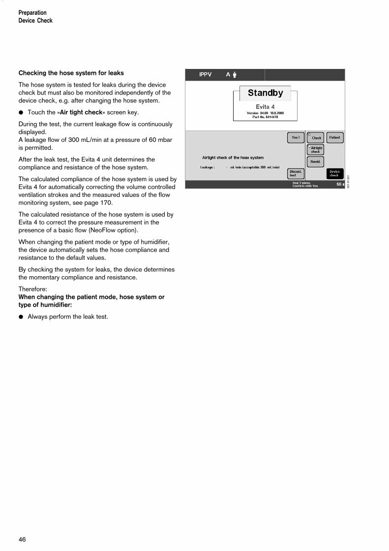
● Touch the »Air tight check« screen key.
During the test, the current leakage flow is continuouslydisplayed.A leakage flow of 300 mL/min at a pressure of 60 mbaris permitted.
After the leak test, the Evita 4 unit determines thecompliance and resistance of the hose system.
The calculated compliance of the hose system is used byEvita 4 for automatically correcting the volume controlledventilation strokes and the measured values of the flowmonitoring system, see page 170.
The calculated resistance of the hose system is used byEvita 4 to correct the pressure measurement in thepresence of a basic flow (NeoFlow option).
When changing the patient mode or type of humidifier,the device automatically sets the hose compliance andresistance to the default values.
By checking the system for leaks, the device determinesthe momentary compliance and resistance.
Therefore: When changing the patient mode, hose system ortype of humidifier:
● Always perform the leak test.
PreparationDevice Check
46
057
37 2
07

Positioning the control unit● Do not lean the control unit.
When changing, lay it on its back.
To position the control unit on the wall rail
1 Hold down the segments on the right and left, and tiltthe control unit fully downwards.
2 Hold down the release buttons on the left and right,and remove the control unit from the Evita 4 mounting.
● Uncoil the cable as far as necessary.
● Clip the control unit to the wall rail and
3 lock in place = pull down the latch situated beneaththe bracket and turn it in the direction of the wall rail.
1 Hold down the segments on the right and left and atthe same time tilt the control unit to the desiredposition.
To position the control unit on the device
● Hold down the segments on the right and left and tiltthe control unit fully downwards.
● Release the control unit = turn the latch away from thewall rail and lift the control unit off the rail.
● Coil the cable.
● Hang the control unit in the Evita 4 mounting so that itrests in position.
● Hold down the segments on the right and left, and atthe same time tilt the control unit to the optimalposition.
1
1
47
PreparationPositioning the control unit
2
2
3

48

Selecting/Quitting Standby Mode............................96
Calibration................................................................ 97Calibrating O2 sensor................................................ 97Calibrating flow sensor.............................................. 98External flow source...................................................99Checking/calibrating CO2 sensor............................ 100CO2 zero checking..................................................100Testing CO2 calibration with test filter......................102Testing CO2 calibration with test gas.......................103Calibrating CO2 sensor........................................... 105Resetting CO2 calibration........................................106
Contents
Starting up................................................................50Switching on..............................................................50
Patient mode............................................................ 50Selecting the patient mode.........................................51Entering the ideal body weight................................... 51Select the previous settings....................................... 51Starting ventilation..................................................... 52
Setting Ventilation Modes........................................ 53IPPV..........................................................................53SIMV, SIMV/ASB...................................................... 57BIPAP, BIPAP/ASB...................................................60BIPAPAssist................................................................62CPAP, CPAP/ASB....................................................63MMV, MMV/ASB.......................................................65APRV........................................................................ 67
Independent Lung Ventilation ILV............................ 69Preparation................................................................69Setting the master and slave device........................... 71
Apnoea ventilation....................................................76
Setting Alarm Limits................................................. 77
In the Event of an Alarm...........................................78Cancel alarm tone......................................................79Information J ............................................................ 79
Displaying Curves and Measured Values.................80Displaying measured values....................................... 81Trends.......................................................................82Loops........................................................................ 83Reference curve displays........................................... 83Single stroke displays................................................ 83Zoom loops (optional)................................................ 83Display loops in the upper graphic area......................84Logbook.................................................................... 85Screen freeze............................................................ 86
Special Functions.....................................................87Manual inspiration......................................................87Exspiration Hold.........................................................87Medicament nebulisation............................................88Oxygen enrichment for bronchial suction....................91Special measurement procedure: intrinsic PEEP........ 93Special measurement procedure: occlusion pressure P 0.1...........................................................94Shut-down.................................................................95
49
OperationContents
Operation

Starting up
Switching on
● Push in power switch on back panel until it clicks intoplace = ON.The flap comes down over the switch to prevent itbeing inadvertently switched off.
Evita 4 runs a self-test.
● Wait until the 10-second test phase is complete.
Evita 4 always begins ventilation with the start-up valuesmarked by an arrow on the on-screen knobs.To select these start-up values, please refer to pages 119 et seq..After power cuts and after standby mode, the settingsvalid immediately before the interruption of operationremain in use.
Patient mode
After switching on, Evita 4 displays a choice of patientmodes:
– »Adults« = adult patients
– »Paed.« = children
– »Neo.« = neonates(when using the "NeoFlow" option)
– »prev. patient« = previous patient
The device also asks the user to enter the weight of thepatient (ideal body weight).
Example:
Adult ventilation
With this information, Evita 4 defines the adjustmentranges and the start-up values of the ventilationparameters.
The starting procedure, with selection of the patientmode, can be configured by the user, see Configurationon page 107 onwards.
50
OperationStarting up
062
37 2
07

The screen key »prev. patient« can be used to restorethe specific patient settings, including alarm limits andmonitoring status, effective before switching off thedevice.
Example:
Previous patient
The previous modes are displayed in the status line:
– Previous ventilation mode– Previous patient mode– Previous application mode (tube or mask for
optional NIV)
The key »prev. patient« is not displayed by Evita 4following a loss of data or removal of a previously usedoption (e.g. NeoFlow), thus preventing restoration of theprevious setting.Restoration of the previous setting is similarly preventedby Evita 4 if it was configured in such a way beforeswitching off that the former patient mode is no longeravailable.
Selecting the patient mode
if configured
EITHER
● the »Adults« key or the »Paed.« key or the »Neo.« key (NeoFlow option) and
enter the ideal body weight
if configured
With the ideal body weight, Evita 4 determines the start-up settings of the ventilation parameters. The start-up value is marked on the relevant screen knob by an arrow ( j).
● Touch the screen knob.
● Enter the ideal body weight [kg] with the manual dial-knob = turn rotary knob.
● Confirm the setting = press rotary knob.
OR
Select the previous settings
● Touch the key »prev. patient«.
● Confirm = press rotary knob.
51
OperationStarting up
063
37 2
0706
2 37
207

Starting ventilation
● Press the rotary knob again.Evita 4 starts ventilation with the ventilation modeconfigured by the user.
The machine is factory-set to IPPV.
Evita 4 displays the »Settings« screen page. The user can check and correct the settings on thescreen.
OperationStarting up
52
065
37 2
07

53
OperationSetting Ventilation Modes
Setting Ventilation Modes
The ventilation modes IPPV, BIPAP, SIMV and ASB arealready configured in the unit. If other ventilation modesare used, please refer to page 113 "Selecting ventilationmodes".
IPPVIntermittent Positive Pressure Ventilation
Volume-controlled ventilation with fixed, mandatoryminute volume MV and user-adjusted tidal volume VT and frequency f.
For patients having no spontaneous breathing.
Set the pattern of ventilation for IPPV with the ventilationparameters:
Tidal volume »VT«
Insp. Flow »Flow«
Frequency »f«Inspiration time »Tinsp«
O2 concentration »O2«Positive end-expiratory pressure »PEEP«
––––––––––––––––––––––––––––––––––––––––––––––––To set:
● Touch the relevant screen knob.
● Adjust value = turn rotary knob.
● Confirm setting = push rotary knob.
––––––––––––––––––––––––––––––––––––––––––––––––
Paw
Flow
Tinsp Te
Pplat
Insp.pause
Pmax(configu-rable)
PEEP
1f
Insp. flow
t
t
065
37 2
07

IPPV can be expanded by the following ventilationparameters:
Flowtrigger (IPPV Assist) – for synchronisation withattempted spontaneous breathing by the patient.By switching on the flow trigger and setting the triggerlevel, the mandatory strokes are synchronised with thepatient's spontaneous breathing attempts.Spontaneous breathing activity by the patient is indicatedby the brief display of a lung symbol instead of the usualsymbol for the patient mode.
Sigh – for prophylactic treatment of atelectasis.Atelectasis can be prevented by switching on the Sighfunction and setting the sigh in the form of an intermittentPEEP. When the Sigh function is activated, the end-expiratorypressure increases for two ventilation strokes every 3 minutes by the set value of the intermittent PEEP.
AutoFlow – for automatic regulation of the inspirationflow. With AutoFlow *, the inspiration flow is decelerated andregulated, so that at the selected tidal volume VT with thecurrent lung compliance a minimum airway pressure isreached and pressure peaks are avoided. Evita 4 delivers additional inspiration flow if and when thepatient breathes in – limited by the alarm limit VTi >The patient can also breathe out during the inspiratoryplateau phase. The inspiratory pressure is limited by the Paw > alarmlimit.
● Set the alarm limits MV < and MV > in order toavoid excessive or insufficient flow following rapidchanges in compliance.
––––––––––––* Please refer to page 160 for a detailed description of AutoFlow
and PLV.
OperationSetting Ventilation Modes
54
068
37 2
0706
9 37
207

55
OperationSetting Ventilation Modes
––––––––––––––––––––––––––––––––––––––––––––––––To set:
● Touch the »Extra settings« screen key.
● Touch the screen key corresponding to the desired function.
For Flow Trigger and Sigh:
● Touch the appropriate screen key.
● Adjust the desired value = turn the rotary knob● Confirm the desired setting = press the rotary knob
● Switch on the function = touch the »On« screen button and press the rotary knob.
––––––––––––––––––––––––––––––––––––––––––––––––
IPPV can be configured for the additional ventilationparameter Pmax.Selecting »Pmax pressure limiting«, see page 115.
Pressure Limited Ventilation (PLV)* – for manuallylimiting pressure peaks using the Pmax pressure limit.The tidal volume remains constant as long as the pres-sure curve shows a plateau and the inspiratory flow curveshows a brief flow pause between inspiration andexpiration.
● To set the "Pmax" pressure limit, please refer to page 115.
The value of Pmax is displayed as a dashed blue line inthe Paw (t) curve.
The "Inconstant volume" alarm is always active. It istriggered automatically if the tidal volume VT can nolonger be applied.
This visual and audible alarm can be suppressed with the »Alarm Reset« key until the cause of the alarm isremedied.
––––––––––––* Please refer to page 160 for a detailed description of AutoFlow
and PLV.
070
37 2
0707
1 37
207

56
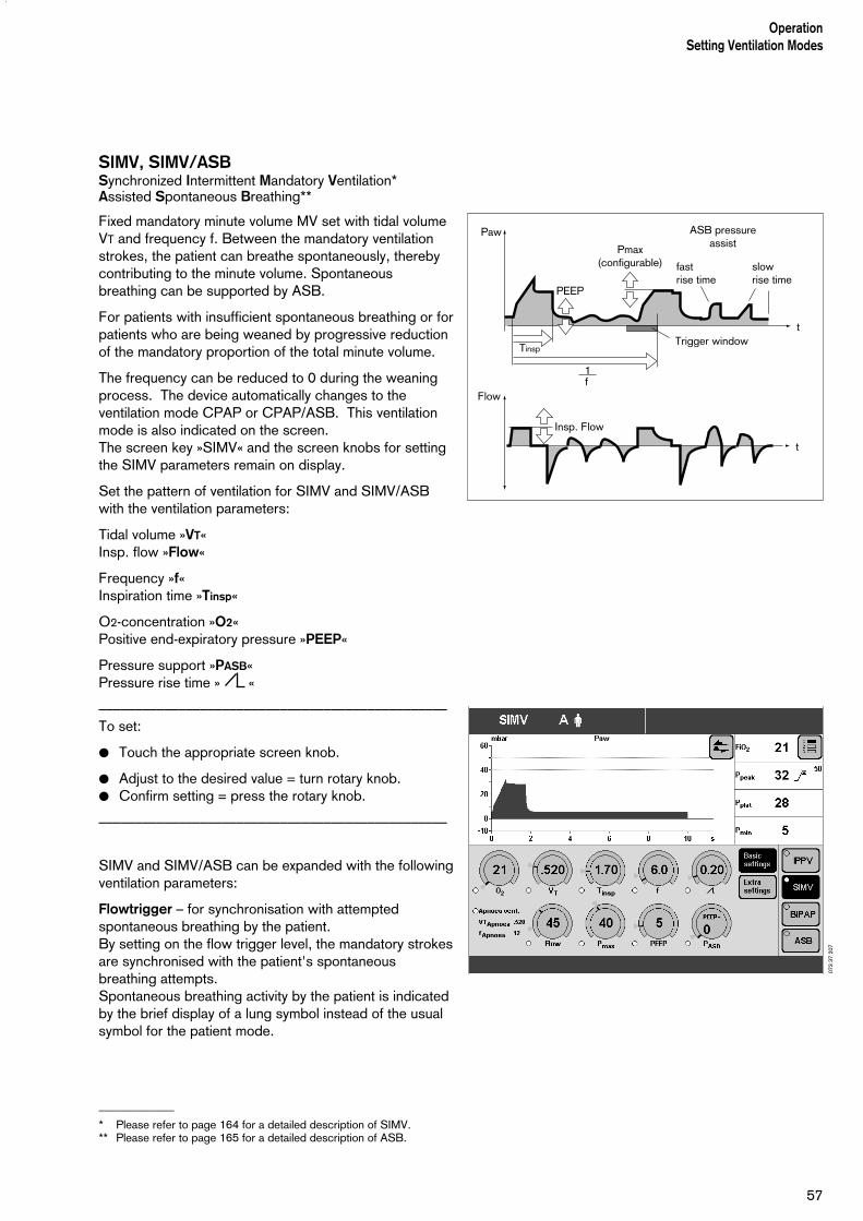
SIMV, SIMV/ASBSynchronized Intermittent Mandatory Ventilation*Assisted Spontaneous Breathing**
Fixed mandatory minute volume MV set with tidal volumeVT and frequency f. Between the mandatory ventilationstrokes, the patient can breathe spontaneously, therebycontributing to the minute volume. Spontaneousbreathing can be supported by ASB.
For patients with insufficient spontaneous breathing or forpatients who are being weaned by progressive reductionof the mandatory proportion of the total minute volume.
The frequency can be reduced to 0 during the weaningprocess. The device automatically changes to theventilation mode CPAP or CPAP/ASB. This ventilationmode is also indicated on the screen.The screen key »SIMV« and the screen knobs for settingthe SIMV parameters remain on display.
Set the pattern of ventilation for SIMV and SIMV/ASBwith the ventilation parameters:
Tidal volume »VT«Insp. flow »Flow«
Frequency »f«Inspiration time »Tinsp«
O2-concentration »O2«Positive end-expiratory pressure »PEEP«
Pressure support »PASB«Pressure rise time » «
––––––––––––––––––––––––––––––––––––––––––––––––To set:
● Touch the appropriate screen knob.
● Adjust to the desired value = turn rotary knob.● Confirm setting = press the rotary knob.
––––––––––––––––––––––––––––––––––––––––––––––––
SIMV and SIMV/ASB can be expanded with the followingventilation parameters:
Flowtrigger – for synchronisation with attemptedspontaneous breathing by the patient.By setting on the flow trigger level, the mandatory strokesare synchronised with the patient's spontaneousbreathing attempts.Spontaneous breathing activity by the patient is indicatedby the brief display of a lung symbol instead of the usualsymbol for the patient mode.
_____________
* Please refer to page 164 for a detailed description of SIMV.** Please refer to page 165 for a detailed description of ASB.
57
OperationSetting Ventilation Modes
Paw
Flow
Tinsp
Pmax(configurable)
PEEP
fastrise time
slowrise time
ASB pressureassist
Trigger window
f
Insp. Flow
t
t
1
073
37 2
07
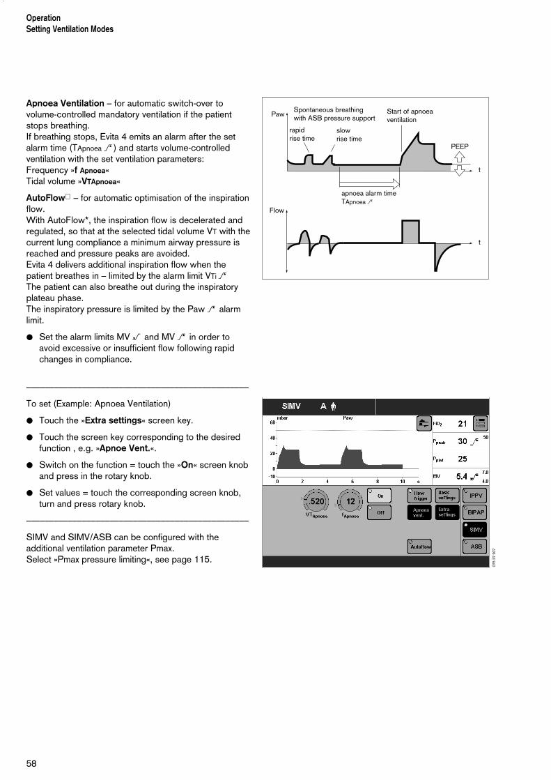
Apnoea Ventilation – for automatic switch-over tovolume-controlled mandatory ventilation if the patientstops breathing.If breathing stops, Evita 4 emits an alarm after the setalarm time (TApnoea > ) and starts volume-controlledventilation with the set ventilation parameters:Frequency »f Apnoea«Tidal volume »VTApnoea«
AutoFlow – for automatic optimisation of the inspirationflow. With AutoFlow*, the inspiration flow is decelerated andregulated, so that at the selected tidal volume VT with thecurrent lung compliance a minimum airway pressure isreached and pressure peaks are avoided. Evita 4 delivers additional inspiration flow when thepatient breathes in – limited by the alarm limit VTi >The patient can also breathe out during the inspiratoryplateau phase. The inspiratory pressure is limited by the Paw > alarmlimit.
● Set the alarm limits MV < and MV > in order toavoid excessive or insufficient flow following rapidchanges in compliance.
––––––––––––––––––––––––––––––––––––––––––––––––
To set (Example: Apnoea Ventilation)
● Touch the »Extra settings« screen key.
● Touch the screen key corresponding to the desiredfunction , e.g. »Apnoe Vent.«.
● Switch on the function = touch the »On« screen knoband press in the rotary knob.
● Set values = touch the corresponding screen knob,turn and press rotary knob.
––––––––––––––––––––––––––––––––––––––––––––––––
SIMV and SIMV/ASB can be configured with theadditional ventilation parameter Pmax.Select »Pmax pressure limiting«, see page 115.
58
OperationSetting Ventilation Modes
Paw
Flow
apnoea alarm timeTApnoea >
Start of apnoeaventilation
t
t
PEEP
rapidrise time
slowrise time
Spontaneous breathingwith ASB pressure support
075
37 2
07

Pressure Limited Ventilation (PLV)* – for manuallylimiting pressure peaks using the Pmax pressure limit.The tidal volume remains constant as long as thepressure curve shows a plateau and the inspiratory flowcurve shows a brief flow pause between inspiration andexpiration.
● To set the "Pmax" pressure limit, please refer to page 115.
The value of Pmax is displayed as a dashed blue line inthe Paw (t) curve.
The "Inconstant volume" alarm is always active. It istriggered automatically if the tidal volume VT can nolonger be applied.
This visual and audible alarm can be suppressed with the»Alarm Reset« key until the cause of the alarm isremedied.
––––––––––––* Please refer to page 160 for a detailed description of AutoFlow
and PLV.
59
OperationSetting Ventilation Modes
076
37 2
07

BIPAP, BIPAP/ASBBiphasic Intermittent Positive Airway PressureAssisted Spontaneous Breathing
Pressure-controlled ventilation combined with freespontaneous breathing during the complete breathingcycle, and adjustable pressure support at CPAP level. The mandatory proportion of the total minute volume MVis set with inspiratory pressure Pinsp above PEEP andFrequency f.
For a range of patients, from those unable to breathespontaneously to those breathing spontaneously beforeextubation. Patients are weaned off the ventilator byprogressive reduction of the mandatory proportion of theoverall minute volume MV and reduction of the pressuresupport PASB.
The frequency can be reduced to 0 during the weaningprocess. The device automatically changes to theventilation mode CPAP or CPAP/ASB. This ventilationmode is also indicated on the screen.The screen key »BIPAP« and the screen knobs for settingthe BIPAP parameters remain on display.
Set the pattern of ventilation for BIPAP and BIPAP/ASBwith the ventilation parameters:
Inspiration pressure »Pinsp«
Frequency »f«Time »Tinsp«
O2 concentration »O2«Positive end-expiratory pressure »PEEP«
Pressure support »PASB«Pressure rise time » «
The inspiration pressure »Pinsp« can be reduced to thePEEP level, in which case the ventilation patterncorresponds to CPAP or CPAP/ASB.
The inspiration pressure »Pinsp« is set as an absolutevalue. Pressure support »PASB« is set relative to thePEEP level.
––––––––––––––––––––––––––––––––––––––––––––––––To set:
● Touch the appropriate screen knob.
● Adjust to the desired value = turn rotary knob.● Confirm setting = press the rotary knob.
––––––––––––––––––––––––––––––––––––––––––––––––
OperationSetting Ventilation Modes
60
Paw
Flow
Pinsp
PEEP
slowrise time
fastrise time
t
t
Tinsp
fastrise time
slowrise time
ASBpressure assist
Trigger window for insp. and exp. synchronisation
f1
without spontaneous breathing
with spontaneous breathing
078
37 2
07
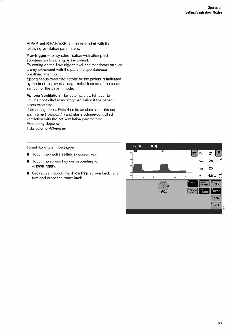
BIPAP and BIPAP/ASB can be expanded with thefollowing ventilation parameters:
Flowtrigger – for synchronisation with attemptedspontaneous breathing by the patient.By setting on the flow trigger level, the mandatory strokesare synchronised with the patient's spontaneousbreathing attempts.Spontaneous breathing activity by the patient is indicatedby the brief display of a lung symbol instead of the usualsymbol for the patient mode.
Apnoea Ventilation – for automatic switch-over tovolume-controlled mandatory ventilation if the patientstops breathing.If breathing stops, Evita 4 emits an alarm after the setalarm time (TApnoea > ) and starts volume-controlledventilation with the set ventilation parameters:Frequency »fApnoea«Tidal volume »VTApnoea«
––––––––––––––––––––––––––––––––––––––––––––––––To set (Example: Flowtrigger)
● Touch the »Extra settings« screen key.
● Touch the screen key corresponding to»Flowtrigger«.
● Set values = touch the »FlowTrig« screen knob, andturn and press the rotary knob.
––––––––––––––––––––––––––––––––––––––––––––––––
61
OperationSetting Ventilation Modes
079
37 2
07
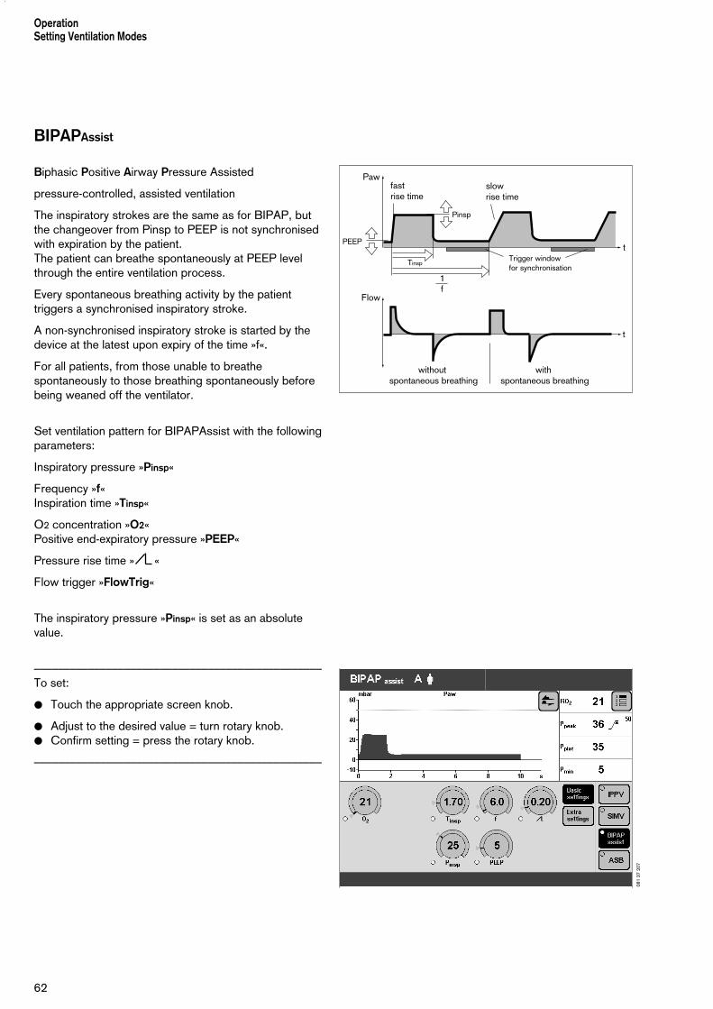
BIPAPAssist
Biphasic Positive Airway Pressure Assisted
pressure-controlled, assisted ventilation
The inspiratory strokes are the same as for BIPAP, butthe changeover from Pinsp to PEEP is not synchronisedwith expiration by the patient.The patient can breathe spontaneously at PEEP levelthrough the entire ventilation process.
Every spontaneous breathing activity by the patienttriggers a synchronised inspiratory stroke.
A non-synchronised inspiratory stroke is started by thedevice at the latest upon expiry of the time »f«.
For all patients, from those unable to breathespontaneously to those breathing spontaneously beforebeing weaned off the ventilator.
Set ventilation pattern for BIPAPAssist with the followingparameters:
Inspiratory pressure »Pinsp«
Frequency »f«Inspiration time »Tinsp«
O2 concentration »O2«Positive end-expiratory pressure »PEEP«
Pressure rise time » «
Flow trigger »FlowTrig«
The inspiratory pressure »Pinsp« is set as an absolutevalue.
––––––––––––––––––––––––––––––––––––––––––––––––To set:
● Touch the appropriate screen knob.
● Adjust to the desired value = turn rotary knob.● Confirm setting = press the rotary knob.
––––––––––––––––––––––––––––––––––––––––––––––––
OperationSetting Ventilation Modes
62
Paw
Flow
Pinsp
PEEP
slowrise time
fastrise time
t
t
TinspTrigger window for synchronisation
f1
without spontaneous breathing
with spontaneous breathing
081
37 2
07
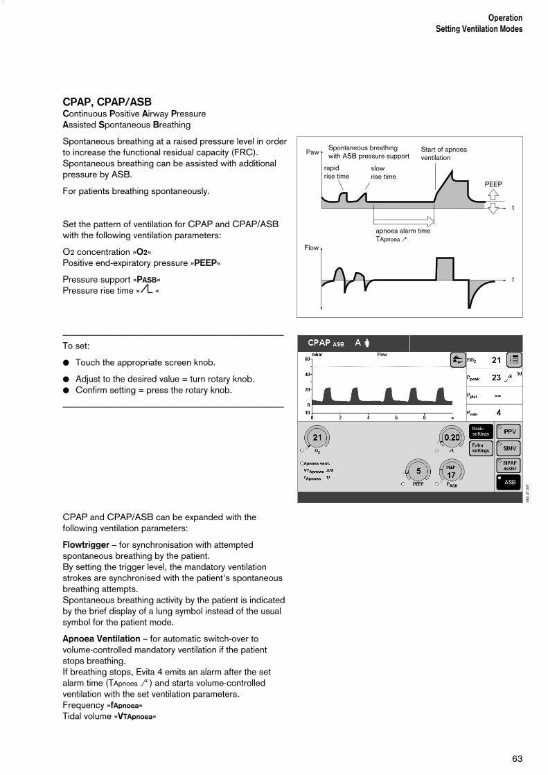
CPAP, CPAP/ASBContinuous Positive Airway PressureAssisted Spontaneous Breathing
Spontaneous breathing at a raised pressure level in orderto increase the functional residual capacity (FRC).Spontaneous breathing can be assisted with additionalpressure by ASB.
For patients breathing spontaneously.
Set the pattern of ventilation for CPAP and CPAP/ASBwith the following ventilation parameters:
O2 concentration »O2«Positive end-expiratory pressure »PEEP«
Pressure support »PASB«Pressure rise time » «
––––––––––––––––––––––––––––––––––––––––––––––––To set:
● Touch the appropriate screen knob.
● Adjust to the desired value = turn rotary knob.● Confirm setting = press the rotary knob.
––––––––––––––––––––––––––––––––––––––––––––––––
CPAP and CPAP/ASB can be expanded with thefollowing ventilation parameters:
Flowtrigger – for synchronisation with attemptedspontaneous breathing by the patient.By setting the trigger level, the mandatory ventilationstrokes are synchronised with the patient's spontaneousbreathing attempts.Spontaneous breathing activity by the patient is indicatedby the brief display of a lung symbol instead of the usualsymbol for the patient mode.
Apnoea Ventilation – for automatic switch-over tovolume-controlled mandatory ventilation if the patientstops breathing.If breathing stops, Evita 4 emits an alarm after the setalarm time (TApnoea > ) and starts volume-controlledventilation with the set ventilation parameters.Frequency »fApnoea«Tidal volume »VTApnoea«
63
OperationSetting Ventilation Modes
Paw
Flow
apnoea alarm timeTApnoea >
Start of apnoeaventilation
t
t
PEEP
rapidrise time
slowrise time
Spontaneous breathingwith ASB pressure support
083
37 2
07

––––––––––––––––––––––––––––––––––––––––––––––––To set (Example: Flowtrigger)
● Touch the »Extra settings« screen key.
● Touch the »Flow trigger« screen key.
● Set the value = touch the »FlowTrig« screen knob,and turn and press the rotary knob.
––––––––––––––––––––––––––––––––––––––––––––––––
OperationSetting Ventilation Modes
64
084
37 2
07

65
OperationSetting Ventilation Modes
MMV, MMV/ASBMandatory Minute Volume VentilationAssisted Spontaneous Breathing
The overall minute volume is preset to a mandatory level,which can be adjusted by means of the tidal volume VT
and frequency f.The patient can breathe spontaneously, therebycontributing a portion of the overall minute volume.The difference between the spontaneously breathedminute volume and the set minute volume is covered bythe mandatory ventilation strokes. Spontaneous breathingcan be assisted by ASB pressure support.
This mode is intended for patients being weaned off theventilator by progressively reducing the mandatoryproportion of the overall minute volume.
Set the pattern of ventilation for MMV and MMV/ASBwith the ventilation parameters:
Tidal volume »VT«Insp. flow »Flow«
Frequency »f«Inspiration time »Tinsp«
O2 concentration »O2«Positive end-expiratory pressure »PEEP«
Pressure support »PASB«Pressure rise time » «
––––––––––––––––––––––––––––––––––––––––––––––––To set:
● Touch the appropriate screen knob.
● Adjust to the desired value = turn rotary knob.● Confirm setting = press the rotary knob.
––––––––––––––––––––––––––––––––––––––––––––––––
MMV and MMV/ASB can be expanded with the followingventilation parameters:
Flowtrigger – for synchronisation with attemptedspontaneous breathing by the patient.By setting on the flow trigger level, the mandatory strokesare synchronised with the patient's spontaneousbreathing attempts.Spontaneous breathing activity by the patient is indicatedby the brief display of a lung symbol instead of the usualsymbol for the patient mode.
Paw
Flow
Tinsp
Pmax(configurable)
PEEP
shortrise time
longrise time
trigger phase
VT
Insp. Flow
t
t
1f
ASBpressure support
MV
sufficient spontaneous breathing
spontaneously breathed MV
set MV
mandatory MV
beginning spontaneous breathing
no spontaneous breathing
t
087
37 2
07
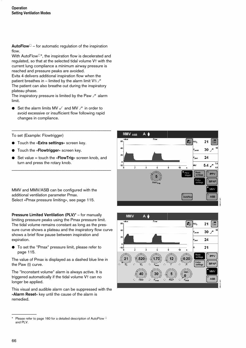
AutoFlow – for automatic regulation of the inspirationflow. With AutoFlow *, the inspiration flow is decelerated andregulated, so that at the selected tidal volume VT with thecurrent lung compliance a minimum airway pressure isreached and pressure peaks are avoided. Evita 4 delivers additional inspiration flow when thepatient breathes in – limited by the alarm limit VTi >The patient can also breathe out during the inspiratoryplateau phase. The inspiratory pressure is limited by the Paw > alarmlimit.
● Set the alarm limits MV < and MV > in order toavoid excessive or insufficient flow following rapidchanges in compliance.
––––––––––––––––––––––––––––––––––––––––––––––––To set (Example: Flowtrigger)
● Touch the »Extra settings« screen key.
● Touch the »Flowtrigger« screen key.
● Set value = touch the »FlowTrig« screen knob, andturn and press the rotary knob.
––––––––––––––––––––––––––––––––––––––––––––––––
MMV and MMV/ASB can be configured with theadditional ventilation parameter Pmax.Select »Pmax pressure limiting«, see page 115.
Pressure Limited Ventilation (PLV)* – for manuallylimiting pressure peaks using the Pmax pressure limit.The tidal volume remains constant as long as the pres-sure curve shows a plateau and the inspiratory flow curveshows a brief flow pause between inspiration andexpiration.
● To set the "Pmax" pressure limit, please refer to page 115.
The value of Pmax is displayed as a dashed blue line inthe Paw (t) curve.
The "Inconstant volume" alarm is always active. It istriggered automatically if the tidal volume VT can nolonger be applied.
This visual and audible alarm can be suppressed with the»Alarm Reset« key until the cause of the alarm isremedied.
––––––––––––* Please refer to page 160 for a detailed description of AutoFlow
and PLV.
66
OperationSetting Ventilation Modes
088
37 2
0708
9 37
207
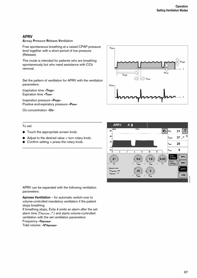
67
OperationSetting Ventilation Modes
APRVAirway Pressure Release Ventilation
Free spontaneous breathing at a raised CPAP pressurelevel together with a short period of low pressure(Release).
This mode is intended for patients who are breathingspontaneously but who need assistance with CO2
removal.
Set the pattern of ventilation for APRV with the ventilationparameters:
Inspiration time »Thigh«Expiration time »Tlow«
Inspiration pressure »Phigh«Positive end-expiratory pressure »Plow«
O2-concentration »O2«
––––––––––––––––––––––––––––––––––––––––––––––––To set:
● Touch the appropriate screen knob.
● Adjust to the desired value = turn rotary knob.● Confirm setting = press the rotary knob.
––––––––––––––––––––––––––––––––––––––––––––––––
APRV can be expanded with the following ventilationparameters:
Apnoea Ventilation – for automatic switch-over tovolume-controlled mandatory ventilation if the patientstops breathing.If breathing stops, Evita 4 emits an alarm after the setalarm time (TApnoea > ) and starts volume-controlledventilation with the set ventilation parameters:Frequency »fApnoea«Tidal volume: »VTApnoea«
Paw
Flow
Phigh
PlowThigh
Tlow
t
t
091
37 2
07

68
OperationSetting Ventilation Modes
––––––––––––––––––––––––––––––––––––––––––––––––To set (Example: Apnoea Ventilation)
● Touch the »Extra settings« screen key.
● Touch the »Apnoea vent.« screen key.
● Switch on the function = touch the »On« screen knoband press in the rotary knob.
● Set values = touch the corresponding screen knob,turn and press rotary knob.
––––––––––––––––––––––––––––––––––––––––––––––––
092
37 2
07
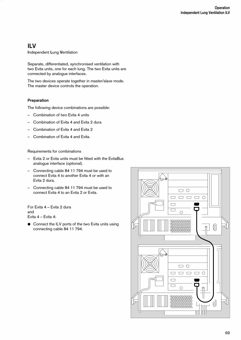
ILVIndependent Lung Ventilation
Separate, differentiated, synchronised ventilation withtwo Evita units, one for each lung. The two Evita units areconnected by analogue interfaces.
The two devices operate together in master/slave mode.The master device controls the operation.
Preparation
The following device combinations are possible:
– Combination of two Evita 4 units
– Combination of Evita 4 and Evita 2 dura
– Combination of Evita 4 and Evita 2
– Combination of Evita 4 and Evita.
Requirements for combinations
– Evita 2 or Evita units must be fitted with the EvitaBusanalogue interface (optional).
– Connecting cable 84 11 794 must be used toconnect Evita 4 to another Evita 4 or with an Evita 2 dura.
– Connecting cable 84 11 794 must be used toconnect Evita 4 to an Evita 2 or Evita.
For Evita 4 – Evita 2 dura andEvita 4 – Evita 4:
● Connect the ILV ports of the two Evita units usingconnecting cable 84 11 794.
69
OperationIndependent Lung Ventilation ILV

For Evita 4 – Evita 2andEvita 4 – Evita:
● Connect the ILV port of the Evita 4 to the analogueinterface of the other Evita unit using connecting cable 84 11 793.
OperationIndependent Lung Ventilation ILV
70
000

71
OperationIndependent Lung Ventilation ILV
Setting the Master and Slave device
To perform independent lung ventilation:
● Set up one device for ILV/Master mode
and
● the other device for ILV/Slave mode.
● Set the desired parameters – see page 19.
● Do not activate ILV mode until all the parameters for the ILV/Master and ILV/Slave are fully set.
Setting ILV/Master
Volume-controlled ventilation with fixed, mandatoryminute volume MV, set with tidal volume VT andfrequency f.
For independent lung ventilation of patients with nospontaneous breathing.
Set the ILV ventilation pattern with the parameters:
Tidal volume »VT«
Insp. flow »Flow«
Frequency »f«Inspiration time »Tinsp«
O2 concentration »O2«Positive end-expiratory pressure »PEEP«
––––––––––––––––––––––––––––––––––––––––––––––––To set:
● Touch the appropriate screen knob.
● Adjust the desired value = turn rotary knob● Confirm setting = press rotary knob.
––––––––––––––––––––––––––––––––––––––––––––––––
ILV/Master can be supplemented by the followingventilation parameters:
Flowtrigger (ILV/Master Assist) – for synchronisationwith attempted spontaneous breathing by the patient.By switching on the flow trigger and setting the triggerlevel, the mandatory strokes are synchronised with thepatient's spontaneous breathing attempts.Spontaneous breathing activity by the patient is indicatedby the brief display of a lung symbol instead of the usualsymbol for the patient mode.
Paw
Flow
Tinsp Te
Pplat
Insp.pause
Pmax(configu-rable)
PEEP
1f
Insp. flow
t
t
096
37 2
07

OperationIndependent Lung Ventilation ILV
72
Sigh – for prophylactic treatment of atelectasis.Atelectasis can be prevented by switching on the Sighfunction and setting the sigh in the form of an intermittentPEEP.When the Sigh function is activated, the end-expiratorypressure is increased by the set value of the intermittentPEEP for 2 ventilation strokes every 3 minutes.
ILV/Master can also be configured with the additionalventilation parameter Pmax.To set the »Pmax pressure limit«, please refer to page 115.
Pressure Limited Ventilation (PLV) – for manuallylimiting pressure peaks using the Pmax pressure limit.The tidal volume remains constant as long as thepressure curve shows a plateau and the flow curveshows a brief flow pause between inspiration andexpiration.
● To set the »Pmax pressure limit«, please refer to page 115.
The value of Pmax is displayed as a dashed blue line inthe Paw (t) curve.
The tidal volume is constantly monitored. If the tidalvolume VT can no longer be applied, the "Inconstantvolume" alarm is automatically triggered.This visual and audible alarm can be suppressed with the»Alarm Reset« key until the cause of the alarm isremedied.
097
37 2
07

73
OperationIndependent Lung Ventilation ILV
Setting ILV/Slave
Volume-controlled ventilation with fixed, mandatoryminute volume MV, set with the tidal volume VT andfrequency f of the ILV Master device and selectable Slavemode.
For independent lung ventilation of patients with nospontaneous breathing.
––––––––––––––––––––––––––––––––––––––––––––––––To set Slave mode:
● Touch the »Extra settings« screen key.
● Touch the »Slave Mode« screen key.
To select the desired slave mode (e.g. »Async.«):
● Touch the appropriate screen key and press the rotary knob.
––––––––––––––––––––––––––––––––––––––––––––––––
Paw
Flow
Tinsp Te
Pplat
Insp.pause
Pmax(configu-rable)
PEEP
1f
Insp. flow
t
t
099
37 2
07
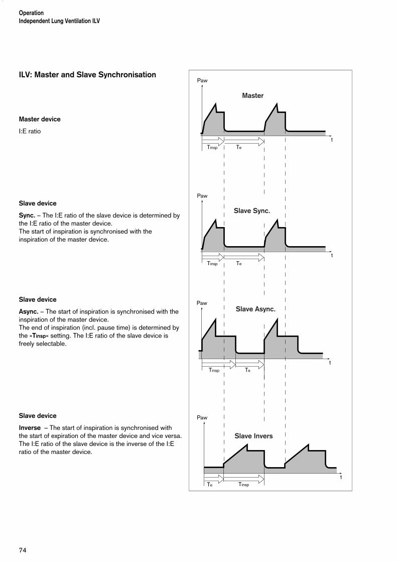
ILV: Master and Slave Synchronisation
Master device
I:E ratio
Slave device
Sync. – The I:E ratio of the slave device is determined bythe I:E ratio of the master device.The start of inspiration is synchronised with theinspiration of the master device.
Slave device
Async. – The start of inspiration is synchronised with theinspiration of the master device. The end of inspiration (incl. pause time) is determined bythe »Tinsp« setting. The I:E ratio of the slave device isfreely selectable.
Slave device
Inverse – The start of inspiration is synchronised withthe start of expiration of the master device and vice versa.The I:E ratio of the slave device is the inverse of the I:Eratio of the master device.
OperationIndependent Lung Ventilation ILV
74
Paw
Tinsp Te
t
Paw
Tinsp Te
t
Paw
Tinsp Te
t
Paw
TinspTe
t
Master
Slave Sync.
Slave Async.
Slave Invers
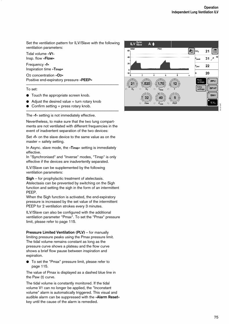
75
OperationIndependent Lung Ventilation ILV
Set the ventilation pattern for ILV/Slave with the followingventilation parameters:
Tidal volume »VT«
Insp. flow »Flow«
Frequency »f«Inspiration time »Tinsp«
O2 concentration »O2«Positive end-expiratory pressure »PEEP«––––––––––––––––––––––––––––––––––––––––––––––––To set:
● Touch the appropriate screen knob.
● Adjust the desired value = turn rotary knob● Confirm setting = press rotary knob.––––––––––––––––––––––––––––––––––––––––––––––––The »f« setting is not immediately effective.
Nevertheless, to make sure that the two lung compart-ments are not ventilated with different frequencies in theevent of inadvertent separation of the two devices:
Set »f« on the slave device to the same value as on themaster = safety setting.
In Async. slave mode, the »Tinsp« setting is immediatelyeffective.In "Synchronised" and "Inverse" modes, "Tinsp" is onlyeffective if the devices are inadvertently separated.
ILV/Slave can be supplemented by the followingventilation parameters:
Sigh – for prophylactic treatment of atelectasis.Atelectasis can be prevented by switching on the Sighfunction and setting the sigh in the form of an intermittentPEEP.When the Sigh function is activated, the end-expiratorypressure is increased by the set value of the intermittentPEEP for 2 ventilation strokes every 3 minutes.
ILV/Slave can also be configured with the additionalventilation parameter "Pmax". To set the "Pmax" pressurelimit, please refer to page 115.
Pressure Limited Ventilation (PLV) – for manuallylimiting pressure peaks using the Pmax pressure limit.The tidal volume remains constant as long as thepressure curve shows a plateau and the flow curveshows a brief flow pause between inspiration andexpiration.
● To set the "Pmax" pressure limit, please refer to page 115.
The value of Pmax is displayed as a dashed blue line inthe Paw (t) curve.
The tidal volume is constantly monitored. If the tidalvolume VT can no longer be applied, the "Inconstantvolume" alarm is automatically triggered. This visual andaudible alarm can be suppressed with the »Alarm Reset«key until the cause of the alarm is remedied.
101
37 2
07

Apnoea VentilationFor automatic switch-over to volume-controlledmandatory ventilation if the patient stops breathing. It can be switched on in the ventilation modes SIMV,BIPAP, CPAP, APRV.Evita 4 emits an apnoea alarm if during the set alarmperiod »TApnoea« no expiration flow is measured orinsufficient inspiratory gas is delivered.If breathing stops, Evita 4 emits an alarm after the setalarm time (TApnoea > ) and starts volume-controlledventilation with the set ventilation parameters:Frequency »fApnoea«Tidal volume: »VTApnoea«
The ventilation parameters »O2« and »PEEP« correspondto the settings effective at the time.The inspiration time for apnoea ventilation is determinedfrom the set apnoea frequency »fApnoea« and a fixed I:E ratio of 1:2.
As in SIMV, the patient can breathe spontaneously duringapnoea ventilation, and the mandatory ventilation strokeswill be synchronised with the patient's spontaneousbreathing. The apnoea ventilation frequency remainsconstant.
––––––––––––––––––––––––––––––––––––––––––––––––To set:
● Touch the »Extra settings« screen key.
● Touch the »Apnoea vent.« screen key.
● Switch on the function = touch the screen knobmarked »On«, and press the rotary knob.
● Set values = touch the appropriate screen knob, and then turn and press the rotary control.
––––––––––––––––––––––––––––––––––––––––––––––––
Status and settings for apnoea ventilation are displayedby Evita 4 on the "Settings" screen.
To terminate Apnoea Ventilation:
● Press the »Alarm Reset« key: the device will continueoperating in its previous ventilation mode
or
● select another ventilation mode.
For configuring the status of apnoea ventilation whenswitching on the device, see page 117.
76
OperationApnoea Ventilation
Paw
Flow
apnoea alarm timeTApnoea >
Start of apnoeaventilation
t
t
PEEP
Spontaneous breathingwith ASB pressure support
1fApnoea
103
37 2
07
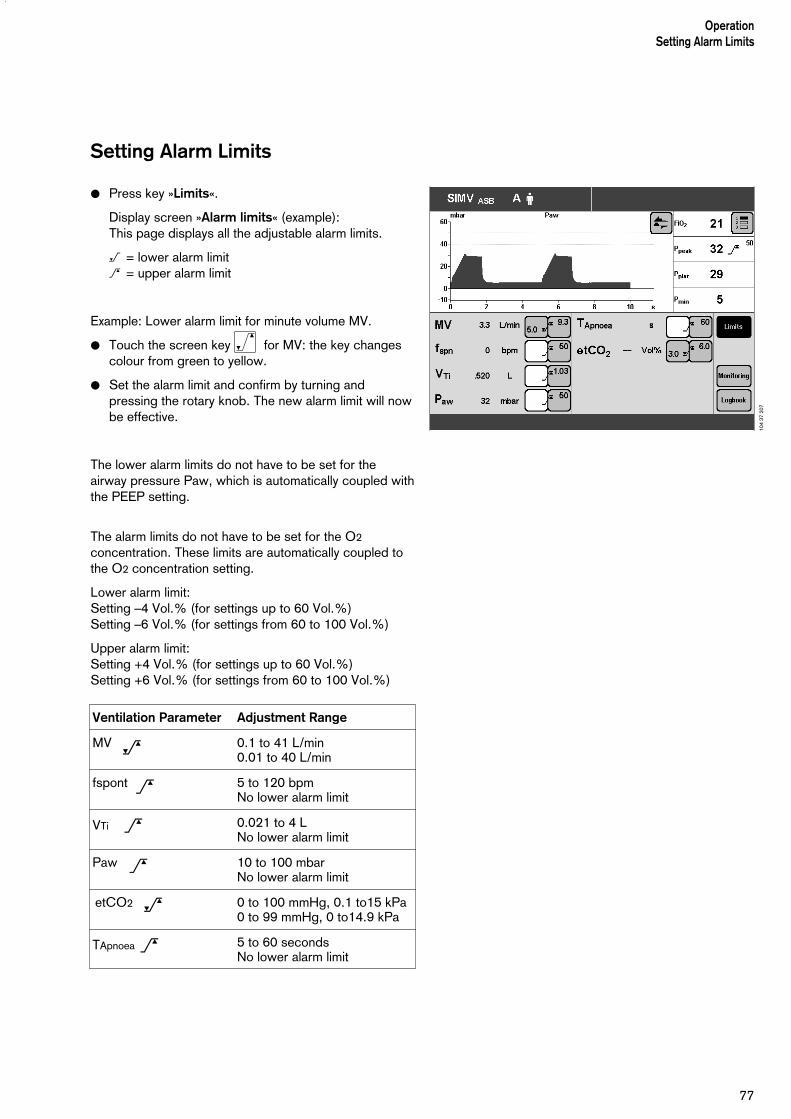
77
OperationSetting Alarm Limits
Setting Alarm Limits
● Press key »Limits«.
Display screen »Alarm limits« (example):This page displays all the adjustable alarm limits.
< = lower alarm limit> = upper alarm limit
Example: Lower alarm limit for minute volume MV.
● Touch the screen key for MV: the key changescolour from green to yellow.
● Set the alarm limit and confirm by turning andpressing the rotary knob. The new alarm limit will nowbe effective.
The lower alarm limits do not have to be set for theairway pressure Paw, which is automatically coupled withthe PEEP setting.
The alarm limits do not have to be set for the O2
concentration. These limits are automatically coupled tothe O2 concentration setting.
Lower alarm limit:Setting –4 Vol.% (for settings up to 60 Vol.%)Setting –6 Vol.% (for settings from 60 to 100 Vol.%)
Upper alarm limit:Setting +4 Vol.% (for settings up to 60 Vol.%)Setting +6 Vol.% (for settings from 60 to 100 Vol.%)
Ventilation Parameter Adjustment Range
MV 0.1 to 41 L/min0.01 to 40 L/min
fspont 5 to 120 bpmNo lower alarm limit
VTi 0.021 to 4 LNo lower alarm limit
Paw 10 to 100 mbarNo lower alarm limit
etCO2 0 to 100 mmHg, 0.1 to15 kPa0 to 99 mmHg, 0 to14.9 kPa
TApnoea 5 to 60 secondsNo lower alarm limit
_
_
>
>
>
>
104
37 2
07

In the Event of an Alarm
1 the red lamp or yellow lamp flashes.
2 the alarm message is displayed in the right-handcorner of the top line of the screen.
Evita 4 assesses the alarm message with correspondingpriority, marks the text with exclamation marks anddifferent coloured backgrounds and generates thevarious alarm tone sequences.
Warning = top priority message
The red lamp flashes.The alarm messages are marked with three exclamationmarks.
Example: Apnoea !!!
Warning messages are displayed against a redbackground.Evita 4 generates a 5-tone sequence that is soundedtwice and is repeated every 7 seconds.
Caution = medium priority message
The yellow lamp flashes.Warning messages are marked with two exclamationmarks.
Example: O2 supply pressure high !!
Caution messages are displayed against a yellowbackground.Evita 4 generates a 3-tone sequence that is repeatedevery 20 seconds.
Advisory = low priority message
The yellow lamp remains constantly lit.Note messages are marked with one exclamation mark.
Example: Malfunction fan !
Advisory messages are displayed against a yellowbackground.Evita 4 generates a 2-tone sequence that sounds onlyonce.
If the loudspeaker for audible alarms fails on account of adefect, an auxiliary signal will sound continuously.This continuous tone also serves as power failure alarm,see page 36, if power is interrupted while the ventilator isin use.
To remedy the faults, please refer to the "Troubleshoo-ting" section starting on page 127.
OperationIn the Event of an Alarm
78
D Evita 4
2 1

Once the fault has been remedied, the alarm tone isswitched off. Caution and advisory messages disappearautomatically.
Warning messages (!!!) are displayed in the colour of thestatus line and must be acknowledged:
1 Press »Alarm Reset« key.
The message is erased from the screen. However, it isstored in Evita 4 and can be displayed with the logbookfunction in the »Measured Values« screen page, seepage 85.
Cancel alarm tone
for max. 2 minutes:
2 Press the »g « key with the lit yellow indicator LED.The acoustic alarm will be cancelled for 2 minutes. Ifthe fault that triggered the alarm is still not remedied,the acoustic alarm starts up again. If you wish toreactivate the acoustic alarm temporarily:
2 Press the »g « key (with the yellow LED nowswitched off) again.
Acknowledge:
3 Press »Alarm Reset« to acknowledge the alarms thatcan be suppressed with "Alarm Reset":please refer to "Troubleshooting" on page 127.
Information J– For help in operating the system – with setting
instructions.
– For help in troubleshooting.
4 Press the » « key: information is displayed in thebottom line of the screen.
To erase the message:
4 Press the » « key again.
79
OperationIn the Event of an Alarm
D Evita 4
1
D Evita 4
2
3
D Evita 4
4

Displaying Curves and MeasuredValues
In the standard page
● Press »? « key.
»Standard page« display:In the right-hand field: 4 measured valuesIn the left-hand field: 2 curves
To select one of the three measured value combinations:
● Touch screen key » « repeatedly.
Select three other curves:
● Touch screen key » « , and touch the relevant screen key.
Measured values and curves can be selected, seeconfiguration, page 109 or 111 onwards.
In all other screen pagese.g. »Settings page«
● Press »Settings«.
»Settings« display:Right-hand field: 4 measured values (as in the standard page)Left-hand field: 1 curve.
To select one of the three measured value combinations:
● Touch the screen key » « repeatedly.
To select three other curves:
● Touch the screen key » « , and touch the relevantscreen key.
Measured values and curves can be selected, seeconfiguration, page 109 or 111 onwards.
OperationDisplaying Curves and Measured Values
80
123
123
109
37 2
0711
0 37
207

Displaying measured values
● Press the »Meas. values« key.
»Table 1« display
Evita 4 displays the measured values with the units ofmeasure in the form of a table. The measured values aresummarised in Table 1 and Table 2.
»Table 2« display The following are displayed optionally:
VTASB – inspiratory breathing volume during an ASBstroke
RSB Rapid Shallow Breathing1)
NIF Negative Inspiratory Force2)
_____________
1) For a detailed description of RSB, refer to the Annex, page 1752) For a detailed description of NIF, refer to the Annex, page 175
For information on using NIF, refer to "Manual expiration", page 87
81
OperationDisplaying Curves and Measured Values
111
37 2
0711
2 37
207
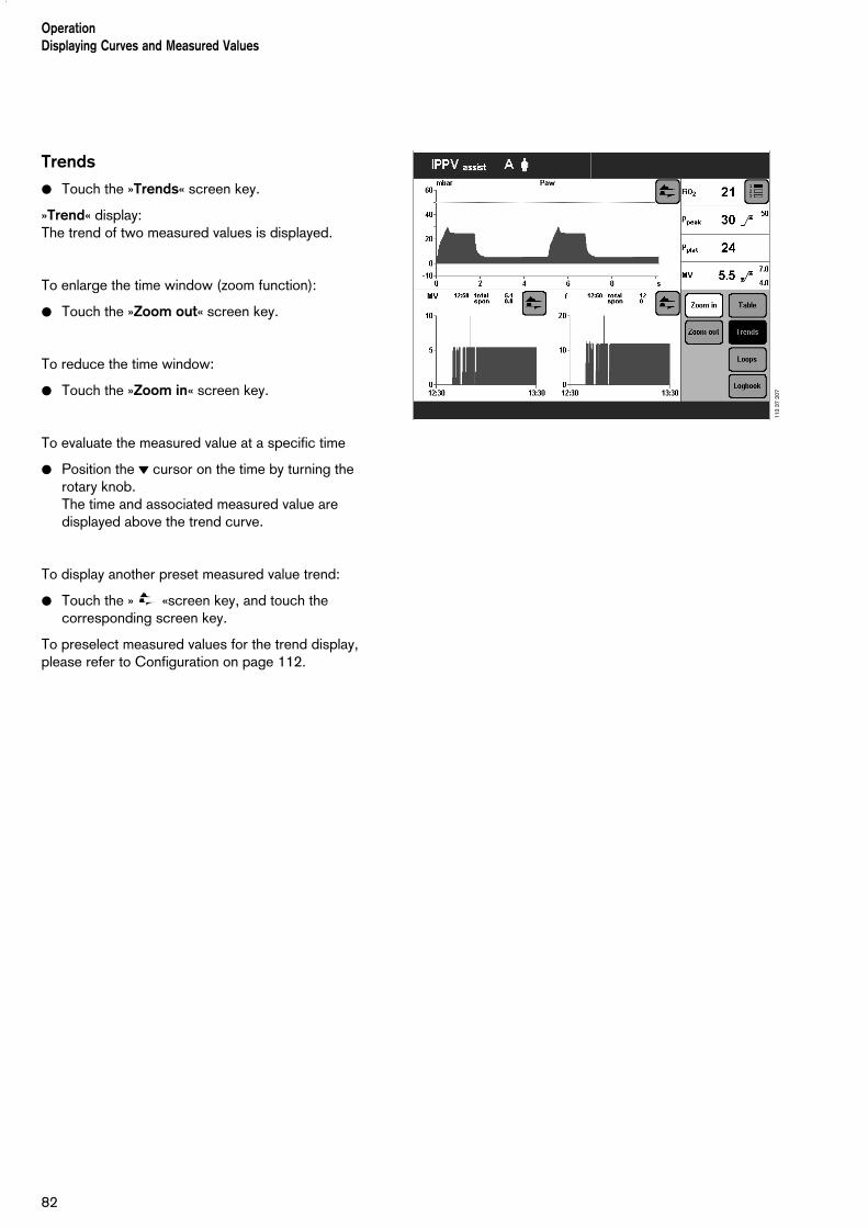
Trends
● Touch the »Trends« screen key.
»Trend« display:The trend of two measured values is displayed.
To enlarge the time window (zoom function):
● Touch the »Zoom out« screen key.
To reduce the time window:
● Touch the »Zoom in« screen key.
To evaluate the measured value at a specific time
● Position the l cursor on the time by turning the rotary knob. The time and associated measured value aredisplayed above the trend curve.
To display another preset measured value trend:
● Touch the » «screen key, and touch the corresponding screen key.
To preselect measured values for the trend display,please refer to Configuration on page 112.
82
OperationDisplaying Curves and Measured Values
113
37 2
07

Loops
● Touch the »Loops« screen key.
»Loop« display:Two pairs of measured values plotted against each otherappear in the ventilation cycle as a loop, e.g. the Paw-Vloop and the V-Flow loop.
To select another preset pair of measured values as aloop:
● Touch the » « screen key in the Loop display.
Reference curve displays
To display the recorded loop of a particular breathingcycle as a permanent on-screen reference for the currentloop:
Date and time of the reference are displayed on thescreen.
● Press the »Reference« screen key.
The date and time of the reference curve appear belowthe »Reference« screen key (available as upgrade).
Single stroke displays
To display an individual breathing cycle in ventilationmodes that have both mechanical and spontaneouscomponents, e.g. SIMV:
● Press the »Single stroke« screen key.
If no single stroke is selected for display, the entirebreathing activity from mandatory stroke to mandatorystroke will be recorded.
Zoom loops (available as upgrade)
The right-hand loop can be zoomed to fill the full screenincluding the graphic areas at the top and bottom.
● Touch the »Zoom« screen key.Display »Loops«.The right-hand loop is zoomed and the other loopdisappears with the time-based curves.
The loop to be displayed can be selected even whenzoomed.
The functions »Reference« and »Single stroke« areretained.
83
OperationDisplaying Curves and Measured Values
114
37 2
0711
5 37
207

Return to the normal loop display:
● Touch the »Zoom« screen key.
The time-based curve automatically reappears when theloop page is exited.
Display loops in the upper graphic area (available asupgrade)
● Touch the » « screen key.
● Touch the »Loops« screen key.
The time-based curves are replaced by the two loops inthe upper graphic area.
The Freeze function can also be used with loops in theupper graphic area.Loops in the upper graphic area cannot be configuredwhen
– the »Loops« menu is open,– the »Configuration« key has been selected.
To restore the time-based curves in the upper graphicarea:
● Touch the right-hand » « screen key.
● Touch the »Curves« screen key.
OperationDisplaying Curves and Measured Values
84
116
37 2
0711
7 37
207
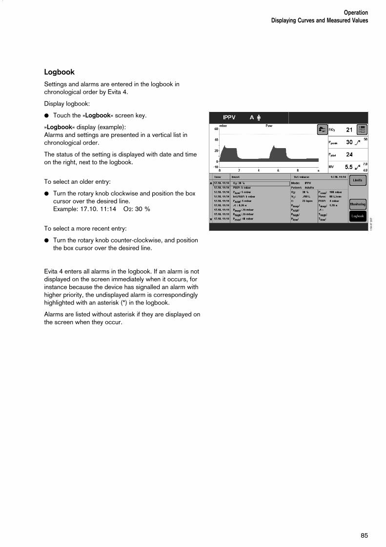
Logbook
Settings and alarms are entered in the logbook inchronological order by Evita 4.
Display logbook:
● Touch the »Logbook« screen key.
»Logbook« display (example):Alarms and settings are presented in a vertical list inchronological order.
The status of the setting is displayed with date and timeon the right, next to the logbook.
To select an older entry:
● Turn the rotary knob clockwise and position the boxcursor over the desired line. Example: 17.10. 11:14 O2: 30 %
To select a more recent entry:
● Turn the rotary knob counter-clockwise, and positionthe box cursor over the desired line.
Evita 4 enters all alarms in the logbook. If an alarm is notdisplayed on the screen immediately when it occurs, forinstance because the device has signalled an alarm withhigher priority, the undisplayed alarm is correspondinglyhighlighted with an asterisk (*) in the logbook.
Alarms are listed without asterisk if they are displayed onthe screen when they occur.
85
OperationDisplaying Curves and Measured Values
118
37 2
07

Screen freeze
To "freeze" the curves and loops (freezing loops isoptional)
1 Press »Stop« key.
To display the pair of measured values, a point on thecurve or loop:
2 Position the cursor on the relevant point by turning the rotary knob.The corresponding pair of measured values isdisplayed above and beside the curve.
The Reference key remains disabled as long as theFreeze function is active.
To display new curves / loops again:
1 Press »Stop« key again.
Screen freeze mode is automatically terminated 3 minutes after the rotary control was last turned.
OperationDisplaying Curves and Measured Values
86
D Evita 4
1
2

Special Functions
Manual inspiration
This function may be used in all modes except CPAPwithout ASB pressure support.Depending on the start time, an automatic ventilationstroke is prolonged for a maximum of 15 seconds.Or:Between two automatic ventilation strokes, a ventilationstroke can be manually started and held for max. 15 seconds.
The pattern of the manually started ventilation strokecorresponds to the ventilation pattern of the currentlyactive automatic ventilation mode.
In CPAP/ASB:a pressure-assisted ventilation stroke (defined by thePASB setting) is triggered.
1 Press »Insp. hold« key and hold it down for as longas inspiration is required.
Either a just activated automatic ventilation stroke will beprolonged or a new ventilation stroke will be started andappropriately prolonged – max. 15 seconds.
Exspiration Hold
This function may be used in all ventilation modes.For determining the measured NIF1) value for weaning
2 Hold down the »Exp. hold« key.
The expiration phase remains effective as long as the keyis held down and Evita 4 determines the measured NIFvalue. If the key is not released, the device automaticallyterminates the expiration phase after 15 seconds.
_____________
1) Display NIF, see page 81.For a detailed description of NIF, refer to the Annex, page 175.
87
OperationSpecial Functions
D Evita 4
12

Medicament nebulisation
During adult ventilation
Applicable in every ventilation mode.Evita 4 applies the medicament aerosol in synchronisa-tion with the inspiratory flow phase and maintains theminute volume constant.
The medicament nebuliser is supplied by the ventilatorwith medical air, oxygen or a mixture of medical air andoxygen according to the set O2 concentration. Deviationsin O2 concentration are therefore kept to a minimum.
In extreme cases (with a minimum inspiration flow of 15 L/min), the deviations can be up to ± 4 % by volume*.To avoid greater deviations, medicament nebulisation isautomatically switched off with inspiration flows below 15 L/min.
During paediatric ventilation
Medicament nebulisation is possible in the pressure-controlled paediatric ventilation modes.
In volume-controlled ventilation modes, medicamentnebulisation is only possible with AutoFlow .
Unlike in adult ventilation, the medicament nebulisernebulises continuously in paediatric ventilation, but theaerosol generated during expiration does not reach thelungs.
Depending on the set O2 concentration, the medicamentnebuliser is supplied by the ventilator with medical air,oxygen or a mixture of medical air and oxygen. Deviationsin O2 concentration are therefore kept to a minimum.
We recommend that you do not use the medicamentnebuliser at breathing rates of less than 12 bpm.
For breathing rates above 12 bpm, please refer to thegraph on page 177.
The maximum possible deviations in O2 concentration are ±4 % by volume.
For breathing rates of less than 12 bpm, thedeviations in O2 concentration may be much greater.
These deviations cannot be detected by the device'sinternal O2 concentration monitor.
_____________
* For a detailed description of the inspiratory O2 concentration during medicament nebulisation, please refer to the Appendix, page 177.
88
OperationSpecial FunctionsMedicament nebulisation

The medicament nebuliser is automatically switched offafter 30 minutes.After administration of the aerosol, the flow sensor isautomatically cleaned and calibrated in order to preventmalfunctions in flow measurement.
Only use medicament nebuliser 84 12 935 (white central body).Prepare the medicament nebuliser in accordance with itsInstructions for Use.
If other pneumatic medicament nebulisers are used,there may be major deviations in tidal volume andinspiratory O2 concentration.
For use during adult ventilation
1 Connect the nebuliser to the inspiratory side(temperature sensor side) of the Y-piece.
2 Connect the inspiration hose to the medicamentnebuliser.
● Place the medicament nebuliser in the verticalposition.
● Using clamps, route the nebuliser hose back to theventilator along the expiratory hose.
For use during paediatric ventilation
3 Insert the catheter connector (ISO cone Ø15 / Ø11)in the inlet of the medicament nebuliser.
4 Insert the adapter (ISO cone Ø22 / Ø11) in the outlet.
5 Fit the corrugated hose (0.13 m long) to the outletadapter.
6 Remove the corrugated hose of the hose set from theinspiratory adapter of the Y-piece and connect it tothe inlet adapter of the medicament nebuliser.
7 Connect the free end of the corrugated hose at theoutlet of the medicament nebuliser to the inspiratoryadapter of the Y-piece.
89
1
2
345
67
OperationSpecial Functions
Medicament nebulisation
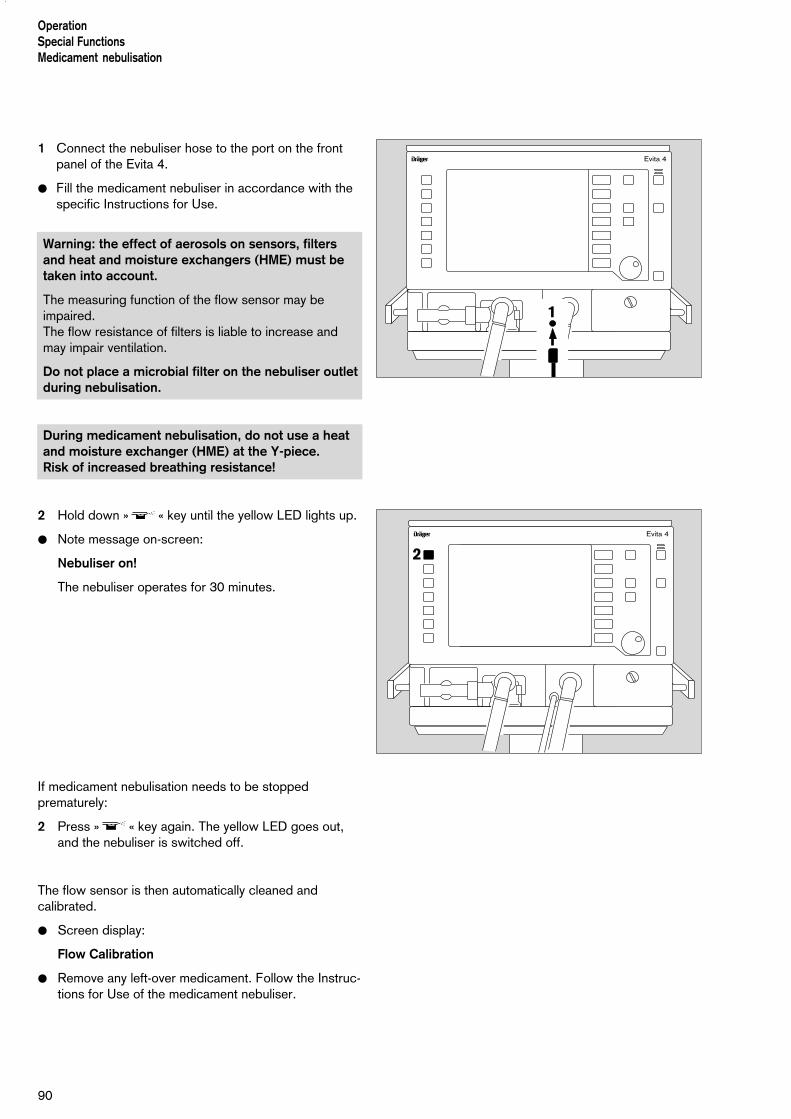
1 Connect the nebuliser hose to the port on the front panel of the Evita 4.
● Fill the medicament nebuliser in accordance with the specific Instructions for Use.
Warning: the effect of aerosols on sensors, filters and heat and moisture exchangers (HME) must betaken into account.
The measuring function of the flow sensor may beimpaired.The flow resistance of filters is liable to increase andmay impair ventilation.
Do not place a microbial filter on the nebuliser outletduring nebulisation.
During medicament nebulisation, do not use a heatand moisture exchanger (HME) at the Y-piece. Risk of increased breathing resistance!
2 Hold down » « key until the yellow LED lights up.
● Note message on-screen:
Nebuliser on!
The nebuliser operates for 30 minutes.
If medicament nebulisation needs to be stoppedprematurely:
2 Press » « key again. The yellow LED goes out,and the nebuliser is switched off.
The flow sensor is then automatically cleaned andcalibrated.
● Screen display:
Flow Calibration
● Remove any left-over medicament. Follow the Instruc-tions for Use of the medicament nebuliser.
90
OperationSpecial FunctionsMedicament nebulisation
D Evita 4
1
D Evita 4
2

D Evita 4
1
91
OperationSpecial Functions
Oxygen enrichment for bronchial suction
Oxygen enrichment for bronchial suction
To avoid any risk of hypoxia during bronchial suction,Evita 4 offers a program for oxygen enrichment during the removal of secretions.
After the program is started, Evita 4 ventilates the patientin the selected ventilation mode for an initial oxygenenrichment phase of 180 seconds. In adult mode, theventilator supplies 100 % oxygen by volume, and inpaediatric mode it delivers the set O2 concentration plus 25 % (for example: setting = 60 % by vol.; administered = 75 % by vol.)
When the ventilator is disconnected for suction, Evita 4interrupts ventilation. During the suction phase, theaudible alarms are suppressed so that the suction routineis not disturbed.
After suction and automatically recognised reconnection,Evita 4 delivers an increased O2 concentration for thefinal oxygen enrichment phase of 120 seconds. In adultmode, the O2 concentration is 100 % by volume. Inpaediatric mode, the enriched concentration is 25 %higher than the set concentration.During suction and for 2 minutes afterwards, the loweralarm limit for the minute volume is switched off.
Other alarms are switched off during suction and for 15 seconds afterwards.
Oxygen enrichment is only possible with a fullyfunctioning flow sensor and if flow monitoring isswitched on.
Before suction
1 Hold down the »O2 suction« key until the yellowLED comes on.Evita 4 ventilates the patient in the set ventilationmode with increased O2 concentration: 100 % O2 byvolume in adult mode, and 25 % higher O2 con-centration than the set value in paediatric mode.If PEEP is not set to more than 4 mbar, PEEP will beapplied automatically at 4 mbar. This PEEP will enableEvita 4 to detect any subsequent disconnection.The other ventilation parameters remain unaffected.
● Display in the help line at the bottom edge of thescreen:
O2 enrichment 180 s
The remaining time is counted down continuously. This initial oxygen enrichment lasts for a maximum of 180 seconds. During this time, Evita 4 waits for a dis-connection for suction.If there is no disconnection after expiry of the 180 seconds, the oxygen enrichment program isterminated.

After disconnection for suction
Evita 4 delivers a minimal flow for the duration of suctionin order to detect automatically the end of thedisconnection phase. In the help line at the bottom edgeof the screen, the time available for suction is displayedcontinuously in seconds (example):
Execute suction and reconnect 120 s
If suction is ended and the system is reconnected withinthe displayed time, Evita 4 terminates the disconnectionphase.
Automatic interruption of oxygen enrichment
If there is still no reconnection after 120 seconds, theoxygen enrichment program is interrupted. All alarms areimmediately reactivated. Evita 4 continues ventilating inthe set ventilation mode.
After reconnection
After reconnection, Evita 4 continues ventilating in the setventilation mode, except that for 120 seconds theincreased oxygen concentration of 100 % by volume foradults and 25 % above the set concentration forpaediatric ventilation will continue to be delivered for final(post-suction) oxygen enrichment.
● Display in the help line at the bottom of the screen:
Final O2 enrichment 120 s
The remaining time is counted down continuously.
If you need to interrupt oxygen enrichment:
1 Press the »O2 suction« key again.
92
OperationSpecial FunctionsOxygen enrichment for bronchial suction
D Evita 4
1

Special measuring procedure: Intrinsic PEEP
Intrinsic PEEP* is the actual end-expiratory pressure inthe lung.
Due to the dynamics of lung mechanics (resistance,compliance and closing volume) and the ventilationsetting parameters, the intrinsic PEEP differs from thePEEP in the upper airways.
The Intrinsic PEEP measuring procedure also measuresthe trapped volume resulting from the different PEEPvalues, i.e. the amount of air trapped in the lungs and nottaking part in the gas exchange process.
This special procedure can be performed in all ventilationmodes.
Activity by the patient during this procedure candistort the measured values.
Select the Intrinsic PEEP special procedure:
● Press the »Special proc.« key and touch the »PEEPi«screen key.
Display (example):The measured values and the time of the last measure-ment are displayed on the screen.
To start the Intrinsic PEEP measurement:
● Touch the »Start« screen key.
The Intrinsic PEEP measurement runs automatically.
At the end of the procedure, the new measured valuesPEEPi and Vtrap are displayed.
The displayed curve is automatically stopped.
To evaluate the measured value at a particular time:
● Position the l cursor on the time by turning the dial-knob.The associated measured value is displayed above thecurve.
_____________
* For a detailed description of Intrinsic PEEP, refer to the Annex, page 176.
93
OperationSpecial Functions
128
37 2
07

OperationSpecial Functions
94
Special procedure: Occlusion pressure P 0.1
The occlusion pressure P 0.1 characterises the negativepressure during a short occlusion (0.1 s) at the start ofspontaneous inspiration. It is a direct measure of the neuro-muscular breathingdrive.For patients with healthy lungs and regular breathing, apressure drop of –3 to –4 mbar = P 0.1.High values represent a high breathing drive which canonly be maintained for a short time.Values greater than –6 mbar for a patient with chronicobstructive pulmonary disease indicate impendingexhaustion (respiratory muscle fatigue).
This special measuring procedure can be used in allventilation modes in order to check the breathing drive ofa spontaneously breathing patient or to assess theamount of spontaneous breathing during controlledventilation.
To select the P 0.1 occlusion pressure measuringprocedure:
● Press the »Special proc.« key and touch screen key »P 0.1«.
Display (example):The measured value and time of the last measurement isdisplayed on the screen.
To start the P 0.1 occlusion pressure measuringprocedure:
● Touch the »Start« screen key.
The P 0.1 special procedure runs automatically.
At the end of the procedure, the displayed curve isautomatically stopped.
To evaluate the measured value at a particular time:
● Position the l cursor on the time by turning the dial-knob.The relevant measured value is displayed above thecurve.
Evita 4 displays the P 0.1 value as a negative pressure without the minus sign.
129
37 2
07

95
OperationSpecial Functions
Switching off the monitor functions
e.g. if a spent sensor cannot be replaced.
Immediately make sure there is an adequate externalmonitor backup!
Example: Switching off Flow Monitoring.
● Press »Alarm limits« key.
Display (example):
● Touch »Monitoring« screen key.
Display (example):
For the example of switching off flow monitoring:
● Touch the »Flow off« screen key.The key changes colour from green to yellow.
To confirm that you wish to switch off Flow Monitoring:
● Press rotary knob. Flow Monitoring is switched off,and the corresponding measured values disappear.The alarm function is switched off.
After replacing the sensor:
● Switch the monitor function back on.
130
37 2
0713
1 37
207

96
D Evita 4
2
1
Selecting Standby Mode
No ventilation takes place in standby mode!
Uses of Standby:
– to perform the device check
– to maintain Evita 4 ready for operation while thepatient is absent.
– to change patient mode.
1 Hold down the »O« key for about 3 seconds.
An alarm tone sounds after switching on standby.
To switch off the standby alarm tone:
2 Press »Alarm Reset« key.
The standby alarm tone cannot be cancelled with the »g« key.
Display (example):
If the patient mode or ideal body weight should bechanged during Standby, Evita 4 will determine new startvalues for ventilation, see page 50.
Terminating standby mode
– to continue ventilation.
1 Press »O« key.The LED goes out, and the current ventilationparameters are again effective.
OperationSelecting Standby Mode
133
37 2
07
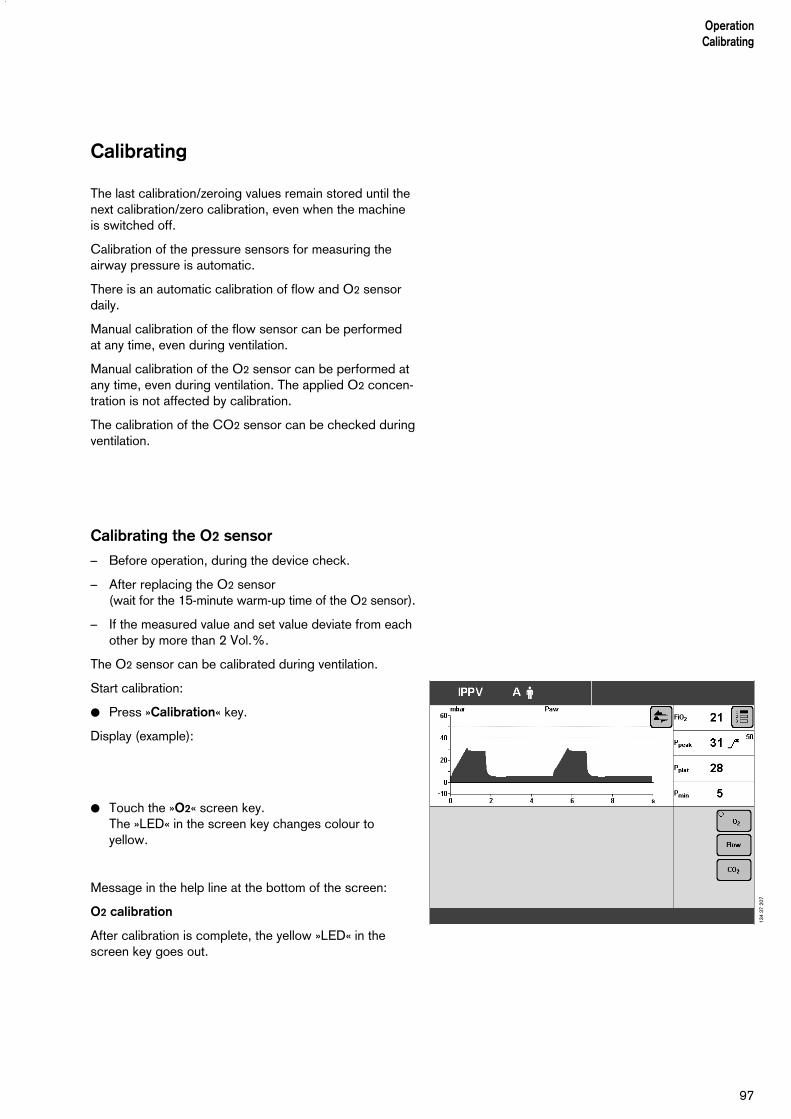
97
OperationCalibrating
Calibrating
The last calibration/zeroing values remain stored until thenext calibration/zero calibration, even when the machineis switched off.
Calibration of the pressure sensors for measuring theairway pressure is automatic.
There is an automatic calibration of flow and O2 sensordaily.
Manual calibration of the flow sensor can be performedat any time, even during ventilation.
Manual calibration of the O2 sensor can be performed atany time, even during ventilation. The applied O2 concen-tration is not affected by calibration.
The calibration of the CO2 sensor can be checked duringventilation.
Calibrating the O2 sensor
– Before operation, during the device check.
– After replacing the O2 sensor(wait for the 15-minute warm-up time of the O2 sensor).
– If the measured value and set value deviate from eachother by more than 2 Vol.%.
The O2 sensor can be calibrated during ventilation.
Start calibration:
● Press »Calibration« key.
Display (example):
● Touch the »O2« screen key.The »LED« in the screen key changes colour toyellow.
Message in the help line at the bottom of the screen:
O2 calibration
After calibration is complete, the yellow »LED« in thescreen key goes out.
134
37 2
07
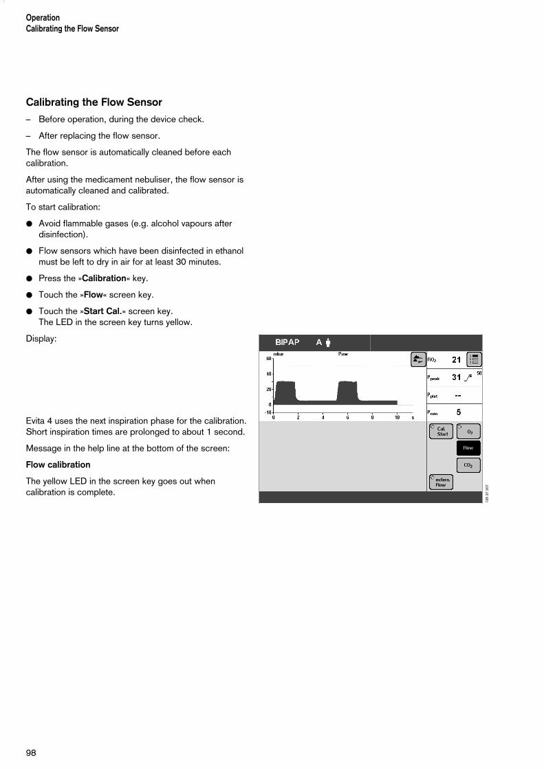
Calibrating the Flow Sensor
– Before operation, during the device check.
– After replacing the flow sensor.
The flow sensor is automatically cleaned before eachcalibration.
After using the medicament nebuliser, the flow sensor isautomatically cleaned and calibrated.
To start calibration:
● Avoid flammable gases (e.g. alcohol vapours afterdisinfection).
● Flow sensors which have been disinfected in ethanolmust be left to dry in air for at least 30 minutes.
● Press the »Calibration« key.
● Touch the »Flow« screen key.
● Touch the »Start Cal.« screen key.The LED in the screen key turns yellow.
Display:
Evita 4 uses the next inspiration phase for the calibration.Short inspiration times are prolonged to about 1 second.
Message in the help line at the bottom of the screen:
Flow calibration
The yellow LED in the screen key goes out whencalibration is complete.
OperationCalibrating the Flow Sensor
98
135
37 2
07
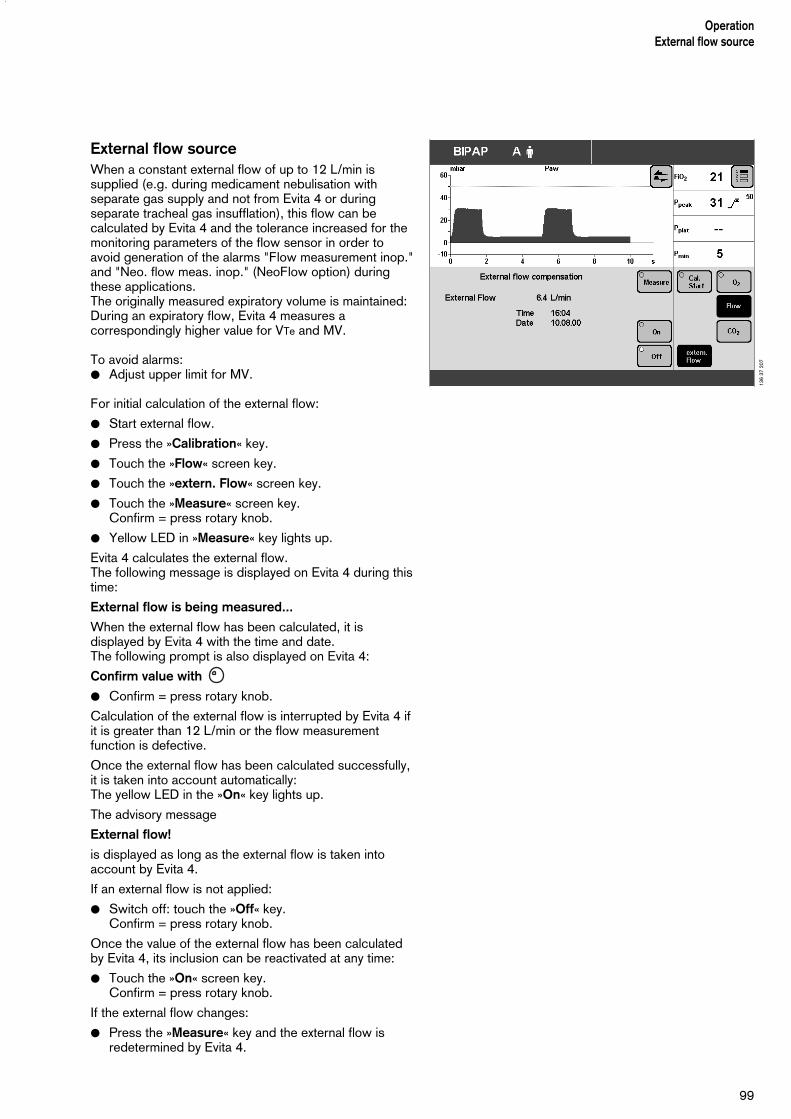
External flow sourceWhen a constant external flow of up to 12 L/min issupplied (e.g. during medicament nebulisation withseparate gas supply and not from Evita 4 or duringseparate tracheal gas insufflation), this flow can becalculated by Evita 4 and the tolerance increased for themonitoring parameters of the flow sensor in order toavoid generation of the alarms "Flow measurement inop."and "Neo. flow meas. inop." (NeoFlow option) duringthese applications.The originally measured expiratory volume is maintained:During an expiratory flow, Evita 4 measures acorrespondingly higher value for VTe and MV.
To avoid alarms:● Adjust upper limit for MV.
For initial calculation of the external flow:
● Start external flow.
● Press the »Calibration« key.
● Touch the »Flow« screen key.
● Touch the »extern. Flow« screen key.
● Touch the »Measure« screen key.Confirm = press rotary knob.
● Yellow LED in »Measure« key lights up.
Evita 4 calculates the external flow.The following message is displayed on Evita 4 during thistime:
External flow is being measured...
When the external flow has been calculated, it isdisplayed by Evita 4 with the time and date.The following prompt is also displayed on Evita 4:
Confirm value with
● Confirm = press rotary knob.
Calculation of the external flow is interrupted by Evita 4 ifit is greater than 12 L/min or the flow measurementfunction is defective.
Once the external flow has been calculated successfully,it is taken into account automatically:The yellow LED in the »On« key lights up.
The advisory message
External flow!
is displayed as long as the external flow is taken intoaccount by Evita 4.
If an external flow is not applied:
● Switch off: touch the »Off« key.Confirm = press rotary knob.
Once the value of the external flow has been calculatedby Evita 4, its inclusion can be reactivated at any time:
● Touch the »On« screen key.Confirm = press rotary knob.
If the external flow changes:
● Press the »Measure« key and the external flow isredetermined by Evita 4.
99
OperationExternal flow source
136
37 2
07

If Capno Plus option is installed:
Checking / calibrating CO2 sensor
The CO2 sensor is works-calibrated and can be usedwithout further calibration on any Evita 4 unit. A CO2 zero calibration is performed as part of the devicecheck.
Calibration of the CO2 sensor is only required if:
– on checking the calibration with a test filter or withtest gas, the specified test values are not metand
– on half-yearly device inspections.
The calibration check or calibration can be performedduring ventilation.
CO2 zero calibration
– if the device requests CO2 zero calibration with thescreen message: CO2 zero calibration?
– if the CO2 curve no longer returns to zero after eachinspiration
– before each calibration test, page 102 onwards
– before each CO2 calibration, page 105.
● Switch on Evita 4. Wait about 3 minutes forcompletion of the warm-up phase of the CO2 sensor.
After about 3 minutes, the measured values will be withinthe specified accuracy.
● Press the »Calibration« key.
Display (example):
● Touch the »CO2« screen key.
● Touch the »Zero« screen key.
Message:
Park CO2 sensor
● Confirm = press rotary knob.
100
OperationCalibrating
137
37 2
07

1 Remove CO2 sensor from the cuvette,
2 place the sensor on its park bracket,
● confirm with dial-knob:CO2 zero calibration will now be performed.
Display:
CO2 zero calibration
After about 5 seconds, the device confirms with themessage:
CO2 zero ok
● Fit the sensor back on the cuvette.
A failed zero calibration is indicated by the device withthe message:
CO2 sensor not zeroed
See "Troubleshooting", page 127.
● Repeat CO2 zero calibration.
101
OperationCalibrating
1
2Evita 4
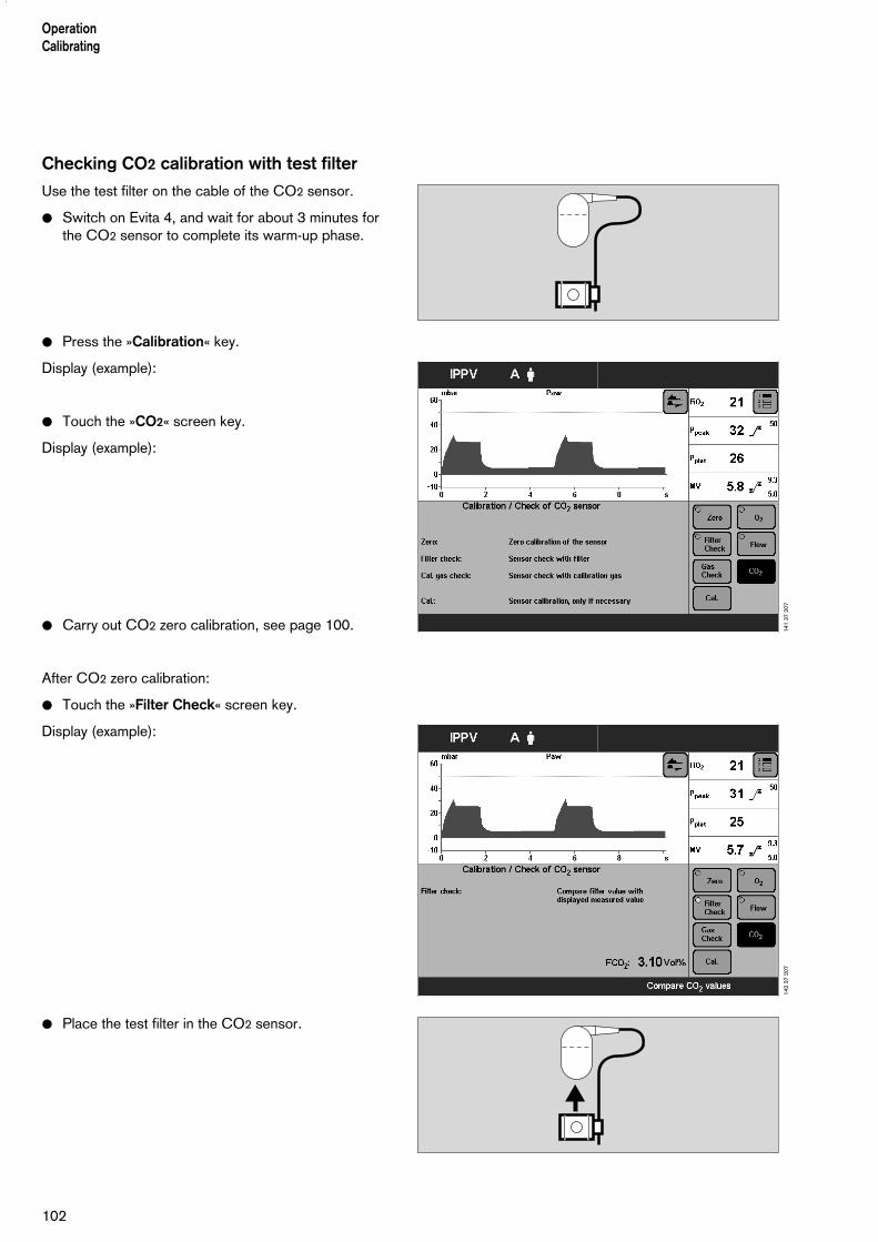
102
OperationCalibrating
Checking CO2 calibration with test filter
Use the test filter on the cable of the CO2 sensor.
● Switch on Evita 4, and wait for about 3 minutes forthe CO2 sensor to complete its warm-up phase.
● Press the »Calibration« key.
Display (example):
● Touch the »CO2« screen key.
Display (example):
● Carry out CO2 zero calibration, see page 100.
After CO2 zero calibration:
● Touch the »Filter Check« screen key.
Display (example):
● Place the test filter in the CO2 sensor.
141
37 2
0714
2 37
207

103
OperationCalibrating
4,1 Vol%
The screen displays the test value of the CO2 concen-tration FCO2.This value must agree to within ±3 Vol.% with the speci-fication on the test filter.Example: 4.1 Vol.% on the filter:permitted value range: 3.8 to 4.4 Vol.%
If the test value is outside the permitted tolerance, thetest gas must be checked or calibrated.
● Push the CO2 sensor back on to the cuvette.
Checking CO2 calibration with calibration gas
– if the specified calibration value was not met whentesting with the test filter
– at least once per half-year.
● Switch on Evita 4. Wait about 3 minutes for the CO2
sensor to complete its warm-up phase.
● Press the »Calibration« key.
Display (example):
● Touch the »CO2« screen key.
141
37 2
07

OperationCalibrating
104
2
1
3
Display (example):
● Carry out CO2 zero calibration, see page 100.
After completing CO2 zero calibration:
● Touch the »Gas Check« screen key.
● Connect the calibration gas supply. Use the cuvette from the calibration set!
1 Connect the calibration gas cylinder and cuvette ofthe calibration set to the hose.
2 Remove the CO2 sensor from its park bracket and fitit to the calibration set cuvette.
● Read the CO2, O2 and N2O concentrations (Vol.%)of the calibration gas from the test cylinder.
3 Calibration gas e.g.: 5 Vol.% CO2
95 Vol.% N2
● Enter these concentration values with the on-screenparameter setting knobs.Touch the relevant screen knob.Enter the concentration = turn rotary knob. If the calibration gas consists only of CO2 and N2, set the O2 and N2O concentrations to 0.
● Touch the »Start« screen key.
The CO2 concentration FCO2 is displayed on-screen.
After about 10 seconds, the value of FCO2 must matchto within ±0.2 Vol.% the CO2 content of the calibrationgas.
If the calibration value is outside the permitted tolerance,the CO2 sensor must be recalibrated with test gas.
● Push CO2 sensor back on the cuvette.
146
37 2
07
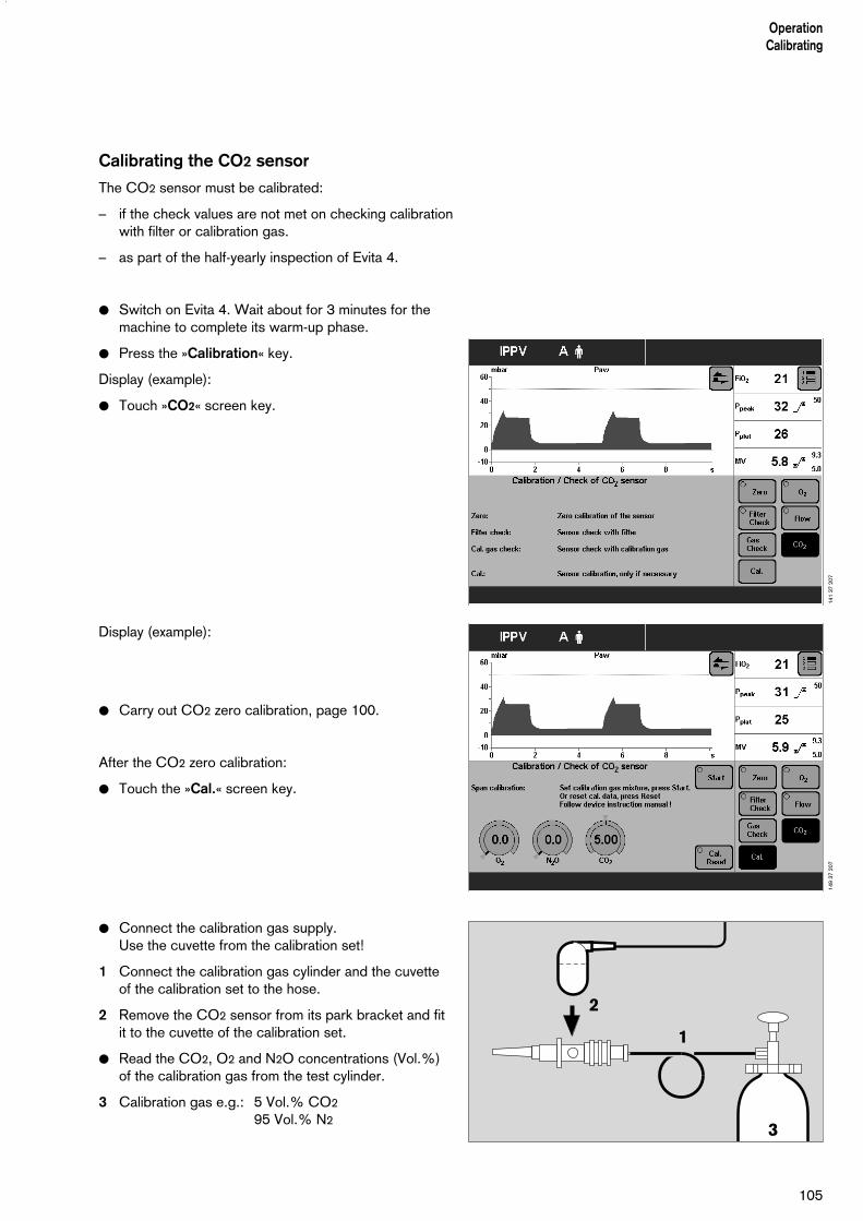
105
OperationCalibrating
2
1
3
Calibrating the CO2 sensor
The CO2 sensor must be calibrated:
– if the check values are not met on checking calibrationwith filter or calibration gas.
– as part of the half-yearly inspection of Evita 4.
● Switch on Evita 4. Wait about for 3 minutes for themachine to complete its warm-up phase.
● Press the »Calibration« key.
Display (example):
● Touch »CO2« screen key.
Display (example):
● Carry out CO2 zero calibration, page 100.
After the CO2 zero calibration:
● Touch the »Cal.« screen key.
● Connect the calibration gas supply.Use the cuvette from the calibration set!
1 Connect the calibration gas cylinder and the cuvetteof the calibration set to the hose.
2 Remove the CO2 sensor from its park bracket and fitit to the cuvette of the calibration set.
● Read the CO2, O2 and N2O concentrations (Vol.%)of the calibration gas from the test cylinder.
3 Calibration gas e.g.: 5 Vol.% CO2
95 Vol.% N2
141
37 2
0714
9 37
207

106
OperationCalibrating
● Enter these concentration values with the screenknobs.Touch the relevant screen knob.Enter the concentration = turn rotary knob. If the calibration gas consists only of CO2 and N2, setthe O2 and N2O concentrations to 0.
● Touch the »Start« screen key.
During calibration, the following message is displayed onthe screen:
CO2 calibration. Please wait
Evita 4 carries out calibration and confirms with themessage:
CO2 calibration ok
Failed calibration is indicated by the device with themessage:
CO2 calibration interruptedorCO2 calibration not ok
Repeat the calibration of the CO2 sensor.
Resetting CO2 calibration
– If calibration with calibration gas was unsuccessful,the factory-set calibration value can initially be used.
● Press the »Calibration« key.
● Touch the »CO2« screen key.
● On the CO2 calibration side, touch the »Cal.« screenkey and then touch the »Alarm Reset« screen key.
After about 5 seconds, resetting is complete, and thefactory-set calibration value is active.
Recover the correct calibration as soon as possible!
149
37 2
07

Contents
Sound................................................................................................... 108Adjusting the volume of the alarm tone....................................................108
Screen...................................................................................................109Selecting displayed measured values..................................................... 109Selecting displayed curves..................................................................... 111Selecting displayed trends......................................................................112
Ventilation............................................................................................. 113Selecting ventilation modes.................................................................... 113Selecting Pmax pressure limit.................................................................115Selecting AutoFlow as start-up ventilation mode...................................116Apnoea ventilation On/Off...................................................................... 117Selecting patient mode...........................................................................118Start-up values for ventilation parameters and alarm limits.......................119Setting start-up values for ventilation parameters »VT, f«..........................119Setting start-up values for ventilation parameters »Pressure, O2, I:E«..... 121Leakage compensation On/Off...............................................................122Setting start-up values for alarm limits.....................................................123
System Defaults................................................................................... 124Setting external interface........................................................................ 124Setting time and date............................................................................. 125Setting language and units..................................................................... 125Service diagnosis...................................................................................126
107
ConfigurationContents
Configuration

108
ConfigurationSound
Sound
Adjusting the volume of the alarm tone
● Press the »Configuration« key.
● Touch the »Sound« screen key.
Display (example):
● Touch the »Loudness« screen key.
Display (example):
● Adjust volume = Turn rotary knob.The band displayed on the screen shows the currentsetting between minimum and maximum.
● Confirm setting = press rotary knob.
After confirmation, the alarm tone is sounded to testthe volume.
152
37 2
0715
3 37
207

109
ConfigurationScreen
Screen
Selecting displayed measured values
Evita 4 displays a group of 4 measured values in theright-hand field of each screen page.
A second or third group can be displayed by touching the » « key. These groups can be put together in theconfiguration page.
● Press the »Configuration« key.
● Touch the »Screen« screen key.
Display (example):
● Touch the »Values« screen key.
Display (example):
123
154
37 2
0715
5 37
207
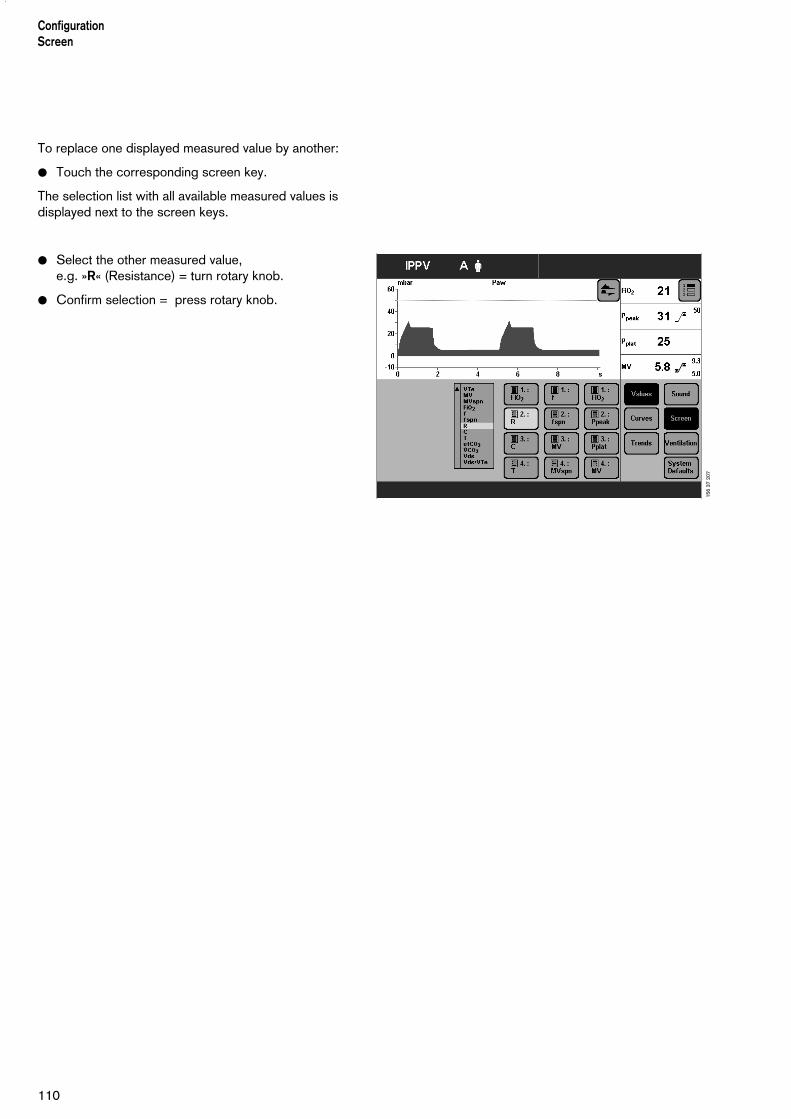
110
ConfigurationScreen
To replace one displayed measured value by another:
● Touch the corresponding screen key.
The selection list with all available measured values isdisplayed next to the screen keys.
● Select the other measured value,e.g. »R« (Resistance) = turn rotary knob.
● Confirm selection = press rotary knob.
156
37 2
07
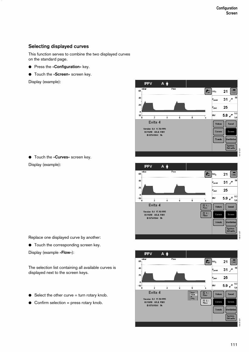
111
ConfigurationScreen
Selecting displayed curves
This function serves to combine the two displayed curveson the standard page.
● Press the »Configuration« key.
● Touch the »Screen« screen key.
Display (example):
● Touch the »Curves« screen key.
Display (example):
Replace one displayed curve by another:
● Touch the corresponding screen key.
Display (example »Flow«):
The selection list containing all available curves isdisplayed next to the screen keys.
● Select the other curve = turn rotary knob.
● Confirm selection = press rotary knob.
157
37 2
0715
8 37
207
159
37 2
07

112
ConfigurationScreen
Selecting displayed trends
This function serves to select 8 measured values that arestored by Evita 4 as a trend.
● Press the »Configuration« key.
● Touch the »Screen« key.
Display (example):
● Touch the »Trends« screen key.
Display (example):
To replace one displayed trend by another:
● Touch the relevant screen key.
Display (example: »Trend 1:MV«):
The selection list containing all available measured valuesis displayed next to the screen keys.
● Select the other measured value, e.g. »FiO2« for thetrend display = turn rotary knob.
● Confirm selection = press rotary knob.
160
37 2
0716
1 37
207
162
37 2
07
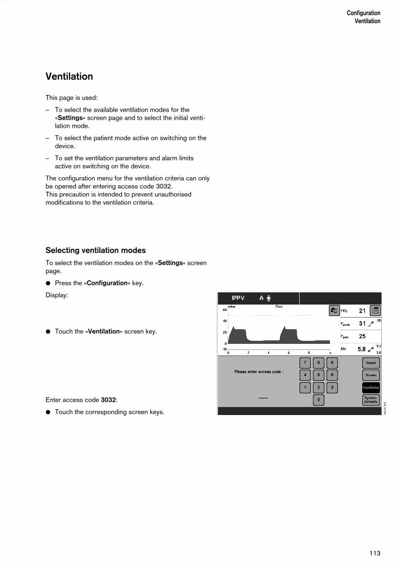
113
ConfigurationVentilation
Ventilation
This page is used:
– To select the available ventilation modes for the»Settings« screen page and to select the initial venti-lation mode.
– To select the patient mode active on switching on thedevice.
– To set the ventilation parameters and alarm limitsactive on switching on the device.
The configuration menu for the ventilation criteria can onlybe opened after entering access code 3032.This precaution is intended to prevent unauthorisedmodifications to the ventilation criteria.
Selecting ventilation modes
To select the ventilation modes on the »Settings« screenpage.
● Press the »Configuration« key.
Display:
● Touch the »Ventilation« screen key.
Enter access code 3032:
● Touch the corresponding screen keys. 163
37 2
07
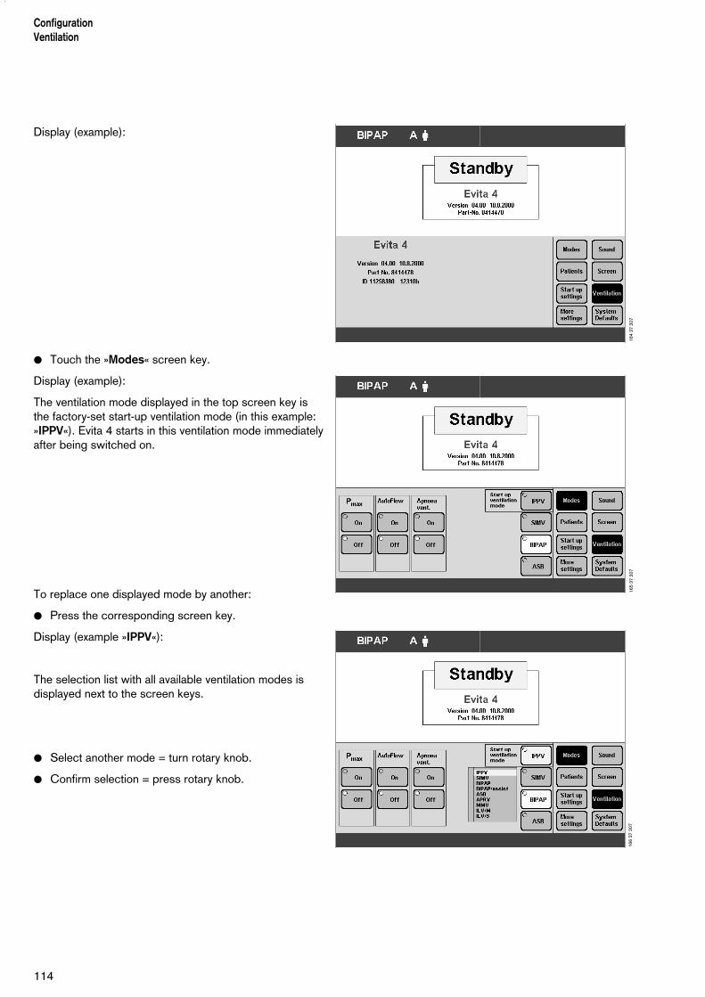
114
ConfigurationVentilation
Display (example):
● Touch the »Modes« screen key.
Display (example):
The ventilation mode displayed in the top screen key isthe factory-set start-up ventilation mode (in this example:»IPPV«). Evita 4 starts in this ventilation mode immediatelyafter being switched on.
To replace one displayed mode by another:
● Press the corresponding screen key.
Display (example »IPPV«):
The selection list with all available ventilation modes isdisplayed next to the screen keys.
● Select another mode = turn rotary knob.
● Confirm selection = press rotary knob.
164
37 2
0716
5 37
207
166
37 2
07

115
ConfigurationVentilation
Selecting Pmax pressure limit
– This function serves to limit the ventilation pressure inventilation modes IPPV, SIMV, MMV.
● Press »Configuration« key.
Display (example):
● Touch »Ventilation« screen key.
Enter access code 3032:
● Touch the corresponding screen keys.
Display (example):
● Touch the »Modes« screen key.
Display (example):
● Touch the screen key Pmax »On«.
● Confirm selection = press rotary knob.Pmax pressure limiting is selected.
The »Pmax« screen knob is displayed on the »Settings«screen page.
163
37 2
0716
8 37
207
169
37 2
07

116
ConfigurationVentilation
Selecting AutoFlow as start-up ventilationmode
– For automatically setting the AutoFlow ventilation option after switching on the apparatus.
The user can define whether the additional "AutoFlow " option is active or not after switching on.
● Press »Configuration« key.
● Touch »Ventilation« screen key.
Display (example):
Enter access code 3032:
● Touch the corresponding screen keys.
Display (example):
● Touch the »Modes« screen key.
Display (example):
To activate AutoFlow in the start-up ventilation mode:
● Touch the »On« screen key
● Confirm selection = press rotary knob.The AutoFlow option will be automatically activated the next time the apparatus is switched on.
163
37 2
0717
1 37
207
172
37 2
07
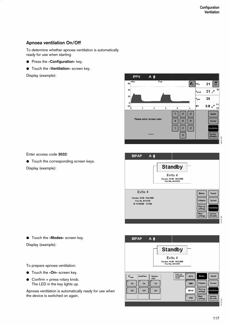
Apnoea ventilation On/Off
To determine whether apnoea ventilation is automaticallyready for use when starting
● Press the »Configuration« key.
● Touch the »Ventilation« screen key.
Display (example):
Enter access code 3032:
● Touch the corresponding screen keys.
Display (example):
● Touch the »Modes« screen key.
Display (example):
To prepare apnoea ventilation:
● Touch the »On« screen key.
● Confirm = press rotary knob.The LED in the key lights up.
Apnoea ventilation is automatically ready for use whenthe device is switched on again.
117
ConfigurationVentilation
163
37 2
0717
4 37
207
175
37 2
07
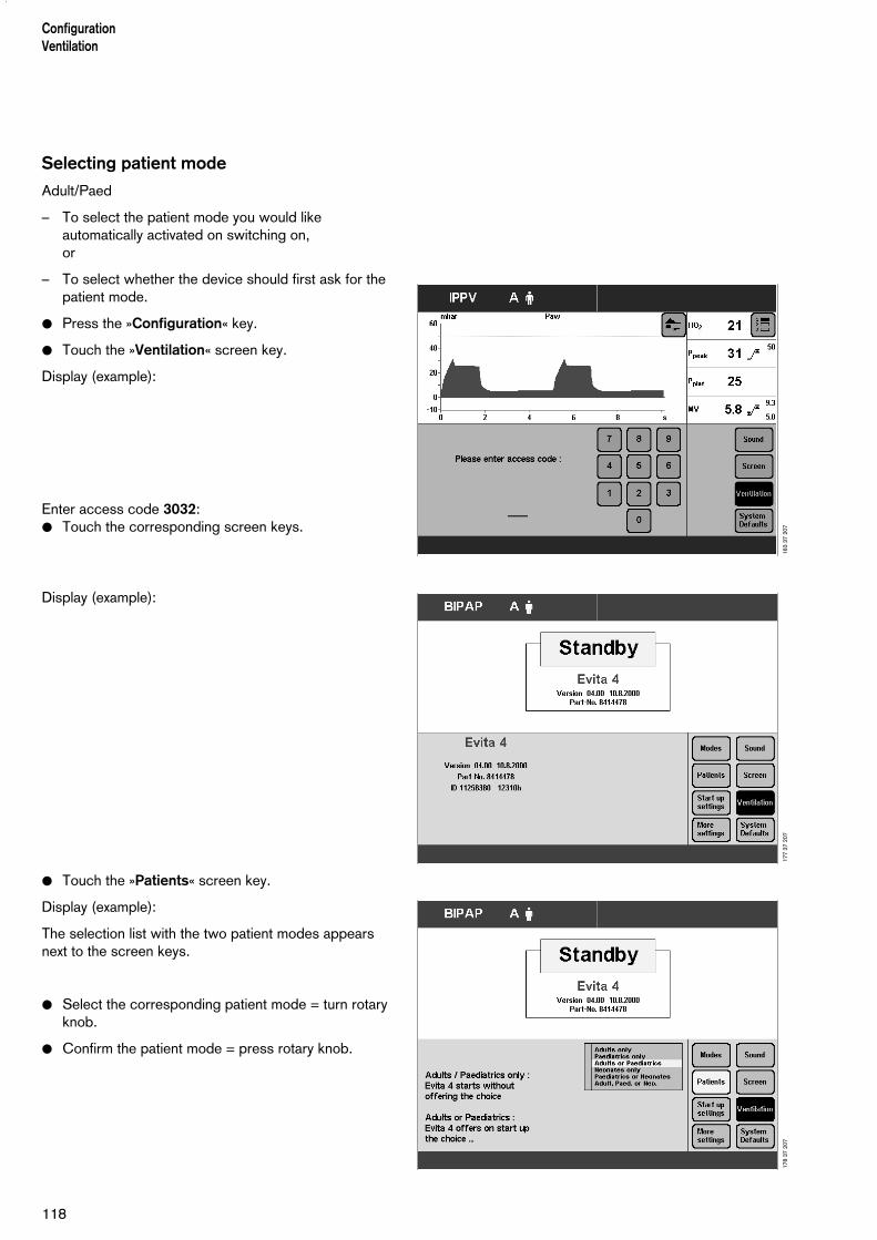
ConfigurationVentilation
118
Selecting patient mode
Adult/Paed
– To select the patient mode you would likeautomatically activated on switching on,or
– To select whether the device should first ask for thepatient mode.
● Press the »Configuration« key.
● Touch the »Ventilation« screen key.
Display (example):
Enter access code 3032:● Touch the corresponding screen keys.
Display (example):
● Touch the »Patients« screen key.
Display (example):
The selection list with the two patient modes appearsnext to the screen keys.
● Select the corresponding patient mode = turn rotary knob.
● Confirm the patient mode = press rotary knob.
163
37 2
0717
7 37
207
178
37 2
07
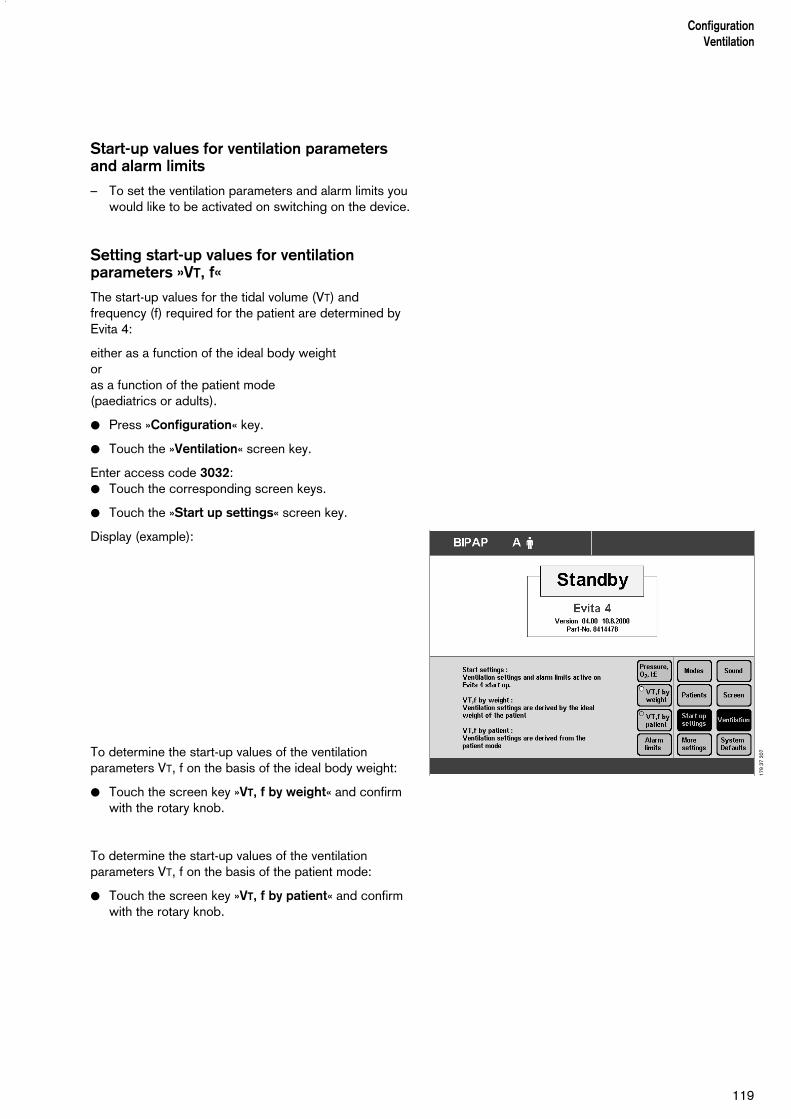
119
ConfigurationVentilation
Start-up values for ventilation parametersand alarm limits
– To set the ventilation parameters and alarm limits youwould like to be activated on switching on the device.
Setting start-up values for ventilationparameters »VT, f«
The start-up values for the tidal volume (VT) andfrequency (f) required for the patient are determined byEvita 4:
either as a function of the ideal body weightor as a function of the patient mode(paediatrics or adults).
● Press »Configuration« key.
● Touch the »Ventilation« screen key.
Enter access code 3032:● Touch the corresponding screen keys.
● Touch the »Start up settings« screen key.
Display (example):
To determine the start-up values of the ventilationparameters VT, f on the basis of the ideal body weight:
● Touch the screen key »VT, f by weight« and confirmwith the rotary knob.
To determine the start-up values of the ventilationparameters VT, f on the basis of the patient mode:
● Touch the screen key »VT, f by patient« and confirmwith the rotary knob.
179
37 2
07

ConfigurationVentilation
120
Start-up values »VT, f« dependent on ideal weight.The values are selected with reference to the Radfordnomogram:
The hospital-specific start-up values can be entered inthe table.
Start-up values »VT, f« dependent on patient mode.
The hospital-specific start-up values can be entered inthe table.
To change the start-up values of »VT, f«:
● Touch the screen key of the parameter to bechanged.
● Change value = turn rotary knob.
● Confirm value = press rotary knob.
If you wish to return to the factory settings:
● Touch »Dräger Reset« screen key.
Weight
kg Tidal volume VTmL
Ventilation frequency f bpm
Tidal volume VTmL
Ventilation frequency f bpm
3 20 30 ...................................... ......................................
15 110 26 ...................................... ......................................
65 450 13 ...................................... ......................................
100 700 10 ...................................... ......................................
Factory settings Hospital-specific settings
Tidal volume VTmL
Ventilation frequency f bpm
Tidal volume VTmL
Ventilation frequency f bpm
Paed. 50 29 ...................................... ......................................
Adults 500 12 ...................................... ......................................
Factory settings Hospital-specific settingsPatientmode
180
37 2
07
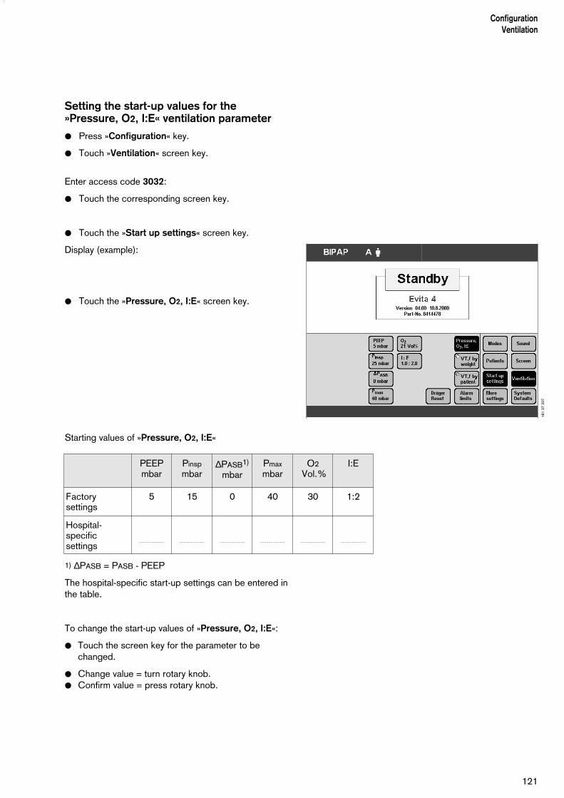
121
ConfigurationVentilation
Setting the start-up values for the »Pressure, O2, I:E« ventilation parameter
● Press »Configuration« key.
● Touch »Ventilation« screen key.
Enter access code 3032:
● Touch the corresponding screen key.
● Touch the »Start up settings« screen key.
Display (example):
● Touch the »Pressure, O2, I:E« screen key.
Starting values of »Pressure, O2, I:E«
1) ∆PASB = PASB - PEEP
The hospital-specific start-up settings can be entered inthe table.
To change the start-up values of »Pressure, O2, I:E«:
● Touch the screen key for the parameter to be changed.
● Change value = turn rotary knob.● Confirm value = press rotary knob.
PEEPmbar
Pinspmbar
∆PASB1)
mbarPmaxmbar
O2 Vol.%
I:E
Factorysettings
5 15 0 40 30 1:2
Hospital-specificsettings
........................ ........................ ........................ ........................ ........................ ........................18
1 37
207

Leakage compensation On/Off
The automatic leakage compensation function is used bythe device to compensate leakages of up to 100 % of theset tidal volume in all volume-controlled ventilation modes.
The selection "leakage compensation on/off" is savedand reactivated when the device is restarted.
● Press the »Configuration« key.
● Touch the »Ventilation« screen key.Enter access code 3032.
● Touch the corresponding screen keys.
● Touch the »More settings« screen key.
Display:
● Touch the »Leak Comp.« screen key.
● Touch the »On« or »Off« screen key.
● Confirm = press rotary knob. The selected key ishighlighted by the yellow LED.
_____________
1) For a detailed description of the leakage compensation function,refer to the Annex, page 172.
ConfigurationVentilation
122
182
37 2
07
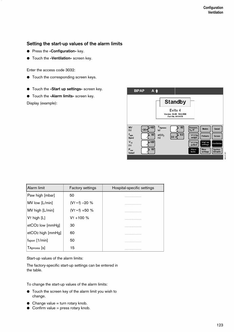
123
ConfigurationVentilation
Setting the start-up values of the alarm limits
● Press the »Configuration« key.
● Touch the »Ventilation« screen key.
Enter the access code 3032:
● Touch the corresponding screen keys.
● Touch the »Start up settings« screen key.
● Touch the »Alarm limits« screen key.
Display (example):
Start-up values of the alarm limits:
The factory-specific start-up settings can be entered inthe table.
To change the start-up values of the alarm limits:
● Touch the screen key of the alarm limit you wish to change.
● Change value = turn rotary knob.● Confirm value = press rotary knob.
Alarm limit Factory settings Hospital-specific settings
Paw high [mbar] 50 ......................................
MV low [L/min] (VT ● f) –20 % ......................................
MV high [L/min] (VT ● f) +50 % ......................................
VT high [L] VT +100 % ......................................
etCO2 low [mmHg] 30 ......................................
etCO2 high [mmHg] 60 ......................................
fspon [1/min] 50 ......................................
TApnoea [s] 15 ......................................
183
37 2
07
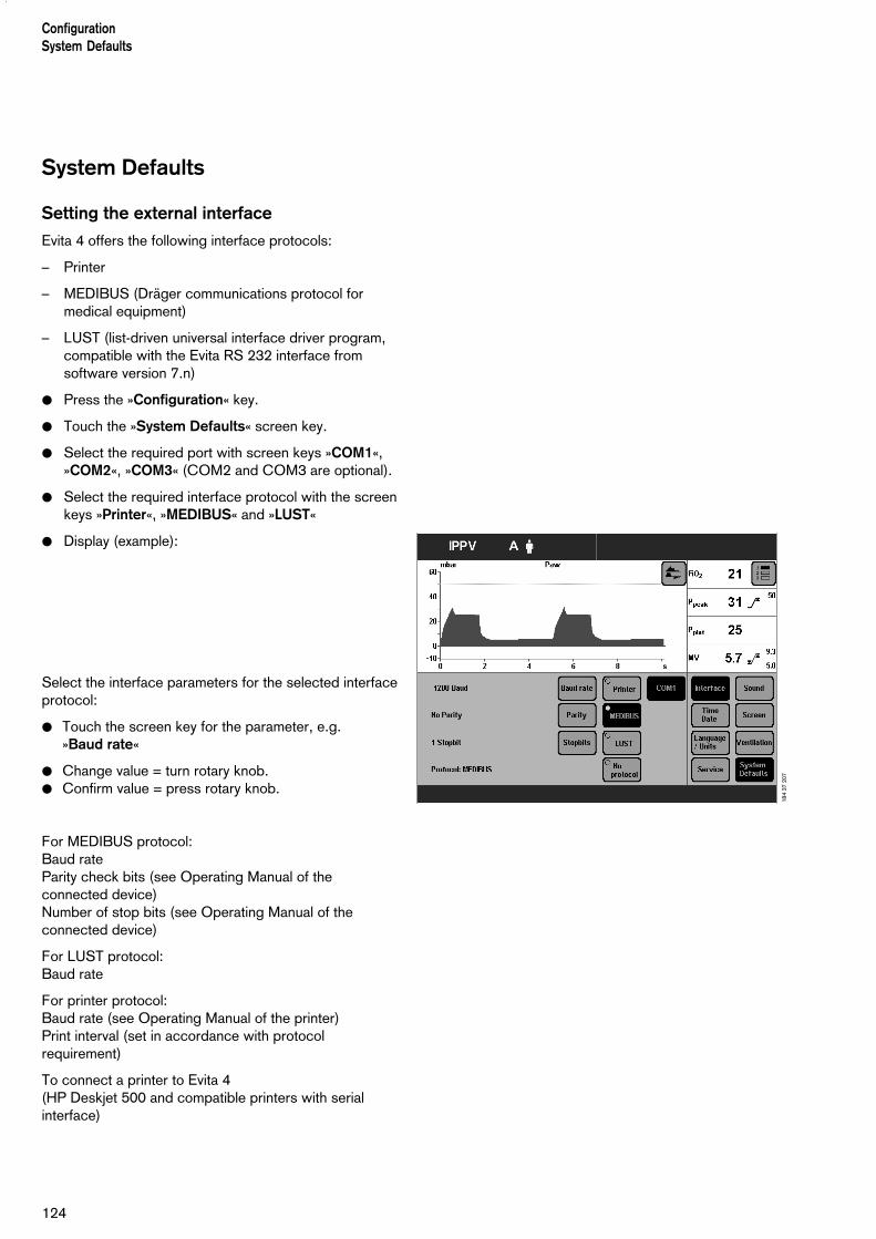
ConfigurationSystem Defaults
124
System Defaults
Setting the external interface
Evita 4 offers the following interface protocols:
– Printer
– MEDIBUS (Dräger communications protocol formedical equipment)
– LUST (list-driven universal interface driver program,compatible with the Evita RS 232 interface fromsoftware version 7.n)
● Press the »Configuration« key.
● Touch the »System Defaults« screen key.
● Select the required port with screen keys »COM1«,»COM2«, »COM3« (COM2 and COM3 are optional).
● Select the required interface protocol with the screenkeys »Printer«, »MEDIBUS« and »LUST«
● Display (example):
Select the interface parameters for the selected interfaceprotocol:
● Touch the screen key for the parameter, e.g. »Baud rate«
● Change value = turn rotary knob.● Confirm value = press rotary knob.
For MEDIBUS protocol:Baud rateParity check bits (see Operating Manual of theconnected device)Number of stop bits (see Operating Manual of theconnected device)
For LUST protocol:Baud rate
For printer protocol:Baud rate (see Operating Manual of the printer)Print interval (set in accordance with protocolrequirement)
To connect a printer to Evita 4(HP Deskjet 500 and compatible printers with serialinterface)
184
37 2
07

125
ConfigurationSystem Defaults
At a programmable regular interval (0 to 60 minutes), allimportant measured values of the Evita 4 and all settingsmodified since the last printout are automatically printedout. If the print time interval is set to 0 no printout occurs.
Regardless of the selected time interval, all alarms areprinted out when the alarm conditions occur.
In addition, printout can be manually started by pressingthe »Printer« key. The time interval in progress will remainunaffected.
Setting time and date
● Press »Configuration« key.
● Touch »System Defaults« screen key and
● touch »Time Date« screen key.
Display (example):
● Change value in cursor (Example [95]) = turn rotary knob.
● Confirm value = press rotary knob.
Selecting language and units
– To select the desired language for the screen texts,
– To select the units for pressure and CO2 concen-tration:
● Press »Configuration« key.
● Touch the »System Defaults« screen key.
Display (example):
Select language:
● Touch the »Language/Units« screen key.
● Touch the »Language« screen key.
● Select language = turn rotary knob.● Confirm language = press rotary knob.
185
37 2
0718
6 37
207
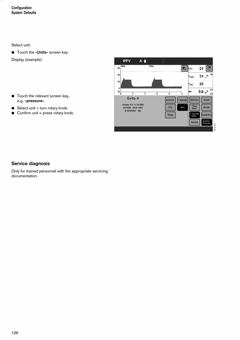
ConfigurationSystem Defaults
126
Select unit:
● Touch the »Units« screen key.
Display (example):
● Touch the relevant screen key,e.g. »pressure«.
● Select unit = turn rotary knob.● Confirm unit = press rotary knob.
Service diagnosis
Only for trained personnel with the appropriate servicingdocumentation.
187
37 2
07

Contents
Troubleshooting....................................................................................128
127
TroubleshootingContents
Troubleshooting

Troubleshooting
Alarm messages in the alarm display field are displayed inhierarchical order.If, for example, two faults are detected at the same time,the more critical of the two is displayed.
The priority for alarm messages is marked by exclamationmarks:Warning = Message with top priority !!!Caution = Message with medium priority !!Advisory = Message with low priority !
In the table below, the messages are listed in alpha-betical order.The table should help you identify the cause of any alarm,and to ensure rapid remedy of the problem.
128
Troubleshooting
Message Cause Remedy
Air supply down !!! Air supply pressure too low. Make sure pressure is greater than 3 bar.
Air supply down ! Air supply pressure too low.Air supply pressure not required when FiO2 = 100 Vol.%.
Make sure pressure is greater than 3 bar.
Air supply pressure high !! Air supply pressure too high. Ensure pressure is less than 6 bar.
Air supply pressure high ! Air supply pressure too high.Air supply is not needed for FiO2 = 100 Vol.%.
Ensure pressure is less than 6 bar.
Airway pressure high !!! The upper alarm limit for the airwaypressure has been exceeded. Thepatient is "fighting" the ventilator, cough.
Check patient condition,Check ventilation pattern,Correct alarm limit if necessary.
Ventilation hose buckled. Check hose system and tube.
Airway pressure low !!! Leaking cuff. Inflate cuff and perform leak test.
Leak or disconnection. Check hose system for tight connections.Check that the expiration valve isproperly engaged.
Apnoea !!! Patient's spontaneous breathing hasstopped.
Apply controlled ventilation.
Stenosis Check condition of patient. Check tube.
Flow sensor not calibrated or faulty. Calibrate flow sensor. Replace ifnecessary.
Apnoea ventilation !! Due to detected apnoea, the systemhas switched over automatically tomandatory ventilation.
Check ventilation procedure. Return tothe original ventilation procedure with»Alarm Reset«.
Check condition of patient. Check tube.
ASB > 1.5 s ! Only appears in paediatric mode. The ASB cycle has been switched off 3 times due to time limitation.
Test ventilation system for leaks.
ASB > 4 s !!! Only appears in adult mode. The ASB cycle has been switched off 3 times due to time limitation.
Test ventilation system for leaks.

129
Troubleshooting
Message Cause Remedy
Check frequency !ILV Slave
Message on slave device
The frequency (breathing rate) of themaster and slave devices differ by morethan 12 %.
Adjust the frequency of the slave deviceto that of the master.
Check settings !! Power interruption while setting aventilation pattern or the alarm limits.
Check pattern of ventilation and alarmlimits. Confirm message with key »Alarm Reset«.
Clean CO2 cuvette !!! Cuvette window dirty. Use clean cuvette.
Sensor window dirty. Clean CO2 sensor.
CO2 measurement inop !!! CO2 sensor faulty. Replace faulty CO2 sensor.
CO2 measurement incorrect. Call DrägerService.
CO2 monitoring off ! CO2 monitoring is switched off. Switch CO2 monitoring on again, page 95, or ensure adequate externalmonitoring without delay.
CO2 sensor ? !!! Probe of CO2 sensor withdrawn duringoperation.
Reinsert probe.
CO2 sensor not positioned on cuvette. Place CO2 sensor on cuvette.
CO2 sensor faulty. Replace defective CO2 sensor.
CO2 zero ? !!! Zero outside the permitted tolerance. Perform zero calibration, page 100.
Zero calibration unsuccessful. Perform CO2 zero calibration correctly,page 100.
Device failure !!! Device faulty. Call DrägerService.
etCO2 high !!! End-expiratory CO2 concentrationabove upper alarm limit.
Check condition of patient,check pattern of ventilation,correct alarm limit if necessary.
etCO2 low !!! End-expiratory CO2 concentrationbelow lower alarm limit.
Check condition of patient, check pattern of ventilation,correct alarm limit if necessary.
Evita Remote ? ! The Remote Pad has not been identified correctly.
Remove Remote Pad. Confirm message with key »AlarmReset«. Call DrägerService at the nextopportunity.
Evita Remote inop. ! Key pressed on Remote Pad duringself-test.
Confirm message with key »AlarmReset«. Remove Remote Pad andreconnect. Ensure that no key is pressedon the Remote Pad.
Remote Pad faulty. Confirm message with key »ResetCheck«. Remove Remote Pad. CallDrägerService at the next opportunity.
Execute device check !! Device check not performed. Perform device check, page 42.Confirm message with »Alarm Reset«key.

130
Troubleshooting
Message Cause Remedy
Exp. hold interrupted ! The »Exp. hold« key has been pressedfor more than 15 seconds.
Release the »Exp. hold« key.
Exp. valve inop. !!! Expiration valve not properly connectedto socket.
Push expiration valve firmly into socketuntil it clicks into place.
Flow sensor not calibrated or defective. Calibrate flow sensor, page 98, replace if necessary.
Expiration valve faulty. Replace expiration valve.
External Flow ! Evita 4 calculates the externally supplied flow when monitoring correctfunctioning of the flow measurement.
Deactivate calculation of the externalflow, see page 99.
Fan failure !!! Fan failure. Call DrägerService.
FiO2 high !!! O2 sensor not calibrated. Calibrate O2 sensor, page 97.
Faulty mixer function. Call DrägerService.
FiO2 low !!! O2 sensor not calibrated. Calibrate O2 sensor, page 97.
Faulty mixer function. Call DrägerService.
Flow measurement inop. !!! Water in flow sensor. Dry flow sensor.
Flow sensor faulty. Calibrate flow sensor, page 98, replace if necessary.
Flow measurement malfunction. Call DrägerService.
Flow monitoring off ! Flow monitoring is switched off. Switch on flow monitoring again, asdescribed on page 95, or immediatelyensure an adequate external monitorfunction.
Flow sensor ? !!! Flow sensor not fully inserted in rubberlip of expiration valve.
Insert flow sensor correctly.
Hard key xx failed !! Key xx (e.g. »g« ) can no longer bepressed.
Call DrägerService.
High frequency !!! Patient is breathing at a highspontaneous frequency
Check condition of patient,Check pattern of ventilation,Correct alarm limit if necessary.
ILV Sync. inop. !!!
Message on both devices
Frequency on master device less than 4 breaths per minute.
Set a higher frequency.
Call DrägerService.
Device defective. Call DrägerService.
Insp. hold interrupted ! The »Insp. hold« key was held downlonger than 15 seconds.
Release »Insp. hold« key.

131
Troubleshooting
Message Cause Remedy
Insp / Exp cycle failure !!! The device does not deliver any gas. Check the Pmax/PEEP setting.
Set an IPPV frequency of at least 4/min.
Increase TApnoea > alarm time.
Device faulty. Call DrägerService.
Key xx overused ? !! Key has been pressed several times in ashort period (e.g. »g«).
Confirm message with key »Alarm Reset« If this message occurs repeatedly, callDrägerService.
Key overused ? !! Due to very frequent key use, thescreen contents of the display arerepeatedly redrawn.
Confirm message with key »Alarm Reset«.
Brief communication failure between the display processor and mainprocessor.
Confirm message with key »Alarm Reset«. If this message occursagain, call DrägerService.
Leakage ! The measured leakage minute volumeMVleak is 20 % higher than the minutevolume measured on the expiration side.
Check that the hose connection isleakproof.Check that the tube is correctly fitted.
Loss of data !!! Lithium battery discharged. Call DrägerService.
Malfunction fan ! Temperature in machine too high. Check fan function, clean cooling-air filteror call DrägerService.
MEDIBUS COM. inop. ! The connector of the MEDIBUS cablewas unplugged during operation.
Plug the connector in again and secure it against disconnection with the twoscrews.
MEDIBUS cable defective. Use a new MEDIBUS cable.
Interface defective. Call DrägerService.
Mixer inop. !!! Mixer malfunction.FiO2 can deviate considerably.
Immediately ventilate with separatemanual ventilation device!Call DrägerService.
Multi functional board !inop.
The multi-functional board for operatingthe nurse call or Remote Pad is faulty.
Confirm message with key »AlarmReset«. Call DrägerService at the nextopportunity.
The original ventilation functions of Evita 4 are not affected. Correctfunctioning of the nurse call or RemotePad is not guaranteed, however: removethe nurse call and/or Remote Pad.
Multi functional board !!inop.
The multi-functional board for operatingthe nurse call or Remote Pad is faulty.
Confirm message with key »AlarmReset«. Call DrägerService at the nextopportunity.
The original ventilation functions of Evita 4 are not affected. Correctfunctioning of the nurse call or RemotePad is not guaranteed, however: removethe nurse call and/or Remote Pad.

Troubleshooting
132
Message Cause Remedy
MV high !!! The minute volume has exceeded theupper alarm limit.
Check condition of patient,check pattern of ventilation,correct alarm limit if necessary.
Flow sensor not calibrated or faulty..
Calibrate flow sensor, page 98, replace if necessary.
Water in flow sensor. Drain water trap in hose system.Dry flow sensor.
Machine malfunction. Call DrägerService.
MV low !!! The minute volume has fallen below thelower alarm limit.
Check condition of patient,check pattern of ventilation,correct alarm limit if necessary.
Stenosis..
Check condition of patient. Check tube.
Leak in breathing system. Establish leakproof breathing system.
Flow sensor not calibrated or faulty. Calibrate flow sensor, page 98, replace if necessary.
Machine malfunction. Call DrägerService.
Nebulisation interrupted !! Only in paediatric mode. Nebulisation isonly possible in pressure-controlledventilation or with AutoFlow .
Select the patient mode.Restart nebulisation.Acknowledge the alarm with»Alarm/Reset».
Only in paediatric mode, only forventilation with AutoFlow . Flow sensor not ready for measure-ment.
Switch on flow monitoring or calibrateflow sensor, page 98, or replace flowsensor or change mode.Restart nebulisation.Acknowledge the alarm with»Alarm/Reset»
Nebulizer on ! The medicament nebuliser is switchedon, page 88.
Switch off the medicament nebuliser if necessary, page 90.
O2 measurement inop. !!! O2 sensor provides invalid measuredvalues.
Calibrate O2 sensor, page 97, replace if necessary.
O2 measurement malfunction. Call DrägerService.
O2 monitoring off ! O2 monitoring switched off. Switch on O2 monitoring again, asdescribed on page 97, or immediatelyensure an adequate monitor function.
O2 supply down !!! O2 supply pressure too low. Make sure pressure is greater than 3 bar.
O2 supply down ! O2 supply pressure too low.O2 supply pressure is not requiredwhen FiO2 = 21 Vol.%.
Make sure pressure is greater than 3 bar.

133
Troubleshooting
Message Cause Remedy
O2 supply pressure high !! O2 supply pressure too high. Make sure pressure is less than 6 bar.
O2 supply pressure high ! O2 supply pressure too high.O2 supply pressure is not requiredwhen FiO2 = 21 Vol.%.
Make sure pressure is less than 6 bar.
PEEP high !!! Expiratory system obstructed. Check hose system and expiration valve.
Expiratory resistance is increasing. Check bacterial filter. Replace if necessary.
Machine faulty. Call DrägerService.
PEEP valve inop. !!! Internal PEEP valve faulty. Call DrägerService.
Pressure limited ! Pmax pressure limit is active. Check condition of patient,check pattern of ventilation,correct setting if necessary.
Pressure meas. inop. !!! Fluid in expiration valve. Replace expiration valve, page 130, then clean and dry.
Pressure measurement malfunction. Call DrägerService.
Standby activated !!! Evita 4 has been switched to standby. Confirm standby with »Alarm Reset« key.
Temperature high !!! Breathing gas temperature higher than40 ºC.
Switch off humidifier.
Temperature meas. inop. !!! Temperature sensor faulty. Fit new temperature sensor, see page 33.
Temperature sensor ? !!! Temperature sensor probe has beendisconnected during operation.
Reconnect probe.
Sensor cable broken. Fit new temperature sensor.
Tidal volume high !!! The upper alarm limit of the appliedinspiratory tidal volume VT has beenexceeded during three consecutiveventilation strokes.
Check condition of patient,check pattern of ventilation,correct alarm limit if necessary.
Leak or disconnection. Check that hose system connections areleakproof.
Tidal volume high ! The inspiratory tidal volume VT hasexceeded the upper alarm limit.
Check condition of patient,check pattern of ventilation,correct alarm limit if necessary.
Leak or disconnection. Check that hose system connections areleakproof.
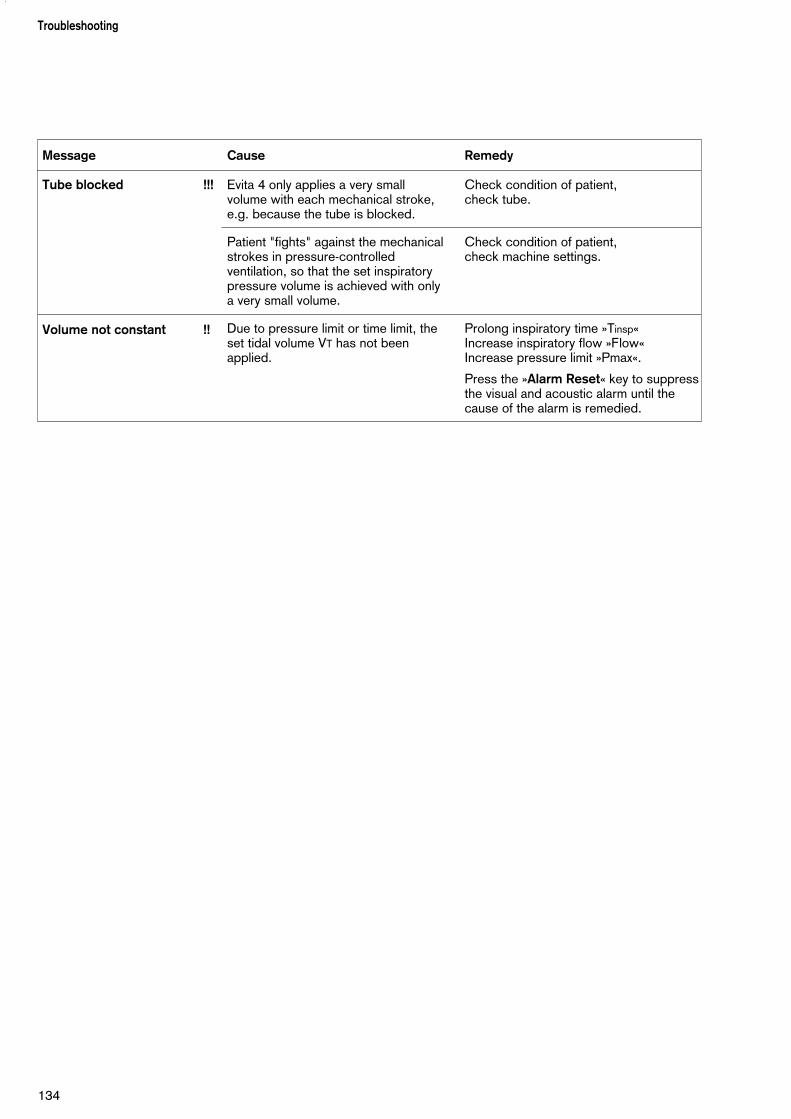
Troubleshooting
134
Message Cause Remedy
Tube blocked !!! Evita 4 only applies a very small volume with each mechanical stroke,e.g. because the tube is blocked.
Check condition of patient, check tube.
Patient "fights" against the mechanicalstrokes in pressure-controlledventilation, so that the set inspiratorypressure volume is achieved with only a very small volume.
Check condition of patient, check machine settings.
Volume not constant !! Due to pressure limit or time limit, theset tidal volume VT has not beenapplied.
Prolong inspiratory time »Tinsp«Increase inspiratory flow »Flow«Increase pressure limit »Pmax«.
Press the »Alarm Reset« key to suppressthe visual and acoustic alarm until thecause of the alarm is remedied.
Contents
Dismantling...........................................................................................136CO2 sensor (optional)............................................................................ 136Temperature sensor............................................................................... 136Medicament nebuliser............................................................................ 137Ventilation hoses.................................................................................... 137Flow sensor........................................................................................... 137Expiration valve...................................................................................... 138Humidifier.............................................................................................. 138
Disinfecting/Cleaning........................................................................... 139
Assembling........................................................................................... 142Fitting expiration valve............................................................................ 142
Before Reusing on Patient....................................................................143
Maintenance Intervals ..........................................................................143Replacing cooling filter........................................................................... 144Disposing of batteries and O2 sensors................................................... 144Removing/fitting ambient air filter............................................................144Correct disposal of apparatus................................................................ 145
135
PreparingContents
Preparing

Dismantling
Clean and prepare the machine after each patient.
Recommendation:Change the hose system and expiration valve every 24 hours. Keep the replacement systems ready.
● Switch off the ventilator and humidifier, and removetheir power plugs.
● Drain the water traps and ventilation hoses.
● Drain the water container of the humidifier.
CO2 sensor (optional)
1 Remove from the cuvette. Unplug the connector fromthe back of the unit.
2 Remove the cuvette of the CO2 sensor from the Y-piece.
3 Remove the catheter cone from the cuvette.
● Prepare the CO2 sensor for wipe disinfecting.
● Prepare the cuvette for disinfecting and cleaning inthe autoclave.
Temperature sensor
4 Remove from the Y-piece or from the mounting ofhose set K. Do not pull the cable.
● Unplug the connector from the back of the Evita 4.
● Prepare the temperature sensor for wipe disinfecting.
The temperature sensor is not suitable forautoclaving or immersion in a disinfectant bath.
1
2
3
136
PreparingDismantling
4
To avoid endangering hospital staff and otherpatients, the ventilator must be disinfected andcleaned whenever it has been used. Follow acceptedhospital procedures for disinfecting contaminatedparts (protective clothing, eyewear, etc.).

Medicament nebuliser (option)
1 Remove the nebuliser hose from the nebuliser andfrom the port on the device.
2 Remove the medicament nebuliser from the hosesystem or
2 Dismantle the medicament nebuliser from thepaediatric hose system.
3 Remove the catheter connector (ISO cone ø15 / ø11)from the inlet.
4 Remove adapter (ISO cone ø22 / ø11) from theoutlet.
5 Remove corrugated hose from the adapter.
● Dismantle the medicament nebuliser in accordancewith its specific Instructions for Use.
● Prepare the individual parts of the medicamentnebuliser and the adapting components fordisinfecting and cleaning in the autoclave.
Ventilation hoses
● Remove from the adapters and ports.
● Remove the water traps from the ventilation hoses.Remove the collecting jars from the water traps.
● Prepare the ventilation hoses, water traps and theircollecting jars and the Y-piece for cleaning in theautoclave.
Flow sensor
● Tilt the control unit upward.
6 Push the flow sensor to the left as far as it will go and
7 pull out.
The flow sensor cannot be disinfected/cleaned byautoclaving and cannot be sterilised by the hot steammethod.
● Disinfect the flow sensor for about 1 hour in 70 %ethanol solution.
Expose the sensor to air for at least 30 minutes.Otherwise residual alcohol could damage thesensor beyond control due to ignition duringcalibration.
● The flow sensor may be reused as long as calibrationcan be carried out successfully.
137
PreparingDismantling
12
5 4
2 1
3
76

Expiration valve
1 Push the catch to the right while at the same time
2 pulling out the expiration valve.
If the expiration valve is fitted with an optional water trap:
● Pull off the collecting jar.
Only strip down the expiration valve if badly soiled.
● Unscrew the stopper by hand and remove togetherwith the diaphragm.
● Do not disassemble the expiration valve any further.
● Prepare the expiration valve for disinfecting andcleaning by autoclave
and
● prepare the expiration valve for hot steam sterilisation.
● Place the open expiration valve in the basket so that itcannot be damaged by other parts.
Humidifier
● Dismantle in accordance with the specific Instructionsfor Use and prepare for disinfecting/sterilising.
PreparingDismantling
138
1
2

Disinfecting/Cleaning
Use surface disinfectants. For surface compatibility, usedisinfectants based on:– aldehydes,– quaternary ammonium compounds.
To avoid the possibility of damage to material, do not useany disinfectants based on:– alkylamine-based compounds– phenol-based compounds,– halogen-releasing compounds,– strong organic acids,– oxygen-releasing compounds.
For users in the Federal Republic of Germany, werecommend that only disinfectants on the current DGHMlist are used (DGHM: German Society for Hygiene andMicrobiology).The DGHM list (published by mhp-Verlag, Wiesbaden)also classifies each disinfectant by its active agents. For countries where the DGHM list is not available, werecommend the types of disinfectant given above.
Disinfectants often contain – besides their main activeagents – additives that can also damage materials. If in doubt, ask the supplier/manufacturer of thedisinfectant/ cleaning agent.A list of substances used is given on page 158.
Do not sterilise parts in ethylene oxide!
The screen is made of Plexiglas.● Do not handle with alcohol or agents containing
alcohol. Danger of cracking.
139
PreparingDisinfecting/Cleaning
To avoid endangering hospital staff and otherpatients, the ventilator must be disinfected andcleaned whenever it has been used. Follow acceptedhospital procedures for disinfecting contaminatedparts (protective clothing, eyewear, etc.).

Basic device without ventilation hoses, gasconnection hoses and temperature sensor
Wipe disinfect
● e.g. with Buraton 10 F or Terralin (Schülke & Mayr,Norderstedt).Comply with the manufacturer's instructions.
Cooling air filter, room air filter
● Filters must be cleaned or replaced when soiled or atthe latest after 4 weeks, see page 144.
CO2 Cuvette
● Wipe off dirt, in particular inside and outside thewindows, with disposable tissue and cotton buds.
● Disinfect with moist heat (93 °C/10 minutes) in acleaning and disinfecting machine. Use only cleaningagent.
Or:
● Disinfect in bath of disinfectant based on the listedactive substances, e.g. Cidex, Johnson & Johnson,Norderstedt.
Or:
● Steam-sterilise at 134 °C.
CO2 Sensor
● Wipe off dirt with cotton buds, in particular on thewindows of the CO2 sensor.
● Disinfect by wiping, e.g. with 70 % Ethanol.
PreparingDisinfecting/Cleaning
140
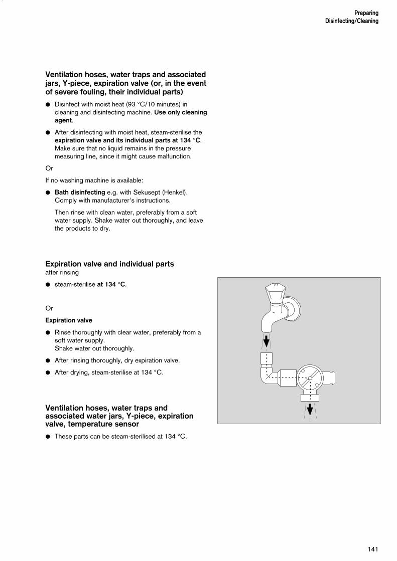
Ventilation hoses, water traps and associatedjars, Y-piece, expiration valve (or, in the eventof severe fouling, their individual parts)
● Disinfect with moist heat (93 °C/10 minutes) incleaning and disinfecting machine. Use only cleaningagent.
● After disinfecting with moist heat, steam-sterilise theexpiration valve and its individual parts at 134 °C.Make sure that no liquid remains in the pressuremeasuring line, since it might cause malfunction.
Or
If no washing machine is available:
● Bath disinfecting e.g. with Sekusept (Henkel).Comply with manufacturer's instructions.
Then rinse with clean water, preferably from a softwater supply. Shake water out thoroughly, and leavethe products to dry.
Expiration valve and individual partsafter rinsing
● steam-sterilise at 134 °C.
Or
Expiration valve
● Rinse thoroughly with clear water, preferably from asoft water supply.Shake water out thoroughly.
● After rinsing thoroughly, dry expiration valve.
● After drying, steam-sterilise at 134 °C.
Ventilation hoses, water traps andassociated water jars, Y-piece, expirationvalve, temperature sensor
● These parts can be steam-sterilised at 134 °C.
141
PreparingDisinfecting/Cleaning

Assembling
Mounting the expiration valve
The parts must be entirely dry to prevent malfunctioning.
● Hold stopper by the flange and place diaphragm onthe collar of the stopper. Be careful to fit the diaphragm properly.
● Insert stopper with diaphragm on top into the housingfrom below and screw in tightly.
If the expiration valve has an optional water trap:
● Fit the collecting jar.
Medicament nebuliser
● Assemble in accordance with separate Instructionsfor Use.
● Install, see page 89.
PreparingAssembling
142

Humidifier
● Assemble in accordance with separate Instructionsfor Use.
Before Reusing on Patient
● Assemble machine as described under "Preparation"on page 29 et seq..
● Carry out checks to ensure readiness for operation,see "Device Check" on page 42.
Maintenance Intervals
Clean and disinfect equipment and/or componentsbefore any maintenance procedures – and beforereturning for repair!
O2 sensor capsule Replace sensor capsule in eventof display message: O2 measurement inop and if calibration is impossible.Disposal, see page 144.
Ambient-air filter Clean or replace after 4 weeks,Cooling-air filter see page 144.
Replace every year. Dispose of with normal domesticwaste.
Filters in the com- To be replaced by trained servicepressed gas inlets personnel every 2 years.
Lithium battery To be replaced by trained servicefor data protection personnel every 2 years.
Disposal, see page 144.
Clock module To be replaced by trained service personnel after 6 years.
Pressure reducer Complete overhaul every 6 yearsby Dräger Service.
Equipment inspection Every 6 months by trained serviceand service personnel.
143
Preparing Before Reusing on Patient
Maintenance Intervals

Clean or replace cooling air filter– Filter must be cleaned or replaced when soiled or at
the latest after 4 weeksReplace after 1 year at the latest.
1 Remove cooling-air filter from its slot on the back ofmachine.
● Replace or clean in warm water with detergentadded; dry well.
● Insert cooling-air filter in slot, taking care not to crease it.
● Dispose of used cooling-air filter with domestic waste.
Correct disposal of batteries and O2 sensors
Batteries and O2 sensors:
● do not throw in a fire; risk of explosion!
● do not open using force; risk of corrosion!
● do not re-charge batteries.
Batteries and O2 sensors must be disposed of as specialwaste:
● Disposal must conform to local waste disposalregulations.Information may be obtained from the localenvironmental and public health authorities and fromapproved waste disposal companies.
Removing and reinserting ambient-air filter
– Filter must be cleaned or replaced when soiled or atthe latest after 4 weeksReplace filter every year.
1 If necessary, swivel port to the left.
2 Loosen screw with a coin, and remove the protectivecover.
3 Remove the ambient-air filter from the protectivecover.
● Push ambient-air filter under the lugs.
● Replace protective cover, and tighten screw with acoin.
● Dispose of used ambient-air filter with domestic waste.
1
PreparingMaintenance Intervals
144
1 2
3

Correct disposal of apparatus
– at the end of its useful life
After contacting the competent waste disposal company,hand over Evita 4 for appropriate disposal.The applicable legal regulations must be observed.
145
Preparing Maintenance Intervals

146

Contents
Control unit............................................................................................ 148Front connections.................................................................................. 149Back panel.............................................................................................150
147
What's whatContents
What is what

What's what
Control unit
1 Key for displaying the »Measured Values« screenpage.
2 Key for displaying the »Alarm Limit« screen page. For displaying the measured values and alarm limits,and for setting the alarm limits.
3 Key for displaying the »Settings« screen page. For setting the ventilation modes and ventilationparameters.
4 » « key for displaying help information for settings.
5 Red LED to indicate warnings
6 Yellow LED to indicate cautions and advisorymessages
7 »g« key for cancelling the acoustic alarm for 2 minutes.
8 »Stop« key for "freezing" curves.
9 »Alarm Reset« key for acknowledging alarmmessages.
10 »?« key for selecting the standard screen page.
11 »O« key for switching between operating and standby mode.
12 Central rotary dial-knob for selecting and confirmingsettings.
13 Key for displaying the »Configuration« screen page.
14 Key for displaying the »Calibration« screen page.
15 Key for displaying the »Special Procedures« screenpage. For measuring PEEPi and Occlusion Pressure.
16 Touch-sensitive screen for displaying application-specific screen pages.
17 » « key for manual printer logging.
18 » « key for switching the screen to bright or dark.
19 »Exp. hold« key for prolonging/holding expiration.
20 »Insp. hold« key for manual inspiration.
21 »O2 suction« key for oxygenation for bronchialsuction.
22 » « key for switching on the medicamentnebuliser.
148
What's what
7
9
8
11
10
22
21
20
17
16 15 14 13 12
1 2 3 4
19
18
56
MT-
156-
98e

Front connections
1 Flow sensor
2 Expiration valve with expiration port
3 Latch for expiration valve
4 Inspiratory port
5 Locking screw for protective cover (behind it: O2 sensor and ambient-air filter)
6 Connections for optional pressure measurement(not used)
7 Gas supply port for the medicament nebuliser
149
What's what
1 2 3 4 5
7 6

Back panel
1 Fan
2 Power switch with protective flap
3 »COM2«, »COM3« sockets for RS 232 and analoginterfaces (optional)
4 Connection » « for Remote Pad, optional
5 Connection » « for nurse call, optional
6 Cooling-air filter
7 ILV socket
8 Connection for oxygen
9 Connection for medical air
10 »Temp m « socket for temperature sensor
11 »CO2 m « socket for CO2 sensor
12 »Sync.« socket for C-Lock-ECG synchronisation for optional SpO2 measurement
13 »SpO2 m « socket for functional SpO2 measurement,optional
14 »COM1 RS232C« socket for RS 232 interface, e.g. for printer
15 Mains fuses
16 Connector for power cord
150
What's what
14 13 12 11 10 9 8
1 2 3 4 5 6
71615
MT-
628-
2000
Contents
Environmental conditions........................................................................152Settings................................................................................................. 152Performance data...................................................................................153Measured value displays........................................................................ 153Monitoring..............................................................................................155Operating data....................................................................................... 156Machine outputs.....................................................................................157Electromagnetic compatibility (EMC)...................................................... 158Classification..........................................................................................158UMDNS-Code....................................................................................... 158Materials used........................................................................................158
151
Technical DataContents
Technical Data

Technical Data
Environmental conditions
In operation Temperature 10 to 40 °C Atmospheric pressure 700 to 1060 hPa Rel. humidity 0 to 90 %
In storage Temperature –20 to 60 °C Atmospheric pressure 500 to 1060 hPa Rel. humidity 0 to 100 %
Settings
Ventilation frequency f 0 to 100/min
Inspiration time Tinsp 0.1 to 10 s
Tidal volume VT Paediatrics 0.02 to 0.3 L, BTPS*Accuracy ±10 % of set value, or ±10 mL,
whichever is greater.
Adults 0.1 to 2.0 L, BTPS*Accuracy ±10 % of set value, or ±25 mL,
whichever is greater.
Inspiratory Flow Paediatrics 6 to 30 L/minAdults 6 to 120 L/min
Inspiratory pressure Pinsp 0 to 80 mbar
Inspiratory pressure limit Pmax 0 to 100 mbar
O2 concentration 21 to 100 Vol.% Accuracy ±5 % of set value, or ±2 Vol.%,
whichever is greater.
Positive end-expiratory pressure PEEP or interm. PEEP 0 to 35 mbar
Trigger sensitivity 0.3 to 15 L/min
Pressure assist PASB 0 to 80 mbarRise time for pressure assist 0 to 2 s
Independent lung ventilation (ILV)Master with trigger / without triggerSlave synchr. / asynchr. / inverse I : E
––––––––––* BTPS = Body Temperature, Pressure, Saturated.
Measured values relating to the conditions of the patient lung: body temperature 37 ºC, steam-saturated gas, ambient pressure.
Technical Data
152

Performance Data
Control principle time-cycled, volume-constant, pressure-controlled
Intermittent PEEP frequency 2 cycles every 3 minutes
Medicament nebulisation for 30 minutes
Bronchial suctiondisconnection detection automaticreconnection detection automaticoxygen enrichment max. 3 minutesactive suction phase max. 2 minutesfinal oxygen enrichment 2 minutes
Valve response time T0...90 ≤5 ms
Supply system for spontaneous breathing and ASB adaptive CPAP system with high initial flow
max. flow rate 2 L/s in 8 msmax. inspiratory flow 180 L/min
Equipment compliance(with humidifier Aquapor and patient tubing system for adults) ≤2 mL/mbar
Insp. Resistance ≤2.3 mbar/L/sExp. Resistance ≤3.8 mbar/L/s
Dead Space Volume incl. CO2-cuvette ≤16 mL
Equipment compliance (with Fisher & Paykel MR 730 humidifier and tubing system paediatric) ≤1 mL/mbar
Insp. Resistance ≤4.1 mbar/L/sExp. Resistance ≤4.1 mbar/L/s
Dead Space Volume incl. CO2-cuvette ≤6 mL
Additional functionsInspiratory relief valve opens if medical air supply fails (pressure <1.2 bar),
enables spontaneous breathing with filtered ambient air.
Safety valve opens the breathing system at 100 mbar.
Measured value displays
Airway pressure measurement
Max. airway pressure PpeakPlateau pressure PplatPos. end-exp. pressure PEEPMean airway pressure PmeanMin. airway pressure Pmin
Range 0 to 99 mbarResolution 1 mbarAccuracy ±2 mbar
O2 measurement in main flow (inspiratory side)
Inspiratory O2 concentration FiO2
Range 15 to 100 Vol.%Resolution 1 Vol.%Accuracy ±3 Vol.%
153
Technical Data
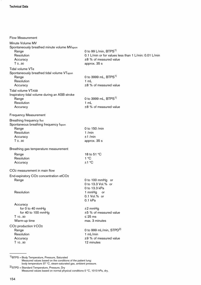
Flow Measurement
Minute Volume MVSpontaneously breathed minute volume MVspon
Range 0 to 99 L/min, BTPS1)
Resolution 0.1 L/min or for values less than 1 L/min: 0.01 L/minAccuracy ±8 % of measured valueT 0...90 approx. 35 s
Tidal volume VTeSpontaneously breathed tidal volume VTspon
Range 0 to 3999 mL, BTPS1)
Resolution 1 mLAccuracy ±8 % of measured value
Tidal volume VTASB
Inspiratory tidal volume during an ASB strokeRange 0 to 3999 mL, BTPS1)
Resolution 1 mLAccuracy ±8 % of measured value
Frequency Measurement
Breathing frequency ftot
Spontaneous breathing frequency fspon
Range 0 to 150 /minResolution 1 /minAccuracy ±1 /minT 0...90 approx. 35 s
Breathing gas temperature measurement
Range 18 to 51 ºCResolution 1 ºCAccuracy ±1 ºC
CO2 measurement in main flow
End-expiratory CO2 concentration etCO2
Range 0 to 100 mmHg or0 to 13.3 Vol.% or0 to 13.3 kPa
Resolution 1 mmHg or0.1 Vol.% or0.1 kPa
Accuracyfor 0 to 40 mmHg ±2 mmHgfor 40 to 100 mmHg ±5 % of measured value
T 10...90 ≤ 25 msWarm-up time max. 3 minutes
CO2 production *CO2
Range 0 to 999 mL/min, STPD2)
Resolution 1 mL/minAccuracy ±9 % of measured valueT 10...90 12 minutes
––––––––––1)BTPS = Body Temperature, Pressure, Saturated
Measured values based on the conditions of the patient lung:body temperature 37 °C, steam-saturated gas, ambient pressure.
2)STPD = Standard Temperature, Pressure, DryMeasured values based on normal physical conditions 0 °C, 1013 hPa, dry.
Technical Data
154

Serial dead space VdsRange 0 to 999 mL, BTPSResolution 0.1 mLAccuracy ±10 % of measured value or ±10 mL,
whichever is greater
Dead space ventilation Vds/VT
Range 0 to 99 %Resolution 1 %Accuracy ±10 % of measured value
Computed value displays
Compliance CRange 0.7 to 200 mL/mbarResolution
Range 0.7 to 99.9 mL/mbar 0.1 mL/mbarRange 100 to 200 mL/mbar 1 mL/mbar
Accuracy ±20 % of measured value*
Resistance RRange 3 to 200 mbar/L/sResolution
Range 3 to 99.9 mL/mbar 0.1 mbar/L/sRange 100 to 200 mL/mbar 1 mbar/L/s
Accuracy ±20 % of measured value**
Leakage minute volume MVleak
Range 0 to 99 L/min, BTPSResolution 0.1 L/min or for values less than 0.1 L/min: 0.01 L/minAccuracy ± 18 % of measured valueT 0...90 approx. 35 s
Rapid Shallow Breathing RSBRange 0 to 9999 1/(min x L)Resolution 1/(min x L)Accuracy see measurement of VT and f
Negative Inspiratory Force NIFRange –45 to 0 mbarResolution 1 mbarAccuracy ± 2 mbar
Curve displaysAirway pressure Paw (t) –10 to 100 mbar
Flow Flow (t) –150 to 180 L/min
Volume V (t) 0 to 2000 mL
Exp. CO2 concentration FCO2 0 to 100 mmHg or 0 to 13 kPa or0 to 13 Vol.%
* C-values may be considerably falsified as spontaneous breathing increases; compliance with the measuring accuracy therefore cannot be guaranteed for spontaneous breathing.
** R-values may be considerably falsified as spontaneous breathing increases; compliance with the measuring accuracy therefore cannot be guaranteed for spontaneous breathing.
155
Technical Data

Monitoring
Expiratory minute volume MVUpper alarm limit alarm when MV exceeds the upper alarm limit.Setting range 41 to 0.1 L/min, in 0.1 L/min steps
Lower alarm limit alarm when MV falls below the lower alarm limit.Setting range 0.01 to 40 L/min, in 0.1 L/min steps
Airway pressure Paw Upper alarm limit alarm if the "Paw high" value is exceeded.Setting range 10 to 100 mbar
Lower alarm limit alarm if the value "PEEP +5 mbar" (coupled with the PEEP set value) is not exceeded for at least 96 ms in 2 successive ventilationstrokes.
Insp. O2 concentration FiO2
Upper alarm limit alarm if FiO2 exceeds the upper alarm limit for at least 20 seconds.Lower alarm limit alarm if FiO2 falls below the lower alarm limit for at least 20 seconds.Range both alarm limits are automatically allocated to the set value:
under 60 Vol.% with ±4 Vol.%over 60 Vol.% with ±6 Vol.%
Endexspiratory CO2-concentration etCO2
Upper alarm limit alarm if the upper alarm limit has been exceeded Setting range 0 to 100 mmHg
or0 to 15 kPa
Lower alarm limit alarm if the lower alarm limit fell below Setting range 0 to 99 mmHg
or0 to 14 kPa
Insp. breathing gas temperatureUpper alarm limit alarm when temperature reaches 40 ºC.
(Evita 4 can also be used without temperature sensor if thesensor is not connected on switching on).
Tachypnoea monitoringAlarm during spontaneous breathing, when the spontaneous breathing
frequency has been exceeded.Setting range 5 to 120/min
Volume monitoringLower alarm limit alarm if the set tidal volume VT (coupled with the set value VT) has not
been supplied.
Upper alarm limit alarm if the applied tidal volume exceeds the value of the alarm limit,inspiration is interrupted and the expiration valve is opened.
Setting range 21 to 4000 mL
Apnoea alarm timeAlarm if no breathing activity is detectedSetting range 5 to 60 s, adjustable in 1 second steps.
Technical Data
156

Operating data Mains power connection 100 V to 240 V
50/60 Hz
Current at 230 V max. 1.3 A at 100 V max. 3.2 A
Power consumption typically approx. 125 W
Machine fuses Range 100 V to 240 V F 5 H 250 V IEC 127-2 (2x)
Protection class Machine Class I
CO2 sensor (sensor connected) Type BF mTemperature sensor AWT 01 Type BF m(sensor connected)
Gas supply O2 gauge pressure 3 bar –10 % to 5.5 bar +10 %
at 60 L/min (peak flow 200 L/min) O2 connection thread M 12 x 1, female
air gauge pressure 3 bar –10 % to 5.5 bar +10 %at 60 L/min (peak flow 200 L/min)
air connection thread M 20 x 1.5, maleThe gases must be dry and free from oil and dust.
Gas consumption of control system Medical air or O2 approx. 3.5 L/minOutput for pneumatic Medical air or O2
medicament nebuliser max. 2 barmax. 10 L/min
Automatic gas switch-over if one gas fails (inlet pressure <1.5 bar), the device switches to the other gas.
Sound pressure level max. 47 dB (A) (for free-field measurement over a reflecting surface)
Dimensions (W x H x D) Basic machine 530 x 290 x 450 mm Machine with trolley 580 x 1335 x 660 mm
Weight Basic machine approx. 27 kg Basic machine with trolley incl. cabinet 8H approx. 69 kg
Machine outputs
Digital output Output and reception via an RS 232 C interface
COM 1 LUST protocolBaudrate: 1200, 2400, 4800, 9600, 19200 baudData bits: 7Parity: evenStop bits: 1
MEDIBUS protocolBaudrate: 1200, 2400, 4800, 9600, 19200 baudData bits: 8Partiy: even, odd, no
157
Technical Data

Stop bits: 1 or 2 (19200 baud are required for transmission of high-speed data,e.g. for flow curve)
Printer protocol HP Deskjet, series 500Baudrate: 1200, 2400, 9600, 19200 baudData bits: 8Parity: noStop bits: 1
Cable length: Up to 15 m
Load impedance: 3000 to 7000 ohm
Signal level (at load impedance 3000 to 7000 ohm)Low Between 3 and 15 VHigh Between –3 and –15 V
Electrical isolation Port COM 1 is electrically isolated from the machine electronics.The test voltage for the electrical isolation equals 1500 V.
Pin assignment Pin 2 RxDPin 3 TxDPin 5 GNDConnector housing Machine housing
Digital output Output for independent lung ventilation (ILV)
Digital output (optional) for output and reception via two RS 232 C interfaces
Digital output (optional) for output and reception via a CAN interface
Analogue output (optional) for output of analog data
Electromagnetic compatibility (EMC) Tested in accordance with EN 60601-1-2(conforming to European Directive 89/336/EEC)
Classification II bas per EC Directive 93/42/EECAnnex IX
UMDNS-Code 17-429Universal Medical DeviceNomenclature System – Nomenclature for medical products
Materials used
Technical Data
158
Part Appearance Material
Ventilation hose milky, transparent silicone rubber
Water traps yellow, transparent polysulphone
Y-piecewith connector for temperature measurement
yellow, transparent
milky, transparent
polysulphone
silicone rubber
Expiration valvehousing, closure
white polyamide
Diaphragm whitish and grey silicone rubber and aluminium
CO2 cuvette yellow, transparent polysulphone with glass windows
Temperature sensor / cable milky / green or blue silicone rubber
CO2 sensor / cable grey / grey polyurethane
Contents
Ventilation Modes................................................................................. 160Volume-controlled ventilation with PLV and AutoFlow ........................... 160Classic volume constant mandatory ventilation stroke............................. 160Manual pressure limiting with Pmax ....................................................... 160AutoFlow ............................................................................................. 161Start-up procedure with AutoFlow ........................................................162Sigh....................................................................................................... 163SIMV..................................................................................................... 164ASB.......................................................................................................165BIPAP....................................................................................................166BIPAPAssist............................................................................................ 167APRV.....................................................................................................168MMV......................................................................................................168Flow measurement.................................................................................170Compensation of the effect of hose system compliance..........................170Conversion according to ambient conditions...........................................170Automatic leakage compensation........................................................... 172Weaning parameters.............................................................................. 174Occlusion pressure P 0.1.......................................................................174Rapid Shallow Breathing RSB................................................................175Negative Inspiratory Force NIF............................................................... 175Intrinsic PEEP........................................................................................ 176Insp. O2 concentration during medicament nebulisation..........................177
Abbreviations........................................................................................ 178Symbols................................................................................................ 181
Bibliography..........................................................................................182
Parts List............................................................................................... 183
Order List.............................................................................................. 185
What was new in Evita 4 software 2.n.................................................. 187
What was new in Evita 4 software 3.n.................................................. 188
Index..................................................................................................... 189
159
DescriptionContents
Description

160
DescriptionVentilation Modes
Ventilation Modes
Volume-controlled ventilation with PLV and AutoFlow
AutoFlow is a new additional function that regulatesinspiratory flow during the mandatory ventilation stroke inthe constant-volume ventilation modes IPPV, SIMV andMMV. To explain the improvement achieved by thisfunction, the conventional methods are explained first:
Classic volume constant mandatory ventilation stroke
In mandatory ventilation strokes without AutoFlow , the»Insp.Flow« parameter restricts the inspiration flow. If theinspiration flow is so high that the set tidal volume VT isattained before the inspiration time Tinsp has fullyelapsed, the inspiration valve closes, and the breathinggas supply stops. The expiration valve remains closeduntil the end of the inspiration time Tinsp. This phase, theinspiratory pause, can be identified in the curve Paw (t)as the plateau Pplat.
This type of mandatory ventilation stroke, which fortechnical reasons is found in the same form in almost allintensive care ventilators, has two serious drawbacks:
– If the lungs are extremely non-homogeneous, thepressure peaks can lead to the overdistension ofspecific lung areas, and
– the limited inspiration flow and closed inspiration andexpiration valves during the inspiratory pause cancause the patient to "fight" the machine, unless thepattern of ventilation is regularly adapted to the needsof the spontaneously breathing patient.
Manual pressure limiting with Pmax
Evita 4 can prevent pressure peaks, while maintaining theset tidal volume VT, by means of the pressure limit Pmax.The tidal volume VT remains constant as long as apressure plateau Pplat is still detectable and the flowcurve shows a brief zero flow between inspiration andexpiration.
Evita 4 performs this function by reducing the Insp. Flowon reaching the set Pmax value. If the tidal volume VT canno longer be attained with the selected pressure Pmax,due to reduced compliance, the alarm "Volume notconstant" is automatically generated.Manual pressure limiting can be performed with all Evitamodels.
Paw
Flow
Tinsp Te
Pplat
Insp.pause
Pmax(configu-rable)
PEEP
1f
Insp. flow
t
t
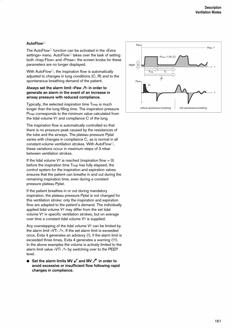
AutoFlow
The AutoFlow function can be activated in the »Extrasettings« menu. AutoFlow takes over the task of settingboth »Insp.Flow« and »Pmax«: the screen knobs for theseparameters are no longer displayed.
With AutoFlow , the inspiration flow is automaticallyadjusted to changes in lung conditions (C, R) and to thespontaneous breathing demand of the patient.
Always set the alarm limit »Paw WWWW« in order togenerate an alarm in the event of an increase inairway pressure with reduced compliance.
Typically, the selected inspiration time Tinsp is muchlonger than the lung filling time. The inspiration pressurePinsp corresponds to the minimum value calculated fromthe tidal volume VT and compliance C of the lung.
The inspiration flow is automatically controlled so thatthere is no pressure peak caused by the resistances ofthe tube and the airways. The plateau pressure Pplatvaries with changes in compliance C, as is normal in allconstant-volume ventilation strokes. With AutoFlow ,these variations occur in maximum steps of 3 mbarbetween ventilation strokes.
If the tidal volume VT is reached (inspiration flow = 0)before the inspiration time Tinsp has fully elapsed, thecontrol system for the inspiration and expiration valvesensures that the patient can breathe in and out during theremaining inspiration time, even during a constantpressure plateau Pplat.
If the patient breathes in or out during mandatoryinspiration, the plateau pressure Pplat is not changed forthis ventilation stroke: only the inspiration and expirationflow are adapted to the patient's demand. The individuallyapplied tidal volume VT may differ from the set tidalvolume VT in specific ventilation strokes, but on averageover time a constant tidal volume VT is supplied.
Any overstepping of the tidal volume VT can be limited bythe alarm limit »VTi W«. If the set alarm limit is exceededonce, Evita 4 generates an advisory (!); if the alarm limit isexceeded three times, Evita 4 generates a warning (!!!). In the above examples the volume is actively limited to thealarm limit value »VTi W« by switching over to the PEEPlevel.
● Set the alarm limits MV <<<< and MV >>>> in order toavoid excessive or insufficient flow following rapidchanges in compliance.
161
DescriptionVentilation Modes
PawPaw >
Flow
ohne Spontanatmung mit Spontanatmung
VT
PEEP
Tinsp Te
1f
t
t
Pinsp = f (VT,C)
without spontaneous breathing with spontaneous breathing
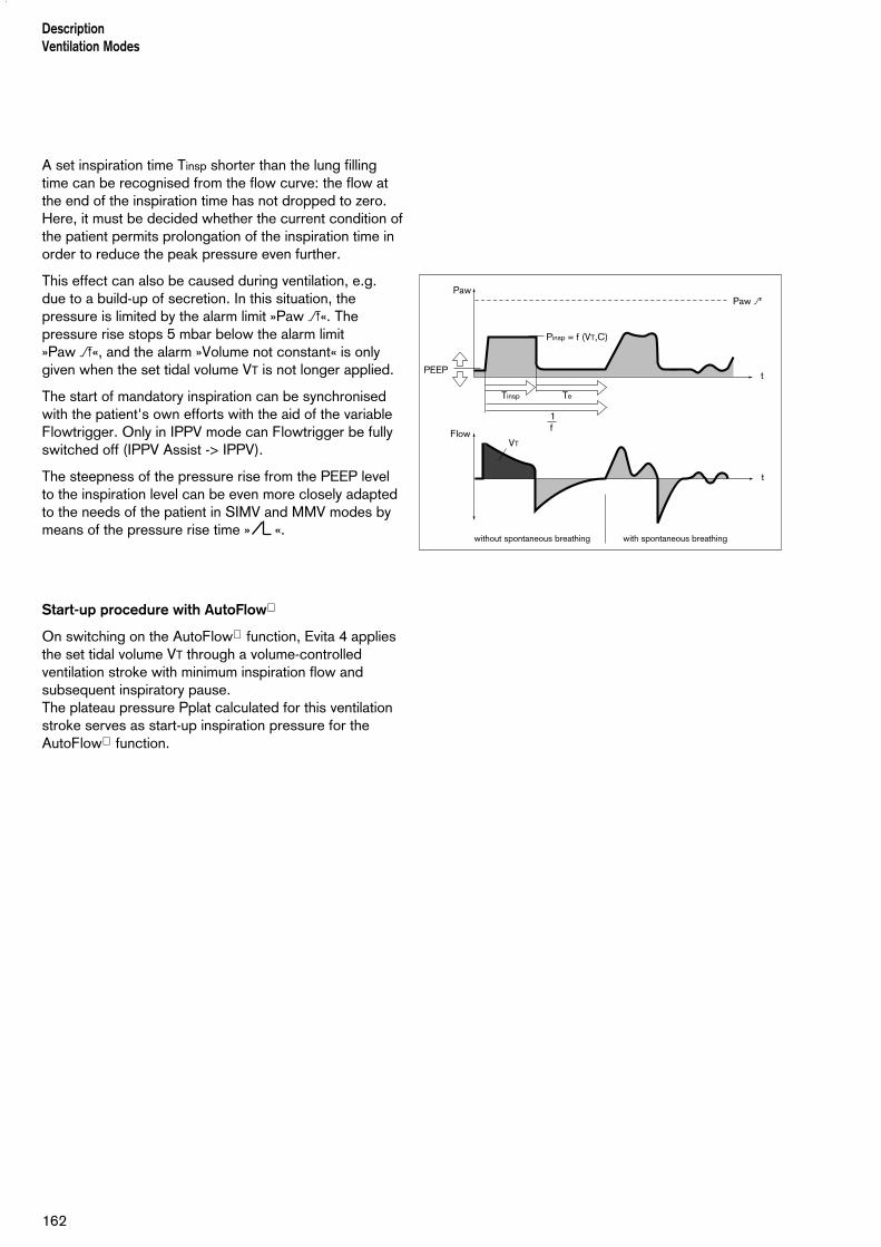
A set inspiration time Tinsp shorter than the lung fillingtime can be recognised from the flow curve: the flow atthe end of the inspiration time has not dropped to zero.Here, it must be decided whether the current condition ofthe patient permits prolongation of the inspiration time inorder to reduce the peak pressure even further.
This effect can also be caused during ventilation, e.g.due to a build-up of secretion. In this situation, thepressure is limited by the alarm limit »Paw W«. Thepressure rise stops 5 mbar below the alarm limit »Paw W«, and the alarm »Volume not constant« is onlygiven when the set tidal volume VT is not longer applied.
The start of mandatory inspiration can be synchronisedwith the patient's own efforts with the aid of the variableFlowtrigger. Only in IPPV mode can Flowtrigger be fullyswitched off (IPPV Assist -> IPPV).
The steepness of the pressure rise from the PEEP levelto the inspiration level can be even more closely adaptedto the needs of the patient in SIMV and MMV modes bymeans of the pressure rise time » «.
Start-up procedure with AutoFlow
On switching on the AutoFlow function, Evita 4 appliesthe set tidal volume VT through a volume-controlledventilation stroke with minimum inspiration flow andsubsequent inspiratory pause.The plateau pressure Pplat calculated for this ventilationstroke serves as start-up inspiration pressure for theAutoFlow function.
162
DescriptionVentilation Modes
PawPaw >
Flow
ohne Spontanatmung mit Spontanatmung
VT
PEEP
Tinsp Te
1f
t
t
Pinsp = f (VT,C)
without spontaneous breathing with spontaneous breathing

163
DescriptionVentilation Modes
Sigh
"Sigh« is operative in the form of intermittent PEEP inIPPV, IPPV Assist and ILV.
The purpose of expiratory sigh during ventilation is toopen collapsed areas of the lung, or to keep open "slow"areas of the lung.
Since atelectatic alveoli have a longer time constant –also caused by obstructed bronchioles – increasedairway pressure maintained over a longer period isrequired to open them.
In many cases, the sigh function is achieved byincreasing the ventilation stroke; however, due to theshort time available, the filling of the »slow« alveoli is onlymarginally improved.
In Evita 4, the sigh operates during expiration with anintermittent PEEP for two ventilation strokes every 3 minutes.
The average airway pressure is higher, and a longer fillingtime is normally available.
To avoid overinflation of the lung, the pressure peaksduring the sigh phase can be limited by pressurelimitation, Pmax, without impairing the sigh function.
During the sigh phase, the "Volume not constant" alarmis disabled.
PawSigh phase
Pmax
interm.PEEP
PEEP
t

DescriptionVentilation Modes
164
SIMV Synchronised Intermittent Mandatory Ventilation
Combination of machine ventilation and spontaneousbreathing.
SIMV enables the patient to breathe spontaneously inregular prescribed cycles, with the mechanical mandatoryventilation strokes providing a minimum ventilation duringthe remaining cycles. The minimum ventilation is controlled by the two setvalues tidal volume (VT) and ventilation frequency (f) andis determined from the product of VT x f.
The ventilation pattern results from the set values VT,Insp. Flow, frequency f and inspiration time Tinsp.To prevent the mandatory ventilation stroke being appliedduring spontaneous expiration, the Flowtrigger of themachine ensures that the ventilation stroke is triggered insynchrony with the patient's spontaneous inspiratoryeffort within a "trigger window".
The "trigger window" is 5 seconds long in adult modeand 1.5 seconds long in paediatric mode. If the expirationtimes are less than 5 seconds or 1.5 seconds, the"trigger window" covers the entire expiration time.
Since the synchronisation of the mandatory ventilationstroke reduces the effective SIMV time, which wouldresult in an undesirable increase in effective IMVfrequency, Evita 4 prolongs the subsequent breathingtime by the missing time difference ∆T – thus preventingan increase in SIMV frequency. The frequency para-meter f remains constant. This parameter, in combinationwith the tidal volume VT, sets the minimum ventilation. If the inspiratory volume of the patient is considerable atthe beginning of the "trigger window", the machinereduces the subsequent mandatory ventilation stroke byshortening the time for the inspiratory flow phase and theinspiration time. In this way, the tidal volume VT remainsconstant, and overinflation of the lungs is avoided.
During the spontaneous breathing phases, the patientcan be assisted with pressure by ASB pressure support.
In the further weaning process, the frequency f on theventilation unit is further reduced, thereby prolonging thespontaneous breathing time, until finally the requiredminute volume is entirely covered by spontaneousbreathing.
Paw
PEEP
t
spontaneous breathing time
spontaneous breathing time + T
set IMV time set IMV time
triggerwindow
spontaneous breathing
mandatory ventilation
synchronised mandatory stroke
Tinsp
f1
f1

165
DescriptionVentilation Modes
ASB Assisted Spontaneous Breathing
Pressure support for insufficient spontaneous breathing.
The function of the machine in assisting insufficientspontaneous breathing is similar to that of the anaesthe-tist who manually assists and monitors the patient'sspontaneous breathing by feeling the breathing bag.
The machine takes over part of the inhalation function,with the patient maintaining control of spontaneousbreathing.
The CPAP system supplies the spontaneously breathingpatient with the breathing gas, even if the inspirationeffort is weak.
The pressure support of the ASB system is started:
– when the spontaneous inspiration flow reaches theset value of the Flowtrigger, or at the latest
– when the spontaneous inspired volume exceeds 25 mL (12 mL in paediatric mode).
The machine then produces an increase in pressure upto the preselected ASB pressure PASB, which isadjustable to the breathing requirement of the patient.
The time for this pressure increase is adjustable from 64 milliseconds to 2 seconds.
With a rapid increase in pressure Evita 4 supports the insufficient spontaneous breathing of the patient with a high peak flow.
With a slow increase in pressure Evita 4 begins gently with regular inspiratory flow. Thepatient has to take over more breathing effort, and tone ofbreathing muscles improves.
With the patient adjusted pressure increase and thepresent ASB level, the patient's own breathing activitydefines the required inspiration flow, which can rise in 8 ms to 2 L/s.
ASB is terminated:
– when the inspiration flow returns to zero during phase I, i.e. when the patient exhales or fights theventilator, or
– when the inspiration flow in phase II falls below acertain ratio of the maximum value previously supplied:for adult ventilation: 25 % Insp.Flowfor paediatric ventilation: 25 % Insp.Flowor
– at the latest after 4 seconds (1.5 seconds inpaediatric ventilation) if the two other criteria have notcome into operation.If this 4-second criteria occurs three times insuccession, Evita 4 sounds an alarm and warns of apossible leak in the ventilation system.
PhaseI II
Prescribed ideal airway pressure
Paw
Insp.Flow
t
t
PASB
CPAP
Start of inspiration
max. 4 s
End of inspiration
25 % Insp.Flow for adults 6 % Insp.Flow for paediatrics25 % Insp.Flow for adults25 % Insp.Flow for paediatrics
DescriptionVentilation Modes
166
BIPAP Biphasic Positive Airway Pressure
The BIPAP ventilation mode is a pressure/time-cycledventilation mode in which the patient can always breathespontaneously. BIPAP is therefore often described as atime-cycled alternation between two CPAP levels.*
The time-cycled change of pressure gives controlledventilation, which corresponds to pressure-controlledventilation PCV. However, the constant option of spon-taneous breathing allows the transition from controlledbreathing to independent spontaneous breathing to takeplace smoothly via the weaning phase, without requiringany change the ventilation mode. To adapt easily to thepatient's spontaneous breathing pattern, the change-overfrom expiratory pressure level to inspiratory pressurelevel, and also the change-over from inspiratory pressurelevel to expiratory pressure level, are synchronised withthe patient's spontaneous breathing.
The frequency of the change-over is kept constant, evenwhen synchronisation occurs via a "trigger window" withfixed time constant.
The "trigger window" is 5 seconds long in adult modeand 1.5 seconds long in paediatric mode. For expirationtimes shorter than 5 seconds or 1.5 seconds, the "trigger window" covers the entire expiration time.At Pinsp level, the "trigger window" is 1/4 · Tinsp secondslong.
As recent clinical research** has shown, this smoothadaptation to the patient's spontaneous breathingrequires less sedation, so that the patient returns tospontaneous breathing more rapidly.
As in all pressure-controlled ventilation modes, thepatient is not prescribed a fixed tidal volume (VT). The tidal volume results principally from the pressuredifference between the settings for PEEP and Pinsp.
Changes in lung compliance and airways, as well asactive breathing by the patient can lead to changes intidal volume. This is a desired effect in this ventilationmode.
With the knowledge that the tidal volume, and thereforethe minute volume, are not constant, the alarm limits forminute volume must be adjusted with care.
The display of the expiratory measured tidal volume VTe
must be used to set the required difference between thetwo pressure levels. Any increase in differential will causean increased BIPAP ventilation stroke.
_____________
* Bibliography (3), (4), (7), (11), (12), page 182** Bibliography (8), page 182

As with SIMV, the time pattern is set using the basicsetting parameters of frequency f and Tinsp. The resulting inspiration and expiration times are cal-culated by Evita 4 and displayed in the lower half of thescreen below the curve setting. The lower pressure levelis set with the PEEP parameter, while the upper level isset with Pinsp.When switching over from IPPV to BIPAP mode, only thePinsp setting needs to be changed.
The steepness of the increase from the lower pressurelevel to the upper pressure level is controlled by thesetting . The effective time for the increase in pressurecannot become greater than the set inspiratory time Tinsp.This precaution ensures that the upper pressure levelPinsp is reached safely during inspiration. The transitionfrom controlled ventilation via the weaning phase to fullyspontaneous breathing is achieved by a gradual reduc-tion of inspiratory pressure Pinsp and/or frequency f.
BIPAPAssist
Biphasic Positive Airway Pressure Assisted
Pressure-controlled, assisted ventilation
The inspiratory strokes are the same as for BIPAP,except that the change from Pinsp to PEEP is notsynchronised with expiration by the patient.The duration of Pinsp depends on Tinsp.The patient can breathe spontaneously throughout theventilation process.
Every detected spontaneous breathing activity by thepatient triggers a synchronised inspiration stroke.
A non-synchronised inspiratory stroke is triggered by themachine at the latest upon expiry of the inspiration timedefined by »f« and »Tinsp«.
For all patients, from those unable to breathespontaneously to those breathing spontaneously beforebeing weaned off the ventilator.
167
DescriptionVentilation Modes
Paw
Flow
Pinsp
PEEP
slowrise time
fastrise time
t
t
TinspTrigger window for synchronisation
f1
without spontaneous breathing
with spontaneous breathing
Paw
PEEP
t
Spontaneous breathing time
Trigger window
Spontaneous breathing
Mandatory BIPAP stroke
Synchronised BIPAP stroke
Tinsp
f1
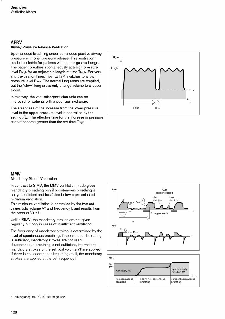
APRVAirway Pressure Release Ventilation
Spontaneous breathing under continuous positive airwaypressure with brief pressure release. This ventilationmode is suitable for patients with a poor gas exchange.The patient breathes spontaneously at a high pressurelevel Phigh for an adjustable length of time Thigh. For veryshort expiration times Tlow, Evita 4 switches to a lowpressure level Plow. The normal lung areas are emptied,but the "slow" lung areas only change volume to a lesserextent.*
In this way, the ventilation/perfusion ratio can beimproved for patients with a poor gas exchange.
The steepness of the increase from the lower pressurelevel to the upper pressure level is controlled by thesetting . The effective time for the increase in pressurecannot become greater than the set time Thigh.
MMVMandatory Minute Ventilation
In contrast to SIMV, the MMV ventilation mode givesmandatory breathing only if spontaneous breathing is not yet sufficient and has fallen below a pre-selectedminimum ventilation. This minimum ventilation is controlled by the two setvalues tidal volume VT and frequency f, and results fromthe product VT x f.
Unlike SIMV, the mandatory strokes are not givenregularly but only in cases of insufficient ventilation.
The frequency of mandatory strokes is determined by thelevel of spontaneous breathing: if spontaneous breathingis sufficient, mandatory strokes are not used.If spontaneous breathing is not sufficient, intermittentmandatory strokes of the set tidal volume VT are applied.If there is no spontaneous breathing at all, the mandatorystrokes are applied at the set frequency f.
____________
* Bibliography (6), (7), (8), (9), page 182
DescriptionVentilation Modes
168
Thigh Tlow
Phigh
Plow
t
Paw
Paw
Flow
Tinsp
PmaxPEEP
shortrise time
longrise time
trigger phase
VT
Insp. Flow
t
t
1f
ASBpressure support
MV
sufficient spontaneous breathing
spontaneously breathed MV
set MV
mandatory MV
beginning spontaneous breathing
no spontaneous breathing
t

Evita 4 continuously balances the difference betweenspontaneous breathing and the set minimum ventilation.As soon as the balance becomes negative, becausespontaneous breathing is no longer sufficient, Evita 4applies a mandatory ventilation stroke at the set tidalvolume VT, so that the balance is again positive.
Experience shows, patients breathe very irregularly.Phases of weak breathing alternate with phases of heavybreathing. In order to allow for these individual fluctua-tions, the balancing process also takes account of theextent by which the set minimum ventilation has beenexceeded.This positive allowance is progressively reduced to zeroby Evita 4 within a maximum of 7.5 seconds after apnoea.
In other words, the response time of Evita 4 beforeactivating mandatory ventilation is automatically adaptedto the preceding cycle of spontaneous breathing:
If this spontaneous breathing was close to the minimumventilation, the machine responds rapidly within the IMVtime. By contrast, if the patient's spontaneous breathingwas much higher than the set minimum ventilation, Evita 4 tolerates a longer breathing pause. In extremecases of sudden apnoea after a phase of heavybreathing, the response time will be 7.5 seconds plus the trigger time, with a minimum of 1 IMV cycle time.
Response times longer than 15 seconds may only occurif the minimum ventilation with a low IMV frequency f isset to correspondingly low values.
In this case, Evita 4 triggers an apnoea alarm that iscancelled again as soon as the mandatory ventilationstrokes have been applied. If the IMV is set to a longerperiod than the TApnoea > alarm limit, and if there is nospontaneous breathing between the mandatory ventilationstrokes, the apnoea alarm will be regularly triggered. Example: f = 3/min = IMV time = 20 seconds
TApnoea > = 15 secondsThis system is designed to prevent mandatory ventilationbeing prematurely triggered in the event of irregularspontaneous breathing, whilst at the same time giving an alarm for any long period of low ventilation.
169
DescriptionVentilation Modes
Paw
Flow
Tinsp
PmaxPEEP
shortrise time
longrise time
trigger phase
VT
Insp. Flow
t
t
1f
ASBpressure support
MV
sufficient spontaneous breathing
spontaneously breathed MV
set MV
mandatory MV
beginning spontaneous breathing
no spontaneous breathing
t

Flow measurement
Regardless of whether ventilation is volume-controlled orpressure-controlled, positive pressures are generated inboth the breathing system and patient lung during theinspiration phase. Depending on the ratio of lung compliance to hosesystem compliance, the volume delivered by the ventilatoris distributed to the patient's lung and to the hose systeminstalled between the ventilator and patient.Deviations in the measured expiration flow and derivedvalues, such as the minute volume and breath volume,are low for adult patients, due to their relatively high lungcompliance in relation to the much lower compliance ofthe ventilation hoses.
However, since only the volume attained and surrenderedby the lung is relevant to the efficiency of ventilation, andsince higher differences are possible during paediatricventilation, Evita 4 provides basic compensation for hosecompliance during ventilation.
Compensation of the effect of hose systemcompliance
During the device check before ventilation, Evita 4determines the compliance of the ventilation hoses, andthen, during ventilation, compensates for the effect ofcompliance on volumetric flow measurement.
Depending on the airway pressure, Evita 4 increases thetidal volume by the amount that remains in the ventilationhoses.
In addition to hose system compliance, flow/volumemeasurement is influenced by the environmental factorsof temperature and humidity and by leaks in the hosesystem.Evita 4 takes these factors into account and corrects thesettings and measured values accordingly.
Conversion according to ambient conditions
The volume occupied by a gas depends on the ambientconditions of temperature, pressure and humidity.In lung physiology, the minute volume and tidal volumeare related to the ambient conditions in the lung:37 °C body temperature, pressure in the lung, 100 % relative humidity.
170
DescriptionVentilation Modes

The flow and volume values measured under theseconditions are marked with BTPS*. On the other hand,medical gases from cylinders or from the central supplyare dry (approx. 0 % r.h.) and are delivered by theventilator at 20 °C. The flow and volume valuesmeasured under these conditions are marked NTPD**.The difference between measured values under NTPDand BTPS conditions is typically approx. 12 %.
Example: a tidal volume of 500 mL NTPD is increased to564 mL BTPS by heating to 37 °C and humidifying to100 % r.h..Evita 4 delivers the tidal volume after conversion, so thatthe set tidal volume is effective in the lung under BTPSconditions.
____________
* BTPS = Body Temperature, Pressure, Saturated.
** NTPD = Normal Temperature Pressure Dry.
171
DescriptionVentilation Modes

Automatic leakage compensation
Evita 4 determines the difference between the deliveredflow on the inspiration side and the measured flow on theexpiration side.This difference provides a measure of the amount ofleakage and is displayed by Evita 4 as the leakage minutevolume MVleak. Evita 4 can compensate for this leakagein volume controlled ventilation.
Example:Tidal volume setting VT = 500 mL, 10 % leakage in tube.
Leakage compensation OffEvita 4 delivers 500 mL. This is indicated as theinspiratory tidal volume VTi. 50 mL escape as leakageduring inspiration, and 450 mL reach the lung. 450 mLare expired, and 45 mL again escape as leakage.A tidal volume of 405 mL is measured on the expirationside and indicated as VTe.With a ventilation rate of 10 strokes per minute, a minutevolume of 5.0 L/min is delivered on the inspiration sideand a minute volume of 4.05 L/min is measured on theexpiration side. The lung is ventilated with an MV of 4.5 L/min.Without leakage compensation, the set VT determinesthe volume delivered by Evita 4.
Leakage compensation On With automatic leakage compensation, Evita 4 delivers550 mL on the basis of the measured leakage minutevolume, instead of the 500 mL set. 500 mL enter the lung and the displayed inspiratory tidal volume VT is 500 mL.The volume of 450 mL measured on the expiration side is displayed without compensation, even whenleakage compensation is activated. The minute volumemeasured on the expiration side is 4.5 L/min and is alsouncompensated.If this were not so, the alarm for a low minute volumecould be inhibited by the expiratory leakagecompensation. Evita 4 must always emit an alarm if the minute volume is too low.With leakage compensation, the set VT determinesthe volume to be delivered to the patient.
This example has been simplified:In fact, the calculated leakage correction takes intoaccount the pressures in the hose system. A higherpercentage volume is lost on the inspiration side than onthe expiration side because the pressure duringinspiration is higher. The displayed leakage minutevolume MVleak is based on the mean pressure Pmean.
172
DescriptionVentilation Modes
The leakage minute volume MVleak also takes theinspiratory leaks into account. The sum of the minutevolume MV + the leakage minute volume MVleak isconsequently greater than the inspiratory minute volumedelivered to the patient.
Unlimited volume compensation is inappropriate. Evita 4 compensates for losses of up to 100 % of the set tidal volume VT.Due to technical tolerances, a small leakage minutevolume may be displayed even if the hose system isleakproof.
173
DescriptionVentilation Modes

Weaning parameters
P 0.1, RSB, NIF:
A number of criteria must be taken into account by thedoctor when deciding whether or not a patient is ready to be weaned off the ventilator. In addition to the resultsof examinations and laboratory analyses, ventilationparameters can also be used to judge whether thepatient can be weaned successfully.
The following weaning parameters are calculated by Evita 4:
– Occlusion pressure P 0.1
– Rapid Shallow Breathing RSB
– Negative Inspiratory Force NIF
Occlusion pressure P 0.1
Breathing drive can be measured at the start of inspira-tion by measuring the mouth pressure during a short-termocclusion: within 100 ms, the pressure is not influencedby physiological compensation reaction (e.g. reflectedbreathing stop or increased breathing drive). Thispressure is always dependent on the muscle strength ofthe diaphragm. Therefore, the negative mouth pressure P 0.1 after 0.1 seconds is a direct measure of neuro-muscular breathing drive*.
For patients with healthy lungs and regular breathing, P 0.1 will be about –3 to –4 mbar. A higher P 0.1signifies a high breathing drive which can only bemaintained for a limited period. P 0.1 values about –6 mbar, e.g. for a COPD** patient, indicate impendingexhaustion (RMF – respiratory muscle fatigue).
When weaning COPD patients off the Ventilator,measurement of P 0.1 can define the weaning point.
To measure P 0.1, Evita 4 keeps the inspiratory valveclosed after one expiration and measures the airwaypressure produced by the inspiratory effort during 100 ms (P1).
The 100 ms time interval starts when a negative pressureof –0.5 mbar is measured as a result of the inspiratoryeffort.
A second pressure value (P2) is activated after 100 ms.Simultaneously, the inspiratory valve is opened so thatthe patient can breathe normally again.
The occlusion pressure P 0.1 is the difference betweenthe pressure values P2 – P1.
––––––––––––––––* Bibliography (10), (15), page 182** COPD = Chronic Obstructive Pulmonary Disease
174
DescriptionWeaning parametersOcclusion pressure P 0.1
Paw
CPAP–0,5 mbar
100 ms
P 0.1
P1
P2
t
Insp. valve closed
Insp. valve open
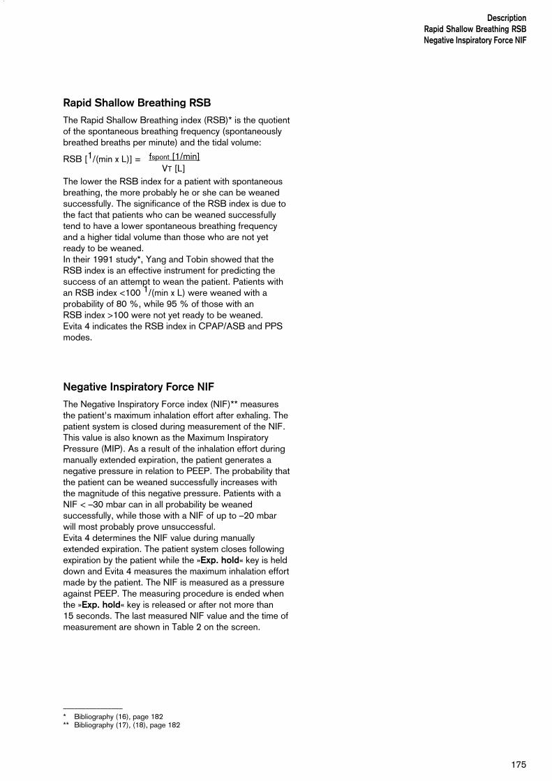
Rapid Shallow Breathing RSB
The Rapid Shallow Breathing index (RSB)* is the quotientof the spontaneous breathing frequency (spontaneouslybreathed breaths per minute) and the tidal volume:
RSB [1/(min x L)] =
The lower the RSB index for a patient with spontaneousbreathing, the more probably he or she can be weanedsuccessfully. The significance of the RSB index is due tothe fact that patients who can be weaned successfullytend to have a lower spontaneous breathing frequencyand a higher tidal volume than those who are not yetready to be weaned. In their 1991 study*, Yang and Tobin showed that theRSB index is an effective instrument for predicting thesuccess of an attempt to wean the patient. Patients withan RSB index <100 1/(min x L) were weaned with aprobability of 80 %, while 95 % of those with an RSB index >100 were not yet ready to be weaned. Evita 4 indicates the RSB index in CPAP/ASB and PPSmodes.
Negative Inspiratory Force NIF
The Negative Inspiratory Force index (NIF)** measuresthe patient's maximum inhalation effort after exhaling. Thepatient system is closed during measurement of the NIF.This value is also known as the Maximum InspiratoryPressure (MIP). As a result of the inhalation effort duringmanually extended expiration, the patient generates anegative pressure in relation to PEEP. The probability thatthe patient can be weaned successfully increases withthe magnitude of this negative pressure. Patients with aNIF < –30 mbar can in all probability be weanedsuccessfully, while those with a NIF of up to –20 mbarwill most probably prove unsuccessful.Evita 4 determines the NIF value during manuallyextended expiration. The patient system closes followingexpiration by the patient while the »Exp. hold« key is helddown and Evita 4 measures the maximum inhalation effortmade by the patient. The NIF is measured as a pressureagainst PEEP. The measuring procedure is ended whenthe »Exp. hold« key is released or after not more than 15 seconds. The last measured NIF value and the time ofmeasurement are shown in Table 2 on the screen.
––––––––––––––––* Bibliography (16), page 182** Bibliography (17), (18), page 182
175
DescriptionRapid Shallow Breathing RSBNegative Inspiratory Force NIF
fspont [1/min] VT [L]

DescriptionIntrinsic PEEP
176
Intrinsic PEEPEvita 4 keeps the inspiratory valve and expiratory valveclosed during measuring time 1, so that it is impossiblefor gas either to flow into the ventilation system frominspiration or to escape from it. During this closed phase,pressure is equalised between the lungs and theventilation system. Evita 4 measures the pressure curve.Measuring phase 1 is ended:
– when there is no further change in the pressure curve but at the earliest after 0.5 seconds.
– at the latest after 3 seconds in adult mode and after1.5 seconds in paediatric mode.
The start value corresponds to PEEP, and the value atthe end of the closed phase is the Intrinsic PEEP.
At the end of measuring time 1, Evita 4 opens theexpiration valve and measures the expiratory flow genera-ted by Intrinsic PEEP during a defined measuring time 2.During this period, the lung is depressurised to PEEP.Measuring phase 2 is ended:
– when the expiration flow has returned to 0but at the earliest after 0.5 seconds.
– at the latest after 7 seconds in adult mode or after 3.5 seconds in paediatric mode.
The integrated flow corresponds to the air volumetrapped in the lungs (Vtrap) by Intrinsic PEEP.
Measuring times of the measuring phase 1 for IntrinsicPEEP:For adult ventilation max. 3 secondsFor paediatric ventilation max. 1.5 seconds
Measuring times of the measuring phase 2 for Vtrap:For adult ventilation max. 7 secondsFor paediatric ventilation max. 3.5 seconds
Paw
t
insp. and exp. valves closed exp. valve opens
t
Flow
PEEP
Vtrap
Intrinsic PEEP
measuringtime 1
measuring time 2
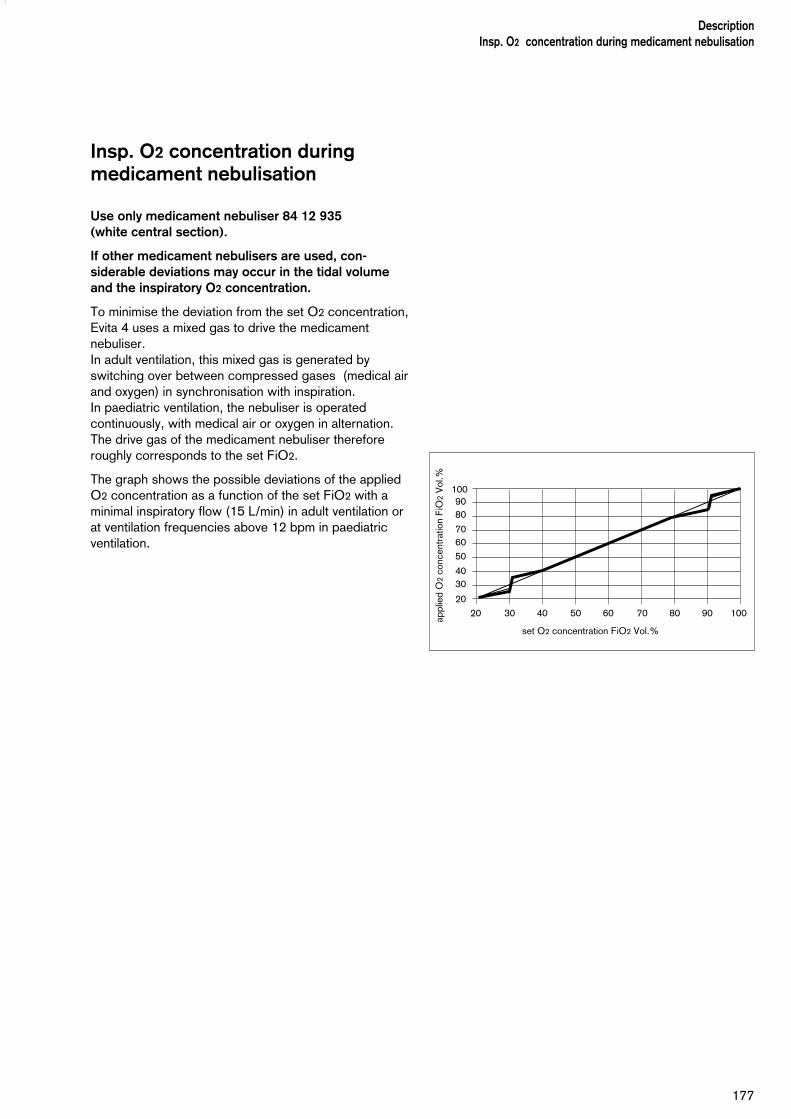
177
DescriptionInsp. O2 concentration during medicament nebulisation
Insp. O2 concentration duringmedicament nebulisation
Use only medicament nebuliser 84 12 935 (white central section).
If other medicament nebulisers are used, con-siderable deviations may occur in the tidal volume and the inspiratory O2 concentration.
To minimise the deviation from the set O2 concentration,Evita 4 uses a mixed gas to drive the medicamentnebuliser.In adult ventilation, this mixed gas is generated byswitching over between compressed gases (medical airand oxygen) in synchronisation with inspiration.In paediatric ventilation, the nebuliser is operatedcontinuously, with medical air or oxygen in alternation.The drive gas of the medicament nebuliser thereforeroughly corresponds to the set FiO2.
The graph shows the possible deviations of the appliedO2 concentration as a function of the set FiO2 with aminimal inspiratory flow (15 L/min) in adult ventilation orat ventilation frequencies above 12 bpm in paediatricventilation.
2020
3040
506070
8090
set O2 concentration FiO2 Vol.%
appl
ied
O2
conc
entr
atio
n F
iO2
Vol
.%
30 40 50 60 70 80 90 100
100
Abbreviations
Abreviation Definition
APRV Airway Pressure Release VentilationSpontaneous breathing at continuous positive airwaypressure with short-term pressure release
ASB Assisted Spontaneous BreathingPressure supported spontaneous breathing
BIPAP BIphasic Positive Airway PressureVentilation mode for spontaneous breathing at continuouspositive airway pressure with two different pressure levels
BIPAPAssist Biphasic Positive Airway Pressure AssistedVentilation mode for assisted ventilation with continuouspositive airway pressure with two different pressure levels
bpm breaths per minute
BTPS Body Temperature, Pressure. SaturatedMeasured values based on the condition of the patient'slungs, with body temperature 37 ºC, steam-saturated gas,atmospheric pressure
C Compliance
CPAP Continuous Positive Airway PressureBreathing with continuous positive pressure in the airways
etCO2 End-expiratory CO2 concentration
FeCO2 Expiratory CO2 concentration
f Frequency
fApnoea Frequency setting for apnoea ventilation
fmand Mandatory mechanical portion of overall breathingfrequency
fspn Spontaneous breathing portion of overall breathingfrequency
Fail to cycle Breathing cycle failure. Machine detects no inspiration
FiO2 Inspiratory O2 concentration
Flow Set value of the maximum inspiratory flow
FlowTrig Set value of the flow trigger threshold
ILV Independent Lung VentilationVentilation with 2 ventilators, 1 for each lung
Int. PEEP Intermittent Positive End-Expiratory Pressure= Sigh
IPPV Intermittent Positive Pressure Ventilation
IPPVAssist Trigger Assist Intermittent Positive Pressure Ventilation
IRV Inversed Ratio VentilationVentilation with inversed inspiration/expiration ratio
DescriptionAbreviations
178

Abreviation Definition
ISO 5369 International standard for mechanical ventilators – "Lung Ventilation"
I:E Ratio of Inspiration to Expiration
body Wt Body weight (kg)
MMV Mandatory Minute Volume Ventilation
MV Minute Volume
MVleak Leakage minute volume
MVspn Spontaneous breathed minute volume
NIF Negative Inspiratory ForceMaximum inhalation effort
O2 Set value for inspiratory oxygen concentration [Vol.%]
P 0.1 100 ms occlusion pressure
PASB Set value of ASB pressure support
Paw Airway pressure
PEEP Positive End-Expiratory Pressure
PEEPi Intrinsic Positive End-Expiratory Pressure
Phigh Set value of the upper pressure level APRV
Pinsp Set value of the upper pressure level in BIPAP
Plow Set value of the lower pressure level in BIPAP
Pmax Set value for pressure limited ventilation
Pmean Mean airway pressure
PLV Pressure Limited Ventilation
Ppeak Peak pressure
Pplat End-inspiratory airway pressure
PS Pressure Support
R Resistance
RSB Rapid Shallow BreathingQuotient of spontaneous breathing frequency and tidal volume
SIMV Synchronized Intermittent Mandatory Ventilation
T Inspiratory breathing gas temperature
TApnoea Apnoea alarm time
Te Expiration time
TGI Tracheale Gas Insuflation
Thigh Time for the upper pressure level in APRV
Tinsp Set value of the inspiratory time
Tlow Time for the lower pressure level in APRV
179
DescriptionAbreviations

Abreviation Definition
*CO2 CO2 production [L/min]
Vds Serial dead space
VT Setting for tidal volume
VTApnoea Setting for tidal volume of apnoea ventilation
VTASB Inspiratory breathing volume during an ASB stroke
VTe Expiratory tidal volume
VTi Inspiratory tidal volume
Vtrap Volume trapped in the lung by intrinsic PEEP, and exhaled during subsequent expiration.
180
DescriptionAbreviations
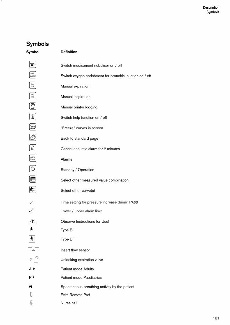
181
DescriptionSymbols
SymbolsSymbol Definition
V Switch medicament nebuliser on / off
Switch oxygen enrichment for bronchial suction on / off
Manual expiration
Manual inspiration
C Manual printer logging
⁄ Switch help function on / off
s "Freeze" curves in screen
Q Back to standard page
G Cancel acoustic alarm for 2 minutes
Alarms
E Standby / Operation
¶ Select other measured value combination
π Select other curve(s)
Time setting for pressure increase during PASB
_ Lower / upper alarm limit
Observe Instructions for Use!
m Type B
m Type BF
Insert flow sensor
Unlocking expiration valve
A m Patient mode Adults
P m Patient mode Paediatrics
⁄ Spontaneous breathing activity by the patient
Evita Remote Pad
Nurse call
AlarmReset
Exp.hold
Insp.hold
O2 ↑↑↑↑suction

Bibliography
(1) Baum, M., Benzer, H., Mutz, N., Pauser, G.,Tonczar, L.: Inversed Ratio Ventilation (IRV) Die Rolle des Atemzeitverhältnisses in der Ventilationbeim ARDS Anaesthesist 29 (1980), 592-596
(2) Geyer, A., Goldschmied, W., Koller, W., Winter, G.:Störung der Gerätefunktion bei Anbringung einesBakterienfilters in den Exspirationsschenkeln desVentilationssystems Anaesthesist 34 (1985), 129-133
(3) Baum, M., Benzer, H., Putensen, Ch., Koller, W.,Putz, G.:Biphasic Positive Airway Pressure (BIPAP) – eineneue Form der augmentierenden VentilationAnaesthesist 38 (1989), 452-458
(4) Luger, Th.J., Putensen, Ch., Baum, M., Schreithofer,D., Morawetz, R.F., Schlager, A.:Entwöhnung eines Asthmatikers mit Biphasic Positive Airway Pressure (BIPAP) unter kontinuier-licher Sufentanil GabeAnaesthesist (1990) 39: 557-560
(5) Hensel, I.:Atemnotsyndrom nach Beinahe-ErtrinkenRettung durch neuartiges Ventilationsprogramm?Rettungsdienst 11 (Nov. 1991), 737-739
(6) Meyer, J.:Neue VentilationsformenAnästhesiol. Intensivmed. Notfallmed. Schmerzther. 26 (1991) 337 - 342
(7) Vincent, J.-L.:Yearbook of Intensive care and Emergency MedicineSpringer-Verlag 1993
(8) Stock MC, Downs JB, Frolicher D (1987):Airway pressure release ventilation. Critical Care Medicine 15:462 - 466
(9) Räsänen J, Cane R, Downs J, et al. (1991):Airway pressure release ventilation during acute lunginjury: A prospective multicenter trial.Critical Care Medicine 19:1234 - 1241
(10) Sassoon CSH, TeTT, Mahutte CK, Light RW:Airway occlusion pressure. An important indicator for succesful weaning in patients with chronic obstructive pulmonary disease.Am Rev Respir Dis 1987; 135:107-113
(11) E. Voigt:BIPAP Anwendungshinweise und Kasuistik.Dräger-Mitteilungen "Medizintechnik aktuell" 1/94
(12) E. Bahns:BIPAP – Zwei Schritte nach vorn in der VentilationDräger Fibel zur Evita Ventilation
(13) H. Burchardi, J. Rathgeber, M. Sydow:The Concept of Analgo-Sedation depends on theConcept of Mechanical VentilationYearbook of Intensive Care and EmergencyMedicine, 1995, Springer Verlag
(14) M. Sydow, H. Burchardi, E. Ephraim, S. Zeilmann,T. Crozier:Long-term Effects of Two Different VentilatoryModes on Oxygenation in Acute Lung InjuryAmerican Journal of Respiratory and Critical CareMedicine, Vol 149, 1994
(15) R. Kuhlen, S. Hausmannn, D. Pappert, K. Slama, R. Rossaint, K. Falke:A new method for P 0.1 measurement using standard respiratory equipmentIntensive Care Med (1995) 21
(16) Yang, K.L.; Tobin, M.J.:A Prospective Study of Indexes Prediction theQutcome Of Trials of Weaning from MechanicalVentilationThe Nes England Journal of Medicine, 1991, 324,S. 1445-1450
(17) Tobin, Jubran, A.:Advances in Respirators Monitoring During Mechanical VentilationCHEST 1999, 116, S. 1416-1425
(18) Tobin, M.J., Charles, G.A.:Discontinuation of Mechanical Ventilationin: Tobin, M.J. Principles and Practice ofMechanical Ventilation, 1994, S. 1177-1206
182
DescriptionBibliography
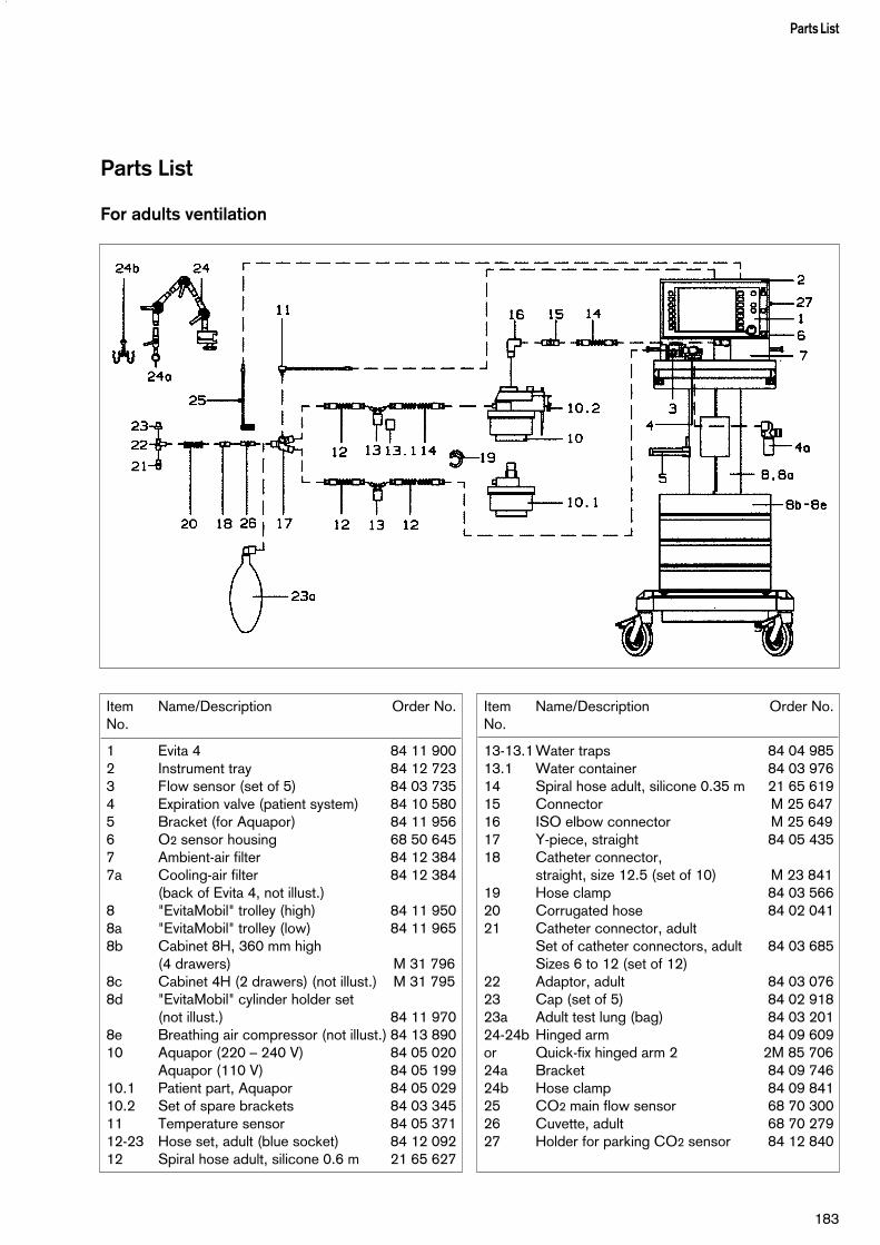
Parts List
For adults ventilation
183
Parts List
Item Name/Description Order No.No.
1 Evita 4 84 11 9002 Instrument tray 84 12 7233 Flow sensor (set of 5) 84 03 7354 Expiration valve (patient system) 84 10 5805 Bracket (for Aquapor) 84 11 9566 O2 sensor housing 68 50 6457 Ambient-air filter 84 12 3847a Cooling-air filter 84 12 384
(back of Evita 4, not illust.)8 "EvitaMobil" trolley (high) 84 11 9508a "EvitaMobil" trolley (low) 84 11 9658b Cabinet 8H, 360 mm high
(4 drawers) M 31 7968c Cabinet 4H (2 drawers) (not illust.) M 31 7958d "EvitaMobil" cylinder holder set
(not illust.) 84 11 9708e Breathing air compressor (not illust.) 84 13 89010 Aquapor (220 – 240 V) 84 05 020
Aquapor (110 V) 84 05 19910.1 Patient part, Aquapor 84 05 02910.2 Set of spare brackets 84 03 34511 Temperature sensor 84 05 37112-23 Hose set, adult (blue socket) 84 12 09212 Spiral hose adult, silicone 0.6 m 21 65 627
Item Name/Description Order No.No.
13-13.1 Water traps 84 04 98513.1 Water container 84 03 97614 Spiral hose adult, silicone 0.35 m 21 65 61915 Connector M 25 64716 ISO elbow connector M 25 64917 Y-piece, straight 84 05 43518 Catheter connector,
straight, size 12.5 (set of 10) M 23 84119 Hose clamp 84 03 56620 Corrugated hose 84 02 04121 Catheter connector, adult
Set of catheter connectors, adult 84 03 685Sizes 6 to 12 (set of 12)
22 Adaptor, adult 84 03 07623 Cap (set of 5) 84 02 91823a Adult test lung (bag) 84 03 20124-24b Hinged arm 84 09 609or Quick-fix hinged arm 2 2M 85 70624a Bracket 84 09 74624b Hose clamp 84 09 84125 CO2 main flow sensor 68 70 30026 Cuvette, adult 68 70 27927 Holder for parking CO2 sensor 84 12 840

For paediatric ventilation
184
Parts List
Item Name/Description Order No.No.
1 Evita 4 84 11 9002 Instrument tray 84 12 7233 Flow sensor (set of 5) 84 03 7354 Expiration valve (patient system) 84 10 5805 Bracket (for Aquapor) 84 11 9566 O2 sensor housing 68 50 6457 Ambient-air filter 84 12 3847a Cooling-air filter 84 12 384
(back of Evita 4, not illust.)8 "EvitaMobil" trolley (high) 84 11 9508a "EvitaMobil" trolley (low) 84 11 9658b Cabinet 8H, 360 mm high
(4 drawers) M 31 7968c Cabinet 4H (2 drawers) (not illust.) M 31 7958d "EvitaMobil" cylinder holder set
(not illust.) 84 11 9708e Breathing air compressor (not illust.)84 13 89024-24b Hinged arm 84 09 609or Quick-fix hinged arm 2 2M 85 70624a Bracket 84 09 74624b Hose clamp 84 09 84126-28 Humidifier, basic unit MR 730
(Fisher & Paykel) 84 11 04626 Hose heater adapter 84 11 09727 Mounting set (clamps for rail) 84 11 07428 Double temperature sensor 84 11 04829-30 Humidifier chamber MR 340 84 11 047
Item Name/Description Order No.No.
30 Filter paper (set of 200, not illustr.) 84 11 07331 Single-strand wire 1.5 m (not illustr.) 84 11 05032-43 Hose set, paediatrics
(Fisher & Paykel) 84 12 08132-32a Condensation trap, expiration 84 09 62732 Water container 84 03 97633 Double conical connector 84 09 89734 Temperature sensor mounting 84 11 04435 Adapter K90 84 03 07536 Cap 84 01 64537 Bellows, paediatric, complete 84 09 74238 Corrugated hose, flex, 0.13 m 84 09 63439 Catheter connector, size 11 M 19 35140 Spiral hose, paediatric,
silicone 22/10, 0.40 m 21 65 85641 Spiral hose, paediatric,
silicone 22/10, 1.10 m 21 65 65142 Spiral hose, paediatric,
silicone 10/10, 0.60 m 21 65 82143 Spiral hose, paediatric,
silicone 22/10, 0.60 m 21 65 84844 Hose heater 1.10 m 84 11 04545 Bacterial filter 84 09 71646 CO2 main flow sensor 68 70 30047 Cuvette, paediatrics 68 70 28048 Holder for parking CO2 sensor 84 12 840

Order List
185
Order List
Name/Description Order No.
Hose set, paediatric (Fisher & Paykel) 84 12 081consisting of: hose heater 84 11 045,patient hoses, water traps, Y-piece, catheter connectors
Bacterial filter 84 09 716
For CO2 measurement
Test filter 68 70 281
Calibration set 84 12 710
Test gas cylinder 5 Vol.% CO2, 95 Vol.% N2 86 50 435
CO2 main flow sensor 68 70 300
Holder for parking CO2 sensor 84 12 840
Special accessories
Instrument tray 84 12 723
Wall bracket, module 2000 Type 13 84 08 613alternative to trolley
Pneumatic medicament nebuliser 84 12 935
For manual ventilation:Resutator 2000 21 20 046Child Resutator 2000 21 20 984Baby Resutator 21 20 941Hook for Resutator M 26 349
Adult test lung 84 03 201
"EvitaMobil" trolley (high) 84 11 950"EvitaMobil" trolley (low) 84 11 965
For trolley:Cabinet 8H, 360 mm high(4 drawers) M 31 796Cabinet 4H (2 drawers) M 31 795"EvitaMobil" cylinder holder set 84 11 970Set of cabinet mountings for trolley 84 09 018Modification set – socket strip 84 11 969
Breathing air compressor 84 13 890for supplying Evita 4 with medical air
MEDIBUS cable 83 06 488
Printer cable 83 06 489
Water trap for expiration valve 84 13 125
Name/Description Order No.
Basic unit
Evita 4 84 11 900
Accessories required for operation
Hinged arm 84 09 609orQuick-fix hinged arm 2 2M 85 706
O2 connecting hose 3 m, blue M 29 231orO2 connecting hose 5 m, blue M 29 251orO2 connecting hose 3 m, neutral colour M 34 403orO2 connecting hose 5 m, neutral colour M 34 404
Medical air connecting hose 3 m, yellow M 29 239orMedical air connecting hose 5 m, yellow M 29 259 orMed. air connect. hose 3 m, neutral colour M 34 408orMed. air connect. hose 5 m, neutral colour M 34 409
Trolley 84 11 680
For adult ventilation
Temperature sensor 84 05 371
Aquapor humidifier 84 05 020
Set of spare brackets 84 03 345
Hose set, adult 84 12 092consisting of: patient hoses, water traps, Y-piece, catheter connectors
For paediatric ventilation
Humidifier, basic unit, MR 730 84 11 097(Fisher & Paykel),incl. adaptor, hose heater
Mounting set (rail brackets) 84 11 074
Humidifier chamber, MR 340 84 11 047
Double temperature sensor 84 11 048
Single-strand wire, 1.5 m 84 11 050
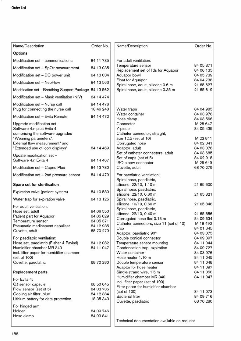
Name/Description Order No.
Options
Modification set – communications 84 11 735
Modification set – SpO2 measurement 84 13 035
Modification set – DC power unit 84 13 034
Modification set – NeoFlow 84 13 563
Modification set – Breathing Support Package 84 13 562
Modification set – Mask ventilation (NIV) 84 14 474
Modification set – Nurse call 84 14 476Plug for connecting the nurse call 18 46 248
Modification set – Evita Remote 84 14 472
Upgrade modification set – Software 4.n plus Evita 4,comprising the software upgrades "Weaning parameters", External flow measurement" and "Extended use of loop displays" 84 14 469
Update modification set – Software 4.n Evita 4 84 14 467
Modification set – Capno Plus 84 13 780
Modification set – 2nd pressure sensor 84 14 479
Spare set for sterilisation
Expiration valve (patient system) 84 10 580
Water trap for expiration valve 84 13 125
For adult ventilation:Hose set, adult 84 06 550Patient part for Aquapor 84 05 029Temperature sensor 84 05 371Pneumatic medicament nebuliser 84 12 935Cuvette, adult 68 70 279
For paediatric ventilation:Hose set, paediatric (Fisher & Paykel) 84 12 082Humidifier chamber MR 340 84 11 047incl. filter paper for humidifier chamber (set of 100)Cuvette, paediatric 68 70 280
Replacement parts
For Evita 4:O2 sensor capsule 68 50 645Flow sensor (set of 5) 84 03 735Cooling air filter, blue 84 12 384Lithium battery for data protection 18 35 343
For hinged arm:Holder 84 09 746Hose clamp 84 09 841
Name/Description Order No.
For adult ventilation:Temperature sensor 84 05 371Replacement set of lids for Aquapor 84 06 135Aquapor bowl 84 05 739Float for Aquapor 84 04 738Spiral hose, adult, silicone 0.6 m 21 65 627Spiral hose, adult, silicone 0.35 m 21 65 619
Water traps 84 04 985Water container 84 03 976Hose clamp 84 03 566Connector M 25 647Y-piece 84 05 435Catheter connector, straight, size 12.5 (set of 10) M 23 841Corrugated hose 84 02 041Adaptor, adult 84 03 076Set of catheter connectors, adult 84 03 685Set of caps (set of 5) 84 02 918ISO elbow connector M 25 649Cuvette, adult 68 70 279
For paediatric ventilation:Spiral hose, paediatric, silicone, 22/10, 1.10 m 21 65 600Spiral hose, paediatric, silicone, 22/10, 0.60 m 21 65 821Spiral hose, paediatric, silicone, 10/10, 0.60 m 21 65 848Spiral hose, paediatric,silicone, 22/10, 0.40 m 21 65 856Corrugated hose flex 0.13 m 84 09 634Catheter connectors, size 11 (set of 10) M 19 490Cap 84 01 645Adaptor, paediatric 90° 84 03 075Double conical connector 84 09 897Temperature sensor mounting 84 11 044Condensation trap, expiration 84 09 727Water container 84 03 976Hose heater 1.10 m 84 11 045Double temperature sensor 84 11 048Adaptor for hose heater 84 11 097Single-strand wire, 1.5 m 84 11 050Humidifier chamber MR 340 84 11 047incl. filter paper (set of 100)Filter paper for humidifier chamber (set of 100) 84 11 073Bacterial filter 84 09 716Cuvette, paediatric 68 70 280
Technical documentation available on request
Order List
186
What was new in Evita 4 software 2.n
Pinsp not linked to PEEP during BIPAP– The ventilation parameter Pinsp is set as an absolute
value. Pinsp is no longer affected by changes in PEEP.
Aids for setting pressure ventilation parameters– While setting the listed pressure ventilation
parameters, the parameter concerned appears as adashed line in the pressure curve Paw.
Continuous indication of the hose system leakageduring the leak test – The test step "Tightness of hose system" can be
selected separately in the "Device check" menu.Corrective measures can be undertaken with the aidof the continuous leakage indication.
Compensation of the hose system compliance– The hose system compliance determined during the
leak test is indicated at the end of the test.– The volume-controlled ventilation strokes are
automatically corrected with the calculated hosesystem compliance, as are the measured values forflow monitoring.
Leakage monitoring and compensation– Evita 4 compares the minute volume delivered on the
inspiration side with that measured on the expirationside, balances the leakage and indicates this as themeasured value MVleak.
– The applied tidal volume VTi is automatically correctedby the amount of the measured MVleak. The same alsoapplies for the Flow and VTe values measured on theexpiratory side.
– The measured minute volume values are not correctedfor safety reasons.
Apnoea ventilation with SIMV pattern– The patient can breathe spontaneously during apnoea
ventilation.– The apnoea ventilation frequency remains constant.
AutoFlow On/Off as start-up parameter– The AutoFlow function can be configured as a
start-up parameter so that AutoFlow is switched onautomatically when the device is switched on.
Loop display also for single strokes– In addition to the loop for a complete ventilation cycle,
e.g. in IPPV, the loop for a single breath (ventilated orspontaneous) can now also be displayed, for instancein such "mixed" ventilation modes as SIMV.
NeoFlow (optional)– Paediatric flow monitoring in paediatric and neonatal
ventilation is extended to include a flow sensorspecifically for neonates and positioned close to thepatient.
Breathing Support Package (optional)– To support spontaneous breathing.– To compensate the elastic and resistive resistance of
the respiratory system.
187
What was new in Evita 4 software 2.n
What was new in Evita 4 software 3.n
Additional screen languages – Portuguese– Russian– Arabic– Greek– Chinese
Additional function key » «– For blanking / unblanking the screen.
Independent lung ventilation ILV– For independent ventilation of each lung using two
Evita ventilators.
Additional function keye »Exsp. hold«– To extend expiration.– To occlude the ventilation system following expiration.
Medicament nebulisation– Can also be applied during paediatric ventilation.
Bronchial suctioning– In the patient modes »Paediatric« and »Neonates«,
Evita 4 increases the set O2 concentrationcommensurately, but not up to 100 % by volume.
Warning »Volume not constant«– Can be suppressed.
Automatic Tube Compensation ATC (optional)– For specific reduction of the breathing effort
attributable to the tube.
What was new in Evita 4 software 3.n
188
IndexAbbreviations...........................................................178Accessories............................................................... 11Adaptive minimum ventilation (MMV)........................ 168Adult ventilation..........................................................50Alarm limits................................................................ 77Alarm situations..........................................................78Alarm tone, cancelling................................................ 79Alarms..................................................................... 127Apnoea alarm setting..................................................77Apnoea ventilation................................................58, 76APRV.................................................................67, 168Aquapor.....................................................................32"Artificial noses".........................................................31ASB...................................................................63, 165Assembly (expiration valve).......................................142Assisted spontaneous breathing ASB.................63, 165AutoFlow ......................................................... 54, 162Automatic weaning (MMV)....................................... 168
Bacterial filter...................................................... 34, 35Battery operation (DC retrofit).................................. 186Bibliography.............................................................182BIPABAssist...................................................... 62, 167BIPAP, BIPAP/ASB........................................... 60, 166Body weight, setting...................................................51Bronchial suctioning...................................................91BTPS.......................................................................171
Calibration................................................................. 97Central alarm............................................................. 40Check before use...................................................... 42Classification........................................................... 157Cleaning.................................................................. 139CO2 calibration, reset.............................................. 106CO2 cuvette...............................................................34CO2 sensor............................................................... 34CO2 sensor calibration...............................................99CO2 zero alignment................................................. 100Compensation, hose system C.........................170, 187Compensation, leakage....................................170, 187Compressed gases....................................................37Configuration........................................................... 107Consumables....................................................183-186Control unit..........................................................27, 47Controls.............................................................17, 148Cooling air filter........................................................144CPAP, CPAP/ASB.................................................... 63Curves.......................................................................80
Date........................................................................ 125Description.............................................................. 159Device check............................................................. 42Disinfection..............................................................139Dismantling.............................................................. 136Disposal (batteries, O2 sensor)................................ 144
Electric power supply................................................ 36Equipment options................................................... 186Evita Remote..............................................................38Exp. hold....................................................................87Expiration valve.................................................. 30, 138External flow sources................................................. 99External interface..................................................... 124
Filter (cooling air).....................................................144Filter (hose system)..............................................34, 35Filter (room air / emergency valve)............................144First-time use............................................................. 41Flow measurement...................................................170Flow sensor......................................................... 26, 82Flow sensor calibration.............................................. 98FlowTrigger............................................................... 54Frequency alarm........................................................ 77Frequency-to-volume ratio RSB................................175
Gas supply................................................................ 37Glossary / abbreviations...........................................178
Heat and moisture exchanger.....................................31Heat exchanger..........................................................31HME.......................................................................... 31Hose system........................................................ 32, 35Humidification............................................................ 32Humidifier type...........................................................44
Ideal body weight.......................................................51Insp. hold...................................................................87Insp. O2 concentration for nebulisation.....................177Intended medical application...................................... 13Intended medical application...................................... 13Interface (external)................................................... 124Interfaces (external, serial)........................................124Intrinsic PEEP.................................................... 93, 176IPPV.......................................................................... 53IPPVAssist...................................................................54
Language...........................................................47, 125Leakage compensation............................................ 187Leakage test.............................................................. 46Logbook.................................................................... 85Loops........................................................................ 83Loudness.................................................................108
Mains power failure................................................... 36Mains power supply................................................... 36Maintenance...................................................... 11, 143Manual inspiration...................................................... 87Mask ventilation (NIV).............................................. 186Maximum negative inspiration pressure.....................175Measured values................................................ 80, 109Measurement procedure...................................... 93, 94
189
Index

Medicament nebulisation.................................... 88, 177Messages................................................................ 127MMV, MMV/ASB............................................... 65, 168Mobile telephones......................................................12Monitoring............................................................77, 80
Nebulisation.................................................88, 99, 177Nebuliser................................................................... 99Neonatal ventilation (modification set).......................186New features in earlier software versions..................187New features in this software version........................... 3NIF (Negative Inspiration Force)...............................175Notes.......................................................................127Nurse call...................................................................40
O2 sensor calibration................................................. 97O2 sensor capsule..................................................... 31O2 sensors................................................................ 31Occlusion pressure............................................ 94, 174Operating concept..................................................... 15Operation...................................................................49Optional equipment..................................................186Order list................................................................. 183
Paediatric ventilation.................................................. 50Parts list...................................................................183Patient mode..............................................................50Patient system (expiration valve)......................... 30, 138PLV....................................................................55, 160Power failure..............................................................36Preparation................................................................ 29Preparing.................................................................135Pressure limit Pmax............................................55, 160Pressure Support ASB.......................................63, 165Previous patient......................................................... 51Printer......................................................................124PS/ASB.............................................................63, 165
Reference curve display.............................................83Remedying alarm situations......................................127Remote Pad............................................................... 38Replacement parts............................................ 183-186Room air filter.......................................................... 144RSB (Rapid Shallow Breathing index)...................... 175
Screen freeze (stop image)........................................ 86Screen page »Alarm limits«.........................................24Screen page »Calibration«..........................................26Screen page »Configuration«......................................27Screen page »Measured values«................................ 25Screen page »Settings«..............................................22Screen page »Special procedures«............................ 26Screen pages............................................................ 21Settings............................................................. 49, 107Sigh................................................................... 54, 163SIMV, SIMV/ASB...............................................57, 164
Single-stroke display.................................................. 83Socket strip............................................................... 36Spare parts.......................................................183-186Standard screen........................................................ 22Standby..................................................................... 96Start-up procedure for AutoFlow ............................162Start-up values.........................................................119Switching on.............................................................. 50Symbols ..................................................................181
Tachypnoea alarm setting.......................................... 77Technical data..........................................................151Temperature sensor................................................... 33Test before use.......................................................... 42Test filter..................................................................102Test gas...................................................................103TGI............................................................................ 99Tightness................................................................... 46Time........................................................................ 125Touch-screen.............................................................17Tracheal gas insufflation............................................. 99Trends....................................................................... 82Troubleshooting....................................................... 127
UMDNS Code.........................................................157
Valve, expiration.................................................30, 138Ventilation hoses.................................................. 32, 35Ventilation modes.......................................................53Ventilation, monitoring................................................ 12Volume alarm............................................................. 77Volume, volume measurement..................................170
Weaning parameters................................................174What's what............................................................ 148
Zoom (loop)...............................................................83
190
Index

191
These Instructions for Use apply only toEvita 4with Serial No.:
If no Serial No. has been filled in byDräger these Instructions for Use areprovided for general information only andare not intended for use with any specificmachine or device.
90 37 207 - GA 5664.552 en Dräger Medical AG & Co. KGaA 3rd edition - December 2001Subject to alteration
Dräger Medical AG & Co. KGaAGermanyH Moislinger Allee 53 – 55
23542 LübeckT (04 51) 8 82 - 0X 26 80 70FAX (04 51) 8 82-20 80! http://www.draeger.com
çDirective 93/42/EECconcerning Medical Devices