
Evaporation/boiling on Thin Capillary Wick (I): … on Thin...Evaporation/boiling on Thin Capillary...
9
University of South Carolina College of Engineering and Computing Mechanical Engineering Department Evaporation/boiling on Thin Capillary Wick (I): Thickness Effects Chen Li, G. P. Peterson, and Y. Wang
-
Upload
truonghanh -
Category
Documents
-
view
230 -
download
1
Transcript of Evaporation/boiling on Thin Capillary Wick (I): … on Thin...Evaporation/boiling on Thin Capillary...
University of South Carolina College of Engineering and Computing Mechanical Engineering Department
Evaporation/boiling on Thin Capillary
Wick (I): Thickness Effects
Chen Li, G. P. Peterson, and Y. Wang
Chen LiGraduate Research Assistant
Student member of ASMERensselaer Polytechnic Institute,
Department of Mechanical, Aerospace and
Nuclear Engineering,
Troy, NY 12180
e-mail: [email protected]
G. P. PetersonProfessor and Chancellor
University of Colorado,
Boulder, CO 80309
e-mail: [email protected]
Yaxiong WangPrincipal Engineer
Foxconn Thermal Technology Inc.,
Austin, TX 78758
e-mail: [email protected]
Evaporation/Boiling in ThinCapillary Wicks „l…—WickThickness EffectsPresented here is the first of a two-part investigation designed to systematically identifyand investigate the parameters affecting the evaporation/boiling and critical heat flux(CHF) from thin capillary wicking structures. The evaporation/boiling heat transfer co-efficient, characteristics, and CHF were investigated under steady-state conditions for avariety of capillary structures with a range of wick thicknesses, volumetric porosities, andmesh sizes. In Part I of the investigation we describe the wicking fabrication process andexperimental test facility and focus on the effects of the capillary wick thickness. In PartII we examine the effects of variations in the volumetric porosity and the mesh size aswell as presenting detailed discussions of the evaporation/boiling phenomena from thincapillary wicking structures. An optimal sintering process was developed and employedto fabricate the test articles, which were fabricated using multiple, uniform layers ofsintered isotropic copper mesh. This process minimized the interface thermal contactresistance between the heated wall and the capillary wick, as well as enhancing thecontact conditions between the layers of copper mesh. Due to the effective reduction inthe thermal contact resistance between the wall and capillary wick, both the evaporation/boiling heat transfer coefficient and the critical heat flux (CHF) demonstrated dramatic
improvements, with heat transfer coefficients up to 245.5 kW/m2K and CHF values in
excess of 367.9 W/cm2, observed. The experimental results indicate that while theevaporation/boiling heat transfer coefficient, which increases with increasing heat flux, isonly related to the exposed surface area and is not affected by the capillary wick thick-ness, the CHF for steady-state operation is strongly dependent on the capillary wickthickness and increases proportionally with increase in the wick thickness. In addition tothese observations, the experimental tests and subsequent analysis have resulted in thedevelopment of a new evaporation/boiling curve for capillary wicking structures, whichprovides new physical insights into the unique nature of the evaporation/boiling processin these capillary wicking structures. Sample structures and fabrication processes, aswell as the test procedures are described in detail and the experimental results andobservations are systematically presented and analyzed. �DOI: 10.1115/1.2349507�
Keywords: experimental study, evaporation, boiling, heat transfer, CHF, thin capillarywick, thickness effects
1 Introduction
Previous investigations of evaporation/boiling from capillary
wicking structures �1–10� have demonstrated that capillary pump-
ing can be an effective way to passively enhance both the heat
transfer coefficient and the critical heat flux �CHF� in evaporation/
boiling heat transfer. In these structures, the enhanced distribution
of the liquid on the surface, the increase in the effective surface
area, the enhancement of the supply of fluid to the heated area
through capillary pumping, and the change in the nucleation site
size distribution, all result in significant improvements in both
heat transfer performance and the critical heat flux �1�. The ability
to predict the critical heat flux and the evaporation/boiling heat
transfer coefficient of capillary wicking structures is of critical
importance to the application of these structures to two-phase heat
transfer devices, such as heat pipes, loop heat pipes �LHP�, and
capillary pumped loops �CPL�, etc. However, the effective utili-
zation of this capability is strongly dependent on a complete un-
derstanding of the functional relationship between the various pa-
rameters. The recent research on capillary wick performance and
modeling is summarized in Table 1. As shown, Liter and Kaviany
�1� focused on modulated, capillary wick structure development
and successfully improved the CHF by a factor of 3 when com-pared to the CHF on plane surfaces for pool boiling heat transfer.The theoretical models developed were also capable of accuratelypredicting the CHF. Williams and Harris �3� developed a step-graded capillary wick structure using stainless steel felt to en-hance the capillary limit. Hanlon and Ma �8� investigated the liq-uid film evaporation and capillary wick thickness effects forsintered copper particle beds, and found that thin film evaporationon the top surface of the wick is the key factor in the improvementof the heat transfer efficiency of the capillary wick and that anoptimum thickness exists for a given particle size. Mughal andPlumb �9� improved the capillary wick performance by machiningchannels on a planar porous media surface. Lao and Zhao �10�studied the evaporation from a channeled, heated wall under an-tigravity conditions, with glass particle beds of varying sizes, andobserved that nucleate boiling did not stop or retard the capillarydriven flow through the capillary wick structure as previously hy-pothesized.
In reviewing the recent investigations of evaporation/boiling orpool boiling from the porous media coated surfaces listed in Table1, it is apparent that the geometric properties of the structure, suchas the wick thickness, volumetric porosity, and particle size,should always be carefully considered. However, of equal impor-tance and not so obvious is the importance of the contact condi-
Contributed by the Heat Transfer Division of ASME for publication in the JOUR-
NAL OF HEAT TRANSFER. Manuscript received August 28, 2005; final manuscript re-
ceived January 11, 2006. Review conducted by Raj M. Manglik.
1312 / Vol. 128, DECEMBER 2006 Copyright © 2006 by ASME Transactions of the ASME
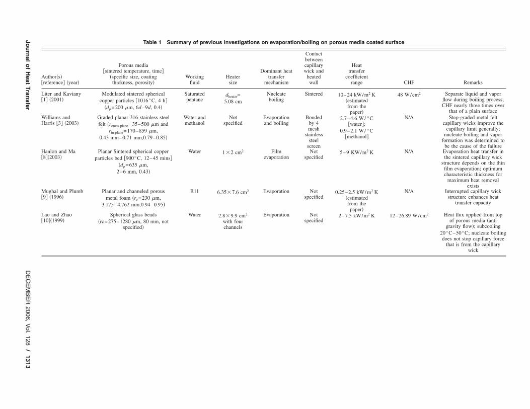
Table 1 Summary of previous investigations on evaporation/boiling on porous media coated surface
Author�s��reference� �year�
Porous media�sintered temperature, time�
�specific size, coatingthickness, porosity�
Workingfluid
Heatersize
Dominant heattransfer
mechanism
Contactbetweencapillarywick and
heatedwall
Heattransfer
coefficientrange CHF Remarks
Liter and Kaviany�1� �2001�
Modulated sintered spherical
copper particles �1016°C, 4 h�
�dp=200 �m, 6d–9d, 0.4�
Saturatedpentane
dheater=
5.08 cm
Nucleateboiling
Sintered 10–24 kW/m2 K�estimatedfrom thepaper�
48 W/cm2 Separate liquid and vaporflow during boiling process;CHF nearly three times over
that of a plain surface
Williams andHarris �3� �2003�
Graded planar 316 stainless steel
felt �rcross-plane=35–500 �m and
rin-plane=170–859 �m,
0.43 mm–0.71 mm,0.79–0.85�
Water andmethanol
Notspecified
Evaporationand boiling
Bondedby 4mesh
stainlesssteel
screen
2.7–4.6 W/ °C�water�;
0.9–2.1 W/ °C�methanol�
N/A Step-graded metal feltcapillary wicks improve the
capillary limit generally;nucleate boiling and vapor
formation was determined tobe the cause of the failure
Hanlon and Ma�8��2003�
Planar Sintered spherical copper
particles bed �900°C, 12–45 mins�
�dp=635 �m,
2–6 mm, 0.43�
Water 1�2 cm2 Filmevaporation
Notspecified
5–9 KW/m2 K N/A Evaporation heat transfer inthe sintered capillary wick
structure depends on the thinfilm evaporation; optimumcharacteristic thickness for
maximum heat removalexists
Mughal and Plumb�9� �1996�
Planar and channeled porous
metal foam �rc=230 �m,
3.175–4.762 mm,0.94–0.95�
R11 6.35�7.6 cm2 Evaporation Notspecified
0.25–2.5 kW/m2 K�estimatedfrom thepaper�
N/A Interrupted capillary wickstructure enhances heat
transfer capacity
Lao and Zhao�10��1999�
Spherical glass beads
�rc=275–1280 �m, 80 mm, notspecified�
Water 2.8�9.9 cm2
with fourchannels
Evaporation Notspecified
2–7.5 kW/m2 K 12–26.89 W/cm2 Heat flux applied from topof porous media �anti
gravity flow�; subcooling
20°C–50°C; nucleate boilingdoes not stop capillary force
that is from the capillarywick
Jo
urn
al
of
Hea
tT
ran
sfe
rD
EC
EM
BE
R200
6,
Vol.
128
/13
13
tions between the heated wall and the capillary wick. Furtherstudy indicates that this condition is actually the dominant factorin the determination of the overall thermal resistance between theheated wall and the capillary wick, and as a result, to a largeextent, governs the overall behavior of evaporative/boiling heattransfer and CHF. As indicated in Table 1, Liter and Kaviany �1�used a sintering process to enhance the contact conditions and asa result, obtained very high heat transfer coefficients, even forpentane in pool boiling. Williams and Harris �3� bonded the cap-illary wicking material, in this case a coarse stainless steel mesh,onto the heating surface. In the other investigations reviewed andsummarized in Table 1, the techniques employed to control oraugment the contact conditions between the capillary wick and theheated wall were not specified.
The principal enhancements of the capillary wick structure canbe divided into four categories, those resulting from �1� the reduc-tion in the heat flux density on the heated wall, due to the fineffect; �2� the presence of contact points connecting the capillarywick and the wall, which effectively interrupts the formation ofthe vapor film and thereby reduces the critical hydrodynamicwavelength; �3� the increased nucleation site density and evapo-ration area; and �4� the improved liquid supply resulting from thecapillary induced flow. In the current investigation, an optimumsintering process was developed and employed to minimize thecontact thermal resistance between the individual layers of coppermesh, as well as between the copper mesh and the heated wall. Allof the experimental results presented herein utilized an identical,optimized sintering process.
Although capillary wicks have been studied extensively, theeffect of thickness has not been adequately addressed. Classicalnucleate boiling theory indicates that the bubble departure diam-
eter for a heated wall is on the order of 1 mm �12�, and hence, inthe current investigation, the range of thickness investigated is
limited to 0.21 to 0.82 mm, which is much smaller than the
bubble departure diameter, Dd. Given these conditions, it is rea-sonable to assume that no bubbles will depart from the heatedsurface and that there will be no bubble flow inside the capillarywicking structure.
The elimination of bubble departure results in two principal
advantages: first, the bubble generation frequency f =1/ �tw+ td� is
significantly increased without increasing the time required for the
bubbles to depart, td; and second, there is no reduction in theliquid supply, due to the presence of bubbles trapped within theporous media. Based upon this analysis, it was hypothesized thatthe heat transfer from capillary wicking structures, with thick-
nesses less than the bubble departure diameter, Dd, could lead tosignificant overall enhancements.
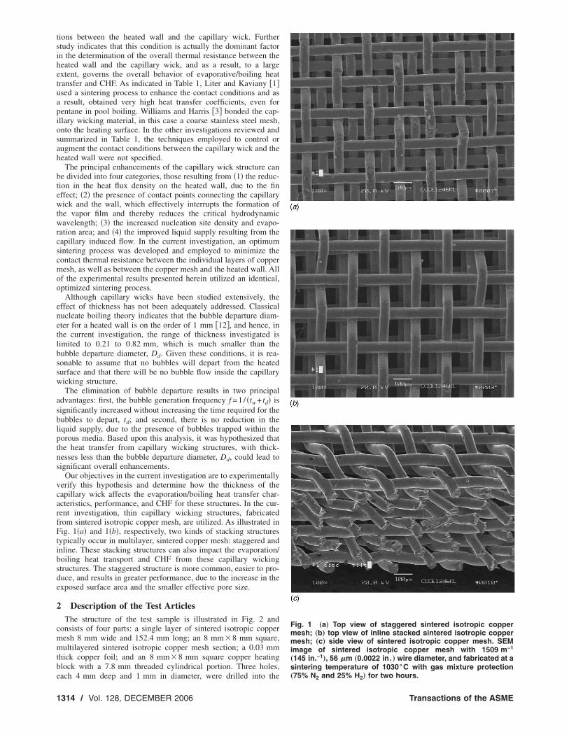
Our objectives in the current investigation are to experimentallyverify this hypothesis and determine how the thickness of thecapillary wick affects the evaporation/boiling heat transfer char-acteristics, performance, and CHF for these structures. In the cur-rent investigation, thin capillary wicking structures, fabricatedfrom sintered isotropic copper mesh, are utilized. As illustrated inFig. 1�a� and 1�b�, respectively, two kinds of stacking structurestypically occur in multilayer, sintered copper mesh: staggered andinline. These stacking structures can also impact the evaporation/boiling heat transport and CHF from these capillary wickingstructures. The staggered structure is more common, easier to pro-duce, and results in greater performance, due to the increase in theexposed surface area and the smaller effective pore size.
2 Description of the Test Articles
The structure of the test sample is illustrated in Fig. 2 andconsists of four parts: a single layer of sintered isotropic copper
mesh 8 mm wide and 152.4 mm long; an 8 mm�8 mm square,
multilayered sintered isotropic copper mesh section; a 0.03 mm
thick copper foil; and an 8 mm�8 mm square copper heating
block with a 7.8 mm threaded cylindrical portion. Three holes,
each 4 mm deep and 1 mm in diameter, were drilled into the
Fig. 1 „a… Top view of staggered sintered isotropic coppermesh; „b… top view of inline stacked sintered isotropic coppermesh; „c… side view of sintered isotropic copper mesh. SEMimage of sintered isotropic copper mesh with 1509 m−1
„145 in.−1…, 56 �m „0.0022 in. … wire diameter, and fabricated at asintering temperature of 1030°C with gas mixture protection„75% N2 and 25% H2… for two hours.
1314 / Vol. 128, DECEMBER 2006 Transactions of the ASME
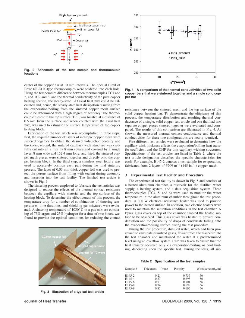
center of the copper bar at 10 mm intervals. The Special Limit ofError �SLE� K-type thermocouples were soldered into each hole.Using the temperature difference between thermocouples TC1 and2, and TC2 and 3, and the thermal conductivity of the pure copperheating section, the steady-state 1-D axial heat flux could be cal-culated and, hence, the steady-state heat dissipation resulting fromthe evaporation/boiling from the sintered copper mesh surfacecould be determined with a high degree of accuracy. The thermo-couple closest to the top surface, TC1, was located at a distance of
0.5 mm from the surface and when coupled with the axial heatflux, was used to estimate the surface temperature of the copperheating block.
Fabrication of the test article was accomplished in three steps:first, the required number of layers of isotropic copper mesh weresintered together to obtain the desired volumetric porosity andthickness; second, the sintered capillary wick structure was care-
fully cut into an 8 mm by 8 mm square and covered by a single
layer, 8 mm wide and 152.4 mm long; and third, the sintered cop-per mesh pieces were sintered together and directly onto the cop-per heating block. In the third step, a stainless steel fixture wasused to accurately position each part during the final sintering
process. The layer of 0.03 mm thick copper foil was used to pro-tect the porous surface from filling with sealant during assemblyand insertion into the test facility. The finished test article isshown in Fig. 3.
The sintering process employed to fabricate the test articles wasdesigned to reduce the effects of the thermal contact resistancebetween the capillary wick material and the top surface of theheating block. To determine the effectiveness of this process, thetemperature drop for a number of combinations of sintering tem-peratures, time durations, and shielding gas mixtures were evalu-
ated. A sintering temperature of 1030°C in a gas mixture consist-ing of 75% argon and 25% hydrogen for a time of two hours, wasfound to provide the optimal conditions for reducing the contact
resistance between the sintered mesh and the top surface of thesolid copper heating bar. To demonstrate the efficiency of thisprocess, the temperature distribution and resulting thermal con-ductance of a single, solid copper test article and one that had twoseparate copper pieces sintered together were evaluated and com-pared. The results of this comparison are illustrated in Fig. 4. Asshown, the measured thermal contact conductance and thermalconductivities for these two configurations are nearly identical.
Five different test articles were evaluated to determine how thecapillary wick thickness affects the evaporation/boiling heat trans-fer coefficient and the CHF for thin capillary wicking structures.Specifications of the test articles are listed in Table 2, where thetest article designation describes the specific characteristics foreach. For example, E145-2 denotes a test sample for evaporation,
fabricated from 2 layers of 5709 m−1 �145 in.−1� copper mesh.
3 Experimental Test Facility and Procedure
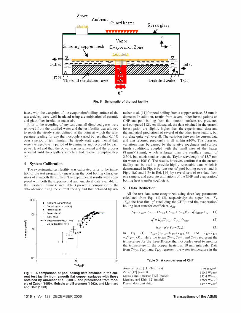
The experimental test facility is shown in Fig. 5 and consists ofa heated aluminum chamber, a reservoir for the distilled watersupply, a heating system, and a data acquisition system. Threethermocouples �TC4, 5, and 6� were used to monitor the watertemperature in the aluminum chamber throughout the test proce-
dure. A 300 W electrical resistance heater was used to providepower to the heated surface. In addition, two electric heaters wereused to maintain the saturation conditions in the test chamber. APyrex glass cover on top of the chamber enabled the heated sur-face to be observed. This glass cover was heated to prevent con-densation and the possibility of drops of condensate falling ontothe evaporation/boiling surface during the test procedure.
During the test procedure, distilled water, which had been pro-cessed to eliminate dissolved gases, flowed from the reservoir intothe test chamber and maintained the water at a predeterminedlevel using an overflow system. Care was taken to ensure that theheat transfer occurred only via evaporation/boiling or pool boil-ing, depending upon the specific test. During the tests, all sur-
Fig. 2 Schematic of the test sample and thermocouplelocations
Fig. 3 Illustration of a typical test article
Fig. 4 A comparison of the thermal conductivities of two solidcopper bars that were sintered together and a single solid cop-per bar
Table 2 Specification of the test samples
Sample # Thickness �mm� Porosity Wirediameter��m�
E145-2 0.21 0.737 56E145-4 0.37 0.693 56E145-6 0.57 0.701 56E145-8 0.74 0.698 56E145-9 0.82 0.696 56
Journal of Heat Transfer DECEMBER 2006, Vol. 128 / 1315
faces, with the exception of the evaporation/boiling surface of thetest articles, were well insulated using a combination of ceramicand glass fiber insulation materials.
Prior to the recording of any test data, all dissolved gases wereremoved from the distilled water and the test facility was allowedto reach the steady state, defined as the point at which the tem-
perature reading for any thermocouple varied by less than 0.1°Cover a period of ten minutes. The steady-state experimental datawere averaged over a period of five minutes and recorded for eachpower level and then the power was incremented and the processrepeated until the capillary structure had reached complete dry-out.
4 System Calibration
The experimental test facility was calibrated prior to the initia-tion of the test program by measuring the pool boiling character-istics of a smooth flat surface. The experimental results were com-pared with both the experimental and analytical data available inthe literature. Figure 6 and Table 3 present a comparison of thedata obtained using the current facility and that obtained by Au-
racher et al. �11� for pool boiling from a copper surface, 35 mm indiameter. In addition, results from several other investigations onCHF and pool boiling from flat, smooth surfaces are presentedand compared �12�. As illustrated, the data obtained in the currentinvestigation are slightly higher than the experimental data andthe analytical predictions of several of the other investigators, butcorrelate quite well overall. The variation between the current data
and that reported previously is all within ±10%. The observedvariations may be caused by the relative roughness and surfacefinish conditions, coupled with the small size of the heater
�8 mm�8 mm�, which is larger than the capillary length of
2.504, but much smaller than the Taylor wavelength of 15.7 mm
for water at 100°C. The results, however, confirm that the currentfacility can be used to provide highly repeatable data, which isdemonstrated in Fig. 6 by two sets of pool boiling curves, and inFigs. 1�a� and 1�b� in Ref. �14� by several sets of test data fromone sample, and accurate estimations of the CHF and evaporation/boiling heat transfer coefficient.
5 Data Reduction
All the test data were categorized using three key parameters
calculated from Eqs. �1�–�3�, respectively: the super heat, TW
-Tsat; the heat flux, q� �including the CHF�; and the evaporation/
boiling heat transfer coefficient, heff.
TW − Tsat = TTC1 − �TTC4 + TTC5 + TTC6�/3 − q�tSTC1/Kcu, �1�
q� = Kcu�TTC2 − TTC1�/thole, �2�
heff = q�/�TW − Tsat� . �3�
In Eq. �1�, Tsat= �TTC4+TTC5+TTC6� /3 and TW=TTC1
−q�tSTC1 /Kcu. Here the terms TTC1, TTC2, and TTC3 represent thetemperature for the three K-type thermocouples used to monitor
the temperature in the copper heater, at 10 mm intervals. Data
from TTC4, TTC5, and TTC6 represent the water temperature in the
Fig. 5 Schematic of the test facility
Fig. 6 A comparison of pool boiling data obtained in the cur-rent test facility from smooth flat copper surfaces with thoseobtained by Auracher et al. „2003…, and predictions from mod-els of Zuber „1959…, Moissis and Berenson „1962…, and Lienhardand Dhir „1973…
Table 3 A comparison of CHF
Auracher et al. �11� �Test data� 139 W/cm2
Zuber �12� �model� 110.8 W/cm2
Moissis and Berenson �12� �model� 152.4 W/cm2
Lienhard and Dhir �12� �model� 126.9 W/cm2
Present data �test data� 149.7 W/cm2
1316 / Vol. 128, DECEMBER 2006 Transactions of the ASME
test chamber. Using the measured temperature, TTC1, and the
known thermal conductivity, Kcu, the temperature at the bottom of
the capillary wick structure, TW, can be derived; and using TTC1
and TTC2, the heat flux, q�, dissipated through evaporation/boilingunder steady-state conditions can be determined. With these twovalues, the effective heat transfer coefficient can be estimated byEq. �3�.
The uncertainties of the temperature measurements, the length
�or width� and the mass are ±0.5°C, 0.01 mm, and 0.1 mg, re-spectively. A Monte Carlo error of propagation simulation indi-cated the following 95% confidence level for the computed re-
sults: the heat flux was less than ±5.5 W/cm2; the heat transfer
coefficient was less than ±20%; the superheat �Twall-Tsat� was less
than ±1.3°C, and the porosity, �, was less than ±1.5%.
6 Results and Discussion
The experiments were conducted at atmospheric pressure withdegassed, distilled water. All surfaces were carefully cleaned us-
ing Duraclean™ 1075 prior to each test sequence to assure theidentical surface wetting characteristics. Typical test results aresummarized in Figs. 7–9 and the results are presented in terms ofthe heat flux, superheat, CHF, and heat transfer coefficient. In thisinvestigation, the volumetric porosities and pore sizes of all thesamples were held constant throughout all of the tests and all datawere obtained under steady-state conditions.
6.1 Contact Conditions between Heater and CapillaryWick Structure. From the literature review, it is apparent that thecontact conditions at the heated wall-capillary wick interface havebeen neglected in most of the previous investigations. This is im-portant to note since the contact conditions are a critical factor and
can significantly improve the evaporation/boiling heat transport inthe capillary wick and, in turn, significantly enhance the CHF. Asmentioned previously, the principal functions of the capillary wickstructure can be divided into four categories: those resulting from�1� the reduction in the heat flux density on the heated wall due tothe fin effect; �2� the presence of the contact points connecting the
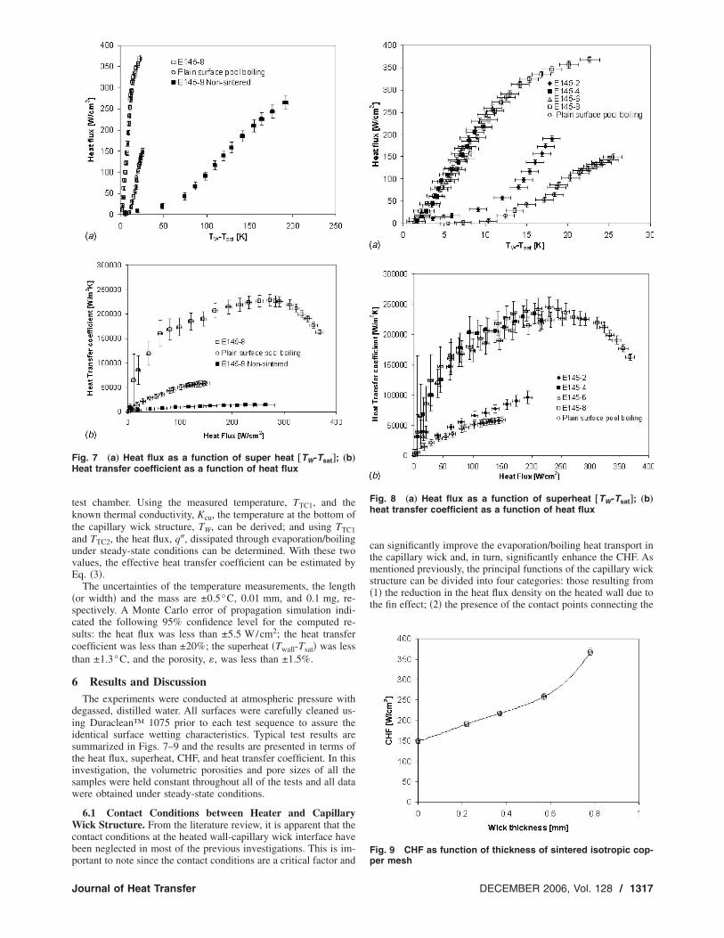
Fig. 7 „a… Heat flux as a function of super heat †TW-Tsat‡; „b…Heat transfer coefficient as a function of heat flux
Fig. 8 „a… Heat flux as a function of superheat †TW-Tsat‡; „b…heat transfer coefficient as a function of heat flux
Fig. 9 CHF as function of thickness of sintered isotropic cop-per mesh
Journal of Heat Transfer DECEMBER 2006, Vol. 128 / 1317
capillary wick and wall, which interrupts the formation of thevapor film or reduces the critical hydrodynamic wavelength; �3�the increased nucleation site density and evaporation area; and �4�the improved liquid supply resulting from the capillary inducedflow.
In the evaporation/boiling from capillary wicking structures, amajority of the heat is conducted from the solid wall to the cap-illary wick, where it is then dissipated via evaporation/boilingfrom the exposed hot surfaces. If the capillary wicking structure isnot sintered or not attached directly to the solid surface, a thinliquid film may exist. This film will significantly increase the ther-mal resistance between the layers of the wick or between the solidheated wall and the capillary wick. As a result, thermal energywill be accumulated at the heated wall and cause relatively higherwall temperatures. This will, in turn, result in a significant reduc-tion in both the heat transfer performance and the CHF.
In order to maximize and properly evaluate the evaporation/boiling heat transfer performance from the capillary wicks, and,moreover, to maintain evaporation/boiling instead of thin filmboiling on the heated wall, it is essential to ensure good contactconditions between the heater and the capillary wicking structure.Figures 7�a� and 7�b� present three sets of data and illustrate howimportant this contact is, and how significant the differences re-sulting from variations in the contact conditions can be. The firstset of data was obtained in the current investigation using testarticle E145-8, which was sintered directly onto the top surface ofthe heated wall using the sintering procedure described previ-ously. These data are compared with data obtained for a sample inwhich the sintered capillary structure was bonded to the heatingsurface by a thermal epoxy �ATI Electro-Grease 8501� and withpool boiling data obtained from a plain flat surface. As illustratedin Figs. 7�a� and 7�b�, the dissipated heat flux and the resultingheat transfer coefficient from E145-9 are both significantly lowerthan those obtained from E145-8 at the same superheat and heatflux, respectively. In addition and worthy of special note is thefact that the heat transfer performance of E145-9 is also signifi-cantly less than that obtained from pool boiling of a plain surface.This dramatic reduction is due to the increase in the contact ther-mal resistance, which dominates the temperature difference or thesuperheat as defined in this paper �also employed in most otherinvestigations�, between the sintered capillary wick and the heatedsurface in sample E145-9.
6.2 Effects of Capillary Wick Thickness on Evaporation/Boiling Heat Transfer Performance. Figure 8�a� presents theheat flux as a function of the superheat, while Fig. 8�b� illustratesthe effective heat transfer coefficient as a function of the heat flux.As indicated, the increased nucleation site density and the en-hanced evaporation/boiling surface area, result in a substantiallybetter performance than pool boiling from a flat surface. Visualobservation indicated that the evaporation and boiling heat trans-fer occurred simultaneously when the heat flux reached a certainvalue, which was observed to vary with the capillary wick thick-ness. During the tests, small bubbles were observed at low heatfluxes, and although the two phases coexist in the porous media,the bubbles or vapor could easily escape from the liquid to thevapor space immediately adjacent to the capillary wick surface.For a given volumetric porosity and pore size, the evaporation/boiling heat transfer coefficient from the sintered copper meshclearly indicates a very weak dependence on the capillary wickthickness. When the mesh number and wire diameter are heldconstant, the surface area of the mesh within the test articles willincrease proportionally with respect to the thickness, while theexposed surface area remains constant. As illustrated in Fig. 8�b�,prior to reaching CHF the heat transfer coefficients for the variousthicknesses are nearly identical, except for sample E145-2. Thisimplies that it is the exposed surface, rather than the total surfacearea of the mesh within the test articles that dominates the heattransfer performance in the evaporation/boiling on the capillarywick. One possible explanation for the lower performance of
E145-2 is that the surface is actually flooded, due to the difficul-ties associated with accurately controlling the water level in verythin layers of these capillary structures. This flooding could resultin a different heat transfer mechanism than that which occurs inthicker capillary wicking structures. With this exception, however,the test results clearly indicated that the heat transfer performanceon thin capillary wicks is not directly related to the capillary wickthickness. These results also imply that care should be taken tocontrol the liquid level for very thin materials in order to developaccurate evaporation/boiling heat transfer models.
The highest performance was obtained for the 0.21 mm thickcapillary wick at the CHF, however, when the capillary wick is
thicker than 0.37 mm, the maximum heat transfer coefficient isachieved before the CHF has been reached. This implies that thecapillary pumping is still effective, even when local dry out oc-
curs. The data obtained for the 0.21 mm thick capillary wick aresomewhat different from the other samples tested. The experimen-tal results also suggest that the capillary wick thickness range foroptimal evaporation/boiling heat transfer performance is from
0.37 mm to the bubble departure diameter, to D, for sintered cop-per mesh.
6.3 Effects of Capillary Wick Structure Thickness on theEvaporation/Boiling Characteristics. Figure 8�a� indicates thatthe evaporation/boiling inception superheats are significantly re-duced through capillary wicking, compared with that obtained forpool boiling on a plain surface. The value of inception wall su-
perheat varies for samples E145-4�8 �14�, which indicates thatthis parameter is dependent on wick thickness. Generally the wallsuperheat at CHF is less than that of pool boiling on a plainsurface and increases as a function of the thickness of the capil-
lary wick. In addition, when the heat flux is from 0
�250 W/cm2, the variation of the wall temperature superheat
with the heat flux input is approximately 0.04°C/ �W/cm2�, which
would be very important and attractive to applications related totemperature control systems, where the temperature stability of asystem with relatively large power density changes is important.
For a given surface, the magnitude of the contact angle is ex-pected to strongly affect the temperature overshoot �13�. And inthe current investigation, hysteresis and wall temperature over-shoot, were both observed at the beginning of the boiling processfor several tests. These may be due to the flooding of the capillarywick by the working fluid so that only a relatively small numberof sites are available for nucleation �13�. Bergles and Chyu �13�indicated that the simplest way of avoiding these problems is toapply a high heat flux or large temperature difference to initiateboiling.
6.4 Effects of Capillary Wick Structure Thickness on theCHF. The CHF for any evaporation/boiling system is determinedby the mechanisms of liquid supply to, and vapor escape from, thephase change interface. For evaporation/boiling from thin capil-lary wick surfaces, where the liquid is only supplied by capillarypressure, the bubbles break up or collapse at the free liquid-vaporinterface, due to local condensation and exposure to a low pres-sure vapor space and hence, the liquid-vapor counter flow resis-tance is reduced without bubble flow through the capillary wick.In addition, the contact points connecting the capillary wick andwall, interrupt the formation of the vapor film and/or reduce thecritical hydrodynamic wavelength. Thus the CHF for evaporation/boiling from these porous surfaces is greatly enhanced.
Figure 9 demonstrates the dependence of the CHF on capillarywick thickness and indicates that increase in the thickness, resultsin an increase in the CHF for the range of thickness in this inves-tigation. For a given heat flux, increase in the thickness results inan increase in the cross-sectional area available for fluid flow anda concomitant decrease in the pressure drop of the liquid flowingthrough the capillary wick. This explains the CHF increase with
1318 / Vol. 128, DECEMBER 2006 Transactions of the ASME
increasing thickness in certain wick thickness ranges. At the limit,the data for each thickness indicates that the capillary limit hasbeen reached, resulting in localized dry out.
7 Conclusions
An experimental study was successfully conducted to evaluateevaporation/boiling heat transport phenomena and CHF in thincapillary wicking structures. As expected, the evaporation/boilingheat transfer coefficient increases with incremental increases inthe power input until a maximum value has been reached. At thispoint the evaporation/boiling heat transfer coefficient begins todecrease, due to partial dry out of the thin capillary wicking struc-ture, which results in a reduction in the effective area of the heatedsurface. These results demonstrate that the capillary inducedpumping, functions effectively, even during partial dry out andthat the capillary limit is one of the mechanisms that governs theCHF.
The experimental results presented here indicate that the inter-face thermal contact resistance between the heated wall and theporous surface plays a critical role in the determination of theevaporation/boiling heat transfer coefficient and the CHF. Forevaporation/boiling from a thin capillary wick with a thickness
ranging from 0.37 mm to the bubble departure diameter, Db, sig-nificant enhancement in the heat transfer performance can beachieved and the CHF dramatically improved. The maximum heattransfer coefficients and CHF for the sintered multiple layers ofcopper mesh evaluated herein, were shown to be as high as
245.5 kW/m2 K and 367.9 W/cm2, respectively. These values aremore than three times those normally obtained for pool boilingfrom a smooth, flat surface. In addition, the results of this experi-mental investigation clearly indicated that evaporation/boilingheat transfer performance of capillary wicking structures is inde-pendent of wick thickness, which indicates that only the exposedsurface area contributes to the heat transfer performance, due tothe gravitational effect. The CHF, however, increases with in-
creases in the wick thickness when it is thinner than 1 mm.Evaporation/boiling inception superheat is found to be greatly
reduced and dependent on wick thickness. Wall superheat is gen-erally lower than for pool boiling on a plain surface. Hysteresis,wall temperature overshoot, is also observed at the beginning ofboiling for each test. Power inputs greater than the power requiredto initiate boiling, could avoid this problem.
While the data presented here is informative and in many waysquite conclusive, additional visual observations of the liquid andvapor phases inside of the capillary wick are necessary in order tobetter understand the fundamental physics occurring in theevaporation/boiling in capillary wicking structures.
Acknowledgment
The authors would like to acknowledge the support of the Na-tional Science Foundation under award CTS-0312848. Fruitfuldiscussions offered by Dr. Ji Li and Mr. Hong Li are greatlyappreciated.
NomenclatureDd � Bubble departure diameter �mm�
h � Heat transfer coefficient �W/m2 K�
hfg � Latent heat �kJ/kg�K � Thermal conductivity �W/mK�q� � Heat flux �W/cm2�
t � Distance or thickness �mm�tw � Time required for bubble growth �s�td � Time required for bubble departure �s�T � Temperature �K�
TC# � Thermocouple number
Greek symbols
� � Volumetric porosity
� � Surface tension �N/m�
Subscripts
d � Bubble departure condition
l � Liquid phase
v � Vapor phase
w � Wallsat � Saturation conditioneff � Effective parameterCu � Copper
hole � Holes on heater to hold thermocoupleSTC1 � Top surface of copper block to TC1
References�1� Liter, S. G., and Kaviany, M., 2001, “Pool-Boiling CHF Enhancement by
Modulated Porous-Layer Coating: Theory and Experiment,” Int. J. Heat Mass
Transfer, 44, pp. 4287–4311.
�2� Udell, K. S., 1985, “Heat Transfer in Capillary Wick Considering Phase
Change and Capillarity—The Heat Pipe Effect,” Int. J. Heat Mass Transfer,
28, pp. 77–82.
�3� Williams, R. R., and Harris, D. K., 2005, “The Heat Transfer Limit of Step-
Graded Metal Felt Heat Pipe Wicks,” Int. J. Heat Mass Transfer, 48, pp.
293–305.
�4� Tolubinsky, V. I., 1981, “Some Peculiarities of Vaporization Process in a
Single Cell of the Heat Pipe Wick,” Proceedings of the 4th International Heat
Pipe Conference, London, England, September 7–10, pp. 375–388.
�5� Smirnov, G. F., and Afanasiev, A., 1981, “Investigation of Vaporization in
Screen Wick-capillary Structures,” Proceedings of the 4th International Heat
Pipe Conference, London, England, September 7–10, pp. 405–413.
�6� Abhat, A., and Seban, R. A., 1974, “Boiling and Evaporation from Heat Pipe
Wicks with Water and Acetone,” ASME J. Heat Transfer, 90, pp. 405–413.
�7� Styrikovich, M. A., Malyshenko, S. P., Andianov, A. B., and Talaev, I. V.,
1987, “Investigation of Boiling on Porous Surface,” Heat Transfer-Sov. Res.,
19, pp. 23–29.
�8� Hanlon, M. A., and Ma, H. B., 2003, “Evaporation Heat Transfer in Sintered
Porous Media,” ASME J. Heat Transfer, 125, pp. 644–652.
�9� Mughal, M. P., and Plumb, O. A., 1996, “An Experimental Study of Boiling on
a Wicked Surface,” Int. J. Heat Mass Transfer, 39�4�, pp. 771–777.
�10� Lao, Q., and Zhao, T. S., 1999, “Evaporation Heat Transfer in a Capillary
Structure Heated by a Grooved Block,” J. Thermophys. Heat Transfer, 13, pp.
126–133.
�11� Auracher, H., Marquardt, W., Buchholz, M., Hohl, R., Luttich, T., and Blum,
J., 2001, “New Experimental Results on Steady-State and Transient Pool Boil-
ing Heat Transfer,” Therm. Sci. Eng., 9, pp. 29–39.
�12� Tong, L. S., and Taung, Y. S., 1997, Boiling Heat Transfer and Two Phase
Flow, 2nd ed., Taylor & Francis, London, England.
�13� Bergles, A. E., and Chyu, M. C., 1982, “Characteristics of Nucleate Pool
Boiling From Porous Metallic Coatings,” ASME J. Heat Transfer, 104, pp.
279–285.
�14� Li, C., and Peterson, G. P., “Evaporation/boiling on Thin Capillary Wick �II� –
Effects of Volumetric Porosity and Mesh Size,” ASME J. Heat Transfer, 128,
pp. 1320–1328.
Journal of Heat Transfer DECEMBER 2006, Vol. 128 / 1319


