Evaluation Report 629 - PAMI
16
PAMI PRAIRIE AGRICULTURAL MACHINERY INSTITUTE ALBERTA FARM MACHINERY RESEARCH CENTRE A Co-operative Program Between Printed: June, 1990 Tested at: Humboldt ISSN 0383-3445 Group 4c Evaluation Report 629 Case IH 1680 Self-Propelled Combine
Transcript of Evaluation Report 629 - PAMI

PAMIPRAIRIE AGRICULTURAL MACHINERY INSTITUTE
ALBERTAFARMMACHINERYRESEARCHCENTRE
A Co-operative Program Between
Printed: June, 1990Tested at: Humboldt
ISSN 0383-3445Group 4c
Evaluation Report 629
Case IH 1680 Self-Propelled Combine

Page 2
CASE IH 1680 SELF-PROPELLED COMBINE
MANUFACTURER:JI Case Company700 State StreetRacine, Wisconsin 53404USATelephone: (414) 636-7530
RETAIL PRICE$161,667.00 [February 1990, f.o.b. Humboldt, Sask., with a 13 ft (4.0 m) header, 13 ft (4.0 m) pickup, powered rock beater with rock trap, wide and narrow wire spaced concaves, grain scan monitor, 17.3 ft (5.3 m) unloading auger, straw spreader and radio].
FIGURE 1. Case IH 1680: (1) Rotor, (2)Threshing Concaves, (3) Separating Concaves, (4) Discharge Beater, (5) Cleaning Shoe, (6) Tailings Return.
SUMMARY AND CONCLUSIONS Capacity: In the capacity tests, the MOG feedrate* at 3% total grain loss in Harrington barley was 620 lb/min (16.9 t/h). In wheat, capacity at 3% total grain loss, was 760 lb/min (20.7 t/h) in Katepwa “A” crop and 690 lb/min (18.8 t/h) in Katepwa “C” crop. In the barley test, the Case IH 1680 had approximately 1.9 times the capacity of the PAMI Reference II combine when compared at 3% total grain loss. In the wheat tests, the capacity of the Case IH 1680 was 1.6 and 1.5 times the capacity of the PAMI Reference II combine. Quality of Work: Pickup performance was good. In well supported windrows, crops picked cleanly. However, in short barley crops, plugging frequently occurred between the draper and the pickup stripper. Feeding was very good. The table auger and feeder were aggressive and seldom plugged. The stone trap provided effective stone protection. Objects as large as 4 in (102 mm) in diameter were emptied from stone trap. Some hard objects did pass through the rotor but caused only minor concave damage. Threshing was very good. Crop moved through the threshing area smoothly. In tough conditions, throughput was reduced slightly. The Case IH 1680 threshed aggressively keeping unthreshed losses low. Even when threshing aggressively, grain damage was much lower than for the PAMI Reference II combine.
Separating was very good. In most crops, rotor loss was low over the normal operating range although it did contribute to total loss. In barley, separation could be increased by using wide spaced concaves but overall capacity was the same since the shoe loss increased. Cleaning shoe performance was good. Optimum shoe performance occurred with the chaffer opening set below 0.6 in (16 mm). Shoe loss was usually very low, however, in barley, shoe loss increased signifi cantly when wide spaced wire concaves were used. In comparison, a similar Case IH 1680 with a “Long Cleaning System”, scheduled for introduction in 1990, was tested along side the evaluation machine. The Long Cleaning System had lower loss in most crops and did not limit capacity in any crops. Grain handling was very good. The 215 Imp bu (7.8 m³) grain tank fi lled evenly in all crops. The optional longer unloading auger had ample reach and clearance for all trucks and trailers encoun-tered. The auger discharged the grain in a compact stream and full grain tank of dry wheat unloaded in about 125 seconds. Straw spreading was fair. The straw spread ranged from 15 to 20 ft (4.6 to 6.1 m) with a heavier discharge to the right. Very little chaff was spread. Ease of Operation and Adjustment: Operator comfort was very good. The cab was quiet and relatively dust free. The heater and air conditioner provided comfortable cab temperature. The optional air suspension seat was comfortable and easily adjusted, but did not adjust low enough for some operators. The steering
DISTRIBUTOR:JI Case CompanyP.O. Box 5051240 Henderson Drive Regina, Saskatchewan S4P 3M3Telephone: (306) 924-1600
*MOG feedrate (material-other-than grain feedrate) is the mass of straw and chaff passing through the combine per unit of time.

Page 3
column was also adjustable. The operator had a clear view forward and to the sides. Large convex mirrors provided visibility to the rear. The view of the incoming windrow was obstructed slightly by the steering wheel. Once the grain tank was about 80% full, the operator had to leave the seat to see the grain level. Instrumentation was good. All important machine and engine functions were monitored by a combination of gauges, a digital display, warning lights, and an audio alarm. The instruments to the right provided the most frequently checked operating information and was convenient to view. The overhead console was not as convenient to view while harvesting but contained only alarms, which lit when triggered. The controls were good. Most controls were conveniently located, responsive and easy to use. The header lift had a noticeable response lag after switch activation. The loss monitor was good. Both the rotor and shoe were monitored. Occasionally the monitor readings didn’t appear to correspond with observed loss. Lighting was very good. All areas were well lit. Handling was very good. The steering was smooth and responsive, and the wheel brakes were seldom required for cornering. The hydrostatic was smooth and responsive and the gear ratios suitable for harvesting. The combine was stable in the fi eld and while transporting, however, low frequency vibration associated with the tire to ground reaction was noticed occasionally when harvesting. Ease of adjustment was good. Component speeds were easily adjusted from the cab while concave clearance was adjusted on the left side of the combine and the sieve openings were adjusted at the rear of the machine. Rotor and fan speed change were slow. The Long Cleaning System was easy to adjust but the front section opening was inconvenient to measure. Ease of adjusting the components to suit crop conditions was very good. Once familiar with the combine’s shoe and rotor behavior, optimum settings could usually be determined quickly and little fi ne tuning was required. With experience, the Long Cleaning System was easy to set for most crops. Ease of unplugging was good. The electric feeder reverser was easy to use and effective for clearing table auger and feeder obstructions. The rotor could usually be cleared by power unplugging. The tailing cleared itself once the lower elevator door was opened. Ease of cleaning the combine completely was fair. The grain tank sump door made the cleaning diffi cult. The exterior of the combine was easily cleaned. Chaff and dust collected above rotor cage and was diffi cult to remove. Ease of lubrication was very good. Lubrication decals and grease banks helped make lubrication quick and easy. Ease of performing routine maintenance was very good. Most drives were easily accessed. The use of tension idlers on belts and chains made maintenance quick and easy. Engine and Fuel Consumption: The CDC 6TA-830 diesel engine started quickly and ran well. The engine had adequate power for most crop conditions but was often near its power limit when operating in the 3% loss range. Average fuel consumption was approximately 7.0 gal/h (32 L/h). Oil consumption was insignifi cant. Operator Safety: No safety hazards were apparent. However, normal safety precautions were required and warning had to be heeded. The operator’s manual emphasized safety. The combine was equipped with safety decals at dangerous areas. No horn was supplied with the combine. Operator’s Manual: The operator’s manual was good. The manual was well organized, but lacked a master index making location of some material diffi cult. The operator’s manual provided useful information on safety, controls, trouble shooting, and machine specifi cations. Mechanical History: A few mechanical problems occurred during the test.
RECOMMENDATIONS It is recommended that the manufacturer consider:
Modifi cations to reduce pickup stripper wear. Modifi cations to reduce pickup stripper plugging. Providing full bin sensors as standard equipment.
1.2.3.
Modifi cations to improve straw spreading. Providing automatic header height control to be used with pickup headers. Modifi cations to improve response of the rotor speed and fan speed adjustments. Modifi cations to permit safe, convenient sampling of the return tailings while harvesting. Modifi cations to improve the ease of cleaning the unloading auger sump. Supplying the combine with a horn as standard equipment. Revising the operator’s manual to strongly emphasize the importance of not exceeding chaffer settings of 0.6 in (16 mm). Modifi cations to reduce wear in the rotor intake cone.
Senior Engineer: J.D. Wassermann Project Manager: L.G. Hill
Project Engineer: C.A. Hanson
THE MANUFACTURER STATES THAT With regard to recommendation number:
Design changes have been implemented which wilt reduce stripper wear.Design changes have been implemented to reduce stripper plugging.A full bin sensor is optional equipment. Straw spreading improvements are being evaluated. Automatic height control for pickup heads will be evaluated. Rotor and fan speed adjustment response has not proven to be a point of customer comment. Future model evaluation will be done. Tailings sampling will be evaluated for future models. The recommendation is under consideration for future action. A horn is available as a factory option. The new manual will give necessary indication with next revision. An optional reduced wear cone provides excellent wear resistance for areas that require this feature.
GENERAL DESCRIPTION The Case IH 1680 is a self-propelled combine. It has a single longitudinally mounted rotor, threshing and separating concaves, discharge beater, and a cleaning shoe. The closed tube rotor has four impeller blades, a combination of longitudinal and helical rasp bars, and four longitudinal separating bars (FIGURE 2). The threshing concaves are of typical bar and wire construction, and the separating grates are slotted, pressed steel (FIGURE 3). The discharge beater is a three blade wing type beater. The cleaning fan is a single, six blade paddle fan, and the adjustable lip chaffer sieve and cleaning sieve move in opposed motion.
FIGURE 2. Rotor: (1) Impeller Blades, (2) Rasp Bars, (3) Separating Bars.
Crop is fed to the rotor impeller blades, which spiral the material into the rotor. Threshing begins upon fi rst contact with the rotor and
4.5.
6.
7.
8.
9.10.
11.
1.
2.
3.4.5.6.
7.8.9.10.
11.

Page 4
continues throughout the length of the threshing concaves. The angled rasp bar ribs and adjustable transport vanes in the top of the rotor cage move the crop rearward. Grain separation occurs throughout the full length of the threshing and separating concaves. The discharge beater strips the processed crop away from the rotor and propels it out the back of the combine. Grain and chaff passing through the concaves fall into conveying augers, which deliver the material to the front of the cleaning shoe. The grain is cleaned by a combination of pneumatic and sieving action, and tailings are returned to the rotor above the third threshing concave (FIGURE 3)
FIGURE 3. Rotor Cage: (1) Transition Cone, (2) Threshing Concaves, (3) Separating Grates, (4) Tailings Return.
The test combine was equipped with a 235 hp (175 kW) turbo charged and intercooled engine, a 13 ft (3.9 m) pickup header, a 13 ft (3.9 m) two roller belt pickup, powered rock beater, and optional equipment as listed on page 2. The Case IH 1680 has a pressurized operator’s cab, power steering, hydraulic wheel brakes, and a three speed transmission with hydrostatic ground drive. The separator and header are electro hydraulically engaged. Header height and unloader swing are controlled electro hydraulically, and the unloader is engaged manually. Rotor speed and fan speed are electrically controlled from the cab. The pickup is driven hydraulically and its speed is varied electro-hydraulically from the cab. Concave clearance and sieve settings are made externally on the machine. There is no provision to safely and conveniently inspect return tailings while operating. Important component speeds and harvest functions are electronically displayed. Detailed specifi cations are given in APPENDIX I. A similar Case IH 1680 with a “Long Cleaning System”, scheduled for release in 1990, was also tested beside the Standard 1680 for a portion of the evaluation. The long shoe cleaning system consists of 13.5 in (345 mm) longer chaffer and cleaning sieves. The chaffer sieve has an 18 in (460 mm) independently adjustable section at the front in addition to the main chaffer and tailings section adjustments. The clean grain and return pans are appropriately extended and the support hanger and drive are heavier.
SCOPE OF TEST The machine evaluated by PAMI was confi gured as described in the General Description, FIGURE 1, and Specifi cations section of this report. The manufacturer may have built different confi gurations of this machine before or after PAMI tests. Therefore, when using this report, check that the machine under consideration is the same as the one reported here. If differences exist, assistance can be obtained from PAMI or the manufacturer to determine changes in performance. The main purpose of the test was to determine the functional performance of the Case IH 1680. Measurements and observations were made to evaluate the Case IH 1680 for rate of work, quality of work, ease of operation and adjustment, operator safety, and the suitability of the operator’s manual. Although extended durability testing was not conducted, the mechanical failures, which occurred during the test were recorded. The Case IH 1680 was operated for 113 hours while harvesting about 1040 ac (421 ha) of various crops. The operating conditions
for the season are shown in TABLES 1 and 2. In addition, capacity tests were conducted in one barley crop and two wheat crops. In addition, capacity tests on the second Case IH 1680 with the Long Cleaning System were done along side the evaluation combine in another barley and wheat crop. The purpose was to compare the shoe performance of the two cleaning systems.
TABLE 1. Operating Conditions
Crop Variety Yield Range Width of Cut Sep.Hours
Field Area CropHarvested
bu/ac t/ha ft m ac ha bu t
Barley
Bonanza
DukeJohnsonHerrington
51-57
63-6852-5724-60
2.7-3.1
3.4-3.72.8-3.11.3-3.2
21,25,302025
21,30
6.4,7.6,9.16.17.6
6.4,9.1
15122
4.5
140902040
5637915
7565596012601425
1651302731
Canola TobinWestar
9-2014-29
0.5-1.10.8-1.6
2420,21
7.36.1,6.4
1414.5
160140
6457
21303075
4870
Flax Norlin 17-22 1.1-1.4 30 9.1 8 60 24 1110 28
Rye Musketeer 25-42 1.6-2.6 18,21,30
5.5,6.4,9.1 11 115 47 4105 104
Wheat Katepwa 20-51 1.3-3.418,21,24,30,42,60
5.5,6.4,7.3,9.1,
12.8,18.232 275 112 10315 281
Total 113 1040 421 36945 884
TABLE 2. Operation in Stony Conditions
Field Conditions Hours Field Area
ac ha
Stone Free 39 350 142
Occasional Stones 65 500 243
Moderatly Stony 9 90 36
Total 113 1040 421
RESULTS AND DISCUSSION TERMINOLOGY MOG, MOG Feedrate, Grain Feedrate, MOG/G Ratio and Total Feedrate: A combine’s performance is affected mainly by the amount of straw and chaff it is processing and the amount of grain or seed it is processing. The straw, chaff, and plant material other than the grain or seed is called MOG, which is an abbreviation for “material-other-than-grain”. The quantity of MOG being processed per unit of time is called the “MOG Feedrate”. Similarly, the amount of grain being processed per unit of time is the “Grain Feedrate”. The MOG/G ratio, which is the MOG Feedrate divided by the Grain Feedrate, indicates how diffi cult a crop is to separate. For example, MOG/G ratios for prairie wheat crops may vary from 0.5 to 1.5. In a crop with a 0.5 MOG/G ratio, the combine has to handle 50 lbs (22.7 kg) of straw for every 100 lbs (45.4 kg) of grain harvested. However, in a crop with a 1.5 MOG/G ratio for a similar 100 lbs (45.4 kg) of grain harvested the combine now has to handle 150 lbs (68.1 kg) of straw - 3 times as much. Therefore, the higher the MOG/G ratio, the more diffi cult it is to separate the grain. Total feedrate is the sum of MOG and grain feedrates. This gives an indication of the total amount of material being processed. This total feedrate is often useful to confi rm the effects of extreme MOG/G ratios on combine performance. Grain Loss, Grain Damage, Dockage and Foreign Material: Grain loss from a combine can be of two main types: Unthreshed Loss, consisting of grain left in the head and discharged with the straw and chaff, or Separator Loss which is free (threshed) grain discharged with the straw and chaff. Separator Loss can be further defi ned as Shoe Loss and Walker (or Rotor) Loss depending where it came from. Loss is expressed as a percentage of the total amount of grain being processed. Damaged or cracked grain is also a form of grain loss. In this report the cracked grain is determined by comparing the weight of the actual damaged kernels to the entire weight of a sample taken from the grain tank. Dockage is determined by standard Canadian Grain Commission methods. Dockage consists of large foreign particles and of smaller particles that pass through a screen specifi ed for

Page 5
that crop. It is expressed as a percentage of the weight of the total sample taken. Foreign material consists of the large particles in the sample, which will not pass through the dockage screens. Capacity: Combine capacity is the maximum rate at which a combine, adjusted for optimum performance, can process crop at a certain total loss level. PAMI expresses capacity in terms of MOG Feedrate at 3% total loss. Although MOG Feedrate is not as easily visualized as Grain Feedrate, it provides a much more consistent basis for comparison. A combine’s ability to process MOG is relatively consistent even if MOG/G ratios vary widely. Three percent total loss is widely accepted in North America as an average loss rate that provides an optimum trade-off between work accomplished and grain loss. This may not be true for all combines nor does it mean that they cannot be compared at other loss levels. Reference Combine: It is well recognized that a combine’s capacity may vary greatly due to differences in crop and weather conditions. These differences make it impossible to directly compare combines not tested in the same conditions. For this reason, PAMI uses a reference combine. The reference combine is simply one combine that is tested along with each combine being evaluated. Since the test conditions are similar, each test combine can be compared directly to the reference combine to determine a relative capacity or “capacity ratio”. This capacity ratio can be used to indirectly compare combines tested in different years and under different conditions. As well, the reference combine is useful for showing how crop conditions affect capacity. For example, if the reference combine’s capacity is higher than usual, then the capacity of the combine being evaluated will also be higher than normally expected. For 10 years PAMI had used the same reference combine. However, capacity differences between the reference combine and some of the combines tested became so great that it was diffi cult to test the reference combine in conditions suitable for the evaluation combines. PAMI changed its reference combine to better handle these condi tions. The new reference combine is a larger conventional combine that was tested in 1984 (see PAMI report #426). To distinguish between the reference combines, the new reference will be referred to as Reference II and the old reference as Reference I.
RATE OF WORK Capacity Test Results: The capacity results for the Case IH 1680 are summarized in TABLE 3. The performance curves for the capacity tests are presented in FIGURES 4 to 8. The curves in each fi gure indicate the effect of increased feed rate on rotor loss, shoe loss, unthreshed loss and total loss. From the graphs, combine capacity can be determined for loss levels other than 3%. The rate at which loss changes with respect to feed rate shows where the combine can be operated effectively. Portions of loss curves, which are “fl at” or slope gradually indicate stable performance. Where the curves hook upward sharply, small increases in feed rate cause loss to increase greatly. It would be diffi cult to operate in this range of feedrates without having widely varying loss. The Harrington barley crop used for the test came from a uniform stand and was laid in a well-formed single windrow, which was wider than the combine feeder. The crop was mature and was windrowed just before testing. This resulted in mature dry grain while the straw remained slightly tough. The grain yield was average to above average, while the MOG/G ratio was about average. This meant that the grain feedrate was typical for the MOG feedrate achieved. The grain was easy to thresh and the awns broke off readily while the straw break-up was about average. In this barley crop, two capacity tests were performed; the fi rst using all small wire or narrow spaced threshing concaves and the
second using two large wire or wide spaced threshing concaves behind the fi rst narrow spaced concave. In these conditions, the narrow spaced concaves provided slightly greater capacity at losses above 1.5 to 2%. Also, more stable shoe performance occurred with the narrow spaced concaves. Capacity at 3% total loss was 620 lb/min (16.9 t/h) MOG when using all narrow spaced concaves. Rotor loss was the greatest component of total loss, and unthreshed and shoe loss remained very low. After installing two wide space concaves, rotor loss was greatly reduced. Unthreshed loss was low; however, the change in shoe load and chaff composition caused shoe loss to become the greatest component of total loss.
FIGURE 4. Grain Loss in Harrington Barley (Wide-Space Concaves).
FIGURE 5. Grain Loss in Harrington Barley (Narrow-Space Concaves).
FIGURE 6. Grain Loss in Katepwa Wheat “A”.
TABLE 3. Capacity of the Case-IH 1680 at a Total Loss of 3% of Yield
Crop Conditions Results
Crop Variety
Width of Cut Crop Yield Moisture Content
MOG/G
MOG Feedrate Grain Feedrate Total Feedrate GrainCracks
%Dockage
%ForeignMaterial
FigureNumberft m bu/ac t/ha Straw % Grain % lb/min t/h bu/h t/h lb/min t/h
BarleyWheatWheat
HarringtonKatepwa”A”Katepwa”B”
302030
9.16.19.1
744649
4.13.13.3
11.19.613.4
13.016.215.6
0.721.231.30
620760690
16.920.718.8
1075620530
23.516.914.5
148013801223
40.437.633.3
0.82.02.0
0.30.40.4
0.10.10.2
4 & 567

Page 6
FIGURE 7. Grain Loss in Katepwa Wheat “C”.
FIGURE 8. Total Grain Loss in Harrington Barley.
With the narrow space concaves, combine losses were stable at feedrates up to about 600 lb/min (16.4 t/h) but increased rapidly at higher feedrates. With the wide spaced concaves loss increased rapidly after about 500 lb/min (13.6 t/h). The Katepwa “A” wheat crop came from a stand that was uniform but somewhat lodged. This resulted in variations in windrow formation, although windrow uniformity was not greatly affected. The windrow was wider than the combine feeder, and the heads were generally well distributed across the windrow. Both the straw and grain moisture were tough, and straw break-up was about average. The grain yield was above average, but so was the straw yield. This provided a MOG/ G ratio that was above average, which meant that the grain feedrate was slightly lower than typical. The grain was hard-to-thresh, and was easily damaged due to weather conditions during the harvest season. In the Katepwa “A” wheat crop, the maximum feed rate achieved was 760 lb/min (20.7 t/h) MOG at 3% total loss. The maximum feedrate was limited by engine power. Rotor loss was the greatest component of total loss over the full range of feed rates. The relatively fl at total loss curve in FIGURE 6 indicates that loss changed very little even with considerable change in feedrate. This meant that the combine could be operated effectively over the full range of feedrates, regardless of variations in ground speed and windrow density. It also meant that large increases in capacity could be realized by accepting slightly higher loss rates. The Katepwa “C” wheat crop came from a stand that was uniform and very heavy. The crop was very mature and was windrowed just prior to testing. This resulted in a large, bushy, windrow. The windrow was much wider than the feeder and the heads were uniformly distributed across the full width of the windrow. Both the straw and grain moisture were in the tough range, which made threshing diffi cult and kept straw break-up relatively low. The above average straw and grain yield produced an above average MOG/G ratio, which in turn resulted in lower grain feedrates than might normally occur. In the Katepwa “C” wheat crop, capacity at 3% total loss was about 690 lb/min (18.8 t/h) MOG. Rotor loss was the greatest component of total loss at most feedrates. However, unthreshed loss started to increase rapidly at the higher feedrates even though
very aggressive threshing settings were used. The loss increased at a faster rate than in the fi rst test. The steeper curve indicated that changes in feedrate had a larger effect on loss than in the fi rst wheat test. Losses were fairly stable up to about 600 lb/min (16.4 t/h). At higher feedrates, unthreshed and rotor loss combined to make operating at higher feedrates less practical. Average Workrates: TABLE 4 shows the range of average workrates achieved during day-to-day operation in the various crops encountered. The table is intended to give a reasonable indication of the average rates most operators could expect to obtain, while acknowledging the effects of crop and fi eld variables. For any given crop, the average work rate may vary considerably. Although a few common variables such as yield and width of cut are included in TABLE 4, they are by no means the only or most important factors. There are many other crop and fi eld conditions, which effect workrates. As well, operating at different loss levels, availability of grain handling equipment, and differences in operating habits can have an important effect. The effect of the variables as indicated in TABLE 4, explains why even the maximum average workrates may be considerably lower than the capacity results, which are instantaneous workrates. Note that TABLE 4 should not be used to compare performance of combines. The factors affecting average workrates are simply too numerous and too variable to be duplicated for each combine tested.
TABLE 4. Field Workrates.
Crop AverageWorkrate
Grain Feedrate
Corre-spondingArea Rate
Associated Conditions Variety
Width of Cut
Yield
bu/h t/h ac/h ha/h ft m bu/ac t/ha
Barley HighLowAvg.
710210480
15.54.6
10.5
13.08.59.2
5.33.63.5
2521
7.66.4
542556
2.91.33.0
BonanzaHarrington
Canola HighLowAvg.
275110180
6.32.54.1
9.512.010.5
3.94.64.2
2024
6.17.3
299
17
1.60.51.0
WestarTobin
Flax HighLowAvg.
160130145
4.13.33.7
9.06.07.5
3.72.53.1
3030
9.19.1
172119
1.11.31.2
NorlinNorlin
Rye HighLowAvg.
575280385
14.67.19.8
14.07.0
10.5
5.92.94.4
3021
9.16.4
403936
2.52.52.3
MusketeerMusketeer
Wheat HighLowAvg.
615205325
16.85.68.9
13.57.09.0
5.42.83.5
3018
9.15.5
463037
3.12.02.5
KatepwaKatepwa
Comparing Combine Capacities: The capacity of combines tested in different years or in different crop conditions should be compared only by using the PAMI reference combines. Capacity ratios comparing the test combine to the reference combine are given in the following section. For older reports where the ratio is not given, a ratio can be calculated by dividing the MOG feedrate listed in the capacity table by the corresponding MOG feedrate of the reference combine listed in APPENDIX II for that particular crop. Once capacity ratios for different evaluation combines have been determined for comparable crops, they can be used to approximate capacity differences. For example, if one combine has a capacity ratio of 1.2 times the reference combine and another combine has a capacity ratio of 2.0 times the reference combine, then the second combine is about 67% larger [(2.0-1.2) - 1.2 x 100 = 67%]. An evaluation combine can also be compared to the reference combine at losses other than 3%. The total loss curves for the test combine and reference combine are shown in the graphs in the following section. The shaded bands around the curves represent 95% confi dence belts. Where the bands overlap, the difference in capacity may not be signifi cant; where the bands do not overlap the difference in capacity is signifi cant. PAMI recognizes that the change to the Reference II combine may make it diffi cult to compare test machines, which were compared to Reference I. To determine a relative size it is necessary to use a ratio of the two reference combines. Tests indicated that Reference II had about 1.50 to 1.60 times the capacity of Reference I in wheat and about 1.40 to 1.50 times Reference I’s capacity in barley.

Page 7
Capacity Compared to Reference Combine: The capacity of the Case IH 1680 was greater than that of the PAMI Reference II combine in both wheat and barley. At 3% total loss, the Case IH 1680 had about 1.9 times the Reference II’s capacity in Harrington barley, and 1.6 and 1.5 times its capacity in the Katepwa “A” and Katepwa “C” wheat crops, respectively. FIGURES 8 to 10 compare the total loss of both combines over their practical operating range of feed rates. The graphs show that at total losses greater than 1% the Case IH 1680 usually had signifi cantly greater capacity than the Reference II combine. This difference in capacity would usually be easily noticed when operating. At lower total losses (less than 1%), the confi dence belts in the graphs often overlap, indicating that the difference in capacity may not be statistically signifi cant. Differences when operating at these very low loss levels would generally be much harder to distinguish in the fi eld.
FIGURE 9. Total Grain Loss in Katepwa Wheat “A”.
FIGURE 10. Total Grain Loss in Katepwa Wheat “C”.
QUALITY OF WORK Picking: Pickup performance was good in most crops. The pickup was normally operated at about a 30 degree angle to the ground with the gauge wheels adjusted so the teeth just touched the ground. The picking speed was set just slightly faster than ground speed. With these settings, well supported windrows were picked cleanly up to harvesting speed of 6 mph (9.7 km/h). Picking aggressiveness was increased in poorly supported windrows by increasing pickup speed and reducing the pickup angle. As with many other draper pickups, in extremely hard to pick conditions, where short crop was lying on the ground, some crop was not picked, even at slow ground speeds when using aggressive settings. When the pickup stripper was located in the “grain” position (FIGURE 11), the pickup teeth caused rapid wear on the stripper bar. PAMI found that relocating the stripper to a slightly less aggressive position as recommended by the local Case IH Dealer greatly reduced the stripper wear, without reducing stripper performance. This alternate stripper position was not provided for by the manufacturer. It is recommended that the manufacturer consider modifi cations to reduce pickup stripper wear. In certain crop conditions, such as barley that was tough or
short, plugging frequently occurred between the drapers and the pickup stripper. The severity of this plugging was not affected by the position of the pickup stripper. It is recommended that the manufacturer consider modifi cations to reduce pickup stripper plugging.
FIGURE 11. Pickup Stripper Position: (a) Manufacturer’s Recommended for Small Grain, (b) Modifi ed Position.
The pickup occasionally picked a few smaller stones when operated in stony conditions. The wind guard was effective in directing material under the table auger, and could be easily positioned to provide adequate clearance for bushy canola windrows. The pickup was wide enough for picking around most corners. Feeding: Feeding was good. The table auger was aggressive and fed crop smoothly to the feeder conveyor. The table auger plugged occasionally when dense bunches or green material was taken in. Some table auger wrapping occurred when feeding tough fl ax. As is typical of many rotary combines, feeding windrows off center did not noticeably affect combine performance. However, when feeding off center, proper table auger stripper adjustment was necessary to prevent crop from spiralling with the auger. The feeder conveyor was aggressive and rarely plugged. There was no evidence of back feeding. The feeder clutch circuit incorporated an automatic shutoff feature that disengaged the feeder clutch anytime the speed of the feeder pivot shaft fell below 30 rpm. This system was effective in reducing damage to the friction disk type slip clutch during feeder plugs. However, when operating at very high feedrates and near the engine power limit, the feeder cut out circuit often disengaged the feeder, even though the feeder had not plugged. For typical operating, this would not likely occur. Stone Protection: Stone protection was good. The stone trap was most effective if emptied regularly to prevent grain and dirt from hardening in the trap. The stone trap collected many stones and roots, which were driven into the pocket when contacted by the rock beater. Objects up to 4 in (102 mm) in diameter were often emptied from the trap. Some hard objects did go through the combine, but no damage was apparent. Threshing: Threshing was very good. In most crops and conditions, crop fed smoothly through the threshing section, although some slugging was noticed in tough straw conditions. The rotor drive was positive and rarely slipped. The rotor speeds used resulted in threshing bar velocity that was comparable to a conventional combine. Close concave clearances were often used in hard threshing crops, such as Katepwa wheat, while wider settings were used in easier threshing crops, such as barley or canola. Unthreshed loss was usually low, and grain damage was lower than for the PAMI Reference II combine in the same crop. TABLE 5 shows the settings PAMI found to be suitable for different crops. Most of the threshing settings PAMI used were more aggressive than those suggested in the operator’s manual. Separating: Separating was very good. In all crops, material fl owed smoothly through the separating sec tion. Some plugging did occur. When using narrow spaced concaves in barley, occasionally the extension grates on the threshing concaves plugged with beards and broken straw. This did not appear to have greatly affected separation. In crops, which produced green or damp tailings there was some plugging of the third threshing concave. As well there was some hair pinning of damp straw or weeds at the fi rst separating grate after PAMI had removed the grate channels to provide better separation. Again, this did not appear to have any serious effects on separation.

Page 8
As previously discussed, both wide spaced and narrow spaced concaves were tested in barley. The wide spaced concaves provided better separation thus lower rotor loss. This can be seen by comparing the rotor loss curves in FIGURES 4 and 5. However, since shoe loss was adversely affected by using the wide space concaves, there was no overall capacity advantage to switching from the narrow space concaves. In wheat, three narrow spaced concaves were used. Rotor loss was low over the entire range of feedrates, but was still the greatest portion of total loss. In canola and fl ax, the narrow spaced concaves were used and rotor loss was usually low. PAMI found that in many crops, rotor loss was noticeably affected by the amount of grain in the tailings. Reducing the grain in the tailings by using appropriate shoe settings usually reduced separator loss. Similarly, increasing the separating area by removing of the channels on the separating grates improved separation and decreased rotor loss noticeably in most crops. Settings used in the different crops are listed in TABLE 5.
TABLE 5. Crop Settings
Crop RotorSpeed
ConcaveSetting
Position #
Sieve Openings FanSpeed
Chaffer Tailings Cleaning
rpm in mm in mm in mm rpm
BarleyCanolaFlaxRyeWheat
760 - 900440 - 470
900 - 1040700 - 750900 - 1000
1 - 2 NW3 - 4 NW1 NW3 - 4 NW0 - 1 NW
5/81/21/41/21/2
151361313
3/43/41/21
3/4
1919132619
3/81/81/161/41/4
103266
800 - 930530 - 600520 - 570800 - 850900 - 940
NW - Narrow Wire Concave
Cleaning: Cleaning shoe performance was good. In many conditions, the shoe appeared to be loaded slightly heavier on the right side, but this didn’t appear to affect shoe performance. Satisfactory shoe performance could usually be obtained with chaffer settings below 0.6 in (16 mm). PAMI found that airfl ow uniformity through the chaffer was adversely affected by chaffer openings over 0.6 in (16 mm). The lack of air across the middle of the chaffer was often indicated by heads sticking under the lips of the chaffer and by increased shoe loss. Shoe loss was usually low in most crops and was a very minor part of the total loss. However, the use of wide space concaves adversely affected shoe performance in barley. The shoe loss curves in FIGURES 4 and 5 show that at the higher corresponding feedrates, shoe loss was much higher and limited capacity when using the wide space concaves. Even though the amount of grain and MOG on the shoe was similar, the physical characteristics of the MOG must have differed enough to greatly affect the shoe behavior. Had the shoe been able to handle the load, higher capacity could have been achieved by using the wide spaced concaves. In all crops, the sample was usually clean when the shoe was set for minimum loss. However, in tough fl ax, rye, or damp wheat, setting for a clean sample often overloaded and plugged the tailings elevator. The settings PAMI found suitable for the crops encountered are listed in TABLE 5. The Long Cleaning System had a similar air pattern as the standard shoe when the chaffer was opened wide. However, in all crops en countered, the chaffer did not have to be opened more than 0.5 in (13 mm). At this opening, airfl ow was adequate and plugging was not a problem. In only one rye crop, a few heads stuck in the chaffer. Based on experience in other crops later in the season, this may have been avoided by using smaller openings without increasing loss. Loss from the Long Cleaning System was low in all crops and was only a minor part of the total loss. Shoe loss was most noticeably lower than the standard shoe in barley. In a barley crop, the two shoes performance was compared when using both wide spaced wire and narrow spaced wire concaves (FIGURES 12 and 13). In both comparisons the Long Cleaning System had lower loss over the entire operating range, with the greatest difference occurring at the higher feedrates. In wheat, shoe loss was similar or slightly lower for the Long Cleaning System, but generally the minor difference would not be noticeable in day-to-day harvesting. Similarly, little difference in
shoe loss was noticed in canola, fl ax and rye crops.
FIGURE 12. Shoe Loss Comparison Using Wide Space Concaves in Barley.
FIGURE 13. Shoe Loss Comparison Using Narrow Space Concaves in Barley. In the crops encountered, the clean grain sample was acceptable. In wheat and canola crops, dockage was similar to the standard shoe. In some barley and rye crops, the Long Cleaning System sample had a few pieces of straw, which couldn’t be removed. This may have been due largely to that machine having a “specialty” rotor, which tended to break-up the straw more than the standard rotor. The shoe settings used on the Long Cleaning System were usually much lower than used with the standard shoe. TABLE 6 shows the typical settings found to be suitable.
TABLE 6. Shoe Settings for the Long Cleaning System
Crop FanSpeed
Chaffer Sieve Openings Cleaning Sieve
Front Middle Tailings
rpm in mm in mm in mm in mm
BarleyCanary SeedCanola (lg)anola (sm)FlaxRyeWheat
900 - 950580
630 - 730580620
920 - 950940 - 980
1/4-1/21/41/43/83/81/21/4
6-1266
1010126
1/25/163/8
7/161/23/81/2
128
1011121012
1/2-3/47/167/161/21/23/43/4
12-19111112122020
1/4-3/81/81/161/161/163/161/8
6-10322253
Clean Grain Handling: Grain handling was very good. The open grain tank fi lled evenly in all crops, although the top corners usually did not fi ll completely. A full tank held about 215 Imp bu (7.8 m³) of dry wheat. No full bin sensors were provided and if overfi lled, grain spilled over the front of the grain tank onto the cab roof. It is recommended that the manufacturer consider providing full bin sensors as standard equipment. The unloading auger had ample reach and clearance for all trucks encountered (FIGURE 14). The unloading auger was hydraulically positioned for unloading to the left and would unload in any position. The auger discharged the grain in a compact stream, unloading a full tank of dry wheat in about 125 seconds. The hydraulic swing, along with the optional long unloading auger, made topping loads or unloading on the go more convenient. The high discharge height with the optional long unloading auger fully extended, resulted in some grain scattering and loss in moderate

Page 9
winds. The scattering loss could be reduced by unloading with the auger partially swung back to reduce the discharge height. Straw Spreading: Straw spreading was fair. In most conditions, most of the straw from the rotor was delivered to the right spreader. This resulted in a heavier discharge of straw to the right (FIGURE 15).
FIGURE 14. Unloading.
FIGURE 15. Typical Straw Spread Pattern. The bat type spreaders typically spread the straw about 15 to 20 ft (4.6 to 6.1 m). This spread was narrow compared to the width of cut, which was suitable for this combine. It is recommended that the manufacturer consider modifi cations to improve straw spreading. A small portion of the chaff was spread with the straw. Removing the spreaders to drop the straw in a windrow took about 2 minutes. Removing the spreaders simply required the removal of the two pins that secured the spreaders to the shafts. Reinstalling the spreaders was somewhat more diffi cult, taking one man 5 minutes or more. As with most rotary combines, the straw dropped in a windrow may not have been suitable for baling with certain types of balers.
EASE OF OPERATION AND ADJUSTMENT Operator Comfort: Operator comfort was very good. The Case IH 1680 was equipped with an operator’s cab positioned ahead of the grain tank and slightly left of center. The cab was easily accessed and had adequate room for a passenger on the padded storage box lid to the left of the operator. The cab was quiet, however, most operators found noise from the feeder and hydraulic system to be annoying. Incoming air was effectively fi ltered while fans pressurized the cab to minimize dust leaks. The heater and air conditioner provided comfortable cab temperatures. The seat and steering column provided adequate adjustment for most operators, although shorter operators found the seat did not adjust low enough. The operator had a clear view forward and to the sides. The large convex rear view mirrors provided adequate rear visibility. View of the incoming swath was slightly obstructed by the steering wheel (FIGURE 16). Visibility of the grain coming into the tank was restricted by the grain tank screen and completely blocked as the tank became nearly full. The unloading auger was visible when swung fully forward, but the operator had to lean forward to see the auger if it was swung back to less than 90 degrees from the combine body.
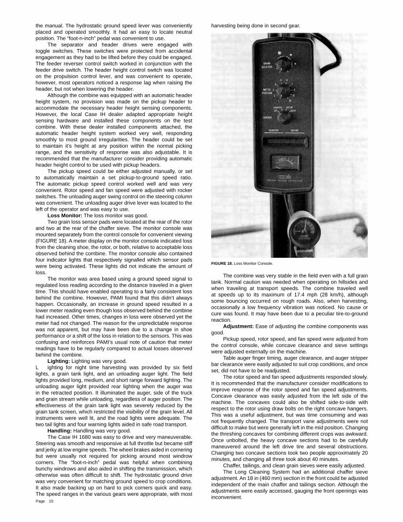
FIGURE 16. View of Incoming Windrow. Instruments: Instrumentation was good. Most of the instruments were located to the right of operator (FIGURE 17) and in the upper right corner of the cab. The instrument panel to the operator’s right contained gauges for engine oil pressure, coolant temperature, battery voltage, fuel level, and engine hours. It also contained an alarm and warning lamps for low engine oil pressure, low coolant level, excessive coolant temperature, alternator malfunction, and parking brake engagement. A digital display selectively showed engine, fan, rotor and ground speed. A separate continuous readout for engine speed would have been useful. The instrument panel in the upper right corner had warning lamps and an alarm for reduced speed of the clean grain elevator, tailings elevator, cleaning fan, feeder, rotor, rear beater, spreaders, shoe shake, and rotary air screen. The alarm set points for the rotor and fan were adjustable. The warning lamps for shaft speed reductions worked well, but were inconvenient to observe while harvesting. This was annoying when momentary slow downs in shaft speeds occurred. Although the alarm sounded, the warning lamps often did not stay illuminated long enough for the operator to see which alarm had triggered. A fl ashing warning to show which alarm warning had sounded would have been helpful. Controls: The Case IH 1680 controls were good. Most of the controls were located to the right of the operator (FIGURE 17), a few to the left, and the rest on the steering column. Most of the controls were conveniently placed and easy to use. Although clearly marked they were hard to identify at a glance. A neutral start system prevented the engine from cranking unless the separator switch was shut off and the “foot-n-inch” pedal was depressed. Fuel shut off was integrated into the throttle control lever. The gear shift was located to the left of the operator. Shifting at times was diffi cult; however, it was made easier if the hydrostatic lever was not in neutral and the “foot-n-inch” pedal was used like a clutch.
FIGURE 17. Right Side Instrument and Control Console.
The park brake was activated using the left brake pedal and the lock located to the operator’s left. Its use was not self evident and the operator had to be familiar with the procedure outlined in
Page 10
the manual. The hydrostatic ground speed lever was conveniently placed and operated smoothly. It had an easy to locate neutral position. The “foot-n-inch” pedal was convenient to use. The separator and header drives were engaged with toggle switches. These switches were protected from accidental engagement as they had to be lifted before they could be engaged. The feeder reverser control switch worked in conjunction with the feeder drive switch. The header height control switch was located on the propulsion control lever, and was convenient to operate, however, most operators noticed a response lag when raising the header, but not when lowering the header. Although the combine was equipped with an automatic header height system, no provision was made on the pickup header to accommodate the necessary header height sensing components. However, the local Case IH dealer adapted appropriate height sensing hardware and installed these components on the test combine. With these dealer installed components attached, the automatic header height system worked very well, responding smoothly to most ground irregularities. The header could be set to maintain it’s height at any position within the normal picking range, and the sensitivity of response was also adjustable. It is recommended that the manufacturer consider providing automatic header height control to be used with pickup headers. The pickup speed could be either adjusted manually, or set to automatically maintain a set pickup-to-ground speed ratio. The automatic pickup speed control worked well and was very convenient. Rotor speed and fan speed were adjusted with rocker switches. The unloading auger swing control on the steering column was convenient. The unloading auger drive lever was located to the left of the operator and was easy to use. Loss Monitor: The loss monitor was good. Two grain loss sensor pads were located at the rear of the rotor and two at the rear of the chaffer sieve. The monitor console was mounted separately from the control console for convenient viewing (FIGURE 18). A meter display on the monitor console indicated loss from the cleaning shoe, the rotor, or both, relative to acceptable loss observed behind the combine. The monitor console also contained four indicator lights that respectively signalled which sensor pads were being activated. These lights did not indicate the amount of loss. The monitor was area based using a ground speed signal to regulated loss reading according to the distance traveled in a given time. This should have enabled operating to a fairly consistent loss behind the combine. However, PAMI found that this didn’t always happen. Occasionally, an increase in ground speed resulted in a lower meter reading even though loss observed behind the combine had increased. Other times, changes in loss were observed yet the meter had not changed. The reason for the unpredictable response was not apparent, but may have been due to a change in shoe performance or a shift of the loss in relation to the sensors. This was confusing and reinforces PAMI’s usual note of caution that meter readings have to be regularly compared to actual losses observed behind the combine. Lighting: Lighting was very good. L ighting for night time harvesting was provided by six fi eld lights, a grain tank light, and an unloading auger light. The fi eld lights provided long, medium, and short range forward lighting. The unloading auger light provided rear lighting when the auger was in the retracted position. It illuminated the auger, side of the truck and grain stream while unloading, regardless of auger position. The effectiveness of the grain tank light was severely reduced by the grain tank screen, which restricted the visibility of the grain level. All instruments were well lit, and the road lights were adequate. The two tail lights and four warning lights aided in safe road transport. Handling: Handling was very good. The Case IH 1680 was easy to drive and very maneuverable. Steering was smooth and responsive at full throttle but became stiff and jerky at low engine speeds. The wheel brakes aided in cornering but were usually not required for picking around most windrow corners. The “foot-n-inch” pedal was helpful when combining bunchy windrows and also aided in shifting the transmission, which otherwise was often diffi cult to shift. The hydrostatic ground drive was very convenient for matching ground speed to crop conditions. It also made backing up on hard to pick corners quick and easy. The speed ranges in the various gears were appropriate, with most
harvesting being done in second gear.
FIGURE 18. Loss Monitor Console.
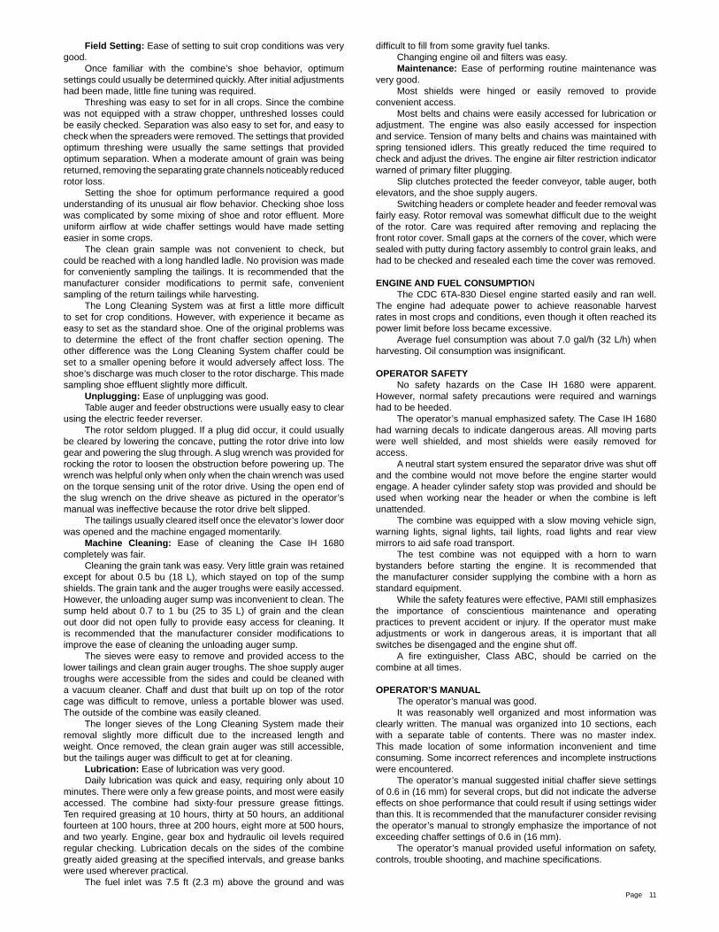
The combine was very stable in the fi eld even with a full grain tank. Normal caution was needed when operating on hillsides and when traveling at transport speeds. The combine traveled well at speeds up to its maximum of 17.4 mph (28 km/h), although some bouncing occurred on rough roads. Also, when harvesting, occasionally a low frequency vibration was noticed. No cause or cure was found. It may have been due to a peculiar tire-to-ground reaction. Adjustment: Ease of adjusting the combine components was good. Pickup speed, rotor speed, and fan speed were adjusted from the control console, while concave clearance and sieve settings were adjusted externally on the machine. Table auger fi nger timing, auger clearance, and auger stripper bar clearance were easily adjusted to suit crop conditions, and once set, did not have to be readjusted. The rotor speed and fan speed adjustments responded slowly. It is recommended that the manufacturer consider modifi cations to improve response of the rotor speed and fan speed adjustments. Concave clearance was easily adjusted from the left side of the machine. The concaves could also be shifted side-to-side with respect to the rotor using draw bolts on the right concave hangers. This was a useful adjustment, but was time consuming and was not frequently changed. The transport vane adjustments were not diffi cult to make but were generally left in the mid position. Changing the threshing concaves for combining different crops was awkward. Once unbolted, the heavy concave sections had to be carefully maneuvered around the left drive tire and several obstructions. Changing two concave sections took two people approximately 20 minutes, and changing all three took about 40 minutes. Chaffer, tailings, and clean grain sieves were easily adjusted. The Long Cleaning System had an additional chaffer sieve adjustment. An 18 in (460 mm) section in the front could be adjusted independent of the main chaffer and tailings section. Although the adjustments were easily accessed, gauging the front openings was inconvenient.
Page 11
Field Setting: Ease of setting to suit crop conditions was very good. Once familiar with the combine’s shoe behavior, optimum settings could usually be determined quickly. After initial adjustments had been made, little fi ne tuning was required. Threshing was easy to set for in all crops. Since the combine was not equipped with a straw chopper, unthreshed losses could be easily checked. Separation was also easy to set for, and easy to check when the spreaders were removed. The settings that provided optimum threshing were usually the same settings that provided optimum separation. When a moderate amount of grain was being returned, removing the separating grate channels noticeably reduced rotor loss. Setting the shoe for optimum performance required a good understanding of its unusual air fl ow behavior. Checking shoe loss was complicated by some mixing of shoe and rotor effl uent. More uniform airfl ow at wide chaffer settings would have made setting easier in some crops. The clean grain sample was not convenient to check, but could be reached with a long handled ladle. No provision was made for conveniently sampling the tailings. It is recommended that the manufacturer consider modifi cations to permit safe, convenient sampling of the return tailings while harvesting. The Long Cleaning System was at fi rst a little more diffi cult to set for crop conditions. However, with experience it became as easy to set as the standard shoe. One of the original problems was to determine the effect of the front chaffer section opening. The other difference was the Long Cleaning System chaffer could be set to a smaller opening before it would adversely affect loss. The shoe’s discharge was much closer to the rotor discharge. This made sampling shoe effl uent slightly more diffi cult. Unplugging: Ease of unplugging was good. Table auger and feeder obstructions were usually easy to clear using the electric feeder reverser. The rotor seldom plugged. If a plug did occur, it could usually be cleared by lowering the concave, putting the rotor drive into low gear and powering the slug through. A slug wrench was provided for rocking the rotor to loosen the obstruction before powering up. The wrench was helpful only when only when the chain wrench was used on the torque sensing unit of the rotor drive. Using the open end of the slug wrench on the drive sheave as pictured in the operator’s manual was ineffective because the rotor drive belt slipped. The tailings usually cleared itself once the elevator’s lower door was opened and the machine engaged momentarily. Machine Cleaning: Ease of cleaning the Case IH 1680 completely was fair. Cleaning the grain tank was easy. Very little grain was retained except for about 0.5 bu (18 L), which stayed on top of the sump shields. The grain tank and the auger troughs were easily accessed. However, the unloading auger sump was inconvenient to clean. The sump held about 0.7 to 1 bu (25 to 35 L) of grain and the clean out door did not open fully to provide easy access for cleaning. It is recommended that the manufacturer consider modifi cations to improve the ease of cleaning the unloading auger sump. The sieves were easy to remove and provided access to the lower tailings and clean grain auger troughs. The shoe supply auger troughs were accessible from the sides and could be cleaned with a vacuum cleaner. Chaff and dust that built up on top of the rotor cage was diffi cult to remove, unless a portable blower was used. The outside of the combine was easily cleaned. The longer sieves of the Long Cleaning System made their removal slightly more diffi cult due to the increased length and weight. Once removed, the clean grain auger was still accessible, but the tailings auger was diffi cult to get at for cleaning. Lubrication: Ease of lubrication was very good. Daily lubrication was quick and easy, requiring only about 10 minutes. There were only a few grease points, and most were easily accessed. The combine had sixty-four pressure grease fi ttings. Ten required greasing at 10 hours, thirty at 50 hours, an additional fourteen at 100 hours, three at 200 hours, eight more at 500 hours, and two yearly. Engine, gear box and hydraulic oil levels required regular checking. Lubrication decals on the sides of the combine greatly aided greasing at the specifi ed intervals, and grease banks were used wherever practical. The fuel inlet was 7.5 ft (2.3 m) above the ground and was
diffi cult to fi ll from some gravity fuel tanks. Changing engine oil and fi lters was easy. Maintenance: Ease of performing routine maintenance was very good. Most shields were hinged or easily removed to provide convenient access. Most belts and chains were easily accessed for lubrication or adjustment. The engine was also easily accessed for inspection and service. Tension of many belts and chains was maintained with spring tensioned idlers. This greatly reduced the time required to check and adjust the drives. The engine air fi lter restriction indicator warned of primary fi lter plugging. Slip clutches protected the feeder conveyor, table auger, both elevators, and the shoe supply augers. Switching headers or complete header and feeder removal was fairly easy. Rotor removal was somewhat diffi cult due to the weight of the rotor. Care was required after removing and replacing the front rotor cover. Small gaps at the corners of the cover, which were sealed with putty during factory assembly to control grain leaks, and had to be checked and resealed each time the cover was removed.
ENGINE AND FUEL CONSUMPTION The CDC 6TA-830 Diesel engine started easily and ran well. The engine had adequate power to achieve reasonable harvest rates in most crops and conditions, even though it often reached its power limit before loss became excessive. Average fuel consumption was about 7.0 gal/h (32 L/h) when harvesting. Oil consumption was insignifi cant.
OPERATOR SAFETY No safety hazards on the Case IH 1680 were apparent. However, normal safety precautions were required and warnings had to be heeded. The operator’s manual emphasized safety. The Case IH 1680 had warning decals to indicate dangerous areas. All moving parts were well shielded, and most shields were easily removed for access. A neutral start system ensured the separator drive was shut off and the combine would not move before the engine starter would engage. A header cylinder safety stop was provided and should be used when working near the header or when the combine is left unattended. The combine was equipped with a slow moving vehicle sign, warning lights, signal lights, tail lights, road lights and rear view mirrors to aid safe road transport. The test combine was not equipped with a horn to warn bystanders before starting the engine. It is recommended that the manufacturer consider supplying the combine with a horn as standard equipment. While the safety features were effective, PAMI still emphasizes the importance of conscientious maintenance and operating practices to prevent accident or injury. If the operator must make adjustments or work in dangerous areas, it is important that all switches be disengaged and the engine shut off. A fi re extinguisher, Class ABC, should be carried on the combine at all times.
OPERATOR’S MANUAL The operator’s manual was good. It was reasonably well organized and most information was clearly written. The manual was organized into 10 sections, each with a separate table of contents. There was no master index. This made location of some information inconvenient and time consuming. Some incorrect references and incomplete instructions were encountered. The operator’s manual suggested initial chaffer sieve settings of 0.6 in (16 mm) for several crops, but did not indicate the adverse effects on shoe performance that could result if using settings wider than this. It is recommended that the manufacturer consider revising the operator’s manual to strongly emphasize the importance of not exceeding chaffer settings of 0.6 in (16 mm). The operator’s manual provided useful information on safety, controls, trouble shooting, and machine specifi cations.

Page 12
MECHANICAL HISTORY The intent of the test was evaluation of functional performance. Extended durability testing was not conducted. However, TABLE 7 outlines the mechanical history of the Case IH1680 for the 113 hours of operation during which about 1040 ac (421 ha) of crop were harvested.
TABLE 7. Mechanical History
ItemOperating
Hours
Field Area
ac (ha)
A loose fi tting on the fuel injection pump allowed fuel to leak into the engine compartment. The fi tting was tightened and the leak stopped atThe throttle cable sheath pulled out of the cable end housing due to an incomplete crimp atA feeder slat was bent when a rock was taken in atThe clean grain elevator drive chain came off atCoolant leaks developed at two clamped hose connections on the engine. The clamps were tightened at
–
–
–––
23
4072
82, 111
101
210
376656
735, 1010
929
(85)
(152)(265)
(297, 409)
(376)
Excessive wear was found in the intake cone of the rotor cage adjacent to several welded seams at
–The end of the test
Wear of Intake Cone: At the end of the test, excessive wear was observed adjacent to several welded seams on the inner surface of the rotor intake cone assembly. Some of the steel was worn to less than half its original thickness. It is recommended that the manufacturer consider modifi cations to reduce wear in the rotor intake cone.
APPENDIX ISPECIFICATIONS
MAKE: Case IH Self-Propelled CombineMODEL: 1680 Axial FlowSERIAL NUMBER: header - JJC0051625 body - JJC0045932MANUFACTURER: J.I. Case Company 700 State Street Racine, Wisconsin 53404 U.S.A.
WINDROW PICKUP:-- make Case IH-- type rubber draper-- pickup width 13 ft (3.9 m)-- number of belts 7-- type of teeth plastic-- number of rollers 2-- height control castoring gage wheels-- drive hydraulic-- speed control electric over hydraulic-- speed range 0 to 420 ft/min (0 to 2.13 m/s)
HEADER:-- type center feed-- table width 13 ft (3.9 m) - optional-- feeder house width 45.2 in (1.1 m)-- auger diameter 22.4 in (570 mm)-- feeder conveyor 2 roller chains, undershot slatted conveyor-- conveyor speed 500 ft/min (2.5 m/s)-- range of picking height -37 to +45 in (-943 to +1140 mm)-- number of lift cylinders 3, with hydraulic accumulator - optional-- raising time 6.2 seconds-- lowering time adjustable
STONE PROTECTION:-- type sump with powered 3-wing beater-- ejection manually operated access door-- options rock trap fi nger grate, serrated beater blade extensions, stone retarder drum with no rock trap
ROTOR:-- number of rotors 1-- type longitudinally mounted, closed tube with 4 intake impeller blades multiple longitudinal and helical rasp bars, and 4 longitudinal separating fi ns-- diameter
- tube 25.6 in (649 mm)- feeding 39.2 in (996 mm)- threshing 30.7 in (779 mm)- separating 30.3 in (769 mm)
--length- feeding 20.1 in (510 mm)- threshing 43.2 in (1098 mm)- separating 46.1 in (1171 mm) - Total 109.4 in (2780 mm)
-- drive variable pitch belt through 2 – speed gearbox, torque sensitive tensioning-- speed range
- low 255 to 695 rpm- high 408 to 1082 rpm
-- options specialty rotor
CONCAVE (THRESHING):-- number 3-- type bar and wire-- number of bars 30 for each concave-- confi guration
- narrow space 28 intervals with 0.2 in (4.5 mm) wires and 0.26 in (6.5 mm) spaces- wide space 28 intervals with 0.25 in (6.4 mm) wires and 0.57 in (14.5 mm) spaces
-- area Wide Narrow- concave total 1675 in² (1.08 m²) 1675 in² (1.08 m²)- concave open area 920 in² (0.59 m²) 698 in² (0.45 m²)- open area % 55% 42%-- wrap 150 degrees-- grain delivery to shoe 5 auger conveyors-- options concave fi ller bars
CONCAVE (SEPARATING):-- number 3, plus perforated upper cage-- type perforated formed metal-- area total 2782 in² (1.80 m²)-- open area 1094 in² (0.71 m²)-- open area % 39 %-- wrap 266 degrees-- grain delivery to shoe 5 auger conveyors-- options square bar grates, solid grates
THRESHING AND SEPARATING CHAMBER:-- number of spirals 12-- pitch of spirals adjustable 11 to 33 degrees, normal position 22 degrees

Page 13
DISCHARGE BEATER:-- type 3 - wing beater-- speed 816 rpm-- standard equipment straw chopper
SHOE:-- type opposed action-- speed 280 cpm-- chaffer sieve and tailings sieve
- type adjustable louver, regular tooth- louver spacing 1.1 in (29 mm) hinge to hinge, 0.9 in (22 mm) teeth- area total 3379 in² (2.18 m²), tailings 609 in² (0.39 m²)- travel 0.6 in (15 mm) vertical, 2.2 in (57 mm) horizontal
-- cleaning sieve- type adjustable louver, regular tooth- louver spacing 1.1 in (29 mm) hinge to hinge, 0.6 in (16 mm) teeth- area 2775 in² (1.79 m²)- travel 0.6 in (15 mm) vertical, 1.3 in (32 mm) horizontal
-- options grain pan side hill dividers, alfalfa package, peterson sieve
CLEANING FAN:-- type six blade undershot-- diameter 23.2 in (590 mm)-- width 48.8 in (1240 mm)-- drive electrically controlled variable pitch belt-- speed range 428 rpm to 1148 rpm-- options slow speed fan kit
ELEVATORS:-- type roller chain with rubber fl ights-- clean grain (top drive) 8 x 11.3 in (204 x 288 mm)-- tailings (top drive) 6 x 7.9 in (153 x 200 mm)-- options steel fl ights, perforated auger troughs and elevator doors
GRAIN TANK:-- capacity 215 bu (7.8 m³)-- unloading time 123 seconds-- unloading auger diameter 12 in (300 mm)-- unloading auger length 17.3 ft (5.5 m) - optional-- standard equipment 14.3 ft (4.3 m) auger-- options perforated unloading auger tube
STRAW SPREADER:-- number of spreaders 2-- type steel disk with 6 rubber bats-- speed 278 rpm
ENGINE:-- make CDC-- model CDC 6TA-830-- type 4 stroke, turbo charged, after cooled-- number of cylinders 6-- displacement 504.5 in³ (8.3 L)-- governed speed (full throttle) 2620 rpm-- manufacturers rating 235 hp (175 kW)-- fuel tank capacity 92.3 Imp gal (420 L)
CLUTCHES:-- header electro-hydraulic-- separator electro-hydraulic-- unloader mechanical-- traction drive hydraulic valve (foot-n-inch pedal)
NUMBER OF CHAIN DRIVES: 7
NUMBER OF BELT DRIVES: 11
NUMBER OF GEARBOXES: 2
LUBRICATION POINTS:-- 10 hours 10-- 50 hours 30-- 100 hours 14-- 200 hours 3-- 500 hours 8-- yearly 2
TIRES:-- front 30.5 L - 32 R-1-- rear 14.9 - 24 R-1
OVERALL DIMENSIONS:-- wheel tread (front) 11.1 ft (3.4 m)-- wheel tread (rear) 8.9 ff (2.7 m)-- wheel base 11.5 ft (3.5 m)-- transport height 13.8 ft (4.2 m)-- transport length 33.9 ft (10.3 m)-- transport width 16.7ft (5.1 m)-- fi eld height 13.8 ft (4.2 m)-- fi eld length 33.9 ft (10.3 m)-- unloader discharge height 13.9 ft (4.2 m)-- unloader reach 13.3 ft (4.0 m)-- unloader clearance 13.7 ft (4.2 m)-- turning radius
- left 22.0 ft (6.7 m)- right 21.6 ft (6.59 m)
WEIGHT:- right front wheel 9090 lb (4125 kg)- left front wheel 9730 lb (4415 kg)- right rear wheel 3350 lb (1550 kg)- left rear wheel 3350 lb (1520 kg) TOTAL 25520 lb (11575 kg)
Page 14
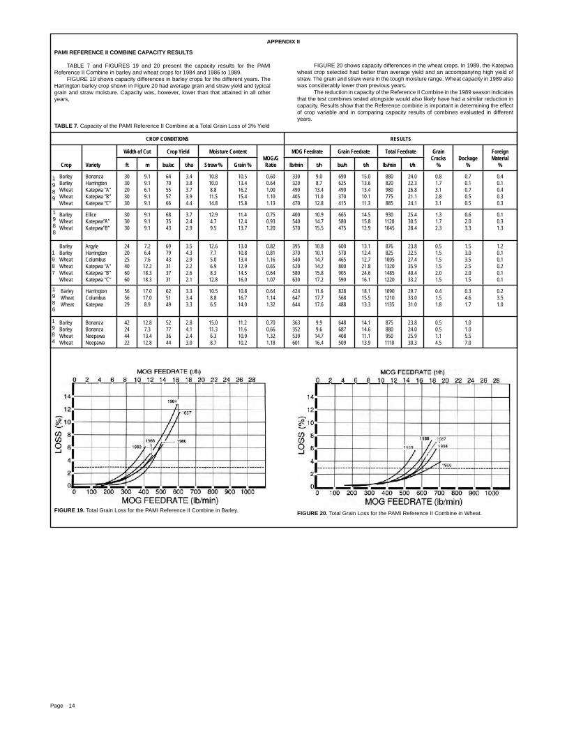
PAMI REFERENCE II COMBINE CAPACITY RESULTS
TABLE 7 and FIGURES 19 and 20 present the capacity results for the PAMI Reference II Combine in barley and wheat crops for 1984 and 1986 to 1989. FIGURE 19 shows capacity differences in barley crops for the different years. The Harrington barley crop shown in Figure 20 had average grain and straw yield and typical grain and straw moisture. Capacity was, however, lower than that attained in all other years,
TABLE 7. Capacity of the PAMI Reference II Combine at a Total Grain Loss of 3% Yield
CROP CONDITIONS RESULTS
Crop Variety
Width of Cut Crop Yield Moisture ContentMOG/GRatio
MOG Feedrate Grain Feedrate Total Feedrate GrainCracks
%Dockage
%
ForeignMaterial
%ft m bu/ac t/ha Straw % Grain % lb/min t/h bu/h t/h lb/min t/h
Barley Barley Wheat Wheat Wheat
BonanzaHarringtonKatepwa ”A”Katepwa ”B”Katepwa ”C”
3030203030
9.19.16.19.19.1
6470555766
3.43.83.73.94.4
10.810.08.811.514.8
10.513.416.215.415.8
0.600.641.001.101.13
330320490405470
9.08.7
13.411.012.8
690625490370415
15.013.613.410.111.3
880820980775885
24.022.326.821.124.1
0.81.73.12.83.1
0.70.10.70.50.5
0.40.10.40.30.3
Barley Wheat Wheat
ElliceKatepwa”A”Katepwa”B”
303030
9.19.19.1
683543
3.72.42.9
12.94.79.5
11.412.413.7
0.750.931.20
400540570
10.914.715.5
665580475
14.515.812.9
93011201045
25.430.528.4
1.31.72.3
0.62.03.3
0.10.31.3
Barley Barley Wheat Wheat Wheat Wheat
ArgyleHarringtonColumbusKatepwa ”A”Katepwa ”B”Katepwa ”C”
242025406060
7.26.47.612.218.318.3
697943313731
3.54.32.92.22.62.1
12.67.75.06.98.312.8
13.010.813.412.914.516.0
0.820.811.160.650.641.07
395370540520580630
10.810.114.714.215.817.2
600570465800905590
13.112.412.721.824.616.1
876825
1005132014851220
23.822.527.435.940.433.2
0.51.51.51.52.01.5
1.53.03.52.52.01.5
1.20.10.10.20.10.1
Barley Wheat Wheat
HarringtonColumbusKatepwa
565629
17.017.08.9
625149
3.33.43.3
10.58.86.5
10.816.714.0
0.641.141.32
424647644
11.617.717.6
828568488
18.115.513.3
109012101135
29.733.031.0
0.41.51.8
0.34.61.7
0.23.51.0
Barley Barley Wheat Wheat
BonanzaBonanzaNeepawaNeepawa
42244422
12.87.313.412.8
52773644
2.84.12.43.0
15.011.36.38.7
11.211.610.910.2
0.700.661.321.18
363352539601
9.99.6
14.716.4
648687408509
14.114.611.113.9
8758809501110
23.824.025.930.3
0.50.51.14.5
1.01.05.57.0
FIGURE 19. Total Grain Loss for the PAMI Reference II Combine in Barley.
FIGURE 20 shows capacity differences in the wheat crops. In 1989, the Katepwa wheat crop selected had better than average yield and an accompanying high yield of straw. The grain and straw were in the tough moisture range. Wheat capacity in 1989 also was considerably lower than previous years. The reduction in capacity of the Reference II Combine in the 1989 season indicates that the test combines tested alongside would also likely have had a similar reduction in capacity. Results show that the Reference combine is important in determining the effect of crop variable and in comparing capacity results of combines evaluated in different years.
FIGURE 20. Total Grain Loss for the PAMI Reference II Combine in Wheat.
APPENDIX II
1987
1986
1984
1988
1989

Page 15
TABLE 8. Regression Equations
Crop - Variety Figure Number Regression Equations Simple Correlation Coeffi cient Variance Ratio Sample Size
Barley - Harrington 4 U = -0.04 + 6.67 x 10⁻⁷ x F2
S = 0.18 + 1.39 x 10⁻²⁵ x F9
R = -0.02 + 4.63 x 10⁻⁹ x F3
0.920.990.89
28.262
799.782
19.2327
Barley - Harrington 5 U = 0.05 + 1.96 x 10⁻¹⁵ x F5
lnS = -1.75 + 1.38 x 10⁻³ x F R = 0.48 + 7.19 x 10⁻²³ x F8
0.830.210.93
25.112
1.3570.272
7
Wheat - Katepwa 6 U = 0.11 + 7.201 x 10⁻¹⁰ x F3
S = 0.24 + 1.02 x 10⁻¹⁵ x F5
R = 0.12 + 4.35 x 10⁻¹² x F3
0.930.800.93
26.262
7.292
26.7627
Wheat - Katepwa 7lnU = -4.90 + 6.76 x 10⁻³ x F S = -0.07 + 7.50 x 10⁻⁴ x F R = 0.05 + 4.394 x 10⁻⁹ x F3
0.930.480.94
41.702
2.1248.972
9
1Signifi cant at P O 0.05 2Signifi cant at P O 0.01
APPENDIX IV MACHINE RATINGS
The following rating scale is used in PAMI Evaluation Reports: Excellent Fair Very Good Poor Good Unsatisfactory
APPENDIX III REGRESSION EQUATIONS FOR CASE-IH 1680 CAPACITY RESULTS
Regression equations for the capacity results shown in FIGURES 2 to 4 are presented in TABLE 8. In the regressions, U = unthreshed loss in percent of yield, S = shoe loss in percent of yield, R = rotor loss in percent of yield, F = the MOG feedrate in lb/rain, while ln is the natural logarithm. Sample size refers to the number of loss collections. Limits of the regressions may be obtained from FIGURES 2 to 4 while crop conditions are presented in TABLE 3.
3000 College Drive SouthLethbridge, Alberta, Canada T1K 1L6Telephone: (403) 329-1212FAX: (403) 329-5562http://www.agric.gov.ab.ca/navigation/engineering/afmrc/index.html
Prairie Agricultural Machinery InstituteHead Offi ce: P.O. Box 1900, Humboldt, Saskatchewan, Canada S0K 2A0
Telephone: (306) 682-2555
Test Stations:P.O. Box 1060 P.O. Box 1150Portage la Prairie, Manitoba, Canada R1N 3C5 Humboldt, Saskatchewan, Canada S0K 2A0Telephone: (204) 239-5445 Telephone: (306) 682-5033Fax: (204) 239-7124 Fax: (306) 682-5080
This report is published under the authority of the minister of Agriculture for the Provinces of Alberta, Saskatchewan and Manitoba and may not be reproduced in whole or in part without the priorapproval of the Alberta Farm Machinery Research Centre or The Prairie Agricultural Machinery Institute.
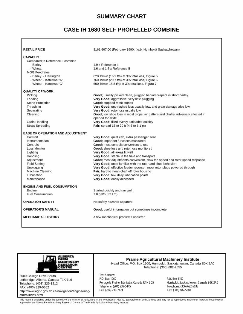
SUMMARY CHART
CASE IH 1680 SELF PROPELLED COMBINE
RETAIL PRICE $161,667.00 (February 1990, f.o.b. Humboldt Saskatchewan)
CAPACITY Compared to Reference II combine
- Barley 1.9 x Reference II - Wheat 1.6 and 1.5 x Reference II
MOG Feedrates - Barley - Harrington 620 lb/min (16.9 t/h) at 3% total loss, Figure 5 - Wheat - Katepwa “A” 760 lb/min (20.7 t/h) at 3% total loss, Figure 6 - Wheat - Katepwa “C” 690 lb/min 18.8 t/h) at 3% total loss, Figure 7
QUALITY OF WORK Picking Good; usually picked clean, plugged behind drapers in short barley Feeding Very Good; aggressive; very little plugging Stone Protection Good; stopped most stones Threshing Very Good; unthreshed loss usually low, and grain damage also low Separating Very Good; rotor loss usually low Cleaning Good; low shoe loss in most crops; air pattern and chaffer adversely effected if opened too wide Grain Handling Very Good; fi lled evenly, unloaded quickly Straw Spreading Fair; spread 15 to 20 ft (4.6 to 6.1 m)
EASE OF OPERATION AND ADJUSTMENT Comfort Very Good; quiet cab, extra passenger seat Instrumentation Good; important functions monitored Controls Good; most controls convenient to use Loss Monitor Good; shoe loss and rotor loss monitored Lighting Very Good; all areas lit well Handling Very Good; stable in the fi eld and transport Adjustment Good; most adjustments convenient, slow fan speed and rotor speed response Field Setting Very Good; once familiar with the rotor and shoe behavior Unplugging Very Good; effective feeder reverser; most rotor plugs powered through Machine Cleaning Fair; hard to clean chaff off rotor housing Lubrication Very Good; few daily lubrication points Maintenance Very Good; easily accessed
ENGINE AND FUEL CONSUMPTION Engine Started quickly and ran well Fuel Consumption 7.0 gal/h (32 L/h)
OPERATOR SAFETY No safety hazards apparent
OPERATOR’S MANUAL Good; useful information but sometimes incomplete
MECHANICAL HISTORY A few mechanical problems occurred