Modeling Failure of 3D Fiber Reinforced Foam Core Sandwich ...

Evaluation on Failure of Fiber-Reinforced SandZhiwei Gao1 and Jidong Zhao2
Abstract: Fiber reinforcement can help to enhance soil strength, stabilize near-surface soil layers, and mitigate the risk of soil liquefaction.Evaluation of the strength of fiber-reinforced soils needs a proper failure criterion. This study presents a three-dimensional failure criterion forfiber-reinforced sand. By assuming that the total strength of the composite is a combination of the shear resistance of the host soil and thereinforcement of fibers, a general anisotropic failure criterion is proposed with special emphasis on the effect of isotropically/anisotropicallydistributed fibers. An anisotropic variable, defined by the joint invariant of the deviatoric stress tensor and a deviatoric fiber distribution tensor,is introduced in the criterion to quantify the fiber orientation with respect to the strain rate/stress direction at failure.With further considerationof the fiber concentration and other factors such as aspect ratio, the proposed criterion is applied to predicting the failure of fiber-reinforcedsand in conventional triaxial compression/extension tests for both isotropically and anisotropically distributed fiber cases. The predictionsare in good agreement with the test results available in the literature. The practical significance of using this criterion for such problems asinclined slope stabilization is briefly discussed.DOI: 10.1061/(ASCE)GT.1943-5606.0000737.© 2013 American Society of Civil Engineers.
CE Database subject headings: Fiber reinforced materials; Failures; Anisotropy; Triaxial tests; Slope stability; Sand (soil type).
Author keywords: Fiber-reinforced soil; Failure criterion; Anisotropy; Fiber distribution tensor; True triaxial tests; Slope stabilization.
Introduction
Earth reinforcement has become routine in geotechnical engineeringto enhance the bearing capacity of geostructures such as airfields,foundations, embankments, and pavement roads built on soft soils,and to stabilize engineered soil slopes and loosely filled retainingwalls. Using fibers ranging from steel bars, polypropylene, poly-ester, glass fibers, and biodegradable fibers such as coir and jute,has been proven to be particularly effective for soil reinforcement(Santoni andWebster 2001; Liu et al. 2011). Some recent initiativesalso use waste materials such as tire shred, waste fishing nets, andwaster plastics as reinforcing fibers (Zornberg et al. 2004; Kim et al.2008). Use of fiber reinforcement for soil improvement has beeninspired by observations on the stabilizing effect of root systems tosoils (Wu et al. 1979; Gray and Sotir 1995; Sonnenberg et al. 2010).Generally, the high tensile strength and extendibility of the addedfibers help to effectively reduce the compressibility and brittleness ofthe host soil, which is generally superior to traditional soil improve-ment approaches such as using cement (Park 2011). Meanwhile, thereinforcing fibers can be placed either randomly tomaintain strengthisotropy or in a desired direction to provide optimal reinforcement.
The reliable design of fiber-reinforced soil structures requires athorough understanding on the reinforcing mechanics and failuremechanisms. In particular, good prediction of the strength of thereinforced soil is of pivotal importance. Toward these goals, bothlaboratory tests and numerical simulations have been carried out.
Among the various experimental means, direct shear tests have beenwidely employed to simulate the pullout failure of fibers/roots alonga shear bandelike failure plane (Athanasopoulos 1996; Liu et al.2009; Sadek et al. 2010). Meanwhile, being a proven way to exploresoil behavior under a wide range of confining pressure, triaxialcompression tests have been frequently used for the study of fiber-reinforced soils (Gray and Al-Refeai 1986; Consoli et al. 2007b).Unconfined compression tests have also been employed to ex-amine the strength of fiber-reinforced soil without lateral support(Kaniraj and Havanagi 2001). Numerical studies have also beencarried out to investigate the behavior of fiber-reinforced soils(Sivakumar Babu et al. 2008). In general, the various approacheshave shown thatfiber inclusion can increase the peak strength aswellas ductility of soil through the stretching of fibers and the mobili-zation of friction between the soil particles and fibers. A number offactors have been identified to be closely related to the efficiency ofreinforcement, such as the fiber properties (length, density, aspectratio, extendibility, and degradability of fiber), soil properties (gra-dation, particle size, shape, and density), effective confinement, andstrain levels (Heineck et al. 2005;Consoli et al. 2007a; Liu et al. 2011).
A particularly distinct feature found infiber-reinforced soils is theanisotropic behavior they may demonstrate under various loadingconditions. This was first revealed by direct shear tests in whichthe measured strength of a fiber-reinforced soil was found to be de-pendent on the fiber orientation in the composite (Gray and Ohashi1983; Jewell andWroth 1987; Palmeira andMilligan 1989).Morerecent studies using triaxial compression and extension tests withvarying fiber orientations have repeatedly supported the aforemen-tioned observations (Li 2005; Diambra et al. 2010; Ibraim et al.2010). For instance, Diambra et al. (2010) have shown that the con-tribution of fibers to soil strength is remarkable in triaxial compressionbut limited in triaxial extension, and have indicated that it is attrib-utable to the preferred orientation of fibers in the tested samples(Diambra et al. 2007). The majority of fibers that align to the hori-zontal direction will experience tension in triaxial compression andcan contribute considerably to the strength of the composite, whereasthose fibers will mostly be subjected to compression under triaxialextension and therefore cannot fully unleash their enhancement to
1Ph.D. Candidate, Dept. of Civil and Environmental Engineering, HongKong Univ. of Science and Technology, Clear Water Bay, Kowloon, HongKong SAR, China.
2Assistant Professor, Dept. of Civil and Environmental Engineering,Hong Kong Univ. of Science and Technology, Hong Kong SAR, China(corresponding author). E-mail: [email protected]
Note. This manuscript was submitted on September 13, 2011; approvedonMarch 20, 2012; published online onMarch 22, 2012. Discussion periodopen until June 1, 2013; separate discussions must be submitted forindividual papers. This paper is part of the Journal of Geotechnical andGeoenvironmental Engineering, Vol. 139, No. 1, January 1, 2013. ©ASCE,ISSN 1090-0241/2013/1-95e106/$25.00.
JOURNAL OF GEOTECHNICAL AND GEOENVIRONMENTAL ENGINEERING © ASCE / JANUARY 2013 / 95
J. Geotech. Geoenviron. Eng. 2013.139:95-106.
Dow
nloa
ded
from
asc
elib
rary
.org
by
Hon
g K
ong
Uni
v O
f Sc
ienc
e &
on
01/1
2/13
. Cop
yrig
ht A
SCE
. For
per
sona
l use
onl
y; a
ll ri
ghts
res
erve
d.

the composite strength (Michalowski and �Cermák2002;Michalowski2008; Diambra et al. 2010).
In modeling the failure of fiber-reinforced soils, traditionalapproaches assume that the fiber orientation in the soil is random(Maher and Gray 1990; Zornberg 2002; Michalowski and Zhao1996;Michalowski and �Cermák 2003; Ranjan et al. 1996), while thereal shear behavior of fiber-reinforced soil depends typically on theloading direction largely as a result of anisotropic fiber orientation.Traditional models apparently lead to inadequate characterization ofthe soil behavior. Recently, there have been a number of further im-provements in this regard. For example, Michalowski and �Cermák(2002) have employed a fiber distribution function to characterizethe fiber orientation anisotropy and, hence, the anisotropic strengthof the composite soil. The same approach has recently been employedby Diambra et al. (2010) in conjunction with the theory of mixture tomodel the strength and deformation anisotropy of fiber-reinforcedsand. However, these latest developments have been limited to casesof plane strain or triaxial compression/extension conditions only,andmay have difficulty in describing the failure of the composite soilunder general three-dimensional (3D) loading conditions (e.g., theeffect of both the intermediate principal stress magnitude and fiberdistribution anisotropy). It is desirable to develop a general 3D failurecriterion to describe the anisotropic strength of fiber-reinforced soils,which will be pursued in this paper. By assuming the compositestrength is jointly contributed by the host soil and the fiber rein-forcement, a failure criterion for the isotropic case offiber distributionis formulated first. It will then be generalized to account for thestrength anisotropy caused by the anisotropic fiber distribution. Indoing so, a pivotal step is the introduction of an anisotropic variable,A, expressed by a joint invariant of the deviatoric stress tensor andthe deviatoric fiber orientation tensor. This joint invariant enablesdescribing the orientation of the fiber concentration with respect tothe strain rate/stress direction at failure. A comparison between thepredictions by the criterion and testing data in triaxial compressionand extension ismade, and their practical usefulness for geotechnicalengineering problems is discussed.
Fiber Distribution Tensor and Anisotropic Variable
Fiber Distribution Tensor
Under external load, soil particles and fibers can form anisotropicinternal structures that dictate the macroscopic deformation andfailure of the composite soil. Inmodeling the anisotropic behavior offiber-reinforced soil, it is of cardinal importance to choose a suitablequantity to characterize the internal structure. Generally, the internalstructure depends on both the fabric structure of the host soil and thedistribution of fibers. Recent experimental observations suggest thatthe anisotropic behavior of fiber-reinforced soil is dominated by thefiber orientation rather than by the host soil (Michalowski and �Cermák2002; Diambra et al. 2010). Hence, appropriate characterization ofthe fiber distribution becomes important, in whichmany past studieshave employed a (scalar) function (Michalowski and �Cermák 2002;Michalowski 2008; Diambra et al. 2010). However, a scalar descrip-tionmay not be adequate to characterize the spatial distribution ofreinforcingfibers in the soil.Amoregeneral and robustway todescribethe anisotropic behavior offiber-reinforced soil in the 3D stress spacewould be tensor based. Indeed, fabric tensors have been widelyemployed to characterize the anisotropic internal structure comprisedof particle contacts and void distribution in sand (Oda et al. 1985),and have also been used in themodeling of failure and deformation ofgeomaterials (Li and Dafalias 2002; Gao et al. 2010). In line withthese studies, the following symmetric second-order tensor Fij to
quantify the fiber distribution in a fiber-reinforced soil will be used(Oda et al. 1985):
Fij ¼ 1V
ðV
rðnÞninj dV ð1Þ
where V 5 total volume of a representative volume element of thecomposite (see Fig. 1), ni 5 ith component of the unit vector aligningin direction n, and rðnÞ5 fiber concentration (ratio of fiber volumeto composite volume) in direction n (Michalowski and �Cermák2002). Ideally, rðnÞ shouldbedeterminedon a statistical basiswithinthe representative element. Quite often, in both laboratory and en-gineering practice, the preparation techniques or the constructionmethods used lead to a distribution of fiber that can be largelyregarded as cross anisotropic. In this case, a simplified fiber dis-tribution function rðzÞ proposed by Michalowski and �Cermák(2002) and used subsequently by Diambra et al. (2007) to charac-terize the fiber concentration may further be employed. Here, z is theangle of fiber inclination to the preferred fiber orientation plane (e.g.,the x-y plane in Fig. 1). Importantly, both rðzÞ and rðnÞ have tosatisfy the following requirement (Michalowski and �Cermák 2002):
r ¼ 1V
ðV
rðnÞ dV ¼ 1V
ðV
rðzÞ dV ¼ Vf
Vð2Þ
where r 5 average fiber concentration and Vf 5 total volume offibers in the entire representative volume element shown in Fig. 1.The fiber concentration can also be described by the ratio betweenthe weight of the fibers and that of the total composite soil (Maherand Gray 1990).
Fiber distribution tensor Fij defined in Eq. (1) can always bedecomposed into isotropic and deviatoric parts as follows:
Fij ¼ 13r�dij þ dij
� ð3Þ
where dij 5 deviatoric fiber distribution tensor, which containsinformation about the 3Ddistribution offibers and the correspondingdegree of anisotropy, and dij5Kronecker delta (where dij 5 1 fori 5 j and dij 5 0 for i� j). As noticed by Diambra et al. (2007), themoist tamping method that is frequently used in sample preparationin the laboratory typically produces a cross-anisotropic fiber dis-tribution. Because the rolling and compaction processes are usuallyone-dimensional in engineering practice, a cross-anisotropic fabricdistribution is also expected (Michalowski 2008). In doing so, it isassumed that the principal axes of fiber distribution tensor Fij arealigned with the reference coordinate system ðx; y; zÞ, with the x-y
Fig. 1. Spherical representative volume element for fiber-reinforcedsoils (adapted from Michalowski and �Cermák 2002)
96 / JOURNAL OF GEOTECHNICAL AND GEOENVIRONMENTAL ENGINEERING © ASCE / JANUARY 2013
J. Geotech. Geoenviron. Eng. 2013.139:95-106.
Dow
nloa
ded
from
asc
elib
rary
.org
by
Hon
g K
ong
Uni
v O
f Sc
ienc
e &
on
01/1
2/13
. Cop
yrig
ht A
SCE
. For
per
sona
l use
onl
y; a
ll ri
ghts
res
erve
d.

plane being the isotropic plane (or the preferred fiber orientation plane),and z being directed to the axis of the cross anisotropy, which is thecompacting direction. Eq. (3) can then be rewritten in the followingmatrix form:
Fij ¼24Fz 0 0
0 Fx 0
0 0 Fy
35
¼ 13r
24 1 0 0
0 1 0
0 0 1
35þ 1
3r
24 2D 0 0
0 D=2 0
0 0 D=2
35 ð4Þ
where D 5 scalar that characterizes the magnitude of the crossanisotropy. Its value ranges from22when all the fibers align in the zdirection ðFz 5 r; Fx 5 Fy 5 0Þ and 1 when there is no fiberaligning in the z direction ½Fz 5 0; Fx 5Fy 5 ð1=2Þr�. If D 5 0[Fx 5Fy 5Fz 5 ð1=3Þr ], the fiber orientation is isotropic (random)in the 3D space.
Definition of an Anisotropic Variable
Michalowski and �Cermák (2002) and Diambra et al. (2010) havefound that only the portion offibers that are subjected to tensile stresscontribute to the strength of the composite soil. To describe thisfeature, it is important that a quantity can be defined to characterizethe fiber concentration with respect to the loading direction. Thestrain rate axes direction has been employed by Michalowski and�Cermák (2002) and Diambra et al. (2010) for such a purpose.However, it is sometimes not that convenient to determine the strainrate axes direction. In contrast, the stress is an easier quantity tomeasure and a convenient variable to use for a similar purpose.Indeed, at the failure stage of soil, the strain rate has been found to belargely coaxial with the applied stress for clean sand, even though thetwo are not coaxial at the early stage of loading (Gutierrez andIshihara 2000). Although no testing results are yet available on fiber-reinforced soils in general 3D stress space, it is expected that thecoaxial response at failure also holds under more general loadingconditions, at least in an approximate sense. Based on the previousconsideration, the following stress direction lij is employed to re-place the strain rate direction in the study:
lij ¼ sijffiffiffiffiffiffiffiffiffiffiffiffiffismnsmn
p ð5Þ
where Sij ¼ sij 2 pdij 5 deviatoric part of stress tensor sij, andp5smm=3 5 mean stress. Furthermore, the following anisotropicvariable A, which is used to characterize the fiber concentration withrespect to the strain rate/loading direction at failure, is introduced:
A ¼ lijdijffiffiffiffiffiffiffiffiffiffiffidkldkl
p ð6Þ
As can be seen fromEq. (6), a greater value of A indicates that fibersare oriented more preferably in the major principal stress direction,which is positive in compression. This implies that more fibers arebeing subjected to compression, and hence the reinforcing effect ofthe fibers to the composite strength is less efficient. For the case of across-anisotropically distributed fiber with the preferred fiber orien-tation plane being horizontal, the value of A is 21 in triaxialcompression with the major principal stress being in the verticaldirection, and A5 1 in triaxial extension with the major principalstress in the horizontal direction. For other general loading conditions,A varies between21 and 1. A detailed discussion of the change of A
with loading directions with respect to the cross-anisotropy planecan be found in Gao et al. (2010). Here, A5 0 for the isotropic fiberdistribution case. Evidently, in addition to A, the degree of fiberdistribution anisotropy d5
ffiffiffiffiffiffiffiffiffiffidijdij
palso affects the strength an-
isotropy of fiber-reinforced soil and needs to be considered towarda realistic failure criterion, which will be discussed subsequently.
Failure Criteria for Fiber-Reinforced Sand
In line with previous studies (Gray and Ohashi 1983; Maher andGray 1990; Zornberg 2002; Diambra et al. 2010), it is assumed thatthe shear strength of a fiber-reinforced soil is jointly attributed to bytwo parts, one from the host soil and the other by the fiber rein-forcement. Furthermore, it is assumed that the anisotropy of the hostsoil is regarded as negligible compared with that induced by thereinforcing fibers, such that the host soil can be considered to beisotropic, while the reinforcing fibers dominate the anisotropic be-havior of the composite strength. This assumption is also consistentwith early studies byMichalowski (2008) and Diambra et al. (2010).Depending on the preparationmethod, thefibers can be distributed inthe soil isotropically or anisotropically. The isotropic fiber distri-bution case will be discussed first and then the anisotropic case willbe discussed.
Failure of Fiber-Reinforced Sand Considering theIsotropic Fiber Distribution
For a clean or cemented soil under general loading conditions, it iscommon to use the following description to characterize the soilstrength (Yao et al. 2004):
q ¼ McgðuÞ�p þ su
0
� ð7Þ
where q5ffiffiffiffiffiffiffiffiffiffiffiffiffiffiffiffi3=2sijsij
p5 deviatoric stress; Mc 5 stress ratio q=p at
failure in triaxial compression; su0 5 triaxial tensile strength of the soil
without fiber reinforcement (see Fig. 2); and gðuÞ 5 interpolationfunction characterizing the influence of the intermediatemajor principalstress magnitude on the failure of soils with u being the Lode angle
u ¼ tan21�2b2 1ffiffiffi
3p
�ð8Þ
Fig. 2. Failure curves for unreinforced soil and fiber-reinforced soil intriaxial compression
JOURNAL OF GEOTECHNICAL AND GEOENVIRONMENTAL ENGINEERING © ASCE / JANUARY 2013 / 97
J. Geotech. Geoenviron. Eng. 2013.139:95-106.
Dow
nloa
ded
from
asc
elib
rary
.org
by
Hon
g K
ong
Uni
v O
f Sc
ienc
e &
on
01/1
2/13
. Cop
yrig
ht A
SCE
. For
per
sona
l use
onl
y; a
ll ri
ghts
res
erve
d.

where b5 ðs2 2s3Þ=ðs1 2s3Þ 5 intermediate principal stressratio; s1;s2, and s3 5 major, intermediate, and minor principalstress, respectively; and gðuÞ is used to control the shape of thefailure curves of soils (assumed to be isotropic here) in the deviatoricplane. In the current study, the following expression for gðuÞ isemployed (Sheng et al. 2000):
gðuÞ ¼�
2a4
1 þ a4 þ ð12a4Þsin 3u�1=4
ð9Þ
where a 5 Me/Mc and Me 5 failure stress ratio q/p obtained intriaxial extension tests on the host soil. Evidently, with the ex-pression in Eq. (9), g(u) reaches a value of unity in triaxial com-pression and a reaches a value of unity in triaxial extension.
A failure criterion for fiber-reinforced sand can be developedbase on Eq. (7). It is desirable to have a failure criterion accountingfor the following two features under triaxial compression. (1) Asthe effective confinement (p1su
0) decreases, the failure envelope offiber-reinforced soil converges to that of the host soil. The failure ofthe composite soil has been found to be governed by slip betweensoil particles and fibers at low confining pressure (Michalowski andZhao 1996; Zornberg 2002; Consoli et al. 2007c). While the in-terface between the two is governed by frictional resistance, the fiberreinforcement will decrease with the decrease of effective confine-ment.At the extreme case of zero effective confinement (p1su
0 5 0),the strength of the composite and the fiber reinforcement will bothbecome zero. (2) The failure curve for the fiber-reinforced soilapproaches a straight line with a slope of Mc at high effective con-finement.At high effective confinement, the failure of the compositeis expected to be mainly governed by either the yielding of the fiber(strong and thick fibers) or by fiber breaking (weak or very thinfibers) (Maher and Gray 1990; Consoli et al. 2007c; Michalowski2008; Silva Dos Santos et al. 2010). In either of the two cases, thefiber reinforcement would reach a maximum/limit, which rendersthe failure envelopes for the reinforced and unreinforced soilsparallel to each other at high confining pressure.
A simple bilinear relationship has been employed by Maher andGray (1990) and Zornberg (2002) to describe the failure behavior offiber-reinforced soil, wherein the two line segments intersect witheach other at the critical confining/normal stress. Michalowski and�Cermák (2003) considered various mechanisms of work dissipationat low and high confining pressures and proposed a criterion with astraight segment when the confining stress is below the criticalconfining stress and a curved one when it is above the criticalconfining stress. In this study, the following continuous functions isproposed to characterize the failure envelopes:
q ¼ McgðuÞ�p þ su
0
� þ fc ð10aÞ
fc ¼ cpr
�12 exp
�2k
p þ su0
pr
��ð10bÞ
wherec andk 5 two nonnegativematerial constants, pr 5 referencepressure (the atmospheric pressure, patm5 101 kPa, is adopted here),and fc 5 function describing the fiber reinforcement to the compositestrength. Fig. 2 is an illustration of the failure criterion. It can beobserved that the proposed criterion satisfies the two features pre-viously mentioned. The predicted composite strength is zero at zeroeffective confinement state (p1su
0 5 0), and the failure envelopeapproaches q�Mc½ðp1su
0Þ1 cpr� when p is extremely large withk. 0. When c and/or k are zero, it leads to recovering the predictedfailure curve for fiber-reinforced sand to that of the unreinforcedsoils [Figs. 3(a and b)]. Dimensionless constant c can be used to
characterize the maximum/limit fiber reinforcement in conjunctionwith pr because the maximum value of fc is cpr according to Eq.(10b) [see also Fig. 2 and Fig. 3(a)]. Following Maher and Gray(1990) and Zornberg (2002) as well as Michalowski and �Cermák(2003), themean stress at which the failure curve reaches the straightpart will be termed the critical mean stress. The value of k controlsthe magnitude of this critical mean stress beyond which the failureof fiber-reinforced soils would be governed by either fiber yieldingor breakage because a higher value of k renders the failure curve toapproach the straight segment at a relatively lower mean stresslevel, as shown in Fig. 3(b). Both c and kmay depend on the fiberproperty, soil property, and frictional characteristics between fibersand soil.
The term accounting for the fiber-reinforcement contribution inEq. (10b), fc, has the same form as sliding function fb proposed byDiambra et al. (2010), where fb has been used by Diambra et al.(2010) to characterize the bonding efficiency between sand particlesand fibers when p5 0 and fb5 0 (full sliding); fb reaches a positivelimit value at very high confining pressure. It can be expected that thefiber reinforcement would be approximately proportional to fb aslong as the fibers are intact. Therefore, to some extent function fc can
Fig. 3. Illustration of the effect of parameters (a) c and (b) k on thecriterion predictions
98 / JOURNAL OF GEOTECHNICAL AND GEOENVIRONMENTAL ENGINEERING © ASCE / JANUARY 2013
J. Geotech. Geoenviron. Eng. 2013.139:95-106.
Dow
nloa
ded
from
asc
elib
rary
.org
by
Hon
g K
ong
Uni
v O
f Sc
ienc
e &
on
01/1
2/13
. Cop
yrig
ht A
SCE
. For
per
sona
l use
onl
y; a
ll ri
ghts
res
erve
d.

also be treated as a measure of the bonding efficiency between thesoil particles and fibers.
To verify the proposed failure criterion in Eq. (10), a comparisonwill be made between its predictions on the shear strength for fiber-reinforced sandwith randomfiber orientationunder triaxial conditionsand the test data. It is helpful to first briefly introduce the parametercalibration. ParametersMc andsu
0 can be readily calibrated accordingto the test results on the host soil without fiber. As can be seen fromFig. 2, the intersection of the dashed line (whichmerges to the straightportion of the failure curve of the fiber-reinforced soils at a highmeanstress level) with the q axis is Mcðsu
0 1 cprÞ, which can be used todetermine the value of c in conjunction with of the already knownMc
and su0. Finally, parameter k can be calibrated through trial and error.
Experience has shown that a typical value ofk in the range of 0.0e0.7is acceptable. For the triaxial compression case, g(u) 5 1.
Shown inFig. 4 are two sands reinforced by glass fiber tested byMaher and Gray (1990), the Muskegon Dune sand and mortarsand. The glass fiber concentration in both sands is around 3% byweight but with various aspect ratios (defined as the ratio betweenthe fiber length and diameter). For either case, various k have beenobtained. Nevertheless, it is found that the variation of k with thefiber aspect ratio is small, and a single value of k suits fairly wellfor either sand case. It is found that the value of c generallyincreases with the aspect ratio of the glass fiber, which is consistentwith the regressed relationship obtained by Ranjan et al. (1996). Atthe same fiber aspect ratio, the value of c is found to be greater forfiber-reinforced Muskegon Dune sand than for fiber-reinforcedmortar sand, while the k value is greater for the latter sand. Severalfactors—such as gradation, particle shape, and grain size—areattributable to the observed differences (Maher and Gray 1990).From Fig. 4 notably good agreement between the prediction by theproposed failure criterion and the testing data can be observed inboth sand cases.
The failure criterion in Eq. (10) has also been used to predict thestrength of chopped polypropylene fiber-reinforced/unreinforcednonplastic silty-sand reported by Heineck and Consoli (2004).The fiber content for this case is 0.5% by weight. The prediction andcomparison are presented in Fig. 5. Overall, the prediction agreeswell with the test data for this sand, too. Also, with a critical meanstress for this sand at a much lower 250 kPa than the previous twosands (around 500e750 kPa), the value of k for this case is greaterthan for the former two cases. This may have been caused by the useof a much smaller diameter and lower concentration of fiber in thiscase than in the previous two cases. Thefiber aspect ratio for this caseis also much higher than in the former two cases, which will yielda lower critical confining stress. This is consistent with the obser-vation by Michalowski and �Cermák (2003) as well.
Failure Criterion for Fiber-Reinforced Sand with theAnisotropic Fiber Distribution
Based on Eq. (10) and the fact that the strength anisotropy of fiber-reinforced sand is dominated by the anisotropicfiber distribution, thefollowing expression is proposed to describe the strength anisotropyof fiber-reinforced sand by assuming that the fiber reinforcementdepends on anisotropic variableA and the degree of fiber distributionanisotropy d
q ¼ McgðuÞ��
p þ su0
� þ ~cðAÞpr�12 exp
�2k
p þ su0
pr
���
ð11Þ
where
~c ¼ celdð12cAÞ ð12Þ
where l and c two positive material parameters. Essentially, eld inEq. (12) is used to quantify the degree of strength anisotropy offiber-reinforced sand. Because 21 # A # 1 and ~c$ 0 should besatisfied,c should range from zero to unity. For special caseswherefiber distribution tensor Fij can be expressed in the form of Eq. (4)andD can be readily obtained [e.g., allfibers orient in the zdirection(D522) or all fibers evenly align in the x-y plane (D5 1)], degreeof anisotropy d is known and l is a separate parameter. However,for most applications the preferred fiber distribution plane isknown a priori (A can be calculated) while d is hard to determine.Thus, the entire term eld can be treated as one parameter and can befurther calibrated against the test results with various loadingdirections. Indeed, celd can even be taken as a single parameterwhen the fiber distribution is fixed and the test data with a random(isotropic) fiber distribution are not available (e.g., c cannot beobtained). Some interesting observations can be further made fromEqs. (11) and (12):
Fig. 4. Comparison between the prediction of the proposed failurecriterion and the test results on two glass fiber-reinforced sands (fiberconcentration at 3% by weight and various aspect ratios): (a) MuskegonDune sand and (b) Mortar sand (data from Maher and Gray 1990)
JOURNAL OF GEOTECHNICAL AND GEOENVIRONMENTAL ENGINEERING © ASCE / JANUARY 2013 / 99
J. Geotech. Geoenviron. Eng. 2013.139:95-106.
Dow
nloa
ded
from
asc
elib
rary
.org
by
Hon
g K
ong
Uni
v O
f Sc
ienc
e &
on
01/1
2/13
. Cop
yrig
ht A
SCE
. For
per
sona
l use
onl
y; a
ll ri
ghts
res
erve
d.
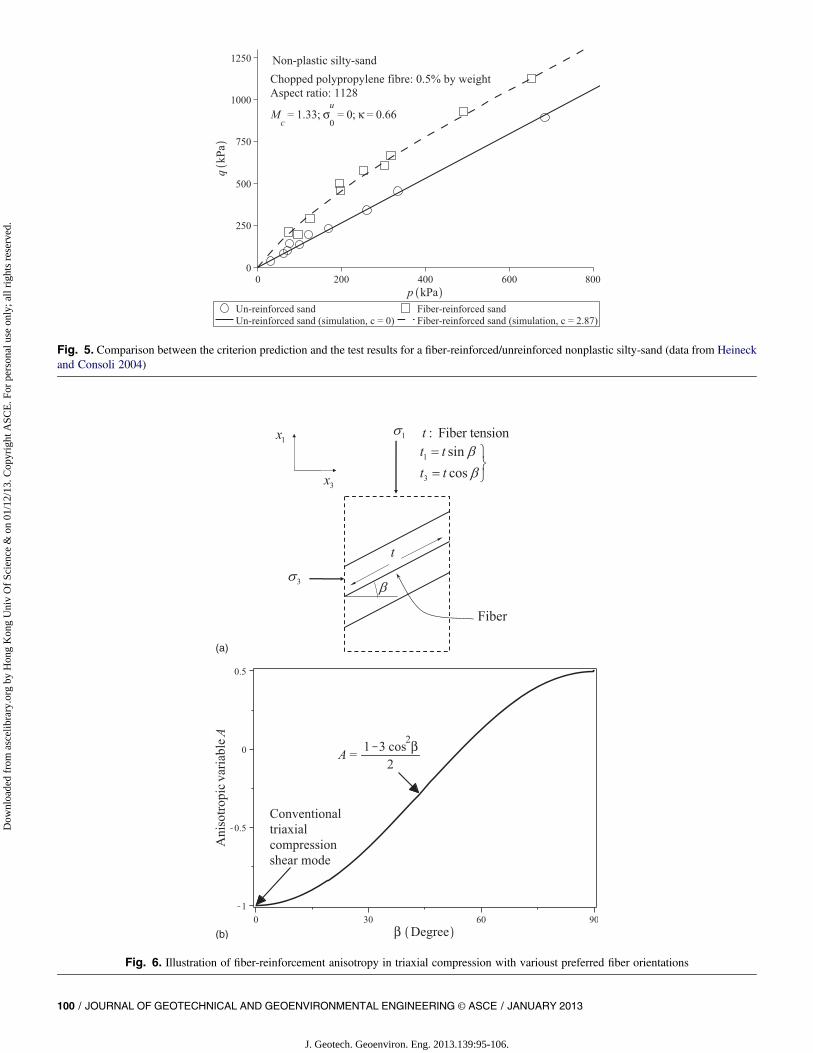
Fig. 5. Comparison between the criterion prediction and the test results for a fiber-reinforced/unreinforced nonplastic silty-sand (data from Heineckand Consoli 2004)
Fig. 6. Illustration of fiber-reinforcement anisotropy in triaxial compression with varioust preferred fiber orientations
100 / JOURNAL OF GEOTECHNICAL AND GEOENVIRONMENTAL ENGINEERING © ASCE / JANUARY 2013
J. Geotech. Geoenviron. Eng. 2013.139:95-106.
Dow
nloa
ded
from
asc
elib
rary
.org
by
Hon
g K
ong
Uni
v O
f Sc
ienc
e &
on
01/1
2/13
. Cop
yrig
ht A
SCE
. For
per
sona
l use
onl
y; a
ll ri
ghts
res
erve
d.
1. If the fiber distribution is isotropic, both d and A will becomezero. Hence, ~c5 c and Eq. (11) becomes identical to Eq. (10).The isotropic case in Eq. (10) thus represents a special case ofEq. (11).
2. When the fiber distribution is anisotropic, d . 0, ~c will varywith A. As l is typically positive, ~c also increases with thedegree of anisotropy d.
3. If the fiber distribution is fixed, when themajor principal stressdirection deviates from the axis of the preferred fiber orien-tation plane, A increases and ~c decreases. Physically, such achange implies that there will bemore fibers tending to align inthe major principal stress direction and becoming more sub-jected to compression, which essentially renders the reinforcingof fibers less effective. A simple illustration is given in Fig. 6 ofthis mechanism in triaxial compression, wherein all fibers aresupposed to orientate in onepreferredplanewith an angle ofb tothe horizontal. Evidently, only the horizontal component t3(5t cosb) of total fiber tension t contributes to the reinforce-ment by preventing lateral expansion of the sample. As can beseen from Fig. 6(b), the reinforcing effect will generally de-crease with an increasing b, or with an increasing A. Thisphenomenon has already been experimentally confirmed byMichalowski and �Cermák (2002) and Diambra et al. (2010).
4. Eq. (12) can also be used in conjunction with other isotropicfailure criteria to account for strength anisotropy. For instance, thecohesioncMCand/or the frictionanglewMC in theMohr-Coulomb(MC) failure criterion can be assumed to be functions of A andd to model the strength anisotropy of fiber-reinforced soils.
Prediction of the Strength Anisotropy forFiber-Reinforced Sand
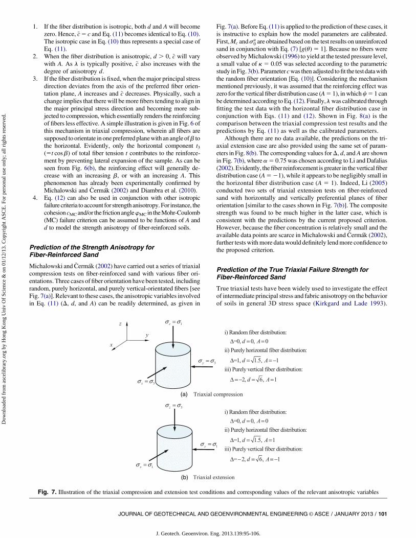
Michalowski and �Cermák (2002) have carried out a series of triaxialcompression tests on fiber-reinforced sand with various fiber ori-entations. Three cases offiber orientation have been tested, includingrandom, purely horizontal, and purely vertical-orientated fibers [seeFig. 7(a)]. Relevant to these cases, the anisotropic variables involvedin Eq. (11) (D, d, and A) can be readily determined, as given in
Fig. 7(a). Before Eq. (11) is applied to the prediction of these cases, itis instructive to explain how the model parameters are calibrated.First,Mc andsu
0 are obtained based on the test results on unreinforcedsand in conjunction with Eq. (7) [g(u)5 1]. Because no fibers wereobserved byMichalowski (1996) to yield at the tested pressure level,a small value of k 5 0.05 was selected according to the parametricstudy inFig. 3(b). Parameter cwas then adjusted tofit the test datawiththe random fiber orientation [Eq. (10)]. Considering the mechanismmentioned previously, it was assumed that the reinforcing effect waszero for the vertical fiber distribution case (A5 1), inwhichc5 1 canbe determined according toEq. (12). Finally,lwas calibrated throughfitting the test data with the horizontal fiber distribution case inconjunction with Eqs. (11) and (12). Shown in Fig. 8(a) is thecomparison between the triaxial compression test results and thepredictions by Eq. (11) as well as the calibrated parameters.
Although there are no data available, the predictions on the tri-axial extension case are also provided using the same set of param-eters in Fig. 8(b). The corresponding values forD, d, and A are shownin Fig. 7(b), where a5 0.75 was chosen according to Li and Dafalias(2002).Evidently, thefiber reinforcement is greater in theverticalfiberdistribution case (A521), while it appears to be negligibly small inthe horizontal fiber distribution case (A 5 1). Indeed, Li (2005)conducted two sets of triaxial extension tests on fiber-reinforcedsand with horizontally and vertically preferential planes of fiberorientation [similar to the cases shown in Fig. 7(b)]. The compositestrength was found to be much higher in the latter case, which isconsistent with the predictions by the current proposed criterion.However, because the fiber concentration is relatively small and theavailable data points are scarce in Michalowski and �Cermák (2002),further tests withmore datawould definitely lendmore confidence tothe proposed criterion.
Prediction of the True Triaxial Failure Strength forFiber-Reinforced Sand
True triaxial tests have been widely used to investigate the effectof intermediate principal stress and fabric anisotropy on the behaviorof soils in general 3D stress space (Kirkgard and Lade 1993).
Fig. 7. Illustration of the triaxial compression and extension test conditions and corresponding values of the relevant anisotropic variables
JOURNAL OF GEOTECHNICAL AND GEOENVIRONMENTAL ENGINEERING © ASCE / JANUARY 2013 / 101
J. Geotech. Geoenviron. Eng. 2013.139:95-106.
Dow
nloa
ded
from
asc
elib
rary
.org
by
Hon
g K
ong
Uni
v O
f Sc
ienc
e &
on
01/1
2/13
. Cop
yrig
ht A
SCE
. For
per
sona
l use
onl
y; a
ll ri
ghts
res
erve
d.

However, very few true triaxial tests on fiber-reinforced soils havebeen done, thus a comparison cannot be made between the cri-terion predictions and test data here. Nevertheless, the proposedfailure criterion expressed by Eqs. (11) and (12) has been used topredict the strength of fiber-reinforced soils under typical truetriaxial tests with the loads being applied as shown in Fig. 9. Inperforming these predictions, it is assumed that the fiber orien-tation in the composite is either isotropic or cross anisotropic withthe preferred fiber orientation plane being horizontal. For the re-lationship between ~u and b in Fig. 9(a), the reader is referred toKirkgard and Lade (1993).
In selecting the values of relevant parameters, it is first as-sumed that under triaxial extension, ~c5 0. This is indeed sup-ported by the observations by Diambra et al. (2010) and Ibraimet al. (2010). At this special shear mode, ~u5 180� [Fig. 9(a)] andA 5 1 [Fig. 9(b)], c 5 1 may be assumed according to Eq. (12).The values of Mc, c, l, k, and a are chosen in the range of thoseparameters discussed in the previous subsection; where c5 0 is usedfor the case of unreinforced soil. The predictions are shown in thedeviatoric plane [Fig. 9(c)] and in the 3D stress space [Fig. 9(d)],
respectively. It is evident that the fiber reinforcement can enlargethe failure surface evenly in the deviatoric plane for the isotropicfiber distribution case (D5 0),which indicates that the isotropicfiberdistribution can maintain the strength isotropy of the compositeand prevent the development of weak areas. As for the anisotropicfiber distribution cases frequently encountered in laboratory andengineering practice, both Figs. 9(c and d) indicate that the rein-forcing effect is strongly related to the stress direction. As is seenin Fig. 9(c), the fiber reinforcement leads to a maximum shearstrength for the composite soil at ~u5 0� and aminimum at ~u5 180�.As ~u increases from 0 to 180�, the value of A increases from itsminimum of 21 to its maximum of 1 [Fig. 9(b)]. Physically, thisimplies that the major principal stress direction tends to changegradually from the perpendicular direction of the preferred fiberorientation plane to one that aligns with it more, which naturallyleads to a decrease of the reinforcing efficiency for the fibers. As Dincreases from 0 to 1, the degree of fiber anisotropy d increases from0 to
ffiffiffiffiffiffiffi1:5
pand ~c also increases at ~u5 0 according to Eq. (12) (A[1
with positive D in this mode). The physical significance is that morefibers tend to orient in the horizontal plane and thefiber reinforcement
Fig. 8. (a) Comparison between the predictions of the proposed failure criterion on the strength anisotropy of fiber-reinforced sandwith the test data byMichalowski (1996) and Michalowski and �Cermák (2002) and (b) predictions by the proposed failure criterion for the triaxial extension case
102 / JOURNAL OF GEOTECHNICAL AND GEOENVIRONMENTAL ENGINEERING © ASCE / JANUARY 2013
J. Geotech. Geoenviron. Eng. 2013.139:95-106.
Dow
nloa
ded
from
asc
elib
rary
.org
by
Hon
g K
ong
Uni
v O
f Sc
ienc
e &
on
01/1
2/13
. Cop
yrig
ht A
SCE
. For
per
sona
l use
onl
y; a
ll ri
ghts
res
erve
d.

increases in this conventional triaxial compression shear mode. Ac-cordingly, the variation of strength with A also increases [Eq. (12)].
Relevance to Practical Applications
Fiber reinforcement is commonly used in the stabilization of soilslopes (Gregory and Chill 1998). Because the reinforcing effect isstrongly dependent on the relative orientation between the loadingdirection and the preferred fiber orientation, special attention shouldbe paid to how to place the fibers in an optimal way during con-struction. In this connection, the proposed failure criteria may serveas a useful tool for the analysis. The example of a homogeneousslopewith a potential slip surface shown in Fig. 10(a) can be taken asan illustration. It is assumed that the slope is long enough in the out-of-plane direction in which intermediate principal stress s2 aligns.The preferred fiber orientation plane is further assumed to be parallelto the out-of-plane direction. The stress state for a soil element alongthe failure surface at various depths can then be described by theangle between the major principal stress direction and the verticaldirection, j, aswell as intermediate principal stress variableb (Hwanget al. 2002; Zdravkovi�c et al. 2002; Shogaki andKumagai 2008). For
the convenience of discussion, it is further assumed that the soilproperty, fiber property, and concentration are known and the bvalue, as well as mean stress p at each location, is determinedaccording to the slope geometry and soil density. As a result, onlyvariable A affects the reinforcing effect of the fiber at each locationaccording to Eqs. (11) and (12). A general soil element as shownin Fig. 10(b) may be taken to facilitate the analysis, where b is theangle between themajor principal with the normal direction of thepreferred fiber orientation plane [Fig. 10(b) is essentially a 3D viewof the element in Fig. 6(a) when b 5 0]. In this case, A can besimplified as (Gao et al. 2010)
A ¼ 3 sin2 b þ b2 2
2ffiffiffiffiffiffiffiffiffiffiffiffiffiffiffiffiffiffiffiffiffiffiffib22 b þ 1
p ð13Þ
The variation ofA with b and b is plotted in Fig. 10(c). When all theother variables are fixed, the strength of the composite is reverselyproportional to A according to Eqs. (11) and (12). While from Eq.(13), when themajor principal stress direction is perpendicular to thepreferred fiber orientation plane at each critical location of the slipsurface, A is a minimum, and thus the fiber reinforcement can beoptimally achieved. That is, when b 5 0�, the enhancement of
Fig. 9. (a) Loading conditions in the true triaxial tests (adapted fromKirkgard and Lade 1993); (b) variation of anisotropic variable Awith ~uwith0 , D # 1; (c) prediction of the failure criterion in Eq. (11) in the deviatoric plane; and (d) in the 3D stress space
JOURNAL OF GEOTECHNICAL AND GEOENVIRONMENTAL ENGINEERING © ASCE / JANUARY 2013 / 103
J. Geotech. Geoenviron. Eng. 2013.139:95-106.
Dow
nloa
ded
from
asc
elib
rary
.org
by
Hon
g K
ong
Uni
v O
f Sc
ienc
e &
on
01/1
2/13
. Cop
yrig
ht A
SCE
. For
per
sona
l use
onl
y; a
ll ri
ghts
res
erve
d.

strength is most significant, whereas it is negligible at b 5 90�.This can be further demonstrated by the case of b 5 0.5 inFig. 10(d). However, in engineering practice it is difficult to placeall fibers in such an optimummanner along the entire potential failuresurface.A cost-effective, yet convenient,method is to place thefibersalong the same orientation according to a certain critical spot alongthe slip surface, which may help to provide a relatively effectivereinforcement, if not optimally. Numerical simulations byHwanget al. (2002) indicate that such a critical location for a slope underinvestigation here is around Spot B in Fig. 10(a). Based further onthe stress contour obtained by Zdravkovi�c et al. (2002) for a similarproblem, it is suggested to choose an optimum fiber orientation inthe range of 10e20� to the horizontal for a slope with an inclinationof around 45�, as shown in Fig. 10(a). This range may change ifthe slope geometry and soil property vary. In an extreme case ofvertical cut, when the major principal stress direction is close tothe vertical along the potential failure plane, the fibers should beplaced with a preferred orientation plane horizontal to achieve
maximum reinforcement. This is consistent with the conclusionmade by Michalowski (2008).
Indeed, in the stabilization of inclined soil slopes using soil nails,a similar concept has been used. For example, Wei and Cheng(2010) simulated a similar problem and have shown that the opti-mum soil nail inclination is around 10e30� to the horizontal.Centrifuge tests by Tei et al. (1998) also demonstrated that using soilnails at around 10� of inclination to the horizontal provides moreeffective prevention of horizontal movement of the slope. In bio-technical slope stabilization, root orientation is also an importantfactor affecting the reinforcing efficiency (Gray and Ohashi 1983;Jewell and Wroth 1987; Sonnenberg et al. 2010). Direct shear testsby Gray and Ohashi (1983), Jewell andWroth (1987), and Palmeiraand Milligan (1989) have shown that the reinforcement is themaximum when fiber inclination q2 with respect to the vertical isaround 30� (see Fig. 11). Recent distinct element simulations per-formed by Cui and O’Sullivan (2006) and Wang and Gutierrez(2010) have shown that the major principal stresses have an angle of
Fig. 10. (a) Orientation of the major principal stress direction on the potential failure plane in a homogeneous soil slope (adapted from Uthayakumarand Vaid 1998); (b) relative orientation between the major principal stress direction and preferred fiber distribution plane b; (c) variation of anisotropicvariable A with b at various intermediate principal stress variables; (d) predicted anisotropic strength varying with fiber orientation at b 5 0.5
104 / JOURNAL OF GEOTECHNICAL AND GEOENVIRONMENTAL ENGINEERING © ASCE / JANUARY 2013
J. Geotech. Geoenviron. Eng. 2013.139:95-106.
Dow
nloa
ded
from
asc
elib
rary
.org
by
Hon
g K
ong
Uni
v O
f Sc
ienc
e &
on
01/1
2/13
. Cop
yrig
ht A
SCE
. For
per
sona
l use
onl
y; a
ll ri
ghts
res
erve
d.

q1� 60� relative to the vertical (Fig. 11). It can be seen readily thatq1 1 q2 � 90�. This confirms the conclusion that the maximumreinforcement can be achieved when the major principal stress di-rection is perpendicular to the preferred fiber-orientation plane.
Conclusions
A 3D failure criterion is proposed for fiber-reinforced sand. By as-suming the total composite strength is contributed from the shearresistance of the host soil and the fiber reinforcement, the criterion isfirst developed for the isotropic fiber distribution case. It is thengeneralized to the 3D stress space to account for the effect of an-isotropic fiber distribution. An anisotropic variable A defined as ajoint invariant of the deviatoric stress tensor and a deviatoric fiberdistribution tensor is introduced to quantify the fiber concentrationwith respect to the strain rate/stress direction at failure. The strengthof fiber-reinforced soils is formulated to be dependent on A as wellas the degree of the fiber distribution anisotropy. The proposedcriterion has been applied to predict the strength of fiber-reinforcedsand with both isotropic and anisotropic fiber distributions, in tri-axial compression/extension tests, and the predictions agree fairlywell with the test data. Further predictions by the criterion for typicaltrue triaxial tests have also been conducted. While the proposedfailure criterion has been shown to be capable of offering reasonablecharacterization of the strength anisotropy for fiber-reinforced sand,its usefulness for practical application is further demonstrated by anexample of homogeneous soil slope. The study may be a usefulreference for other reinforcing approaches such in biotechnicalmeans(e.g., through plant roots) and soil nails.
Acknowledgments
This work was supported by the Research Grants Council of HongKong (under Grant Nos. 623211 and SBI08/09.EG02).
Notation
The following symbols are used in this paper:A 5 anisotropic variable;b 5 intermediate principal stress parameter;c 5 parameter characterizing the maximum fiber
reinforcement;cMC 5 cohesion in the Mohr-Coulomb failure criterion;
~c 5 maximum fiber reinforcement accounting foranisotropy;
d 5 degree of fiber distribution anisotropy;
dij 5 deviatoric fabric distribution tensor;Fij 5 fabric distribution tensor;fb 5 function describing the bonding efficiency
between sand particles and fibers;fc 5 function for fiber reinforcement;
gðuÞ 5 interpolation function for the failure stress ratio;lij 5 stress direction tensor;Mc 5 failure stress ratio in triaxial compression;Me 5 failure stress ratio in triaxial extension;p 5 mean stress;pr 5 reference pressure;q 5 deviatoric stress;sij 5 deviatoric stress tensor;b 5 major principal stress direction;D 5 variable charactering the fiber orientation
anisotropy;dij 5 Kronecker delta;u 5 Lode angle of the stress tensor;~u 5 variable characterizing the stress state in true
triaxial tests;k 5 parameter controlling the magnitude of critical
mean stress;l 5 parameter characterizing the strength variation
with the degree of fiber distribution anisotropy;j 5 major principal stress direction;
rðnÞ 5 fiber concentration function;r 5 average fiber concentration;
sij 5 stress tensor;su0 5 triaxial tensile strength of the host sand;
s1; s2; s3 5 major, intermediate, and minor principal stresses,respectively;
wMC 5 friction angle in the Mohr-Coulomb failurecriterion; and
c 5 parameter characterizing the strength variationwith the loading direction.
References
Athanasopoulos, G. A. (1996). “Results of direct shear tests on geotextilereinforced cohesive soil.” Geotext. Geomembr., 14(11), 619e644.
Consoli, N. C., Casagrande, M. D. T., and Coop, M. R. (2007a). “Perfor-mance of a fibre-reinforced sand at large shear strains.” Geotechnique,57(9), 751e756.
Consoli, N. C., Foppa, D., Festugato, L., and Heineck, K. S. (2007b). “Keyparameters for strength control of artificially cemented soils.” J.Geotech.Geoenviron. Eng., 133(2), 197e205.
Consoli, N. C., Heineck, K. S., Casagrande, M. D. T., and Coop, M. R.(2007c). “Shear strength behavior of fiber-reinforced sand consideringtriaxial tests under distinct stress paths.” J. Geotech. Geoenviron. Eng.,133(11), 1466e1469.
Cui, L., and O’Sullivan, C. (2006). “Exploring the macro- and micro-scaleresponse of an idealised granular material in the direct shear apparatus.”Geotechnique, 56(7), 455e468.
Diambra, A., Ibraim, E., Muir Wood, D., and Russell, A. R. (2010). “Fibrereinforced sands: Experiments and modeling.” Geotext. Geomembr.,28(3), 238e250.
Diambra, A., Russell, A. R., Ibraim, E., and Muir Wood, D. (2007). “De-termination of fibre orientation distribution in reinforced sand.” Geo-technique, 57(7), 623e628.
Gao, Z. W., Zhao, J. D., and Yao, Y. P. (2010). “A generalized anisotropicfailure criterion for geomaterials.” Int. J. Solids Struct., 47(22e23),3166e3185.
Gray, D. H., and Al-Refeai, T. (1986). “Behavior of fabric- versus fiber-reinforced sand.” J. Geotech. Eng., 112(8), 804e820.
Fig. 11. Illustration of the direct shear test on fiber-reinforced soil andthe major principal stress orientation around the sample center
JOURNAL OF GEOTECHNICAL AND GEOENVIRONMENTAL ENGINEERING © ASCE / JANUARY 2013 / 105
J. Geotech. Geoenviron. Eng. 2013.139:95-106.
Dow
nloa
ded
from
asc
elib
rary
.org
by
Hon
g K
ong
Uni
v O
f Sc
ienc
e &
on
01/1
2/13
. Cop
yrig
ht A
SCE
. For
per
sona
l use
onl
y; a
ll ri
ghts
res
erve
d.

Gray, D. H., and Ohashi, H. (1983). “Mechanics of fiber reinforcement insands.” J. Geotech. Engrg., 109(3), 335e353.
Gray, D. H. and Sotir, B. (1995). “Biotechnical stabilization of steepenedslopes.” Transportation Research Record 1474, Transportation Re-search Board, Washington, DC, 23e29.
Gregory, G. H., and Chill, D. S. (1998). “Stabilization of earth slopes withfiber-reinforcement.” Proc., 6th Int. Conf. on Geosynthetics, IndustrialFabrics Association International, Atlanta, 1073e1078.
Gutierrez, M., and Ishihara, K. (2000). “Non-coaxiality and energy dissi-pation in granular material.” Soils Found., 40(2), 49e59.
Heineck, K. S., and Consoli, N. C. (2004). “Discussion of ‘Discreteframework for limit equilibrium analysis of fibre-reinforced soil’ by J. G.Zornberg.” Geotechnique, 54(1), 72e73.
Heineck, K. S., Coop, M. R., and Consoli, N. C. (2005). “Effect ofmicroreinforcement of soils from very small to large shear strains.”J. Geotech. Geoenviron. Eng., 131(8), 1024e1033.
Hwang, J., Dewoolkar, M., and Ko, H.-Y. (2002). “Stability analysis oftwo-dimensional excavated slopes considering strength anisotropy.”Can. Geotech. J., 39(5), 1026e1038.
Ibraim, E., Diambra, A., Muir Wood, D., and Russell, A. R. (2010). “Staticliquefaction of fibre reinforced sand under monotonic loading.”Geotext.Geomembr., 28(4), 374e385.
Jewell, R. A., and Wroth, C. P. (1987). “Direct shear tests on reinforcedsand.” Geotechnique, 37(1), 53e68.
Kaniraj, S. R., and Havanagi, V. G. (2001). “Behavior of cement-stabilizedfiber-reinforced fly ash-soil mixtures.” J. Geotech. Geoenviron. Eng.,127(7), 574e584.
Kim, Y. T., Kim, H. J., and Lee, G. H. (2008). “Mechanical behavior oflightweight soil reinforced with waste fishing net.”Geotext. Geomembr.,26(6), 512e518.
Kirkgard, M. M., and Lade, P. V. (1993). “Anisotropic three-dimensionalbehavior of a normally consolidated clay.” Can. Geotech. J., 30(5),848e858.
Li, C. (2005). “Mechanical response of fiber-reinforced soil.” Ph.D. thesis,Univ. of TexaseAustin, Austin, TX.
Li, X. S., and Dafalias, Y. F. (2002). “Constitutive modelling of inherentlyanisotropic sand behavior.” J. Geotech. Geoenviron. Eng., 128(10),868e880.
Liu, C.-N., Zornberg, J. G., Chen, T.-C., Ho, Y.-H., and Lin, B.-H. (2009).“Behavior of geogrid-sand interface in direct shear mode.” J. Geotech.Geoenviron. Eng., 135(12), 1863e1871.
Liu, J., Wang, G., Kamai, T., Zhang, F., Yang, J., and Shi, B. (2011). “Staticliquefaction behavior of saturated fiber-reinforced sand in undrainedring-shear tests.” Geotext. Geomembr., 29(5), 462e471.
Maher, M. H., and Gray, D. H. (1990). “Static response of sand reinforcedwith fibres.” J. Geotech. Eng., 116(11), 1661e1677.
Michalowski, R. L. (1996). “Micromechanics-based failure model ofgranular/particulate medium with reinforcing fibers.” Technical Rep.,Air Force Office of Scientific Research, Washington, DC.
Micha1owski, R. L. (2008). “Limit analysis with anisotropic fibre-reinforced soil.” Geotechnique, 58(6), 489e501.
Micha1owski, R. L., and �Cermák, J. (2002). “Strength anisotropy of fiber-reinforced sand.” Comput. Geotech., 29(4), 279e299.
Micha1owski, R. L., and �Cermák, J. (2003). “Triaxial compression of sandreinforced with fibers.” J. Geotech. Geoenviron. Eng., 129(2), 125e136.
Michalowski, R. L., and Zhao, A. (1996). “Failure of fiber-reinforcedgranular soils.” J. Geotech. Eng., 122(3), 226e234.
Oda, M., Nemat-Nasser, S., and Konishi, J. (1985). “Stress-induced an-isotropy in granular materials.” Soils Found., 25(3), 85e97.
Palmeira, E. M., and Milligan, G. W. E. (1989). “Large scale direct sheartests on reinforced soil.” Soils Found., 29(1), 18e30.
Park, S.-S. (2011). “Unconfined compressive strength and ductility of fiber-reinforced cemented sand.” Constr. Build. Mater., 25(2), 1134e1138.
Ranjan, G., Vasan, R. M., and Charan, H. D. (1996). “Probabilistic analysisof randomly distributed fiber-reinforced soil.” J. Geotech. Engrg.,122(6), 419e426.
Sadek, S., Najjar, S. S., and Freiha, F. (2010). “Shear strength of fiber-reinforced sands.” J. Geotech. Geoenviron. Eng., 136(3), 490e499.
Santoni, R. L., and Webster, S. L. (2001). “Airfields and road constructionusing fiber stabilization of sands.” J. Transp. Eng., 127(2), 96e104.
Sheng, D., Sloan, S. W., and Yu, H. S. (2000). “Aspects of finite elementimplementation of critical state models.” Comput. Mech., 26(2), 185e196.
Shogaki, T., andKumagai, N. (2008). “A slope stability analysis consideringundrained strength anisotropy of natural clay deposits.” Soils Found.,48(6), 805e819.
Silva Dos Santos, A. P., Consoli, N. C., and Baudet, B. A. (2010). “Themechanics of fibre-reinforced sand.” Geotechnique, 61(10), 791e799.
Sivakumar Babu, G. L., Vasudevan, A. K., and Haldar, S. (2008). “Nu-merical simulation of fiber-reinforced sand behaviour.” Geotext. Geo-membr., 26(2), 181e188.
Sonnenberg, R., Bransby,M. F., Hallett, P. D., Bengough,A.G.,Mickovski,S. B., and Davies, M. C. R. (2010). “Centrifuge modelling of soil slopesreinforced with vegetation.” Can. Geotech. J., 47(12), 1415e1430.
Tei, K., Taylor, R. N., and Milligan, G. W. E. (1998). “Centrifuge modeltests of nailed soil slopes.” Soils Found., 38(2), 165e177.
Uthayakumar, M., and Vaid, Y. P. (1998). “Static liquefaction of sandsunder multiaxial loading.” Can. Geotech. J., 35(2), 273e283.
Wang, J., and Gutierrez, M. (2010). “Discrete element simulations of directshear specimen scale effects.” Geotechnique, 60(5), 395e409.
Wei, W. B., and Cheng, Y. M. (2010). “Soil nailed slope by strength re-duction and limit equilibrium methods.” Comput. Geotech., 37(5),602e618.
Wu, T. H., Mckinnel, W. P., III, and Swanston, D. N. (1979). “Strength oftree roots and landslides on Prince of Wales Island, Alaska.” Can.Geotech. J., 16(1), 19e33.
Yao, Y. P., Lu, D. C., Zhou, A. N., and Zou, B. (2004). “Generalized non-linear strength theory and transformed stress space.” Sci. China, Ser. E:Technol. Sci., 47(6), 691e709.
Zdravkovi�c, L., Potts, D. M., and Hight, D. W. (2002). “The effect ofstrength anisotropy on the behaviour of embankments on soft ground.”Geotechnique, 52(6), 447e457.
Zornberg, J. G. (2002). “Discrete framework for equilibrium analysis offibre-reinforced soil.” Geotechnique, 52(8), 593e604.
Zornberg, J. G., Cabral, A. R., and Viratjandr, C. (2004). “Behaviour of tireshred-sand mixtures.” Can. Geotech. J., 41(2), 227e241.
106 / JOURNAL OF GEOTECHNICAL AND GEOENVIRONMENTAL ENGINEERING © ASCE / JANUARY 2013
J. Geotech. Geoenviron. Eng. 2013.139:95-106.
Dow
nloa
ded
from
asc
elib
rary
.org
by
Hon
g K
ong
Uni
v O
f Sc
ienc
e &
on
01/1
2/13
. Cop
yrig
ht A
SCE
. For
per
sona
l use
onl
y; a
ll ri
ghts
res
erve
d.