Mitigation of voltage dip and power system oscillations damping ...

C I R E D 20th International Conference on Electricity Distribution Prague, 8-11 June 2009
Paper 0689
CIRED2009 Session 2 Paper No 0689
EVALUATION OF VOLTAGE DIP CHARACTERISTICS IN AUTONOMOUS ISLAND NETWORKS AND CORRELATION WITH WIND TURBINE FRT CURVES
Stefanos PAPAEFTHIMIOU Stavros PAPATHANASSIOU Michael PAPADOPOULOS National Technical University National Technical University National Technical University of Athens (NTUA) – Greece of Athens (NTUA) – Greece of Athens (NTUA) – Greece [email protected] [email protected] [email protected]
ABSTRACT Voltage dips constitute a major concern in networks with high distributed generation (DG) penetration, since they may provoke the simultaneous disconnection of large amounts of generation. Therefore, wind turbines (WTs) connected to these systems should present enhanced immunity characteristics against such disturbances. In this paper, an evaluation is performed of the expected voltage dip characteristics (magnitude-duration) in autonomous island networks, based on the settings of the line over-current protection devices. The expected dips are then correlated with common WT fault ride-through (FRT) curves to determine the suitability of commercially available machines for islands or other weak grids of similar type.
INTRODUCTION A lot of research has been performed on the analysis and classification of voltage dips, [1,2], as well as on the calculation of dips at various network points because of faults in the transmission and distribution system, along with their statistics when fault probabilities are known [3,4]. Besides being a power quality problem, voltage dips constitute also a major potential threat in networks with high DG penetrations, as is today the situation in several interconnected power systems with high wind power capacities, since they may provoke the simultaneous loss of large amounts of generation. The definition of the expected voltage dips at the terminals of wind power stations (WPS) has been the subject of several papers, [5,6]. As a remedy, enhanced immunity properties against voltage dips are required today for WTs connected to the power systems, which are principally quantified by the fault-ride-through (FRT) curves, [7]. Currently, grid codes impose requirements mainly to large WPS, connected to the HV system, [7]. Yet, similar demands are gradually diffusing to lower voltage levels, particularly in the case of weak grids. This is the situation in the majority of the autonomous island systems, where favorable wind conditions prevail, as occurs in the Greek islands of the Aegean Sea. The majority of these islands is powered by autonomous power stations (APS) and includes MV distribution networks and no HV systems. The high wind potential on these islands has already led to significant
wind penetration levels, which calls for enhanced immunity characteristics of the WTs against voltage disturbances, particularly if any further increase of the installed wind power is to be contemplated. To derive FRT requirements for such systems, the expected voltage dip magnitude-duration characteristics are needed, for which purpose extended measurement campaigns and long observation periods are necessary. Nevertheless, knowledge of the characteristics of the local island networks permits a first analytical evaluation. In this paper, voltage dips are calculated at the terminals of the WPS and at the MV busbars of the APS for all types of faults and fault resistances, occurring anywhere in the MV distribution network. Different APS composition scenarios are examined, to account for different island sizes. In all cases, realistic settings are used for the over-current protection devices, to derive dip magnitude-duration curves. These characteristics are compared to the FRT requirements of typical grid codes (Germany, Denmark, Great Britain and Spain, Fig. 1), to determine whether commercially available machines would be suitable for such isolated island systems.
10-2 10-1 100 101 102 1030
20
40
60
80
100
TIME (s)
VO
LTA
GE
(%)
GERMAN CODEBRITISH CODEDANISH CODE (<100kV)DANISH CODE (>100kV)SPANISH CODE (2-phase faults)SPANISH CODE (3-phase faults)
Fig. 1. FRT requirements specified in grid codes of Germany,
Great Britain, Denmark and Spain.
SYSTEM DESCRIPTION
Study-case autonomous island network The simplified network paradigm, representative of the MV distribution networks of small and medium-size islands, is illustrated in Fig. 2. It includes an APS with conventional diesel generators and several overhead MV feeder departures, one of which is shown in more detail. A wind farm (WF) is shown to be connected to the APS busbars via a dedicated line. Three APS composition scenarios are
C I R E D 20th International Conference on Electricity Distribution Prague, 8-11 June 2009
Paper 0689
CIRED2009 Session 2 Paper No 0689
examined, to account for different island sizes. Parameters of the examined island cases are given in Table 1.
Fig. 2. Simplified island network paradigm.
Table 1. Application data
Island Large (20 kV)
Medium (15 kV)
Small (15 kV)
APS data ZS1,max (Ω) 0.86·i 1.02·i 2.21·i ZS2,max (Ω) 0.86·i 1.11·i 2.18·i ZS0,max (Ω) 0.23·i 0.29·i 0.43·i ZS1,min (Ω) 9.23·i 6.32·i 9.35·i ZS2,min (Ω) 6.45·i 4.56·i 7.32·i ZS0,min (Ω) 1.91·i 1.60·i 1.64·i
MV feeder data OVH line type 95 Cu Length (km) 30 25 20 ZA1 (Ω/km) 0.22+0.358·i ZA0 (Ω/km) 0.368+1.58·i
Branch circuit data OVH line type 35 Cu Length (km) 12 10 7 ZB1 (Ω/km) 0.596+0.393·i ZB0 (Ω/km) 0.744+1.615·i
Circuit-breaker data Type FIR M1AM
Pickup current (I) IPHASE=320A / IGROUND=40A Time delay (TD) TDPHASE=0.5 / TDGROUND=10 or 12
Time curve Phase: A or B / Ground: C
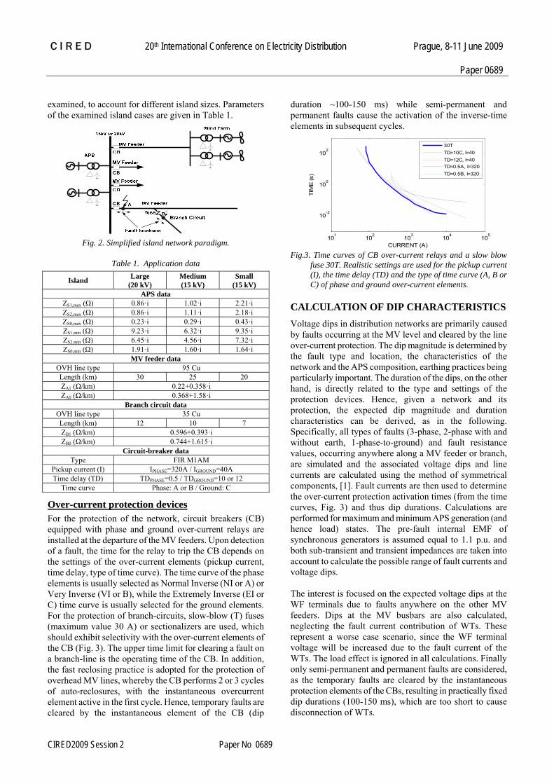
Over-current protection devices For the protection of the network, circuit breakers (CB) equipped with phase and ground over-current relays are installed at the departure of the MV feeders. Upon detection of a fault, the time for the relay to trip the CB depends on the settings of the over-current elements (pickup current, time delay, type of time curve). The time curve of the phase elements is usually selected as Normal Inverse (NI or A) or Very Inverse (VI or B), while the Extremely Inverse (EI or C) time curve is usually selected for the ground elements. For the protection of branch-circuits, slow-blow (T) fuses (maximum value 30 A) or sectionalizers are used, which should exhibit selectivity with the over-current elements of the CB (Fig. 3). The upper time limit for clearing a fault on a branch-line is the operating time of the CB. In addition, the fast reclosing practice is adopted for the protection of overhead MV lines, whereby the CB performs 2 or 3 cycles of auto-reclosures, with the instantaneous overcurrent element active in the first cycle. Hence, temporary faults are cleared by the instantaneous element of the CB (dip
duration ~100-150 ms) while semi-permanent and permanent faults cause the activation of the inverse-time elements in subsequent cycles.
101 102 103 104 105
10-2
100
102
CURRENT (A)
TIM
E (s
)
30TTD=10C, I=40TD=12C, I=40TD=0.5A, I=320TD=0.5B, I=320
Fig.3. Time curves of CB over-current relays and a slow blow
fuse 30T. Realistic settings are used for the pickup current (I), the time delay (TD) and the type of time curve (A, B or C) of phase and ground over-current elements.
CALCULATION OF DIP CHARACTERISTICS Voltage dips in distribution networks are primarily caused by faults occurring at the MV level and cleared by the line over-current protection. The dip magnitude is determined by the fault type and location, the characteristics of the network and the APS composition, earthing practices being particularly important. The duration of the dips, on the other hand, is directly related to the type and settings of the protection devices. Hence, given a network and its protection, the expected dip magnitude and duration characteristics can be derived, as in the following. Specifically, all types of faults (3-phase, 2-phase with and without earth, 1-phase-to-ground) and fault resistance values, occurring anywhere along a MV feeder or branch, are simulated and the associated voltage dips and line currents are calculated using the method of symmetrical components, [1]. Fault currents are then used to determine the over-current protection activation times (from the time curves, Fig. 3) and thus dip durations. Calculations are performed for maximum and minimum APS generation (and hence load) states. The pre-fault internal EMF of synchronous generators is assumed equal to 1.1 p.u. and both sub-transient and transient impedances are taken into account to calculate the possible range of fault currents and voltage dips. The interest is focused on the expected voltage dips at the WF terminals due to faults anywhere on the other MV feeders. Dips at the MV busbars are also calculated, neglecting the fault current contribution of WTs. These represent a worse case scenario, since the WF terminal voltage will be increased due to the fault current of the WTs. The load effect is ignored in all calculations. Finally only semi-permanent and permanent faults are considered, as the temporary faults are cleared by the instantaneous protection elements of the CBs, resulting in practically fixed dip durations (100-150 ms), which are too short to cause disconnection of WTs.

C I R E D 20th International Conference on Electricity Distribution Prague, 8-11 June 2009
Paper 0689
CIRED2009 Session 2 Paper No 0689
RESULTS AND DISCUSSION In Fig. 4, the magnitude-duration characteristics for the expected voltage dips due to 3-phase faults, occurring anywhere in the distribution network of the three islands, are compared with the FRT curves of the selected grid codes (Fig. 1). Notably, although 3-phase faults are the most severe, they represent a small percentage (less than 10%) of the faults occurring in distribution networks. Points lying below the FRT curves are observed only for minimum APS generation, i.e. when the electrical system is weakest, and mainly for the Danish code limits (>100kV). If the NI (A) time curve is selected for the phase elements of the CBs, the violations are reduced, while selecting the VI (B) time curve results in increased violations, not only of the Danish code limits but also for the British and Spanish codes. The German code limits appear to ensure the best immunity characteristics.
10-2 10-1 100 101 102 1030
20
40
60
80
100
120
TIME (s)
Line
-to-L
ine
Vol
tage
(%)
Maximum APS generation (TD=0.5A,I=320)Minimum APS generation (TD=0.5A,I=320)Maximum APS generation (TD=0.5B,I=320)Minimum APS generation (TD=0.5B,I=320)BRITISH CODEGERMAN CODESPANISH CODE (3-phase faults)DANISH CODE (<100kV)DANISH CODE (>100kV)
(a)
10-2 10-1 100 101 102 1030
20
40
60
80
100
120
TIME (s)
Line
-to-L
ine
Vol
tage
(%)
Maximum APS generation (TD=0.5A,I=320)Minimum APS generation (TD=0.5A,I=320)Maximum APS generation (TD=0.5B,I=320)Minimum APS generation (TD=0.5B,I=320)BRITISH CODEGERMAN CODESPANISH CODE (3-phase faults)DANISH CODE (<100kV)DANISH CODE (>100kV)
(b)
10-2 10-1 100 101 102 1030
20
40
60
80
100
120
TIME (s)
Line
-to-L
ine
Vol
tage
(%)
Maximum APS generation (TD=0.5A,I=320)Minimum APS generation (TD=0.5A,I=320)Maximum APS generation (TD=0.5B,I=320)Minimum APS generation (TD=0.5B,I=320)BRITISH CODEGERMAN CODESPANISH CODE (3-phase faults)DANISH CODE (<100kV)DANISH CODE (>100kV)
(c)
Fig. 4. Voltage dips due to 3-phase faults in the MV network of three islands and WT FRT curves of selected grid codes. (a)Large island, (b)Medium island, (c)Small island.
Comparing the three diagrams of Fig. 4, the voltage dips in the small island are larger and their duration longer, since the system is weaker and the fault currents lower, whereas the smallest dips are encountered in the large island for maximum APS generation. However, this is not the situation for minimum APS generation, as the equivalent APS impedances are comparable for the large and small islands (Table 1). Nevertheless, the duration of dips is shorter in the large island, as the higher nominal system voltage (20 kV) results in increased fault currents for the same impedances. Fig. 5 illustrates the characteristics of dips occurring in all three line voltages, due to unsymmetrical faults. All results are for the medium size island case. The grid codes examined in the paper provide very limited information regarding unbalanced faults (e.g. 2-phase faults in the Spanish code). This is partly justified, as they refer to installations connected to the transmission grid, where distance relays with definite time stages are the main protection. Thus the duration of dips is the same for all types of faults, whereas their magnitudes are different. The 3-phase faults are generally the most severe for the stability of WTs and thus ensuring WT FRT capability for this type may suffice. However, in the case of distribution networks protected by time over-current relays, the duration of dips differs for the various fault types, depending on the magnitude of the resulting fault currents. For this reason, the voltage dip characteristics due to unbalanced faults are also correlated with the WT FRT curves in Fig. 5. Ιn Fig. 5(a) the magnitude-duration characteristics for voltage dips due to 2-phase faults without earth are correlated with the WT FRT curves. Referring to the minimum of the three line-to-line voltages, similar remarks hold as for the 3-phase faults, with a higher number of points lying below the FRT curves now. However, it is emphasized that a 2-phase fault which generates a severe dip in one of the line voltages, possibly lying below the FRT curve, will not necessarily lead to the disconnection of a WT fulfilling the respective FRT requirements for 3-phase faults. The respective diagram for 2-phase-to-ground faults is presented in Fig. 5(b). Comparing to Fig. 5(a), the violations of the FRT curves are now reduced. Τhe duration of the associated voltage dips is quite shorter, as in this case the faults are cleared by the faster activation of either the phase or the ground over-current elements. In Fig. 5(c) the magnitude-duration characteristics are presented for voltage dips due to 1-phase-to-ground faults, which constitute the vast majority of faults in MV networks. For directly grounded APS transformers, the zero sequence impedance is smaller than the positive sequence one (Table 1) and hence the phase voltages in the unfaulted phases do not rise, while the line-to-line voltages deviate significantly

C I R E D 20th International Conference on Electricity Distribution Prague, 8-11 June 2009
Paper 0689
CIRED2009 Session 2 Paper No 0689
from the nominal value. If the electrical system was resistance-grounded, then all line voltages would remain close to the nominal and the operation of WTs, connected via Dyn transformers, would not be affected. Nevertheless, line voltage dips in Fig. 5(c) always lie above all FRT curves.
10-2 10-1 100 101 102 1030
20
40
60
80
100
120
TIME (s)
Line
-to-L
ine
Vol
tage
(%)
Max APS generation (TD=0.5A,I=320)Min APS generation (TD=0.5A,I=320)Max APS generation (TD=0.5B,I=320)Min APS generation (TD=0.5B,I=320)GERMAN CODE BRITISH CODEDANISH CODE (>100kV)DANISH CODE (<100kV)SPANISH CODE (2-phase faults)
(a)
10-2 10-1 100 101 102 1030
20
40
60
80
100
120
TIME (s)
Line
-to-L
ine
Vol
tage
(%)
Max APS generation (TD=0.5A,I=320-TD=10C,I=40)Min APS generation (TD=0.5A,I=320-TD=10C,I=40)Μax APS generation (TD=0.5A,I=320-TD=12C,I=40)Min APS generation (TD=0.5A,I=320-TD=12C,I=40)BRITISH CODEDANISH CODE (<100kV)DANISH CODE (>100kV)GERMAN CODESPANISH CODE (2-phase faults)
(b)
10-2 10-1 100 101 102 1030
20
40
60
80
100
120
TIME (s)
Line
-to-L
ine
Vol
tage
(%)
Μax APS generation (TD=10C,I=40)Min APS generation (TD=10C,I=40)Max APS generation (TD=12C,I=40)Min APS generation (TD=12C,I=40)GERMAN CODEBRITISH CODEDANISH CODE (<100kV)DANISH CODE (>100kV)SPANISH CODE (2-phase faults)SPANISH CODE (3-phase faults)
(c)
Fig. 5. Voltage dips due to unsymmetrical faults in the MV network of a medium-size island and WT FRT curves of selected grid codes. (a) 2-phase faults without earth, (b) 2-phase-to-ground faults, (c) 1-phase-to-ground faults.
At this point it should be noted that the examined FRT curves refer to WFs connected to the transmission system, where reclosing cycles are reduced or not applied and hence a single or double voltage dip is experienced by the WF per system fault, respectively. In the case of distribution networks with CB reclosing operations, as in this study, a permanent fault on a feeder causes up to four consecutive dips (if one fast and two time-delayed reclosing cycles are employed), with a very short time distance from each other, which constitute a more severe disturbance for WTs. Nevertheless, despite the differences between transmission and distribution networks, calculating voltage dip
characteristics in island distribution networks and correlating them with common WT FRT curves, provides adequate information to draw conclusions on the suitability of commercially available machines for isolated island grids.
CONCLUSIONS In this paper, the magnitude-duration characteristics were calculated for the voltage dips expected in the MV networks of isolated island grids. For this purpose, typical simplified island systems were assumed, including their specific protection settings, and characteristics have been derived for the expected dips at the MV busbars, for all types of faults and fault resistances in the MV network. These characteristics were subsequently compared to the FRT requirements of several grid codes (Germany, Denmark, Great Britain and Spain). The results indicate that commercially available WTs fulfilling the grid code FRT requirements are also suitable for islands or other weak grids of similar type. Further, a proper selection of over-current protection settings may also have a positive effect on the expected WT immunity to dips. Best choices for the time curves proved to be the NI (A) for the phase over-current relays and the EI (C) for the ground relays, using as time delays the minimum settings that assure cooperation with the slow-blow fuses. REFERENCES [1] Math H.J. Bollen, 1999, Understanding Power Quality
Problems – Voltage sags and interruptions, Wiley-IEEE Press.
[2] Math H.J. Bollen, P. Goossens, A. Robert, 2004, "Assessment of Voltage Dips in HV-Networks: Deduction of Complex Voltages from the Measured RMS Volages", IEEE Transactions on Power Delivery, vol. 19, 783-790.
[3] H. Renner, M Sakulin, 2004, "Calculation of Voltage Dips in Meshed Grids", Proceedings of 11th International Conference on Harmonics and Quality of Power, 666-671
[4] J. Järvinen, J. Pylvänäinen, P. Verho, 2004, "Voltage Dips Analysis as Part of Network Planning Software", Proceedings of Nordic Distribution and Asset Management Conference, Nordac
[5] Math H.J. Bollen, G. Olguin, M. Martins, 2004, "Voltage Dips at the Terminals of Wind Power Installations", Proceedings of Nordic Wind Power Conference
[6] S. Uski, S. Hänninen, B. Lemström, 2006, "Electric network faults seen by a wind farm – analysis of measurement data", Proceedings of EWEC
[7] M. Tsili, Ch. Patsiouras, S. Papathanassiou, 2008, "Grid code requirements for large wind farms: A review of technical regulations and available wind turbine technologies", Proceedings of EWEC