Evaluation of ultra-compact rectifiers for low power, high ... · Power density in electrical...
8
Evaluation of ultra-compact rectifiers for low power, high-speed, permanent-magnet generators D. Krähenbühl 1 , C Zwyssig 2 , K. Bitterli 1 , M. Imhof 1 and J. W. Kolar 1 1 Power Electronic Systems Laboratory, ETH Zurich, Switzerland 2 Celeroton Ltd., Zurich, Switzerland [email protected] Abstract – Literature reports several future portable and distributed power supplies in the watt to kilowatt range based on rotating machinery equipped with a variable-speed permanent- magnet generator. In order to generate a constant dc voltage, an ultra-compact, highly efficient, low power rectifier is required. In this paper, different topologies are compared concerning losses, volume and control complexity. The most suitable, the half controlled three-phase PWM boost rectifier (HCBR) is selected and evaluated, and a novel modulation scheme enhancing the power electronics efficiency is proposed. The integration into a compressed-air-to-electric-power-system with a generator rotating at 350 000 rpm is presented including measurement results. I. INTRODUCTION Ultra-high-speed micro gas and air turbines with an electric output power of a couple of watts to a few 100 W have been widely reported in literature [1] - [8]. The main applications for such systems are power supplies in consumer electronics, automobiles, aircraft and robots or portable/back-up generators. Power density in electrical machines increases with increasing rotational speed [9]. Therefore, for highest power density, these systems are operating at speeds between 100 000 rpm and 1 Mrpm at power levels of up to several kilowatts. A typical characteristic of all the systems is the variable speed depending on the load. In combination with a three-phase generator this leads to a variable three-phase output voltage, which has to be controlled to a constant dc voltage usually required for applications in this power range. However, in literature only systems with variable dc output voltage [1] and variable three-phase ac voltages [3] have been presented. Since such a device should be able to follow unpredictable load changes, the output power can vary from 0 W to full load, while the output voltage must remain constant. Besides ultra-high-speed micro turbine generator systems also other applications are in need of a rectifier. In [10] a wearable power system is presented which can be carried easily on the body and supplies an average of 20 W for 4 days (with a peak power of 200 W) and has a total system weight of less than 4 kg. Such a system is developed for power supply of infantry soldier’s equipment but could also be used in civil applications. In addition, mesoscale energy harvesting technologies like small-scale wind turbines and micro-hydro power systems for charging batteries on boats, caravans or mountain shelters, to supply consumer electronics or to provide electricity for lights need reliable power electronics to provide a constant output voltage [11]-[12]. All of these systems require a rectifier for supplying a constant dc voltage. Fig. 1. Block diagram of the compressed-air-to-electric-power system including a valve for output power regulation and the rectifier for converting a variable three-phase input voltage into a constant dc output voltage. Fig. 2. Rotor with attached turbine and generator stator of the ultra compact (22 mm x 60 mm) air-to-power demonstrator. TABLE I: GENERATOR DATA parameter description value unit n max maximum speed 500 000 rpm n r rated speed 350 000 rpm Ψ PM magnet flux linkage 0.32 mVs L S stator inductance 2.1 μH R S stator resistance 0.12 Ω This paper starts with a short description of a compressed-air- to-electric-power turbine generator system, leading to the specifications for the rectifier. Then, different three-phase rectifiers for such a turbine generator system are evaluated, compared concerning losses, total efficiency, common mode (CM) volume and control complexity and the most suitable topology is selected and experimentally verified and tested with different modulation methods. II. COMPRESSED-AIR-TO-ELECTRIC-POWER-SYSTEM In [8], a miniature compressed-air-to-electric-power system, based on a single-stage axial impulse turbine with a rated
-
Upload
nguyentram -
Category
Documents
-
view
220 -
download
1
Transcript of Evaluation of ultra-compact rectifiers for low power, high ... · Power density in electrical...
Evaluation of ultra-compact rectifiers for low power, high-speed, permanent-magnet generators
D. Krähenbühl1, C Zwyssig2, K. Bitterli1, M. Imhof1 and J. W. Kolar1
1Power Electronic Systems Laboratory, ETH Zurich, Switzerland
2Celeroton Ltd., Zurich, Switzerland
Abstract – Literature reports several future portable and distributed power supplies in the watt to kilowatt range based on rotating machinery equipped with a variable-speed permanent-magnet generator. In order to generate a constant dc voltage, an ultra-compact, highly efficient, low power rectifier is required. In this paper, different topologies are compared concerning losses, volume and control complexity. The most suitable, the half controlled three-phase PWM boost rectifier (HCBR) is selected and evaluated, and a novel modulation scheme enhancing the power electronics efficiency is proposed. The integration into a compressed-air-to-electric-power-system with a generator rotating at 350 000 rpm is presented including measurement results.
I. INTRODUCTION
Ultra-high-speed micro gas and air turbines with an electric output power of a couple of watts to a few 100 W have been widely reported in literature [1] - [8]. The main applications for such systems are power supplies in consumer electronics, automobiles, aircraft and robots or portable/back-up generators. Power density in electrical machines increases with increasing rotational speed [9]. Therefore, for highest power density, these systems are operating at speeds between 100 000 rpm and 1 Mrpm at power levels of up to several kilowatts. A typical characteristic of all the systems is the variable speed depending on the load. In combination with a three-phase generator this leads to a variable three-phase output voltage, which has to be controlled to a constant dc voltage usually required for applications in this power range. However, in literature only systems with variable dc output voltage [1] and variable three-phase ac voltages [3] have been presented. Since such a device should be able to follow unpredictable load changes, the output power can vary from 0 W to full load, while the output voltage must remain constant.
Besides ultra-high-speed micro turbine generator systems also other applications are in need of a rectifier. In [10] a wearable power system is presented which can be carried easily on the body and supplies an average of 20 W for 4 days (with a peak power of 200 W) and has a total system weight of less than 4 kg. Such a system is developed for power supply of infantry soldier’s equipment but could also be used in civil applications. In addition, mesoscale energy harvesting technologies like small-scale wind turbines and micro-hydro power systems for charging batteries on boats, caravans or mountain shelters, to supply consumer electronics or to provide electricity for lights need reliable power electronics to provide a constant output voltage [11]-[12]. All of these systems require a rectifier for supplying a constant dc voltage.
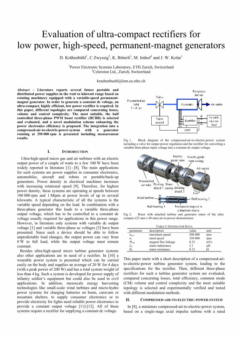
Fig. 1. Block diagram of the compressed-air-to-electric-power system including a valve for output power regulation and the rectifier for converting a variable three-phase input voltage into a constant dc output voltage.
Fig. 2. Rotor with attached turbine and generator stator of the ultra compact (22 mm x 60 mm) air-to-power demonstrator.
TABLE I: GENERATOR DATA parameter description value unit nmax maximum speed 500 000 rpm nr rated speed 350 000 rpm ΨPM magnet flux linkage 0.32 mVs LS stator inductance 2.1 μH RS stator resistance 0.12 Ω
This paper starts with a short description of a compressed-air-to-electric-power turbine generator system, leading to the specifications for the rectifier. Then, different three-phase rectifiers for such a turbine generator system are evaluated, compared concerning losses, total efficiency, common mode (CM) volume and control complexity and the most suitable topology is selected and experimentally verified and tested with different modulation methods.
II. COMPRESSED-AIR-TO-ELECTRIC-POWER-SYSTEM
In [8], a miniature compressed-air-to-electric-power system, based on a single-stage axial impulse turbine with a rated

rotational speed of 350 000 rpm and a rated electric power output of 60 W is presented (Fig. 1 and Fig. 2). With a passive ac load, a maximum electric output power of 124 W and a maximum system efficiency of 24% have been experimentally determined. The system efficiency has been measured from pressurized air flow to electric power, including turbine and generator efficiency. Fig. 3 shows the electric output power as a function of speed and supply pressure. The maximal electric power output is around 124 W at 370 000 rpm and the maximal measured torque is 5 mNm at 240 000 rpm. The operating point has been changed by varying the passive resistive three-phase load and the supply pressure. The turbine generator system has been tested up to 500 000 rpm and 6 bar supply pressure. In Table I measured generator data are compiled. Exchanging the variable three-phase load by a rectifier controlling the output to a fixed dc voltage takes significant influence on stable working points. Only working points on the right hand side of the line indicating highest efficiencies in Fig. 3 are stable.
III. RECTIFIER SPECIFICATIONS
The power electronics must be able to convert a variable three-phase input voltage with high frequency into a constant output dc voltage (Fig. 1). The high fundamental phase current frequency (up to 8333 Hz), the aim to build the system as compact as possible and a high converter efficiency (in order not to compromise the overall system efficiency) are the main challenges. In [14]-[17] several possible 1-phase and 3-phase boost ac-dc-converters are summarized.
In a PM generator, the magnitude of the back EMF is proportional to the speed. In order to supply a constant dc output voltage, in this case 24 Vdc, also at low speeds, boost functionality is required. The maximal power output is limited to 150 W, which leads to a dc current of 6.25 A.
In order to make the overall system volume as small as possible the rectifier should be integrated into the turbine generator system. This avoids an additional heat sink for the power and control electronics because the rectifier can be attached to the generator casing and thereby cooled by the air flow.
IV. TOPOLOGIES AND SIMULATIONS
A. Active three-phase PWM rectifier An active three-phase PWM rectifier with sinusoidal phase currents is the state of the art solution in drive systems (Fig. 4). However, it is not naturally the best choice, because it leads to excessive switching frequencies (>500 kHz) or a large sinusoidal filter. An encoder and two parallel current measurements in the generator phases are additionally required to control the currents and an extremely high current control-loop bandwidth is required which pushes the limits of current measurement, analog signal electronics, controller and gate driver design, and switching time. Finally, sinusoidal currents with a low ripple are not essentially required due to the special slotless generator topology which allows a high ripple current without increased generator losses [13], and also the torque ripple is not relevant due to the inertia of the turbine.
0 200 400 6000
20
40
60
80
100
120
140
speed (krpm)
elec
tric
powe
r (W
)
2 bar
3 bar
4 bar5 bar
6 bar
Fig. 3. Electric power generated by the turbine generator system as a function of speed and supply pressure. The line indicates the region of highest system efficiency.
Fig. 4. Active three-phase PWM rectifier with additional ac filter inductors (grey) and encoder.
UDC
Generator
ADCADC
DSPUref
Sectordetection
PWM
UmeasImeas
+
-
UDC1
LDC
Speed and position
calculation
PI current controller
D1 D3 D5
D2 D4 D6
PI voltage controller
SB1
SB2
Fig. 5. Full bridge rectifier with additional boost converter. The three-phase diode rectifier can be exchanged with MOSFETs , in order to reduce conduction losses (grey).
UDCGenerator
ADCADC
DSPUref
Sectordetection
UmeasImeas
+
-
L3
L3
L2
PWM
Filter
PI current controller
Speed and position
calculation
D1 D3 D5
S2 S4 S6
PI voltage controller
Fig. 6. Half controlled three-phase PWM boost rectifier (HCBR). For the modulation scheme with synchronous switching the sector detection must not to be implemented (grey), see section IV.C. The high side diodes can be exchanged with MOSFETs in order to reduce conduction losses or if bidirectional operation is required (grey).

Fig. 7. Simulation results of the three-phase full bridge rectifier with boost converter. Generator back EMF uemf,a (blue) and terminal voltage ut,a (black), phase current ia, output voltage uDC (black) and uDC1 (blue) and switching signals for one half bridge of the rectifier TS1,S2 as well as CM voltage uCM and current iCM are shown. The switching frequency of the boost converter is fs = 200 kHz and the fundamental frequency is ff = 5833 Hz while CY-GND was assumed to be 48 pF.
However, the active three-phase PWM rectifier also has
advantages. If a bidirectional behavior is necessary, e.g. start of a gas turbine, the active three-phase PWM rectifier is an appropriate solution.
B. Active or passive three-phase rectifier with boost converter
The second option is a passive or active unidirectional three-phase diode rectifier with additional boost converter (Fig. 5), in order to ensure a constant output voltage. The diodes are conducting for 120° and are commutating with fundamental frequency. Considering the loss calculations in Table II, the rather high rectifier diode losses can be reduced by exchanging them with MOSFETs, i.e. by synchronous rectification, but then an encoder or a 60° sector detection unit (Fig. 13) is required.
The main disadvantages of the full bridge rectifier with additional boost converter are the large number of semiconductors, the rather large dc inductor and the higher conduction losses due to 3 semiconductors in the current path. If a dc-link capacitor is used, the phase currents have the well known 60° pulse characteristic, while if the dc-link capacitor
is omitted one can achieve a 120° block waveform. When bidirectional operation is required, the diodes must be exchanged with switches (indicated in Fig. 5). The simulation results (no dc-link capacitor and with active bridge) are presented in Fig. 7.
C. Half controlled three-phase PWM boost rectifier (HCBR)
The half controlled three-phase PWM boost rectifier (HCBR or bridgeless boost topology) has been introduced in [14]-[16], and for one-phase in [17] [18] respectively. It is a simple and economical circuit for applications where a maximal power factor of λ = 3/π = 0.955 and a total harmonic distortion of THD = 30% (when neglecting the current ripple and assuming rectangular current waveform) is sufficient. An advantage of the HCBR compared to the passive diode rectifier with boost converter is that the inductor current flows through only two semiconductors, which reduces conduction losses and therefore increases efficiency. Advantages of the HCBR compared to an active three-phase rectifier are the simple structure, the shoot through free bridge leg structure, and that only one current sensor and current control loop is required. Also, only three controlled switches and gate drivers with a single power supply (common source) are needed. Compared with a diode rectifier a better performance, an actively controlled output voltage and a lower input current THD can be achieved. Considering the overall volume, the HCBR can be built much smaller because no additional dc inductor is required and the number of semiconductors can be significantly reduced. Instead of using three additional ac filter inductors the stator inductors of the generator can be used. If they are too small or no high switching frequency is tolerated, only small additional ac filter inductors are required (indicated in Fig. 6).
When replacing the high side diodes with switches, and therefore increasing control complexity, bidirectional operation and further reduction of the diode conduction losses can be achieved. Then, with a brushless-dc modulation method [19], a gas turbine can be started. In order to avoid a high switching frequency and large ac inductors the maximum ripple current is chosen to be a large value of 2 A (compared to the maximum current of 6 A), and this results in a switching frequency of approximately 200 kHz to 400 kHz.
1. HCBR space vector representation The functionality of the HCBR can be analyzed with the
space vector representation. Assuming continuous conduction in the three phases and currents ia,b,c in phase with the back emf voltages uemf,a,b,c, two different phase current patterns must be considered (Fig. 8 and Fig. 9).
For assuming two positive and one negative phase current, i.e. ia > 0, ib > 0, ic < 0 (interval II in Fig. 9): The current in phase a and b can flow through the diode D1/D3 to the high side (MOSFET S2/S4 off) or to ground (MOSFET S2/S4 on), while the current in phase c must flow through the MOSFET S6 or its body diode. In this case, four of eight possible space vectors are available, namely uu,(100), uu,(010), uu,(110) and, uu,(000), which implies that sinusoidal currents can be formed in interval II. With the same approach it can be seen that also
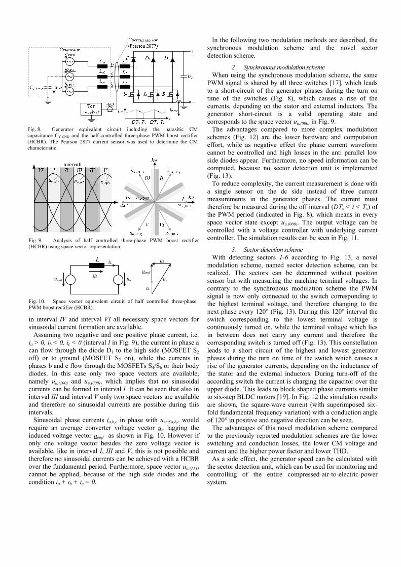
Fig. 8. Generator equivalent circuit including the parasitic CM capacitance CY-GND and the half-controlled three-phase PWM boost rectifier (HCBR). The Pearson 2877 current sensor was used to determine the CM characteristic.
Fig. 9. Analysis of half controlled three-phase PWM boost rectifier (HCBR) using space vector representation.
uemf
uu
uL
iL
uemf uu
L iL
uL
Fig. 10. Space vector equivalent circuit of half controlled three-phase PWM boost rectifier (HCBR).
in interval IV and interval VI all necessary space vectors for sinusoidal current formation are available.
Assuming two negative and one positive phase current, i.e. ia > 0, ib < 0, ic < 0 (interval I in Fig. 9), the current in phase a can flow through the diode D1 to the high side (MOSFET S2 off) or to ground (MOSFET S2 on), while the currents in phases b and c flow through the MOSFETs S4/S6 or their body diodes. In this case only two space vectors are available, namely uu,(100) and uu,(000), which implies that no sinusoidal currents can be formed in interval I. It can be seen that also in interval III and interval V only two space vectors are available and therefore no sinusoidal currents are possible during this intervals.
Sinusoidal phase currents ia,b,c in phase with uemf,a,b,c would require an average converter voltage vector uu lagging the induced voltage vector uemf as shown in Fig. 10. However if only one voltage vector besides the zero voltage vector is available, like in interval I, III and V, this is not possible and therefore no sinusoidal currents can be achieved with a HCBR over the fundamental period. Furthermore, space vector uu,(111) cannot be applied, because of the high side diodes and the condition ia + ib + ic = 0.
In the following two modulation methods are described, the synchronous modulation scheme and the novel sector detection scheme.
2. Synchronous modulation scheme When using the synchronous modulation scheme, the same
PWM signal is shared by all three switches [17], which leads to a short-circuit of the generator phases during the turn on time of the switches (Fig. 8), which causes a rise of the currents, depending on the stator and external inductors. The generator short-circuit is a valid operating state and corresponds to the space vector uu,(000) in Fig. 9.
The advantages compared to more complex modulation schemes (Fig. 12) are the lower hardware and computation effort, while as negative effect the phase current waveform cannot be controlled and high losses in the anti parallel low side diodes appear. Furthermore, no speed information can be computed, because no sector detection unit is implemented (Fig. 13).
To reduce complexity, the current measurement is done with a single sensor on the dc side instead of three current measurements in the generator phases. The current must therefore be measured during the off interval (DTs < t < Ts) of the PWM period (indicated in Fig. 8), which means in every space vector state except uu,(000). The output voltage can be controlled with a voltage controller with underlying current controller. The simulation results can be seen in Fig. 11.
3. Sector detection scheme With detecting sectors 1-6 according to Fig. 13, a novel
modulation scheme, named sector detection scheme, can be realized. The sectors can be determined without position sensor but with measuring the machine terminal voltages. In contrary to the synchronous modulation scheme the PWM signal is now only connected to the switch corresponding to the highest terminal voltage, and therefore changing to the next phase every 120° (Fig. 13). During this 120° interval the switch corresponding to the lowest terminal voltage is continuously turned on, while the terminal voltage which lies in between does not carry any current and therefore the corresponding switch is turned off (Fig. 13). This constellation leads to a short circuit of the highest and lowest generator phases during the turn on time of the switch which causes a rise of the generator currents, depending on the inductance of the stator and the external inductors. During turn-off of the according switch the current is charging the capacitor over the upper diode. This leads to block shaped phase currents similar to six-step BLDC motors [19]. In Fig. 12 the simulation results are shown, the square-wave current (with superimposed six-fold fundamental frequency variation) with a conduction angle of 120° in positive and negative direction can be seen.
The advantages of this novel modulation scheme compared to the previously reported modulation schemes are the lower switching and conduction losses, the lower CM voltage and current and the higher power factor and lower THD.
As a side effect, the generator speed can be calculated with the sector detection unit, which can be used for monitoring and controlling of the entire compressed-air-to-electric-power system.

Fig. 11. Simulation results of the HCBR with synchronous modulation scheme. Generator back EMF uemf,a (blue) and terminal voltage ut,a (black), phase current ia, output voltage uDC, switching signals for the three-phase legs TS2,S4,S6 as well as CM voltage uCM (including the envelope) and current iCM are shown. The switching frequency is fs = 200 kHz and the fundamental frequency is ff = 5833 Hz while CY-GND was assumed to be 48 pF.
V. HCBR COMMON-MODE (CM) CHARACTERISTICS
The HCBR is also analyzed concerning CM characteristics. The generator terminals are connected to the rectifier, and can be modeled as pulsating voltage sources. These HF pulsating voltage sources charge and discharge the parasitic capacitance CY-GND between output ground (generator casing) and generator star point (Fig. 8), which leads to a small current flow that may disturb other sensitive electronic parts close-by [17] - [18].
The relevant capacitance CY-GND (Fig. 8) has been measured with an impedance analyzer. The capacitance of the three short-circuited power cables of the assembled generator and the generator casing has a value of 48 pF. With this value, the CM currents have been determined with GeckoCIRCUITS simulations [20]. In Fig. 14 the simulated quasi-peak CM conducted emission when using the 60° sector detection unit, a CY-GND of 48 pF and a switching frequency of fs = 200 kHz is shown. Due to the high switching frequency directly at the terminals of the generator, the HCBR causes large CM noise (Fig. 12 and Fig. 11). The full bridge rectifier with additional boost converter causes less CM noise problems, because the high frequency switching voltage is not directly applied to the
Fig. 12. Simulation results of the HCBR with sensor less 60° sector detection modulation scheme. Generator back EMF uemf,a (blue) and terminal voltage ut,a (black), phase current ia, output voltage uDC, switching signals for one phase leg TS2 as well as CM voltage uCM (including the envelope) and current iCM are shown. The switching frequency is fs = 200 kHz and the fundamental frequency is ff = 5833 Hz while CY-GND was assumed to be 48 pF.
Fig. 13. 60° sector definitions for HCBR and three-phase full bridge rectifier with boost converter and the MOSFET signals for the HCBR with sector detection modulation scheme. terminals of the generator and therefore only small CM currents can be observed (Fig. 7).
The envelope of the HF CM voltage when using 60° sector detection unit is
,12CM emf iu u= for switch = on ( 1 )

( ),12CM emf i DCu u u= + for switch = off ( 2 )
illustrated with the blue and red curve in Fig. 12. For synchronous switching the envelope is
0CMu = for switch = on ( 3 )
( ),12CM emf i DCu u u= + for switch = off ( 4 )
illustrated with the blue and red curve in Fig. 11. uemf,i is the back emf of the phase which is not conducting, changing from one phase to the next every 60°. The CM voltage of the full bridge rectifier with additional boost converter follows the highest terminal voltage.
In order to verify the proposed CM propagation model and to test the performance of the simulation shown in Fig. 14, CM measurements of the three-phases have been carried out, employing a HF current probe Pearson 2877 with a nominal bandwidth of 200MHz. Regarding the CM measurements, the current sensor produces an output signal of 1 V/A at an external 50Ω-termination (which lies in parallel to the internal 50Ω-termination of the sensor), which corresponds to an attenuation GPearson of
( )20 log 0.5 6 dB.PearsonG = ⋅ = − ( 5 )
The standard CISPR 11 was chosen for establishing the
performance requirements, where the frequency range of 0.15 MHz to 30 MHz is considered for class A equipment. The limits for this performance test are represented through the red curve in Fig. 14 and Fig. 15. In Fig. 15 a quasi-peak CM conducted emission measurement when using 60° sector detection unit and a switching frequency of fs = 200 kHz, measured with a spectrum analyzer with an input impedance of 50 Ω, is presented. The simulation (Fig. 14) and the measurement (Fig. 15) show good agreement, by trend the simulated conducted emissions (CE) are too high, especially the switching frequency and the harmonics. The first peak at 200 kHz represents the rectifier switching frequency. Only one measurement is shown, but also simulations and measurements with synchronous switching and with switching frequency of fs = 400 kHz show good agreements.
VI. COMPARISON AND SELECTION
The different rectifier topologies are compared concerning efficiency, volume, control complexity and CM characteristics. The results are compiled in Table II. For a fair comparison, a total inductor volume of 800 mm3 is defined, for the topologies requiring additional inductors (dc or ac). The no-load losses represent the DSP and gate driver losses. The passive three-phase rectifier has clearly the lowest efficiency due to the high diode losses, while the active rectifier reaches as high efficiencies as the HCBR. Replacing the high side diodes with switches does not significantly lower the overall losses.
1. Loss measurements and efficiency simulation Special attention is on the switching losses in the
semiconductors, as they have a main influence on the total losses. The total switching losses of the semiconductors (MOSFET: IRF6644 DirectFET and the Diode: IR 12CWQ03FNPbF) have been measured with a test bench setup. Then, the resulting loss coefficients are used in GeckoCIRCUITS [20] to simulate the total losses of the circuit (e.g. switching and conduction losses of the MOSFETs, diode losses, inductor losses and current measurement shunt losses) at the rated operation point of the system for a speed of 350 000 rpm and an electric power output of 25 W to 100 W. The constant DSP losses (1.1 W) and gate driver losses (0.4 W) have been added to the simulation results. In Fig. 19 simulated and measured efficiencies of the HCBR with sensorless 60° sector detection modulation scheme and with synchronous modulation scheme at different output power levels and different switching frequencies are presented. The measured and simulated data show good agreement.
0.15 1 10 30
20
40
60
80
100
120
frequency (MHz)
emiss
ion
leve
l (dBμV
)
Fig. 14. Simulated quasi-peak CM conducted emission when using the sector detection modulation scheme and a switching frequency of fs = 200 kHz.
150 kHz 30 MHz
dBµV dBµV
1 QPVIEW
2 QPCLRWR
1 MHz 10 MHz
10
20
30
40
50
60
70
80
90
100
110
120
130
CLASSA_Q
Fig. 15. Measured quasi-peak CM conducted emission when using the sector detection modulation scheme and a switching frequency of fs = 200 kHz. The sum of the input currents is measured with a current probe Pearson 2877 in order to obtain only the CM signal. The blue signal represents the quasi-peak noise floor.

(a) (b) (a) (b)
(c) (d) (c) (d)
Fig. 16. Measurement results of the HCBR with synchronous modulation scheme at 350 000 rpm, a switching frequency of fs = 200 kHz (a/b) and of fs = 400 kHz (c/d) and a output power of 40 W (a) and 50 W (c) and a output power step (dashed vertical line) from 15 W to 40 W (b) and from 15 W to 50 W (d). Channel 1: terminal voltage, channel 2: phase current, channel 3: output voltage, channel 4: PWM signal for all three switches.
Fig. 17. Measurements results of the HCBR with sector detection modulation scheme at 350 000 rpm, a switching frequency of fs = 200 kHz (a/b) and of fs = 400 kHz (c/d) and a output power of 50 W (a/c) and a output power change (dashed vertical line) from 30 W to 60 W (b) and from 15 W to 75 W (d). Channel 1: terminal voltage, channel 2: phase current, channel 3: output voltage, channel 4: PWM signal for one switch.
0 25 50 75 10086
88
90
92
94
96
98
100
Pout
(W)
effic
ienc
y (%
)
400 kHz sector200 kHz sector400 kHz synchronous200 kHz synchronous
Fig. 18. Half controlled three-phase PWM boost rectifier electronics, including the valve control electronics (90 mm x 30 mm).
Fig. 19. Comparison of simulated (lines) and measured (circles/squares) efficiencies with the HCBR with sector detection modulation scheme (circles) and with synchronous modulation scheme (squares) at different output power levels and different switching frequencies.
TABLE II: COMPARISON OF CONVERTER TOPOLOGIES 1)
passive 1S boost
(6.8 µH, 200 kHz)
active 1S boost
(6.8 µH, 200 kHz)
HCBR active three-phase PWM rectifier 3 ac inductors
(3 x 3.3 µH, 200 kHz) no inductor (400 kHz)
3 ac inductors (3 x 3.3 µH, 200 kHz)
no inductor (400 kHz)
sector synchronous sector synchronous sector sector number of switches 2 8 3 3 3 3 6 6 number of diodes 6 0 3 3 3 3 0 0 volume - - 0 0 + + 0 + sector detection no yes yes no yes no yes yes control complexity + 0 0 + 0 + - - bidirectional no (yes) no no no no yes yes common-mode (CM) + + - - - - - - MOSFET losses 2.8 W 4.0 W 2.4 W 4.5 W 3.5 W 5.8 W 3.9 W 5.4 W diodes losses 6.0 W 0 W 2 W 1.9 W 2.0 W 2.0 W 0 W 0 W inductor losses 1.5 W 1.4 W 4.7 W 4.8 W 0 W 0 W 4.5 W 0 W current measurement shunt 0.6 W 0.6 W 0.4 W 0.4 W 0.4 W 0.4 W 0.4 W 0.4 W no-load losses 1.5 W 1.5 W 1.5 W 1.5 W 1.5 W 1.5 W 1.5 W 1.5 W total losses 12.4 W 7.5 W 11 W 13.1 W 7.4 W 9.7 W 10.3 W 7.3 W efficiency 89.0% 93.0% 90.1% 88.4% 93.1% 91.2% 90.7% 93.2%
1) For n = 350 000 rpm, Pout = 100 W, T = 25°C

2. Topology Selection Based on the comparison in Table II, the HCBR is selected
for further evaluation. The main advantages of this topology are the low number of switches and diodes and the high efficiency, and compared to the active three-phase PWM rectifier the low control complexity. Also for the compressed-air-to-electric power system no bidirectional operation is required. The advantage of synchronous modulation scheme compared to sector detection scheme is the lower hardware and computation effort, while as negative effect no square-wave form in the positive direction can be seen and higher losses in the anti parallel low side diodes appear which lowers the efficiency significantly.
Using higher switching frequency instead of additional ac-inductors gives higher efficiencies at high output power levels and reduces the volume.
VII. MEASUREMENTS
The hardware realization of the ultra compact (22 mm x 60 mm) air-to-power demonstrator [8] and the HCBR electronics (90 mm x 30 mm) are shown in Fig. 2 and Fig. 18 respectively. The hardware was realized in a manner such that both low frequency operation with ac inductors and high frequency operation without ac inductors are possible. In Fig. 17a/c and in Fig. 16a/c measurements with a HCBR at 350 000 rpm and a switching frequency of 200 kHz and 400 kHz are shown. With the sector detection modulation scheme (Fig. 17) the 120° block-type waveform in the positive current flow and the rather high current ripple of approximately 2 A can be seen, while for the modulation scheme with synchronous modulation (Fig. 16) no 120° block waveform in the positive current flow can be achieved. All measurements show good agreement with the simulation results in Fig. 7, Fig. 12 and Fig. 11 respectively. In Fig. 17b/d and Fig. 16b/d a load step on the dc side and the resulting dc voltage and phase current waveform are shown. In Fig. 19 simulated and calculated efficiencies of the HCBR at different output power levels and different switching frequencies are presented.
VIII. CONCLUSION
The two most common rectifiers, the active and the passive three-phase rectifier, the latter with an additional boost converter for constant dc voltage supply, are not the automatic choices for low power, variable-speed, permanent-magnet generators, especially for high rotational speeds of the generator. A rectifier topology comparison considering losses, CM, control complexity and volume results in a selection of the HCBR. Using higher switching frequency instead of additional ac inductors leads to high efficiency at minimum volume. Therefore, the HCBR with no additional ac inductors is found to be the best choice to convert a variable three-phase input voltage with high frequency into a constant output dc voltage. Furthermore, a novel modulation scheme lowering the switching and conduction losses and therefore increasing the efficiency is presented in this paper. Integration into a compressed-air-to-electric-power turbine generator system verifies the theoretical considerations.
REFERENCES [1] D.P. Arnold, P. Galle, F. Herrault, S. Das, J.H. Lang, M.G. Allen. A
Self-Contained, Flow-Powered Microgenerator System. Proceedings of the 5th International Workshop on Micro- and Nanotechnology for Power Generation and Energy Conversion Applications (PowerMEMS 2005), Tokyo, Japan, Nov. 28 - 30.
[2] L.G. Frechette, S.A. Jacobson, K.S. Breuer, F.F. Ehrich, R. Ghodssi, R. Khanna, C.W. Wei Wong, X. Zhang, M.A. Schmidt, A.H. Epstein. Demonstration of a Microfabricated High-Speed Turbine Supported on Gas Bearings. Proc. Solid-State Sensor and Actuator Workshop 2000, Hilton Head Is. NC.
[3] J. Peirs, D. Reynaerts, F. Verplaetsen. A Microturbine for Electric Power Generation. Sensors and Actuators A: Physical Volume 113, Issue 1, pp. 86-93, June 2004.
[4] S. Tanaka, K. Hikichi, S. Togo, M. Murayama, Y. Hirose, T. Sakurai, S. Yuasa, S. Teramoto, T. Niino, T. Mori, M. Esashi, K. Isomura. World’s smallest Gas Turbine establishing Brayton Cycle. Proc. of the 7th International Workshop on Micro and Nanotechnology for Power Generation and Energy Conversion Applications (PowerMEMS 2007), Freiburg, Germany, Nov. 27 - 29, 2007
[5] D. P. Arnold, F. Herrault, I. Zana, P. Galle, J.-W. Park, S. Das, J. H. Lang, and M. G. Allen. Design optimization of an 8-Watt, microscale, axial-flux, Permanent-Magnet Generator. J. Micromech. Microeng., vol. 16, no. 9, pp. S290–S296, Sep. 2006.
[6] B. C. Yen, F. Herrault, K. J. Hillman, M. G. Allen, F. F. Ehrich, S. Jacobson, C. H. Ji, J. H. Lang, H. Li, Z. S. Spakovszky, D. R. Veazie. Characterization of a fully-integrated Permanent-Magnet Turbine Generator. Proceedings of the 8th International Workshop on Micro and Nanotechnology for Power Generation and Energy Conversion Applications (PowerMEMS 2008), Sendai, Japan, Nov. 9 - 12, 2008
[7] H. Raisigel, O. Cugat, and J. Delamare. Permanent Magnet planar micro-Generators. Sensors and Actuators A: Volume 130–131, pp. 438–444, August 2006.
[8] D. Krähenbühl, C Zwyssig, H. Hörler and J. W. Kolar. Design Considerations and Experimental Results of a 60 W Compressed-Air-to-Electric-Power System. 2008 IEEE/ASME International Conference on Mechatronic and Embedded Systems and Applications (MESA), Beijing, China, Oct. 12 – 15.
[9] A. Binder, T. Schneider. High-Speed Inverter-Fed AC Drives. International Aegean Conference on Electrical Machines and Power Electronics, Electromotion 2007, Bodrum, Turkey, Sept. 10-12, 2007.
[10] I. Kovacevic, S.D. Round, J.W. Kolar, K. Boulouchos. Optimization of a Wearable Power System. Proceedings of the 11th Workshop on Control and Modeling for Power Electronics (COMPEL 2008), Aug. 17 - 20, 2008.
[11] G. Boyle, editor. Renewable Energy: Power for a sustainable Future. Oxford: Oxford University Press, 1996.
[12] www.solarwindworks.com [13] N. Bianchi, S. Bolognani, F. Luise. Potentials and Limits of High-
Speed PM Motors. IEEE Trans. Industry Applications, vol. 40, no. 6, pp. 1570-1578, Nov.-Dec. 2004.
[14] J. Kikuchi, M.D. Manjrekar, T.A. Lipo. Performance Improvement of half controlled 3-Phase PWM Boost Rectifier. 30th Annual IEEE Power Electronics Specialists Conference. Volume 1, pp. 319 – 324, 1999.
[15] J.C. Salmon. Circuit Topologies for PWM Boost Rectifiers operated from 1-phase and 3-phase ac Supplies and using either Single or Split dc Rail Voltage Outputs. IEEE Applied Power Electronics (APEC) Conf. Proc., pp. 473-479, Mar. 1995.
[16] J. Miniböck. Dreiphasen Dreischalter Dreipunkt Pulsgleichrichtersys-tem. Ph.D. dissertation, Swiss Federal Institute of Technology Zurich, Switzerland, 2008.
[17] L. Huber, Y. Jang, M. Jovanovic. Performance Evaluation of Bridgeless PFC Boost Rectifier. IEEE Transactions on Power Electronics, Vol. 23, No. 3, pp. 1381 - 1390, 2008.
[18] H. Ye, Z. Yang, J. Dai, C. Yan, X. Xin, J. Ying. Common Mode Noise Modeling and Analysis of Dual Boost PFC Circuit. Proceedings of the 26th IEEE Intern. Telecommunications Energy Conference, Sept. 19 - 23, pp. 575 - 582, 2004.
[19] K. Iizuka, H. Uzuhashi, M. Kano, T. Endo, K. Mohri. Microcomputer Control for Sensorless Brushless Motor. Industry Applications, IEEE Transactions on , vol.IA-21, no.3, pp.595-601, May 1985
[20] www.gecko-research.com