EVALUATION OF THE PERFORMANCE OF …eprints.usq.edu.au/24717/1/Hautsalo_2013.pdfEVALUATION OF THE...
67
University of Southern Queensland FACULTY OF HEALTH, ENGINEERING & SCIENCES EVALUATION OF THE PERFORMANCE OF DIFFERENT GLOBAL SATELLITE NAVIGATION SYSTEMS (GNSS) FOR AUSTRALIAN GNSS USERS A dissertation Submitted by Kari Hautsalo in fulfilment of the requirements of Courses ENG4111 and 4112 Research Project Towards the degree of Bachelor of Spatial Science (Surveying)
Transcript of EVALUATION OF THE PERFORMANCE OF …eprints.usq.edu.au/24717/1/Hautsalo_2013.pdfEVALUATION OF THE...

University of Southern Queensland
FACULTY OF HEALTH, ENGINEERING & SCIENCES
EVALUATION OF THE PERFORMANCE OF DIFFERENT
GLOBAL SATELLITE NAVIGATION SYSTEMS (GNSS)
FOR AUSTRALIAN GNSS USERS
A dissertation Submitted by
Kari Hautsalo
in fulfilment of the requirements of Courses
ENG4111 and 4112 Research Project
Towards the degree of
Bachelor of Spatial Science (Surveying)
i
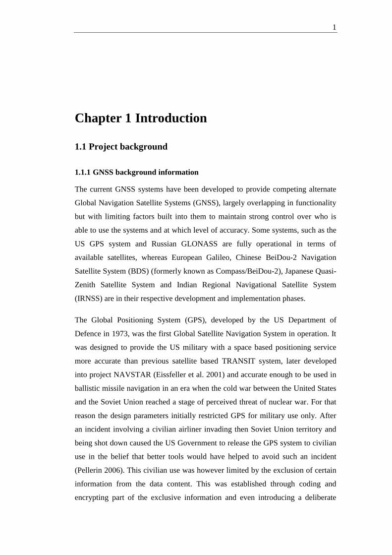
Abstract
Satellite navigation has been available in the aviation and maritime worlds since GPS system
was built in the 1970's and users were able to navigate anywhere in the world with unheard-
of accuracy of less than a hundred meters. Since then other systems have emerged and a new
term, Global Navigation Satellite System was born to generalise the concept.
Now that there are four different GNSS systems in a stage of development that includes
satellites in orbit, it is prudent to ask the question: which GNSS system best suits the
Australian user? This project took the task of finding information about all four GNSS
systems that would enable an evaluation of performance of each system.
The project devised an evaluation framework for ranking the benefits and a methodology of
assessing identified indicators of such suitability against that framework. As a result,
differences were found, impacts of those differences were assessed and results tabulated in a
matrix of ranking.
With limited resources and scope, the results can be seen as discussion enhancing rather than
authoritative points of view and others may have other ideas of where the emphasis should
lie.
The project report nevertheless covers a wide range of topics that would be included in any
assessment into the needs of an Australian user.

i
University of Southern Queensland
FACULTY OF HEALTH, ENGINEERING & SCIENCES
SCHOOL OF ENGINEERING AND SURVEYING
ENG 4111 & ENG4112 Research Project
Limitations of Use
The Council of the University of Southern Queensland, its Faculty of Health, Engineering & Sciences,
and the staff of the University of Southern Queensland, do not accept any responsibility for the truth,
accuracy or completeness of material contained within or associated with this dissertation.
Persons using all or any part of this material do so at their own risk, and not at the risk of the Council
of the University of Southern Queensland, its Faculty of Health, Engineering & Sciences or the staff
of the University of Southern Queensland.
This dissertation reports an educational exercise and has no purpose or validity beyond this exercise.
The sole purpose of the course pair entitled "Research Project" is to contribute to the overall education
within the student's chosen degree program. This document, the associated hardware, software,
drawings, and other material set out in the associated appendices should not be used for any other
purpose: if they are so used, it is entirely at the risk of the user.
Assoc Prof Kevin McDougall
Head of School (Civil Engineering and Surveying)
Faculty of Health, Engineering & Sciences

i
Certification
I certify that the ideas, designs and experimental work, results, analysis and conclusions set
out in this dissertation are entirely my own effort, except where otherwise indicated and
acknowledged.
I further certify that the work is original and has not been previously submitted for
assessment in other course or institution, except where specifically stated.
Kari Kauko Juhani Hautsalo
Student Number: 0050100245
Signature
Date

ii
Acknowledgements
I would like to take this opportunity to thank the following people for their assistance with
this paper.
My University of Southern Queensland project supervisor, Dr Dev Raj Paudyal, for providing
me with the direction of this topic and writing this project report.
Gassman Development Perspectives Pty Ltd, for allowances made towards studies.
My family and colleagues, not only for this project but for all the years of studies.

iii
Contents
Abstract ....................................................................................................................................... i
University of Southern Queensland ............................................................................................ i
Acknowledgements .................................................................................................................... ii
Contents ................................................................................................................................... iii
List of figures ............................................................................................................................. v
List of tables .............................................................................................................................. vi
Glossary ................................................................................................................................... vii
Chapter 1 Introduction ............................................................................................................... 1
1.1 Project background .......................................................................................................... 1
1.1.1 GNSS background information ................................................................................ 1
1.1.2 Project context .......................................................................................................... 3
1.2 Project aims and objectives .............................................................................................. 4
1.2.1 Project aims ............................................................................................................... 4
1.2.2 Project objectives ...................................................................................................... 4
1.3 Scope and assumptions of the project .............................................................................. 4
1.4 Evaluation framework ...................................................................................................... 5
1.5 Structure and outline of the report ................................................................................... 6
1.6 Chapter summary ............................................................................................................. 8
Chapter 2 Literature review ....................................................................................................... 9
2.1 Introduction ...................................................................................................................... 9
2.2 The physical perspective .................................................................................................. 9
2.3 The application perspective ........................................................................................... 13
2.4 The control perspective .................................................................................................. 17
2.5 Australian perspective .................................................................................................... 18
2.6 Conclusions .................................................................................................................... 18

iv
Chapter 3 Methodology ........................................................................................................... 20
3.1 Introduction .................................................................................................................... 20
3.2 Methodology of evaluation ............................................................................................ 20
3.3 General framework for evaluation ................................................................................. 22
3.4 Evaluation framework structure ..................................................................................... 22
3.5 Risk Assessment ............................................................................................................ 23
3.6 Ethics .............................................................................................................................. 23
3.7 Conclusions .................................................................................................................... 23
Chapter 4 Evaluation................................................................................................................ 24
4.1 Introduction .................................................................................................................... 24
4.2 Evaluation of physical aspects ....................................................................................... 24
4.2.1 Frequency bands ..................................................................................................... 24
4.2.2 Signal structures ...................................................................................................... 27
4.2.3 Signal strengths ....................................................................................................... 29
4.2.4 Availability ............................................................................................................. 30
4.2.5 Orbital differences .................................................................................................. 33
4.2.6 Geographical differences ........................................................................................ 34
4.3 Evaluation of application aspects ................................................................................... 38
4.3.1 Available services ................................................................................................... 38
4.3.2 Supporting systems ................................................................................................. 40
4.3.3 Virtual Reference Station systems .......................................................................... 42
4.4 Evaluation of control aspects ......................................................................................... 43
4.5 Conclusions .................................................................................................................... 43
Chapter 5 Discussion and Conclusions .................................................................................... 45
5.1 Introduction .................................................................................................................... 45
5.2 Reviewing assumptions ................................................................................................. 45
5.3 Discussion ...................................................................................................................... 46
5.4 Conclusions .................................................................................................................... 46
References: ............................................................................................................................... 48
Chapter 6 Appendix A ........................................................................................................... A-1
Chapter 7 Appendix B ........................................................................................................... B-1

v
List of figures
Figure 2-1: SBAS system coverage ......................................................................................... 14
Figure 2-2: OmniSTAR/FUGRO coverage ............................................................................. 15
Figure 2-3: MGEX stations ...................................................................................................... 16
Figure 2-4: MGEX stations with Galileo tracking capability. ................................................. 16
Figure 2-5: MGEX stations with BeiDou-2 tracking capability. ............................................. 16
Figure 2-6: FUGRO stations with Galileo and BeiDou-2 tracking capability......................... 17
Figure 2-7: CONGO tracking stations ..................................................................................... 17
Figure 4-1: GNSS frequency band L1 ..................................................................................... 25
Figure 4-2: GNSS frequency band L2 ..................................................................................... 25
Figure 4-3: GNSS frequency band L5 ..................................................................................... 26
Figure 4-4: Galileo E1 spectrum .............................................................................................. 29
Figure 4-5: BeiDou-2 orbits ..................................................................................................... 32
Figure 4-6: Tasmanian user's GPS, Galileo and BeiDou-2 sky view North-South ................. 33
Figure 4-7: Tasmanian user's GLONASS sky view North-South ........................................... 34
Figure 4-8: GPS control segment ............................................................................................. 35
Figure 4-9: GLONASS ground segment.................................................................................. 35
Figure 4-10: SDCM reference stations in Russia .................................................................... 36
Figure 4-11: SDCM reference stations global ......................................................................... 36
Figure 4-12: Galileo Ground Segment ..................................................................................... 36
Figure 4-13: Stations capable of BeiDou-2 tracking ............................................................... 37
Figure 4-14: BeiDou-2 IGSO SV's ephemeris data age in hours ............................................ 38
Figure 4-15: BeiDou-2 MEO SV's ephemeris data age in hours ............................................. 38
Figure 4-16: QZSS and IRNSS coverage and orbits ............................................................... 41
Figure 4-17: Augmentation systems ........................................................................................ 41

vi
List of tables
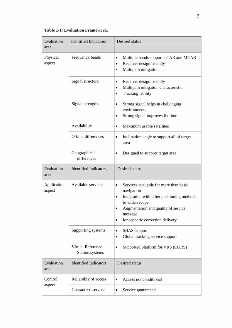
Table 1-1: Evaluation Framework. ............................................................................................ 7
Table 4-1: Frequency bands of different GNSSs ..................................................................... 27
Table 4-2: GNSS signals and received signal strength on Earth ............................................. 31
Table 4-3: GNSS orbital information ...................................................................................... 31
Table 4-4: BeiDou GEO satellites ........................................................................................... 32
Table 4-5: BeiDou IGSO satellites .......................................................................................... 32
Table 4-6: GNSS support in Australia for GNSS .................................................................... 42
Table B-1: Performance credit ranking .................................................................................. B-2

vii
Glossary BOC Binary Offset Carrier
BPSK Binary Phase Shift Keying
CBOC Composite Binary Offset Carrier
CDMA Code Division Multiple Access
CS Commercial Service
EGNOS European Geostationary Navigation Overlay Service
EU European Union
FDMA Frequency Division Multiple Access
GAGAN GPS Aided GEO Augmented Navigation
GBAS Ground Based Augmentation System
GEO Geostationary Earth Orbit
GLONASS GLObal NAvigation Satellite System
GNSS Global Navigation Satellite System
GPS Global Positioning System
GRAS Ground-Based Regional Augmentation System
GRR Galileo Ground Reference Receiver
GSS Galileo Sensor Station
GSO GeoSynchronous Orbit
HP High Precision
ICD Interface Control Document
ICG International Committee on GNSS
IGSO Inclined Geosynchronous Orbit
IOV In-Orbit Validation
IRNSS Indian Radio-Navigation Satellite System
ISRO Indian Space and Research Organisation
MBOC Multiplexed Binary Offset Carrier
MEO Medium Earth Orbit
MSAS MTSAT Spacebased Augmentation System

viii
OS Open Service
PPS Precise Positioning Service
PRN Pseudo Random Noise
PRS Public Regulated Service
PSK Phase Shift Keying
QPSM Quadrature Product sub-carrier Modulation
QZSS Quasi-Zenith Satellite System
RNSS Regional Navigation Satellite Systems
SA Select Availability
SAR Search and Rescue
SARSAT Search and Rescue Satellite Aided Tracking
SBAS Satellite-Based Augmentation Systems
SIS Signal In Space
SV Space Vehicle
TCAR Tri Carrier Ambiguity Resolution
US United States
WAAS Wide Area Augmentation System
1
Chapter 1 Introduction
1.1 Project background
1.1.1 GNSS background information
The current GNSS systems have been developed to provide competing alternate
Global Navigation Satellite Systems (GNSS), largely overlapping in functionality
but with limiting factors built into them to maintain strong control over who is
able to use the systems and at which level of accuracy. Some systems, such as the
US GPS system and Russian GLONASS are fully operational in terms of
available satellites, whereas European Galileo, Chinese BeiDou-2 Navigation
Satellite System (BDS) (formerly known as Compass/BeiDou-2), Japanese Quasi-
Zenith Satellite System and Indian Regional Navigational Satellite System
(IRNSS) are in their respective development and implementation phases.
The Global Positioning System (GPS), developed by the US Department of
Defence in 1973, was the first Global Satellite Navigation System in operation. It
was designed to provide the US military with a space based positioning service
more accurate than previous satellite based TRANSIT system, later developed
into project NAVSTAR (Eissfeller et al. 2001) and accurate enough to be used in
ballistic missile navigation in an era when the cold war between the United States
and the Soviet Union reached a stage of perceived threat of nuclear war. For that
reason the design parameters initially restricted GPS for military use only. After
an incident involving a civilian airliner invading then Soviet Union territory and
being shot down caused the US Government to release the GPS system to civilian
use in the belief that better tools would have helped to avoid such an incident
(Pellerin 2006). This civilian use was however limited by the exclusion of certain
information from the data content. This was established through coding and
encrypting part of the exclusive information and even introducing a deliberate

2
degrading of data, called "Selective Availability", which needed to be removed by
a decoding packet to achieve nominal accuracy.
The same perceived heightened threat of a nuclear war prompted the Soviet Union
to replace its accurate but slow TSYKLON submarine navigation system (Ristić
et al. 2010). This marked in 1976 the start of Globalnaya Navigatsionnay
Sputnikovaya Sistema (GLONASS), which was under the jurisdiction of the
Russian Aerospace Defence Forces. GLONASS also, like GPS, incorporates
deliberate error generation in its high precision signal in order to deny civilian
users, or the enemy, the more accurate GNSS service.
The European Union initially started to develop their GALILEO system as a
commercial enterprise for civilian use in 1999 (Roberts 2011) After some creative
marketing estimates, giving the project much greater return on investment than
was realistic, were discovered erroneous the project was close to being
abandoned. This was given further discouragement by the US opposing to the
Galileo project due to resulting inability to deny accurate positioning service in
times of conflict (Dawoud 2012). Ironically, this resulted in decision makers
realising that they cannot rely on GPS or GLONASS due to them being
potentially shut off at any time. In 2002 the Galileo project was agreed upon
(Dawoud 2012) by the European Union to be established and run by the European
Space Agency (ESA).
Similar to GPS and GLONASS, Galileo also has services with different levels of
accuracy available. The high precision data services are not, however, offered
based on military involvement but instead are driven by commercial agreements.
Chinese BeiDou-1 project was initiated by the Chinese Government in 1980. It
was initially developed as a regional system for the Chinese Government
(Dawoud 2012). It was different in concept to other GNSS systems in that it was
based on geo-stationary satellites positioned to service East Asia and Oceania.
China joined the Galileo project in 2004 (Hongwei et al. 2010) in order to gain
influence in a global civilian GNSS with some considerable funding. Soon after,
however, Chinese Government realised that Galileo was not developing in the

3
direction that China wanted (Dawoud 2012) and made a decision to develop
BeiDou further and enter into commercial, civilian market with it.
The resulting Compass/BeiDou-2, later renamed BeiDou-2, still maintains its geo-
stationary satellites but introduces additional satellites in the medium earth orbit
planes making it an autonomous global navigation satellite system.
The Indian Regional Navigational Satellite System (IRNSS) and Japanese Quasi-
Zenith Satellite System (QZSS) are Regional Navigational Satellite Systems
(RNSS), which both operate autonomously and use existing GNSS systems to add
functionality in operating in challenging urban environments and mountainous
regions. They use geo-stationary satellites and inclined geo-synchronous orbit
(IGSO) satellites to distribute their augmentation data (Roberts 2011). RNNS
systems do not however fall under the scope of this project.
1.1.2 Project context
Common to all GNSS systems is that long standing procedures and traditions do
not exist and much of the international guidelines are based on agreements
between nations and their respective agencies of authority. The resulting
allocations of frequencies and bandwidths have been contested at times and space
vessels have even been launched to confirm said frequencies to some extent
(Dawoud 2012).
The concept of global navigation satellite system has been implemented in
relatively similar fashions by all system designers. They are based on having an
accurate clock in the satellite and broadcasting of orbital information with a time
stamp down to receivers. This project, Evaluation of the performance of different
Global Satellite Navigation Systems (GNSS) for Australian GNSS users, will
focus on different physical and application details and specifications to evaluate
them in terms of practical relevance.
As stated earlier, some of the GNSS systems are operational and some in
development and implementation phase. This will make empirical testing of each
of them either very difficult or impossible using available resources.

4
The evaluation of GNSS systems includes how each provides a service to an
Australian user. This includes topics like physical parameters of the signals, the
geographical and orbital characteristics and availability. Furthermore it includes
topics about services, integrated and external, and applications such as integration
and customisation potential, global positioning services as well as distribution of
reliability and availability of service. It also seeks to uncover any Governmental
policies and guidelines that may be relevant to the use of a GNSS system in
national legislature and regulations.
1.2 Project aims and objectives
1.2.1 Project aims
This project aims to find tangible differences in GNSS systems currently available
and in planning from an Australian GNSS user point of view. It seeks to uncover
aspects of design or physical characteristics that will differentiate between GNSS
systems, in particular when used in Australia.
1.2.2 Project objectives
The project objectives include:
Gain understanding of systems by performing a literature review
Research technical specifications for differences in GNSS systems
Research geographical differences of GNSS systems
Develop evaluation assumptions, methods and criteria
Draw conclusions
1.3 Scope and assumptions of the project
This project will evaluate information on systems and designs against an
evaluation framework. It determines that framework based on published work on
feature relevancies.
This project will assess information and outcomes of studies published previously
with focus on the relevance of those results but will not seek to verify them.

5
The project is supported by field tests when appropriate to verify theories and
confirm behaviour estimates in the Australian context.
Assumptions will be formulated to both limit the scope in the context of
"Australian User" as well as overcome the issues with non-verifiable information,
such as system features that are published but not implemented and therefore
subject to scrutiny.
The evaluation framework from an Australian perspective will be restricted to the
use of GNSS for positioning purposes with emphasis on the surveying discipline.
Furthermore, the framework is limited to include features and technical
differences of the GNSS systems that provide a basis for evolutionary applications
and are likely to be exploited by the surveying discipline.
1.4 Evaluation framework
Evaluation framework provides a focus on the evaluation by giving it a scope of
particular issues of importance, a set of goals or desired outcomes within those
issues and a set of criteria in determining the level of comparative impact to the
topic.
Due to the rapid changes in implementation progress of particularly Galileo and
BeiDou, some aspects of evaluation will be speculative as to the interoperability
status with augmentation systems.
Overall, assumptions have to be made about exclusive use of any given GNSS
system:
The nature of comparative evaluation demands that features of individual
systems be assessed on their stand alone merits even if that exclusive use
is unlikely.
Assumptions regarding the adoption of various supported services will
have to be made to include the use of potential relevant technical
advantages, regardless of their commercial viability in surveying industry.
The user will be able to use only one GNSS system.
The features of GNSS systems are assessed as if operational.
Receiver design will allow use of all features.

6
Table 1-1 depicts the elements of each evaluation areas:
Physical; features of the signals and equipment as well as methods and
physical means of signal transmission.
Application; services and applications that the signals enable and support.
Control; characteristics of the system administration and user
authorisation.
These areas as well as identified indicators have been derived from the perceived
focus in review literature.
1.5 Structure and outline of the report
This report starts off with the introduction to the project and its historical
background regarding its major area of focus to conceive the objective of the
project.
That is followed by the review of significant perspectives expressed by industry
experts in the area of GNSS features and their practical effects on real life
surveying. Consequently the evaluation framework was determined to enable
comparative assessment and evaluation.
A literature review was conducted to ascertain the nature and trends of research in
the area of GNSS development and future outlook. This revealed features that are
the most likely to contribute to finding details of the identified indicators of
comparative excellence.
The data collection was performed along with the literature review resulting in
outlining of the features and respective relative strengths and weaknesses of each
GNSS as well as attempting to classify the quality of that data. An evaluation
framework table of these strengths, weaknesses and qualities of the source of the
data was formulated to lay out the final assessment of the different GNSS
systems.
Finally, these results were discussed and conclusions drawn.
7
Table 1-1: Evaluation Framework.
Evaluation
area
Identified Indicators Desired status
Physical
aspect
Frequency bands Multiple bands support TCAR and MCAR
Receiver design friendly
Multipath mitigation
Signal structure Receiver design friendly
Multipath mitigation characteristic
Tracking ability
Signal strengths Strong signal helps in challenging
environments
Strong signal improves fix time
Availability Maximum usable satellites
Orbital differences Inclination angle to support all of target
area
Geographical
differences
Designed to support target area
Evaluation
area
Identified Indicators Desired status
Application
aspect
Available services Services available for more than basic
navigation
Integration with other positioning methods
to widen scope
Augmentation and quality of service
message
Ionospheric correction delivery
Supporting systems SBAS support
Global tracking service support
Virtual Reference
Station systems
Supported platform for VRS (CORS)
Evaluation
area
Identified Indicators Desired status
Control
aspect
Reliability of access Access not conditional
Guaranteed service Service guaranteed

8
1.6 Chapter summary
This project seeks to, by means of research, find aspects of design, physical
limitations or advantages that will provide a level of differentiation between
current GNSS systems. It further seeks to quantify the practical consequences of
those potential differences in the context of Australian GNSS user.

9
Chapter 2 Literature review
2.1 Introduction
"In the next few years, surveyors using high productivity, real-time
kinematic (RTK) positioning and indeed all other precision positioning
users will be faced with a barrage of new global navigation satellite
system (GNSS) signals from GPS, GLONASS, GALILEO and possibly
COMPASS/Beidou2 as well as Satellite Based Augmentation Systems
(SBAS) signals and Regional Navigation Satellite Systems (RNSS).
New receivers with enhanced capabilities will enter the market and the
old days of choosing which colour GPS receiver will be replaced by a
myriad of new considerations." (Roberts 2011, p1)
In the wake of the realisation that the high precision services from systems like
GPS and GLONASS will not be reliable in times of conflict many national
instances have decided to secure their navigation needs by implementing
alternative systems. This has been done either by introducing completely self-
contained GNSS systems like Galileo and BeiDou-2 or by implementing
additional resources to GPS and GLONASS base services to form Regional
Navigation Satellite Systems (RNSS) or Space Based Augmentation Systems
(SBAS).
To assess the differences and advantages or limitations between any two or more
systems we need to gain understanding of the development of each system.
2.2 The physical perspective
The GPS system employs 24 active satellites in 6 unevenly distributed orbital
planes with 4 satellites in each plane. This provides with a better coverage of the
northern hemisphere. Each orbit is inclined at an angle of 55° to the astronomical

10
equatorial plane. The orbits are ellipses (Cojocaru et al. 2009) with small
eccentricity (e≈0.003) with flight path length of the flight path for each satellite is
26,560km at an orbital radius of approximately 26,600 km and the travel time is
11h 58min (Ristić et al. 2010). This design aims at having always a minimum of 4
satellites visible at any location at any point in time.
The GPS system uses Code Division Multiple Access (CDMA) technique, where
each and every satellite transmits the same two carrier bands (Lewandowski et al.
2009). The satellites initially transmitted Coarse/Acquisition (C/A) code signals
on the L1 (1575.42MHz) band and the P(Y or Precise) code on the L2
(1227.60MHz) band (Eissfeller et al. 2001). After a modernization phase began in
2005 more bands were utilised, L1M and L2M for military use and L2C for a new
civil signal (Eissfeller et al. 2001) as well as new L5 band signal (1176.45MHz)
(Roberts 2011). The clock accuracy is one of the most important factors in
achieving positioning accuracy and Larson et al. state (2000) "The formal error
for the carrier-phase clock estimates are on the order of 125x10-12
s". GPS system
uses WGS-84 coordinate reference frame which closely resembles the
International Terrestrial Reference Frame (ITRF) and GPS time (Chen et al.
2009).
The Russian GLONASS system is currently fully operational with 24 active
satellites in 3 evenly distributed (120⁰) orbital planes. The 8 satellites in each
plane are also evenly distributed in their circular orbits with radii equal to
approximately 25,480 km, which implies an orbital period of 11h15m (sidereal
time) and a flight altitude of around 19,100 km (Cojocaru et al. 2009). This
arrangement guarantees 5 satellites visible at any location at any point in time.
First generation GLONASS system uses Frequency Division Multiple Access
(FDMA) technique in which two individual carrier frequencies are assigned to
each satellite, but the PRN-codes are the same for all satellites (Lewandowski et
al. 2009). The GLONASS system operates on same L1 and L2 bands as GPS with
L1 frequencies between 1602 and 1615.5 MHz and L2 frequencies between 1246
and 1256.5 MHz (Dawoud 2012). The latest development introduces Glonass-K1
satellites in 2012 with CDMA technique on new L3 band (1202.025MHz) and
later in 2013 the Glonass-K2 satellite brings CDMA to existing L1 band (Stupak

11
2010). The GLONASS satellites initially carried Caesium clocks with daily
frequency stability of 5x10-13
(Eissfeller et al. 2001) but with second generation
implementation these were replaced by rubidium clocks.
The GLONASS system uses ParametryZemli 1990 (PZ90) coordinate reference
frame which also closely resembles the International Terrestrial Reference Frame
(ITRF) and UTC (SU) time (Chen et al. 2009).
The Galileo will, when fully operational, consist of a constellation of 27 active
satellites. These satellites are spaced around the plane in three circular medium
earth orbits with radii equal to around 29,600km and inclination of 56⁰ to the
equatorial reference plane. They have an orbital period of 14 sidereal hours
(Cojocaru 2009). Galileo constellation guarantees that at any point on the earth,
there will be at least 6 satellites in the view (Dawoud 2012). The combination of
the orbital inclination and the flight altitude of the satellites will considerably
increase the coverage of the Polar Regions (Cojocaru 2009).
Galileo will transmit its ten navigation signals in the frequency ranges of 1164 -
1215 MHz (for E5a and E5b), 1215 - 1300 MHz (for E6) and 1559 - 1592 MHz
(for E2-L1-E1). The E2-L1-E1 range includes the GPS frequency band L1. An
additional frequency range of 1544.05-1545.15 MHz is defined as Search and
Rescue (SAR) uplink as well as frequency range of 406.0-406.1 MHz as SAR
downlink frequencies. All Galileo satellites will transmit using the same nominal
frequency, utilising Code Division Multiple Access (CDMA) which is compatible
with the GPS approach (Dawoud 2012).
The Galileo satellites generate its signals using passive hydrogen masers. It is
very stable and its accuracy can be stated by saying it would lose only one second
in three million years (ESA 2012). They also carry rubidium atomic frequency
standards for backup. The stability of the rubidium clock using the same analogy
indicates it would lose three seconds in one million years.
The Galileo system uses Galileo Terrestrial Reference Frame (GTRF) which is
compatible with ITRF2005 and it uses Galileo system time (GST). GST start
epoch is 00:00 UT on August 22nd 1999. At this epoch, GST shall be ahead of

12
UTC by 13 s and will not apply leap seconds. GST is therefore “aligned” to GPST
(Dalporte 2009)
The Beidou-2 system will consist of 35 satellites including 5 geostationary orbit
(GEO) satellites, 5 in highly inclined (55⁰) geosynchronous orbits (IGSO) and 24
medium Earth orbit (MEO) satellites. The 24 satellites will be evenly distributed,
45° separated in argument of latitude, in 3 orbital planes with an inclination angle
of 55° (Chen et al. 2009). They will offer complete coverage of the globe orbiting
flying at an altitude with semi-major axis of 27840km (Dawoud 2012).
As at June 2012, 4 of the 5 GEO satellites are operating whilst one has ceased
transmitting, all 5 IGSO satellites are fully operational and can already be
employed for standalone positioning in South East Asia and Oceania. The only
MEO satellite in orbit, whilst still transmitting, has developed a clock problem
and cannot be relied upon for positioning (Montenbruck et al. 2012). The MEO
satellites have an orbital period of 12h50m. The BeiDou-2 signals are transmitted
in three bands; B1 (Equivalent of Galileo E2) at 1,561.098MHz, B3 (Equivalent
of Galileo E6) at 1,268.520MHz and B2 (Equivalent of Galileo E5b) at
1,207.140MHz. The signal division technique for BeiDou-2 is CDMA.
The primary frequency standard of the Compass/Bei-Dou-2 navigation payload is
based on Rubidium clocks (Mallette et al. 2010). For redundancy purposes, all
satellites are equipped with clocks of different origin, except for COMPASS-M1,
which builds exclusively on Chinese technology (Montenbruck et al. 2012).
Frequency Stability according to Gao et al. (2011) is 8.47×10⁻¹⁵
over 7 days.
The BeiDou-2 system uses Beijing 1954 for its coordinate frame. The
COMPASS/BeiDou system time (BDT) adopts the length of a second in
international atomic time as its basic unit and uses the continuous counting
method with ‘week’ and ‘second of the week’. BDT is broadcast in the navigation
message files. The starting point of BDT is at 00:00 UTC Jan 1st, 2006, and there
is no leap second in the BDT system (Gao et al. 2011).

13
2.3 The application perspective
The GPS system transmits its navigation message in two codes, the
Coarse/Acquisition (C/A) providing Standard Positioning Service (SPS) and the
encrypted Precise-code (P) providing Precise Positioning Service (PPS).
Furthermore, a new M-code incorporating the Selective Denial spoofing technique
of the C/A code is included (Ristić et al. 2010). Although there are many services
to complement the GPS system, no additional services are included in the GPS
system itself and for instance augmentation services are completely external to the
GPS architecture (Rizos et al. 2005).
Glonass runs a similar system to GPS with Standard Precision Service (SP) and
High Precision Service (HP) with C/A and P-codes respectively. Importantly,
each service is run on both L1 and L2 bands allowing dual frequency receiver
civilian use (Ristić et al. 2010).
The Galileo runs five different services (ESA 2011):
Galileo Open Service (OS), open, free service with guaranteed accuracy
but no quality or integrity information
Galileo Commercial Service (CS), adds two encrypted and customer
configurable signals to allow external service integration to CS
Galileo Public Regulated Service (PRS) is an Access-Controlled service
intended for law enforcement and government authorities of European
Union offering improved continuity of service in the presence of
interfering threats
Galileo Safety of Life (SoL) contains signal integrity information at global
level as opposed to other systems using SBAS to provide for integrity
Galileo Search and Rescue Service (SAR/Galileo) provides SAR service
via detection of Emergency Position Indicating Radio Beacons (EPIRBs)
as well as via a return link from the SAR operator to the distress emitting
beacon
BeiDou-2 supports both global worldwide services and regional services. Under
the global services it offers Open Service similar to GPS and Authorized Service
for Military use. Under the regional services users are provided with wide area
14
differential services including ionosphere grid data and intersystem time offsets
(Montenbruck & Steigenberger 2013).
GNSS systems are widely supported and utilised by various commercial and non-
commercial service providers. They are of both global and regional nature. Precise
Point Positioning (PPP) service is an example of a global service where
institutions around the world provide post processing of observation data gathered
anywhere in the world, often free of charge, over the internet. Although it may be
reasonable to expect that all systems will be supported at a later stage, according
to Gakstatter (2013) the Australian AUSPOS PPP-service does not get a mention
for support for other than GPS system, where most others are reported to include
GLONASS data processing. No information was given on Galileo or BeiDou-2.
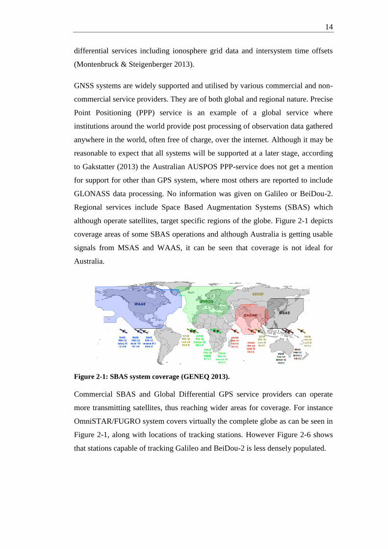
Regional services include Space Based Augmentation Systems (SBAS) which
although operate satellites, target specific regions of the globe. Figure 2-1 depicts
coverage areas of some SBAS operations and although Australia is getting usable
signals from MSAS and WAAS, it can be seen that coverage is not ideal for
Australia.
Figure 2-1: SBAS system coverage (GENEQ 2013).
Commercial SBAS and Global Differential GPS service providers can operate
more transmitting satellites, thus reaching wider areas for coverage. For instance
OmniSTAR/FUGRO system covers virtually the complete globe as can be seen in
Figure 2-1, along with locations of tracking stations. However Figure 2-6 shows
that stations capable of tracking Galileo and BeiDou-2 is less densely populated.

15
Figure 2-2: OmniSTAR/FUGRO coverage (OminSTAR 2013).
Global tracking is also an aspect of support for a GNSS system. One of the
purposes for global tracking is determination of inter-system biases (IGS 2013)
and that implies tracking of all systems. The Multi-GNSS Experiment (MGEX)
coverage map, Figure 2-3 below, depicts tracking stations around the world.
Figure 2-4 and Figure 2-5 show stations capable of tracking Galileo and BeiDou-2
satellites respectively. Cooperative Network for GIOVE Observations (CONGO)
is operated by Deutsches Zentrum für Luft- und Raumfahrt (DLR ,The German
Aerospace Center), Bundesamt für Kartographie und Geodäsie (BKG, The
Federal Agency for Cartography and Geodesy), and Deutsches
GeoForschungsZentrum (GFZ, German Research Centre for Geosciences). It
provides tracking information for GIOVE satellites but some tracking stations also
carry out tracking of GPS and GLONASS satellites. CONGO tracking stations are
depicted in Figure 2-7 with GLONASS capable stations signified with red
squares.
Virtual Reference Station systems, such as Continually Operating reference
Station systems in Australia may or may not support other GNSS than GPS but
literature is scarce with the smartnetaus twitter feed stating: "new Trimble
firmware enables use of @smartnetaus CORS corrections with Glonass enabled
units" (2013).

16
Figure 2-3: MGEX stations (IGS 2013).
Figure 2-4: MGEX stations with Galileo tracking capability (Tegedor et al. 2013).
Figure 2-5: MGEX stations with BeiDou-2 tracking capability (Tegedor et al. 2013).

17
Figure 2-6: FUGRO stations with Galileo and BeiDou-2 tracking capability
(Tegedor et al. 2013).
Figure 2-7: CONGO tracking stations (TUM 2013)
2.4 The control perspective
As Eissfeller et al. (2001) and Ristić et al. (2010) have stated GPS and
GLONASS, respectively, have been developed with a sovereign military control.
Dawoud (2012) mentions that BeiDou-2 is aimed at commercial markets whilst
supremely run by the Government of China. Galileo on the other hand is a civilian
enterprise (Roberts 2011) with dedicated services for Government use.
The previous statements imply, and in the case of GLONASS have been
acknowledged, that service from a GNSS is not guaranteed, and indeed may be
turned off at any time. This will have consequences in decision making for
institutions which rely on un-interrupted reliable GNSS services.

18
2.5 Australian perspective
Literature about the impacts of different GNSS systems to Australian users seems
focused on overall potential and real benefits provided by multiple GNSS systems
employing new frequency bands. According to Roberts (2011), the new signals
are more powerful and improve initialisation time in dual frequency RTK as well
as suit Australian geographical location particularly well.
Reporting of benefits of an individual GNSS system over the others has been
limited to outlining affiliations and partnerships between said GNSS and
augmentation service providers such as the Japanese Quasi-Zenith Satellite
system and the US WAAS supporting GPS whilst European EGNOS supports
Galileo (Roberts 2011).
"More signals however will mean a stronger solution as a result of
improved dilution of precision and less likelihood of dropouts due to a
lack of satellites. Australia is geographically well situated to benefit from
the increase in new signals… Perhaps mission planning will become
redundant" (Roberts 2011).
From an Australian perspective the regional component of BeiDou-2 system
offers advantages in improved availability and Geometry Dilution of Precision
(GDOP), due to presence of additional, regional satellites, as well as availability
of differential services (Chiang et al. 2010).
Literature about supporting services paint a picture of GPS-centric practice with
some Glonass support as laid out in previous chapter covering application
perspective.
2.6 Conclusions
The various systems use a multitude of frequency bands and coding systems but
can operate in a compatible manner. Some of the current equipment can receive
all signals but The US Department of Defence has stated that they will not support
the legacy L1 (C/A) / L2 (P/Y) signals after 2020 which means that surveyors will
have to upgrade to L2C or L5 capable equipment to guarantee high precision

19
performance (Roberts 2011). With GNSS systems still in development phase,
BeiDou-2 is the only navigation satellite system offering a sufficient number of
signals-in-space for continuous navigation in at least the Asia-Pacific region
(Montenbruck et al. 2012).

20
Chapter 3 Methodology
3.1 Introduction
To ascertain how different characteristics of each GNSS system affect the
Australian user the theoretical information is assessed to reveal any potential
contributing factors. The prevailing profile of an Australian GNSS user needs to
be clarified in terms of potential use of different navigation data available through
the GNSS systems. A study of assessing this will be undertaken simultaneously
with previous task due to likely overlapping of topics. Also a perspective of the
professional GNSS bodies is outlined in this context.
The necessary field activities, if deemed useful given the availability of
applications exploiting specific features is uncertain, were planned based on
availability of equipment and necessary access to all GNSS information. As the
information was gathered it became evident that field experiments would serve
only a limited purpose due to two of the GNSS systems reviewed running in
limited or test mode as well as, for testing probable differentiating features, an
unrealistic need of resources such as experimental receivers and simulation
equipment and software.
The project needed a methodology that could be implemented within the scope of
the project, would fulfil the requirements of finding real and measurable
differences and allow for the assumptions necessary to perform the evaluation.
3.2 Methodology of evaluation
Given the limitations in access to real measurement data, some assumptions
needed to be made. The task of formulating these, and any other, assumptions was
required to both limit the scope and give the project a realistic context. This
became the first step in the methodology of the project.
21
Assumptions made were:
The Australian user is limited to one GNSS.
The Australian user perspective was limited to surveying in Australia.
All GNSS assessed are fully operational.
Receiver technology does not pose any limitations.
The next step was to research literature for information that would contribute to
identifying indicators that can be used in evaluating benefits and limitations of
each GNSS, specifically from an Australian user's perspective. This was
performed by researching papers from conferences and seminars for topics of
special interest. This provided an insight into which areas of technology and
applications the experts in the industry expected to be relevant when comparing
the performance of each GNSS. Further research was conducted into thesis
produced and reports on subjects that gave new evidence in theories and
technological predictions. Furthermore, research was extended to international
and national institutions and their work to gain understanding in the areas of
compatibility and inter-operability of the GNSS. A list of identified indicators was
compiled based on this research and will be put in a matrix for evaluation.
The data to be evaluated was gathered from previously mentioned literature
research and no data collection from field experiments was performed.
Classifying the information by quality and by relevance was performed along with
previous formulation of identified indicators. This was done by sorting the data
into groups of:
research on actual data and performance
research on simulations of performance based on published data and
known parameters
research on theoretical implications of expected behaviour within known
context
The relevance was derived to from weighting and emphasis given to various
differentiators by experts in the field.

22
Evaluating the parameters against the evaluation framework was then performed
to determine the effectual differences in the GNSS systems and the result of the
evaluation, weighted by data classification, was formulated.
This was followed by review of the objectives and how the results contribute to
achieving those objectives.
Review of assumptions was then overlayed to the results and objectives to identify
any discrepancies as well as circular structures and multiplication of instances of
weighting of results.
Finally, conclusions were formulated based on evaluation against the evaluation
framework along with caveats regarding the objectivity of weightings.
3.3 General framework for evaluation
The evaluation framework falls under 'competition benchmarking' (Steudler
&Kaufmann 2002). This means that rather than evaluate whether a system feature
gives the best possible outcomes, an outline on how the outcome of that feature
compares with other systems is given.
Historical review of evaluation frameworks reveals that an evaluation of GNSS
systems is dominated by specific scenarios or the performance of combined
GNSS systems. The evaluation framework for this project adheres to the
competition benchmarking criterion but also looks at a broad range of topics.
The evaluation framework was chosen to provide a focus on the evaluation that
reflects the needs of an Australian user. It was designed to focus on real outcomes
and results of the various differentiating features and factors of each GNSS.
3.4 Evaluation framework structure
The evaluation framework was given a structure that divides the topics into three
categories based on the nature of those topics. The resulting categories, reflecting
aspects of each, were physical, application and control. The physical aspect looks
at features of the signals and equipment as well as methods and physical means of
signal transmission. The application aspect considers what services and
23
applications each GNSS system enable and support. Finally, the control aspect
looks at how the use of each GNSS system is governed and how that might affect
decision making in Australia.
A matrix of identified indicators was built with ranking of features as well as
rudimentary classification of the quality of the data collected. Quality was decided
to be determined by the nature of study behind the data, real testing versus
simulation or theoretical examination, as well as the consensus relating to the data
amongst academics.
3.5 Risk Assessment
Risk Assessment was performed on the basis that outside of everyday risks no
specific risks were anticipated. The risk of consequences of misrepresentation of
data and implied, unqualified recommendations was deemed to be low.
3.6 Ethics
This project was not likely to encounter the topic of ethics either in its preparation
and field work, nor its publication. The possible global political opinions of
contributing literature were not relayed to the project output, nor were any offered
by the author.
3.7 Conclusions
As a conclusion, the methodology of evaluation is pragmatic and simplistic, with
the aim of stating the outcomes in an un-ambiguous manner.

24
Chapter 4 Evaluation
4.1 Introduction
Evaluating GNSS systems is about finding different features in each of them and
assessing the impact they are likely to have on an Australian user. Many of the
features impact same or similar aspect of the usability of a system. It was
necessary to give the evaluation a structure that enabled evaluation to be divided
into smaller entities that were logical and easy to understand. This resulted in
division into physical, application and control aspects.
4.2 Evaluation of physical aspects
4.2.1 Frequency bands
The various GNSS systems operate in the L - Band frequency range which sits
between 1GHz and 2GHz. Figure 4-1, Figure 4-2 and Figure 4-3 show the
distribution within that frequency range covering a number of different carriers
and bandwidths. It is, however, fortunate from the receiver manufacturing point of
view that they can be grouped to two bands. The first ranges from E5/L5 to E6
and the second from Compass L1 to Glonass G1. These two bands can be handled
by a single receiver design. Using stacked patches in antenna design multiple
bands can be received albeit with less gain and bandwidth (Dempster & Hewitson
2007).
This shared frequency range also lends itself to more interoperability of signals as
well as manufacturers exploiting them all with mass produced devices. If
anything, this seems to encourage multi-GNSS receivers, negating the need to
choose between systems.

25
There are performance differences due to selection of carrier frequencies
nevertheless. Three-carrier ambiguity resolution can be seen as an improvement to
RTK baseline length for high accuracy surveying. With gap-bridging concept,
TCAR uses two closely spaced (super-widelane) and two widely spaced
(widelane) carrier frequencies to create virtual wavelengths and frequencies
(Werner & Winkel 2003). These are then subjected to mathematical formulae
along with first estimation of the satellite to receiver line-of-sight range from one
code range measurement to obtain first a super-widelane and then widelane
ambiguity fix.
Figure 4-1: GNSS frequency band L1 (Stupak 2008)
Figure 4-2: GNSS frequency band L2 (Stupak 2008)

26
Figure 4-3: GNSS frequency band L5 (Stupak 2008)
The separation of bands plays a part in the success rate of ambiguity resolution
(AR). Werner and Winkel (2003) studied the theoretical AR success rate between
GPS and Galileo systems and found that, of all possible band combinations and
using specific set of assumptions regarding the signal structures, carrier-to-noise
ratios and the multipath environment, using E5ab for code and base signal, E6-
E5ab for Super-Widelane and L1-E5ab for Widelane yielded a 100% success rate
overall. This compared favourably with GPS which only has three bands and
therefore les potential combinations.
Werner and Winkel (2003) point out that "an important pre-condition for the
performance of this algorithm is that there are no or only small multipath effects
present, because otherwise, these systematic effects will destroy this 'gap-
bridging' concept". This is likely to dilute the potential of TCAR, despite the lure
of its distance independency, as a realistic alternative for other than wide open
areas. Another limiting factor for TCAR is that at this time availability of mobile
receivers capable of performing TCAR is to be announced.
In conclusion, all GNSS systems offer suitable frequency bands for current GNSS
receivers. The lack of civilian signal in GPS L2 band has necessitated semi-
codeless tracking development for receivers but this is a stable situation and
should in fact disappear in the future. The Galileo enjoys an advantage in band
distribution that enables better exploitation of some techniques, such as Tri
Carrier Ambiguity Resolution (TCAR). The BeiDou-2 system lacks published
information to formulate reliable conclusions but it shares the E6 band frequency
with Galileo and may have an advantage in TCAR behaviour, see Table 4-1.

27
Table 4-1: Frequency bands of different GNSSs (Rodríguez 2008).
System GPS GLONASS Galileo Compass
Frequency Band L1 L1 E1 B1
Centre Frequency 1575.42 MHz 1602 MHz 1575.42 MHz 1561.098 MHz (B1)
1589.742 MHz (B1-2)
Frequency Band L2 L2 - -
Centre Frequency 1227.60 MHz 1246 MHz - -
Frequency Band L5 - E5a -
Centre Frequency 1176.45 MHz - 1176.45 MHz -
Frequency Band - - E6 B3
Centre Frequency - - 1278.75 MHz 1268.52 MHz
Frequency Band - L3 E5b B2
Centre Frequency - 1201 MHz 1207.14 MHz 1207.14 MHz
4.2.2 Signal structures
The signal structures of various GNSS systems vary substantially more than the
frequencies. Three of the four GNSS, GPS, Galileo and BeiDou, use Code
Division Multiple Access (CDMA) modulation to identify each space vehicle
message within the broadcast stream. Glonass uses historically Frequency
Division Multiple Access (FDMA) modulation (which is depicted as a group of
frequencies in Figure 4-1), with each space vehicle allocated one out of 16
frequencies, thus providing identification to the control system. Even though there
are 16 frequencies, the full constellation is planned to consist of 18 space vehicles
(SV). This has been made possible by allocating same frequencies to antipodal
SVs (Misra 2013). Glonass are modernising the SVs and is testing and will be
implementing a CDMA method as well.
This distinction is historically due to FDMA providing (previously) better security
protection thanks to the improved Spectral Separation Coefficient (SSC) of
FDMA (Rodríguez 2008). This advantage has however vanished with improved
security of CDMA via cross-correlation of the employed codes. Inclusion of
FDMA will make receiver design more costly and move by Glonass towards use
of CDMA is seen as part of their move to commercialising Glonass. From the user

28
point of view, as long as receiver can decode both modulation methods, there is
no practical difference.
Whilst the actual signal structures of different GNSS systems is beyond this
report, some pieces of information can give insight into how they affect the user.
The signal structure of each GNSS system contributes to some extent to the
success of the tracking of the signal. For example, as Eissfeller et al. (2001) state,
the navigation data in Galileo system is only modulated on the I-Component,
leaving the Quadrature-Channel free of additional phase shifts (Galileo E1 In-
Phase and Quadra-Phase channels can be seen in Figure 4-4). This leads to a
coherent, i.e. more robust phase tracking at a lower Signal-to-Noise level.
Chipping rates (signal pulse rates) are to some extent decided with demands from
the requirement for interoperability and legacy concerns between different GNSS
systems in mind (Roberts 2011). The Galileo system, although free from
compelling design restrictions, chose to make its E1-band compatible to GPS L1-
band to enable use of legacy L1 receivers.
In general higher chipping rates are reported by each GNSS system literature to
yield higher accuracy levels in positioning. To explain this Roberts (2011, p. 8)
states: 'Chipping rate defines the resolution to which a raw measurement can be
made. So the L5 (or E5) with a 10.23Mhz chipping rate will be a more precise
measurement than the L1 C/A (or E1) at a 1.023Mhz rate'. He continues to add
(citing Avila-Rodriguez et al, 2008; Dempster and Rizos, 2009) that higher
chipping rates require more transmission power and more expensive receiver
design.
With various Binary-Offset Modulation (BOC) types, however, spectral
separation properties are reported to improve by lower chipping rates (Lohan et al.
2005). The main advantage of a BOC-modulated signal over binary phase shift
keying (BPSK) signal is its spectral-shaping capability, which allows a good
separation between old and new GPS and Galileo signals (Lohan et al. 2005). This
is not however a point of difference since all four GNSS systems are either using
or planning signals modulated by BOC and using similar chipping rates but may
become a differentiator if receiver limitations exist in this respect.

29
Figure 4-4: Galileo E1 spectrum, (Rodríguez 2011)
In conclusion, signal structures lend themself to various advantages in technique
exploitation. Higher chipping rates are being introduced to all GNSS systems and
Binary Offset Modulation in various forms is included in all GNSS systems, at
least in some message types. The FDMA used by GLONASS no longer enjoys a
security benefit due to the cross-correlation of codes modulated in CDMA. The
FDMA modulation of some GLONASS SVs causes some cost burden towards
receiver design. This has however stabilised with virtually every receiver
manufacturer offering a product. The Quadrature-Channel, being free of
additional phase shifts, leads to a coherent, i.e. more robust phase tracking at a
lower Signal-to-Noise level and should prove a benefit.
4.2.3 Signal strengths
Signal strengths for different GNSS systems reported by respective Interface
Control Documents (ICD) are presented in User Received Power. See below in
Table 4-2 the values compiled by de Bakker (2007) showing no significant
differences between systems. The BeiDou data is not present in the table but the
figures according to Rodríguez are -163dBW for all three bands B1, B2 and B3
(2011). As stated previously, signal structure may contribute to usability of signal
and tracking characteristics in particular.

30
Table 4-2 shows also the improved user received signal power yielded by more
powerful Galileo E5 and GPS L5 signals. This will improve the tracking of the
signal in areas where obstacles hinder the reception (Roberts 2011).
GPS and Galileo are enjoying an advantage in received signal strength in L5 and
E5-E6 bands respectively with a nominal difference.
4.2.4 Availability
GNSS availability is a concept that consists of the number and distribution of
useful satellites, the required satellite elevations for a particular scenario and, with
perhaps less significance, the potential authoritative control of the systems. In
essence it means the percentage of time the signal is available to the receiver in
any given scenario.

31
Table 4-2: GNSS signals and received signal strength on Earth (de Bakker 2007)
3. Minimum received power with a 3dBi gain linearly polarized antenna for a satellite with a minimum of
5 degrees elevation.
4. Minimum received power with a 0dBi gain ideally matched antenna for a satellite with a minimum of
10 degrees elevation.
Table 4-3: GNSS orbital information, source Chen et al. (2009)
GPS GLONASS Galileo BeiDou (MEO)
Number of SV 31 24 27 27
Orbital planes 6 3 3 3
Inclination 55º 64.8º 56º 55º
Table 4-3 above outlines the basic orbital characteristics of each GNSS (in case of
BeiDou, the Medium Earth Orbit (MEO) satellite component). BeiDou also has 5
Geostationary Satellites positioned strategically in the region (see Table 4-4) and
3 Inclined Geosynchronous Orbit (IGSO) satellites (see Table 4-5).
32
Table 4-4: BeiDou GEO satellites, source Chen et al. (2009)
Satellite Launch Date Position
BeiDou-1A 31-Oct-2000 140°E
BeiDou-1B 21-Dec-2000 80°E
BeiDou-1C 25-May-2003 110.5°E
BeiDou-1D 3-Feb-2007 58.75°E
BeiDou-1E TBD 160°E
Table 4-5: BeiDou IGSO satellites, source Chen et al. (2009)
Semi-major Axis [Km] 42164
Inclination [Deg] 55
Eccentricity 0
RAAN 0°, 120°, 240°
Argument of perigee 187.6°, 67.6°, 307.6°
From an Australian user's perspective availability is determined by available
satellites in Australian sky. This varies according to the number of satellites as
stated above and their orbits.
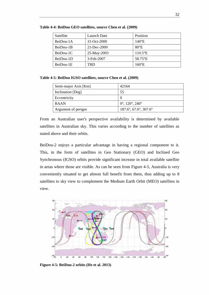
BeiDou-2 enjoys a particular advantage in having a regional component to it.
This, in the form of satellites in Geo Stationary (GEO) and Inclined Geo
Synchronous (IGSO) orbits provide significant increase in total available satellite
in areas where those are visible. As can be seen from Figure 4-5, Australia is very
conveniently situated to get almost full benefit from them, thus adding up to 8
satellites to sky view to complement the Medium Earth Orbit (MEO) satellites in
view.
Figure 4-5: BeiDou-2 orbits (He et al. 2013)

33
4.2.5 Orbital differences
Users in higher latitude areas, such as areas in the North of Canada, Alaska,
Europe, Russia as well as Antarctica, even Southern parts of Australia to some
extent, obtain better GLONASS availability and consequently better derived
dilution of precision (DoP) than users of GPS, Galileo or BeiDou-2 (Eissfeller et
al. 2001). This is due to the high inclination angle of GLONASS; 64.8 degrees
compared to 55 degrees for GPS and BeiDou-2 as well as 56 degrees for Galileo.
This will obviously affect an Australian user depending on the latitude they are in.
For GPS, Galileo and BeiDou-2 a user slightly south of Tasmania, at latitude -45
degrees, would be able to observe satellites all the way to northward masking
angle of, say, 10 degrees but would be subjected to a de facto southward masking
angle of approximately 76 degrees and the north-south sky view is approximately
105 degrees (see Figure 4-6). Using GLONASS the scenario changes so that the
de facto southward masking angle is approximately 63 degrees and the north-
south sky view is approximately 120 degrees (see Figure 4-7).
Figure 4-6: Tasmanian user's GPS, Galileo and BeiDou-2 sky view North-South

34
Figure 4-7: Tasmanian user's GLONASS sky view North-South
4.2.6 Geographical differences
Geographically, the focus of each GNSS system has been in the areas of
controlling bodies, North America for GPS, Russian Federation for GLONASS,
Europe for Galileo and China for BeiDou-2.This is evident in the distribution of
control stations.
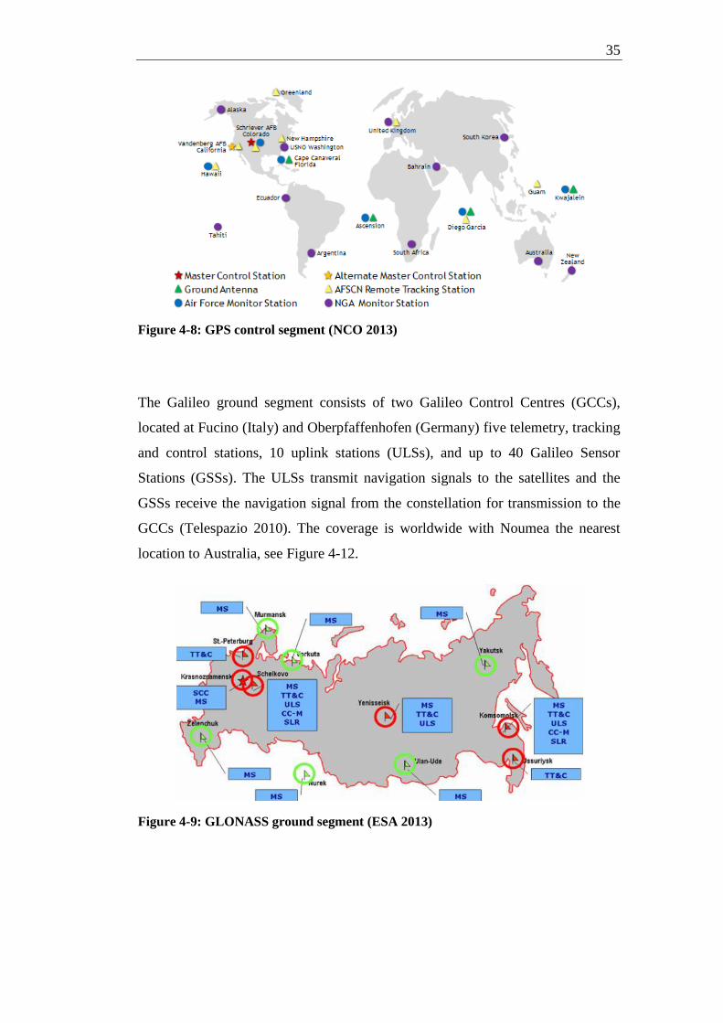
The GPS control segment, depicted in Figure 4-8, is distributed well around the
globe and the Ground Antennas, green triangles in the map, enable continuous
data and update upload capability. In general the GPS service is available all
around the globe with Australia enjoying the full geographical advantage.
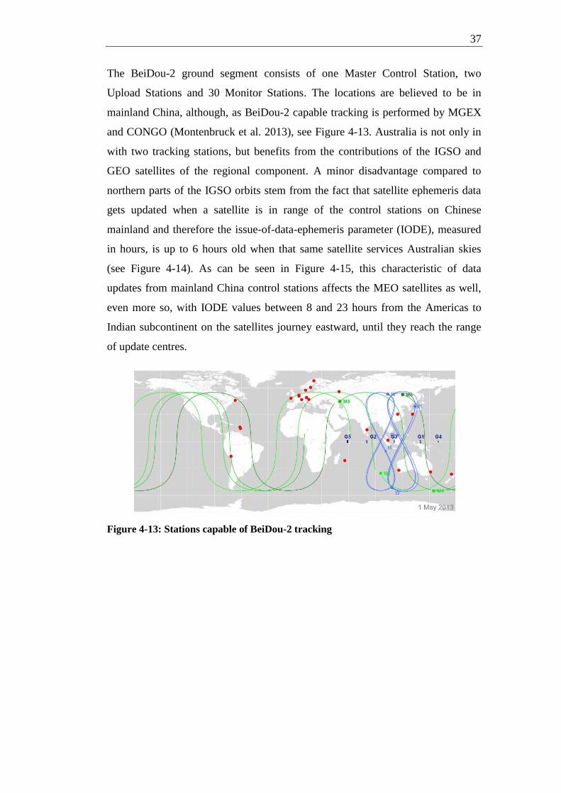
The GLONASS system has all its ground control stations in Russian mainland,
see Figure 4-9, although the differential service aligned with GLONASS, System
of Differential Correction and Monitoring (SDCM) has monitoring stations in
neighbouring, ex USSR countries, Ukraine and Kazakhstan as well as planned
reference stations all around the globe, one of which is in Sydney, see Figure 4-10
and Figure 4-11.
35
Figure 4-8: GPS control segment (NCO 2013)
The Galileo ground segment consists of two Galileo Control Centres (GCCs),
located at Fucino (Italy) and Oberpfaffenhofen (Germany) five telemetry, tracking
and control stations, 10 uplink stations (ULSs), and up to 40 Galileo Sensor
Stations (GSSs). The ULSs transmit navigation signals to the satellites and the
GSSs receive the navigation signal from the constellation for transmission to the
GCCs (Telespazio 2010). The coverage is worldwide with Noumea the nearest
location to Australia, see Figure 4-12.
Figure 4-9: GLONASS ground segment (ESA 2013)

36
Figure 4-10: SDCM reference stations in Russia (Stupak 2012)
Figure 4-11: SDCM reference stations global (Stupak 2012)
Figure 4-12: Galileo Ground Segment (Telespazio 2010)
37
The BeiDou-2 ground segment consists of one Master Control Station, two
Upload Stations and 30 Monitor Stations. The locations are believed to be in
mainland China, although, as BeiDou-2 capable tracking is performed by MGEX
and CONGO (Montenbruck et al. 2013), see Figure 4-13. Australia is not only in
with two tracking stations, but benefits from the contributions of the IGSO and
GEO satellites of the regional component. A minor disadvantage compared to
northern parts of the IGSO orbits stem from the fact that satellite ephemeris data
gets updated when a satellite is in range of the control stations on Chinese
mainland and therefore the issue-of-data-ephemeris parameter (IODE), measured
in hours, is up to 6 hours old when that same satellite services Australian skies
(see Figure 4-14). As can be seen in Figure 4-15, this characteristic of data
updates from mainland China control stations affects the MEO satellites as well,
even more so, with IODE values between 8 and 23 hours from the Americas to
Indian subcontinent on the satellites journey eastward, until they reach the range
of update centres.
Figure 4-13: Stations capable of BeiDou-2 tracking

38
Figure 4-14: BeiDou-2 IGSO SV's ephemeris data age in hours (Montenbruck &
Steigenberger 2013)
Figure 4-15: BeiDou-2 MEO SV's ephemeris data age in hours (Montenbruck & Steigenberger 2013)
4.3 Evaluation of application aspects
4.3.1 Available services
The basic function of a GNSS system is to provide navigation data to the GNSS
user via a receiver. This is done via the navigation signal within the broadcast
signal from the GNSS Space Vehicle.
The GPS system transmits its navigation message in two codes, the
Coarse/Acquisition (C/A) providing Standard Positioning Service (SPS) and the
encrypted Precise-code (P) providing Precise Positioning Service (PPS). The
Precise-code on L2-band has only encrypted navigation message for military use

39
making it P(Y) and cannot be used on its own in a dual frequency scenario. This
has been overcome by employing semi-codeless tracking techniques, which is not
a feature of the GPS system. Furthermore, a new M-code incorporating the
Selective Denial spoofing technique of the C/A-code is included (Ristić et al.
2010).
Glonass also has Standard Precision Service (SP) and High Precision Service
(HP) with C/A and P-codes respectively. Each service is included on both L1 and
L2 bands allowing dual frequency receiver civilian use (Ristić et al. 2010). The
P-code navigation message has never been published but instead was distributed
to the scientific community making the P-code fully available. This was
apparently done to reserve the right to change code at will at any time ESA 2011).
The Galileo runs five different services:
Galileo Open Service (OS), open, free service with guaranteed accuracy
but no quality or integrity information (ESA 2011).
Galileo Commercial Service (CS), adds two encrypted and customer
configurable signals to allow external service integration to CS (ESA
2011).
Galileo Public Regulated Service (PRS) is an Access-Controlled service
intended for law enforcement and government authorities of European
Union offering improved continuity of service in the presence of
interfering threats (ESA 2011).
Galileo Safety of Life (SoL) contains signal integrity information at global
level as opposed to other systems using SBAS to provide for integrity
Galileo Search and Rescue Service (SAR/Galileo) provides SAR service
via detection of Emergency Position Indicating Radio Beacons (EPIRBs)
as well as via a return link from the SAR operator to the distress emitting
beacon (ESA 2011).
BeiDou-2 supports both global worldwide services and regional services. Under
the global services it offers Open Service similar to GPS and Authorized Service
for Military use. Under the regional services users are provided with wide area
differential services including global ionosphere grid data and intersystem time
offsets (Montenbruck & Steigenberger 2013).

40
As a conclusion, and regardless of the common use of external services, The
Galileo is the most attractive proposition for particularly applications where user
has additional services to integrate to the Commercial Service signal. This could
implementation of networks of different technologies combined with GNSS
signals.
BeiDou-2 has both global worldwide services and regional services. Under the
global services it offers Open Service similar to GPS and Authorized Service for
Military use. Under the regional services users are provided with wide area
differential services including ionosphere grid data and intersystem time offsets
(Montenbruck & Steigenberger 2013). The China Satellite Navigation Office has
been slow to publish navigation message content and the BeiDou Navigation
Satellite System Signal In Space Interface Control Document Open Service Signal
B1I (Version 1.0) was published only in late 2012.
4.3.2 Supporting systems
Regional Navigation Satellite Systems (RNSS) use existing GNSS systems and
add to the satellite fleet using GEO satellites targeting regional areas, thus giving
more available satellites and better urban area performance. Figure 4-16 shows
that Australia is well within the operating area of the Japanese Quasi Zenith
Satellite System (QZSS) as well as the Indian IRNSS (Rodríguez 2008). The
QZSS is highly compatible with GPS, whilst the IRNSS seeks to be compatible
with all GNSS systems. In reality it is a matter of receiver technology to be able to
utilise these signals so no advantage or disadvantage can be given to any GNSS.
A Satellite Based Augmentation System (SBAS) is a system that provides
augmentation of any GNSS in a region by using GEO satellites. Another
augmentation system is Ground Based Augmentation System (GBAS). Typically
GBAS could be for flight approach systems to complement other approach system
as in the case of the planned Australian Ground-based Regional Augmentation
System (GRAS) which provides service to the Australian continent (Rodríguez
2008). GBAS transmits augmentation data from ground stations in the same
frequency bands as the GNSS itself.

41
Figure 4-16: QZSS and IRNSS coverage and orbits (Rodríguez 2008).
Figure 4-17 shows the target areas for some SBAS systems as well as GRAS, but
it is worth noting that the Australian user can receive signals from satellites that
service areas far away. Because the augmentation data is optimised for the target
area, the quality of those services is questionable in Australia. Table 4-6 shows
the respective GNSS support of the SBAS systems with GPS clearly most
supported with GLONASS and BeiDou-2 and even Galileo, through Russian
SDCM, also supported. Future plans for SBAS systems stated on their respective
websites did not reveal any changes to the above.
Figure 4-17: Augmentation systems (Rodríguez 2008)

42
Table 4-6: GNSS support in Australia for GNSS (Rodríguez 2008).
SBAS
GP
S
GL
ON
AS
S
Galileo
BeiD
ou
-2
Au
st cov
er
Wide Area Augmentation System (WAAS)
European Geostationary Navigation Overlay Service
(EGNOS) * *
Chinese Satellite Navigation Augmentation System (SNAS)
MTSAT Space-based Augmentation System (MSAS)
System of Differential Correction and Monitoring (SDCM)
GPS and GEO Augmented Navigation system (GAGAN)
Nigerian Communications Satellite System (NIGCOMSAT)
Canadian Wide Area Augmentation System (CWAAS)
South American Satellite Augmentation System (CSTB)
*according to Wikipedia but not EGNOS or others
Global tracking systems are predominantly trying to include all GNSS systems in
their service with an increasing number of stations with receiving capabilities of
GNSS systems other than GPS, which is the dominant GNSS. No differentiators
to be found in that area.
Post-processing services are also clearly moving towards multi-GNSS support but
for the moment GPS is the default system with GLONASS support available with
some but according to Gakstatter (2013) the Australian AUSPOS PPP-service
does not get a mention for support for other than GPS system.
4.3.3 Virtual Reference Station systems
The Virtual Reference Station systems are providing differential positioning
services in real time and in Australia SmartnetAUS has stated: "new Trimble
firmware enables use of @smartnetaus CORS corrections with Glonass enabled
units" (2013). The NSW CORS network is not making a mention of support for
any other GNSS than GPS.

43
4.4 Evaluation of control aspects
"The GLONASS P-code never was published by the system operators,
but it was made known to the scientific community. This means, the
GLONASS P-code is fully available. However, along with the P-code
not being published by the system operators, it neither was officially
released for use outside the Russian Armed Forces. Instead, they
reserve the right to alter the code in future. "(ESA 2011)
This statement is typical description of a GNSS system developed under the
premise of military threats, real or perceived, controlling governmental decision
making.
In short, Galileo is the only GNSS controlled by civilians, the European Union. In
times of conflict the choice of GNSS may come under some regret if the system
shuts down, or more realistically the US employs the M-code to deny GPS signals
from anyone else.
In Australia, individuals make their own choice of GNSS and carry the
consequences in case of service denial and have no real material to use for
evaluating that risk.
Director of Aviation Safety, on behalf of The Australian the Civil Aviation Safety
Authority (CASA), has made an instrument under regulations 174A and 179A of
the Civil Aviation Regulations 1988 (CAR 1988) as Instructions — use of Global
Navigation Satellite System (GNSS) (CASA 2012). It makes a mention of GPS
but not any other GNSS system. Whether this implies an alignment to GPS or not,
or is just pragmatic about the dominance and current availability of GPS is not
clear.
4.5 Conclusions
Each GNSS has strengths and weaknesses, but an effort had to be made to rank
them. Table B-1 in Appendix B, ranks the GNSS systems according to identified
indicators of difference, weighted, perhaps subjectively, by quality and relevance.

44
It seems reasonable to put a heavier weight on features and outcomes that help the
surveyor in his/her work as well as contribute towards making it easier to use
GNSS with higher accuracy in surveying work. History has shown, on the other
hand, that even though technology progresses to resolve issues of accuracy and
ease of use quickly, the foundation of sustainable progress lies in openness and
collaboration. Thus the future is undoubtedly in the path that Galileo is going.

45
Chapter 5 Discussion and Conclusions
5.1 Introduction
This project sought to evaluate the available GNSS systems from an Australian
user's perspective. To get an understanding of the potential factors contributing to
the benefit of one GNSS over another, some literature research was necessary.
This resulted in a vast array of aspects that would need to be processed and
assumptions were made to limit the scope of the project. A sub-research about
what an Australian GNSS user might appreciate most was conducted along the
main task of literature review and related data collection.
An evaluation framework was also needed and the author decided to formulate his
own based on views expressed in literature about GNSS in relation to surveying.
The conclusions are somewhat subjective without empirical data on user
preferences and the matrix of performance credits is limited as in being more a
discussion provoker than absolute ranking method.
5.2 Reviewing assumptions
The Australian user is limited to one GNSS.
o This may be unlikely due to receivers capable of multi-GNSS
operation but conceivable nevertheless.
o Enables relevant comparative assessment.
The Australian user perspective was limited to surveying in Australia.
o Necessary to limit the scope of the project.
All GNSS assessed are fully operational.
o Enables relevant comparative assessment and reflects the likely
scenario in the near future
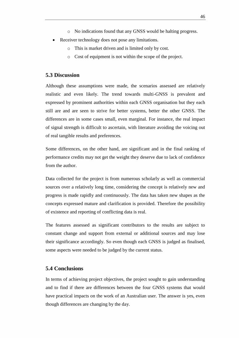
46
o No indications found that any GNSS would be halting progress.
Receiver technology does not pose any limitations.
o This is market driven and is limited only by cost.
o Cost of equipment is not within the scope of the project.
5.3 Discussion
Although these assumptions were made, the scenarios assessed are relatively
realistic and even likely. The trend towards multi-GNSS is prevalent and
expressed by prominent authorities within each GNSS organisation but they each
still are and are seen to strive for better systems, better the other GNSS. The
differences are in some cases small, even marginal. For instance, the real impact
of signal strength is difficult to ascertain, with literature avoiding the voicing out
of real tangible results and preferences.
Some differences, on the other hand, are significant and in the final ranking of
performance credits may not get the weight they deserve due to lack of confidence
from the author.
Data collected for the project is from numerous scholarly as well as commercial
sources over a relatively long time, considering the concept is relatively new and
progress is made rapidly and continuously. The data has taken new shapes as the
concepts expressed mature and clarification is provided. Therefore the possibility
of existence and reporting of conflicting data is real.
The features assessed as significant contributors to the results are subject to
constant change and support from external or additional sources and may lose
their significance accordingly. So even though each GNSS is judged as finalised,
some aspects were needed to be judged by the current status.
5.4 Conclusions
In terms of achieving project objectives, the project sought to gain understanding
and to find if there are differences between the four GNSS systems that would
have practical impacts on the work of an Australian user. The answer is yes, even
though differences are changing by the day.

47
In general, GNSS systems are headed to more compatibility and interoperability.
Superiority and advantages in an area or other are ebbing and flowing from one
system to another but it was rather surprising to realise that the fate of the GNSS
future is in the hand of soldiers with scenarios of threat painted to justify decisions
to keep the crème de la crème in GNSS technology away from public use.
The result of the evaluation is laid out in the matrix in Table B-1 but that is
heavily distorted by the dominance of GPS in the market. More interestingly,
Galileo seems to be hitting the targets in terms of services and applications people
want, BeiDou-2 has promise in particular in our region and GLONASS is
desperately seeking partners in its future plans for augmentation.

48
References:
Avila-Rodriguez, J, Hein, G, Wallner, S, Issler, J, Ries, L, Lestarquit, L, de Latour, A, Godet,
J, Bastide, F, Pratt, T, & Owen, J 2008, 'The MBOC Modulation: The Final Touch to the
Galileo Frequency and Signal Plan', NAVIGATION, vol. 55, no. 1, pp. 14-28.
de Bakker, PF 2007, 'Effects of Radio Frequency Interference on GNSS Receiver Output ',
Masters Thesis, Delft University of Technology Faculty of Aerospace Engineering, Delft
University of Technology, The Netherlands.
Chen, H-C, Huang, Y-S, Chiang, K-W, Yang, M, & Rau, RJ 2009, 'THE PERFORMANCE
COMPARISON BETWEEN GPS AND BeiDou-2/COMPASS: A PERSPECTIVE FROM
ASIA', Journal of the Chinese Institute of Engineers, vol. 32, no. 5, pp. 679-689.
Cojocaru, S 2009, 'GPS-GLONASS-GALILEO: A Dynamical Comparison', The Journal of
Navigation, vol. 62, pp. 135–150, The Royal Institute of Navigation.
Dalporte, J 2009, 'The Definition and Implementation of Galileo System Time (GST)',
Proceedings of ICG-4 WG-D on GNSS time scales, United Nations Office for Outer Space
Affairs.
Dawoud, S, 'GNSS principles and comparison', Potsdam University, Potsdam,
http://www.snet.tu-berlin.de/fileadmin/fg220/courses/WS1112/snet-project/gnss-principles-
and-comparison_dawoud.pdf.
Dempster, AG & Hewitson, S 2007,' The “System of Systems” receiver: An Australian
opportunity?', paper to be presented at IGNSS2007 Symposium on GPS/GNSS, 4-6
December 2007, Sydney, Australia.
Dempster, AG & Rizos, C 2009, 'Implications of a "system of systems" receiver', CD-ROM
proceedings of Surveying & Spatial Sciences Institute Biennial International Conference, 28
September – 2 October 2009, Adelaide, Australia.
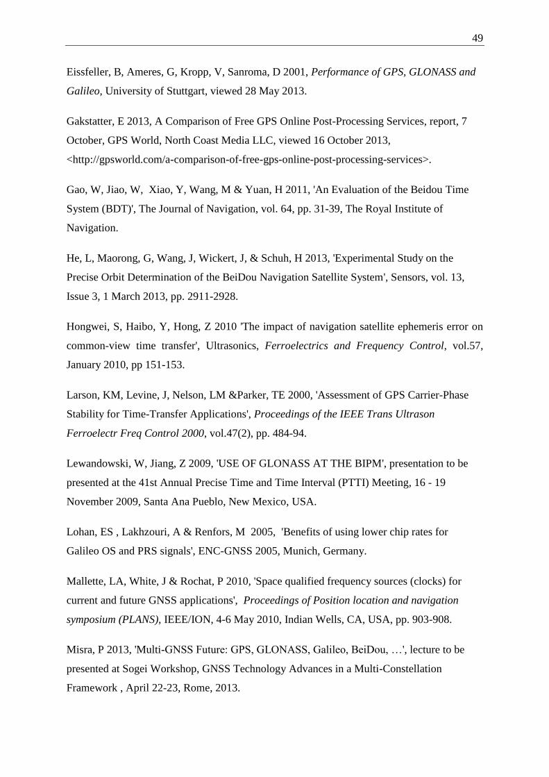
49
Eissfeller, B, Ameres, G, Kropp, V, Sanroma, D 2001, Performance of GPS, GLONASS and
Galileo, University of Stuttgart, viewed 28 May 2013.
Gakstatter, E 2013, A Comparison of Free GPS Online Post-Processing Services, report, 7
October, GPS World, North Coast Media LLC, viewed 16 October 2013,
<http://gpsworld.com/a-comparison-of-free-gps-online-post-processing-services>.
Gao, W, Jiao, W, Xiao, Y, Wang, M & Yuan, H 2011, 'An Evaluation of the Beidou Time
System (BDT)', The Journal of Navigation, vol. 64, pp. 31-39, The Royal Institute of
Navigation.
He, L, Maorong, G, Wang, J, Wickert, J, & Schuh, H 2013, 'Experimental Study on the
Precise Orbit Determination of the BeiDou Navigation Satellite System', Sensors, vol. 13,
Issue 3, 1 March 2013, pp. 2911-2928.
Hongwei, S, Haibo, Y, Hong, Z 2010 'The impact of navigation satellite ephemeris error on
common-view time transfer', Ultrasonics, Ferroelectrics and Frequency Control, vol.57,
January 2010, pp 151-153.
Larson, KM, Levine, J, Nelson, LM &Parker, TE 2000, 'Assessment of GPS Carrier-Phase
Stability for Time-Transfer Applications', Proceedings of the IEEE Trans Ultrason
Ferroelectr Freq Control 2000, vol.47(2), pp. 484-94.
Lewandowski, W, Jiang, Z 2009, 'USE OF GLONASS AT THE BIPM', presentation to be
presented at the 41st Annual Precise Time and Time Interval (PTTI) Meeting, 16 - 19
November 2009, Santa Ana Pueblo, New Mexico, USA.
Lohan, ES , Lakhzouri, A & Renfors, M 2005, 'Benefits of using lower chip rates for
Galileo OS and PRS signals', ENC-GNSS 2005, Munich, Germany.
Mallette, LA, White, J & Rochat, P 2010, 'Space qualified frequency sources (clocks) for
current and future GNSS applications', Proceedings of Position location and navigation
symposium (PLANS), IEEE/ION, 4-6 May 2010, Indian Wells, CA, USA, pp. 903-908.
Misra, P 2013, 'Multi-GNSS Future: GPS, GLONASS, Galileo, BeiDou, …', lecture to be
presented at Sogei Workshop, GNSS Technology Advances in a Multi-Constellation
Framework , April 22-23, Rome, 2013.

50
Montenbruck, O & Steigenberger, P 2013, 'The BeiDou Navigation Message' paper to be
presented at International Global Navigation Satellite Systems Society IGNSS Symposium,
16-18 July 2013, Gold Coast, Qld, Australia.
Montenbruck, O, Steigenberger, P, Hauschild, A 2013, 'From China with Love – The BeiDou
Navigation System ', presentation to be presented at the Satellite Navigation Seminar, 14 May
2013, Munich, Germany.
Montenbruck, O, Hauschild, A, Steigenberger, P, Hugentobler, U, Teunissen, P &
Nakamura, S 2012, 'Initial assessment of the COMPASS/BeiDou-2 regional navigation
satellite system', published online, Springer.
Pellerin, C 2006, United States Updates Global Positioning System Technology, media
release, 03 February 2006, U.S. Department of State, viewed 28 May 2013,
<http://www.america.gov/st/washfile-english/2006/February/20060203125928lcnirellep0.5061
609.html>.
Ristić, A, Govedarica, M, Petrovački, D 2010, 'GNSS – Status and Perspective', Journal on
Processing and Energy in Agriculture, vol. 14, 2010, pp. 6-10.
Rizos, C, Higgins, M, Hewitson, S 2005, 'New GNSS Developments and their Impact on
Survey Service Providers and Surveyors', paper to be presented at SSC2005 Spatial
Intelligence, Innovation and Praxis: The national biennial Conference of the Spatial Sciences
Institute, September 2005, Melbourne.
Rodríguez, J 2008, 'On Generalized Signal Waveforms for Satellite Navigation', Doctoral
Thesis, FAF University of Munich, Munich.
—— 2011, GALILEO Signal Plan, European Space Agency Navipedia, viewed 8 September
2013, <http://www.navipedia.net/index.php/GALILEO_Signal_Plan>.
Roberts, C 2011, 'How will all the new GNSS signals help RTK surveyors?', Proceedings of
the SPATIAL SCIENCES & SURVEYING BIENNIAL CONFERENCE 2011, 21-25 November
2011, Wellington, New Zealand, pp. 40-51.
Steudler, D & Kaufmann, J 2002, Benchmarking Cadastral System, International Federeation
of Surveyors FIG, Denmark.

51
Stupak, G 2010, 'GLONASS status and development plans', presentation to be presented at
the 5th Meeting of the International Committee on GNSS, presentation, Turin, Italy, 18 – 22
October 2010.
—— 2012, 'SDCM status and plans', presentation to be presented at the Seventh Meeting of
the International Committee on Global Navigation Satellite Systems, 4 – 9 November 2012,
Beijing, China.
Tegedor, J, Melgard, T, Øvstedal, O & Vigen, E 2013, 'Multi-constellation Precise Point
Positioning including GPS, Glonass, Galileo and BeiDou', presentation to be presented at
GNSS Precise Point Positioning Workshop: Reaching Full Potential, 12-14 June 2013,
Ottawa, Canada.
Werner, W & Winkel, J 2003, 'TCAR and MCAR Options With Galileo and GPS',
Proceedings of 16th Tech. Meeting of the Satellite Div. of the U.S. Institute of Navigation,
Portland, Oregon, 9-11 September 2003, pp.790-800.
Yates, G 2013, Grant Yates: twitter feed, viewed 16 October 2013,
<https://twitter.com/smartnetaus>.
CASA 356/12 - Instructions - use of Global Navigation Satellite System (GNSS) -
F2012L02141, (instrument under regulations 174A and 179A of the Civil Aviation
Regulations 1988) 2012 (Director of Aviation Safety, on behalf of CASA).
Control Segment 2013, National Coordination Office (NCO) for Space-Based Positioning,
Navigation, and Timing, Washington, D.C. USA, viewed 17 October 2013,
<http://www.gps.gov/systems/gps/control/>.
COoperative Network for GIOVE Observations (CONGO) 2013, Technische Universität
München, Munich, Germany, viewed 17 October 2013, <http://www.iapg.bv.tum.de/190749-
bD1lbg-~iapg~forschung~gnss~congo.html>.
DGNSS Services 2012, OmniSTAR brochure, OmniSTAR, Leidschendam, The Netherlands,
viewed 16 October 2013,
<http://www.omnistar.com/Portals/0/downloads/brochures/DGNSS%20Service%20UK%20
A4-spread%20(3-5-2012)%20Web.pdf>.

52
GALILEO CONTROL CENTRE 2012, Telespazio brochure, Telespazio, Rome, Italy, viewed
17October 2013, <http://www.telespazio.com/docs/brodoc/GCC_eng.pdf>.
Galileo Terrestrial Reference Frame 2012, ESA, Prague, Czech Republic, viewed 28 May
2013, <http://www.oosa.unvienna.org/pdf/icg/2012/template/GTRF.pdf>.
GLONASS Ground Segment 2012, ESA, Czech Republic, viewed 17 October 2013,
<http://www.navipedia.net/index.php/GLONASS_Ground_Segment>.
How the Galileo atomic clocks work 2012, ESA, Czech Republic, viewed 28 May 2013,
<http://www.esa.int/Our_Activities/Navigation/How_the_Galileo_atomic_clocks_work>.
SBAS Made Easy 2013, GENEQ Inc, Montréal, Canada, viewed 16 October 2013,
<http://sxbluegps.com/technology/sbas-made-easy/>.
A-1
Chapter 6 Appendix A
Appendix A
Project Specification
A-2

B-1
Chapter 7 Appendix B
Appendix B
Performance credit ranking

B-2
Table B-1: Performance credit ranking
Legend False Significant True Confident Inconclusive
GPS GLONASS Galileo BeiDou-2
Evaluation area Identified Indicators Desired status Performance
Credit
Data Quality Performance
Credit
Data Quality Performance
Credit
Data Quality Performance
Credit
Data Quality
Physical aspect Frequency bands Multiple bands support TCAR and MCAR
Receiver design friendly
Multipath mitigation
Signal structure Receiver design friendly
Multipath mitigation characteristic
Tracking ability
Signal strengths Strong signal helps in challenging environments Strong signal improves fix time
Availability Maximum usable satellites
Orbital differences Inclination angle to support all of target area
Geographical differences Designed to support target area
Evaluation area Identified Indicators Desired status
Application aspect Available services Services available additional to navigation
Integration with other technologies
Quality of service message
Differential service
Ionospheric correction delivery
Supporting systems SBAS support
Global tracking service support
Virtual Reference Station systems
Supported platform for VRS (CORS)
Evaluation area Identified Indicators Desired status
Control aspect Reliability of access Access not conditional
Guaranteed service Service guaranteed
Overall suitable