Evaluation of Stress Corrosion Cracking Damage to an API ...Stress Corrosion Cracking, Residual...
13
Materials Sciences and Applications, 2016, 7, 610-622 http://www.scirp.org/journal/msa ISSN Online: 2153-1188 ISSN Print: 2153-117X DOI: 10.4236/msa.2016.710050 October 12, 2016 Evaluation of Stress Corrosion Cracking Damage to an API 5L X52 Pipeline Transporting Ammonia: A Case Study José Luis Mora-Mendoza 1 , Mónica Jazmín Hernández-Gayosso 2 , Daniel Antonio Morales-Serrat 1 , Octaviano Roque-Oms 1 , Digna Alejandra Del Angel 1 , Gerardo Zavala-Olivares 2 1 Petróleos Mexicanos, Marina Nacional 329, Col. Petróleos Mexicanos, CDMX, Ciudad de México, México 2 Instituto Mexicano del Petróleo, Eje Central Lázaro Cárdenas Norte 152, Col. San Bartolo Atepehuacan, CDMX, Ciudad de México, México Abstract The high number of leak events that took place in recent years at a 25.4 cm (10”) Ø pipeline transporting anhydrous liquid ammonia, located in the Southeast of Mexico, was the main reason to carry out a number of field studies and laboratory tests that helped establish not only the failure causes but also mitigation and control solutions. The performed activities included direct evaluation at failure sites, total repair pro- grams, metallographic studies and pipeline flexibility analyses. The obtained results were useful to conclude that the failures obeyed a cracking mechanism by Stress Corrosion Cracking (SCC) which was caused by the combined effect of different fac- tors: high stress resistance, high hardness of the base metal with a microstructure prone to brittleness and residual strains originated during the pipeline construction. From the operative, logistic and financial standpoints, it is not feasible to release the stress of approximately 22 km of pipeline. Therefore, the only viable solution is to install a new pipeline with suitable fabrication, construction and installation specifi- cations aimed at preventing the SCC phenomenon. Keywords Stress Corrosion Cracking, Residual Stress, Ammonia Transporting Pipeline 1. Introduction It is well known that the Stress Corrosion Cracking (SCC) mechanism is caused by the combination of tensile stress and a corrosive medium [1]. Generally, SCC provokes cracks and fractures with a sudden structure rupture [2]-[4]. How to cite this paper: Mora-Mendoza, J.L., Hernández-Gayosso, M.J., Morales- Serrat, D.A., Roque-Oms, O., Del Angel, D.A. and Zavala-Olivares, G. (2016) Evalua- tion of Stress Corrosion Cracking Damage to an API 5L X52 Pipeline Transporting Ammonia: A Case Study. Materials Sciences and Applications, 7, 610-622. http://dx.doi.org/10.4236/msa.2016.710050 Received: September 10, 2016 Accepted: October 9, 2016 Published: October 12, 2016 Copyright © 2016 by authors and Scientific Research Publishing Inc. This work is licensed under the Creative Commons Attribution International License (CC BY 4.0). http://creativecommons.org/licenses/by/4.0/ Open Access
Transcript of Evaluation of Stress Corrosion Cracking Damage to an API ...Stress Corrosion Cracking, Residual...

Materials Sciences and Applications 2016 7 610-622 httpwwwscirporgjournalmsa
ISSN Online 2153-1188 ISSN Print 2153-117X
DOI 104236msa2016710050 October 12 2016
Evaluation of Stress Corrosion Cracking Damage to an API 5L X52 Pipeline Transporting Ammonia A Case Study
Joseacute Luis Mora-Mendoza1 Moacutenica Jazmiacuten Hernaacutendez-Gayosso2 Daniel Antonio Morales-Serrat1 Octaviano Roque-Oms1 Digna Alejandra Del Angel1 Gerardo Zavala-Olivares2
1Petroacuteleos Mexicanos Marina Nacional 329 Col Petroacuteleos Mexicanos CDMX Ciudad de Meacutexico Meacutexico 2Instituto Mexicano del Petroacuteleo Eje Central Laacutezaro Caacuterdenas Norte 152 Col San Bartolo Atepehuacan CDMX Ciudad de Meacutexico Meacutexico
Abstract The high number of leak events that took place in recent years at a 254 cm (10rdquo) Oslash pipeline transporting anhydrous liquid ammonia located in the Southeast of Mexico was the main reason to carry out a number of field studies and laboratory tests that helped establish not only the failure causes but also mitigation and control solutions The performed activities included direct evaluation at failure sites total repair pro-grams metallographic studies and pipeline flexibility analyses The obtained results were useful to conclude that the failures obeyed a cracking mechanism by Stress Corrosion Cracking (SCC) which was caused by the combined effect of different fac-tors high stress resistance high hardness of the base metal with a microstructure prone to brittleness and residual strains originated during the pipeline construction From the operative logistic and financial standpoints it is not feasible to release the stress of approximately 22 km of pipeline Therefore the only viable solution is to install a new pipeline with suitable fabrication construction and installation specifi-cations aimed at preventing the SCC phenomenon
Keywords Stress Corrosion Cracking Residual Stress Ammonia Transporting Pipeline
1 Introduction
It is well known that the Stress Corrosion Cracking (SCC) mechanism is caused by the combination of tensile stress and a corrosive medium [1] Generally SCC provokes cracks and fractures with a sudden structure rupture [2]-[4]
How to cite this paper Mora-Mendoza JL Hernaacutendez-Gayosso MJ Morales- Serrat DA Roque-Oms O Del Angel DA and Zavala-Olivares G (2016) Evalua-tion of Stress Corrosion Cracking Damage to an API 5L X52 Pipeline Transporting Ammonia A Case Study Materials Sciences and Applications 7 610-622 httpdxdoiorg104236msa2016710050 Received September 10 2016 Accepted October 9 2016 Published October 12 2016 Copyright copy 2016 by authors and Scientific Research Publishing Inc This work is licensed under the Creative Commons Attribution International License (CC BY 40) httpcreativecommonsorglicensesby40
Open Access
J L Mora-Mendoza et al
611
Tensile stress can stem from either stress applied directly on a structure or residual stress originated during the production andor construction processes Examples of processes that trigger residual stress are cold working processes [5] welding thermal treatments and machining
In general during the SSC mechanism most part of the structure surface is not at-tacked by corrosion and frequently thin cracks appear penetrating the material through intergranular or transgranular forms [6] Macroscopically speaking the SSC fractures feature a fragile appearance [7]-[8]
SCC has been classified as a catastrophic type of corrosion where it is difficult to detect fine cracks and the damage is not easily predictable A disastrous failure can oc-cur all of a sudden with a minimum loss of total material [9]
In the past SSC was considered as a problem coming from some alloys in specific environments However currently it is known that SCC has occurred in a wide variety of alloy systems in different environments [10]-[12]
Low alloy steel types are less susceptible to SCC than high alloy steels although these materials are exposed to SCC in water containing chloride ions [2] Likewise low hardness steels provide apparently a higher resistance degree to SCC than high resis-tance steels [13]
The most effective ways to prevent SCC from happening are the use of suitable ma-terials reduction or elimination of stress sources and removal of critical species from the medium Some SCC control methods include the stress relief by means of a thermal treatment after the welding process protecting coatings and corrosion inhibitors among others [3] [14]
On the other hand several important events have been reported at pipelines trans-porting anhydrous liquid ammonia [15] Most of these events occurred in the USA which is a country where the highest number of pipelines transporting anhydrous liq-uid ammonia is located In nine important events it was reported that the causes had been overpressure (1) external corrosion (2) maintenance problems (1) fatigue cra- cking (1) weld failure (1) unexpected failure during the freezing-melting cycle (1) and vandalism (2)
Likewise it is known [13] that liquid ammonia can cause SCC in carbon steels in the presence of oxygen although it has been established that high stress levels are required to start the cracking process The residual strains in welds of materials with high and intermediate hardness or welds with high hardness accompanied by residual strains can be enough to trigger SCC when oxygen is present at the right concentration for this process to take place
In this work a case study originated by the high frequency of leak events taking place at a 254 cm (10rdquo) Oslash pipeline transporting anhydrous liquid ammonia is presented
Several field and laboratory analyses were carried out in order to establish the causes for the leaks in the pipeline The SCC is considered as the main metal failure process The sources for this kind of mechanism were determined and the applicable solutions for the problem were given
J L Mora-Mendoza et al
612
2 Background
The studied pipeline is made from API 5L X52 steel with no longitudinal seam it has an approximate length of 46 Km with diameter of 254 cm (10 inches) and a nominal wall thickness of 09271 cm (0365 inches) The pipeline transports anhydrous liquid ammonia at an operation pressure of 28 kgcmminus2 and an output temperature between minus5 and 0˚C The maximum historical operation pressure at the pipeline has been 40 kgcmminus2
The statistics of events at the pipeline reports 20 leaks for a period of 13 operation years from which 17 occurred in three consecutive years as shown in Table 1
In most failure points circumferential fractures were identified which were close to the field welds and generally located at 12 technical hours from the pipeline (Figure 1) In general these types of circumferential fractures tend to be favored in their formation and propagation by axial stress and pipeline flexion In five leaks it was not possible to identify the type of damage caused to the pipeline due to the priority assigned to repair and eliminate the leak to reestablish the product transportation
Table 1 Statistics of ammonia leaks
Years of operation of the pipeline transport system Ammonia leaks
2 2
7 1
11 5
12 6
13 6
Total 20
Figure 1 Ammonia leak located close to a circumferential weld at 12 technical hours from the pipeline
J L Mora-Mendoza et al
613
3 Initial Field and Laboratory Studies
After two years of its construction a number of field and laboratory activities were car-ried out to establish the failure causes of the two first leaks that occurred at the pipeline reporting the following findings
1) During the direct evaluation at 17 sites there were pipeline segments with dis-placements between the original plane and the cut section of more than 90 cm which recovered their linearity after removing them from the ditches (Figure 2)
2) The laboratory results reported cracks in the analyzed segments which were asso-ciated to the stress corrosion cracking (SCC) mechanism The origin of the strains was attributed to the inadequate field conformation of the pipeline by forcing the pipes to adjust to the terrain topographic profile
31 Metallographic Analyses
Because of the high occurrence of leaks at the pipeline after 12 and 13 operation years metallographic analyses were carried out [16]-[19] It was established that the stress re-sistance of the base metal was considerably higher than the one specified for API 5 L X52 steel [20] (Table 2) The base metal showed high hardness which is characteristic of a brittle microstructure [21] [22] (Table 3)
(a) (b)
Figure 2 (a) Curved pipeline (b) Withdrawn section with linearity reco- very
Table 2 Yield and tensile strengths [20]
Sample or specification Yield strength Kgcmminus2 (PSI) Tensile strength Kgcmminus2 (PSI)
A 4935 (70500 PSI) 6874 (98200 PSI)
API 5L X65 4550 (minimum) (65000 PSI) 5390 (minimum) (77000 PSI)
API 5L X70 4900 (minimum) (70000 PSI) 5740 (minimum) (82000 PSI)
J L Mora-Mendoza et al
614
The microstructure of the base metal showed abnormal carbon segregation and pear-lite acicular morphology characteristic of a fragile microstructure [16] (Figure 3) The presence of fractures with fragile aspect and multiple cracking was also identified Nei-ther metal loss nor pitting corrosion occurred (Figure 4) The cracks being of the transgranular type displayed trajectories going from the interior to the exterior part of the pipeline wall (Figure 5)
Based on the results of these metallographic analyses it was concluded that the fail-ures obeyed to a stress corrosion cracking (SCC) mechanism which was originated by various factors high stress resistance high hardness a brittleness-susceptible micro-structure and the presence of residual stress that was probably originated from the pipeline construction and lying
Here the three conditions required for the occurrence of SCC were achieved bull A susceptible material bull An environment that causes SCC for that material bull Sufficient tensile stress to induce SCC
This situation was observed by means of the analyses performed to the base metal
Table 3 Brinell hardness
3 Average Brinell hardness (HB)
A 94
Figure 3 Base metal microstructure
Figure 4 Brittle fracture
J L Mora-Mendoza et al
615
where it was possible to observe the changes originated during the tube construction and the strains caused by the criterion considered for the pipeline lying
32 Total Repair Actions
Due to the constant failures that occurred between the 12th and 13th years of service the ldquosplit sleeverdquo repairs used to stop the leaks were replaced by new pipelines sections (reels) During these works the presence of residual stress induced during the pipeline construction was confirmed The most remarkable results of these works were
1) At the 3 + 300 kilometer once the pipeline cut was finished a linear displacement of approximately 4 cm was observed (Figure 6) which made necessary further digging in order to match correctly the pipe and release the present stress
2) At the 8 + 025 kilometer the pipeline cut was finished and a linear displacement of approximately 5 cm was also observed as shown in Figure 7 It was necessary to continue digging to match correctly the pipe and release the present stress
3) At the 15 + 137 kilometer which is close to a sectional valve a pipe vertical dis-placement of approximately 4 cm was observed when the valve flange was unscrewed Figure 8 In order to perform the total repair it was necessary to modify the valve supports to match the flanges and release the present stress
Figure 5 Microscopy fractography analysis and transgranular cracks
Figure 6 Pipeline cut at the 3 + 300 kilometer
J L Mora-Mendoza et al
616
Figure 7 Pipeline cut at the 8 + 025 kilometer
Figure 8 Pipeline vertical displacement at the sectional valve
33 Pipeline Flexibility
By considering the pipeline loads and operative conditions along with the topographic profile of the terrain reported by the GPS of the last ILI inspection [23] a pipeline flex-ibility analysis was performed to identify the zones or sites with higher stress levels andor displacement probability The results showed (Figure 9 and Figure 10) that the pipeline is submitted to stress conditions that donrsquot surpasses 35 of the allowed limits established by ASME B314 2009 [24] There are displacement points and relatively high stress levels (peaks) in the zones where failures occurred in the pipeline The highest displacements and stress levels were located at two sectional valves (15 + 161 and 30 + 034 kilometers) In addition there is a region with stress fluctuations that are in accordance with the highest occurrence of pipeline failures
34 Direct Inspection
By considering the high stress and displacement levels strain variations from the flex-ibility analysis leaks record and stress induced during pipeline construction 13 sites
J L Mora-Mendoza et al
617
were selected to carry out a field direct evaluation using ultrasonic technology with industrial phase arrangement for the detection of possible cracks along with other non-destructive field techniques [25]
The direct evaluation results showed the presence of cracks at the 3 + 371 and 15 + 161 kilometers (Table 4 and Table 5) and microstructures with fragile aspect andor high hardness at different sites
Figure 9 Pipeline stress profile
Figure 10 Pipeline displacement profile
J L Mora-Mendoza et al
618
35 Evaluation of the Ammonia Pipeline
The probability of cracking throughout the pipeline was established by analyzing and putting together the evidence of the pipeline historical records and those obtained from recent works and field andor laboratory studies considering in general eight factors or aspects and relative scores (Table 6) Table 4 Results of the direct evaluation at the 3 + 371 kilometer
Type Crack confined inside the pipe body
Location 12 technical hours from the pipe at 40 mm of field weld
Dimensions 1143 mm of circumferential length and 0077rdquo of radial length Figure 11
Evaluation Crack mechanics Crack located at the ldquono failure zonerdquo The failure stress is 47 of the applied stress
Recomendation Repair with a type B sleeve designed to contain the pipeline operation pressure in the case of a leak or the possible replacement of the pipe
Performed action Pipe replacement
Table 5 Results of the direct evaluation at the 15 + 161 kilometer
Type Crack confined inside the pipe body
Location 12 technical hours from the pipe at 16 mm of field weldand at 0220rdquo of the external pipe surface
Dimensions 2336 mm of circumferential length and 0143rdquo of radial length Figure 12
Evaluation Crack mechanics Crack located at the ldquono failure zonerdquo The failure stress is 74 of the applied stress
Recomendation Pipe replacement
Performed action Pipe replacement
Figure 11 Dimensioning and location of a crack at the 3 + 371 km
0371
0034
40 mm
01110371
0034
40 mm
01110371
0034
40 mm
0111
J L Mora-Mendoza et al
619
Figure 12 Location of the crack at the 15 + 161 km
Table 6 Factors aspects for cracking probability analysis
No FactorAspect Reference Cracking Probability Score
1 Leaks Historical records Very high failure probability 100
2 High hardness in the
base material (susceptible material)
Metallographic analyses laboratoryfield
High failure probability if stress levels are increased
80
3 By force withdrawn
installed sections (high stress levels)
Field works High failure probability 80
4 Linearity recovery of
withdrawn pipe sections (high stress levels)
Field works Very high failure probability 100
5 Identified cracks Metallographic analyses
laboratoryfield High failure probability 100
6 High stress level sites Flexibility analysis Intermediate failure
probability if combined with susceptible materials
50
7 Sites with high displacement
Flexibility analysis Intermediate failure
probability if combined with susceptible materials
50
8 Sites with varying
stress level Flexibility analysis
High failure probability if combined
with susceptible materials 80
In order to establish the cracking probability in the pipeline intervals indicated in
Table 7 were considered which are based on the addition of the scores of the consi-dered factors or aspects
The results show that approximately 50 of the pipeline length has high or very high probability of cracking failure (from 0 + 000 to 22 + 036 kilometers) and that the most critical segments are located from 0 + 000 to 7 + 900 Km and from 15 + 161 to 15 + 291 km (Table 8)
Circumferentialseal
0220
16mm
t= 0363
Crack
Circumferentialseal
0220
16mm
t= 0363
Crack
Circumferentialseal
0220
16mm
t= 0363
Crack
Circumferentialseal
0220
16mm
t= 0363
Crack
J L Mora-Mendoza et al
620
Table 7 Cracking probability score intervales
Cracking probability Score intervals
Very high ge400
High 200 to 399
Intermediate lt200
Table 8 Cracking probability
Length (km) Factors
Cracking probability 1 2 3 4 5 6 7 8
0 + 000 ndash 7 + 900 Very high
8 + 070 ndash 10 + 105 - - - - High
15 + 161 ndash 15 + 291 - - - Very high
16 + 912 ndash 22 + 036 - - - - High
22 + 515 ndash 29 + 319 - - - - - - Intermediate
30 + 034 ndash 30 + 349 - - - - - - Intermediate
32 + 522 ndash 45 + 494 - - - - - - Intermediate
As a considerable pipeline length shows high probability of cracking failure (22 ki-
lometers) the first option would be to carry out field actions to eliminate andor release the stress to which the pipeline is submitted
Already tested releasing stress for this type of situations are excavations of several ki-lometers to uncover the pipeline in order to it be elastically displaced (cold ldquobouncingrdquo or ldquospring backrdquo) carrying out specific cuts and ldquono-forcedrdquo joints with transition reels
From the operative logistic and financial standpoints the already mentioned option is considered as unviable and it is only recommendable to perform the necessary ac-tions to construct a new pipeline with suitable fabrication construction and installation specifications aimed at preventing the SCC phenomenon from happening
4 Conclusions
The field and laboratory studies confirmed that the origin of the leaks at the ammonia pipeline studied in the present work obeyed to a Stress Cracking Corrosion (SCC) me-chanism of brittle type which was the result of the interaction among a fragile material an intermediate corrosive medium and high residual stress levels originated from the pipeline construction
The steel used to produce the pipes is more susceptible than normal to stress crack-ing due to the fact that it exhibits high hardness high stress resistance and a brittle mi-crostructure
The analyses of failure probability considering the pipeline historical documental records and the recent works along with field andor laboratory studies indicate that approximately 50 of the pipeline length shows high or very high probability of crack-ing failure
J L Mora-Mendoza et al
621
From the operative logistic and financial points of view it is not feasible to release the stress of approximately 22 km of pipeline and only the construction of a new pipe-line with suitable fabrication construction and installation specifications aimed at pre-venting the SCC phenomenon from happening is viable
The SCC mechanism is well identified for these types of systems and its development is expected Therefore it is necessary to consider the following recommendations in order to decrease the SCC probability bull To consider studies and kinematic registers of the ground where the pipeline is lying
in order to determine the mass movements or batter bull To minimize the residual stresses originated in the base metal during construction
considering also a heat treatment for stresses relief when welding is applied bull To monitor through nondestructive techniques and tests the occurrence of failure
susceptible zones considering factors such as hardness increase metal strains and stresses rise along with the type of fluid transported by the pipeline
bull To identify critical areas such as welding pipeline deviations hits or pipeline fail-ures during lying in order to follow their behavior against conditions to which the pipeline is subjected
References [1] Popov BN (2015) Stress Corrosion Cracking In Corrosion Engineering Principles and
Solved Problems Capiacutetulo 9 365-450 httpdxdoiorg101016b978-0-444-62722-300009-4
[2] Cheng YF (2013) Stress Corrosion Cracking of Pipelines John Wiley amp Sons 288 p
[3] Heidersbach R (2011) Metallurgy and Corrosion Control in Oil and Gas Production 296 p httpdxdoiorg1010029780470925782
[4] Jones RH (1992) Stress-Corrosion Cracking ASM International 445 p
[5] Mahajanam Sudhakar PV Mcintyre Dale R and Hovey Lawrence K (2009) Residual Stress Control to Prevent Environment Cracking of Stainless Steels Materials Performance 48 60-64
[6] Carcea AG and Newman RC (2010) Mechanistic Studies of Stress Corrosion Cracking of Carbon Steel in Alcoholic Solutions 218th ECS Meeting The Electrochemical Society 1245
[7] Antunes PD Correa EO Barbosa RP Silva EM Padilha AF and Guimaraes PM (2013) Effect of Weld Metal Chemistry on Stress Corrosion Cracking Behavior of AISI 444 Ferritic Stainless Steel Weldments in Boiling Chloride Solution Materials and Corrosion 64 415-421 httpdxdoiorg101002maco201106186
[8] Lu BT Chen ZK Luo JL Patchett BM and Xu ZH (2005) Pitting and Stress Corro-sion Cracking Behavior in Welded Austenitic Stainless Steel Electrochimica Acta 50 1391- 1403 httpdxdoiorg101016jelectacta200408036
[9] Balraj V and Paul R (2009) Evaluation of Weld Root Corrosion of Type 316L Stainless Steel Materials Performance 48 80-82
[10] Ramesh S (2009) Ethanol Corrosion in Pipelines Materials Performance 48 53-55
[11] Janikowski Daniel S (2008) Selecting Tubing Materials for Power Generation Heat Ex-changers Materials Performance 47 58-63
J L Mora-Mendoza et al
622
[12] Linton VM and Laycock NJ (2008) Stress Corrosion Cracking of a Vinyl Chloride Stripper Vessel Materials Performance 47 74-79
[13] Loginow AW (1989) Stress Corrosion Cracking of Steel in Liquefied Ammonia Servicemdash A Recapitulation National Board Classic Series National Board Bulletin
[14] Cottis RA (2000) Stress Corrosion CrackingmdashGuides to Good Practice in Corrosion Control The National Physical Laboratory 1-16 wwwnplcouk
[15] Guidance for Inspection of and Leak Detection in Liquid Ammonia Pipelines 2008 Edition Issue 2013 Fertilizer Europe
[16] ASTM E3-11 Standard Guide for Preparation of Metallographic Specimens
[17] ASTM E340-15 Standard Practice for Macroetching Metals and Alloys
[18] ASTM E407-07 (2015) Standard Practice for Microetching Metals and Alloys
[19] ASTM E112-13 Standard Test Methods for Determining Average Grain Size
[20] ASTM E8E8M-15a Standard Test Methods for Tension Testing of Metallic Materials
[21] ASTM E10-15a Standard Test Method for Brinell Hardness of Metallic Materials
[22] ASTM E140-12b Standard Hardness Conversion Tables for Metals Relationship among Brinell Hardness Vickers Hardness Rockwell Hardness Superficial Hardness Noop Hard- ness Scleroscope Hardness and Leeb Hardness
[23] NACE SP0102-2010 Standard Practice In-Line Inspection of Pipelines
[24] ASME B314-2009 Pipeline Transportation Systems for Liquid Hydrocarbons and Other Liquids
[25] ASTM E213-14 Standard Practice for Ultrasonic Testing of Metal Pipe and Tubing
Submit or recommend next manuscript to SCIRP and we will provide best service for you
Accepting pre-submission inquiries through Email Facebook LinkedIn Twitter etc A wide selection of journals (inclusive of 9 subjects more than 200 journals) Providing 24-hour high-quality service User-friendly online submission system Fair and swift peer-review system Efficient typesetting and proofreading procedure Display of the result of downloads and visits as well as the number of cited articles Maximum dissemination of your research work
Submit your manuscript at httppapersubmissionscirporg Or contact msascirporg
- Evaluation of Stress Corrosion Cracking Damage to an API 5L X52 Pipeline Transporting Ammonia A Case Study
- Abstract
- Keywords
- 1 Introduction
- 2 Background
- 3 Initial Field and Laboratory Studies
-
- 31 Metallographic Analyses
- 32 Total Repair Actions
- 33 Pipeline Flexibility
- 34 Direct Inspection
- 35 Evaluation of the Ammonia Pipeline
-
- 4 Conclusions
- References
-

J L Mora-Mendoza et al
616
Figure 7 Pipeline cut at the 8 + 025 kilometer
Figure 8 Pipeline vertical displacement at the sectional valve
33 Pipeline Flexibility
By considering the pipeline loads and operative conditions along with the topographic profile of the terrain reported by the GPS of the last ILI inspection [23] a pipeline flex-ibility analysis was performed to identify the zones or sites with higher stress levels andor displacement probability The results showed (Figure 9 and Figure 10) that the pipeline is submitted to stress conditions that donrsquot surpasses 35 of the allowed limits established by ASME B314 2009 [24] There are displacement points and relatively high stress levels (peaks) in the zones where failures occurred in the pipeline The highest displacements and stress levels were located at two sectional valves (15 + 161 and 30 + 034 kilometers) In addition there is a region with stress fluctuations that are in accordance with the highest occurrence of pipeline failures
34 Direct Inspection
By considering the high stress and displacement levels strain variations from the flex-ibility analysis leaks record and stress induced during pipeline construction 13 sites
J L Mora-Mendoza et al
617
were selected to carry out a field direct evaluation using ultrasonic technology with industrial phase arrangement for the detection of possible cracks along with other non-destructive field techniques [25]
The direct evaluation results showed the presence of cracks at the 3 + 371 and 15 + 161 kilometers (Table 4 and Table 5) and microstructures with fragile aspect andor high hardness at different sites
Figure 9 Pipeline stress profile
Figure 10 Pipeline displacement profile
J L Mora-Mendoza et al
618
35 Evaluation of the Ammonia Pipeline
The probability of cracking throughout the pipeline was established by analyzing and putting together the evidence of the pipeline historical records and those obtained from recent works and field andor laboratory studies considering in general eight factors or aspects and relative scores (Table 6) Table 4 Results of the direct evaluation at the 3 + 371 kilometer
Type Crack confined inside the pipe body
Location 12 technical hours from the pipe at 40 mm of field weld
Dimensions 1143 mm of circumferential length and 0077rdquo of radial length Figure 11
Evaluation Crack mechanics Crack located at the ldquono failure zonerdquo The failure stress is 47 of the applied stress
Recomendation Repair with a type B sleeve designed to contain the pipeline operation pressure in the case of a leak or the possible replacement of the pipe
Performed action Pipe replacement
Table 5 Results of the direct evaluation at the 15 + 161 kilometer
Type Crack confined inside the pipe body
Location 12 technical hours from the pipe at 16 mm of field weldand at 0220rdquo of the external pipe surface
Dimensions 2336 mm of circumferential length and 0143rdquo of radial length Figure 12
Evaluation Crack mechanics Crack located at the ldquono failure zonerdquo The failure stress is 74 of the applied stress
Recomendation Pipe replacement
Performed action Pipe replacement
Figure 11 Dimensioning and location of a crack at the 3 + 371 km
0371
0034
40 mm
01110371
0034
40 mm
01110371
0034
40 mm
0111
J L Mora-Mendoza et al
619
Figure 12 Location of the crack at the 15 + 161 km
Table 6 Factors aspects for cracking probability analysis
No FactorAspect Reference Cracking Probability Score
1 Leaks Historical records Very high failure probability 100
2 High hardness in the
base material (susceptible material)
Metallographic analyses laboratoryfield
High failure probability if stress levels are increased
80
3 By force withdrawn
installed sections (high stress levels)
Field works High failure probability 80
4 Linearity recovery of
withdrawn pipe sections (high stress levels)
Field works Very high failure probability 100
5 Identified cracks Metallographic analyses
laboratoryfield High failure probability 100
6 High stress level sites Flexibility analysis Intermediate failure
probability if combined with susceptible materials
50
7 Sites with high displacement
Flexibility analysis Intermediate failure
probability if combined with susceptible materials
50
8 Sites with varying
stress level Flexibility analysis
High failure probability if combined
with susceptible materials 80
In order to establish the cracking probability in the pipeline intervals indicated in
Table 7 were considered which are based on the addition of the scores of the consi-dered factors or aspects
The results show that approximately 50 of the pipeline length has high or very high probability of cracking failure (from 0 + 000 to 22 + 036 kilometers) and that the most critical segments are located from 0 + 000 to 7 + 900 Km and from 15 + 161 to 15 + 291 km (Table 8)
Circumferentialseal
0220
16mm
t= 0363
Crack
Circumferentialseal
0220
16mm
t= 0363
Crack
Circumferentialseal
0220
16mm
t= 0363
Crack
Circumferentialseal
0220
16mm
t= 0363
Crack
J L Mora-Mendoza et al
620
Table 7 Cracking probability score intervales
Cracking probability Score intervals
Very high ge400
High 200 to 399
Intermediate lt200
Table 8 Cracking probability
Length (km) Factors
Cracking probability 1 2 3 4 5 6 7 8
0 + 000 ndash 7 + 900 Very high
8 + 070 ndash 10 + 105 - - - - High
15 + 161 ndash 15 + 291 - - - Very high
16 + 912 ndash 22 + 036 - - - - High
22 + 515 ndash 29 + 319 - - - - - - Intermediate
30 + 034 ndash 30 + 349 - - - - - - Intermediate
32 + 522 ndash 45 + 494 - - - - - - Intermediate
As a considerable pipeline length shows high probability of cracking failure (22 ki-
lometers) the first option would be to carry out field actions to eliminate andor release the stress to which the pipeline is submitted
Already tested releasing stress for this type of situations are excavations of several ki-lometers to uncover the pipeline in order to it be elastically displaced (cold ldquobouncingrdquo or ldquospring backrdquo) carrying out specific cuts and ldquono-forcedrdquo joints with transition reels
From the operative logistic and financial standpoints the already mentioned option is considered as unviable and it is only recommendable to perform the necessary ac-tions to construct a new pipeline with suitable fabrication construction and installation specifications aimed at preventing the SCC phenomenon from happening
4 Conclusions
The field and laboratory studies confirmed that the origin of the leaks at the ammonia pipeline studied in the present work obeyed to a Stress Cracking Corrosion (SCC) me-chanism of brittle type which was the result of the interaction among a fragile material an intermediate corrosive medium and high residual stress levels originated from the pipeline construction
The steel used to produce the pipes is more susceptible than normal to stress crack-ing due to the fact that it exhibits high hardness high stress resistance and a brittle mi-crostructure
The analyses of failure probability considering the pipeline historical documental records and the recent works along with field andor laboratory studies indicate that approximately 50 of the pipeline length shows high or very high probability of crack-ing failure
J L Mora-Mendoza et al
621
From the operative logistic and financial points of view it is not feasible to release the stress of approximately 22 km of pipeline and only the construction of a new pipe-line with suitable fabrication construction and installation specifications aimed at pre-venting the SCC phenomenon from happening is viable
The SCC mechanism is well identified for these types of systems and its development is expected Therefore it is necessary to consider the following recommendations in order to decrease the SCC probability bull To consider studies and kinematic registers of the ground where the pipeline is lying
in order to determine the mass movements or batter bull To minimize the residual stresses originated in the base metal during construction
considering also a heat treatment for stresses relief when welding is applied bull To monitor through nondestructive techniques and tests the occurrence of failure
susceptible zones considering factors such as hardness increase metal strains and stresses rise along with the type of fluid transported by the pipeline
bull To identify critical areas such as welding pipeline deviations hits or pipeline fail-ures during lying in order to follow their behavior against conditions to which the pipeline is subjected
References [1] Popov BN (2015) Stress Corrosion Cracking In Corrosion Engineering Principles and
Solved Problems Capiacutetulo 9 365-450 httpdxdoiorg101016b978-0-444-62722-300009-4
[2] Cheng YF (2013) Stress Corrosion Cracking of Pipelines John Wiley amp Sons 288 p
[3] Heidersbach R (2011) Metallurgy and Corrosion Control in Oil and Gas Production 296 p httpdxdoiorg1010029780470925782
[4] Jones RH (1992) Stress-Corrosion Cracking ASM International 445 p
[5] Mahajanam Sudhakar PV Mcintyre Dale R and Hovey Lawrence K (2009) Residual Stress Control to Prevent Environment Cracking of Stainless Steels Materials Performance 48 60-64
[6] Carcea AG and Newman RC (2010) Mechanistic Studies of Stress Corrosion Cracking of Carbon Steel in Alcoholic Solutions 218th ECS Meeting The Electrochemical Society 1245
[7] Antunes PD Correa EO Barbosa RP Silva EM Padilha AF and Guimaraes PM (2013) Effect of Weld Metal Chemistry on Stress Corrosion Cracking Behavior of AISI 444 Ferritic Stainless Steel Weldments in Boiling Chloride Solution Materials and Corrosion 64 415-421 httpdxdoiorg101002maco201106186
[8] Lu BT Chen ZK Luo JL Patchett BM and Xu ZH (2005) Pitting and Stress Corro-sion Cracking Behavior in Welded Austenitic Stainless Steel Electrochimica Acta 50 1391- 1403 httpdxdoiorg101016jelectacta200408036
[9] Balraj V and Paul R (2009) Evaluation of Weld Root Corrosion of Type 316L Stainless Steel Materials Performance 48 80-82
[10] Ramesh S (2009) Ethanol Corrosion in Pipelines Materials Performance 48 53-55
[11] Janikowski Daniel S (2008) Selecting Tubing Materials for Power Generation Heat Ex-changers Materials Performance 47 58-63
J L Mora-Mendoza et al
622
[12] Linton VM and Laycock NJ (2008) Stress Corrosion Cracking of a Vinyl Chloride Stripper Vessel Materials Performance 47 74-79
[13] Loginow AW (1989) Stress Corrosion Cracking of Steel in Liquefied Ammonia Servicemdash A Recapitulation National Board Classic Series National Board Bulletin
[14] Cottis RA (2000) Stress Corrosion CrackingmdashGuides to Good Practice in Corrosion Control The National Physical Laboratory 1-16 wwwnplcouk
[15] Guidance for Inspection of and Leak Detection in Liquid Ammonia Pipelines 2008 Edition Issue 2013 Fertilizer Europe
[16] ASTM E3-11 Standard Guide for Preparation of Metallographic Specimens
[17] ASTM E340-15 Standard Practice for Macroetching Metals and Alloys
[18] ASTM E407-07 (2015) Standard Practice for Microetching Metals and Alloys
[19] ASTM E112-13 Standard Test Methods for Determining Average Grain Size
[20] ASTM E8E8M-15a Standard Test Methods for Tension Testing of Metallic Materials
[21] ASTM E10-15a Standard Test Method for Brinell Hardness of Metallic Materials
[22] ASTM E140-12b Standard Hardness Conversion Tables for Metals Relationship among Brinell Hardness Vickers Hardness Rockwell Hardness Superficial Hardness Noop Hard- ness Scleroscope Hardness and Leeb Hardness
[23] NACE SP0102-2010 Standard Practice In-Line Inspection of Pipelines
[24] ASME B314-2009 Pipeline Transportation Systems for Liquid Hydrocarbons and Other Liquids
[25] ASTM E213-14 Standard Practice for Ultrasonic Testing of Metal Pipe and Tubing
Submit or recommend next manuscript to SCIRP and we will provide best service for you
Accepting pre-submission inquiries through Email Facebook LinkedIn Twitter etc A wide selection of journals (inclusive of 9 subjects more than 200 journals) Providing 24-hour high-quality service User-friendly online submission system Fair and swift peer-review system Efficient typesetting and proofreading procedure Display of the result of downloads and visits as well as the number of cited articles Maximum dissemination of your research work
Submit your manuscript at httppapersubmissionscirporg Or contact msascirporg
- Evaluation of Stress Corrosion Cracking Damage to an API 5L X52 Pipeline Transporting Ammonia A Case Study
- Abstract
- Keywords
- 1 Introduction
- 2 Background
- 3 Initial Field and Laboratory Studies
-
- 31 Metallographic Analyses
- 32 Total Repair Actions
- 33 Pipeline Flexibility
- 34 Direct Inspection
- 35 Evaluation of the Ammonia Pipeline
-
- 4 Conclusions
- References
-
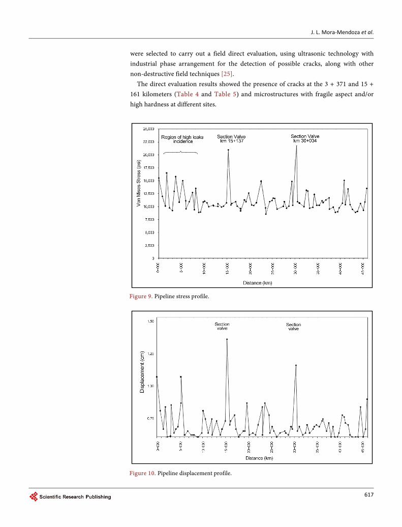
J L Mora-Mendoza et al
622
[12] Linton VM and Laycock NJ (2008) Stress Corrosion Cracking of a Vinyl Chloride Stripper Vessel Materials Performance 47 74-79
[13] Loginow AW (1989) Stress Corrosion Cracking of Steel in Liquefied Ammonia Servicemdash A Recapitulation National Board Classic Series National Board Bulletin
[14] Cottis RA (2000) Stress Corrosion CrackingmdashGuides to Good Practice in Corrosion Control The National Physical Laboratory 1-16 wwwnplcouk
[15] Guidance for Inspection of and Leak Detection in Liquid Ammonia Pipelines 2008 Edition Issue 2013 Fertilizer Europe
[16] ASTM E3-11 Standard Guide for Preparation of Metallographic Specimens
[17] ASTM E340-15 Standard Practice for Macroetching Metals and Alloys
[18] ASTM E407-07 (2015) Standard Practice for Microetching Metals and Alloys
[19] ASTM E112-13 Standard Test Methods for Determining Average Grain Size
[20] ASTM E8E8M-15a Standard Test Methods for Tension Testing of Metallic Materials
[21] ASTM E10-15a Standard Test Method for Brinell Hardness of Metallic Materials
[22] ASTM E140-12b Standard Hardness Conversion Tables for Metals Relationship among Brinell Hardness Vickers Hardness Rockwell Hardness Superficial Hardness Noop Hard- ness Scleroscope Hardness and Leeb Hardness
[23] NACE SP0102-2010 Standard Practice In-Line Inspection of Pipelines
[24] ASME B314-2009 Pipeline Transportation Systems for Liquid Hydrocarbons and Other Liquids
[25] ASTM E213-14 Standard Practice for Ultrasonic Testing of Metal Pipe and Tubing
Submit or recommend next manuscript to SCIRP and we will provide best service for you
Accepting pre-submission inquiries through Email Facebook LinkedIn Twitter etc A wide selection of journals (inclusive of 9 subjects more than 200 journals) Providing 24-hour high-quality service User-friendly online submission system Fair and swift peer-review system Efficient typesetting and proofreading procedure Display of the result of downloads and visits as well as the number of cited articles Maximum dissemination of your research work
Submit your manuscript at httppapersubmissionscirporg Or contact msascirporg
- Evaluation of Stress Corrosion Cracking Damage to an API 5L X52 Pipeline Transporting Ammonia A Case Study
- Abstract
- Keywords
- 1 Introduction
- 2 Background
- 3 Initial Field and Laboratory Studies
-
- 31 Metallographic Analyses
- 32 Total Repair Actions
- 33 Pipeline Flexibility
- 34 Direct Inspection
- 35 Evaluation of the Ammonia Pipeline
-
- 4 Conclusions
- References
-