![Evaluation of Field of View Calibration Techniques for ... · and virtual views, only few quantitative calibration techniques have been proposed. For instance, Gilson et al. [GFG09]](https://static.fdocuments.in/doc/165x107/5f288b9736467652320b06fe/evaluation-of-field-of-view-calibration-techniques-for-and-virtual-views-only.jpg)
Evaluation of pairwise calibration techniques for range … · A. Lejeune, D. G ROGNA, M. V AN D...
6
A. Lejeune, D. GROGNA, M. VAN DROOGENBROECK and J. VERLY. Evaluation of pairwise calibration techniques for range cameras and their ability to detect a misalignment. In International Conference on 3D Imaging (IC3D), Liège, Belgium, December 2014. EVALUATION OF PAIRWISE CALIBRATION TECHNIQUES FOR RANGECAMERAS AND THEIR ABILITY TO DETECT A MISALIGNMENT Antoine Lejeune, David Grogna, Marc Van Droogenbroeck and Jacques Verly Department of Electrical Engineering and Computer Science, University of Liège, Belgium ABSTRACT Many applications require the use of multiple cameras to cover a large volume. In this paper, we evaluate several pairwise calibration techniques dedicated to multiple range cameras. We compare the precision of a self-calibration technique based on the movement in front of the cameras to object based cal- ibration. While the self-calibration technique is less precise than its counterparts, it yields a first estimation of the trans- formation between the cameras and permits to detect when the cameras become mis-aligned. Therefore, this technique is useful in a practical situations. 1. INTRODUCTION Commodity range cameras have recently permitted to develop new applications by providing dense depth maps at real-time frame rate (> 15fps). Some computer vision problems can be solved with such cameras, such as human pose estima- tion [20], augmented reality, and virtual reality. Indeed, there is no longer a need to infer 3D information from colorimetric information. Any application that operates in large environments re- quires multiple cameras to work robustly over the whole vol- ume. Examples of such applications include immersive vir- tual environment, telepresence set-ups, and gait analysis of humans over long distances [17]. Range cameras capable of recording at real-time frame rate operate only for a short distance range. The Microsoft Kinect can measure depths up to 10 meters but provide a pre- cision on the order of the centimeter only for depth up to a few meters [14]. Time-of-flight cameras, such as the PMD CamCube 2.0, have a physical limit on the maximum depth that can be measured unambiguously. This limit is usually well below 10 meters. Therefore, multiple cameras have to be used to correctly cover areas with a size larger than 10 me- ters. To aggregate the information captured from all the cam- eras, their relative positions need to be estimated. This takes the form of pairwise rigid body transformations (translation and rotation between two cameras). The difficulties for esti- mating this transformation originate from establishing point correspondences between the images of the cameras. For ro- (a) (b) Fig. 1: Human seen by two range cameras. Black dots in im- age (b) represent the projection of pixels also found in image (a). bust correspondences, a calibration object such as a chess- board is often used. The calibration object also provides Eu- clidean constraints, which are required for a “metric” calibra- tion of the cameras. In this paper, we evaluate several methods for pairwise calibration of range cameras, including one self-calibration technique based on movement detection, which can also be used to detect when the cameras become mis-aligned. In Section 2, we first review existing calibration techniques and the characteristics of range cameras. In Section 3, we de- scribe the pairwise calibration methods used in this paper. In Section 4, we compare the results of the techniques. The results presented in Section 4 show that techniques directly based on the depth values are less precise than a tech- nique based on the detection of a calibration object in a color image. However, they permit to obtain a first estimation of the rigid body transformation and to detect a misalignment of the cameras by only using the movement observed in the scene. 2. RELATED WORK 2.1. Calibration and self-calibration The problem of camera calibration has been extensively an- alyzed for color cameras. Most methods require the use of a calibration pattern, such as a chessboard [3], and perform the pairwise calibration as well as the intrinsic calibration of each individual camera. The calibration object ensures that
-
Upload
trinhquynh -
Category
Documents
-
view
214 -
download
1
Transcript of Evaluation of pairwise calibration techniques for range … · A. Lejeune, D. G ROGNA, M. V AN D...

A. Lejeune, D. GROGNA, M. VAN DROOGENBROECK and J. VERLY. Evaluation of pairwise calibration techniques for range camerasand their ability to detect a misalignment. In International Conference on 3D Imaging (IC3D), Liège, Belgium, December 2014.
EVALUATION OF PAIRWISE CALIBRATION TECHNIQUES FOR RANGE CAMERAS ANDTHEIR ABILITY TO DETECT A MISALIGNMENT
Antoine Lejeune, David Grogna, Marc Van Droogenbroeck and Jacques Verly
Department of Electrical Engineering and Computer Science, University of Liège, Belgium
ABSTRACT
Many applications require the use of multiple cameras to covera large volume. In this paper, we evaluate several pairwisecalibration techniques dedicated to multiple range cameras.We compare the precision of a self-calibration technique basedon the movement in front of the cameras to object based cal-ibration. While the self-calibration technique is less precisethan its counterparts, it yields a first estimation of the trans-formation between the cameras and permits to detect whenthe cameras become mis-aligned. Therefore, this technique isuseful in a practical situations.
1. INTRODUCTION
Commodity range cameras have recently permitted to developnew applications by providing dense depth maps at real-timeframe rate (> 15fps). Some computer vision problems canbe solved with such cameras, such as human pose estima-tion [20], augmented reality, and virtual reality. Indeed, thereis no longer a need to infer 3D information from colorimetricinformation.
Any application that operates in large environments re-quires multiple cameras to work robustly over the whole vol-ume. Examples of such applications include immersive vir-tual environment, telepresence set-ups, and gait analysis ofhumans over long distances [17].
Range cameras capable of recording at real-time framerate operate only for a short distance range. The MicrosoftKinect can measure depths up to 10 meters but provide a pre-cision on the order of the centimeter only for depth up to afew meters [14]. Time-of-flight cameras, such as the PMDCamCube 2.0, have a physical limit on the maximum depththat can be measured unambiguously. This limit is usuallywell below 10 meters. Therefore, multiple cameras have tobe used to correctly cover areas with a size larger than 10 me-ters.
To aggregate the information captured from all the cam-eras, their relative positions need to be estimated. This takesthe form of pairwise rigid body transformations (translationand rotation between two cameras). The difficulties for esti-mating this transformation originate from establishing pointcorrespondences between the images of the cameras. For ro-
(a) (b)
Fig. 1: Human seen by two range cameras. Black dots in im-age (b) represent the projection of pixels also found in image(a).
bust correspondences, a calibration object such as a chess-board is often used. The calibration object also provides Eu-clidean constraints, which are required for a “metric” calibra-tion of the cameras.
In this paper, we evaluate several methods for pairwisecalibration of range cameras, including one self-calibrationtechnique based on movement detection, which can also beused to detect when the cameras become mis-aligned.
In Section 2, we first review existing calibration techniquesand the characteristics of range cameras. In Section 3, we de-scribe the pairwise calibration methods used in this paper. InSection 4, we compare the results of the techniques.
The results presented in Section 4 show that techniquesdirectly based on the depth values are less precise than a tech-nique based on the detection of a calibration object in a colorimage. However, they permit to obtain a first estimation of therigid body transformation and to detect a misalignment of thecameras by only using the movement observed in the scene.
2. RELATED WORK
2.1. Calibration and self-calibration
The problem of camera calibration has been extensively an-alyzed for color cameras. Most methods require the use ofa calibration pattern, such as a chessboard [3], and performthe pairwise calibration as well as the intrinsic calibration ofeach individual camera. The calibration object ensures that

A. Lejeune, D. GROGNA, M. VAN DROOGENBROECK and J. VERLY. Evaluation of pairwise calibration techniques for range camerasand their ability to detect a misalignment. In International Conference on 3D Imaging (IC3D), Liège, Belgium, December 2014.
(a) Microsoft Kinect (b) PMD CamCube 2.0
Fig. 2: Range cameras used in this work.
the correspondences between the images are correct.
More recently, several authors proposed calibration tech-niques based on a laser pointer [6, 21]. The cameras recordthe successive positions of the light to form a virtual calibra-tion pattern which can be used to perform the pairwise cali-bration of the cameras. A variation of this technique has al-ready been used for the calibration of a network of MicrosoftKinect cameras [1].
Azarbayejani et al. [2] proposed a self-calibration tech-nique for wide baseline stereo system. It is based on the detec-tion of the face and the hands of the user in front of the cam-era. The estimated parameters are thus strongly constrainedby the imposed position of the cameras and the content of thescene.
For laser range finders, Glas et al. [9] proposed an au-tomatic self-calibration technique in crowded environment.They used an elliptical shape model to estimate, track, andmatch the positions of the users for each sensor. The field ofview of all sensors are within the same plane, meaning thatthere is only a single angle of rotation to estimate.
Kaenchan et al. [13] proposed an iterative technique forMicrosoft Kinect cameras based on an initial guess of thetransformation. The technique uses the limbs’ locations givenby the OpenNI framework for point correspondences. How-ever, they don’t evaluate the performance of their calibrationprocedure.
For cameras close to each other, there exists various tech-niques dedicated to range data that yield accurate results. Theiterative closest point algorithm [18] estimates the rigid bodytransformation by iteratively matching the closest 3D pointstogether. Kinect Fusion [12] is a nonlinear minimization ofthe reprojection error between two depth maps.
Most techniques developed for color cameras use the re-projection error as the evaluation metric. While this metricis good for RGB and gray-level images, it isn’t adequate forsensors measuring geometric information. In this paper, weevaluate the self-calibration accuracy according to the trans-lation and angular error between the cameras.
2.2. Range cameras
A range camera records, for each pixel p, the depth Z (p)of the corresponding element of the scene. If the intrinsicparameters of the camera (focal length and optical center) areknown, one can convert the point (p, Z (p)) to a 3D real-world coordinate in a reference frame located at the opticalcenter of the camera [10]. Thus, these cameras permit a directmetric reconstruction of the scene.
In this paper, we use two different models of range cam-eras: the Microsoft Kinect (version 1) and the PMD CamCube2.0 (see Figure 2). These cameras are based on different ac-quisition techniques. The Microsoft Kinect uses a structured-light technique to estimate the depth [8] and the PMD Cam-Cube 2.0 is a time-of-flight (ToF) camera which estimates thedepth by measuring the phase shift between the transmittedand received modulated infrared signals [22].
We note that these cameras can have significant noise orno data at all for some pixels. This happens when not enoughlight is reflected back to the sensors. This can be due to badreflective properties or a large angle of incidence with theintercepted surface in the scene. Also, the amount of noisecan be different for each pixel of an image. Several mod-els have been proposed to characterize this noise. The Mi-crosoft Kinect has a noise that increases quadratically withthe depth [14], and ToF cameras have a noise that increaseswith the inverse of the amplitude of the signal [7].
There can be significant artifacts when using more thanone camera of the same model: the transmitted signals can in-terfere with each other. Two Microsoft Kinect can fail to mea-sure depth when their fields of view largely overlap. Schröderet al. [19] proposed fast rotating discs to create a time divi-sion multiple access scenario. Butler et al. [4] reduced theinterference between the cameras by using an electric motorwhich make them vibrate. For ToF cameras, the modulationfrequency of the signal can be changed in some cameras. Inthis case, there is no problem in using more than one cam-era. When two cameras use the same modulation frequency,Castabeda proposed a technique which still permits the use ofseveral cameras in a wide baseline stereo set-up [5]. In thispaper, we don’t use any such technique. We limit our study tothe pairwise calibration of the cameras.
Here, we assume that the intrinsic parameters of the rangecameras are already calibrated. We note that these parametershave to be determined only once and that the Microsoft Kinectcamera is factory calibrated. For ToF cameras, there existsdedicated calibration techniques, e.g. [15].
3. PAIRWISE CALIBRATION TECHNIQUES
The goal of the pairwise calibration is to find the rigid bodytransformation that brings points of one camera to the refer-ence coordinate frame of the second camera,
P(2) = RP(1) + t (1)

A. Lejeune, D. GROGNA, M. VAN DROOGENBROECK and J. VERLY. Evaluation of pairwise calibration techniques for range camerasand their ability to detect a misalignment. In International Conference on 3D Imaging (IC3D), Liège, Belgium, December 2014.
(a) Chessboard (b) Colored plane object
Fig. 3: Calibration objects used in this work.
where R and t are the rotation matrix and translation vectorof the rigid body transformation, P(1) is a point expressed inthe coordinate frame of the first camera, and P(2) is the samepoint expressed in the coordinate frame of the second camera.
The rigid body transformation can be computed from twocorresponding 3D point clouds
{P
(1)i ,P
(2)i
}using the Kab-
sch algorithm [16]. This technique minimizes the least-squareloss function
∑
i
wi
∥∥∥P(2) −RP(1) − t∥∥∥2
. (2)
We use this algorithm, combined to a RANSAC procedure, toestimate the rigid body transformation.
3.1. Technique 1: chessboard pattern
Our first pairwise calibration technique is the one implementedin the OpenCV library [3]. This technique is based on gray-level images and uses a calibration pattern such as a chess-board (see Figure 3a) to establish point correspondences be-tween the images. Note that we use the RGB image of theMicrosoft Kinect and the intensity image of the PMD Cam-Cube 2.0 to detect the corners of the chessboard.
This technique is based on epipolar geometry [10] andperforms a non-linear minimization of the reprojection errorof the detected corners. The final reprojection error is usuallysmaller than one pixel.
3.2. Technique 2: plane
The second technique is based on a colored plane (see Fig-ure 3b). We use both the texture and the depth information toperform the pairwise calibration. The pixels belonging to theplane are detected in the color image by a floodfill algorithmusing the color of the plane.
We obtain the 3D point correspondences{P
(1)i ,P
(2)i
}by
estimating the center of the planes in both images using
P(k)i =
∑i Z
(k) (pi)2P(k) (pi)∑
i Z(k) (pi)
2 , (3)
where Z(k) (pi) is the depth value of the pixel pi for camerak and P(k) (pi) the 3D point corresponding to the pixel pi.By weighting each point with its squared depth, we take intoconsideration the fact that a larger distance between a pixeland the camera correspond to a larger surface encompassedby the pixel in the scene. In other words, the density of the3D points decreases with their depth.
3.3. Technique 3: movement detection
The third technique is based on movement detection. Wetrack the objects in movement in the two cameras and estab-lish the point correspondences from the center of mass of theobserved objects. The processing pipeline used for movementdetection and matching is summarized in Figure 4. We per-form a background subtraction on the images to retrieve thevarious objects in the scene. We model them using a mul-tivariate normal distribution. We track the objects by usinga similarity measure and their last position. The objects arematched between the two cameras using a similarity measure.
3.3.1. Background subtraction
For background subtraction, we base our technique on a sim-ple background model where we record the largest depth seenat each pixel of the image. The depth background B(k)
Z (p) ofcamera k at pixel p can be expressed as
B(k)Z (p) = max
j
(Z
(k)j (p)
), j < NBG , (4)
where Z(k)j is j-th range image captured by camera i and
NBG is the number of images used to learn the background.The foreground F (k) is obtained by simply comparing thecurrent range image with the background model,
F (k) (p) =
true if Z(k) (p) is valid and∣∣B(k) (p)− Z(k) (p)∣∣ > λσ(k) (p)
false otherwise,(5)
where σ(k) is an image indicating the relative level of noiseat each pixel, λ is a parameter of the technique. For the Mi-crosoft Kinect, we use σ(k)
kinect (p) =(Z(k) (p)
)2and λkinect =
0.05. For the PMD CamCube 2.0, we use σ(k)tof (p) =
(A(k) (p)
)−1
and λ = 70, where A denotes the amplitude image given bythe camera.
There can be noise in the foreground mask, especiallyaround the edges in the case of the Microsoft Kinect. To re-move false positive and segment the foreground in its differentpart, we use a connected component analysis algorithm on theforeground mask and the depth. We then reject the smallestcomponents. Our connected component algorithm is basedon the floodfill algorithm: two neighboring pixels which arein the foreground mask and whose depth difference is below a
A. Lejeune, D. GROGNA, M. VAN DROOGENBROECK and J. VERLY. Evaluation of pairwise calibration techniques for range camerasand their ability to detect a misalignment. In International Conference on 3D Imaging (IC3D), Liège, Belgium, December 2014.
Camera 1
Camera 2
Backgroundsubtraction
Backgroundsubtraction
Modelingand tracking
Modelingand tracking
MatchingRigid body
transformationestimation
Fig. 4: Processing pipeline for pairwise calibration based on movement detection.
certain threshold are in the same component. The connectedcomponent analysis also permits to correctly separate two ob-jects crossing each other.
3.3.2. Modeling and similarity measure
We model an object Oi by its center of mass µi and its co-variance Σi. These parameters constitute a multivariate nor-mal distribution. As a single image is only able to capturethe front side of the object and not its whole volume, the es-timated parameters will be biased towards the camera. To re-duce this bias, we compute µi only using the border pixels ofthe object. Indeed, for cylinder shaped object, the borders willbe symmetrically distributed around the center of mass. Thecenter of mass and the covariance are estimated by weightingpixels according to their local density as in Equation (3).
To track an object within a single camera, we use an esti-mation of the speed of the object to predict its distribution inthe next image, and we use the Kullback-Leibler divergenceas a similarity measure.
As the position of the objects in the two cameras can besignificantly different, we perform an inter-camera matchingby comparing only the covariance of the objects. The centersof mass of the objects matched between the two cameras areused to make a new point correspondence for pairwise cali-bration.
3.3.3. Misalignment detection
During the operation of the cameras, they can become mis-aligned. For example, this can happen when the cameras ortheir support are bumped into or when they are moved inad-vertently. Our third calibration technique can then be used asa basis for misalignment detection.
We constantly add the new detected correspondences whilewe remove those which are outdated. Then, we comparethe last ground truth rigid body transformation to the oneestimated using the detected movement. To do so, we usethe translation and angular error between the transformations.Denoting by (RGT , tGT ) the transformation between the cam-eras, and by (R?, t?) the transformation estimated using the
1.6m
(a)
0.28m
(b)
6m
(c)
1m
2m
(d)
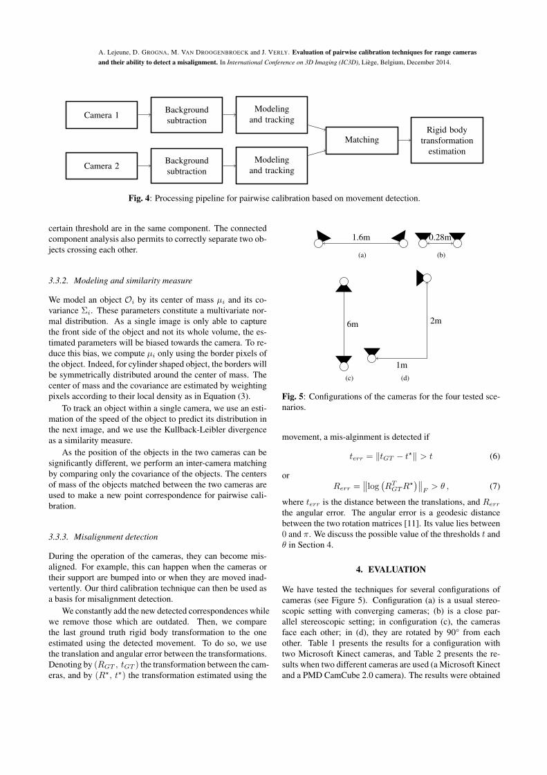
Fig. 5: Configurations of the cameras for the four tested sce-narios.
movement, a mis-alginment is detected if
terr = ‖tGT − t?‖ > t (6)
orRerr =
∥∥log(RT
GTR?)∥∥
F> θ , (7)
where terr is the distance between the translations, and Rerr
the angular error. The angular error is a geodesic distancebetween the two rotation matrices [11]. Its value lies between0 and π. We discuss the possible value of the thresholds t andθ in Section 4.
4. EVALUATION
We have tested the techniques for several configurations ofcameras (see Figure 5). Configuration (a) is a usual stereo-scopic setting with converging cameras; (b) is a close par-allel stereoscopic setting; in configuration (c), the camerasface each other; in (d), they are rotated by 90° from eachother. Table 1 presents the results for a configuration withtwo Microsoft Kinect cameras, and Table 2 presents the re-sults when two different cameras are used (a Microsoft Kinectand a PMD CamCube 2.0 camera). The results were obtained

A. Lejeune, D. GROGNA, M. VAN DROOGENBROECK and J. VERLY. Evaluation of pairwise calibration techniques for range camerasand their ability to detect a misalignment. In International Conference on 3D Imaging (IC3D), Liège, Belgium, December 2014.
Configuration (a) (b) (c) (d)Translation error (in meter)
Technique 1 0 0 0 0Technique 2 0.094 0.057 0.047 0.155Technique 3 0.076 0.069 0.128 0.189
Angular error (in degree)Technique 1 0 0 0 0Technique 2 2.59 1.34 0.45 5.53Technique 3 2.49 1.37 1.96 3.58
Table 1: Errors obtained with two Microsoft Kinect camerascompared to a pairwise calibration with a chessboard pattern.
on sequences with duration comprised between one and twominutes.
With two Microsoft Kinect cameras, techniques 2 and 3have comparable results. We see that configuration (d) yieldsthe worse estimation. We believe that this occurs becausethe overlap between the fields of vision of the cameras is thesmallest in this scenario.
With different cameras, technique 2 performs better thantechnique 3, which leads to larger translation errors. This maybe explained by the fact that the movement extraction algo-rithm failed more often with the PMD CamCube 2.0, partlybecause areas of the scene are located at a depth larger thanthe camera unambiguous measurement range, and partly be-cause the angle of view of this camera is smaller (the objectsweren’t fully contained inside its field of view). It is alsoprobable that a better background subtraction algorithm andpreprocessing techniques for the PMD CamCube 2.0 camerawould improve the results.
We have attempted to increase the performance of ourtechnique by using an iterative closest point algorithm aftera first estimation was obtained. However, our attempts didn’tyield significant improvements. In the case of cameras facingeach other (configuration (c)), the results were always worse.This can be explained by the lack of corresponding points be-tween the two cameras.
For misalignment detection, the thresholds on the transla-tion and angular error should be chosen larger than the errorsreported in Table 1 and 2, according to the configuration ofthe cameras.
5. CONCLUSION
In this paper, we have just reviewed several techniques forpairwise calibration of two range cameras. The common tech-nique based on a chessboard pattern was compared to a tech-nique based on a colored plane calibration object and a self-calibration technique based on movement detection in the scene.We have shown that the techniques that use the range valuesfor calibration fail to reach the same level of precision as that
Configuration (a) (b) (c) (d)Translation error (in meter)
Technique 1 0 0 0 0Technique 2 0.176 0.042 0.044 0.064Technique 3 0.10 0.223 0.169 0.339
Angular error (in degree)Technique 1 0 0 0 0Technique 2 4.42 4.94 0.54 1.61Technique 3 3.46 2.88 1.95 11.28
Table 2: Errors obtained with one Microsoft Kinect and onePMD CamCube 2.0 compared to a pairwise calibration witha chessboard pattern.
of the chessboard technique. However, they are able to pro-vide a good approximation in some cases.
We recommend to use the self-calibration technique thatuses the observed movement only when it is impossible to cal-ibrate the cameras with a more accurate technique. However,this technique can be used for misalignment detection and canprovide a temporary calibration when a misalignment is de-tected.
Acknowledgment. Antoine Lejeune and David Grogna areunder a contract funded by the European Regional Develop-ment Fund (ERDF) program of the Walloon Region, Belgium.
6. REFERENCES
[1] D. Alexiadis, D. Zarpalas, and P. Daras. Real-time, full3-D reconstruction of moving foreground objects frommultiple consumer depth cameras. IEEE Transactionson Multimedia, 15(2):339–358, February 2013.
[2] A. Azarbayejani and A. Pentland. Real-time self-calibrating stereo person tracking using 3-D shape esti-mation from blob features. In IEEE International Con-ference on Pattern Recognition (ICPR), volume 3, pages627–632, August 1996.
[3] G. Bradski. The OpenCV Library. Dr. Dobb’s Journalof Software Tools, 2000.
[4] A. Butler, S. Izadi, O. Hilliges, D. Molyneaux,S. Hodges, and D. Kim. Shake’n’sense: Reducing inter-ference for overlapping structured light depth cameras.In SIGCHI Conference on Human Factors in Comput-ing Systems, CHI ’12, pages 1933–1936, New York, NY,USA, May 2012. ACM.
[5] V. Castaneda. Constructive interference for Multi-viewTime-of-Flight acquisition. PhD thesis, Technische Uni-versitat München, 2012.

A. Lejeune, D. GROGNA, M. VAN DROOGENBROECK and J. VERLY. Evaluation of pairwise calibration techniques for range camerasand their ability to detect a misalignment. In International Conference on 3D Imaging (IC3D), Liège, Belgium, December 2014.
[6] X. Chen, J. Davis, and P. Slusallek. Wide area cameracalibration using virtual calibration objects. In IEEE In-ternational Conference on Computer Vision and PatternRecognition (CVPR), volume 2, pages 520–527, June2000.
[7] M. Frank, M. Plaue, H. Rapp, U. Kothe, B. Jahne, andF. Hamprecht. Theoretical and experimental error anal-ysis of continuous-wave time-of-flight range cameras.Optical Engineering, 48(1), January 2009.
[8] B. Freedman, A. Shpunt, M. Machline, and Y. Arieli.Depth mapping using projected patterns, 2010. USPatent Application 20100118123.
[9] D. Glas, T. Miyashita, H. Ishiguro, and N. Hagita. Au-tomatic position calibration and sensor displacement de-tection for networks of laser range finders for humantracking. In IEEE/RSJ International Conference on In-telligent Robots and Systems (IROS), pages 2938–2945,Taipei, Taiwan, October 2010.
[10] R. Hartley and A. Zisserman. Multiple View Geometryin Computer Vision. Cambridge University Press, sec-ond edition, 2004.
[11] D. Huynh. Metrics for 3d rotations: Comparison andanalysis. Journal of Mathematical Imaging and Vision,35(2):155–164, 2009.
[12] S. Izadi, R. Newcombe, D. Kim, O. Hilliges,D. Molyneaux, S. Hodges, P. Kohli, A. Davison, andA. Fitzgibbon. KinectFusion: Real-time dynamic 3Dsurface reconstruction and interaction. In ACM SIG-GRAPH Talks, Vancouver, Canada, 2011.
[13] S. Kaenchan, P. Mongkolnam, B. Watanapa, andS. Sathienpong. Automatic multiple kinect cameras set-ting for simple walking posture analysis. In Interna-tional Computer Science and Engineering Conference(ICSEC), pages 245–249, September 2013.
[14] K. Khoshelham and S. Elberink. Accuracy and resolu-tion of Kinect depth data for indoor mapping applica-tions. Sensors, 12(2):1437–1454, February 2012.
[15] M. Lindner, I. Schiller, A. Kolb, and R. Koch. Time-of-Flight sensor calibration for accurate range sens-ing. Computer Vision and Image Understanding,114(12):1318–1328, 2010.
[16] L. Markley. Attitude determination using vector obser-vations and the singular value decomposition. The Jour-nal of the Astronautical Sciences, 36(3):245–258, July1988.
[17] S. Piérard, R. Phan-Ba, V. Delvaux, P. Maquet, andM. Van Droogenbroeck. GAIMS: a powerful gait anal-ysis system satisfying the constraints of clinical rou-tine. Multiple Sclerosis Journal, 19(S1):359, October2013. Proceedings of ECTRIMS/RIMS 2013 (Copen-hagen, Denmark), P800.
[18] S. Rusinkiewicz and M. Levoy. Efficient variants ofthe ICP algorithm. In International Conference on 3DDigital Imaging and Modeling (3DIM), pages 145–152,Quebec City, Canada, June 2001.
[19] Y. Schröder, A. Scholz, K. Berger, K. Ruhl, S. Guthe,and M. Magnor. Multiple Kinect studies. Technical Re-port 09-15, ICG, October 2011.
[20] J. Shotton, A. Fitzgibbon, M. Cook, T. Sharp, M. Finoc-chio, R. Moore, A. Kipman, and A. Blake. Real-timehuman pose recognition in parts from single depth im-ages. In IEEE International Conference on ComputerVision and Pattern Recognition (CVPR), pages 1297–1304, Providence, Rhode Island, USA, June 2011.
[21] T. Svoboda, D. Martinec, and T. Pajdla. A convenientmulti-camera self-calibration for virtual environments.PRESENCE: Teleoperators and Virtual Environments,14(4):407–422, August 2005.
[22] Z. Xu, R. Schwarte, H. Heinol, B. Buxbaum, andT. Ringbeck. Smart pixel-photonic mixer device (PMD):New system concept of a 3D-imaging camera-on-a-chip.In International Conference on Mechatronics and Ma-chine Vision in Practice (M2VIP), pages 259–264, Nan-jing, China, September 1998.