Evaluation of Microcracking in Two Carbon-Fiber… · Evaluation of Microcracking in Two...
21
NASA/TM--2001-211194 Evaluation of Microcracking in Two Carbon-Fiber/Epoxy-Matrix Composite Cryogenic Tanks A.J. Hodge Marshall Space Flight Center, Marshall Space Flight Center, Alabama August 2001 https://ntrs.nasa.gov/search.jsp?R=20010080458 2018-06-29T20:20:46+00:00Z
Transcript of Evaluation of Microcracking in Two Carbon-Fiber… · Evaluation of Microcracking in Two...

NASA/TM--2001-211194
Evaluation of Microcracking in
Two Carbon-Fiber/Epoxy-Matrix
Composite Cryogenic Tanks
A.J. Hodge
Marshall Space Flight Center, Marshall Space Flight Center, Alabama
August 2001
https://ntrs.nasa.gov/search.jsp?R=20010080458 2018-06-29T20:20:46+00:00Z
The NASA STI Program Office...in Profile
Since its founding, NASA has been dedicated to
the advancement of aeronautics and spacescience. The NASA Scientific and Technical
Information (STI) Program Office plays a key
part in helping NASA maintain this importantrole.
The NASA STI Program Office is operated by
Langley Research Center, the lead center forNASA's scientific and technical information. The
NASA STI Program Office provides access to the
NASA STI Database, the largest collection of
aeronautical and space science STI in the world. The
Program Office is also NASA's institutional
mechanism for disseminating the results of its
research and development activities. These results
are published by NASA in the NASA STI Report
Series, which includes the following report types:
TECHNICAL PUBLICATION. Reports of
completed research or a major significant phase
of research that present the results of NASA
programs and include extensive data or
theoretical analysis. Includes compilations of
significant scientific and technical data and
information deemed to be of continuing reference
value. NASA' s counterpart of peer-reviewed
formal professional papers but has less stringent
limitations on manuscript length and extent of
graphic presentations.
TECHNICAL MEMORANDUM. Scientific and
technical findings that are preliminary or of
specialized interest, e.g., quick release reports,
working papers, and bibliographies that containminimal annotation. Does not contain extensive
analysis.
CONTRACTOR REPORT. Scientific and
technical findings by NASA-sponsored
contractors and grantees.
CONFERENCE PUBLICATION. Collected
papers from scientific and technical conferences,
symposia, seminars, or other meetings sponsored
or cosponsored by NASA.
SPECIAL PUBLICATION. Scientific, technical,
or historical information from NASA programs,
projects, and mission, often concerned with
subjects having substantial public interest.
TECHNICAL TRANSLATION.
English-language translations of foreign scientific
and technical material pertinent to NASA'smission.
Specialized services that complement the STI
Program Office's diverse offerings include creating
custom thesauri, building customized databases,
organizing and publishing research results...even
providing videos.
For more information about the NASA STI Program
Office, see the following:
• Access the NASA STI Program Home Page at
http ://www.sti.nasa.go v
• E-mail your question via the Internet to
help @ sti.nasa.gov
• Fax your question to the NASA Access Help
Desk at (301) 621 0134
• Telephone the NASA Access Help Desk at (301)621 0390
Write to:
NASA Access Help Desk
NASA Center for AeroSpace Information7121 Standard Drive
Hanover, MD 21076 1320

NASA/TM--2001-211194
Evaluation of Microcracking in
Two Carbon-Fiber/Epoxy-Matrix
Composite Cryogenic Tanks
A.J. Hodge
Marshall Space Flight Center, Marshall Space Flight Center, Alabama
National Aeronautics and
Space Administration
Marshall Space Flight Center • MSFC, Alabama 35812
August 2001

NASA Center for AeroSpace Information7121 Standard Drive
Hanover, MD 21076 1320
(301) 621 0390
Available from:
ii
National Technical Information Service
5285 Port Royal Road
Springfield, VA 22161
(703) 487 4650

TABLE OF CONTENTS
1. INTRODUCTION ........................................................................................................................... 1
2. TESTING ........................................................................................................................................ 2
2.1 Composite Conformal, Cryogenic, Common Bulkhead, Aerogel-Insulated Tank ................. 2
2.2 X-33 Liquid Hydrogen Tank .................................................................................................. 2
3. TEST RESULTS AND ANALYSIS ................................................................................................ 4
3.1 Mathematical Model of Microcracking .................................................................................. 4
3.2 Composite Conformal, Cryogenic, Common Bulkhead, Aerogel-Insulated Tank ................. 8
3.3 X-33 Liquid Hydrogen Tank .................................................................................................. 9
4. CONCLUSIONS ............................................................................................................................. 11
REFERENCES ...................................................................................................................................... 12
iii

LIST OF FIGURES
°
2.
3.
4.
5.
6.
7.
8.
Shear lag model ........................................................................................................................... 5
Stresses within a cracked ply of a composite laminate with various crack lengths (2h) ............. 7
Crack in CBAT laminate (x-y plane) .......................................................................................... 8
(a) First microcrack occurs on void and (b) failure occurs on the same void ............................. 8
Crack density in (+6/-6)s ply of CBAT laminate versus applied tensile load ............................. 9
Crack density in (+6/-6) ply of CBAT laminate versus applied tensile load .............................. 9
Crack density in hoop ply of X-33 laminate versus applied tensile load ................................... 10
Crack density in longitudinal ply of X-33 laminate versus applied tensile load ........................ 10
iv

LIST OF ACRONYMS AND ABBREVIATIONS
CBAT
CLT
CTE
LH 2
MSFC
Composite Conformal, Cryogenic, Common Bulkhead, Aerogel-Insulated Tank
Classical Lamination Theory
coefficient of thermal expansion
liquid hydrogen
Marshall Space Flight Center
V

NOMENCLATURE
A
b
d
C
E
F((y)
G
h
H
Q
U
V
U
W
AT
O-
microcrack surface area
uncracked layer of laminate
transverse, cracked layer of laminate
Integration constant
modulus
sum of the mechanically and thermally induced stress
critical strain energy release rate
half the distance between existing cracks
constant
geometry factor
displacement in the b layer
displacement in the d layer
strain energy
work
change in temperature
stress
vi

TECHNICAL MEMORANDUM
EVALUATION OF MICROCRACKING IN TWO CARBON-FIBER/EPOXY-MATRIX
COMPOSITE CRYOGENIC TANKS
1. INTRODUCTION
When a composite laminate is stressed, several damage modes such as matrix microcracking,
delamination, and fiber breakage are often observed before final failure. Matrix microcracking is gener-
ally the first damage mode observed in a laminated composite. Microcracking generally occurs at load
conditions well below final fracture and generally has little effect on the overall strength of the compos-
ite laminate. However, microcracking can lead to other damage modes, alter the elastic properties, and
increase the laminates' permeability to gases and liquids. Increased permeability is of particular concern
when the composite is used as a pressure vessel.
Microcracks typically initiate in plys transversely oriented to the applied load. The transverse
load is a result of both mechanical and thermal load. Because of the coefficient of thermal expansion
(CTE) mismatch between axially and transversely oriented plys, high residual tensile stresses occur in
the transverse direction of a composite ply when the composite laminate is cooled following cure.
Further cooling in cryogenic applications exacerbates this condition. Microcracking can occur in some
laminates due to thermal effects alone.
The microcracking characteristics of two different composite tanks were evaluated. The micro-
structure of the X-33 liquid hydrogen (LH2) tank was examined. Laminates representative of the
Marshall Space Flight Center (MSFC) Composite Conformal, Cryogenic, Common Bulkhead, Aerogel-
Insulated Tank (CBAT) were also examined. Tensile tests were performed on the laminates to induce
microcracking. The tensile tests were performed at ambient and cryogenic temperatures. The microcrack
density and applied stress were recorded. A model successfully predicted microcrack density in the
X-33 laminate but was less successful with the CBAT laminate.
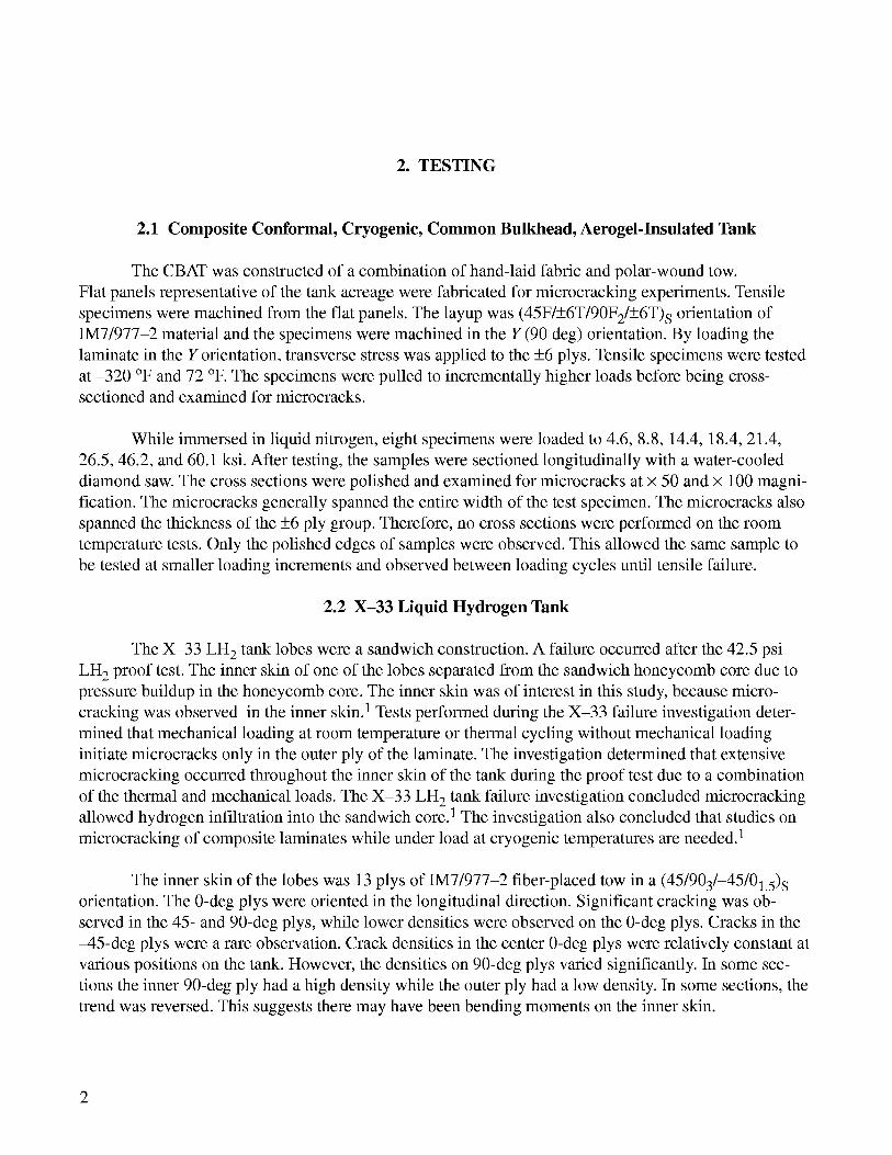
2. TESTING
2.1 Composite Conformal, Cryogenic, Common Bulkhead, Aerogel-Insulated Tank
The CBAT was constructed of a combination of hand-laid fabric and polar-wound tow.
Flat panels representative of the tank acreage were fabricated for microcracking experiments. Tensile
specimens were machined from the flat panels. The layup was (45F/+6T/90F2/+6T) s orientation of
IM7/977-2 material and the specimens were machined in the Y (90 deg) orientation. By loading the
laminate in the Y orientation, transverse stress was applied to the +6 plys. Tensile specimens were tested
at -320 °F and 72 °F. The specimens were pulled to incrementally higher loads before being cross-
sectioned and examined for microcracks.
While immersed in liquid nitrogen, eight specimens were loaded to 4.6, 8.8, 14.4, 18.4, 21.4,
26.5, 46.2, and 60.1 ksi. After testing, the samples were sectioned longitudinally with a water-cooled
diamond saw. The cross sections were polished and examined for microcracks at × 50 and × 100 magni-
fication. The microcracks generally spanned the entire width of the test specimen. The microcracks also
spanned the thickness of the +6 ply group. Therefore, no cross sections were performed on the room
temperature tests. Only the polished edges of samples were observed. This allowed the same sample to
be tested at smaller loading increments and observed between loading cycles until tensile failure.
2.2 X-33 Liquid Hydrogen Tank
The X-33 LH 2 tank lobes were a sandwich construction. A failure occurred after the 42.5 psi
LH 2 proof test. The inner skin of one of the lobes separated from the sandwich honeycomb core due to
pressure buildup in the honeycomb core. The inner skin was of interest in this study, because micro-
cracking was observed in the inner skin. 1 Tests performed during the X-33 failure investigation deter-
mined that mechanical loading at room temperature or thermal cycling without mechanical loading
initiate microcracks only in the outer ply of the laminate. The investigation determined that extensive
microcracking occurred throughout the inner skin of the tank during the proof test due to a combination
of the thermal and mechanical loads. The X-33 LH 2 tank failure investigation concluded microcracking
allowed hydrogen infiltration into the sandwich core. 1 The investigation also concluded that studies on
microcracking of composite laminates while under load at cryogenic temperatures are needed. 1
The inner skin of the lobes was 13 plys of IM7/977-2 fiber-placed tow in a (45/903/-45/01.5) s
orientation. The 0-deg plys were oriented in the longitudinal direction. Significant cracking was ob-
served in the 45- and 90-deg plys, while lower densities were observed on the 0-deg plys. Cracks in the
-45-deg plys were a rare observation. Crack densities in the center 0-deg plys were relatively constant at
various positions on the tank. However, the densities on 90-deg plys varied significantly. In some sec-
tions the inner 90-deg ply had a high density while the outer ply had a low density. In some sections, the
trend was reversed. This suggests there may have been bending moments on the inner skin.
2

Tensilespecimenswerecutfrom theinnerskinof thetank.Specimenswerecut in the0-, 45-,and90-degorientations.Thesespecimensweretensiletestedto incrementallyhigherloads.Thesamplewasexaminedfor microcracksbetweeneachloadingcycle.Thesetestswereperformedatboth72 °Fand-320 °F.As with theCBAT tests,thespecimenswereexaminedfor microcracksaftereachloadincrement.
3

3. TEST RESULTS AND ANALYSIS
3.1 Mathematical Model of Microcracking
Two methods of modeling microcrack density in the two laminates were attempted. One method
uses variational mechanics in conjunction with energy release rate failure. 2,3 A shear lag model in
conjunction with energy release rate was also attempted. Garrett and Bailey, 4 and Lee and Daniel 5 have
performed much work in the area of shear lag analysis on composite laminates. The shear lag/energy
method of modeling in this report is based on the work performed by Laws and Dvorak 6 and
McManus and Maddocks. 7,8
Both methods result in a hyperbolic trigonometric function for crack density versus applied
stress. Thus, the initial slope of the curve is infinite rather than small as observed in experimental data.
The curves begin to match the experimental data as crack densities increase. So, both methods are more
accurate for modeling progressive microcracking rather than the onset of microcracking.
The shear lag/energy model seemed to fit the experimental data better than the variational
mechanics/energy model. Therefore, only that method will be discussed in this Technical Memorandum.
To simplify modeling of the (45F/+6T/90F2/+6T)s CBAT laminate, the +6T plys were assumed to have
the same transverse elastic properties as 0-deg plys. Based on the Classical Lamination Theory (CLT),
there is little error in this assumption. However, this assumption and the orientation of the microcracks
may explain why a higher critical strain energy release rate (Glc) was observed in the CBAT laminatethan the X-33 laminate.
If the transverse ply of interest is assumed to have a thickness of 2d, the remainder of the com-
posite is 2b (fig. 1). Stress is transferred to the transverse ply by shear between two cracks. At large
crack spacing (2h), the stress within the transverse ply approaches that of an uncracked laminate. At high
crack densities, the stress transfer is less effective.
4

cracks
O-b4 b
o-d_ !2d !i!i!i!i!i!i!i!i!i!i!i!i!i!i!
_b4 b
• dx •
,,__d + d_d
I_ _b + d_b
Figure 1. Shear lag model.
The shear lag analysis follows. Balancing forces in the laminate in figure 1 yields:
-b dc_b d dc_ d H(u- v) ,dx dx
where H is a constant and u and v are displacements in the b and d layers of the laminate. Various au-
thors have presented differing values for the H constant. Garrett and Bailey suggest
H - G23bd '
while
H = 3G12G23
b(bc23+dc12)
is suggested by Lee and Daniel. In either case the constant is proportional to the shear modulus of the
transverse ply. Taking the second derivative of stress with respect to x gives:
d2(y d H ( du dr)dx2-d N 7 '
(])
(2)
(3)
(4)
5
where
and
du _ cyb + abATTx : Eb
(5)
dly
---_x =,Sd = Od + adA T .Ed
This results in the second order differential equation:
(6)
d2Gd O2G d + F(G)=Odx 2
(7)
where
O2_HEc(b+d) (8)
EbEdbdand
F(c_): Ed c_a - Ed(ad -ao)AT.Eo
(9)
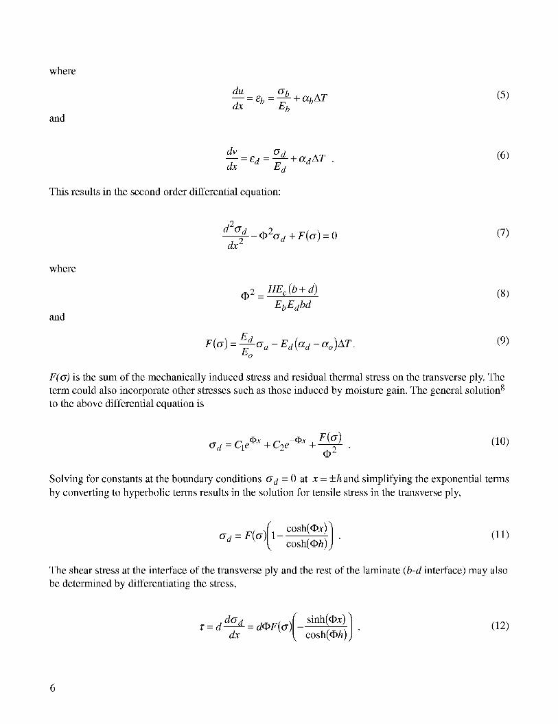
F(_) is the sum of the mechanically induced stress and residual thermal stress on the transverse ply. The
term could also incorporate other stresses such as those induced by moisture gain. The general solution 8
to the above differential equation is
F(o-) (lO)c_d = C1eox + C2 e-ox + 0------T-
Solving for constants at the boundary conditions o-d = 0 at x = +h and simplifying the exponential terms
by converting to hyperbolic terms results in the solution for tensile stress in the transverse ply,
cosh(Ox)] (11)G d = F(G) 1 cosh(Oh)) "
The shear stress at the interface of the transverse ply and the rest of the laminate (b-d interface) may also
be determined by differentiating the stress,
d dGd dOF(G)( sinh(Ox)]¢= dx = t-cosh(Oh))"
(12)
6

Based on the above equations, the stress distribution within the transverse ply can be plotted
as a function of distance between two microcracks. The tensile stress within the transverse ply
approaches the stress of the uncracked ply for large crack spacing. As the crack spacing decreases,
the transverse ply carries less tensile load (fig. 2). However, the shear stress is still present. Thus, diago-
nal cracks begin to appear due to the shear stress at higher crack densities. These diagonal cracks are
followed by delamination.
The strain energy can be used to predict the formation of microcracks. The Griffith energy
theory states
dW dU (13)AG-dA dA
where W is work, U is strain energy, and A is microcrack surface area. The change in work is the differ-
ence between work applied to the two cracked segments h after failure and the uncracked segment 2h
prior to fracture. The strain energy is determined in the same manor. The strain energy release rate can
be calculated as
AG = --H-- t_o-) 2tan(14)
Theoretically, cracking initiates when AG > Glc, where Glc is the critical strain energy release
rate. However, due to defects and statistical variations in the properties of the composite, cracking will
initiate at lower stresses than predicted. Thus, the first microcracks observed occur at strain energy
release rates lower than Glc. As the strain energy approaches Glc, the microcrack density will rise
rapidly. At higher microcrack densities, the transverse ply loses its ability to carry much tensile stress.
Thus, the rate of increase in microcracks per applied stress begins to diminish.
¢/1¢/1
.mm
Eo
Z
0.5
-0.5
-1
h_=5
s
h_=lO h_=2.5 h_=7.5
' i -- Tensile Stress' .... Shear Stress
Figure 2. Stresses within a cracked ply of a composite laminate with
various crack lengths (2h).
7

3.2 Composite Conformal, Cryogenic, Common Bulkhead, Aerogel-Insulated Tank
The microcracks in the CBAT laminate were not parallel to the fiber direction, +6 and -6 deg,
as is typical of a cross-ply laminate. The cracks were perpendicular to the loading direction. Thus, the
cracks periodically shift planes so the crack could penetrate both the +6 and the -6-deg plys (fig. 3). The
crack density increases slowly with increasing load. The initial cracks may be defect related as in figure
4. As the load is further increased, the slope of the crack density versus applied stress increases dramati-
cally. Eventually, as failure load is approached, the slope begins to decrease. This decrease in slope is
because the transverse ply carries less load and other failure modes are beginning to occur. Figures 5 and
6 illustrate the trend in crack density versus applied load for the CBAT laminate.
Y
x
Microcrack
Figure 3. Crack in CBAT laminate (x-y plane).
Figure 4. (a) First microcrack occurs on void and (b) failure occurs on the same void.
8

.m
,m
,=,
40
35
3O
25
2O
15
10
5
0
• -320 °F
tk 72 °F
J
Af..j..j .... &
ii • ( AA A A Ai i i i
0 10,000 20,000 30,000 40,000 50,000 60,000 70,000
i i
Stress(psi)
Figure 5. Crack density in (+6/-6)s ply of CBAT laminate versus
applied tensile load.
¢,J
,=,
40 •
35
3O
25
2O
15
10
5
0
.& 72 °F
• -320 °F
/"A
n i n--
10,000 20,000 30,000
_ n n n
40,000 50,000 60,000 70,000
Stress(psi)
Figure 6. Crack density in (+6/-6) ply of CBAT laminate versus
applied tensile load.
3.3 X-33 Liquid Hydrogen Tank
As with the CBAT laminate, a curve of microcrack density versus applied stress was produced.
Again, microcrack initiation was gradual. The density then increased rapidly with increasing stress
followed by a tapering of the slope prior to specimen failure.
The crack density versus applied load was calculated from equation (15). This was performed for
both longitudinal and hoop orientations at 72, -320, and -423 °F. The Glc for 72 °F was chosen to fit the
experimental data. From fracture mechanics,
G1 c _ _z°2 h (15)E
9

where Q is a geometry factor. If all other parameters are constant, strain energy release rate (G) is in-
versely proportional to modulus (E). Thus, as the modulus increases due to cooling, the strain energy
release rate decreases. The values used for Glc were 1.3, 0.9, and 0.8 in.-lb/in. 2 for 72, -320, and -
451 °F, respectively. These values are an order of magnitude lower than those reported by Nairn 2 and
one-half those reported by Fiberite. 1° These lower values warrant further examination. Figures 7 and 8
illustrate the trend in crack density versus applied load for X-33 laminate.
30
.E 25
20¢,J
e-a_
¢,J
5
Figure 7.
/ / ./J A o/< / // A @-423 F
/ (' / '& • -320 °F
,. • • • &A_A '_ A72oFi
i i i i
20,000 40,000 60,000 80,000 100,000
Stress(psi)
120,000
Crack density in hoop ply of X-33 laminate versus
applied tensile load.
30
.E 25
20
.-_ 15
al
" 10
5
/_" m / .J ....
./.- / A.---
/ /'/_
,/ /"/A Ai / / A_/
Ir A
i i
,*,-423 °F
• -320 °F
,&72 °F0 i
0 20,000 40,000 60,000 80,000 100,000 120,000
Figure 8.
Stress(psi)
Crack density in longitudinal ply of X-33 laminate versus
applied tensile load.
10

4. CONCLUSIONS
The shear lag/energy analysis modeled the crack density versus applied load quite well for the
X-33 tank inner skin. The method was less successful at modeling the CBAT laminate. The CBAT
laminate exhibited a higher crack density than predicted by the model. The model could more accurately
predict microcrack density by adjusting the constant (H).
The model will not predict crack initiation since the first cracks that appear are due to defects and
local variations in properties. A statistical approach should be used to model the initial cracking.
The modeling of crack density is highly dependent upon accurate elastic and thermoelastic
properties over the temperature ranges evaluated. One problem with the current model is that it does not
account for the temperature dependence of the CTE. The temperature dependence of the CTE makes the
residual stresses within the laminate subject to error. Another problem is that the model is based upon
uniaxial stress. A cryogenic tank, such as the X-33 tank, is subject to biaxial stress conditions. A lami-
nate that is tensile tested to the same hoop or longitudinal stress conditions of the tank will be subject to
different (generally higher) strains than the tank. Additional work is needed to further characterize the
IM7/977-2 at LH 2 temperatures.
11

REFERENCES
1. Goetz, R.C.; and Ryan, R.S., Co-Chairs; and Whitaker, A.E, Vice-Chair: "Final Report of the X-33
Liquid Hydrogen Tank Test Investigation Team," Marshall Space Flight Center, AL, May 2000.
. Nairn, J.A.; and Liu, S.: "The Formation and Propagation of Matrix Microcracks in Cross-Ply
Laminates During Static Loading," Journal of Reinforced Plastics and Composites, Vol. 2, pp. 158-
177, February 1992.
3. Nairn, J.A.: Polymer Matrix Composites, Talreja, R.; and Manson, J. A. (eds.): Chapter 13, "Matrix
Microcracking in Composites," 2000.
4. Garrett, K.W.; and Bailey, J.E.: "Multiple Transverse Fracture in 90-Degree Cross-Ply Laminates of
a Glass Fibre-Reinforced Polyester," Journal of Materials Science, Vol. 12, 1977, pp. 157-168.
5. Lee, J. W.; and Daniel, I.M.: "Progressive Transverse Cracking of Crossply Laminates," Journal of
Composite Materials, Vol. 24, pp. 1225-1243, November 1990.
6. Laws, N.; and Dvorak, G.J." "Progressive Transverse Cracking in Composite Laminates," Journal
of Composite Materials, Vol. 22, pp. 900-918, October 1988.
7. McManus, H.L.; and Maddocks, J.R.: "On Microcracking in Composite Laminates Under Thermal
and Mechanical Loading," Polymers and Polymer Composites, Vol. 4, No. 5, pp. 305-313, 1996.
8. Maddocks, J.R.; and McManus, H.L.: "Prediction of Microcracking in Composite Laminates Under
Thermomechanical Loading," NASA--CR-199800, January 1995.
9. CRC Standard Mathematical Tables, CRC Press, Inc., 1984.
10. Fiberite Data Sheet, 977-2 toughened epoxy resin, 1995.
12

REPORT DOCUMENTATION PAGE Form ApprovedOMBNo. 0704-0188
Public reporting burden for this collection of information is estimated to average 1 hour per response, including the time for reviewing instructions, searching existing data sources,gathering and maintaining the data needed, and completing and reviewing the collection of information. Send comments regarding this burden estimate or any other aspect of thiscollection of information, including suggestions for reducing this burden, to Washington Headquarters Services, Directorate for Information Operation and Reports, 1215 JeffersonDavis Highway, Suite 1204, Arlington, VA 22202-4302, and to the Office of Management and Budget, Paperwork Reduction Project (0704-0188), Washington, DC 20503
1. AGENCY USE ONLY (Leave Blank) 2. REPORT DATE 3. REPORT TYPE AND DATES COVERED
August 2001 Technical Memorandum4. TITLE AND SUBTITLE 5. FUNDING NUMBERS
Evaluation of Microcracking in Two Carbon-Fiber/Epoxy-Matrix
Composite Cryogenic Tanks
6. AUTHORS
A.J. Hodge
7. PERFORMING ORGANIZATION NAMES(S) AND ADDRESS(ES)
George C. Marshall Space Flight Center
Marshall Space Flight Center, AL 35812
9. SPONSORING/MONITORING AGENCY NAME(S) AND ADDRESS(ES)
National Aeronautics and Space Administration
Washington, DC 205464)001
8. PERFORMING ORGANIZATION
REPORT NUMBER
M 1024
10. SPONSORING/MONITORING
AGENCYREPORTNUMBER
NASA/TM 2001 211194
11. SUPPLEMENTARY NOTES
Prepared for Materials Processes and Manufacturing Department, Engineering D_ectorate
12a. DISTRIBUTION/AVAILABILITY STATEMENT
Unclassified-Unlimited
Subject Category 24Nonstandard Distribution
12b. DISTRIBUTION CODE
13. ABSTRACT (Maximum 200 words)
Two graphite/epoxy cryogenic pressure vessels were evaluated for microcracking. The X 33 LH2
tank lobe skins were extensively examined for microcracks. Specimens were removed from the
inner skin of the X 33 tank for tensile testing. The data obtained from these tests were used to
model expected microcrack density as a function of stress. Additionally, the laminate used in the
Marshall Space Flight Center (MSFC) Composite Conformal, Cryogenic, Common Bulkhead,
Aerogel-Insulated Tank (CBAT) was evaluated. Testing was performed in an attempt to predict
potential microcracking during testing of the CBAT.
14. SUBJECT TERMS
composite, microcrack, cryogenic tank, tensile testing
17. SECURITY CLASSIFICATIONOF REPORT
Unclassified
NSN 7540-01-280-5500
18. SECURITY CLASSIFICATIONOF THIS PAGE
Unclassified
15. NUMBER OF PAGES
2016. PRICE CODE
19. SECURITY CLASSIFICATION Z0. LIMITATION OF ABSTRACTOF ABSTRACT
Unclassified Unlimited
Standard Form 298 (Rev. 2-89)Prescribedby ANSI Std.239-18298-102