Evaluation of Marine VHF Radios: Performance in the · PDF fileNTIA REPORT 99-362 Evaluation...
26
NTIA REPORT 99-362 Evaluation of Marine VHF Radios: Performance in the Savannah, Ga. and New Orleans, La. Port Areas technical report U.S. DEPARTMENT OF COMMERCE National Telecommunications and Information Administration
-
Upload
dangnguyet -
Category
Documents
-
view
215 -
download
1
Transcript of Evaluation of Marine VHF Radios: Performance in the · PDF fileNTIA REPORT 99-362 Evaluation...
NTIA REPORT 99-362
Evaluation of Marine VHF Radios: Performance in the Savannah, Ga.
and New Orleans, La. Port Areas
technical reportU.S. DEPARTMENT OF COMMERCE é National Telecommunications and Information Administration

NTIA REPORT 99-362
Evaluation of Marine VHF Radios:Performance in the Savannah, Ga.
and New Orleans, La. Port Areas
Robert L. SoleBrent Bedford
U.S. DEPARTMENT OF COMMERCEWilliam Daley, Secretary
Larry Irving, Assistant Secretaryfor Communications and Information
March 1999


ii
EXECUTIVE SUMMARYThe maritime mobile frequency band supports maritime communications worldwide. Appendix 18
of the ITU Radio Regulations (RR) defines the channels of the maritime mobile service. These channelssupport a variety of communication functions including: public correspondence, intership, ship-to-coast,coast- to-ship, port operations, calling and various safety purposes. Safety functions include distress, searchand rescue, ship movement, navigation (bridge-to-bridge) communications, and maritime safety informationbroadcasts.
Mariners in the United States and other countries are experiencing interference on channelsallocated to the above functions. The Radio Technical Commission for Maritime Services (RTCM)established Special Committee 117 to investigate the interference and determine if the InternationalElectrotechnical (IEC) standard 1097-7 “Global Maritime Distress and Safety System (GMDSS)-Part7: Shipborne VHF Radiotelephone Transmitter and Receiver-Operational and PerformanceRequirements, Methods of Testing and Required Test Results” would be sufficient to protect marineVHF radios from interference. In support of this effort, NTIA, in coordination with the Coast Guard andRTCM SC-117, undertook a task to perform tests on commercial and recreational grade marine VHFradios to the IEC standard and perform radiated tests in areas where severe cases of interference areoccurring. Laboratory testing of the radios to the IEC standard was performed in Boulder, Colorado. Theradiated tests were performed in Savannah, Georgia on the Savannah River and on the Mississippi Riverin New Orleans, Louisiana Mariners in both locations have been reporting cases of severe interference inthe marine VHF band on the waterways for quite some time now. Some of the channels experiencing theinterference are key channels used for safety and bridge-to-bridge communications. The interference is verydisruptive to normal operations on the river and is distracting to the radio operators.
The IEC tests and radiated tests were based on receiver SINAD measurements. In the IEC 1097-7 test procedures, the SINAD of a receiver being tested was set to 20 dB by adjusting the desired signalpower and then injecting interference into the circuit to reduce the SINAD to 14 dB. The resultinginterference-to-signal ratio (I/S) was then calculated in dB and compared to the minimum IEC requirement.In the IEC tests, the interference was simulated using signal generators. The IEC tests simulated adjacentand co-channel interference, receiver saturation (blocking), and intermodulation interference. The radiatedtests used emitters that were present in the electromagnetic environment of the test area to degrade theSINAD. The radiated testing revealed that emitters in the environment were causing receiver saturation andintermodulation/cross modulation interference in the radio receivers.
Spectrum recordings were taken during the radiated tests when the SINAD measurements were14 dB or less. These recordings were used to identify the sources of interference in Savannah and NewOrleans. The recordings seem to indicate that the interference is due to NOAA weather broadcasts andland mobile transmitters ( 1997 Code of Federal Regulations, Parts 90 and 22 Title 47) operating withinand around the marine VHF band. The antennas of the weather broadcast and land mobile transmittersare located very close to the river’s edge in both locations and transmit at higher power levels than themobile marine VHF radios. Both of these factors contribute to the severity of the interference. However,it should be noted that the land mobile transmitters are operating in compliance with respect to the FCCrules and regulations for output power, frequency tolerance, and spurious emissions. The NOAA VHFweather broadcasts also seem to be operating properly.

iii
Because they are operating in compliance with the FCC rules and regulations, it would be difficultto impose any operating restrictions on land mobile systems operators. Therefore practical solutions tosolve this problem would be to continue the development of receiver standards through RTCM SC-117,encourage mariners to use radios that are more resistant to interference, and develop antenna sitingguidelines for future deployment of weather broadcast and land mobile transmitters to reduce interference.

iv
TABLE of CONTENTS
Section 1. Introduction 1.1 Background . . . . . . . . . . . . . . . . . . . . . . . . . . . . . . . . . . . . . . . . . . . . . . . . . . . . . . . 1-1 1.2 Test Objectives . . . . . . . . . . . . . . . . . . . . . . . . . . . . . . . . . . . . . . . . . . . . . . 1-2 1.3 Test Radios . . . . . . . . . . . . . . . . . . . . . . . . . . . . . . . . . . . . . . . . . . . . . . . . . . . . . . . 1-2
Section 2. Test Results 2.1 Savannah, Georgia Tests . . . . . . . . . . . . . . . . . . . . . . . . . . . . . . . . . . . . . . . . . . . . 2-1 2.2 New Orleans, Louisiana Tests . . . . . . . . . . . . . . . . . . . . . . . . . . . . . . . . . 2-6 Section 3. Interference Coupling Mechanisms . . . . . . . . . . . . . . . . . . . . . . . . . . 3-1 3.1 Blocking and Receiver Front-end Overload/Saturation . . . . . . . . . . . . . 3-1 3.2 Intermodulation and/or Cross-modulation . . . . . . . . . . . . . . . . . . . . . . . . . . . . . 3-2 3.2 RTCM Receiver Standard . . . . . . . . . . . . . . . . . . . . . . . . . . . . . . . . . . . . . . . . . . . 3-3
Section 4 Evaluation of Radio Performance. . . . . . . . . . . . . . . . . . . . . . . . . . . . . . . . . . . 4-1
Section 5. Conclusions and Recommendations . . . . . . . . . . . . . . . . . . . . . . . . . . 6-1
Appendix A: Radiated Test Procedures . . . . . . . . . . . . . . . . . . . . . . . . . . . . . . . . . . . . . . A-1
Appendix B: Savannah SINAD Histographs . . . . . . . . . . . . . . . . . . . . . . . . . . . . . B-1
Appendix C: New Orleans SINAD Histographs . . . . . . . . . . . . . . . . . . . . . . . . . . . . . . . . C-1

1-1
SECTION 1INTRODUCTION
1.1 BackgroundNTIA published a report for the Coast Guard that studied the compatibility between 12.5 kHz and
25 kHz channelized marine VHF radios, NTIA TR-97-343 “Assessment of Compatibility between 25and 12.5 kHz Channelized Marine Radios.” One of the conclusions of the report was that the adoptionof appropriate standards for marine VHF radio receivers would help alleviate problems due to congestionin the marine electromagnetic environment. Currently, the United States does not have receiver standardsfor marine VHF radios. An organization comprised of mariners, radio manufacturers, and frequencyregulators, the Radio Technical Commission for Maritime services (RTCM), established RTCM SC-117to investigate receiver standards developed by other regulatory agencies or organizations. One organization,the International Electrotechnical Commission (IEC), has recently published a document that containsproposed standards for marine VHF radios.
The IEC standards for marine radios are in a document titled “IEC 1097-7: Global MaritimeDistress and Safety System (GMDSS)-Part 7: Shipborne VHF Radiotelephone Transmitter andReceiver-Operational and Performance Requirements, Methods of Testing and Required TestResults”.
In support of this effort, NTIA, in coordination with the Coast Guard and RTCM SC-117,undertook a task to perform tests on commercial and recreational grade marine VHF radios to the IECstandard and perform radiated tests in areas where severe cases of interference are occurring. This taskwas accomplished by testing marine VHF radios in a laboratory to the IEC 1097-7 standard and thentesting those same radios in marine environments where mariners have reported severe cases ofinterference. Savannah, Georgia and New Orleans, Louisiana were chosen as locations for “live” testingdue to the numerous complaints from mariners that their communications are being disrupted on theSavannah and Mississippi Rivers due to interference in the marine VHF band.
The IEC procedures and standards are based on receiver SINAD measurements and signal-to-interference (S/I) ratios. A receiver SINAD measurement is the ratio, expressed in dB, of the desired signalpower to interference, noise, and distortion. The methodology of the IEC laboratory tests was to measurethe receiver SINAD with interference injected into the radio along with the desired signal. Each test hada minimum performance objective for the SINAD and signal-to-interference (S/I) ratio in the presence ofinterfering signals. The laboratory tests used signal generators as interference sources to degrade thereceiver SINAD measurements. The tests performed in Savannah and New Orleans used emitters thatwere present in the electromagnetic environment to degrade the receiver SINAD measurement. This reportdocuments the results of performing SINAD tests on marine VHF radios in the Savannah, Georgia andNew Orleans, Louisiana port areas and how the results relate to the laboratory tests. This report alsoattempts to identify the interference coupling mechanisms and ways to mitigate their effects. The results ofthe laboratory tests conducted to the IEC 1097 standard, which contains the recorded data for each radiotested are published in NTIA Report 99-363.
1-2
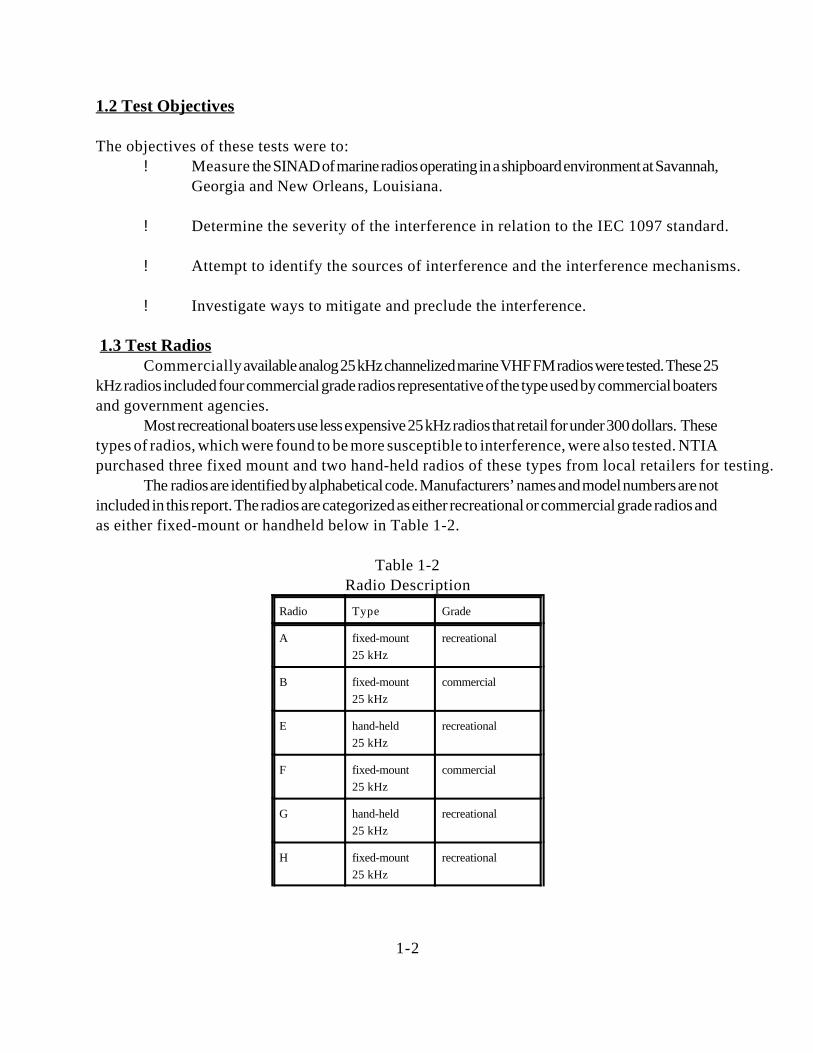
1.2 Test Objectives
The objectives of these tests were to:! Measure the SINAD of marine radios operating in a shipboard environment at Savannah,
Georgia and New Orleans, Louisiana.
! Determine the severity of the interference in relation to the IEC 1097 standard.
! Attempt to identify the sources of interference and the interference mechanisms.
! Investigate ways to mitigate and preclude the interference.
1.3 Test RadiosCommercially available analog 25 kHz channelized marine VHF FM radios were tested. These 25
kHz radios included four commercial grade radios representative of the type used by commercial boatersand government agencies.
Most recreational boaters use less expensive 25 kHz radios that retail for under 300 dollars. Thesetypes of radios, which were found to be more susceptible to interference, were also tested. NTIApurchased three fixed mount and two hand-held radios of these types from local retailers for testing.
The radios are identified by alphabetical code. Manufacturers’ names and model numbers are notincluded in this report. The radios are categorized as either recreational or commercial grade radios andas either fixed-mount or handheld below in Table 1-2.
Table 1-2Radio Description
Radio Type Grade
A fixed-mount25 kHz
recreational
B fixed-mount25 kHz
commercial
E hand-held25 kHz
recreational
F fixed-mount25 kHz
commercial
G hand-held25 kHz
recreational
H fixed-mount25 kHz
recreational

1-3
I fixed-mount25 kHz
recreational
K fixed-mount25 kHz
recreational
L fixed-mount25 kHz
commercial
M fixed-mount25 kHz
commercial
Radio L had a local/distance switch for its receiver accessible on a front panel control which wasseparate from the squelch control. Radio M had an adjustable attenuator for its receiver which was partof the squelch control. These radios were designed with these features for operations in congested EMenvironments.

2-1
SECTION 2TEST RESULTS
2.1 Savannah, Georgia The test area for Savannah is shown below in Figure 2-1. The radios were tested using the
procedures outlined in Appendix A with the test set-up shown in Figure A-1.
Figure 2-1Savannah Test Area
The performance of the radios was evaluated on channel 18A (156.900 MHz) during normaltugboat operations by monitoring the test radios SINAD measurements. This channel is used by a localtugboat company as a primary communications link between their dispatch office and the tugboat fleet. Theinterference on this channel is very disruptive to their business operations and distracting to radio operators.Other marine channels are affected by the interference in this area as well, including channels 16 and 13.The test set-up was installed in the wheelhouse of one of the tugboats and data was collected as the tugboattraveled on the river or was stationary. The test area is identified in Figure 2-1 as the stretch of theSavannah River between the points labeled the East Dock and the West Dock. The tugboat dispatch officeis also shown in Figure 2-1.
For a baseline configuration, the SINAD of the radio under was set to 20 dB by adjusting the RFpower of the signal generator with a load connected into the circuit in place of the antenna (see Fig. A-1).When the load was removed and the tugboat antenna was connected into the circuit, the receiver of theradio being tested immediately experienced de-sensitization and periodic audible interference was heard
2-2
in the radio receiver. The de-sensitization was observed by watching the degradation of the receiverSINAD as measured by the test set. Depending on the radio under test, the SINAD was immediatelydegraded from the 20 dB starting point to approximately 2-14 dB when the tugboat antenna was connectedinto the circuit. The audible interference further degraded the SINAD to 0-4 and was periodic in nature.
The receiver de-sensitization was not audible in the receivers. Except for radio L operating in localmode, the periodic audible interference occurred in all radios and rendered the channel useless forcommunications during the period that it occurred. The duration of the audible interference events wasapproximately 3.5-4 seconds. Multiple consecutive events compounded the problem.
A SINAD histogram for each radio tested is shown in Appendix B. The histograms show thepercent of time versus SINAD value and includes all SINAD values, not just those below 14 dB. This levelis the minimum allowable SINAD value with interference present in the IEC 1097-7 test procedures.Radios that had a higher percentage of time with a greater SINAD value had better performance. Thiseffect is shown in Figures B-1 and B-2. Figure B-1 shows the SINAD histogram for radio L in thedistance mode and Figure B-2 is the same radio operating in local mode. In the distance mode, the SINADvalues ranged from 1-13 dB with the major portion of the distribution in the 7-10 dB range. In the localmode the SINAD values ranged from 7-19 dB with the major portion of the distribution in the 10-15 dBrange. The differences between the figures show that for the overall percentages of time, the local modeof operation measured higher SINAD values than distance mode and the radio had audibly betterperformance. However, for local mode operation the radio requires a minimum desired signal power ofabout -107 dBm versus -117 dBm for distance mode for a 20 dB SINAD.
Some of the less costly recreational grade radios were essentially “flatlined” by the desensitizationand audible interference. For example, the SINAD for radio E in Figure B-9 never got above 3 dB. Otherrecreational grade radios never had a SINAD above 5 dB. These types of radios are used for commercialand non-commercial marine communications.
In an attempt to identify the sources of interference, a spectrum analyzer was used to sweep the150-174 MHz band and record the power of the emitters when the SINAD of the radio under test fellbelow 14 dB. The receiver de-sensitization effect and the audible interference caused the SINAD to bebelow the trigger point so that data was collected for each type of interference event. With the exceptionof the hand held radios, data was collected for each radio during tugboat operations. Data was collectedfor the hand held radios at the tugboat office located at the river’s edge.
Since the radios were tested in the same environment and experienced the same type ofinterference, the spectrum record taken for an interference event for any one radio is typical for all radiostested. However, in some cases of interference events, different emitters were observed to be active atdifferent times.
The spectrum recordings shown below in Figures 2-2, 2-3, 2-4, and 2-5 were recorded whiletesting radio L, tuned to channel 18A (156.9 MHz), on the tugboat. These figures only show emitters thatwere transmitting at that instant that this particular spectrum snapshot was taken. Other spectrum snapshotsmay show different emitters active at different frequencies other than those shown in Figures 2-2 to 2-5.Figure 2-2 shows a spectrum record for the 150-164 MHz band. Figures 2-3, 2-4, and 2-5 showportions of that band in greater detail to help identify individual emitters.

2-3
-100
-80
-60
-40
-20
0
Rec
eive
d p
ow
er (
dB
m)
151 153 155 157 159 161 163 Frequency (MHz)
Radio L, Distance ModeCh 18A, 1.5 dB Sinad
-90
-80
-70
-60
-50
-40
-30
Rec
eive
d p
ow
er (d
Bm
)
152 153 154 Frequency (MHz)
Radio L, Distance ModeCh 18A, 1.5 dB Sinad
Figure 2-2151-164 MHz Band Spectrum Record
This spectrum trace was recorded when the audible interference reduced the SINAD of receiverL to 1.5 dB. The signals shown below in Figure 2-3 are transmitters operating at the following frequencies:152.24, 152.48, and 152.84 MHz. Their operations were periodic and peaked in the morning andevening.
.
Figure 2-3152-154 MHz Band Spectrum Record
. The signals shown below in Figure 2-4 are transmitters operating at 158.7 and 158.925 MHz.
Their operations were periodic and peaked in the morning and evening.

2-4
-90
-80
-70
-60
-50
-40
-30
Rec
eive
d p
ow
er (d
Bm
)
158 159 160
Frequency (MHz)
Radio L, Distance ModeCh 18A, 1.5 dB Sinad
-100
-80
-60
-40
-20
0
Rec
eive
d po
wer
(dB
m)
162 163 164 Frequency (MHz)
Radio L, Distance ModeCh 18A, 1.5 dB Sinad
Figure 2-4158-160 MHz Band Spectrum Record
Figure 2-5162-164 MHz Band Spectrum Record
The signal shown in Figure 2-5 is identified as a NOAA weather transmitter broadcasting at 162.4MHz. This transmitter is also identified as WX2 in the VHF marine weather channel assignments. Thistransmitter was “on” at all times and not periodic like some of the emitters in the previous figures. The figureshows the received power to be approximately -10 dBm. This signal and its interference mechanism wasvery similar to the IEC “blocking” test, which was shown to saturate the radio receivers at such a highpower level.
The land mobile transmitters identified in Figures 2-3 and 2-4 produced received power levels upto -27 dBm at the radio receiver. These power levels were shown to produce intermodulation productsin some receivers in the IEC intermodulation bench test.

2-5
At the tugboat dispatch office, additional tests were performed by using RF step attenuators todecrease the interferer powers till the audible periodic interference was no longer heard in the radioreceiver. This test was performed aurally and did not involve a SINAD measurement. The amount ofattenuation each radio needed to effectively eliminate the audible interference is shown below in Table 2-1.
Table 2-1Receiver Attenuation Values
Radio Receiver Attenuation (dB)
B 10
F 10
G 20
H 10
I 30
K 20
As shown in Table 2-1, the range of attenuation needed to lower the power of the land mobiletransmitters and weather channel emissions into the radio receiver to reduce the audible interference so thatthe 1 kHz test tone was audible ranged from 10 to 30 dB. The attenuation also reduced the sensitivity ofthe radio. The resolution for these tests was 10 dB. It was difficult to “hear” the change in the level of theaudible interference using smaller steps of attenuation.

2-6
2.2 New Orleans, LouisianaThe test area for New Orleans is shown below in Figure 2-6. The radios were tested using the
procedures outlined in Appendix A.
Figure 2-6New Orleans Test Area
The SINAD performance of the radios was evaluated on marine VHF channels 25 (publiccorrespondence receive, 161.850 MHz) and 67 (bridge-to-bridge, 156.375 MHz). The test set-up wasinstalled in a fire boat and data was collected as the boat traveled the river or was docked. The radioswere tested using channel 25 as the desired signal channel while docked at location 1 shown in Figure 2-7.The radios were tested using channel 67 as the desired signal channel while docked at location 2 shownin Figure 2-6. Channel 67 is the primary channel for bridge-to-bridge communications on the lowerMississippi River. Mariners have complained about the interference on this channel for quite some time.Interference on this channel can make communications difficult between ships on the river. The interferenceon channel 67 seemed to be “worst” in the river main channel. However, due to the large amount of trafficin the river channel it was not safe to loiter in the channel itself and collect data while testing multiple radios.
At both test locations, the radios experienced receiver de-sensitization and periodic audibleinterference was heard in the radio receiver. The de-sensitization was observed by watching thedegradation of the receiver SINAD as measured by the communication test set. Depending on the radio

2-7
being tested, the SINAD was reduced from the 20 dB starting point to approximately 2-15 dB when theship’s antenna was connected into the circuit. The periodic audible interference further reduced the SINADto approximately 1-5 dB.
The receiver de-sensitization was not audible on the receivers. Except for radio L operating in localmode and radio M with the built in attenuator set at its maximum value, the periodic audible interferenceoccurred in all radios and rendered the channel useless for communications during that period. The durationof the audible interference events was approximately 3.5-4 seconds. Multiple consecutive eventscompounded the problem..
A SINAD histogram for each radio tested in New Orleans is shown in Appendix C. As shownin Savannah, radios that had a higher percentage of time with greater SINAD values had betterperformance. This effect is once again shown for radio L in Figures C-1 and C-2. Figure C-1 shows theSINAD histogram for radio L in distance mode and Figure C-2 is radio L in local mode operation. Indistance mode the SINAD values ranged from 1-8 dB with the major portion of the distribution in the 2-4dB range. In the local mode the SINAD values ranged from 14-19 dB with the major portion of thedistribution in the 14-17 dB range. The differences between the figures show that for the overallpercentages of time, the local mode of operation measured higher SINAD values than distance mode andthe radio had audibly better performance. As in the case of Savannah, the SINAD measurements of therecreational grade radios in New Orleans was in the 0-5 dB range and the 1 kHz test tone was inaudibledue to the interference.
A spectrum analyzer was used to sweep 150-174 MHz band and record the power of the emitterswhen the SINAD of the radio under test was 14 dB or less. These spectrum recordings showed that theEM environment of New Orleans was denser than Savannah with more emitters present. The receiver de-sensitization effect and the audible interference caused the SINAD to be below the trigger point so that datawas collected for each type of interference event. The dense EM environment made it difficult to identifyspecific emitters during the audible interference.
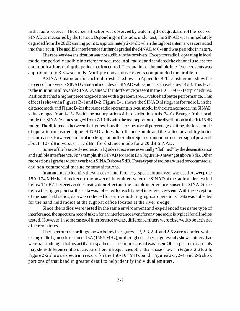
Sample spectrum plots are shown below in Figures 2-7 to 2-9 They were taken during the testingof radio L at location one. These plots are representative of the EM environment at that instant that thisparticular SINAD measurement was taken. They should not be considered to be indicative for all casesof interference events.
2-8
-100
-80
-60
-40
-20
0
Rec
eive
d P
ower
, dB
m
151 152 153 154 155 156 157 158 159 160 161 162 163
Frequency, MHz
New OrleansSpectrum Plot
-100
-80
-60
-40
-20
0
Rec
eive
d P
ower
, dB
m
151 152 153 154 155
Frequency, MHz
New OrleansSpectrum Plot
Figure 2-7151-163.5MHz Band
Figure 2-8151-156 MHz Band
2-9
-100
-80
-60
-40
-20
0
Rec
eive
d P
ower
, dB
m
157 158 159 160 161 162 163
Frequency, MHz
New OrleansSpectrum Plot
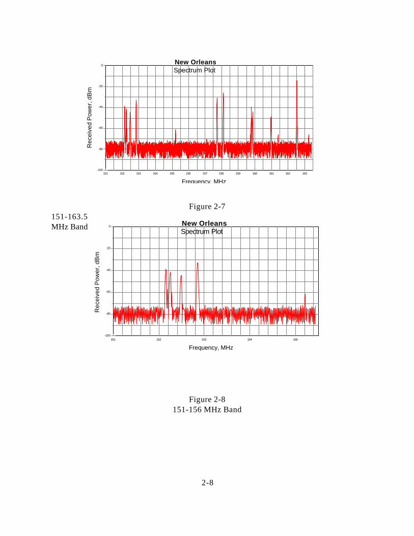
Figure 2-9157-163.5 MHz Band
The figures show numerous maritime and land mobile emitters in this band in New Orleans. Thetransmitter that produced the highest received power on the fireboat in New Orleans was weather channelWX1 at 162.55 MHz. The received power at the radio RF input jack from this transmitter wasapproximately -15 dBm. The IEC blocking tests showed that this power level would saturate the radioreceivers. The power level fluctuated as the ship traversed the river due to shielding from the downtownbuildings and bridges. This would explain why some spots on the river are more prone to interference thanothers.
Additional tests were performed by using the RF step attenuators to decrease the power of theinterferers till the audible periodic interference was no longer heard in the radio receiver. This test wasperformed aurally and did not involve a SINAD measurement. The amount of attenuation each radioneeded to effectively eliminate the audible interference is shown below in Table 2-2.
Table 2-2Receiver Attenuation Values
Radio Receiver Attenuation (dB)
B 20
E 20
F 10
G 30
H 10
I 30

2-10
K 20
M 10
As shown in Table 2-2, the range of attenuation needed to lower the power of the land mobiletransmitters and weather channel emissions into the radio receiver to reduce the audible interference so thatthe 1 kHz test tone was audible ranged from 10 to 30 dB. The attenuation also reduced the sensitivity ofthe radio. The resolution for these tests was 10 dB. It was difficult to “hear” the change in the level of theaudible interference using smaller steps of attenuation..
3-1
SECTION 3INTERFERENCE COUPLING MECHANISMS
3. Blocking and Receiver Front-end Overload/SaturationThe receiver front-end overload/saturation and subsequent SINAD reduction at both Savannah
and New Orleans would seem to be due to proximity of NOAA VHF weather broadcast transmitters tomariners on the Savannah and Mississippi rivers. At Savannah the NOAA weather station broadcasts at162.4 MHz and is identified as WX2. The antenna used by this weather broadcast station is located on topof a 10 story building located under half a mile from the river’s edge near the tugboat company dispatchoffice. During testing, the distance from the weather broadcast antenna to the tugboat ranged from one-halfto five miles. The highest the received power of the weather station as measured at the input of each radiowas approximately -10 dBm..
The tugboat company dispatch office had two antennas mounted on a tower that wasapproximately 100 feet high for their base station radio operations. One antenna was mounted about 50feet up the tower and the other was mounted close to the top. The radio in the dispatch office did notexperience audible interference and had a good SINAD measurement when connected to the lowerantenna. When connected to the top antenna the dispatch radio experienced interference similar to that ofthe radio tested on the tugboat in the river. Visual inspection of the geometry between the lower antennaon the dispatch tower and weather antenna on the bank building showed that the weather signal wasdiffracting over the edge of an adjacent building that was taller than the lower antenna. This signal diffractionlowered the received power of the weather broadcast by about 20-30 dB over the top antenna and almosteliminated the interference in the dispatch office radio. This effect clearly demonstrated that the weatherbroadcast was partly to blame for the interference in some radios. Other test radios were also tested in thismanner with the same result. In New Orleans the NOAA weather station broadcasts at 162.55 MHz and is identified as WX1.The antenna used by this weather broadcast station is located on top of a 20 story building located abouthalf a mile from the river’s edge. During testing, the distance from the weather broadcast antenna to the fireboat ranged from about half a mile at location one to under two miles at location two. The highest thereceived power of the weather station as measured at the input of each radio was approximately -15dBm.. The weather broadcasts were continuously on during the testing. The received power level changedas the boat moved in the river due to shielding and diffraction.
The IEC specification for blocking is -23 dBm at the radio RF input, which would result in aminimum SINAD of 14 dB. In Savannah the received power of the NOAA signal, which resembles theunwanted signal in the IEC blocking test, was 13 dB above the specification. In New Orleans the receivedpower of the NOAA signal was 8 dB above the specification.
Some RF filtering in the front end of marine radios might be expected because the desired signalchannels and the weather broadcasts were separated by at least 700 kHz or more. However, the marineradios that were tested were designed to receive all VHF marine weather broadcast channels and thereforedo not have any RF rejection to NOAA weather broadcasts. In addition, the marine VHF radio receiversalso do not have any RF rejection to land mobile transmitters operating within the band.
Receiver front-end overload/saturation may not be audible or apparent to the radio operators. The
3-2
weather broadcasts were audible in only one of the radio receivers while it was tuned to a desired testchannel. Non-audible interference would cause a reduction in the reception range for the radio receiverand would not be obvious to the radio operator. For example, if the radio operator was unable to discerna weak signal in the presence of the weather broadcasts or any other strong in-band signal, they might saythat the radio had gone “deaf”. The radio operator would not be able to hear the person that they weretrying to communicate with, but also would not hear any interference coming through the radio receiver.Hence, the radio was quiet and had gone “deaf”.
3.2 Intermodulation and/or Cross-modulationIn addition to maritime communications, the VHF maritime mobile band is used by land mobile
systems for a variety of functions. The functions and the frequencies that these land mobile systems operateon are listed in Parts 22 (Public Mobile Service) and 90 (Private Land Mobile Radio Services ) of theCode of Federal Regulations (CFR). The spectrum recordings that were taken in Savannah and NewOrleans showed that numerous land mobile systems that operate according to these parts of the CFR wereactive in both areas.
In Savannah and New Orleans, the audible intermodulation interference in the radio receiversseems to be attributable to land mobile transmitters and the NOAA VHF weather broadcasts. The landmobile transmitters and the weather broadcasts were identified as possible sources of interference bylistening to the interference and observing the display on the spectrum analyzer. However, the interferencemechanism may be a combination of intermodulation and/or cross modulation products. An intermodulationproduct is due to two or more signals driving the radio receiver circuitry into non-linear operation. Crossmodulation is the result of an interfering signal that is strong enough to act as a local oscillator in the radioreceiver.
The land mobile transmitters seemed to initiate the audible interference events. This was observedby listening to the radio and watching the spectrum analyzer’s display. The audible interference onlyoccurred when the land mobile transmitters were active. During the audible interference events, receiveraddressing tones could be heard followed by land mobile data transmissions. During the land mobiletransmissions the weather broadcast could also be heard as somewhat garbled but identifiable voiceinterference in the radio receiver.
Previous studies done by the FCC have shown that when WX2 is not broadcasting in Savannah,the audible interference does not occur (this test was not performed by NTIA). According to the FCC theWX2 weather broadcast has been transmitting from the same antenna location for over 10 years andcomplaints from mariners about the interference only started to be reported in the past few years as landmobile systems were deployed in the area. During our tests, WX2 was continuously transmitting and theaudible interference only occurred when the land mobile transmitters became active. The results of thesetests show that the combination of land mobile transmitters and weather broadcasts in the same EMenvironment can generate interference in marine VHF radio receivers.
Personnel from the FCC Compliance Bureau field office based in New Orleans have investigatedthe reports of interference in Savannah and New Orleans and stated that the land mobile systems andNOAA weather broadcasts in Savannah and New Orleans are operating within Federal guidelines withrespect to output power, signal deviation, and spurious emissions
3-3
Although land mobile transmitters have been identified as a component of the audible interference,determining which land mobile transmitters are causing the interference on specific marine channels isdifficult. Inspections of the spectrum recordings show that numerous land mobile transmitters were activewhen these recordings were made and the interference was present. With so many land mobile transmittersactive when the interference was heard, it was difficult to determine just exactly which ones werecontributing to the interference on the desired test channels. The received power levels of the landmobile transmitters at the radios RF input were greater than the unwanted signal power levels that wereused in the IEC intermodulation rejection ratio test. The received power levels of the land mobiletransmitters was up to -27 dBm at the radios RF input and generated intermodulation interference in allreceivers except radio M and radio L operating in local mode. Testing the radios in the laboratory to theIEC intermodulation rejection ratio procedures revealed that unwanted signal powers ranging from -55 to-34 dBm were sufficient to generate the intermodulation interference and lower the SINAD to 14 dB. Theonly radio which had laboratory test values equal to the land mobile received power levels was radio Loperating in local mode. Radio was not available for testing when the laboratory test were performed.
3.3 RTCM RECEIVER STANDARDRTCM has developed a draft receiver standard for marine VHF radios that is based on the
received powers of the land mobile and NOAA transmitters that were measured at the RF input of the testradios. The standard is a combination of blocking and intermodulation rejection ratio tests which are similarto tests and procedures outlined in IEC 1097. The major difference between the RTCM test and the IECtests is that the unwanted signal powers in the RTCM standard are set at specific levels while the IEC testsare referenced to the receivers maximum usable sensitivity. In the RTCM standard, the blocking signal isset at -15 dBm at the receiver input and the two unwanted signals that simulate the land mobile transmittersare set at -27 dBm. The RTCM performance requirement is that the receiver have a minimum SINAD of14 dB with a wanted signal power of -107 dBm at the receiver RF input and the afore mentionedunwanted signals also being present.

4-1
SECTION 4EVALUATION of RADIO PERFORMANCE
The performance of the radios was evaluated using the SINAD histograms and by listening to theradio during the tests. Radios that had histograms which showed a distribution of SINAD measurementsto higher values for a greater percentage of time performed better than those radios that had low SINADvalues for higher percentages of time. Some radios performed better in Savannah than New Orleans.
A brief discussion of each radio’s histograms from the New Orleans and Savannah tests is givenin the following paragraphs.
Radio ARadio A is a recreational grade fixed mount radio. The histogram for this radio (Figure B-7) shows
that this radio receiver never had a SINAD above 4 dB and that most of the SINAD distribution was inthe 1-3 dB range. The radio was in a constant state of saturation and the 1 kHz test tone was almostinaudible due to the intermodulation interference. This was the only radio in which the weather broadcastcould be heard when the radio was tuned to the test channel. The radio broke and was not tested in NewOrleans. This radio performed poorly.
Radio BRadio B is a commercial grade fixed mount radio. The histogram for this radio (Figure B-6 and
Figure C-4) shows that in Savannah the radio had a SINAD distribution of 0-13 dB while in New Orleansthe values were never above 4 dB.
Radio ERadio E is a recreational grade handheld radio. The histograms for this radio (Figures B-9 and C-
10) show that this radio never had SINAD measurements above 4 dB and that most of the distribution wasin the 0-3 dB range. This radio had a plastic housing and case penetration may have added to its poorperformance.
Radio FRadio F is a commercial grade fixed mount radio. The histograms for this radio (Figures B-3 and
C-7) show SINAD measurements from 3-14 dB in Savannah and 1-13 dB in New Orleans. This radioseemed to function well in Savannah but was more degraded in New Orleans. It had better performancethan the recreational grade radios but not as good performance as the other commercial grade radios.
Radio GRadio G is a recreational grade handheld radio. The histograms for this radio (Figures B-10 and
C-9) shows that this radio receiver had SINAD measurements from 1-5 dB and that most of the SINADdistribution was in the 1-3 dB range. The radio was in a constant state of saturation and the
4-2
1 kHz test tone was almost inaudible due to the intermodulation interference. This radio performed poorly.
Radio HRadio H is a recreational grade fixed mount radio. The histograms for this radio (Figures B-3 and
C-3) show that this radio receiver had SINAD measurements from 1-14 dB and that most of the SINADdistribution was in the 6-12 dB range. This radio seemed to work better in Savannah than New Orleans.For a recreational grade radio it had moderate performance.
Radio IRadio I is a recreational grade fixed mount radio. The histograms for this radio (Figure B-5 and
C-6) show that this radio receiver never had a SINAD above 5 dB and that most of the SINADdistribution was in the 1-3 dB range. The radio was in a constant state of saturation and the 1 kHz test tonewas inaudible due to the intermodulation interference. This radio had an unshielded plastic housing and casepenetration interference was possibly occurring. This radio performed terribly.
Radio KRadio K is a recreational grade fixed mount radio. The histograms for this radio (Figures B-8 and
C-8) show that this radio receiver never had a SINAD above 7 dB and that most of the SINADdistribution was in the 1-5 dB range. The radio was in a constant state of saturation and the 1 kHz test tonewas almost inaudible due to the intermodulation interference. This radio performed poorly.
Radio LRadio L is a commercial grade fixed mount radio that incorporates a local/distance switch in its
receiver that is accessible from the front panel of the radio. The histograms for this radio (Figures B-1, B-2and C-1 and C-2) show that in distance mode (Figures C-1 and B-1) this radio receiver had SINADmeasurements from 1-14 and in local mode had measurements from 8-18 dB. Using the local mode settingon the radio receiver removed almost all of the audible interference. This radio performed well in localmode and had marginal performance in distance mode.
Radio MRadio M is a commercial grade fixed mount radio. The histograms for this radio (Figure C-5)
shows that this radio receiver SINAD values from 1-14 dB. This radio had an externally adjustableattenuator for operations in harsh EM environments that was also connected to the radio’s squelch control.Although the radio was able to operate in New Orleans when the attenuator was set to its full value, thesquelch closed and about 3 dB more of desired signal power was needed to restore the SINAD. The radiowas not in the test inventory for the Savannah tests. This radio worked well.

5-1
SECTION 5CONCLUSIONS and RECOMMENDATIONS
5. Conclusions The following conclusions can be drawn from these tests:
1. VHF FM marine radios are experiencing receiver saturation and intermodulation/crossmodulation interference on numerous channels at Savannah, Georgia and New Orleans, Louisiana, includingthose used for key ship-to-ship and safety communications.
2. The received power levels of the land mobile emitters in New Orleans and Savannah at theradios RF input was up to -27 dBm, which exceed the levels of simulated interference set by the IEC 1097intermodulation test by up to 28 dB.
3. The received power levels of the NOAA VHF weather broadcats in New Orleans andSavannah at the radios RF input was up to -10 dBm, which exceed the levels of simulated interference setby the IEC 1097 blocking test by up to 19 dB.
4.The receiver saturation and intermodulation/cross modulation interference appears to beattributable to CFR Title 47 Parts 22 and 90 land mobile operations in the marine VHF band and NOAAVHF weather broadcasts.
5. The marine VHF radios do not have any protection against land mobile operations and weatherbroadcasts that operate within its receiver passband.
6. NOAA weather radio and land mobile transmitter antennas are very close to the river’s edgein Savannah and New Orleans resulting in higher received unwanted signal powers at the marine radios RFinput, which further exacerbates the interference problems.
7. The FCC Compliance and Information Bureau field office in New Orleans has stated that theland mobile systems in Savannah and New Orleans are operating within CFR Parts 22 AND 90 Title 47guidelines with respect to output power, signal deviation, and spurious emissions.
8. Some high quality commercial grade radios have an internal attenuator selectable with alocal/distance switch or squelch control that reduces the sensitivity of the radio receiver. Such radios werecapable of operating satisfactorily in the New Orleans and Savannah electromagnetic environment.
8. Recreational grade radios were able to overcome the interference with an external attenuatorat the receiver RF input which ranged in values from 10 to 30 dB. The sensitivity of the radio was alsodegraded by the attenuation.

5-2
9. The RTCM SC-117 draft receiver standard for marine VHF radios, which is based oninterference power levels that were recorded in New Orleans and Savannah, should be sufficient to protectmarine radio receivers from saturation and intermodulation interference.
5.1 RecommendationsIt is recommended that the Coast Guard consider the following items in resolving reports of interferencein marine VHF radios at US ports and waterways:
1. In the interests of increased public safety and environmental concerns for maritime operationson rivers, lakes, inland waterways, and coastal areas of the United States, the Coast Guard district officesshould inform mariners which radios are commercially available that can function at Savannah and NewOrleans when complaints of interference are sent to their offices.
2. Promoting the RTCM SC-117 receiver standard among different manufacturers so that moreradios are available at an affordable price to the general boating public which can meet the standard.
3. To reduce interference from occurring in marine VHF radio receivers from future deploymentsof NOAA VHF weather broadcasts near ports and waterways, working with NOAA to develop antennasiting guidelines for NOAA VHF weather transmitters. These guidelines could possibly be incorporatedin the NTIA manual. The guidelines should be based on marine radio performance that is in accordancewith the RTCM receiver standard.
4. To reduce interference from occurring in marine VHF radio receivers from future operations ofland mobile systems in the VHF band, working with the FCC and NTIA in developing antenna sitingguidelines for land mobile transmitters that can be incorporated in the Code of Federal Regulations. Theguidelines should be based on marine radio performance that is in accordance with the RTCM SC-117receiver standard.