Evaluation of Hyperstacking method for GPR surveys
6
SAGEEP 2016 Denver, Colorado USA http://www.eegs.org EVALUATING THE EFFECTIVENESS OF HYPERSTACKING FOR GPR SURVEYS Dr. Jeffrey Feigin, GSSI, Nashua, NH Dr. David Cist, GSSI, Nashua, NH Abstract Although some benefits of Real-Time Sampling (RTS) for Ground Penetrating Radar (GPR) have been known for decades, the cost of high-speed samplers has only recently lowered enough to make them commercially viable. Signal to Noise (SNR) improvements of more than 30 dB can be realized with RTS systems compared to the traditional Equivalent Time Sampling (ETS) methods, especially when implemented properly. One such implementation called “HyperStacking” (HS) is achieved by a method of averaging (i.e. stacking) the results of many individual scans. This new technique solves several issues associated with RTS which include 1) dynamic range limitations, 2) regulatory compliance issues, 3) sampler core offset error and 4) timing errors. The timing of HS pulses is randomly or pseudo-randomly dithered, and the phase of the interpolation is shuffled in order to avoid producing discrete spectral lines in the radiated RADAR signal. This ensures that FCC restrictions are optimally met, with no sacrifice in collection rates. The goal of this study was to examine the field performance benefits of HS compared ETS under various soil conditions. In low loss soils the SNR increased significantly, improving the penetration depths in some cases up to twice the range of an ETS system with the same antenna geometry. The resolution of shallower targets is also visibly improved. However, in high loss soils like clays and peats the benefits of HS were marginal at best, when compared to a similar ETS system. The SNR is similar, and the depth penetration is only slightly improved. As in low-loss soils, resolution improvements are noticeable in shallow targets. Perhaps the main benefit of HS is demonstrated in high noise environments. Surveys performed near cell towers, for example, show significant noise immunity compared to ETS systems. Introduction GPR is widely used for utility mapping, forensic investigations, geological surveys, and archaeology. RTS in finding increased application in GPR systems as performance vs cost increases [1][2][3]. Regulatory agencies place stringent power emission limits on GPR equipment to prevent disruption to other technologies that share the same spectra, for example, wireless communications and global positioning systems. One reason for the development of HS technology is to improve SNR while still meeting the U.S. Federal Communications Commission (FCC) and the European Telecommunications Standards Institute (ETSI) standards. The theory is that HS should allow users to see deeper targets while operating within FCC limits, at speeds similar or faster than conventional GPR methods and in conditions that would otherwise be too “noisy.” This paper tests these assumptions.
-
Upload
michael-arvanitis -
Category
Engineering
-
view
378 -
download
1
Transcript of Evaluation of Hyperstacking method for GPR surveys
SAGEEP 2016 Denver, Colorado USA http://www.eegs.org
EVALUATING THE EFFECTIVENESS OF
HYPERSTACKING FOR GPR SURVEYS
Dr. Jeffrey Feigin, GSSI, Nashua, NH
Dr. David Cist, GSSI, Nashua, NH
Abstract
Although some benefits of Real-Time Sampling (RTS) for Ground Penetrating Radar (GPR)
have been known for decades, the cost of high-speed samplers has only recently lowered enough to
make them commercially viable. Signal to Noise (SNR) improvements of more than 30 dB can be
realized with RTS systems compared to the traditional Equivalent Time Sampling (ETS) methods,
especially when implemented properly. One such implementation called “HyperStacking” (HS) is
achieved by a method of averaging (i.e. stacking) the results of many individual scans. This new
technique solves several issues associated with RTS which include 1) dynamic range limitations, 2)
regulatory compliance issues, 3) sampler core offset error and 4) timing errors. The timing of HS pulses
is randomly or pseudo-randomly dithered, and the phase of the interpolation is shuffled in order to avoid
producing discrete spectral lines in the radiated RADAR signal. This ensures that FCC restrictions are
optimally met, with no sacrifice in collection rates.
The goal of this study was to examine the field performance benefits of HS compared ETS under
various soil conditions. In low loss soils the SNR increased significantly, improving the penetration
depths in some cases up to twice the range of an ETS system with the same antenna geometry. The
resolution of shallower targets is also visibly improved. However, in high loss soils like clays and peats
the benefits of HS were marginal at best, when compared to a similar ETS system. The SNR is similar,
and the depth penetration is only slightly improved. As in low-loss soils, resolution improvements are
noticeable in shallow targets.
Perhaps the main benefit of HS is demonstrated in high noise environments. Surveys performed
near cell towers, for example, show significant noise immunity compared to ETS systems.
Introduction
GPR is widely used for utility mapping, forensic investigations, geological surveys, and
archaeology. RTS in finding increased application in GPR systems as performance vs cost increases
[1][2][3]. Regulatory agencies place stringent power emission limits on GPR equipment to prevent
disruption to other technologies that share the same spectra, for example, wireless communications and
global positioning systems. One reason for the development of HS technology is to improve SNR while
still meeting the U.S. Federal Communications Commission (FCC) and the European
Telecommunications Standards Institute (ETSI) standards. The theory is that HS should allow users to
see deeper targets while operating within FCC limits, at speeds similar or faster than conventional GPR
methods and in conditions that would otherwise be too “noisy.” This paper tests these assumptions.
SAGEEP 2016 Denver, Colorado USA http://www.eegs.org
The classic method for observing very fast events with low-cost circuitry is to use a stroboscopic
technique known as equivalent time sampling (ETS). This method requires multiple sampling
acquisitions at different clock timing. The samples taken from each acquisition are put together and
reconstructed. ETS uses multiple triggers to capture enough points to reconstruct the waveform and is
only useful when capturing repetitive signals [4]. Unfortunately, most of the received energy is
discarded, making the resultant measurement inefficient. Like a camera strobe, which can make multiple
water droplets appear frozen in time, repeated electrical waveforms can also be captured at just one
precise instant. Similarly, one could make a 100-frame motion picture of a bullet travelling through the
air – but doing so by firing the gun 100 times and advancing the camera trigger slightly each time.
Clearly stroboscopic techniques can be effective for capturing extremely fast-moving events but are not
always the best or most efficient way.
Now modern high-speed video cameras can capture a single bullet in flight in real-time. RTS can now
also capture an entire ultra-fast radar reflection both accurately and cost effectively. In the past, these
techniques have been expensive and far too energy-consuming, but recent advances in integrated circuit
technology have enabled the development of low-cost devices that perform at reasonably high speeds
while consuming relatively small amounts of power. Better yet, with the time saved, many individual
GPR scans can now be stacked together to reduce the SNR - averaging out some of the random
environmental and electronic noise and allowing weak targets and features to emerge from obscurity.
Since high speed GPR systems recover identical radar scans hundreds of times faster than conventional
ETS systems, this averaging operation goes on in the background and does not affect the rate of data
collection.
RTS greatly improves the receive performance of a GPR system while maintaining measurement speed
and radiated emission limits. HS is a variant of this that uses high speed interpolated sampling to reduce
such commonly encountered issues as dynamic range limitations, regulatory compliance issues, sampler
core offset error, and timing errors [5]. High speed interpolated sampling recovers all or most of the
reflected radar information, greatly improving the measurement signal energy with respect to noise.
Methods
Data was collected using GSSI systems: the SIR400 with a 50400 (400MHz antenna), the DF
system (300MHz antenna) compared with the HS 350MHz antenna system. Data was collected in a
variety of locations and conditions to compare performance. Making a fair comparison of the resulting
data can be difficult, given the differences in collection methods. Essentially no processing was applied
except for 3 point gains to try to match amplitudes with depth. 3:1 stacking was used to compress the
data enough to fit into a format suitable for this paper.
Results
The results in different soil and noise conditions are a bit surprising.
In places where low loss soil conditions permit good depth penetration, the HS system is clearly
superior, as we might expect. As can be seen in Figure 1, dipping layers can be tracked deeper, and
subsurface structures can be resolved better with the HS system, without any sacrifice in bandwidth or
resolution.
SAGEEP 2016 Denver, Colorado USA http://www.eegs.org
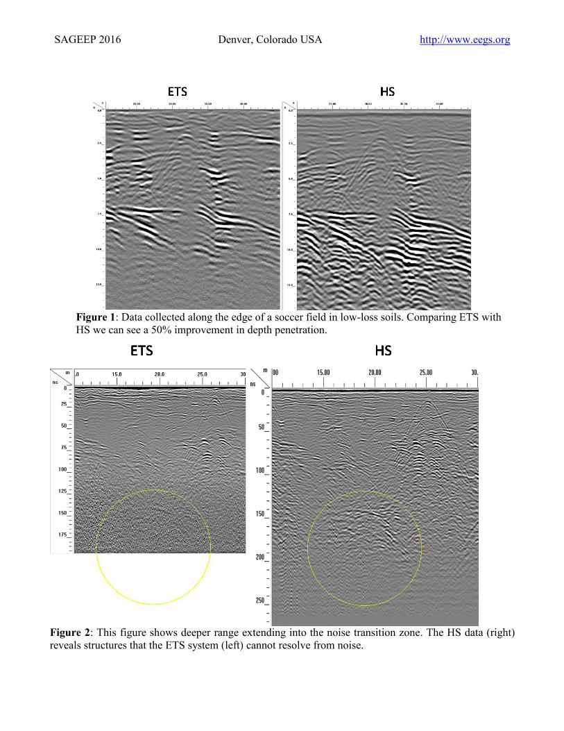
Figure 1: Data collected along the edge of a soccer field in low-loss soils. Comparing ETS with
HS we can see a 50% improvement in depth penetration.
Figure 2: This figure shows deeper range extending into the noise transition zone. The HS data (right)
reveals structures that the ETS system (left) cannot resolve from noise.
SAGEEP 2016 Denver, Colorado USA http://www.eegs.org
Figure 2 compares similar data but this time using ranges that exceed the signal penetration of
either system. For the ETS system, the signal floor is about 125ns, while the HS signal floor is about
200ns. Again structures obscured in the noise of the ETS system are clearly resolved using the HS
implementation.
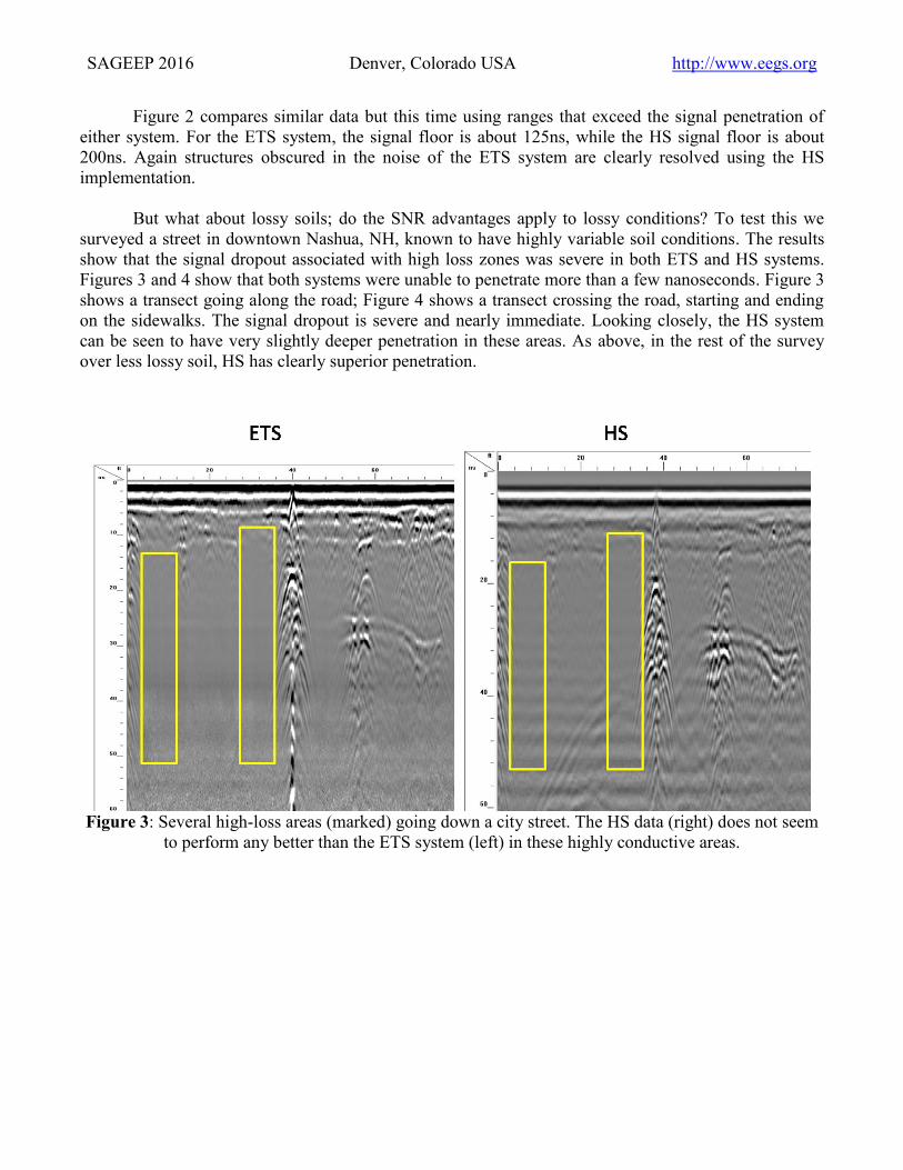
But what about lossy soils; do the SNR advantages apply to lossy conditions? To test this we
surveyed a street in downtown Nashua, NH, known to have highly variable soil conditions. The results
show that the signal dropout associated with high loss zones was severe in both ETS and HS systems.
Figures 3 and 4 show that both systems were unable to penetrate more than a few nanoseconds. Figure 3
shows a transect going along the road; Figure 4 shows a transect crossing the road, starting and ending
on the sidewalks. The signal dropout is severe and nearly immediate. Looking closely, the HS system
can be seen to have very slightly deeper penetration in these areas. As above, in the rest of the survey
over less lossy soil, HS has clearly superior penetration.
Figure 3: Several high-loss areas (marked) going down a city street. The HS data (right) does not seem
to perform any better than the ETS system (left) in these highly conductive areas.
SAGEEP 2016 Denver, Colorado USA http://www.eegs.org
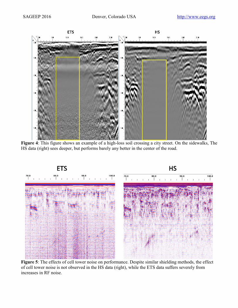
Figure 4: This figure shows an example of a high-loss soil crossing a city street. On the sidewalks, The
HS data (right) sees deeper, but performs barely any better in the center of the road.
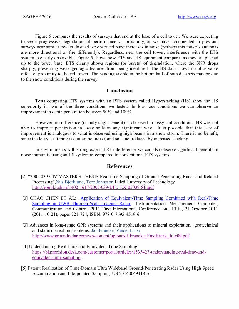
Figure 5: The effects of cell tower noise on performance. Despite similar shielding methods, the effect
of cell tower noise is not observed in the HS data (right), while the ETS data suffers severely from
increases in RF noise.
SAGEEP 2016 Denver, Colorado USA http://www.eegs.org
Figure 5 compares the results of surveys that end at the base of a cell tower. We were expecting
to see a progressive degradation of performance vs. proximity, as we have documented in previous
surveys near similar towers. Instead we observed burst increases in noise (perhaps this tower’s antennas
are more directional or fire differently). Regardless, near the cell tower, interference with the ETS
system is clearly observable. Figure 5 shows how ETS and HS equipment compares as they are pushed
up to the tower base. ETS clearly shows regions (or bursts) of degradation, where the SNR drops
sharply, preventing weak geologic features from being identified. The HS data shows no observable
effect of proximity to the cell tower. The banding visible in the bottom half of both data sets may be due
to the snow conditions during the survey.
Conclusion
Tests comparing ETS systems with an RTS system called Hyperstacking (HS) show the HS
superiority in two of the three conditions we tested. In low loss conditions we can observe an
improvement in depth penetration between 50% and 100%.
However, no difference (or only slight benefit) is observed in lossy soil conditions. HS was not
able to improve penetration in lossy soils in any significant way. It is possible that this lack of
improvement is analogous to what is observed using high beams in a snow storm. There is no benefit,
since the lossy scattering is clutter, not noise, and so is not reduced by increased stacking.
In environments with strong external RF interference, we can also observe significant benefits in
noise immunity using an HS system as compared to conventional ETS systems.
References
[2] “2005:039 CIV MASTER'S THESIS Real-time Sampling of Ground Penetrating Radar and Related
Processing”,Nils Björklund, Tore Johnsson Luleå University of Technology
http://epubl.luth.se/1402-1617/2005/039/LTU-EX-05039-SE.pdf
[3] CHAO CHEN ET AL: "Application of Equivalent-Time Sampling Combined with Real-Time
Sampling in UWB Through-Wall Imaging Radar", Instrumentation, Measurement, Computer,
Communication and Control, 2011 First International Conference on, IEEE., 21 October 2011
(2011-10-21), pages 721-724, ISBN: 978-0-7695-4519-6
[3] Advances in long-range GPR systems and their applications to mineral exploration, geotechnical
and static correction problems. Jan Francke, Vincent Utsi
http://www.groundradar.com/wp-content/uploads/J.Francke_FirstBreak_July09.pdf
[4] Understanding Real Time and Equivalent Time Sampling,
https://bkprecision.desk.com/customer/portal/articles/1535427-understanding-real-time-and-
equivalent-time-sampling,.
[5] Patent: Realization of Time-Domain Ultra Wideband Ground-Penetrating Radar Using High Speed
Accumulation and Interpolated Sampling US 20140049418 A1