EVALUATION OF FIRST ARTICLES OF FRODUCTION RADIO RECEIVING ... · EVALUATION OF FIRST ARTICLES OF...
32
VADC TECHNICAL REPORT 52-146 EVALUATION OF FIRST ARTICLES OF FRODUCTION RADIO RECEIVING SET AN/ARN-18 BERNARD H. DELL "COMMUNICATION AND NAVIGATION LABORATORY JULY 1952 WRIGHT AIR DEVELOPMENT CENTER
Transcript of EVALUATION OF FIRST ARTICLES OF FRODUCTION RADIO RECEIVING ... · EVALUATION OF FIRST ARTICLES OF...
VADC TECHNICAL REPORT 52-146
EVALUATION OF FIRST ARTICLES OF FRODUCTIONRADIO RECEIVING SET AN/ARN-18
BERNARD H. DELL"COMMUNICATION AND NAVIGATION LABORATORY
JULY 1952
WRIGHT AIR DEVELOPMENT CENTER
NOTICES
'When Government drawings, specifications, or other data are usedfor any purpose other than in connection with a definitely related Govern-ment procurement operation, the United States Government thereby in-cur s no responsibility nor any obligation whatsoever; and the fact thatthe Government may have formulated, furnished, or in any way suppliedthe said drawings, specifications, or other data, Is not to be regardedby implication or otherwise as in any manner licensing the holder orany other person or corporation,or conveying any rights or permissionto manufacture, use, or sell any patented invention that may in any waybe related thereto.
The information furnished herewith is made available for studyupon the understanding that the Government's proprietary interests inand relating thereto shall not be impaired. It is desired that the JudgeAdvocate (WCI), Wright Air Development Center, Wright -PattersonAir Force Base, Ohio, be promptly notified of any apparent conflict be-tween the Government's proprietary interests and those of others.
WADC TECHNICAL REPORT 52-146
EVALUATION OF FIRST ARTICLES OF PRODUCTIONRADIO RECEIVING SET AN/ARN- 18
Bernard H. DellCommunication & Navigation Laboratory
July 1952
SEA No. S-2
Wright Air Development CenterAir Research and Development Command
United States Air ForceWright-Patterson Air Force Base, Ohio
McGregor & Werner, Inc., Wakefield, Mass.Oct. 22. 1952 100
FOPREORD
This report was prepared by the Communication and Navigation Laboratory,wriiht Air Development Center, to record the results of tests conducted onFirst Articles of Production of Radio Receiving Set AN/ARI-I$ developed andproduced by Crosley Division, AVCO Manufacturing Corporation, under ContractNo. AF 33(035)-18561; Emerson Radio and Television Corporation under ContractNo. AF 33(03r)-18559; and Pacific Mercury Television Corporation under Con-tract No. AF 33(038)-1856o. Mr. William F. Neill, Ir. Leon F. Vangunten, andMr. Bernard 11. Dell were the Communication and Navigation Laboratory projectengineers. The evaluation was conducted under Service Engineering AccountS-2, "'ork Performed for the Directorate, Procurement and Industrial Planning."
WADC TR 52-iJh6
ABSTRACT
Crosley Division, AVCO Manufacturing Corporation; Emerson Radio and Tele-vision Corporation; and Pacific Mercury Television Corporation were simultane-ously awarded contracts to develop and produce Radio Receiving Sets AN/ARN-18(Glide Slope Receiver) in accordance with Military Specification MIL-R-6201dated 31 August 1950. MIL-R-6201 was written so as to combine the betterfeatures of development 20-channel glide slope receivers designed by CollinsRadio Company and Federal Telephone and Radio Corporation. The receiver wasdeveloped jointly by the three contractors who pooled their engineering facili-ties and performed most of the work at the Crosley Division plant. Six FirstArticles of production were built at Crosley and submitted for tests and ap-proval. The results of the tests conducted on these First Articles indicatedthat the receivers failed to meet some of the requirements of SpecificationMIL-R-6201. However, this receiver represented an improvement over thedevelopment models AN/ARN-18(XA-1) and AN/ARN-l8(XA-2), and a considerableimprovement over the Air Force Standard, Radio Receiving Equipment AN/ARN-5().In the opinion of the WADC project engineers, the design was as good as thecurrent state of the art would permit. Therefore, during the pilot runs, whichhad their inception in August 1951, production approval was granted to all threecontractors.
PUBLICATION REVIEW
This report has been reviewed and is approved.
FOR THE COMMANDING GENERAL:
Colonel, USAFChief, Weapons Components Division
WADC TR 52-146 iii
TABLE OF CONTENTS
PAGE
SECTIONi - INTRODUCTIOI... .. ............ ............ 1SECTION II - TEST RESULTS ..... ...... ............ ..... 1SECTION III - EVALUATIONS AND CONCLUSIONS . . . ....... ............ 20APPENDIX -PHOTOCAPHS .O.............. ........... 21
LIST OF TABLES
PAGE
I Test Equipment Used . . ......... ......... • 1II RF Input vs Output... . . . .. . . 3
III Automatic Gain Control. . ..... • • •. • • .... e • 4IV Sensitivity vs Channel Frequency......... • .e • • • . 4
V Selectivity .. • . . .. . . 7VI Receivers in Parallel ..................... 9
VII Undesired Responses .... a ..... .... ...... 9VIII Harmonic Distortion & Intermodulation . . ... ... .... 10
IX Range of Controls ......... ...... ... .11X Current Drain . . .1 . . . . . . . . . .... . 11
XI Warm-Up Characteristics o a e ........ 12XII Resonant Frequency Stability . . . . . . . . . ........ 12
XIII Sensitivity vs AC & DC Voltages . . .. ........... 13XIV Temperature Variations . ....... * ........... 13
XV Humidity Testing.... ..... .. . . . . . . . . . . 15XVI Deflection Linearity* . ... . e............... 16
XVII Shock Test. . .9 9 9 * 9 9 9 9 9 9 * .* .9* 18XVIII Vibration . . . . . . . . .& * * • 0 * 0 * a 18
XIX Life Tett . . . . . . . . * . o . 9 • • * • • • 9 .. 0 a • • 19
LIST OF ILLUSTRATIONS
FIGURE PAGE
1. Deflection Sensitivity vs RF input . . ....... .. . .. 62. RF Selectivity.............. • • . . ..... * • S3. Deflection Linearity . ..a... ne n e" 9. 174. Radio Receiver R-322/ARN-lS on Mounting MT-691/ARN-tl
(Diagonal Front View) . . . . . . . . . 9 9 . 215. Mounting MT-691/ARN-lS (Diagonal Front View).:. • . 0 . 216. Radio Receiver R-322/ARN-lS (Interior Left Side View-
Cover Removed) ........... . . . .. .. .e 21
WADC TR 52-146 iv
LIST OF ILLUSTRATIONS - continued
FIGURE PAGE
7. Radio Receiver R-322/ARN-I9 (Interior Right Side View -
Cover and Crystal Housing Removed). .# a * , • 228. Radio Receiver R-322/ARN-18 (Interior Right Side View-
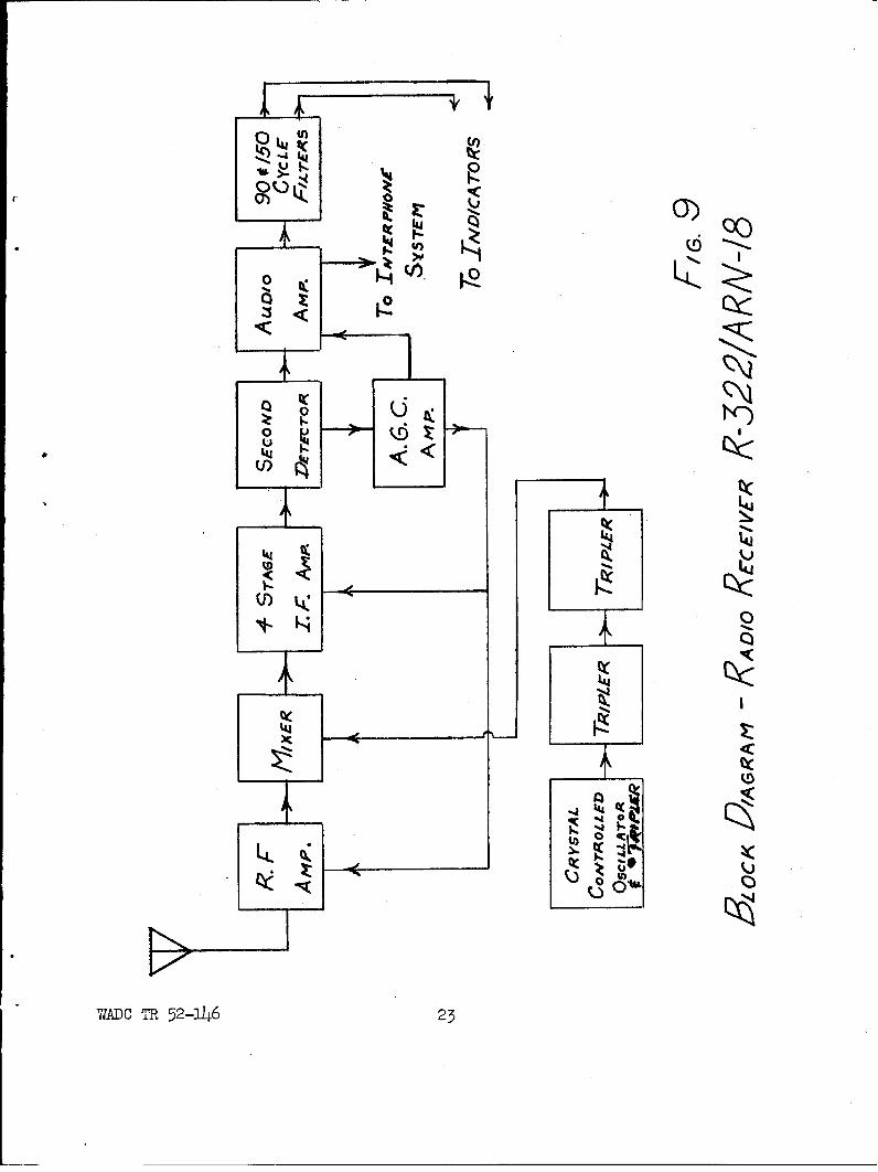
Cover Removed).. -* -oee o . . , * * .9 9 e 229. Block Diagram - Radio Receiver R-322/ARN-lS . . . . . . . . . 23
WADC TR-52-31T6 v
SECTION I - INTRODUCTION
On 3 January 1951 contracts were awarded to Crosley Division., AVCO 1Manufac-turing Corporation; Emerson Radio and Television Corporation; and Pacific 1iercuryTelevision Corporation to develop and produce Radio Receiving Set AIN/ARN-18(Glide Slope Receiver) in accordance with Specification MIL-R-6201, dated 31August 1951. This specification had been written so as to combine the betterfeatures of two development radio receiving sets as designed by Collins RadioCompany, and Federal Telephone and Radio Corporation.t (For an evaluation ofthese development models refer to Air Force TechnicaiReport 6744., titled "Eval-uation of Development Radio Receiving Sets AN/YURN-18(XA-I) and AN/ARN-lI(XA-2)."
In the interests of uniformity of design, the three contractors agreed todesign the receivers as a joint project at the Crosley Division plant. All draw-ings and schematics were reproduced at Crosley and forwarded to the other twoplants for use in setting up the production facilities. Thus it was possible forall three manufacturers to produce equipment which would be completely electri-cally and mechanically interchangeable. Six First Articles of production werefabricated at Crosley for submission to "J-P AFB for evaluation and acceptanceunder the contracts. In view of the fact that each contractor was obligated tofurnish First Articles, nameplates of each contractor appeared on two of the sixFirst Articles submitted. However, they were all fabricated at Crosley usingCrosley parts and production methods.
This report presents the test results obtained and an evaluation of theFirst Articles as compared to the applicable requirements of ITIL-R-6201, showingwherein the receiver failed to meet the requirements and what action was taken tocorrect the difficulty. In some cases it was determined that the specificationwas in error and amendments were made which would make the requirements of thespecification more realistic. Ina few other cases, before production could be-gin, waivers to IhIL-R-6201 had to be given. In the presentationrf:. -the data, theapplicable requirements of Specification IvIL-R-6201 wiil be given, the data willbe presented and then conment made regarding any amendments or waivers necessarybefore production approval was granted.
SECTION II - TEST RESULTS
In the performance of the tests the following test equipment was used:
TABLE ITEST EQUIWENT USED
Electronic Voltmeter - Ballantine Laboratories, Boonton, N. J.Model 300 #'830 and #2719
Signal Generator - Boonton Radio Corp., Boonton, N. J.LYodel 211 #215Model SG-l #4
71ADC TR 52-146 I
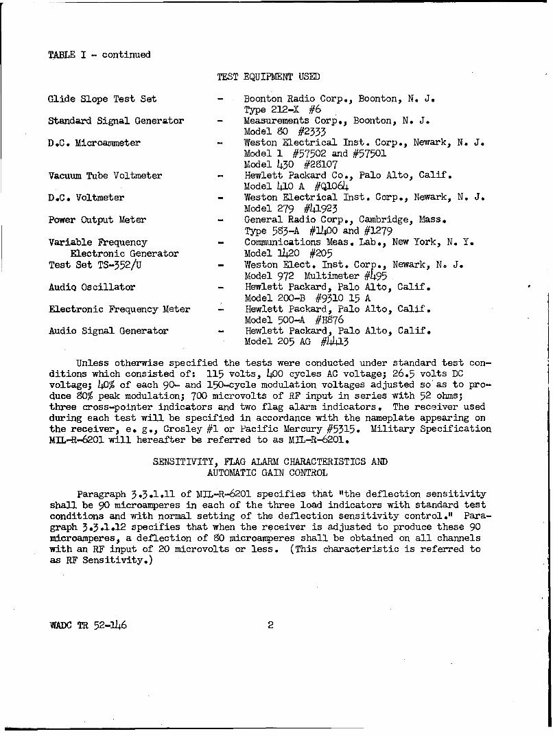
TABLE I - continued
TEST EQUIPMENT USED
Glide Slope Test Set - Boonton Radio Corp., Boonton, N. J.Type 212-X #6
Standard Signal Generator - Measurements Corp., Boonton, N. J.Model 80 #2335
D.C. Microammeter - Weston Electrical Inst. Corp., Newark, N. J.Model 1 #57502 and #57501Model 430 #28107
Vacuum Tube Voltmeter - Hewlett Packard Co., Palo Alto, Calif.Model 410 A #Q1064
D.C. Voltmeter - Weston Electrical Inst. Corp., Newark, N. J.Model 279 #41923
Power Output Meter - General Radio Corp., Cambridge, Mass.Type 583-A #1400 and #1279
Variable Frequency - Communications Meas. Lab., New York, N. Y.Electronic Generator Model 1420 #205
Test Set TS-352/U - Weston Elect. Inst. Corp., Newark, N, J.Model 972 Multimeter #495
AudiQ Oscillator - Hewlett Packard, Palo Alto, Calif.Model 200-B #9310 15 A
Electronic Frequency Meter - Hewlett Packard, Palo Alto, Calif.Model 500-A #H876
Audio Signal Generator - Hewlett Packard, Palo Alto, Calif.Model 205 AG #W1445
Unless otherwise specified the tests were conducted under standard test con-ditions which consisted of: 115 volts, 400 cycles AC voltage; 26.5 volts DCvoltage; 40% of each 90- and 150-cycle modulation voltages adjusted so as to pro-duce 80% peak modulation; 700 microvolts of RF input in series with 52 ohms;three cross-pointer indicators and two flag alarm indicators. The receiver usedduring each test will be specified in accordance with the nameplate appearing onthe receiver, e. g., Crosley #1 or Pacific Mercury #5315. Military SpecificationMIL-R-6201 will hereafter be referred to as MIL-R-6201.
SENSITIVITY, FLAG ALARM CHARACTERISTICS ANDAUTOMATIC GAIN CONTROL
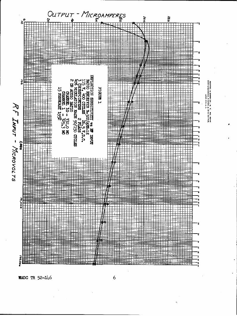
Paragraph 3-5.1.11 of MIL-R-6201 specifies that "the deflection sensitivityshall be 90 microamperes in each of the three load indicators with standard testconditions and with normal setting of the deflection sensitivity control." Para-graph 5.3.1.12 specifies that when the receiver is adjusted to produce these 90microamperes, a deflection of 9O microamperes shall be obtained on all channelswith an RF input of 20 microvolts or less. (This characteristic is referred toas RF Sensitivity.)
WADC TR 52-146 2
Paragraph 3.3.1.17 states that "when standard test conditions prevail andthe receiver is adjusted for standard deflection sensitivity.., the audio asmeasured at the filters shall be within the limits of 0 db and -2 db for any RFsignal level between 40 and 100,000 microvolts." (This is referred to as CourseSoftening.)
5.5.1.23 of MIL-R-6201 specifies that as the RF input is varied from 20 to100,000 microvolts the balance shall not change by more than 5 microamperes.Also in changing from one channel to another the course width shall not changemore than 6 microamperes (course width is defined as the sum of the deflectionsensitivities for the plus 2 db and minus 2 db audio ratio conditions) nor shallthe balance change more than 3 microamperes.
TABLE IIR.F. INPUT VS OUTPUT
Crosley #1 ReceiverR.F. In. 90_c Bal. 150c Total Flag Audio Diode
Channel 1-329.3 mc10 85 2(150) 91 176 308 42.0 1.1020 97 1(150) 101 198 340 42.0 1.3850 94 0 97 191 332 59.4 1.6275 92 0 94 186 325 58.5 1.70
100 90 0 92 182 318 37.5 1.75200 86 0 87 173 502 36.6 1.88500 80 0 82 162 283 33.5 2.00
1k 76 0 79 1%5 270 32.0 2.102k 72 0 74 146 260 30.0 2.195k 67 0 71 138 245 28.7 2.30
l0k 65 0 68 133 235 27.5 2.3920k 62 1(150) 66 128 225 26.5 2.4850k 58 2(150) 62 120 212 24.8 2.56
lOOk 54 2(150) 59 113 200 25.5 2.62
Channel 10-552.0 mc
10 62 5(150) 65 127 220 58.520 100 1(150) 102 202 54L 44 1.2050 99 0 100 199 542 41 1.4675 96 0 97 193 552 59.5 1.54
100 94 0 95 189 528 58.8 1.62200 90 0 90 180 510 56.5 1.75500 85 0 85 166 290 34 1.90750 80 0 81 161 282 53 1.96
lk 78 0 80 158 278 52.2 2.002k 74 0 76 150 264 50.6 2.105k 70 0 72 142 252 29.2 2.22
10k 68 0 70 158 242 28.2 2-5
WADC TR 52-146 3
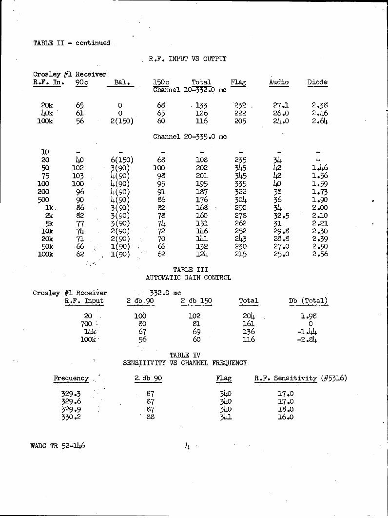
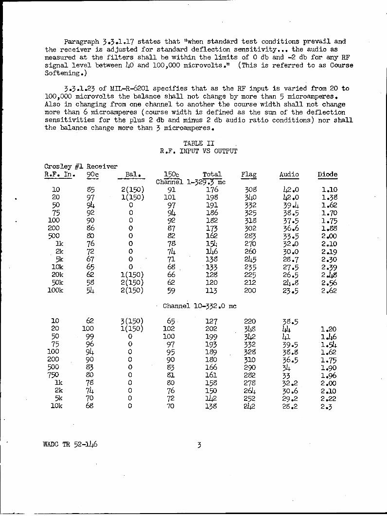
TABLE II - continued
R.F. INPUT VS OUTPUT
Crosley #1 ReceiverR.F. In. 90c Bal. 15Oc Total Flag Audio Diode
-nnel 10-352.0 mc
20k 65 0 68 133 "232 27.1 2.5840k 61 0 65 126 222 26.o 2.46
10ok 56 2(150) 60 116 205 24.0 2.64
Channel 20-335.0 mc
10 - - - - - -
20 40 6(150) 68 108 255 54 -50 102 3(90) 100 202 345 42 1.4675 105 4(90) 98 201 345 42 1.56
100 100 4(90) 95 195 335 40 1.59200 96 4(90) 91 187 322 38 1.73500 90 4(90) 86 176 304 36 1.30
lk 86 3(90) 82 168 290 34 2.002k 82 3(90) 78 160 278 32.5 2.105k 77 3(90) 74 151 262 31 2.21
l0k 74 2(90) 72 146 252 29.8 2.3020k 71 2(90) 70 31a 243 28.8 2.3950k 66 1(90) 66 132 230 27.0 2.50
look 62 1(90) 62 124 215 25.0 2.56
TABLE IIIAUTOMATIC GAIN CONTROL
Crosley #1 Receiver 332.0 mcR.F. Input 2 dbg9 2 db 150 Total Db (Total)
20 100 102 204 1.98700o 80 81 161 01)k 67 69 136 -1 l-4
look: 56 60 116 -2.84
TABLE IVSENSITIVITY VS CHANNEL FREQUENCY
Frequency 2. db 90 Flag R.F. Sensitivity (#5316)
329.3 87 340 17.0329.6 87 340 17.0329.9 87 340 18.0330.2 88 3)1 16.0
WADC TR 52-146 4
TABLE IV - continued
SENSITIVITY VS CHANNEL FREQUENCY
Frequency 2 db 90 Flag R.F. Sensitivity (#5316)
330.5 87 340 17.0330.8 87 54o 17.0331.1 88 345 16.o331.4 88 345 17.0331.7 4 3ý2 18.0332.0 88 345 l.O332.3 89 350 22.0332.6 88 345 18.0332.9 5 4A 19.0
333.2 89 350 17.0333.5 58 349 19.0333.8 88 348 17.0334.1 8 345 18.O3344 88 345 14.0334.7 90 355 16.o335.0 18 .0
These data indicate that the receiver met all the requirements for Deflect-ion Sensitivity and RF Sensitivity with regard to input variations and channelchanges. Channel 20, 335.0 megacycles, of Crosley #1 Receiver was found to havea defective crystal which accounts for its poor response and subsequent failureon that channel The Course Softening characteristic of this receiver was de-signed to meet ie specification as it was later amended.
During the initial design of the receiver it was determined that severalamendments were necessary and have been incorporated in Specification MIL-R-6201A, dated 15 September 1951, which is now being used for all production. Oneof these changes concerns course softening. It was decided that the coursesoftening requirements should be changed to partially agree with those of theCivil Aeronautics Administration (CAA), and so as to fix more rigid limits on thedesign. Originally a course softening control was included in the circuit butthis was deleted in favor of a fixed amount of softening. The requirements ofMIL-R-6201A regarding course softening are as follows:
RF Input - Microvolts Deflection Sensitivity - DB20 -1 to +3
700 014,000 -1 to -3
100,000 -1 1/2 to -4
Crosley #1 Receiver met these requirements.
WADC TR 52-146
OU TPU/T - /I/CROAMPZ-RCS 8
0 00I0
~1"
Hz00
C)
wADO TR 52-a146 6
It was also decided at this time that Standard Deflection Sensitivity shouldbe changed. Hereafter, Standard Deflection Sensitivity will mean with 700 micro-volts of RF input and the audio ratio adjusted for 2 db 90/150 cycles, the cur-rent through each one of three cross-pointer indicators will be 65 microamperes.The new RF Sensitivity requirements are that when the receiver is adjusted to pro-vide 65 microamperes deflection with 700 microvolts input, the deflection for 20microvolts input will be greater than 59 microamperes.
SELECTIVITY
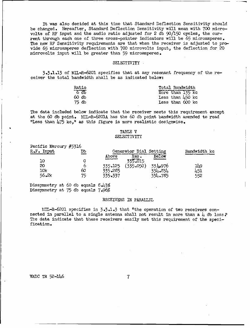
3.5.1.13 of MIL-R-6201 specifies that at any resonant frequency of the re-ceiver the total bandwidth shall be as indicated below:
Ratio Total BandwidthS2bMore than 135 kc
60 db Less than 450 kc75 db Less than 600 kc
The data included below indicate that the receiver meets this requirement exceptat the 60 db point. MIL-R-6201A has the 60 db point bandwidth amended to read"Less than 475 kc," as this figure is more realistic designwise.
TABLE VSELECTIVITY
Pacific Mercury #5316R.F. Input Db Generator Dial Setting Bandwidth kc
Above Res. Below10 0 5.--1520 6 335.125 (535.050) 5M4976 14910k 60 335o.25 354.854 45156.2k 75 355.337 554.7S5 552
Dissymmetry at 60 db equals 8.43%
Dissymmetry at 75 db equals 7.96%
RECEIVERS IN PARALLEL
MIL-R-6201 specifies in 3.5.1.3 that "the operation of two receivers con-nected in parallel to a single antenna shall not result in more than a 4 db lossJ.The data indicate that these receivers easily met this requirement of the speci-fication0
WADC TR 52-146 7
WADOO TRI 52-146 SM
TABLE VIRECEIVERS IN PARALLEL
Crosley #2 and Pacific Mercury #5315 332 mc Std. ConditionsR.F. Input 2 db 90 Bal 2 db 150 Total Flag
#5315 alone 700 69 47-5) 59 1-T 33050K 49 2(90) 44 93 250
#5315 (#2 in parallel) 700 71 4.5(90) 59.5 130.5 53550K 50 2(90) 45 95 250
The RF Sensitivity of #5315 alone was 15 uv. It was 22 uv when #2 was connectedin parallel.
UNDESIRED RESPONSES
3.3.1.14 of MIL-R-6201 specifies that "the following requirements shallapply to all undesired signals regardless of type of service or modulation overa frequency range of 70 to 1700 megacycles:
Adjacent Channel - 90 db downImage - 90 db downIntermediate Frequency - 100 db down
All other spurious responses found in the pass band shall be at least 75 db."The data show that the receiver fell considerably short of the specificationlimits.
In view of the fact that adjacent channel rejection is determined by theselectivity of the receiver, the 90 db requirement for adjacent channel was im-practical. Therefore in MIL-R-6201A this requirement was changed to 70 db.Also, before production began on the three contracts, waivers were granted soas to specify an image rejection of 75 db, an intermediate frequency rejectionof 90 db, and a rejection of all other spurious signals of at least 70 db. Pro-duction receivers meet these requirements.
TABLE VII
UNDESIRED RESPONSES
Pacific Mercury #5316
Adjacent Channel Rejection - greater than 70 db.Image Rejection - greater than 70 db.IF Rejection - greater than 90 db.All Other Spurious Responses at Least 74 db down.
HARMONIC DISTORTION
MIL-R-6201 specifies that for any RF signal between 40 and 100,000 micro-volts modulated simultaneously with equal amounts of 90- and 150-cycle modulatingvoltages (adjusted so as to produce 90% peak modulation) the percentage total
WADC TR 52-146 9
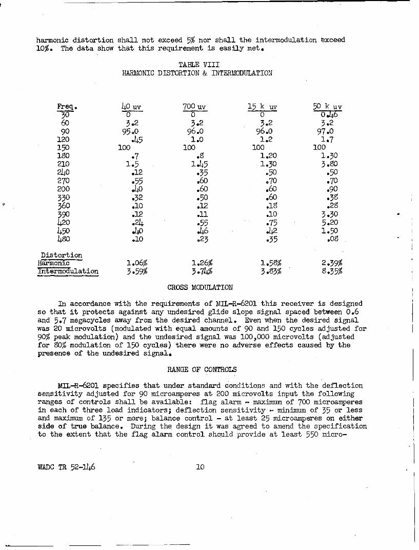
harmonic distortion shall not exceed 5% nor shall the intermodulation exceed10%. The data show that this requirement is easily met.
TABLE VIIIHARMONIC DISTORTION & INTERMODULATION
Freq. 40 uv 70 0 uv 15 k uv 50 k uv30 0 0 0 o Z760 3.2 3.2 3.2 3.290 95.0 96.o 96.o 97.0
120 .45 1.0 1.2 1.7150 100 100 100 1001i0 .7 .8 1.20 1.30210 1.5 1.45 1.30 3-.0240 .12 .35 .50 .50270 .55 .60 .70 .70200 .40 .60 .60 .90330 .32 .50 .60 .58360 .10 .12 .18 .28390 .12 .11 .10 3.30420 .24 .55 .75 5.20450 .40 .46 .42 1.50480 .10 .23 .35 .08
DistortionHarmonic 1.06% 1.26% 1.59% 2.39%Intermodiulation 3.59% 3.74% 3.83% 8.35%
CROSS MODULATION
In accordance with the requirements of MIL-R-6201 this receiver is designedso that it protects against any undesired glide slope signal spaced between 0.6and 5.7 megacycles away from the desired channel. Even when the desired signalwas 20 microvolts (modulated with equal amounts of 90 and 150 cycles adjusted for90% peak modulation) and the undesired signal was 100,000 microvolts (adjustedfor 80% modulation of 150 cycles) there were no adverse effects caused by thepresence of the undesired signal.
RANGE OF CONTROLS
MIL-R-6201 specifies that under standard conditions and with the deflectionsensitivity adjusted for 90 microamperes at 200 microvolts input the followingranges of controls shall be available: flag alarm - maximum of 700 microamperesin each of three load indicators; deflection sensitivity - minimum of 35 or lessand maximum of 135 or more; balance control - at least 25 microamperes on eitherside of true balance. During the design it was agreed to amend the specificationto the extent that the flag alarm control should provide at least 550 micro-
WADC TR 52-146 10
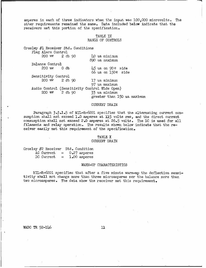
amperes in each of three indicators when the input was 100,000 microvolts. Theother requirements remained the same. Data included below indicate that thereceivers met this portion of the specification.
TABLE IXRANGE OF CONTROLS
Crosley #1 Receiver Std. ConditionsFlag Alarm Control
200 uv 2 db 90 40 ua minimum890 ua maximum
Balance Control200 uv 0 db 45 ua on 90c side
66 ua on 150c sideSensitivity Control
200 uv 2 db 90 17 ua minimum97 ua maximum
Audio Control (Sensitivity Control Wide Open)200 uv 2 db 90 33 ua minimum
greater than 150 ua maximum
CURRENT DRAIN
Paragraph 3.3.1.5 of MIL-R-6201 specifies that the alternating current con-sumption shall not exceed 1.0 amperes at 115 volts rms, and the direct currentconsumption shall not exceed 2.0 amperes at 26.5 volts. The DC is used for allfilaments and relay operation. The results shown below indicate that the re-ceiver easily met this requirement of the specification.
TABLE XCURRENT DRAIN
Crosley #2 Receiver Std. ConditionAC Current - 0.27 amperesDC Current - 1.00 amperes
WARM-UP CHARACTERISTICS
MIL-R-6201 specifies that after a five minute warm-up the deflection sensi-tivity shall not change more than three microamperes nor the balance more thantwo microamperes. The data show the receiver met this requirement.
WADC TR 52-146 l
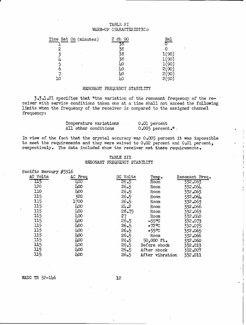
TABLE XI
WARM-UP CHARACTERISTIC S
Time Set On (minutes) 2 db 90 Bal1 37 7--2 38 03 3S 1(90)4 38 1(90)5 40 1(90)6 40 2(90)7 40 2(90)
10 40 2(90)
RESONANT FREQUENCY STABILITY
3.3.1.21 specifies that "the variation of the resonant frequency of the re-ceiver with service conditions taken. one at a time shall not exceed the followinglimits when the frequency of the receiver is compared to the assigned channelfrequency:
Temperature variations 0.01 percentAll other conditions 0.005 percent."
In view of the fact that the crystal accuracy was 0.005 percent it was impossibleto meet the requirements and they were waived to 0.02 percent and 0.01 percent,respectively. The data included show the receiver met these requirements.
TABLE XIIRESONANT FREQUENCY STABILITY
Pacific Mercury #5316AC Volts AC Freq DC Volts Temp. Resonant Freq.
I1O5 400 2.5 Room 332.063120 400 26.5 Room 332.064110 400 26.5 Room 332.063115 320 26.5 Room 332.064115 1700 26.5 Room 332.063115 400 24.2 Room 332.066115 400 2S.75 Room 332.063115 400 27 Room 332.040115 400 26.5 -550C 332 .073115 400 26.5 +72 0 C 332.075115 400 26.5 +550 C 332.065115 400 26.5 Room 332.066115 400 26.5 50,000 ft. 332.060115 400 26.5 Before shock 332.013115 400 26.5 After shock 332.007115 400 26.5 After vibration 332.011
WADO TR 52-146 12
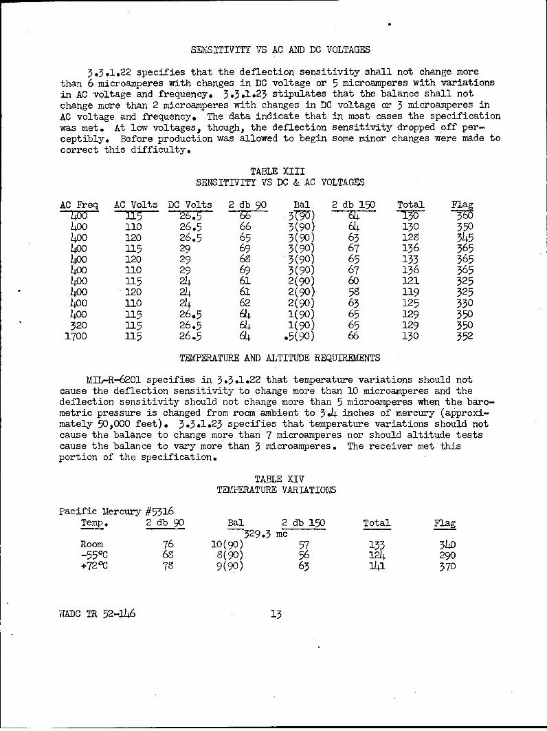
SENSITIVITY VS AC AND DC VOLTAGES
5.3.1.22 specifies that the deflection sensitivity shall not change morethan 6 microamperes with changes in DC voltage or 5 microamperes with variationsin AC voltage and frequency. 3.5.1.23 stipulates that the balance shall notchange more than 2 microamperes with changes in DC voltage or 3 microamperes inAC voltage and frequency. The data indicate that in most cases the specificationwas met. At low voltages, though, the deflection sensitivity dropped off per-ceptibly. Before production was allowed to begin some minor changes were made tocorrect this difficulty.
TABLE XIIISENSITIVITY VS DC & AC VOLTAGES
AC Freq AC Volts DC Volts 2 db 90 Bal 2 db 150 Total FlagT00 l5 376 W ) 64 30M400 110 26.5 66 3(90) 64 130 550400 120 26.5 65 5(90) 65 12S 545400 115 29 69 3(90) 67 136 565400 120 29 68 3(90) 65 133 365400 110 29 69 3(90) 67 136 565400 115 24 61 2(90) 60 121 325400 120 24 61 2(90) 58 119 525400 110 24 62 2(90) 65 125 550400 115 26.5 64 1(90) 65 129 550320 115 26.5 64 1(90) 65 129 550
1700 115 26.5 64 .5(90) 66 130 552
TEMPERATURE AND ALTITUDE REQUIREMENTS
MIL-R-6201 specifies in 5.5.1.22 that temperature variations should notcause the deflection sensitivity to change more than 10 microamperes and thedeflection sensitivity should not change more than 5 microamperes when the baro-metric pressure is changed from room ambient to 354 inches of mercury (approxi-mately 50,000 feet). 3.5.1.23 specifies that temperature variations should notcause the balance to change more than 7 microamperes nor should altitude testscause the balance to vary more than 5 microamperes. The receiver met thisportion of the specification.
TABLE XIVTEMPERATURE VARIATIONS
Pacific Mercury #5316Temp. 2 db 90 Bal 2 db 150 Total Flag
529.5 mcRoom 76 10(90) 57 133 340-55 0 C 68 8(90) 56 124 290+720 C 78 9(90) 63 31$ 570
WADC TR 52-146 15
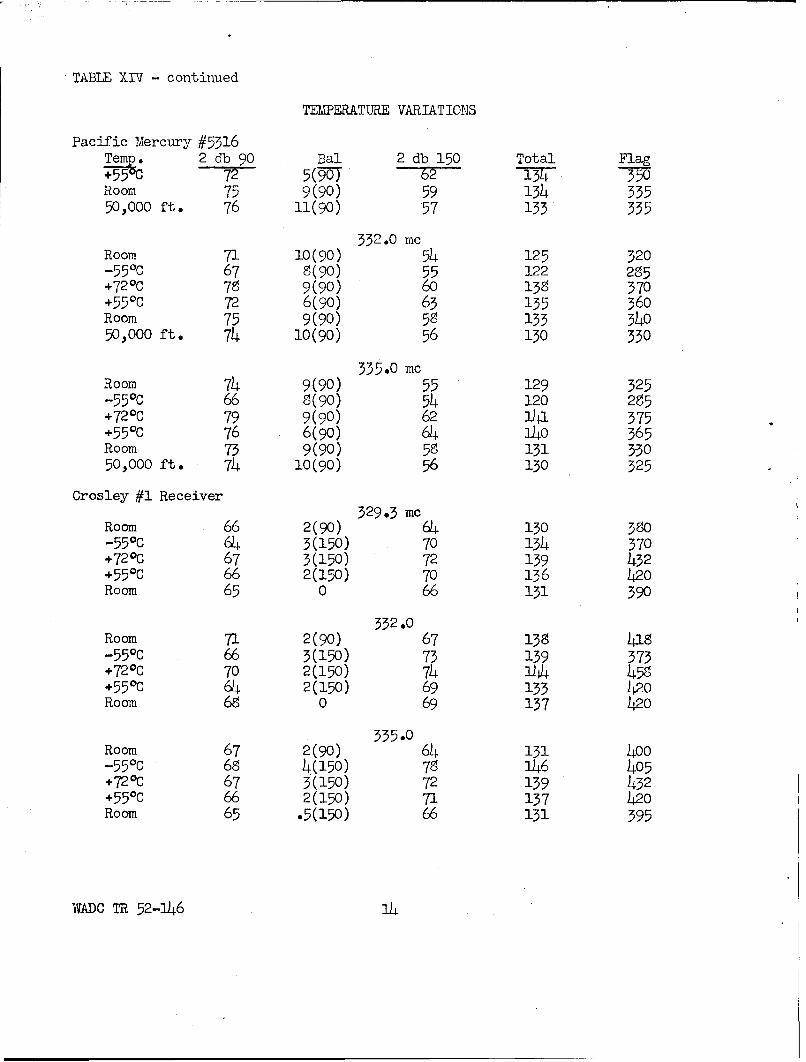
TABLE XIV - continued
TEMMERATURE VARIATIONS
Pacific Mercury #5316Temp. 2 db 90 Bal 2 db 150 Total Flag
+5 25(-907)6 17F 350Room 75 9(90) 59 134 33550,000 ft. 76 11(90) 57 133 335
332.0 mcRoom 71 10(90) 54 125 320-55 0 C 67 8(90) 55 122 285+720C 79 9(90) 60 13 3570+550 C 72 6(90) 63 135 360Room 75 9(90) 58 133 34050,000 ft. 74 10(90) 56 130 330
335.0 mcRoom 74 9(90) 55 129 325-55 0C 66 8(90) 54 120 285+720C 79 9(90) 62 141 375+550 C 76 6(90) 64 140 365Room 73 9(90) 58 131 33050,000 ft. 74 10(90) 56 130 325
Crosley #1 Receiver329.3 mc
Room 66 2(90) 64 130 380-55°C 64 3(150) 70 134 370+720C 67 3(150) 72 139 432+55ec 66 2(150) 70 156 420Room 65 0 66 131 390
Room 71 2(90) 67 138 418-550c 66 3(150) 73 139 373+720C 70 2(150) 74 L4 458+55 0 C 64 2(150) 69 133 420Room 68 0 69 137 420
335.0Room 67 2(90) 64 131 400-550c 68 4(150) 78 146 405+720C 67 3(150) 72 139 432+550C 66 2(150) 71 137 420Room 65 .5(150) 66 131 395
WADC TR 52-J46 1
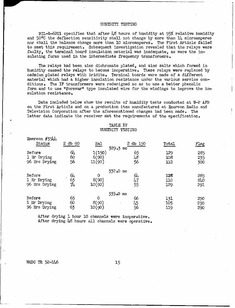
HUUMDITY TESTING
MIL-R-6201 specifies, that after 49 hours of humidity at 95% relative humidityand 500C the deflection sensitivity shall not change by more than 14 microamperesnor shall the balance change more than 10 microamperes. The First Article failedto meet this requirement. Subsequent investigation revealed that the relays werefaulty, the terminal board insulation material was inadequate, as were the in-sulating forms used in the intermediate frequency transformers.
The relays had been zinc dichromate plated, and zinc salts which formed inhumidity caused the relays to become inoperative. These relays were replaced bycadmium plated relays with iridite. Terminal boards were made of a differentmaterial which had a higher insulation resistance under the various service con-ditions. The IF transformers were redesigned so as to use a better phenolicform and to use "Formvar" type insulated wire for the windings to improve the in-sulation resistance.
Data included below show the results of humidity tests conducted at W-P AFBon the First Article and on a production item manufactured at Emerson Radio andTelevision Corporation after the aforementioned changes had been made. Thelatter data indicate the receiver mfet the requirements of the specification.
TABLE XVHMUEDITY TESTING
Emerson #35W4Status 2 db 90 Bal 2 db 150 Total Flag
329.3 mcBefore 64 1(150) 65 129 2851 Hr Drying 60 6(90) 49 109 23596 Hrs Drying 56 11(90) 56 112 500
332.0 mcBefore 64 0 64 129 2951 Hr Drying 63 8(90) 47 110 24096 Hrs Drying 74 10(90) 55 129 291
335.0 mcBefore 65 0 66 131 2901 Hr Drying 60 8(90) 45 105 23096 Hrs Drying 63 10(90) 56 119 290
After drying 1 hour 10 channels were inoperative.After drying 48 hours all channels were operative.
WADC TR 52-146 15
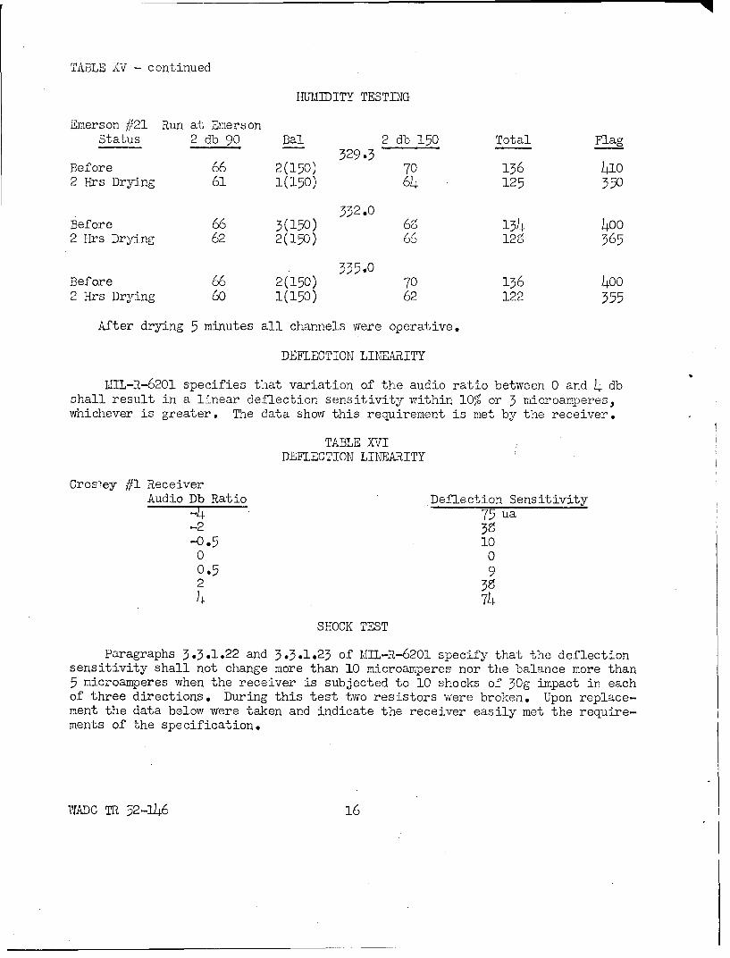
TABLE XV - continued
HU1,JTITY TESTING
Emerson #21 Run at EmersonStatus 2 db 90 Bal 2 db 150 Total Flag
329.3Before 66 2(150) 70 136 4102 Hrs Drying 61 1(150) 64 125 350
332.0
Before 66 3(150) 134 4002 Hrs Drying 62 2(150) 66 128 365
335.0Before 66 2(150) 70 136 4002 Hrs Drying 60 1(150) 62 122 355
After drying 5 minutes all channels were operative.
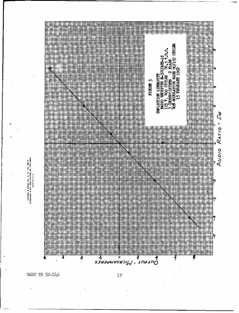
DEFLECTION LINEARITY
UIL-R-6201 specifies that variation of the audio ratio between 0 and 4 dbshall result in a linear deflection sensitivity within 10% or 3 microamperes,whichever is greater. The data show this requirement is met by the receiver.
TABLE XVIDEFLECTION LINEARITY
Cros-ey #1 ReceiverAudio Db Ratio Deflection Sensitivity
-4 75 ua-2 38-0.5 10
0 00.5 92 394 74
SHOCK TEST
Paragraphs 3.3.1.22 and 3.3.1.23 of 1MIL-R-6201 specify that the deflectionsensitivity shall not change more than 10 microamperes nor the balance more than5 microamperes when the receiver is subjected to 10 shocks of 30g impact in eachof three directions. During this test two resistors were broken. Upon replace-ment the data below were taken and indicate the receiver easily met the require-ments of the specification.
W'ADC TR 52-146 16
.... ........ .. .......... .... ....................... .. ........... ......
.... .. ....I ...... ...... .... .. ............ ..... ..... ..... . ..... .... .. H I..... .... ..... ...... H I+H++i±. I I 11. 1
... ... ......... .... ..... .....
... ... ... .... .
... ... ... .... .
m ............... ...... .
lbo........... H P- mm
--------- - --------------
- 4W V
M-1 -1
w t r-4
4 mm Im: --- -----
-:: ...T.
M:X
w:
MMMM"
... ... - - ----- ----- - HI
a
0
mm
. ..............
- -----------
67
r
u T
.. .. . .... . . ........... .. ......M
-- - --- -- --- T
ýHH i- -- fE H±
IE 1: R -44 RH IH HER
G-7b,"ivvoywýV i nta no
TIADC TR 52-1.46 17
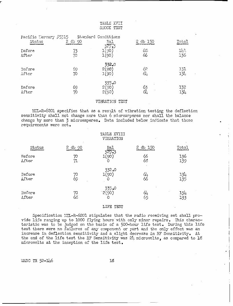
TABLE XVIISHOCK TEST
Pacific mercury ,//515 Standard ConditionsStatus 2 db 90 Bal 2 db 150 Total
Before 73 1(90) 6,. -After 70 1(90) 66 136
332.0Before 69 2 (90) 62 131After 70 1(90) 64 134
335.0Before 69 2(90) 63 132After 70 2(90) 64 134
VIBRATION TEST
MIL-R-6201 specifies that as a result of vibration testing the deflectionsensitivity shall not change more than 6 microamperes nor shall the balancechange by more than 3 microamperes. Data included below indicate that theserequirenents were met.
TABLE XVIIIVIBRATION
Status 2 db 90 Bal 2 db 150 Total
Before 70 1(90) 66 136After 71 0 68 139
332.0Before 70 1(90) 64 134After 69 0 66 135
335.0Before 70 2(90) 64 134After 68 0 65 133
LIFE TEST
Specification MIL-R-6201 stipulates that the radio receiving set shall pro-vide life ranging up to 1000 flying hours with only minor repairs. This charac-teristic was to be judged on the basis of a 500-hour life test. During this lifetest there were no failures of any component or part and the only effect was anincrease in deflection sensitivity and a slight decrease in RF Sensitivity. Atthe end of the life test the RF Sensitivity was 24 microvolts, as compared to 18microvolts at the inception of the life test.
,ADC TR 52-146 18
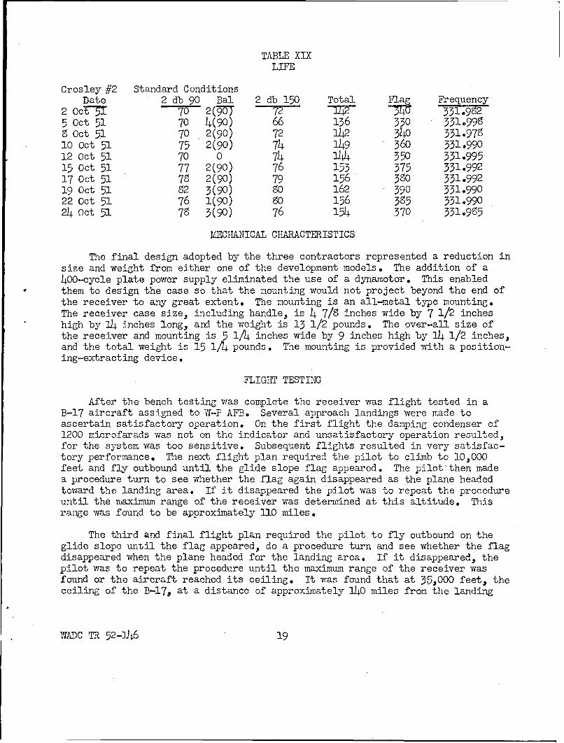
TABLE XIXLIFE
Crosley #2 Standard ConditionsDate 2 db 90 Bal 2 db 150 Total Flag Frequency
2 Oct-T 70 2(97 72 W 331.9925 Oct 51 70 4(90) 66 136 330 331.9988 Oct 51 70 2(90) 72 1L2 340 331.97910 Oct 51 75 2(90) 74 149 360 331.99012 Oct 51 7Q 0 74 144 350 331.99515 Oct 51 77 2(90) 76 153 375 331.99217 Oct 51 78 2(90) 79 156 380 331.99219 Oct 51 82 3(90) 80 162 390 331.99022 Oct 51 76 1(90) 80 156 385 331.99024 Oct 51 78 3(90) 76 154 370 331.995
KECHANICAL CHARACTERISTICS
The final design adopted by the three contractors represented a reduction insize and weight from either one of the development models. The addition of a400-cycle plate power supply eliminated the use of a dynamotor. This enabledthem to design the case so that the mounting would not project beyond the end ofthe receiver to any great extent* The mounting is an all-metal type mounting.The receiver case size, including handle, is 4 7/9 inches wide by 7 1/2 incheshigh by 14 inches long, and the weight is 13 1/2 pounds. The over-all size ofthe receiver and mounting is 5 M4 inches wide by 9 inches high by 14 1/2 inches,and the total weight is 15 1/4 pounds. The mounting is provided with a position-ing-extracting device.
FLIGHT TESTING
After the bench testing was complete the receiver was flight tested in aB-17 aircraft assigned to W-P AFB, Several approach landings were made toascertain satisfactory operation. On the first flight the damping condenser of1200 microfarads was not on the indicator and unsatisfactory operation resulted,for the system was too sensitive. Subsequent flights resulted in very satisfac-tory performance. The next flight plan required the pilot to climb to 10,000feet and fly outbound until the glide slope flag appeared. The pilot'then madea procedure turn to see whether the flag again disappeared as the plane headedtoward the landing area. If it disappeared the pilot was to repeat the procedureuntil the maximum range of the receiver was determined at this altitude. Thisrange was found to be approximately 110 miles.
The third and final flight plan required the pilot to fly outbound on theglide slope until the flag appeared, do a procedure turn and see whether the flagdisappeared when the plane headed for the landing area. If it disappeared, thepilot was to repeat the procedure until the maximum range of the receiver wasfound or the aircraft reached its ceiling. It was found that at 3.5,000 feet, theceiling of the B-17, at a distance of approximately 140 miles from the landing
WADC TR 52-146 19
area the glide slope signal was still being received in sufficient strength, whenheading toward the runway, to cause the glide slope flag to disappear. Theseflights were conducted using Antenna AT-l06/ARN, a flush-mounted, bathtub typeantenna designed by the C&N Laboratory, mounted in the nose of the aircraft.Similar results have also been obtained using a commercial type Collins 37P-2(Antenna AT-326/ARN) mounted externally on the nose.
III - EVALUATIONS AND CONCLUSIONS
The basic electrical specifications as met by this receiver can be summa-rized as follows: there are 20 channels of operation spaced 0.3 megacycles apartin the band from 329.3 to 335.0 megacycles. The resonant frequency stabilityunder all service conditions is 0.02% or better. With the balance adjusted for0 microamperes and the total deflection sensitivity adjusted for 130 microamperesin each of three load indicators, the deflection sensitivity stability under allservice conditions is 130 ± 14 microamperes, while the on course (balance)stability is 0 ± 10 microamperes.
The rejection of undesired responses is at least 74 db with adjacent channelrejection being 70 db or greater. The selectivity curve is such that at the 6-db point the total bandwidth is greater than 135 kc and at the 75-db point thebandwidth is less than 600 kc. Harmonic distortion is less than 5% and inter-modulation is less than 10%. Cross modulation has essentially no effect on theproper operation of the receiver nor does 2 volts of ripple of any frequency be-tween 30 and 20,000 cycles per second when injected into the AC or DC power leads.
The receiver and mounting have a vibration resonant frequency less than 12cycles per second in all directions, and neither vibration nor shock, up to 30 g,materially affects the operation of the receiving set. The mounting operatesvery effectively under all service conditions including cold temperatures.
Flight results proved this receiver to be the most sensitive glide slopereceiver tested to date, and the range of 140 miles obtained is considered ex-cellent. This range will enable aircraft flying at high altitudes to pick upthe glide slope at the high altitude and fly it right in to the landing area.Judging from the results of the life test, this receiver should be a highlyreliable receiver requiring very little maintenance.
This receiver represents a substantial improvement over Radio Receiving SetAN/ARN-5( ) and will replace it as a Standard Item as soon as service tests canbe conducted. At the present time both the AN/ARN-5( ) and the AN/ARN-l8 areclassified "Substitute Standard."
In evaluating this radio receiving set it was believed that the designrepresents the ultimate that the present state of the art permitted. In view ofthe urgency attached to the production, the contractors were given production ap-proval in September 1951 during the conducting of pilot runs. As of 1 February1952 approximately 4000 Radio Receiving Sets AN/ARN-l8 have been built and de-livered by the three contractors.
WADC TR-52 -146 20
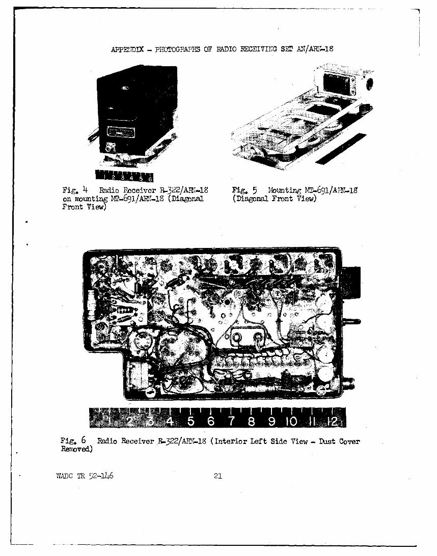
APPENITDX -PHOTO&1RAPIES OF RADIO REOBIVINIG- SET UT/ARlv19S
Fig. 4 Radilo Receiver P..3422/ART-19 Fig. 5 Iýbunting MT-691/AT±r.i8on mounting Mr-691/Ami~-is (fliagpnal (Dapona2 Front View)Front Vi e~w
Fig. 6 Radio Receiver P.-422/AM;...1 (Interior Left Side View Duh~st CoverRemoved)
WADC TR 52.-146 21
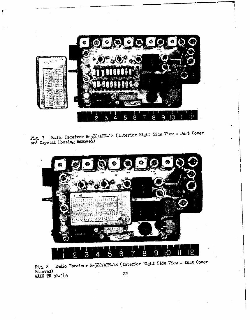
Fig. 7 Radio Recei.ver '-0322/AR7-1S (Interior Ri~ght Sid~e View - Dus~t Cover
and Crystal Housing Senmved)
Fig. g Radio Receiver R-322/AR\-2.S (Interior Fight Side View - Dlust Cover
Rexroved)OWfl TE 52-146 22
0)
0 ..
00u0
D-
WIADC TR 52-1146 23
DISTRIBUTION LIST FOR WADC TECHNICAL REPORT 52-21-.6
Cys Activities at W-PAFB Cys Activities
16 WCENS-3 1 Washington AF Eng Field OfficeRoom 49.9, Main Navy Bldg.
2 WCRR (For Rand Corp.) Department of the NavyWashington 25, D. C.
1 WCAPP1 AF Engineering Field Represent-
4 BAGR-CD, Mrs. D. Martin ativeCode 1110, Naval Res Lab
2 DSC-SA Washington 25, D. C.ATTN: Lt Col M. N. Abramovich
3 W1EO1 Commanding General
Dept. of Defense Activities Air Proving Ground CommandOther Than Those at W.-PAFB ATTN: Class. Tech. Data Br.,
D/OIAir Force Eglin Air Force Base, Florida
1 Director of Research and Development 1 DirectorHeadquarters, USAF Air University LibraryWashington 25, D. C.
Maxwell Air Force Base, Alabama1 Commanding General
Air Research and Development Command I Director of Communications andATTN.* RDOL ElectronicsP. 0. Box 1395 Air Defense CommandBaltimore 3, Maryland Ent Air Force Base
ATTN: AC&W Coordinating Divisioh1 Commanding General Colorado Springs, Colorado
Rome Air Development CenterATTN: ENR 1 Commanding GeneralGriffiss Air Force Base Strategic Air CommandRome, New York ATTN: Operations Analysis Office
Offutt Air Force Base, Nebraska1 Commanding General
Air Force Cambridge Research Center NavyATTN: ERR230 Albany Street Chief of Naval ResearchCambridge 39, Massachusetts Department of the Navy
Washington 25, D. C.1 Commanding General 6 ATTN: Planning Div., Code N-LO2
Tactical Air Command 1 ATTN: Elec. Section, Code 2427Langley AF Base, Virginia
WADe Th 52-1246 24
DISTRIBUTION LIST FOR WADC T[ECHNICAL REPORT 52-146
Cys Activities Cys Activities
1 Chief, Bureau of Ordnance ArmyDepartment of the INavyATTN: Code AD-3 2 Commanding OfficerWashington 25, D.C. Signal Corps Eng Laboratory
ATTN: Technical Reports Library1 Chief of Naval Operations Fort iionmouth, New Jersey
Department of the NavyATTN: OP-42-B2 Research and' Development BoardWashington 25, D.C.
2 Research and Development Board1 Chief, Bureau of Ships Library Branch, Info. Offices
Department of the Navy ATTN: C.R. Flagg, Rm. 3DlO4lATTN: Technical Data Section The PentagonWashington 25, D.C. Washington L5, D.C.
1 Director Special krojectsU.S. Naval Research LaboratoryATT11: Technical Data Section 1 Document RoomWashington 25, D.C. Project LINCOLN
Mlass. Inst. of Technology1 CO & Director P.O. Box 390
U.S. Navy Electronics Laboratory Cambridge 39, Mass.San Diego 52, California ATTN: Ethel R. Branz
1 Commander Other Activities (U.S. Government)U.S. Naval Ordnance Test StationInyokern 1 Civil Aeronautics AdministrationChina Lake, California Technical Development and
Evaluation Center
1 Superintendent P.O. Box 5767United States Naval Academy Indianapolis 21, IndianaPost Graduate SchoolAnnapolis, M-aryland
1 Commanderb.S. Naval Air Development CenterATTN: Electronics LaboratoryJohnsville, Pennsylvania
1 CommanderU.S. Naval Ordnance LaboratorySilver Spring 19, M1aryland
WADC TR 52-146 25