Evaluation Kit Picosecond Fiber Laser PSFL1030. 2 /46 Instruction manual PSFL1030 _ .de 1. General...
46
p. 1/46 Instruction manual PSFL1030 _ www.batop.de Evaluation Kit Picosecond Fiber Laser PSFL1030 (REV. 3.5 2018-09-07) Table of contents 1. General description ........................................................................................................................2 2. Needed additional equipment .........................................................................................................2 3. Laser safety ...................................................................................................................................3 4. Parts of the evaluation kit ...............................................................................................................3 4.1 Evaluation kit PSFL1030 list of components ........................................................................ 3 4.2 Information on operation diode laser DL-975-100 ................................................................. 6 4.3 SAM-1030-32-1ps data .......................................................................................................12 4.3.1 Main SAM data...................................................................................................................12 4.3.2 Discussion of SAM parameters...........................................................................................12 4.4 Spectral reflection and transmission of FBG ........................................................................14 4.5 Transmission of the PM filter WDM......................................................................................16 4.6 PHS – Passive heat sink for fiber coupled SAM ...................................................................17 4.7 Spectral reflectance of the 100 % mirror M-PM980-XP-FC/APC ..........................................18 5. Experiments ................................................................................................................................. 19 5.1 Fiber end cleaning and arrangement ...................................................................................19 5.2 Pump laser diode output power ...........................................................................................20 5.3 Luminescence and gain of Yb-doped fiber PM-YSF-HI ........................................................22 5.3.1 Experiment .........................................................................................................................22 5.3.2 Discussion of the measured results ....................................................................................24 5.4 Continuous wave laser ........................................................................................................26 5.5 Picosecond laser, WDM coupler outside the cavity .............................................................. 28 5.5.1 Experiments .......................................................................................................................28 5.5.2 Discussion of the measured results ....................................................................................34 5.6 Picosecond laser, WDM coupler inside the cavity ................................................................ 41 5.6.1 Experiment .........................................................................................................................41 5.6.2 Discussion of the measured results ....................................................................................42 5.7 Picosecond oscillator + amplifier..........................................................................................43 5.8 FBG transmittance ..............................................................................................................45 6. Ordering information..................................................................................................................... 46 7. Support ........................................................................................................................................ 46
Transcript of Evaluation Kit Picosecond Fiber Laser PSFL1030. 2 /46 Instruction manual PSFL1030 _ .de 1. General...

p. 1/46 Instruction manual PSFL1030
_
www.batop.de
Evaluation Kit Picosecond Fiber Laser PSFL1030
(REV. 3.5 2018-09-07) Table of contents 1. General description ........................................................................................................................2 2. Needed additional equipment .........................................................................................................2 3. Laser safety ...................................................................................................................................3 4. Parts of the evaluation kit ...............................................................................................................3
4.1 Evaluation kit PSFL1030 list of components ........................................................................ 3 4.2 Information on operation diode laser DL-975-100 ................................................................. 6 4.3 SAM-1030-32-1ps data .......................................................................................................12
4.3.1 Main SAM data...................................................................................................................12 4.3.2 Discussion of SAM parameters...........................................................................................12
4.4 Spectral reflection and transmission of FBG ........................................................................14 4.5 Transmission of the PM filter WDM......................................................................................16 4.6 PHS – Passive heat sink for fiber coupled SAM...................................................................17 4.7 Spectral reflectance of the 100 % mirror M-PM980-XP-FC/APC ..........................................18
5. Experiments.................................................................................................................................19 5.1 Fiber end cleaning and arrangement ...................................................................................19 5.2 Pump laser diode output power ...........................................................................................20 5.3 Luminescence and gain of Yb-doped fiber PM-YSF-HI ........................................................22
5.3.1 Experiment.........................................................................................................................22 5.3.2 Discussion of the measured results ....................................................................................24
5.4 Continuous wave laser ........................................................................................................26 5.5 Picosecond laser, WDM coupler outside the cavity ..............................................................28
5.5.1 Experiments .......................................................................................................................28 5.5.2 Discussion of the measured results ....................................................................................34
5.6 Picosecond laser, WDM coupler inside the cavity ................................................................41 5.6.1 Experiment.........................................................................................................................41 5.6.2 Discussion of the measured results ....................................................................................42
5.7 Picosecond oscillator + amplifier..........................................................................................43 5.8 FBG transmittance ..............................................................................................................45
6. Ordering information.....................................................................................................................46 7. Support ........................................................................................................................................46

p. 2/46 Instruction manual PSFL1030
_
www.batop.de
1. General description The evaluation kit PSFL1030 allows the realization of different picosecond fiber laser configurations using a saturable absorber mirror (SAM) as nonlinear optical device for passive mode-locking and standard fibers in the laser cavity. The active fiber is Yb doped. The fiber laser design can be changed easily to study the influence of certain elements on the laser output signal. The discussion of experimental results supports the understanding of important phenomena in a passive mode-locked Yb-doped fiber laser. The user gets the needed knowledge to construct its own ps laser setup. The following fiber laser setups can be realized with the evaluation kit PSFL1030:
passive mode-locked ps fiber laser with a saturable absorber mirror (SAM) ps oscillator + fiber amplifier combination continuous wave fiber laser at 1030 nm wavelength amplified spontaneous emission (ASE) broadband emitter.
Your comments Comments and proposals for improvement the evaluation kit PSFL1030 with respect to hardware configuration, experimental results and their discussion are very welcome. You can help us to improve this evaluation kit and to support the distribution of knowledge about passively mode-locked fiber lasers and to extend their use in different applications. Please send your comments to [email protected]
2. Needed additional equipment The evaluation kit contains all components to build and run a picosecond fiber laser. To measure the laser output parameters besides the evaluation kit PSFL1030 the following additional equipment is needed for the proposed laser experiments: Item Symbol Description
1 laser safety goggles with OD3+ for 975 nm
2
Fast photo diode to trace the time dependent laser output signal
3
Optical power meter, 100 mW to measure the average laser output
4
Oscilloscope 200 MHz for measurement of the photodiode output signal
5 PC or Laptop for controlling DL-975-100 Windows 7 or higher; FTDI drivers, Microsoft Visual C++ 2015, LabVIEW Runtime Engine 2016, one free USB port
6 Fiber scope for visual inspection of connector end face, for instance Thorlabs FS200
7 Optional equipment: OSA – optical spectrum analyzer
8 Optional equipment: Autocorrelator for pulse duration measurement
PD
PM
OSA

p. 3/46 Instruction manual PSFL1030
_
www.batop.de
3. Laser safety
_
Class 3b Laser
Always wear appropriate laser safety goggles with OD3+ for 975 nm. Recommendation: Protector 008.T0004.0 (OD4+ for 960 – 1400 nm) from LaserVision
Be aware of hazardous and invisible laser light which can escape from
fiber ends.
4. Parts of the evaluation kit
4.1 Evaluation kit PSFL1030 list of components The evaluation kit PSFL1030 consists of the following components:
Item Qty Part No. and symbol Description
1 1 SAM-1030-32-1ps-FC/APC-PM980-XP
Saturable absorber mirror, wavelength 1030 nm, absorptance 32 %, relaxation time 1 ps, mounted on a 15 cm long fiber PM980-XP with FC/APC connector
2 1 PHS Passive heat sink for fiber coupled SAM
3 1 PM-YSF-HI-20-FC/APC
Panda-Type Yb-doped PM fiber, 20 cm long, FC/APC connectors
4 1 PM-YSF-HI-30-FC/APC
Panda-Type Yb-doped PM fiber, 30 cm long, FC/APC connectors
5 1 FBG-1030-0.8-87-PM980-XP-100-FC/APC
PM Fiber Bragg grating, wavelength 1030 nm, spectral width 0.8 nm, maximum reflectance 87 %, 100 cm fiber PM980-XP, FC/APC connectors
6 1 PMFWDM-1x2-T1030/R980-FC/APC PM filter WDM, pass band wavelength 1010 - 1080 nm,
SAM
Yb
Yb
FBG
p. 4/46 Instruction manual PSFL1030
_
www.batop.de
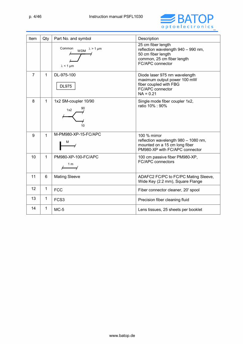
Item Qty Part No. and symbol Description
25 cm fiber length reflection wavelength 940 – 990 nm, 50 cm fiber length common, 25 cm fiber length FC/APC connector
7 1 DL-975-100
Diode laser 975 nm wavelength maximum output power 100 mW fiber coupled with FBG FC/APC connector NA = 0.21
8 1 1x2 SM-coupler 10/90
Single mode fiber coupler 1x2, ratio 10% : 90%
9 1 M-PM980-XP-15-FC/APC
100 % mirror reflection wavelength 980 – 1080 nm, mounted on a 15 cm long fiber PM980-XP with FC/APC connector
10 1 PM980-XP-100-FC/APC
100 cm passive fiber PM980-XP, FC/APC connectors
11 6 Mating Sleeve ADAFC2 FC/PC to FC/PC Mating Sleeve, Wide Key (2.2 mm), Square Flange
12 1 FCC Fiber connector cleaner, 20' spool
13 1 FCS3 Precision fiber cleaning fluid
14 1 MC-5 Lens tissues, 25 sheets per booklet
WDM Common > 1 µm
< 1 µm
90
10
1x2
M
1 m
DL975
p. 5/46 Instruction manual PSFL1030
_
www.batop.de
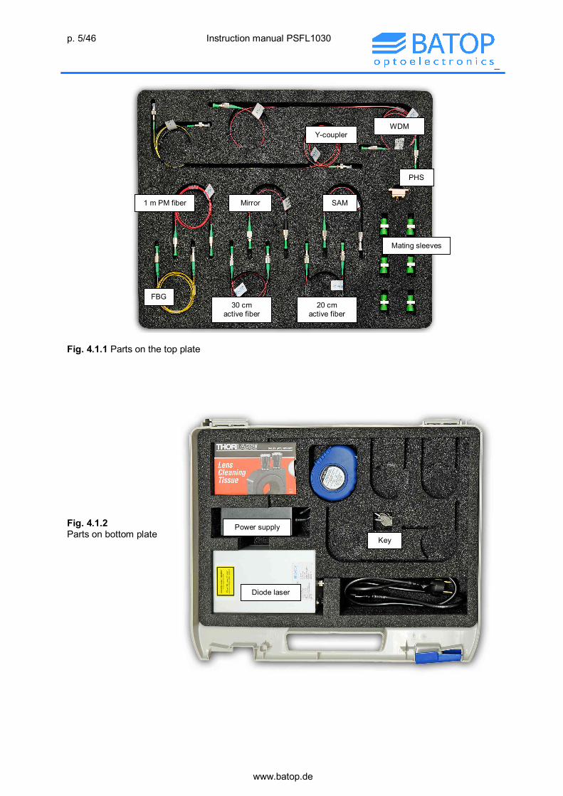
Fig. 4.1.1 Parts on the top plate Fig. 4.1.2 Parts on bottom plate
PHS
SAM Mirror 1 m PM fiber
Y-coupler WDM
30 cm active fiber
FBG 20 cm
active fiber
Mating sleeves
Diode laser
Power supply Key

p. 6/46 Instruction manual PSFL1030
_
www.batop.de
4.2 Information on operation diode laser DL-975-100 Diode laser DL-975-100 Emission wavelength = 975 nm Maximum output power Pout = 100 mW Fiber connector: FC/APC Power supply: 12 V Control software: either Console software or LabVIEW software General information The DL-975 comes with some additional equipment:
- Power supply (Input 110V – 230V 50Hz; Output 12V DC, 5A) - USB Cable - Key
To work with the DL-975 a PC or Laptop with Windows 7 or higher, a free USB-Port (USB 2.0 is sufficient), FTDI drivers and Microsoft Visual C++ 2015 is required. The FTDI drivers are installed automatically by Windows if the PC is connected to the internet. For manual downloading and installing of the FTDI Drivers please refer http://www.ftdichip.com/Drivers/D2XX.htm. The LabVIEW control software needs the LabVIEW runtime engine 2016, which can be found on the homepage of National Instruments (www.ni.com). If the DL-975 is connected the first time to a PC, Windows will install the FTDI drivers. This could take several minutes. Controlling of the DL-975 should be done by control software, either by console software or by LabVIEW software (See chapter controlling software). It is also possible to switch on the DL-975 by pressing the black ‘Laser’ button on the front side without a connection to PC. After each power down the pump current is set to 0 mA. The following pictures show the front and back panel of the DL-975. The connector for the power supply and the USB port are located on the back panel. On the front panel are the main controlling interfaces like
- Key lock switch to turn on main power - state LED’s - Laser button - FC/APC fiber connector (marked with ‘LASER APERTURE’)
Fig. 4.2.1 back panel with power supply connector an USB port
Fig. 4.2.2 front panel with key lock switch, FC/APC fiber connector, Laser
button and LED’s

p. 7/46 Instruction manual PSFL1030
_
www.batop.de
The three LEDs on the front side of the DL-975 indicate the state. The following table shows the possible LED states. LED Description What to do Green Power Green flash Temperature Warning
T>45°C inside the case Cool down the module (shut off or cool the case)
Orange Laser on Green and Orange flash together
Temperature Limit T>50°C inside the case
Cool down the module (shut off or cool the case)
Red Error Try to restart. Have a look at the status, if DL-975 is connected to PC.
Green and orange flash alternately
Configuration error Have a look at the status, if DL-975 is connected to PC. Contact support.
On the bottom of the DL-975 are 4 holes (metric thread M4), which can be used to fix the module on an optical table for example. See the figure 4.2.3 for the details of the holes.
Fig. 4.2.3 Dimension of DL-975 and position of mounting holes
Operation of the DL-975 should be done as follows:
- put the DL-975 on a dry and clean surface - connect the power supply to the DL-975 - connect the DL-975 to the PC via USB-Cable - Make sure the PC is switched on - Switch on the DL-975 with the key - Start control software
IMPORTANT: If you switch on the DL-975 before connecting it to PC, you have to restart the
DL-975. IMPORTANT: It is not possible to reconnect the USB cable or restart the PC without restarting
the DL-975.
p. 8/46 Instruction manual PSFL1030
_
www.batop.de
Controlling software Attention To avoid possible damages of parts of the set up by turning on the laser at a high
pump power, it is recommended to set the pump power to 0 mA. This is important due to the reason that the value of current is not shown before turning on laser operation.
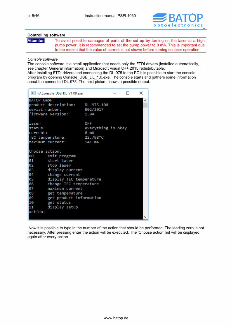
Console software The console software is a small application that needs only the FTDI drivers (installed automatically, see chapter General information) and Microsoft Visual C++ 2015 redistributable. After installing FTDI drivers and connecting the DL-975 to the PC it is possible to start the console program by opening Console_USB_DL_1.0.exe. The console starts and gathers some information about the connected DL-975. The next picture shows a possible output.
Now it is possible to type in the number of the action that should be performed. The leading zero is not necessary. After pressing enter the action will be executed. The ‘Choose action’ list will be displayed again after every action.

p. 9/46 Instruction manual PSFL1030
_
www.batop.de
The following table lists the several actions with an explanation. Action number
Description Explanation
00 Exit program Closes the program; Laser will NOT be shut off 01 Start Laser Switches the Laser on. It is the same like pressing the black Laser
button. 02 Stop Laser Switches the Laser off. It is the same like pressing the black Laser
button. 03 Display current Shows the actual current on the Laser diode. If the Laser is
switched off, 0 mA will be displayed. 04 Change current Changes the operating current of the Laser diode. The current can
be changed from 0 mA to maximum current with a step size of 1 mA
05 Display TEC temperature Shows the actual target temperature of the TEC of the Laser diode.
06 Change TEC temperature Changes the actual target temperature of the TEC of the Laser diode. The temperature can be changed from 15°C to 35°C with a step size of 0,001°C
07 maximum current Shows the maximum operating current of DL-975 08 Get temperature Shows the actual temperature inside the case. It is NOT the
temperature of the Laser diode 09 Get product information Shows the product information: product description, serial
number, firmware 10 Get status Shows the actual state of the DL-975. For more information see
chapter status overview 11 Display setup Shows the actual information like shown at start up

p. 10/46 Instruction manual PSFL1030
_
www.batop.de
The next picture shows the output of the console after performing action 1 ‘start laser’.

p. 11/46 Instruction manual PSFL1030
_
www.batop.de
LabVIEW software Alternatively it is possible to control the DL-975 with a LabVIEW program. The LabVIEW RunTimeEngine 2016 (RTE2016) is required for this program. The RTE2016 can be found on the homepage of National Instruments (www.ni.com). After connecting the DL-975 to the PC start LabView_USB_DL_1.0.exe. At startup the program shows the actual pump current and the case temperature. For controlling the pump laser just use the specified buttons. If you want to change the pump for example just type in the pump current in the box next to the ‘change’ button and then press ‘change’ button or simply turn the rotation knob. The behavior and the limits of the parameters are equal to the console software. The next picture shows the front panel of the LabVIEW program.
LabVIEW program
1. Switch on /off 2. Change pump
current 3. Read
temperature and status
4. Product specification
5. Firmware
6. LabVIEW RTE 2016 required
LabVIEW program Status overview Status Code Description What to do LED 00 Status ok 01 High Temperature Cool down the module
(shut off or cool the case)
Green and Orange flash together
02 Temperature warning Cool down the module (shut off or cool the case)
Green flash
04 Init read fail Contact support Green and orange flash alternately
08 Checksum fail Contact support Green and orange flash alternately
10 Data Storage error 80 Watchdog Crash Try to restart or contact
support Red
ff Critical error Try to restart or contact support
Red

p. 12/46 Instruction manual PSFL1030
_
www.batop.de
4.3 SAM-1030-32-1ps data
4.3.1 Main SAM data The saturable absorber mirror (SAM) serves as nonlinear optical device to start and maintain continuous wave (cw) mode-locking. The main parameters of the SAM-1030-32-1ps are: Laser wavelength = 1030 nm Absorption A = 32 % at 1030 nm Saturation fluence Fsat = 0.3 J/m2 Relaxation time = 1 ps
Figure 4.3.1 Low intensity spectral reflectance of SAM-1030-32-1ps
Figure 4.3.2 Relaxation of SAM-1030-32-1ps in a pump-probe measurement. The main part of the relaxation shows a time constant of 1.1 ps.
4.3.2 Discussion of SAM parameters The SAM consists of a mirror for the laser wavelength and an absorber layer in front of this mirror. The reflectance R = 1 - A of the SAM is determined by the absorption A of the absorber layer because the transmission though the mirror is zero. The absorber consists of thin layers of a semiconductor material with band gap energy Eg somewhat smaller then the photon energy h of the laser light. Near the band gap the electronic density of states in the absorber is small and already a few absorbed photons can partially saturate the absorber, increase the SAM reflectance and therefore decrease the loss in the laser cavity.

p. 13/46 Instruction manual PSFL1030
_
www.batop.de
Besides the decrease of absorption with increasing illumination also the influence of the heating in the absorber must be considered because the absorption increases significantly with temperature Saturation Taking into account the typical lateral intensity distribution on the SAM surface according to a Gaussian beam the nonlinear reflectance of the SAM can be described in case of a long relaxation time as follows:
satF
Fsat
0 e1F
FA1R
(4.3.1) with the parameters A0 – low intensity absorption F - pulse fluence Fsat – saturation fluence In a laser cavity with an optical amplifier and a SAM a small increase of the amplified luminescence light can partially saturate the absorber and increase the SAM reflectance. This results in increasing amplitude of the fluctuation and a formation of a pulse during several round trips in the cavity. The periodic saturation of the SAM during the round trip of the pulse locked all luminescence modes with different wavelengths together to a short pulse with a broad spectrum. This process is called mode-locking and results in a single pulse in the laser cavity with a fixed repetition rate given by the cavity length and the speed of light in the cavity. This is equivalent to the phase condition in a continuous wave laser, where the cavity length determined the lasing wavelength. Two photon absorption - TPA
Two photon absorption (TPA) must be considered in case of short pulses, especially if the pulse duration tP is < 1 ps. But also in case of puse duration of a few ps it must be considered because it decreases the SAM modulation depth R.
The two-photon absorption ATPA increases the total absorption as follows:
PTPA t
dFdIA
(4.3.2)
With β - two-photon absorption coefficient I - pulse intensity d - absorber layer thickness F - pulse fluence tP - pulse duration.
The integration of the time dependent intensity I(t) over the pulse duration tP results in the pulse fluence F. Therefore the pulse fluence can be approximated as F ~ I · tP. The two-photon absorption coefficient β is a material dependent parameter. For GaAs the value is β = 2.5·10-10 m/W.
SAM saturation including TPA The dependency of the SAM reflectance on pulse fluence F including the TPA can be written as
P
FF
sat0 t
dFe1F
FA1)F(R sat
(4.3.3) The TPA decreases the reflectance for high pulse fluence and short pulses. For a SAM useful in a fiber laser the typical thickness of the absorber layer including the top part of the AlAs/GaAs Bragg mirror is about d ~ 2 µm. The typical pulse duration using the fiber laser evaluation kit is ~ 5 ps. In this case the TPA is not important. The figure below shows the saturation curve.

p. 14/46 Instruction manual PSFL1030
_
www.batop.de
Figure 4.3.4 Saturation curve R(F) in a linear (left) and logarithmic scale (right) for SAM-1030-32-1ps according to equation (3). R is the modulation depth and Ans is the non-saturable loss. The pulse energy EP is calculated using EP= r2F with r = 3.2 µm (mode field radius).
The TPA causes a roll-over of the saturation curve before complete saturation. Therefore the modulation depth R is smaller then the absorption A0. The difference Ans = A0 - R is called non-saturable loss.
4.4 Spectral reflection and transmission of FBG The fiber Bragg grating FBG-1030-0.8-87-FC/APC-PM980-XP serves as wavelength locker at the maximum reflectance of 1030 nm wavelength. The main parameters are: Maximum reflectance wavelength 0 = 1030 nm Reflectance at 0 R0 = 0.87 Reflectance spectral width FBG = 0.8 nm (Full width at half maximum) Figure 4.4.1 Measured spectral transmission of the FBG
The FBG is used as output coupler in the ps laser setup. As a result of nonlinear spectral pulse broadening in the optical fiber at high optical intensity the spectral pulse width depends on the pulse

p. 15/46 Instruction manual PSFL1030
_
www.batop.de
fluence. Therefore the transmittance of the FBG depends on the pulse fluence F or spectral pulse width . To calculate the FBG transmittance T on the pulse width the FBG transmittance can be approximated as
2
20 )(2ln4
01)(1)( FBGeRRT
(4.4.1) with the parameters R0, 0, and FBG given above. The spectral intensity distribution of a Gaussian optical pulse can be written as
2
20 )(2ln4
0 eI)(I
(4.4.2)
Here I0 is the pulse intensity at 0 and is the full width at half maximum spectral pulse distribution. Using (4.4.1) and (4.4.2) the wavelength integrated FBG transmission T in dependence on the Gaussian pulse width can be calculated as
2
FBG
0
0
0
1
R1d)(I
d)(R1)(I)(T
(4.4.3)
This dependency is shown in figure 4.4.2 below. The transmission increases with increasing spectral pulse width from 1-R0 = 0.13 to about 0.8 at a spectral width of 3 nm. Fig 4.4.3 Calculated total transmission of the FBG in dependency on the spectral width of a Gaussian pulse

p. 16/46 Instruction manual PSFL1030
_
www.batop.de
4.5 Transmission of the PM filter WDM
The polarization maintaining filter wavelength division multiplexer PMFWDM-1x2-T1030/R980 can be used to couple the 980 nm pump light into the laser cavity. The pump light is reflected via a dichroitic mirror from the “Reflect” fiber into the “Common” fiber. For the 1030 nm laser wavelength the mirror has a high transmission, so that for this wavelength the “Common” fiber is connected with the “Pass” fiber. The “Reflect” fiber is marked with a black line. Measured transmission between Reflect and Common (Low Pass) TLP = 0.78 Measured transmission between Pass and Common (High Pass) THP = 0.75 Figure 4.5.1 Measured spectral transmittance of the wavelength division multiplexer PMFWDM-1x2-T1030/R980
WDM Common > 1 µm
< 1 µm

p. 17/46 Instruction manual PSFL1030
_
www.batop.de
4.6 PHS – Passive heat sink for fiber coupled SAM
Figure 4.6.1 Fiber coupled SAM inserted into the passive heat sink
The SAM chip is fixed on the fiber end. Thermal contact between the SAM and the copper baseplate is made with a small amount of a thermal conducting paste. The copper baseplate can be placed on a larger metal plate with good thermal conductivity. Assembly instructions
(note: during shipment the connector of the fiber patch cable is not plugged into the passive heat sink) A small portion of a heat conducting paste should be applied to the lower side of the RSAM chip (e.g. by the use of a utility, like a needle or a similar tool) mounted on the end face of the FC/PC connector. Do not use too much of the conducting paste! For example see figure 4.6.2. This procedure ensures a good thermal contact between the SAM chip and the copper heat sink.
Carefully insert the FC/PC plug with the chip in the female connector at the top plate. Smoothly tighten the coupling ring until the chip touches the copper surface of the base plate. Do not overtighten the connector, this may damage the chip!
Figure 4.6.2: SAM chip on FC/PC connector end face
Figure 4.6.3: same connector as Figure 4.6.2 with heat conducting paste

p. 18/46 Instruction manual PSFL1030
_
www.batop.de
4.7 Spectral reflectance of the 100 % mirror M-PM980-XP-FC/APC Reflectance at 1030 nm R = 0.995 Fiber type PM980-XPFiber length l = 15 cm Connector FC/APC Figure 4.7.1 Spectral reflectance of the fiber coupled 100 % mirror M-PM980-XP-15-FC/APC
Figure 4.6.4: FC/PC connector inserted in the passive heat sink
Figure 4.6.5: the SAM chip is in contact with the base plate, stop tighten the coupling ring

p. 19/46 Instruction manual PSFL1030
_
www.batop.de
5. Experiments
5.1 Fiber end cleaning and arrangement Cleaning of fiber connectors For cleaning of fiber connectors please use a soft and lint-free lens tissue. Best cleaning results are achieved, if you use simultaneously a small amount of ethanol or similar cleaning solvents. For cleaning gently wipe with the ferrule end face over the soaked tissue writing some “figure 8” loops. If the alignment of the ferrule is correct, the end face must be smoothly slide over the tissue surface. For FC/APC connectors, please be sure to tilt the ferrule by approx. 8 degree. Please check the end face of the ferrule after cleaning using a fiber scope. The whole surface must be free from particles or solvent residuals as shown in the following pictures.
Dirty ferrule end face Clean ferrule end face Figure 5.1.1: Microscope images of a dirty (left) and a clean (rifgt) fiber end In general, please avoid plugging the connectors more than necessary, because the surface quality degrades with each connection process. Aligment of connectors Because the mode field diameter in the fiber is only ~ 6.5 µm already a very small misalignment of ~ 0.1 µm between the fiber cores in a mating sleeve can cause a substantial coupling loss. Therefore it makes sense to touch the connectors slightly to maximise the laser output signal by minimizing the coupling losses in the fiber connections. A too strong tighten of the FC/APC connector can result in a small shift of the core axes and an additional coupling loss. Fiber laser layout The schematic shown in each chapter helps to connect the fiber parts of the evaluation kit in a right way. The kit contains mainly polarization maintaing fibers to promote the propagation of optical pulses with defined polarization orientation and to support a stable laser output. Please avoid random twisting of the fiber. A simple way to avoid fiber twisting is to make a cavity layout with fibers arranged in a straight line.
fiber
particles
ceramic ferrule
p. 20/46 Instruction manual PSFL1030
_
www.batop.de
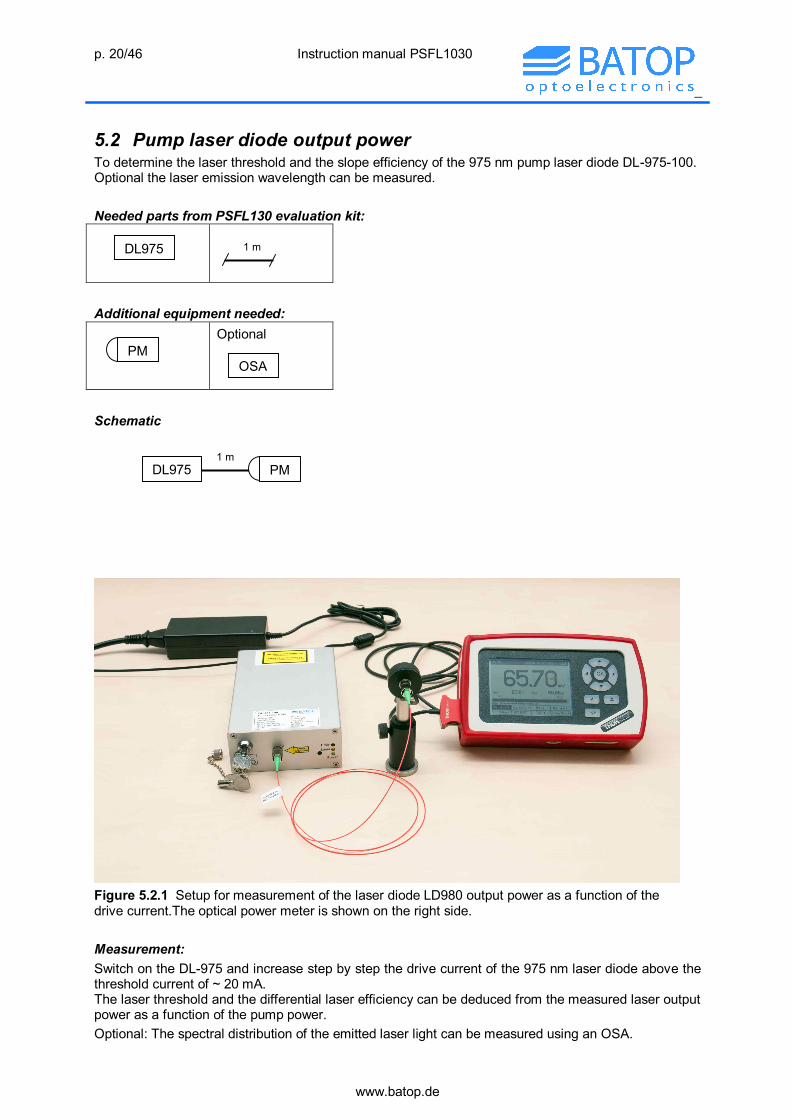
5.2 Pump laser diode output power To determine the laser threshold and the slope efficiency of the 975 nm pump laser diode DL-975-100. Optional the laser emission wavelength can be measured. Needed parts from PSFL130 evaluation kit:
Additional equipment needed:
Optional
Schematic
Figure 5.2.1 Setup for measurement of the laser diode LD980 output power as a function of the drive current.The optical power meter is shown on the right side. Measurement: Switch on the DL-975 and increase step by step the drive current of the 975 nm laser diode above the threshold current of ~ 20 mA. The laser threshold and the differential laser efficiency can be deduced from the measured laser output power as a function of the pump power. Optional: The spectral distribution of the emitted laser light can be measured using an OSA.
PM OSA
1 m DL975 PM
1 m DL975

p. 21/46 Instruction manual PSFL1030
_
www.batop.de
Measurement results Figure 5.2.2 Laser output power Pout versus pump current IP
The slope efficiency of the laser diode can be calculated using the relation
chVes
hVes
(5.2.1) With s – slope of the measured Pout – IP characteristic e – charge of an electron ~ 1.610-19 As V – forward voltage of the laser diode ~ 2 V – laser wavelength ~ 98010-9 m h - Planck constant ~ 6.6310-34 VAs2 c – speed of light ~ 3108 m/s = c/ - laser frequency ~ 31014 Hz The slope efficiency of the pump laser can be calculated to = 0.66. Figure 5.2.3 Spectral power distribution of the emitted pump light for three different pump currents IP. The emission wavelength of the pump diode is fixed to about 975 nm because the laser cavity is stabilized with a fiber Bragg grating.
p. 22/46 Instruction manual PSFL1030
_
www.batop.de
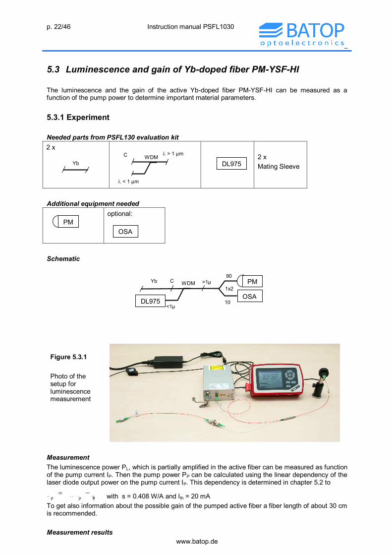
5.3 Luminescence and gain of Yb-doped fiber PM-YSF-HI The luminescence and the gain of the active Yb-doped fiber PM-YSF-HI can be measured as a function of the pump power to determine important material parameters. 5.3.1 Experiment Needed parts from PSFL130 evaluation kit 2 x
2 x Mating Sleeve
Additional equipment needed
optional:
Schematic
Figure 5.3.1 Photo of the setup for luminescence measurement
Measurement The luminescence power PL, which is partially amplified in the active fiber can be measured as function of the pump current IP. Then the pump power PP can be calculated using the linear dependency of the laser diode output power on the pump current IP. This dependency is determined in chapter 5.2 to
)II(*sP thPP with s = 0.408 W/A and Ith = 20 mA
To get also information about the possible gain of the pumped active fiber a fiber length of about 30 cm is recommended. Measurement results
WDM C > 1 µm
< 1 µm
PM OSA
1x2
90 Yb
<1µ DL975 10
C WDM PM >1µ
OSA
DL975 Yb

p. 23/46 Instruction manual PSFL1030
_
www.batop.de
Fig. 5.3.2 Amplified luminescence power PL of the 30 cm long Yb-doped fiber as a function of pump power PP. The luminescence power PL is calculated from the measured luminescence considering the WDM transmission THP = 0.8.
Fig. 5.3.3 Spectral luminescence after transmission through the WDM filter from Common to Pass, measured with an optical spectrum analyzer (OSA)
Fig. 5.3.4 Spectral transmission of the Yb-doped fiber, measured with an optical spectrum analyzer (OSA). The signal source is the 30 cm long pumped PM-YSF-HI with the emission spectrum shown in figure 5.3.3. The decreasing signal/noise ratio for longer wavelengths is the result of decreasing luminescence light in this region.

p. 24/46 Instruction manual PSFL1030
_
www.batop.de
5.3.2 Discussion of the measured results Spectral luminescence The WDM filter coupler cuts light with shorter wavelengths then ~ 1010 nm. Therefore the pump light is not measured. The luminescence maximum is in the range between 1020 nm and 1030 nm. Luminescence amplitude and gain The pump power saturates a certain length of active fiber L. The saturated fiber length is proportional to the pump power PP. The result is twofold:
- The saturated fiber emits a part of its luminescence light into the fiber with the numerical aperture NA = 0.11.
- The guided luminescence light is amplified in the saturated part of the fiber. The amplified luminescence light on the fiber end can be calculated as follows:
L
LgxgL )(e
gq=dxeq=P
0
1 (5.3.1)
Here q is the luminescence power per fiber length dx and g is the gain coefficient. The saturated fiber length L is proportional to the pump power PP with a factor cP and can be written as L = cPPP. Using this relation the above equation can be rewritten to
)P(egq)P(e
PL
gq)P(e
gq=P PPg
P
PPPg
PP
PPgL 111
(5.3.2)
with
gg
PLc PP
PP
(5.3.2) From the measurement in figure 5.3.2 above it can be deduced, that the amplified luminescence power does not increase further exponential above a pump power of 22 mW in a 30 cm long active fiber. From this observation the coefficient cP can be determined to cP = 30cm/22mW = 1.36 cm/mW = 13.6 m/W. This means that in case of low optical signal a pump power of 0.73 mW is needed to saturate a fiber length of 1 cm. From the measured slope qP = 2.9810-4 without amplification of the luminescence light the luminescence power q in the spectral range around 1030 nm per pumped fiber length can be deduced to q = qP /cP = 21.9 µW/m. If the whole pump power PP would be converted into luminescence around 1030 nm without any loss and emitted into the full solid angel 4, then the expected luminescence power in one fiber direction can be estimated with the solid angle captured by the guided wave in the fiber. The aperture angle inside the fiber with the numerical aperture NA is given by the relation NA = nsin. Because the fiber aperture is small, the solid angle can be estimated to
222
n2NA4
n2NAsin4
2sin4
(5.3.3) The difference between the photon energy of pump light EP and luminescence light at 1030 nm EL must be considered in the total energy balance. The expected luminescence light per saturated active fiber length can be estimated by
cLr
λλ
nNA=Pr
EE
πΩ=P L
L
PPL
P
LL
2
24 (5.3.4)
The ratio rL of the luminescence power around 1030 nm and the total luminescence power can be estimated to r ~ 1/3. With the numerical aperture NA = 0.11 of the fiber, the refractive index n = 1.46 of the fiber core, the pump wavelength P= 980 nm, the luminescence wavelength L= 1030 nm the luminescence light per meter in one fiber direction can be estimated to 30 µW/m. The difference
p. 25/46 Instruction manual PSFL1030
_
www.batop.de
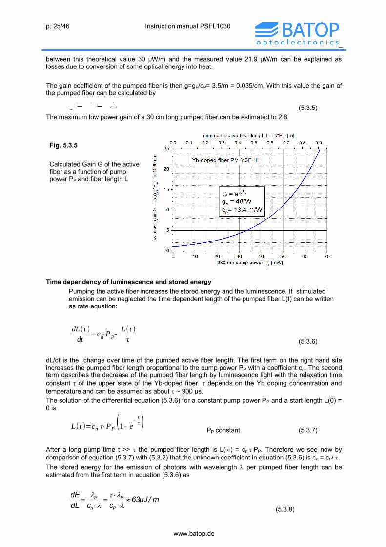
between this theoretical value 30 µW/m and the measured value 21.9 µW/m can be explained as losses due to conversion of some optical energy into heat. The gain coefficient of the pumped fiber is then g=gP/cP= 3.5/m = 0.035/cm. With this value the gain of the pumped fiber can be calculated by
PP PgLgeeG
(5.3.5) The maximum low power gain of a 30 cm long pumped fiber can be estimated to 2.8. Fig. 5.3.5 Calculated Gain G of the active fiber as a function of pump power PP and fiber length L
Time dependency of luminescence and stored energy
Pumping the active fiber increases the stored energy and the luminescence. If stimulated emission can be neglected the time dependent length of the pumped fiber L(t) can be written as rate equation: dL( t )dt
=cn ⋅PP −L( t )τ (5.3.6)
dL/dt is the change over time of the pumped active fiber length. The first term on the right hand site increases the pumped fiber length proportional to the pump power PP with a coefficient cn. The second term describes the decrease of the pumped fiber length by luminescence light with the relaxation time constant of the upper state of the Yb-doped fiber. depends on the Yb doping concentration and temperature and can be assumed as about ~ 900 µs. The solution of the differential equation (5.3.6) for a constant pump power PP and a start length L(0) = 0 is
L( t )=cn ⋅ τ ⋅ PP ⋅ (1 − e −tτ )
PP constant (5.3.7) After a long pump time t >> the pumped fiber length is L() = cnPP. Therefore we see now by comparison of equation (5.3.7) with (5.3.2) that the unknown coefficient in equation (5.3.6) is cn = cP/ . The stored energy for the emission of photons with wavelength per pumped fiber length can be estimated from the first term in equation (5.3.6) as
m/µJ63
ccdLdE
P
P
n
P
(5.3.8)

p. 26/46 Instruction manual PSFL1030
_
www.batop.de
Here the energy difference between photons of luminescence wavelength and pump wavelength P has been considered. Spectral transmission In figure 5.3.4 it can be seen, that the absorption of the Yb-doped fiber decreases with increasing wavelength in the spectral region above 980 nm. Beside this, the non pumped active fiber absorbs light of 1030 nm wavelength substantially. Therefore the length of the active fiber in a 1030 nm laser oscillator must be adjusted in such a way, that the complete saturated fiber length delivers the needed gain to start the laser. If the active fiber is longer then this criterion, then the non pumped fiber length absorbs a part of the laser light and decreases the laser efficiency. Conclusions
The luminescence measurement can be used for determination of the active fiber parameters. The gain coefficient g increases proportional with the pump power PP. The saturated fiber length L is proportional to the pump power with a coefficient cP = 13.6 m/W. The luminescence power q per pumped fiber length in the spectral range around 1030 nm can
be determined to q = 21.9 µW/m. The power related gain coefficient of the active fiber is gP = 47.6/W and the gain coefficient is
g=gP/cP= 3.5/m. The stored energy per saturated active finer length can be estimated to dE/dL = 1/cn ~ 67
µJ/m.
5.4 Continuous wave laser To compare the slope efficiency and the laser threshold of the ps laser with a continuous wave (cw) laser with the same parts the SAM in chapter 5.2. can be replaced by a 100 % mirror to build a cw laser. Needed parts from PSFL130 evaluation kit:
3 x Mating Sleeve
Additional equipment needed:
Optional:
Schematic
M WDM C > 1 µm
< 1 µm
PM OSA
DL975 Yb FBG

p. 27/46 Instruction manual PSFL1030
_
www.batop.de
Optional the laser wavelength and the spectral width can be measured using an OSA.
Figure 5.4.1 Photo of the continuous wave laser setup
Measurement: Switch on the DL-975-100 and increase step by step the drive current of the 975 nm laser diode above the threshold current of ca. 20 mA. The Yb-doped fiber laser starts lasing at 1030 nm above the threshold pump power of ~ 7 mW, which can be monitored with the optical power meter (PM). The laser threshold and the differential laser efficiency can be deduced from the measured laser output power as a function of the pump power. Optional: The laser wavelength can be measured with an OSA. Measurement results Figure 5.4.2 Measured continuous wave output power at 1030 nm versus 980 nm optical pump power using 30 cm active fiber, a 100 % mirror and the FBG as output coupler.
FBG PM
M
R
P WDM
DL975
Yb C

p. 28/46 Instruction manual PSFL1030
_
www.batop.de
Figure 5.4.3 Measured spectral power distribution of the continuous wave laser, measured with an optical spectrum analyzer. The measured spectral width is mainly determined by the spectral resolution of the OSA.
Main results The lasing threshold is at a pump power of 7.5 mW and the slope efficiency = 0.18. The lasing wavelength is fixed by the FBG to about 1029 nm. The spectral width is very small.
5.5 Picosecond laser, WDM coupler outside the cavity This experiment shows the basic design of a ps fiber laser setup using a SAM as passive mode-locking element, the Yb-doped active fiber as amplifier and a fiber Bragg grating (FBG) to fix the laser wavelength. The WDM filter coupler introduces the pump power of the laser diode. 5.5.1 Experiments Needed parts from PSFL130 evaluation kit:
Optional
_
5 x Mating Sleeve
Additional equipment needed:
Optional:_
Optional: Autocorrelator
WDM C > 1 µm
< 1 µm
90
10
1x2 1 m
PD PM OSA
DL975 Yb FBG SAM
PHS

p. 29/46 Instruction manual PSFL1030
_
www.batop.de
Schematic The photo diode (PD) can be replaced by an optical spectrum analyzer (OSA) to measure the spectral distribution of the emitted picosecond laser pulses.
Figure 5.5.1: Photo of the ps laser setup Important hints
Please use laser safety goggles. Do not start optical pumping before on all fiber ends are devices or a cap to avoid leaving laser
light. The laser cavity must be put on the table as a straight line to ensure, that the polarization of
the forward and backward travelling pulse is well defined and unchanged. The laser cavity is given by the fiber length between the SAM and the middle of the FBG fiber.
Please do not forget to put the passive heat sink PHS on the fiber coupled SAM. The stability of mode-locking depends significantly on the optical contacts between the
FC/APC connectors inside the laser cavity. To optimize these contacts you can gently change the mechanical pressure between the fiber ends during the control of the optical pulses on the oscilloscope.
Measurement Switch on the DL-975-100 and increase step by step the drive current of the 975 nm laser diode above the threshold current of 20 mA. The Yb-doped fiber emits luminescence light in the µW region. Lasing at 1030 nm starts above the threshold pump power of ~ 16 mW (IP ~ 60 mA), which can be monitored with the optical power meter (PM) and the photo diode (PD) with the oscilloscope. It can be seen on the oscilloscope, that at a low pump power level unstable pulses are emitted whereas above a certain threshold stable continuous wave mode-locking (cw ML) with a fixed repetition rate can be obtained.
PHS
90
10
SAM Yb
R
C WDM FBG
DL975
1x2
PD
PM P

p. 30/46 Instruction manual PSFL1030
_
www.batop.de
The photo diode and the oscilloscope are not fast enough to determine the real pulse duration of tP ~ 3 ps. Instead the measured pulse duration on the oscilloscope is determined by the rise and fall time of the detector. To reduce the repetition frequency frep the 1 m long passive fiber PM980-XP can be introduced for instance between the active fiber and the FBG to prolong the cavity length LC. In this case the cavity length will be LC ~ 2 m, the pulse period ~ 20 ns and the repetition frequency fRep ~ 50 MHz. The differential laser efficiency can be deduced from the slope of the measured average output power Pav as a function of the pump power PP to = Pav/PP. To get information about the pulse duration the photo diode (PD) can be replaced by an autocorrelator or an optical spectrum analyzer (OSA). With an autocorrelator the pulse duration can be determined after deconvolution of the measured time dependent pulse shape. In case of a Gaussian pulse the deconvolution is equivalent to the division of the measured pulse width by 2. From the measured spectral pulse width using an OSA the pulse duration tP can be estimated for a transform limited Gaussian pulse without spectral chirp using the relation
Δλcλ0.44=
Δν0.44t
20
P
(5.5.1)
with - spectral pulse width in the frequency range - spectral pulse width in the wavelength range 0 - central wavelength of the pulse c - speed of light in the vacuum. Measurement results Figure 5.5.2 Average laser output power Pav as a function of 980 nm pump power PP.

p. 31/46 Instruction manual PSFL1030
_
www.batop.de
Figure 5.5.3 Average laser output power Pav as a function of 980 nm pump power PP using a longer cavity. A 1 m long passive fiber is inserted between the 30 cm Yb-fiber and the filter WDM coupler.
Figure 5.5.4 Oscilloscope trace of a q-switch mode-locking pulse at a pump power of 14 mW. There exist a fixed repetition rate of the mode-locked pulses during the q-switch pulse.
Figure 5.5.5 Oscilloscope trace of two consecutive q-switch mode-locking pulse at a pump power of 13 mW

p. 32/46 Instruction manual PSFL1030
_
www.batop.de
Figure 5.5.6 Oscilloscope trace of two consecutive q-switch mode-locking pulse at a pump power of 16 mW
Figure 5.5.7 Oscilloscope trace of stable continuous wave mode-locking pulses at a pump power of 23 mW. The repetition frequency is frep = 91.53 MHz
Figure 5.5.8 Oscilloscope trace of stable continuous wave mode-locking pulses at a pump power of 26 mW. The repetition frequency is frep = 91.5 MHz. The time scale is extended in comparison to figure 5.5.7.

p. 33/46 Instruction manual PSFL1030
_
www.batop.de
Figure 5.5.9 Oscilloscope trace cw ML pulses at a pump power of 38 mW. The laser cavity is extended by an additional 1 m long passive fiber. The repetition frequency is frep = 45.5 MHz.
Figure 5.5.10 Spectral laser emission, measured with an OSA at different pump power levels PP. The short wavelength leading edge of the pulse is attenuated by the absorption in the SAM.
Figure 5.5.11 Spectral laser emission, measured with an OSA at different pump power levels PP. An additional 1 m long passive fiber is inserted between the active fiber and the FBG inside the laser cavity. At high pump power a significant self phase modulation results in a oscillating spectrum.

p. 34/46 Instruction manual PSFL1030
_
www.batop.de
Figure 5.5.12 Pulse duration measurement using an autocorrelator. The measured curve is a convolution of two pulses in the autocorrelator. In case of a Gaussian pulse shape the pulse duration is tP ~FWHM/2 = 3.6 ps.
5.5.2 Discussion of the measured results The following experimental observations have to be discussed:
Lasing starts with unstable q-switch mode locking. The pump threshold for start of continuous wave mode-locking is substantial larger then the
threshold for q-switching. The maximum pulse amplitude in the q-switch ML regime is larger then the pulse amplitude
after start of the cw ML regime. The lasing efficiency is lower for a longer cavity The spectral pulse width increases with increasing pulse power The spectral pulse intensity changes with increasing pulse power from a Gaussian distribution
to a distribution with two separated peaks. The pulse spectrum in case of an additional passive fiber in the laser cavity shows significant
spectral oscillations. Discussion of Q-switching At first we discuss the reason for unstable q-switching and mode-locking at low pump power level. Above a certain pump power the overall gain G in the laser exceed the losses (absorption of the SAM, transmission of the FBG, additional cavity losses cL). This means, that the following amplitude condition holds:
)c1()A1(Re1 L00Pcg PP
(5.5.2) Here g = 3.5/m is the saturated gain coefficient, cP = L/PP = 13.6 m/W the saturated fiber length per pump power PP, R0 =0.87 the maximum FBG reflection and A0 = 0.32 the low intensity SAM absorption. The additional cavity loss can be coupling losses between the fiber connectors or a limited transmission of the WDM coupler in the cavity. With equation (5.5.2) the pump power threshold for q-switching can be written as
P
L00th,P cg
)c1ln()A1ln()Rln(P
(5.5.3) With the parameters mentioned above and cL=0 the pump power threshold for q-switching results in PP,th = 11 mW. With an additional cavity loss of cL = 0.2 for the WDM coupler the threshold increases to PP,th = 16 mW. A fluctuation of the luminescence in the Yb-doped fiber can start a small pulse, which partially saturates the SAM. Therefore the pulse amplitude increases with each round trip in the laser cavity as a result of the gain in the active fiber and decrease of the loss due to the SAM saturation. The pulse amplitude increase can be monitored on the oscilloscope. The repetition frequency of this circulating pulse is given by the round trip time TP in the laser cavity.

p. 35/46 Instruction manual PSFL1030
_
www.batop.de
With increasing pulse amplitude the SAM saturates and the gain increases by the modulation depth R. In this case the net gain in the cavity can be so high that the pulse amplitude increases during a few round trips to a level, where the pulse removes by stimulated emission more inversion in the gain fiber then it is pumped during the same time. In this case the gain is substantial reduced by stimulated emission and the laser stops when the round trip gain is < 1. This scenario of a mode-locked pulse with first increasing and then decreasing amplitude is called q-switch mode-locking. Because the active fiber is permanent pumped their gain increases after vanishing of the last pulse, so that after a certain time lasing starts again. This recovery time decreases with increasing pump power so that the average output power in the q-switch regime increases with pump power. The scenario of development and dissolving of pulses repeats without any synchronization because the start time of each new q-switch pulse is random. Therefore neither stable repetition rate for q-switching nor stable pulse amplitude can be obtained. The result is an unstable average output power. Modeling of q-switch and continuous wave mode-locking For calculating the round trip gain of a circulating pulse the loss and gain of the optical components in the laser cavity must be calculated as a function of the pulse fluence. We can start with the following equations for the SAM reflection RSAM(F), the reflection RFBG() of the fiber Bragg grating (FBG) and the active fiber gain G:
P
FF
sat0SAM t
dFe1F
FA1)F(R sat
(4.3.3)
2
FBG
0FBG
1
R)(R
(4.4.3)
LgeG (5.3.5) The equation for the SAM reflectance contains already the dependence on the pulse fluence F. To calculate the dependence of the FBG reflectance on the pulse fluence we must consider in the first step the spectral pulse broadening due to self phase modulation. In a first approximation the spectral pulse distribution of a mode-locked pulse can be assumed as Gaussian. In this case the spectral pulse width of a pulse without chirp is related to pulse duration tP according to formula (5.5.1) for a transform limited pulse
P
20
0 tc44.0
(5.5.4) With increasing pulse fluence F and decreasing pulse duration tP the optical intensity in the fiber core increases. This results in additional spectral pulse broadening by self phase modulation, which is determined by the second order refractive index of the fiber core n2 = 2.610-20 m2/W and the cavity length LC. This additional spectral bandwidth SPM can be estimated to
2P
02CSPM tc
FnL2
(5.5.5) Here the doubled cavity length 2LC is taken into account for a full pulse round trip. For the total fluence dependent spectral pulse width we can write
2SPM
20 (5.5.6)
The spectral pulse shape outside the laser cavity after the transmission through the FBG is changed depending on the pulse fluence and the corresponding spectral pulse width . If the pulse width is larger then the spectral width FBG of the FBG, then the transmitted spectral intensity distribution changes to a double peak curve. This is shown for two different spectral pulse widths in figure (5.5.13).

p. 36/46 Instruction manual PSFL1030
_
www.batop.de
Figure 5.5.13 Change of the spectral pulse intensity distribution after transmission through the FBG in dependency on the spectral pulse width . The dashed lines show the pulse intensity inside the laser cavity and the solid lines the out coupled pulse.
According to equation (4.4.3) the FBG reflectance is not a fixed value, but decreases with increasing spectral pulse width . The fluence dependent spectral integrated reflectance of the FBG can be calculated using equation (4.4.3) to
2
FBG2P
02C
2
FBGP
20
0
2FBG
2SPM
20
0FBG
tcFnL2
tc44.01
R
1
R)F(R
(5.5.7) The calculated FBG reflectance and the connection between the measured average pulse power Pav outside the cavity with pulse fluence F inside the laser according to equation (5.5.7) are shown in figures 5.5.14 and 5.5.15, respectively Fig. 5.5.14 FBG reflectance RFBG calculated using equation (5.5.7) for three different pulse durations tP. The spectral width of the FBG is assumed as FBG = 0.8 nm.
It can be seen in this graph that for reasonable pulse fluences up to 30 J/m2 the nonlinear self phase modulation has only a remarkable effect for short pulses on the FBG transmission. But the main effect of the narrow band FBG is the decreasing reflectance (increasing cavity loss) with increasing pulse fluence.
p. 37/46 Instruction manual PSFL1030
_
www.batop.de
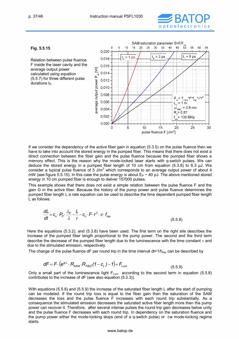
Fig. 5.5.15 Relation between pulse fluence F inside the laser cavity and the average output power calculated using equation (5.5.7) for three different pulse durations tP.
If we consider the dependency of the active fiber gain in equation (5.3.5) on the pulse fluence then we have to take into account the stored energy in the pumped fiber. This means that there does not exist a direct connection between the fiber gain and the pulse fluence because the pumped fiber shows a memory effect. This is the reason why the mode-locked laser starts with q-switch pulses. We can deduce the stored energy in a pumped fiber length of 10 cm from equation (5.3.8) to 6.3 µJ. We consider a typical pulse fluence of 5 J/m2 which corresponds to an average output power of about 4 mW (see figure 5.5.15). In this case the pulse energy is about EP ~ 40 pJ. The above mentioned stored energy in 10 cm pumped fiber is enough to deliver 157000 pulses. This example shows that there does not exist a simple relation between the pulse fluence F and the gain G in the active fiber. Because the history of the pump power and pulse fluence determines the pumped fiber length L a rate equation can be used to describe the time dependent pumped fiber length L as follows:
rep2
nP
Pn frFcLPcdtdL
(5.5.8)
Here the equations (5.3.2). and (5.3.8) have been used. The first term on the right site describes the increase of the pumped fiber length proportional to the pump power. The second and the third term describe the decrease of the pumped fiber length due to the luminescence with the time constant and due to the stimulated emission, respectively. The change of the pulse fluence dF per round trip in the time interval dt=1/fRep can be described by
LumLFBGSAMLg F1)c1(RReFdF
(5.5.9) Only a small part of the luminescence light FLum according to the second term in equation (5.5.8) contributes to the increase of dF (see also equation (5.3.3)). With equations (5.5.8) and (5.5.9) the increase of the saturated fiber length L after the start of pumping can be modeled. If the round trip loss is equal to the fiber gain then the saturation of the SAM decreases the loss and the pulse fluence F increases with each round trip substantially. As a consequence the stimulated emission decreases the saturated active fiber length more then the pump power can recover it. Therefore, after several intense pulses the round trip gain decreases below unity and the pulse fluence F decreases with each round trip. In dependency on the saturation fluence and the pump power either the mode-locking stops (end of a q-switch pulse) or cw mode-locking regime starts.

p. 38/46 Instruction manual PSFL1030
_
www.batop.de
This behavior is shown in figures 5.5.16 to 5.5.21, where the time dependency of the pulse fluence is calculated for different pump power values PP according to equations (5.5.8) and (5.5.9). Fig. 5.5.16 Q-switch mode-locking at 20 mW pump power. At time t~ 45 µ the round trip gain is ~ 1. Then the SAM is saturated and the pulse fluence increases during a few round trips to F ~ 80 J/m2. Then the pulse fluence decreases step by step because more inversion in the active fiber is removed by stimulated emission than pumped in the same time. At t =+ 185 µs the Q-switch pulse stops.
Fig. 5.5.17 Q-switch mode-locking at 22 mW pump power. The peak fluence is the same as with 20 mW pump power. After stop of the first Q-switch pulse the fiber gain increases due to continuous pumping until the next Q-switch pulse can start.
Fig. 5.5.17 Q-switch mode-locking at 22 mW pump power. The peak fluence is the same as with 20 mW pump power but the duration of the Q-switch pulse is somewhat longer because of the increased pump power.

p. 39/46 Instruction manual PSFL1030
_
www.batop.de
Fig. 5.5.18 Q-switch mode-locking at 22 mW pump power with an extended time scale showing the single mode-locked pulses during the start of the Q-switch pulse train. During the SAM saturation the maximum gain is about 1.15.
Fig. 5.5.19 Continuous wave mode-locking at 23 mW pump power. The start phase is the same as in case of a Q-switch train but because of the increased pump power the pulse train does not stop and ends up cw-ML with an average output power of 2.8 mW.
Fig. 5.5.20 Continuous wave mode-locking at 33 mW pump power. The start phase is similar as for lower pump power. The decrease of the pulse amplitude after its maximum is somewhat weaker resulting in an higher average output power.

p. 40/46 Instruction manual PSFL1030
_
www.batop.de
Fig. 5.5.21 Continuous wave mode-locking at 21 mW pump power with a pulse duration tP = 3 ps. The shorter pulse duration results in a lower maximum pulse fluence during the start phase and allows also cw-ML at a lower pump power. This shows the influence of the nonlinear transmittance of the narrow band FBG which avoids high pulse amplitude.
Conclusions
Q-switch mode-locking (Q-ML) starts, if the gain compensates the losses in the cavity according to the amplitude condition of an oscillator.
Because of decreasing loss in the SAM with increasing pulse fluence the pulse amplitude increases during a few round trips very fast. This is because the saturation fluence of the SAM is substantially lower then that of the active fiber. Therefore, a high pulse amplitude is possible for several cycles without a substantial decrease of the gain. Then the fiber gain decreases because the pump power is too low to compensate the loss of gain due to stimulated emission. With decreasing pulse fluence the absorption loss in the SAM increases and lasing stops.
The start of a new Q-switched pulse train is possible when the fiber gain is recovered after some pump time. The starting time depends on random fluctuations of the amplified spontaneous emission in the pumped fiber.
Continuous wave mode-locking (cw-ML) is possible if the pump power exceeds a certain value which ensures the recovery of the gain between two pulses. With increasing pump power the average cw-ML output power increases also.
The start phase of cw-ML is similar as the start of Q-ML with the same maximum pulse amplitude.
The maximum pulse amplitude during the start phase decreases with decreasing pulse duration. Shorter pulses have larger peak amplitudes at the same pulse fluence. This results in increased nonlinear spectral broadening and increasing FBG transmission loss.
In general any nonlinear effect showing an increasing loss with increasing pulse amplitude is helpful to avoid high maximum pulse amplitude and to ensure a low pump threshold for cw-ML. Besides the use of a narrow band FBG as amplitude limiting element also the two photon absorption (TPA) in the SAM (especially at shorter pulsedurations) and the increase of SAM absorption and saturation fluence with increasing SAM temperature are such limiting effects which allow cw-ML at a low pump power level.

p. 41/46 Instruction manual PSFL1030
_
www.batop.de
5.6 Picosecond laser, WDM coupler inside the cavity This laser configuration results in a longer cavity and an additional loss in the filter WDM coupler. 5.6.1 Experiment Needed parts from PSFL130 evaluation kit:
Optional
_
5 x Mating Sleeve
Additional equipment needed:
Optional:_
Optional: Autocorrelator
Schematic The photo diode (PD) can be replaced by an optical spectrum analyzer (OSA) to measure the spectral distribution of the emitted picosecond laser pulses
. This experiment differs only in the position of the WDM filter coupler from the setup in chapter 5.5. Because here the WDM filter is positioned inside the laser cavity the repetition frequency is lower due to the longer cavity length LC. The needed pump power is higher as a result of the additional loss in the filer WDM which must be compensated with a higher gain in the active fiber. A further consequence of the longer cavity length is larger normal dispersion. Measurement: Switch on the DL-975-100 and increase step by step the drive current of the 975 nm laser diode above the threshold current of ca. 20 mA. The Yb-doped fiber laser starts lasing at 1030 nm above the threshold pump power of ~ 15 mW. This can be monitored with the optical power meter (PM) and the photo diode (PD) with the oscilloscope. The FBG can be placed in the optical path with two different directions. Because of the chirp the lasing threshold and the slope efficiency depend on the FBG direction. This can be experimentally proved.
WDM C > 1 µm
< 1 µm
90
10
1x2 1 m
PD PM OSA
10
90 FBG
1x2
PD
PM SAM
R
P WDM
DL975
Yb C
PHS
DL975 Yb FBG SAM
PHS

p. 42/46 Instruction manual PSFL1030
_
www.batop.de
The repetition frequency can be reduced by insertion of the 1 m long passive fiber PM980-XP in the laser cavity between the SAM and the active fiber. The pump threshold for q-switching and cw ML and also the pump power region for stable mode-locking Pp,max - Pp,min can be measured for the different laser configurations. The spectral pulse width can be measured with an OSA in the same way as explained in the previous chapter 5.5. Measurement results Figure 5.6.2 Average laser output power Pav as a function of 980 nm pump power PP.
5.6.2 Discussion of the measured results Threshold pump power If we compare the onset of q-switching in figure 5.6.2 with the equivalent result in case of the filter WDM outside the cavity in figure 5.5.2, then the influence of the transmission loss in the filter WDM can be seen. To start the laser with WDM inside the cavity about 5 mW more optical pump power is needed to compensate the transmission loss of the WDM. Using the gain formula 5.3.5 with the power specific gain coefficient gP = 47.6/W and the additional pump power of 5 mW the needed extra gain in the active fiber to compensate the WDM loss is 1.27. This value corresponds to the measured WDM transmission of 0.8. Slope efficiency The WDM transmission loss in the cavity decreases also the slope efficiency of the laser power characteristic. Clearly, the laser pulses must go through the WDM in both cases, WDM inside and outside the laser cavity before they meet the optical power meter. But if the WDM is insight the laser cavity, the pulses must go through the WDM twice in a cavity round trip whereas if the WDM is outside the cavity the pulse go only once through the WDM. Conclusions
To get high laser efficiency the losses inside the laser cavity must be minimized. The optimum laser configuration is with WDM outside the cavity.
p. 43/46 Instruction manual PSFL1030
_
www.batop.de
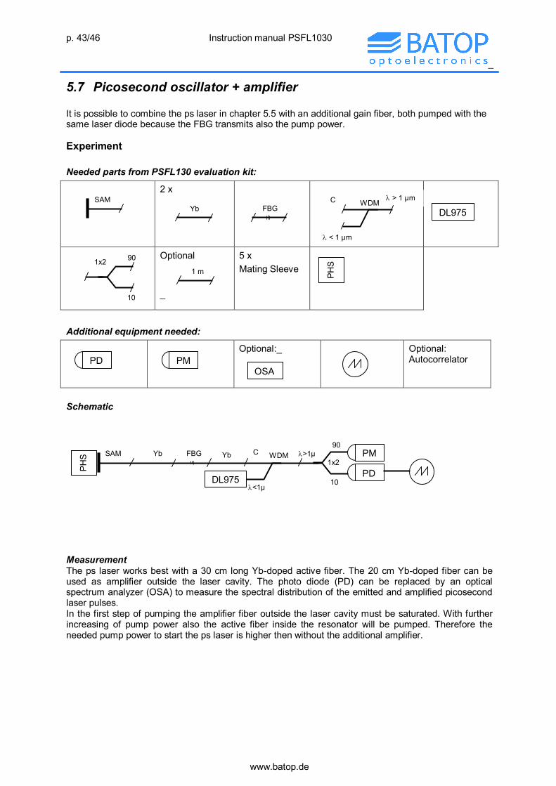
5.7 Picosecond oscillator + amplifier It is possible to combine the ps laser in chapter 5.5 with an additional gain fiber, both pumped with the same laser diode because the FBG transmits also the pump power. Experiment Needed parts from PSFL130 evaluation kit:
2 x
Optional
_
5 x Mating Sleeve
Additional equipment needed:
Optional:_
Optional: Autocorrelator
Schematic
Measurement The ps laser works best with a 30 cm long Yb-doped active fiber. The 20 cm Yb-doped fiber can be used as amplifier outside the laser cavity. The photo diode (PD) can be replaced by an optical spectrum analyzer (OSA) to measure the spectral distribution of the emitted and amplified picosecond laser pulses. In the first step of pumping the amplifier fiber outside the laser cavity must be saturated. With further increasing of pump power also the active fiber inside the resonator will be pumped. Therefore the needed pump power to start the ps laser is higher then without the additional amplifier.
WDM C > 1 µm
< 1 µm
90
10
1x2 1 m
PD PM OSA
>1µ Yb 90
10
SAM Yb
<1µ
C WDM FBG
DL975
1x2 PD
PM
PHS
DL975 FBG SAM
PHS
Yb

p. 44/46 Instruction manual PSFL1030
_
www.batop.de
Figure 5.7.2 Average output power Pav of the oscillator + amplifier combination as a function of 980 nm pump power PP.
Figure 5.7.3 Spectral laser + amplifier emission, measured with an OSA at two pump power levels PP.. The laser works at a low power level only somewhat above the threshold for cw ML. The spectrum is therefore small.
Discussion of the measured results With the oscillator-amplifier combination a reasonable efficiency can be realized for the conversion of pump light into picosecond pulses. An important advantage of this combination over the pure oscillator setup is the lower pulse fuence on the SAM, which ensures a lower temperature of the absorber layer and consequently a lower long time degradation of the saturable absorber mirror. This is important for applications of the ps laser source. With more pump power also a higher output power will be possible. The spectral width of the output pulses is small because of the low power level in the oscillator. The shape of the spectral power distribution in case of higher pump power is nearly flat top. This can be explained with gain saturation. The pumped active fiber stores an amount of energy. By stimulated emission some energy is added to a pulse traversing the pumped fiber. Because the stored energy is limited, the amplification is higher for a lower signal. This results in spectral equalization of the output power.

p. 45/46 Instruction manual PSFL1030
_
www.batop.de
5.8 FBG transmittance The spectral transmittance of the fiber Bragg grating FBG-1030-0.8-87-FC/APC-PM980-XP can be measured using the broadband luminescence of the Yb-doped fiber light source. Needed parts from PSFL130 evaluation kit:
_
2 x
Mating Sleeve
Additional equipment needed:
_
Schematic
The FBG can be replaced by the passive fiber FBG-1030-0.8-87-FC/APC-PM980-XP to measure the “100 %” calibration curve Measurement: Switch on the DL-975-100 and increase step by step the drive current of the 975 nm laser diode above the threshold current of ca. 20 mA. The Yb-doped fiber laser starts broadband luminescence, which can be measured using the optical spectrum analyzer (OSA). Please be aware, that you work with a low luminescence level to avoid a power damage of the OSA detector. To calculate the spectral transmittance of the FBG two measurements are needed with the same pump power:
Spectral transmission through the FBG. Spectral transmission through a passive fiber.
The spectral transmittance T of the FBG results from the transmitted spectral power through the FBG divided by the measured spectral power trough the passive fiber PM980-XP-100-FC/APC . The absorption in the FBG is negligible. Therefore the reflectance R of the FBG is simply R = 1 –T.
C
R
P WDM 1 m
OSA
FBG
R
P WDM
DL975
Yb C OSA
DL975
Yb FBG

p. 46/46 Instruction manual PSFL1030
_
www.batop.de
Measurement results Figure 5.8.2 Spectral transmission T of the FBG-1030-0.8-87-FC/APC-PM980-XP. The minimum transmission at ~ 1030 nm wavelength corresponds to the maximum reflection at this wavelength. An extended view of the transmission is shown in figure 4.4.1.
Discussion of the result The transmittance T of the FBG is almost 1 besides the small spectral region around the reflection wavelength of ~ 1030 nm. To measure the exact spectral bandwidth and the minimum transmission the wavelength step of the OSA scan must be chosen appropriate small.
6. Ordering information All parts of the evaluation kit PSFL1030 (items 1 – 14) can be ordered as replacement pieces. Please use the Part No. for ordering. Besides the parts of the evaluation kit the following additional equipment can be ordered from BATOP if needed:
Laser safety goggles
Fast photo diode to trace the time dependent laser output signal from ALPHALS ?
Digital optical power and energy meter from Thorlabs with sensor head S120C and FC adapter S120-FC or: Fiber Optic JW3216C handheld Optical Power Meter Tester -50 ~ +26dBm USB for < 300 €
Fiber inspection scope FS200 from Thorlabs Optical magnification: 200 x field of view: 600 µm diameter LED illumination
7. Support Producer: BATOP GmbH Address: Stockholmer Str. 14, 07747 Jena, Germany Tel: +49 (0)3641 6340090 Email: [email protected] Website: http://www.batop.de