Evaluating the effects of seismic loading on concrete ...
61
University of Mississippi University of Mississippi eGrove eGrove Honors Theses Honors College (Sally McDonnell Barksdale Honors College) Spring 5-1-2021 Evaluating the effects of seismic loading on concrete reinforced Evaluating the effects of seismic loading on concrete reinforced versus precast concrete slab floor systems versus precast concrete slab floor systems Mahima Maharjan Follow this and additional works at: https://egrove.olemiss.edu/hon_thesis Part of the Structural Engineering Commons Recommended Citation Recommended Citation Maharjan, Mahima, "Evaluating the effects of seismic loading on concrete reinforced versus precast concrete slab floor systems" (2021). Honors Theses. 1905. https://egrove.olemiss.edu/hon_thesis/1905 This Undergraduate Thesis is brought to you for free and open access by the Honors College (Sally McDonnell Barksdale Honors College) at eGrove. It has been accepted for inclusion in Honors Theses by an authorized administrator of eGrove. For more information, please contact [email protected].
Transcript of Evaluating the effects of seismic loading on concrete ...

University of Mississippi University of Mississippi
eGrove eGrove
Honors Theses Honors College (Sally McDonnell Barksdale Honors College)
Spring 5-1-2021
Evaluating the effects of seismic loading on concrete reinforced Evaluating the effects of seismic loading on concrete reinforced
versus precast concrete slab floor systems versus precast concrete slab floor systems
Mahima Maharjan
Follow this and additional works at: https://egrove.olemiss.edu/hon_thesis
Part of the Structural Engineering Commons
Recommended Citation Recommended Citation Maharjan, Mahima, "Evaluating the effects of seismic loading on concrete reinforced versus precast concrete slab floor systems" (2021). Honors Theses. 1905. https://egrove.olemiss.edu/hon_thesis/1905
This Undergraduate Thesis is brought to you for free and open access by the Honors College (Sally McDonnell Barksdale Honors College) at eGrove. It has been accepted for inclusion in Honors Theses by an authorized administrator of eGrove. For more information, please contact [email protected].

EVALUATING THE EFFECTS OF SEISMIC LOADING ON CONCRETE REINFORCED
VERSUS PRECAST CONCRETE SLAB FLOOR SYSTEMS
By
Mahima Maharjan
A thesis submitted to the faculty of The University of Mississippi in partial fulfillment of the
requirements of the Sally McDonnell Barksdale Honors College.
Oxford, MS
April 2021
Approved By
______________________________
Advisor: Dr. Ahmed Al-Ostaz
______________________________
Advisor: Dr. Hunain Alkhateb
______________________________
Reader: Dr. Ken Thomas

ii
©2021
Mahima Maharjan
ALL RIGHTS RESERVED

iii
DEDICATION
This thesis is dedicated to everyone who has helped me throughout my undergraduate
degree, especially my grandparents, Mr. Ganesh Bahadur Maharjan, Mrs. Heramaya Devi
Maharjan, and Mrs. Anar Keshari Singh.

iv
ACKNOWLEDGEMENT
It is a genuine pleasure to express my deep gratitude to Dr. Hunain Alkhateb, Dr.
Christopher Mullen, and Dr. Ahmed Al-Ostaz for their time and energy in making this work
successful. I must thank Dr. Mullen for his help throughout the semester to motivate me in
researching more about earthquake design and providing materials related to my study. Although
my research with Dr. Hunain and Dr. Al Ostaz was not completed due to the ongoing pandemic,
my special thanks to them for inspiring me to become a part of Honor’s College, supporting my
work, and helping me throughout the entire process.
I feel so grateful to be a part of Sally McDonnell Barksdale Honors College, and my special
thanks to Dr. John Samonds and Dr. Ken Thomas for guiding me regarding the honor thesis
requirements. Next, I would like to thank all my professors at Ole Miss especially Dr. Yacoub
Najjar, Dr. Christine Surbeck, Dr. Hakan Yasarer, Dr. Elizabeth Ervin, Dr. Waheed Uddin, Dr.
Matteo D’Alessio, and Mrs. Grace Rushing for assisting me throughout my undergraduate degree.
They all have given their best efforts in uplifting my knowledge and pushing me to reach my
maximum potential.
I would also like to thank my senior design teaching assistant Oubayda Sras and my
teammates for guiding me and making this work successful. I am grateful to Ole Miss School of
Engineering for this opportunity. Moreover, I would like to thank my friends for motivating me
and being a source of joy.
Lastly, I would like to thank my family, especially my mom and dad for their infinite
support and love. I would haven’t been able to complete this work without their encouragement
and unending motivation.

v
ABSTRACT
This thesis is part of the senior design capstone project of Ole Miss Department of Civil
Engineering. The seismic loadings for the commercial buildings project located in Oxford,
Mississippi are evaluated to fulfill the honor thesis requirement. This thesis follows the codes from
American Concrete Institute (ACI), International Building Code (IBC), and ASCE-7/SEI
(Minimum Design Loads and Associated Criteria for Buildings and Other Structures/Structural
Engineering Institute) to design the gravitational loadings and seismic loadings.
Furthermore, a reinforced concrete slab flooring system is replaced with a precast slab
flooring system to analyze the most seismic performance effective floor system for the building.
Both structural systems are analyzed using SAP 2000. Also, a cost analysis is executed to estimate
the price difference and to select suitable flooring systems.

vi
Contents
DEDICATION ............................................................................................................................................ III
ACKNOWLEDGEMENT ......................................................................................................................... IV
ABSTRACT .................................................................................................................................................. V
LIST OF TABLES .................................................................................................................................... VII
LIST OF FIGURES .................................................................................................................................. VII
LIST OF ABBREVIATIONS .................................................................................................................... IX
CHAPTER 1: INTRODUCTION ................................................................................................................ 1
1.1 PROJECT OVERVIEW ............................................................................................................................... 1 1.2 PROJECT OUTLINE .................................................................................................................................. 2 1.3 STRUCTURAL LOAD ............................................................................................................................... 6
CHAPTER 2: REINFORCED CONCRETE SLAB SYSTEM ................................................................. 8
2.1 GRAVITATIONAL LOAD CALCULATION .................................................................................................. 8 2.1.1 DEAD LOAD ........................................................................................................................................ 8 2.1.2 ESTIMATING SUPERIMPOSED DEAD LOAD .......................................................................................... 9 2.1.3 ESTIMATING LIVE LOAD ................................................................................................................... 10 2.2 ESTIMATING ENVIRONMENTAL LOAD .................................................................................................. 10 2.3 COMBINED LOAD EFFECT .................................................................................................................... 11
CHAPTER 3: SEISMIC LOAD ESTIMATION FOR RC SLAB .......................................................... 14
3.1 ESTIMATION FOR THE SEISMIC LOADING. ............................................................................................. 15
CHAPTER 4: PRECAST CONCRETE SLAB SYSTEM ....................................................................... 22
4.1 ESTIMATING THE LOAD ........................................................................................................................ 23 Estimating Dead Load ......................................................................................................................... 23
5. RESULTS AND DISCUSSION ......................................................................................................... 26
5.1 BEAM ANALYSIS .................................................................................................................................. 27 5.2 COST ANALYSIS ................................................................................................................................... 29
6. SUMMARY AND CONCLUSIONS ................................................................................................. 31
7. RECOMMENDATION ...................................................................................................................... 32
REFERENCES ............................................................................................................................................ 33
APPENDICES ............................................................................................................................................. 36
APPENDIX A- SAMPLE CALCULATIONS .................................................................................................. 36 APPENDIX B- SAP 2000 RESULTS .......................................................................................................... 44 APPENDIX C - DATA ............................................................................................................................. 47

vii
LIST OF TABLES
Table 2. 1: Superimposed Load Calculations ..................................................................... 9
Table 2. 2: Live Load based on the occupancy of the building ........................................ 10
Table 2. 3: Environmental Load for Oxford, MS ............................................................. 10
Table 3. 1: Determination of risk category based on 2015 IBC-1604. ............................. 17
Table 3. 2: Distribution of shear over the height of the structure ..................................... 20
Table 3. 3: Critical Loading Combinations with without seismic and with seismic case 21
Table 4. 1: Self-weight calculation for prestressed concrete. ........................................... 24
Table 4. 2: Distribution of shear over the height of structure for precast concrete .......... 24
Table 4. 3: Comparison of maximum shear and bending moment in various cases. ........ 26
Table 4. 4: Reduction in the load ...................................................................................... 27
Table 4. 5: Analysis of Beam B3 ...................................................................................... 27
Table 4. 6: Cost Analysis for hollow core slab and precast slab ...................................... 29
LIST OF FIGURES
Figure 1. 1: Project Location on Sisk Avenue. ................................................................... 2
Figure 1. 2: Overall Plan view of the project ...................................................................... 3
Figure 1. 3: Floor Outline for Building A ........................................................................... 4
Figure 1. 4: Floor Outline for Building B ........................................................................... 4
Figure 1. 5: Structural floor Plan for Building A ................................................................ 6
Figure 2. 1: Minimum Thickness of one-way slabs. ........................................................... 8
Figure 2. 2: Selected section for the moment frame of Building A .................................. 11
Figure 2. 3: Total dead load applied to the moment frame. .............................................. 12
Figure 2. 4: Total live load applied to the moment frame. ............................................... 13
Figure 2. 5: Deflection under the influence of live and dead load (LC2) ......................... 13
Figure 3. 1: Earthquake Zone for the Oxford, Mississippi ............................................... 14
Figure 3. 2: Moment frame for B3 and B8 ....................................................................... 15
Figure 3. 3: ASCE Hazard Tool Output for Oxford, MS.................................................. 16
Figure 3. 4: Design Coefficients and Factors for Seismic Force-Resisting Systems........ 18

viii
Figure 3. 5: Seismic load applied to the moment frame. .................................................. 21
Figure 3. 6: Deflection under the influence of dead and live load (LC2) ......................... 21
Figure 3. 7: Deflection under the influence of seismic, live, and dead load (LC5) .......... 21
Figure 4. 1: Precast Concrete Hollow Slab ....................................................................... 23
Figure 4. 2: Dead Load for the hollow core slab .............................................................. 25
Figure 4. 3: Live Load for the hollow core slab ............................................................... 25
Figure 4. 4: Seismic Load for the hollow core slab .......................................................... 25
Figure A. 1: Calculation for the weight of the structure for RC slab floor system ........... 36
Figure A. 2: LRFD combinations for Beam B3 for RC system without seismic loading 37
Figure A. 3: LRFD combinations for Beam B8 for RC system without seismic loading 37
Figure A. 4: Seismic Load Calculation for RC slab floor system .................................... 37
Figure A. 5: LRFD combinations for Beam B3 for RC system with seismic loading ..... 38
Figure A. 6: LRFD combinations for Beam B8 for RC system with seismic loading ..... 38
Figure A. 7: Calculation for the weight of the structure for PC slab floor system ........... 39
Figure A. 8: LRFD load combinations for Beam B3 for PC structural system ................ 40
Figure A. 9: LRFD load combinations for Beam B8 for PC structural system ................ 40
Figure A. 10: Seismic Load Calculation for PC slab floor system ................................... 41
Figure A. 11: Design of Beam B3 only on gravitational load for RC slab. ...................... 41
Figure A. 12: Design of Beam B3 in presence of seismic load for RC slab. .................... 42
Figure A. 13: Design of Beam B3 considering seismic load for PC slab. ........................ 42
Figure A. 14: Total weight of building for RC slab floor systems ................................... 43
Figure A. 15: Total weight of building for RC slab floor systems ................................... 43
Figure B. 1: Shear diagram for RC without seismic loading ............................................ 44
Figure B. 2: Moment diagram for RC without seismic loading ....................................... 44
Figure B. 3: Shear diagram for RC with seismic loading ................................................. 45
Figure B. 4: Moment diagram for RC with seismic loading............................................. 45
Figure B. 5: Shear diagram for PC with seismic loading ................................................. 46
Figure B. 6: Moment diagram for PC with seismic loading ............................................. 46
Figure C. 1: ASCE-7 Table 11.4.1 and 11.4.2 .................................................................. 47
Figure C. 2: Table to determine the concrete steel ratio 𝜌 ................................................ 48
Figure C. 3: Table to determine bar size for the beam B3 ................................................ 49

ix
LIST OF ABBREVIATIONS
𝜀𝑡 net tensile strain in an extreme layer of longitudinal tension reinforcement
Ф safety factor for beam bending design, a value equal to 0.9 for a 10% reduction
ρ steel fraction percentage of the concrete area
ACI American Concrete Institute
AISC American Institute of Steel Construction
𝐴𝑠 the required area of steel bar in square inches
b width of the beam
𝐶𝑠 seismic response coefficient
𝐶𝑣𝑥 vertical distribution factor
d depth of the beam
DL Dead Load
𝐹𝑎 short period site coefficient (at 0.2 second period) [ASCE-7 Table 11.4.1]
𝑓𝑐′ specified compressive strength of the concrete
𝐹𝑣 long-period site coefficient at 1 second period [ASCE-7 Table 11.4.2]
𝐹𝑥 lateral seismic load for each floor in kips
𝑓𝑥 lateral seismic load for each floor in kips/feet
𝑓𝑦 yield strength or stress

x
h height of the beam
HC Hollow core
ℎ𝑠 height of the slab
ℎ𝑥 height of the structure from the base
HVAC Heating, Ventilation, and Air conditioning
IBC International Building Code
𝐼𝑒 Seismic Importance factor
LC Load Cases
LL Live Load
LRFD Load and Resistance Factor Design
𝑀𝐶𝐸𝑅 Risk targeted maximum considered earthquake
𝑀𝑢 Ultimate moment
PC Precast Concrete
PCI Prestressed/Precast Concrete Institute
psf pounds per square foot
𝑆1 Spectral response accelerations at 1 second period
𝑆𝑠 Spectral response accelerations at short periods
𝑆𝐷1 5 percent damped design spectral response accelerations at 1 second period

xi
𝑆𝐷𝑆 5 percent damped design spectral response accelerations at short periods
RC Reinforced Concrete
USGS United States Geological Survey
V seismic base shear
𝑤𝑥 weight of each floor
𝑤𝑠 self-weight of the one-way solid slab in pounds per square foot

1
Chapter 1: Introduction
A part of the senior design capstone tasks for the civil engineering senior students was
designing and analyzing a commercial building project. The project is located at Sisk Avenue,
Oxford, Mississippi with the latitude and longitude of 34°22'21.7"N and 89°29'48.1"W. The civil
engineering capstone project consisted of six main design and analysis tasks i.e. site planning,
analyzing subsurface exploration, analyzing and designing the structural system, foundation, and
stormwater systems. The emphasis is on the structural analysis and design part of the capstone
project.
The main focus of the structural loading part was to analyze the loadings for the building
so that the structural members can be designed based on that. For the honor thesis, the objective
was to investigate the lateral loading effects especially from the earthquake loadings generated due
to the location of the building. Moreover, two slab systems were studied to evaluate the seismic
loadings on the structural system response.
1.1 Project overview
The design project consisted of two buildings located in consecutive plots at Oxford
Commons, Mississippi. Each plot has an area of 1.17 acres and will have a two-story building. The
Sisk Avenue is in the north, Commonwealth Blvd on East, Enterprise Drive on West, and the
Hopkins Drive on South of the project location shown in Figure 1.1.

2
Figure 1. 1: Project Location on Sisk Avenue [11]
1.2 Project Outline
The students were tasked to select the floor plans and functionality of the buildings. Based
on the Oxford Ordinance and city regulations, the layout of the building is selected as presented in
Figure 1.2 [17]. Each building has dimensions of 120’×98’.

3
Figure 1. 2: Overall Plan view of the project
As shown in Figure 1.3, Building A's first floor is a Trader Joe’s store and the second floor
is for dental care and offices. On the other hand, Building B consists of offices, a smoothie king,
gym, vitamin shop, and pet store.

4
Figure 1. 3: Floor Outline for Building A [5]
Figure 1. 4: Floor Outline for Building B [5]

5

6
Figure 1. 5: Structural floor Plan for Building A [5]
1.3 Structural Load
Structural Load is the total amount of forces or the loads carried by the building including
its self-weight. These loads can cause deformation, stress, and displacements of the building or the
structural members of the building [21]. It is essential to determine the structural load applied to a
building to ensure structural stability and this helps to predict the various modes of failure in case
of different scenarios. The structure must be designed in a way to withstand the various loads
during its service life.
There are various types of loads generated in the building based on the selected
construction materials, structural system, and location of the building [21]. Some of the major
applied loads are given below:

7
1. Dead load: A dead load of a structure generated from beams, slabs, and columns. In other
words, the dead load is the total non-dynamic structural load of the system. It is a load that
depends on the materials used for the construction like concrete, timber, or steel.
2. Superimposed dead load: Superimposed dead loads depends on periodic occupancy of the
structure. These loads are semi-dynamic and can rotate around different areas of the
structure. Some of the sources of the dead load include floor finish, window/frames,
electrical wiring, stairs, elevators, HVAC ductwork, and plumbing.
3. Live loads: Live loads result from dynamic forces due to occupancy and functionality of
the structure. They represent the transient forces that can be moved through the building or
act on any particular structural element. Some of the sources of live loads are the weight
of people, furniture, appliances, and automobiles including other moveable equipment.
4. Environmental loads: The external dynamic loads resulting from natural activities like
snow, wind, rain, soil movement, or earthquake (seismic) activity. It mainly depends on
the geographical and topographic conditions.

8
Chapter 2: Reinforced Concrete Slab System
Reinforced Concrete is a composite material made up of steel bars and concrete. Concrete
is the mixture of cement, water, and aggregates (sand and gravel) that hardens over time. It is the
second most-consumed material on the earth. Besides the steel rebar in the concrete is mostly made
of recycled steel which makes it a sustainable product.
In reinforced concrete, steel bars provide tensile strength i.e. strength to resist pull force,
and concrete provides compressive strength i.e. strength to resist compression. It is a durable,
aesthetically pleasing, and fire-resistant material used in construction.
2.1 Gravitational Load Calculation
2.1.1 Dead Load
Estimating the slab self-weight
According to American Concrete Institute (ACI) code 7.3.1.1 and 9.3.1.1, the minimum
thickness in one way slab with the deflection criteria is shown in Figure 2.1.
Figure 2. 1: Minimum Thickness of one-way slabs. [10]

9
For the solid one-way slab with one end continuous, the minimum thickness of the slab
(ℎ𝑠) = 𝑆𝑝𝑎𝑛 𝐿𝑒𝑛𝑔𝑡ℎ (𝐿)
24=
24𝑓𝑡
24∗
12 𝑖𝑛
1𝑓𝑡 = 12 𝑖𝑛𝑐ℎ𝑒𝑠 = 1 𝑓𝑒𝑒𝑡
𝑆𝑒𝑙𝑓 𝑤𝑒𝑖𝑔ℎ𝑡 𝑜𝑓 𝑠𝑙𝑎𝑏 (𝑤𝑠) = 𝐷𝑒𝑛𝑠𝑖𝑡𝑦 𝑜𝑓 𝑐𝑜𝑛𝑐𝑟𝑒𝑡𝑒 𝑥 ℎ𝑒𝑖𝑔ℎ𝑡 𝑜𝑓 𝑠𝑙𝑎𝑏
= 150𝑙𝑏
𝑓𝑡3× 1 𝑓𝑡 = 150𝑝𝑠𝑓
2.1.2 Estimating Superimposed Dead Load
The superimposed load of the building is determined through the American Institute of
Steel Construction (AISC). As shown in Table 2.1, the superimposed load for the first floor is 58.5
psf and the roof is 7 psf.
Table 2. 1: Superimposed Load Calculations
For the
first floor
Structural component Load (psf)
Floor Finish(Hardwood, 7/8 in) 4
Window (glass, frame and ) 8
Partition (Drywall, 5/8 in) 2.5
Mechanical Duct 4
Piping (8in diameter) 40
58.5
For roof
Roof finish (wood, 3/4 in) 3
Mechanical Duct 4
7

10
2.1.3 Estimating Live Load
The live load of the building is determined through International Building Code (IBC-
2016) and Table 2.2 summarizes the live load for the structure based on occupancy.
Table 2. 2: Live Load based on the occupancy of the building [12]
Floor Functionality/Occupancy Live Load (psf)
First floor Trader Joe’s shopping area 125
Mechanical Room and storage 100
Second floor Lobby, corridor offices 100
Dental care 60
Roof General roof live load 20
2.2 Estimating Environmental Load
The environmental load is mainly considered based on the weather and location of the city.
The environmental load considered for Oxford, MS is summarized in Table 2.3.
Table 2. 3: Environmental Load for Oxford, MS
Environmental Load Load (psf)
Rain Load 20
Snow Load 10
To analyze the difference between various loading conditions on the structural member, a
moment frame system from Building A is selected as presented in Figure 2.2. A moment frame is
a special type frame that uses rigid connections between its members [2]. This arrangement resists

11
lateral and overturning forces induced by bending moment and shear forces [7]. Because of the
building symmetry, the analysis of a moment frame can represent the whole system when applied
lateral earthquake load.
Figure 2. 2: Selected section for the moment frame of Building A
2.3 Combined Load Effect
The load factors and combinations used in the reinforced concrete are presented in ACI
318 5.3. This is further verified in ASCE/SEI-7 and IBC. The selected method is known as Load
and Resistance Factor Design (LRFD). Following the codes, the various load cases are evaluated
and the most critical combination is selected.
The following equations are analyzed to determine the most critical factored combined load
applied to the building [13].
LC1: U = 1.4D (ACI Equation 5.3.1a)
LC2: U = 1.2D + 1.6L + 0.5(Lr or S or R) (ACI Equation 5.3.1b)
LC3: U = 1.2D + 1.6(Lr or S or R) + (L or 0.5W) (ACI Equation 5.3.1c)

12
LC4: U = 1.2D + 1.0W + L + 0.5(Lr or S or R) (ACI Equation 5.3.1d)
LC5: U = 1.2D + 1.0E + L + 0.2S (ACI Equation 5.3.1e)
LC6: U = 0.9D + 1.0W (ACI Equation 5.3.1f)
LC7: U = 0.9D + 1.0E (ACI Equation 5.3.1g)
Where U = ultimate load of the structure needs to resist
D = Dead Load L = Live Load
Lr = Roof Live Load S = Snow Load
R = Rain Load W = Wind Load
E = Seismic or Earthquake Load effects
All these load cases are investigated to determine the maximum loading cases. The load
case 2 was the maximum for the gravity load cases. However, when the seismic load was
considered the LC 5 was maximum for the roof and LC 2 was maximum for the first floor as shown
in Appendix A Figures A.2 and A.3.
SAP 2000 analysis was performed to determine the bending moment on the moment-
resisting frame based on LC 2 [9]. All the calculations are performed in Excel shown in the figures
in Appendix A.
Figure 2. 3: Total dead load applied to the moment frame.

13
Figure 2. 4: Total live load applied to the moment frame.
Figure 2. 5: Deflection under the influence of live and dead load (LC2)

14
Chapter 3: Seismic Load Estimation for RC slab
The seismic loading is the response of the structure to earthquake oscillation. It depends
on various parameters like geotechnical parameters, the seismic location of the site, and the
building’s natural frequency. The seismic force has both horizontal and vertical components [24].
However, the horizontal forces mainly cause the failure so only horizontal forces are mainly
considered for the design.
Earthquake generally occurs along the boundary of a plane because of moving crustal plates
which are thousands of feet below the earth's surface. The nearest boundary plane is approximately
1700 kilometers south of Mississippi near the coast of Honduras, where the North American and
Caribbean plates join [20]. Oxford lies within the vicinity of the New Madrid Seismic Zone that
can result in moderate seismic activity as shown in Figure 3.1 below.
Figure 3. 1: Earthquake Zone for the Oxford, Mississippi [22]

15
Similarly, the same moment frame of Building A is analyzed for the seismic loading. As
the building is symmetrical, the analysis of a moment frame can represent the whole system when
earthquake load is applied.
Figure 3. 2: Moment frame for B3 and B8
3.1 Estimation for the seismic loading.
The seismic loading is determined using a seismic code master designed under the 2015
International Building Code (IBC) and ASCE/SEI 7-10 [8]. The multistep calculation processes
followed to determine the earthquake loading is shown below.
Step 1: Determining spectral response accelerations for risk-targeted maximum considered
earthquake (MCER)
The values for the spectral response accelerations at short periods (𝑆𝑠) and at 1-second
period (𝑆1) is determined following the United States Geological Survey (USGS). The
latitude/longitude for the location is provided on the ASCE-7 hazard tool and the output is
delivered as shown in Figure 3.3.

16
Figure 3. 3: ASCE Hazard Tool Output for Oxford, MS [4]
From Figure 3.3, 𝑆𝑠=0.416, S1=0.179
Step 2: Determine if the structure is exempt from the seismic requirements.
The city of Oxford, Mississippi lies in the moderate seismic zone so it is not exempted
from the seismic requirements.
Step 3: Structural Design Category (SDC)
The soil is classified as Class C soil in accordance with ASCE 7-10 and 2015 IBC for
Oxford, MS.
To determine the design spectral response acceleration, short period and long period
coefficient (Fa and Fv) are required. Following Table 11.4.1 and 11.4.2 from ASCE-7 and for soil
type C as shown in Figure C.1
𝐹𝑎=1.3 𝐹𝑣 =1.5

17
𝑆𝐷𝑆 =2
3𝐹𝑎𝑆𝑠 =
2
3(1.3)(0.416) = 0.361
𝑆𝐷1 =2
3𝐹𝑣𝑆1 =
2
3(1.5)(0.179) = 0.179
Determining the risk category:
The building is a public space with more than 300 people so Risk Category III is selected.
Table 3. 1: Determination of risk category based on 2015 IBC-1604.
Risk Category Nature of Occupancy
I Risk Category I is assigned to agricultural facilities, temporary facilities, and
minor storage facilities that represent a low hazard to human life in the event
of failure.
II Risk Category II is assigned to most structures; it is assigned to structures
not otherwise classified as Risk Category I, III, or IV.
III Risk Category III is for structures with large numbers of persons such as:
• Schools with more than 250 students.
• Assembly uses with more than 300 people, and
• Structures with total occupancy greater than 5000 people.
Risk Category III is also assigned to:]
• Nonessential utility facilities and
• Jails and detention facilities.

18
IV Risk Category IV includes hospitals and acute care facilities; fire, police, and
emergency response stations; aviation control towers; and utilizes required
for essential facilities.
Step 4: Determine responsive modification coefficient (R)
R is the rating for and ability of a structural system to resist earthquake ground motion
without collapse. The R is determined from ASCE 7 Table 12.2-1 for the moment-resisting frame
system. The equivalent lateral force method is selected for the analysis procedure of seismic
loadings.
Figure 3. 4: Design Coefficients and Factors for Seismic Force-Resisting Systems [3]

19
So, R for ordinary reinforced concrete moment frames =3
Step 5: Determine seismic importance factor (𝐼𝑒):
It is the seismic performance capabilities of structures in various risk categories. It modifies
the design base shear depending on the occupancy during the earthquake event. For risk category
III, 𝐼𝑒 = 1.25 which increases the design shear base by 25%.
Step 6: Determine seismic base shear (V): The base shear is calculated using the following
equations,
𝑉 = 𝐶𝑠𝑊
Where 𝐶𝑠= seismic response coefficient =𝑆𝐷𝑆
𝑅/𝐼𝑒
W=weight of the building = 2185.4 kips [From excel calculations]
𝐶𝑠 =𝑆𝐷𝑆
𝑅/𝐼𝑒=
0.36
3/1.25= 0.15
𝑉 = 𝐶𝑠𝑊 = 0.15 × 1592 = 239𝑘𝑖𝑝𝑠
Step 7: Distribute V over the height of the structure.
ASCE7-10 section 12.8.3 corresponds to design base shear distributed over the height of
the structure. 𝐹𝑥 = 𝐶𝑣𝑥𝑉
𝐶𝑣𝑥 =𝑤𝑥ℎ𝑥
𝑘
∑ 𝑤𝑖ℎ𝑖𝑘𝑛
𝑖=1

20
For the first floor
𝐶𝑣𝑥 =𝑤𝑥ℎ𝑥
𝑘
∑ 𝑤𝑖ℎ𝑖𝑘𝑛
𝑖=1
=971 ∗ 12
26564.4= 0.44
𝐹𝑥 = 0.44 ∗ 239 =104.92𝑘
120𝑓𝑡= 0.87𝑘/𝑓𝑡
Table 3. 2: Distribution of shear over the height of the structure
Floor hx (ft) wx (k) wxhx (kft) Cvx Fx (k) fx (k/ft)
First 12 971.0 11652 0.44 104.92 0.87
Roof 24 621.4 14913 0.56 134.28 1.12
Σwihi 26564.4
Step 8: Determine Redundancy Factor, 𝜌
According to ASCE 7-10 Section 12.3.4, for Seismic Design Category A, B, or C
structures, the redundancy factor is taken as 1. This simply means that the redundancy factor does
not apply.
Step 10: Load combinations
The earthquake effects are combined with the effects of gravity loads according to 2015
IBC Section 1605. The calculation is shown in Figure
LC1: U = (1.2 + 0.2SDS)D + f1L + f2S + ρQE
LC2: U = (0.9 − 0.2SDS)D + ρQE

21
Table 3. 3: Critical Loading Combinations with without seismic and with seismic case [1]
Load Combination Beam B3 (k/ft) Beam B8 (k/ft)
U = 1.2D + 1.6L + 0.5(Lr or S or R) 10.67 6.07
𝐔 = (𝟏. 𝟐 + 𝟎. 𝟐𝐒𝐃𝐒)𝐃 + 𝐟𝟏𝐋 + 𝐟𝟐𝐒 + 𝛒𝐐𝐄 10.51 7.44
Figure 3. 5: Seismic load applied to the moment frame.
Figure 3. 6: Deflection under the influence of dead and live load (LC2)
Figure 3. 7: Deflection under the influence of seismic, live, and dead load (LC5)

22
Chapter 4: Precast Concrete Slab System
Precast concrete is fabricated separately in the manufacturing plant and then installed on
the site. Precast members can be either reinforced or prestressed concrete. Prestressed concrete is
the formwork of concrete in which high-stress compressive force is induced due to steel tendons
prior to exposure to service loads. The prestressing generates a compressive force that helps to
counteract the tensile force after exposure to service loads. The precast member is usually used for
architectural elements i.e. to carry the structural load or non-structural portion of the building. It
is commonly used for floors, columns, walls, or roof components. Since it can be pre-casted away
from the site it helps in potential savings in time and economy.
In this section, the one-way solid slab is replaced with hollow-core precast concrete slab.
The hollow-core precast concrete slabs are analyzed and the loading is determined. The hollow-
core precast concrete slabs are lighter than the solid reinforced concrete slab. The main purpose
for replacing the slabs was to analyze the change in loadings and to evaluate the results when
lighter slab systems are used.
In terms of loading, the superimposed dead load, live load, rain load, and snow load remain
constant. However, the self-weight of the slab fluctuates which might cause a difference in overall
dead load and seismic loadings for the precast concrete slabs.

23
4.1 Estimating the load
As the live load, superimposed dead load, rain load and snow load remain the same, the
precast concrete slab is analyzed for dead load and seismic loadings only.
Estimating Dead Load
The hollow core slab was selected using the PCI handbook [16]. The hollow core slab
4HC6+2 of 87-S is selected for the slab as shown in Figure 4.1. The slab with 2-inch toppings is
selected as it provides a finished floor process and insulation.
Figure 4. 1: Precast Concrete Hollow Slab [16]

24
Table 4. 1: Self-weight calculation for prestressed concrete.
Dead Load Calculation
wt. of
concrete
slab thickness slab self wt
pcf in (assume) psf
150 8 74
The seismic loading for the moment frame in the precast concrete slab is shown in Table
4.2.
Table 4. 2: Distribution of shear over the height of structure for precast concrete [8]
Floor ℎ𝑥(ft) 𝑤𝑥 (k/ft) 𝑤𝑥ℎ𝑥 (kft) 𝐶𝑣𝑥 𝐹𝑥 (k) 𝑓𝑥 (k/ft)
First 12 752.1 9025.2 0.48 83.78 0.70
Roof 24 402.5 9659.52 0.52 89.67 0.75
As shown in the Table 4.2 the seismic loading is significantly reduced for the precast
concrete slabs as compared to reinforced concrete slab systems.

25
Figure 4. 2: Dead Load for the hollow core slab
Figure 4. 3: Live Load for the hollow core slab
Figure 4. 4: Seismic Load for the hollow core slab

26
5. RESULTS AND DISCUSSION
In this section, the outcomes of the results from different calculations are analyzed and
interpreted. SAP 2000 analyses were performed with the provided loadings and the results are
shown in APPENDIX B.
Table 4. 3: Comparison of maximum shear and bending moment in various cases.
RC RC with seismic PC with seismic
Shear (k) 138.73 134.43 103.74
Positive Bending moment (kft) 378.17 321.69 250.60
Negative Bending moment (kft) -589.23 -656.00 -511.40
Table 4.3 represents the outcome of maximum values for shear and bending moment. The
shear value for the reinforced concrete is within the same range and independent of the seismic
loading. In a hollow-core slab, the shear is decreased significantly.
On the other hand, the negative moment is maximum when the seismic loading is
considered. The negative moment increases by 11% in the seismic loading reinforced concrete slab
case as compared to the case when seismic loading is not considered. Although the seismic loading
is considered for the hollow core slab, the negative moment is still below the reinforced concrete
slab.
Besides the positive moment is within the same range for the reinforced concrete despite
seismic loading considered. In this case, also the moment is reduced in the case of prestressed
concrete slab system as compared to reinforced concrete system.

27
To determine the efficiency of the hollow core slab versus reinforced concrete slab, the
overall loading is determined as shown in Table 4.4. The load was significantly reduced in the case
of precast concrete as compared to reinforced concrete.
Table 4. 4: Reduction in the load
Structural System Load for the frame (k) Overall Loadings (k)
Reinforced concrete 1592 11166
Hollow-core slab 1155 5850
Load reduction 27% 48%
5.1 Beam Analysis
The beam on the first floor B3 was further analyzed to verify if the beam size and the
reinforcement were satisfactory. All the calculations are shown in Appendix Figure A.11 to A.14.
To determine the bar size, 𝑓’𝑐 is considered as 4000 psi and 𝑓𝑦 is considered as 60000 psi. Table
4.5 demonstrates the beam size and the bars for the beam.
Table 4. 5: Analysis of Beam B3
Beam B3 Beam dimensions Number of bars
Reinforced concrete 22”×30” 6 # 9
Reinforced concrete with seismic 22”×30” 7 # 9
Hollow core slab 22”×28” 6 # 9

28
The steps that are analyzed to determine the beam dimensions are provided below [13]:
• The preliminary dimension of the beam is determined as 22”×30”
• The bending moment (𝑀𝑢) value is determined from the SAP 2000 analysis.
• Then,Mu
∅bd2 is determined and from that value, the 𝜌 is determined from the Table shown
in Figure C.2.
• Then the required area is determined using 𝐴𝑠 = 𝜌𝑏𝑑. Then the required bar area is
determined using Figure C.3
• Also, the beam is check for the tension controlled. 𝜀𝑡 ≥ 0.005
As demonstrated in Table 4.4, the reinforced concrete with seismic and reinforced concrete
beam dimensions are the same but the seismic design requires extra bars in the beam. Also, if a
hollow core is considered then the beam dimensions can be reduced as well.
All the data demonstrates that the seismic load should be considered while designing the
building. Although, the difference for the moment is not high for a 2-story low-rise building
seismic design should be considered for the high-rise building. Also, the seismic loading of such
a moderate frequency impacted the moment significantly. However, in the case of greater
frequency, the buildings can face catastrophic events if not considered the seismic loadings.
In the case of hollow core slab, the loadings have significantly reduced which results in a
more efficient design. Because of the lighter weight than one-way solid slab, the design and
loading in the building are significantly improved. This suggests that the precast hollow concrete
slab is more appropriate for this project than the one-way solid slab.

29
5.2 Cost Analysis
Cost analysis between the hollow core slab and one-way slab is performed to compare their
costs [14]. The cost of precast slabs is slightly more expensive than the reinforced concrete as
shown in Table 4.6.
Table 4. 6: Cost Analysis for hollow core slab and precast slab
The flooring cost is not considered in the cost analysis above. HC slab doesn’t require
flooring because it has a 2” topping which acts as the floor finish and insulator. The HC slab can
be exposed, left unpainted, and cleaned easily [25]. However, the solid slab requires flooring, paint
and is harder to clean as compared to the hollow core slab. If the flooring and paint cost is
considered then the total cost of the solid slab will be increased. In the case of a hollow core slab,
each beam dimension is decreased by 2” so, a slightly less concrete is required which can also
decrease the cost of the hollow core slab system.
The precast slab is design-build efficient i.e. it can be constructed off-site while the other
designs are being developed. Because of this, it can be constructed in all weather and the project
is completed at the scheduled time and earlier than the one-way solid slab [6]. If the project is
completed earlier then the owner can lease the property earlier and gain profit than the one-way
solid slab system. So, in the long-term hollow core slab is more beneficial than the one-way solid
slab floor systems.

30
Besides hollow core slab requires less labor and it can be erected smoothly so it is safer in
construction. It can also absorb sound, making it ideal slab systems for this commercial building
project. Although the cost of the precast slab is more expensive than the reinforced concrete slabs,
all these advantages of precast outweigh the cost benefits for the reinforced concrete slabs.

31
6. SUMMARY AND CONCLUSIONS
The objective of the thesis to analyze the seismic effects and compare two slab floor
systems to select the efficient slab flooring was accomplished. The loadings on the beam were
superior when seismic loadings were considered as compared to the case with only gravitational
loadings. The positive moment difference was insignificant but the negative moments were
greater. This might be because only lateral seismic loadings were applied inducing high value for
moments at the joints.
Although the frequency of the earthquake was small, it resulted in an 11% increase for the
negative moment. The frequency of earthquake occurrence fluctuates from time to time and there
is no specific value so, it is always advantageous to consider seismic loadings while designing.
Besides, if it is a high-rise building then it will have a larger value for seismic design base shear
resulting in greater seismic loadings.
The precast slab significantly increased loadings efficiency in the building and proved to
be beneficial than the reinforced one-way solid slab floor systems. Besides, using the PC slabs
have many advantages over reinforced concrete. Although the cost of the precast slab is slightly
expensive, it is reasonable while looking at long-term effects. It can also be installed conveniently
and requires less labor than the reinforced concrete floor systems.

32
7. RECOMMENDATION
The analysis procedure used in the seismic analysis is the equivalent lateral force (ELF)
procedure. But there are other different procedures like simplified design procedures and dynamic
analysis procedures. So the other procedure must also be analyzed and the critical load must be
selected.
The seismic loading can also be designed by looking at the previous earthquake frequency
data in Oxford. Only ASCE-7 Hazard Tool was used to analyze the earthquake loadings. If this
work is to be reiterated then non-linear seismic loadings cases should also be considered following
the past earthquake frequency data.
The beam and slabs are only designed in this thesis but columns are significantly affected
by the seismic loading. So, the column must be analyzed as well. Also, all the analysis is performed
only for the 2-D structure but it would give accurate results if the analysis is performed in 3-D.
Besides, stairs and elevator loadings should be considered to get precise results.
The ordinary reinforced concrete moment frame can be replaced by other seismic resisting
systems like shear walls. Also, the design can be made more economical by replacing the concrete
walls with precast walls.

33
REFERENCES
[1] American Concrete Institute. (2014). ACI 318–14 “Building Code Requirements for
Structural Concrete and Commentary.”
[2] American Institute of Steel Construction. Connection and Bracing Configuration.
https://user.eng.umd.edu/~ccfu/ref/ConnectionsBracing1.pdf
[3] American Society of Civil Engineers. (2017). Minimum Design Loads for Buildings and
Other Structures, ASCE/SEI 7-16
[4] American Society of Civil Engineers/Structural Engineering Institute. (2021). ASCE 7
Hazard Tool. ASCE 7 Hazard Tool. https://asce7hazardtool.online
[5] AutoDesk (2020). AutoCAD 2020 Computer-Aided Design and Drafting Software.
[6] Build My Own Home. (2017). Home Cost Forms to Manage Construction Cost and Your
Construction Loan. Home Cost Forms for Construction. http://www.build-my-own-
home.com/homecost.html
[7] BRANZ. (n.d.). Moment frames. Seismic Resilience "Moment frames".
http://www.seismicresilience.org.nz/topics/superstructure/seismic-design-
concepts/moment-
frames/#:~:text=A%20moment%20frame%20is%20a,members%20and%20the%20conne
cting%20joints.
[8] CodeMaster Seismic Design. (2015). FEMA/NEHRP/SKGA.

34
[9] Computers and Structures, Inc. (CSI) SAP2000 v20 Integrated Software for Structural
Analysis and Design.
[10] Concrete Reinforcing Steel Institute. (2017). Design and Detailing of Low-Rise Reinforced
Concrete Buildings (1st ed.).
[11] Google LLC. (2021). Google Maps (10.65.2) [Software].
[12] International Code Council, Inc. (2014). 2015-International Building Codes and
Commentary (1st ed.).
[13] J. C. McCormack and R. H. Brown. (2016). Design of Reinforced Concrete (10th ed.).
[14] MC2 Database. (2020). Cost Estimation for Building Materials and Construction.
[15] PDF Measuring Tool. PDFTron. (n.d.). https://www.pdftron.com/pdf-tools/pdf-
measurement/
[16] Precast/Prestressed Concrete Institute. (2010). Preliminary Design of Precast/ Prestressed
Concrete Structures-Hollow Core Load Tables. In PCI Design Handbook (7th ed., pp. 3–
31-3–34). Precast/Prestressed Concrete Institute.
[17] R. Brooke. ADA Bathroom Layout for Commercial Stalls
https://www.partitionsandstalls.com/ada-bathroom-layout.html
[18] R. Mourer. (2015, May 25). Bathroom Business: OSHA’s Restroom Rules. SHRM- Better
Workplace Better World. https://www.shrm.org/resourcesandtools/hr-topics/risk-
management/pages/osha-restroom-rules.aspx

35
[19] Rise Construction. (2020, Nov. 2). ADA Requirements for Commercial Building & Existing
Facilities. https://www.riseconstructiontx.com/ada-requirements -for-Commercial-
buildings-offices-bathrooms/
[20] R. L. Dart and M. B. E. Bogart, (2011). Earthquakes in Mississippi and Vicinity 1811–2010.
USGS Science for a Changing World.
https://pubs.usgs.gov/of/2011/1117/downloads/OF11-1117.pdf
[21] Types of Structural load. (2016). Designing Buildings Wiki.
https://www.designingbuildings.co.uk/wiki/Types_of_structural_load
[22] U.S. Geological Survey. (2014). Seismic Hazard Map and Site-Specific Data. Earthquake
Hazards. https://www.usgs.gov/natural-hazards/earthquake-hazards/seismic-hazard-
maps-and-site-specific-data
[23] V. Jain. Flat Slab – Types of Flat Slab Design and, Advantage. Manarolla Decorative
Village L.L.C. http://manarolla-creat.com/flat-slab-types-of-flat-slab-design-and-its-
advantages-mdv-manarolla.
[24] W. Lin & T. Yoda (2017). Seismic Loading, Bridge Engineering. Science Direct.
https://www.sciencedirect.com/topics/engineering/seismic-loading
[25] Wells Precast Innovators. Benefits of Precast Concrete.
https://www.wellsconcrete.com/benefits-of-precast/

36
APPENDICES
APPENDIX A- Sample Calculations
Figure A. 1: Calculation for the weight of the structure for RC slab floor system

37
Figure A. 2: LRFD combinations for Beam B3 for RC system without seismic loading
Figure A. 3: LRFD combinations for Beam B8 for RC system without seismic loading
Figure A. 4: Seismic Load Calculation for RC slab floor system

38
Figure A. 5: LRFD combinations for Beam B3 for RC system with seismic loading
Figure A. 6: LRFD combinations for Beam B8 for RC system with seismic loading

39
Figure A. 7: Calculation for the weight of the structure for PC slab floor system

40
Figure A. 8: LRFD load combinations for Beam B3 for PC structural system
Figure A. 9: LRFD load combinations for Beam B8 for PC structural system

41
Figure A. 10: Seismic Load Calculation for PC slab floor system
Figure A. 11: Design of Beam B3 only on gravitational load for RC slab.

42
Figure A. 12: Design of Beam B3 in presence of seismic load for RC slab.
Figure A. 13: Design of Beam B3 considering seismic load for PC slab.

43
Figure A. 14: Total weight of building for RC slab floor systems
Figure A. 15: Total weight of building for RC slab floor systems
44
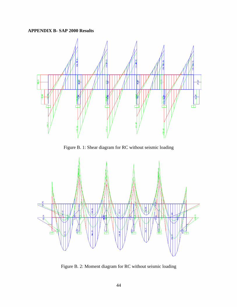
APPENDIX B- SAP 2000 Results
Figure B. 1: Shear diagram for RC without seismic loading
Figure B. 2: Moment diagram for RC without seismic loading

45
Figure B. 3: Shear diagram for RC with seismic loading
Figure B. 4: Moment diagram for RC with seismic loading

46
Figure B. 5: Shear diagram for PC with seismic loading
Figure B. 6: Moment diagram for PC with seismic loading

47
APPENDIX C - DATA
Figure C. 1: ASCE-7 Table 11.4.1 and 11.4.2

48
Figure C. 2: Table to determine the concrete steel ratio 𝜌

49
Figure C. 3: Table to determine bar size for the beam B3