EV100 Operating instructions (compressed images) · EV100 Operating Instructions - 3 - CERTIFICATE...
23
EV100 Electric Vehicle Supply Equipment Tester Operating Instructions Bracken Hill South West Industrial Estate Peterlee Co Durham SR8 2SW ENGLAND Tel: +44(0)191 5863511 www.seaward.co.uk [email protected] [email protected] Part Number 405A566 Revision 1 September 2015 © 2015 Seaward Electronic
Transcript of EV100 Operating instructions (compressed images) · EV100 Operating Instructions - 3 - CERTIFICATE...
EV100
Electric Vehicle Supply Equipment
Tester
Operating Instructions
Bracken Hill South West Industrial Estate Peterlee Co Durham SR8 2SW ENGLAND
Tel: +44(0)191 5863511 www.seaward.co.uk [email protected] [email protected] Part Number 405A566 Revision 1
September 2015 © 2015 Seaward Electronic

EV100 Operating Instructions
- 2 -
Contents Page
Certificate of Conformity 3
Limited Warranty and Limitation of Liability 4
Introduction 5
1 User notes 5
2 Safety notes 5
3 Accessories 6
3.1 Standard contents 6
3.2 Optional accessories 6
4 Identifying parts of the unit 6
5 Using the EV100 7
5.1 Power on the EV100 7
5.2 Battery condition check 7
5.3 Connecting the EV100 8
5.3.1 Type 1 tethered cable 8
5.3.2 Type 2 tethered cable 8
5.3.3 Type 2 direct connection 9
5.4 Standard auto sequence (excluding simulated EV faults) 9
5.5 Extended auto, including simulated EV faults 10
5.6 Vented system test 11
5.7 Insulation resistance test 11
5.8 RCD test 12
5.8.1 Single RCD trip time test 12
5.8.2 Automatic RCD test sequence 12
5.9 Auto shutdown 13
5.10 Warning messages 13
6 Seaward EVSEMobile App 15
6.1 EVSEMobile functions 15
6.2 Transferring data from the EV100 to EVSEMobile 15
6.3 Adding photographs to a record 16
6.4 Memory functions 16
6.4.1 PDF Export 17
6.4.2 Export all data 17
6.4.3 Import data 18
6.4.4 Clearing the memory 18
7 Specifications 19
8 Maintenance 20
8.1 Cleaning 20
8.2 Battery replacement 21
8.3 Replacing the fuse 21
8.4 Service and Calibration 21
8.5 Spare parts 21
Appendix 23

EV100 Operating Instructions
- 3 -
CERTIFICATE OF CONFORMITY
As the manufacturer of the apparatus listed, we declare under our sole responsibility that the product:
Seaward EV100
To which this declaration relates are in conformity with the relevant clauses of the following standard:
IEC 61010-1
Safety requirements for electrical equipment for measurement, control, and laboratory use – Part
1: General requirements.
IEC 61557-1,2,3,6,10
Electrical safety in low voltage distribution systems up to 1000V a.c. and 1500V d.c. – Equipment
for testing, measuring and monitoring of protective measures
IEC 61326
Electrical equipment for measurement, control and laboratory user-EMC Requirements
Performance: The instrument operates within specification when used under the conditions in the above
standards EMC and Safety Standards. The product identified above conforms to the requirements of Council Directive 2004/108/EC and 2006/95/EC.
Seaward Electronic Ltd is registered under BS EN ISO9001:2000 Certificate No: Q05356.
EV100 Operating Instructions
- 4 -
Limited Warranty & Limitation of Liability
SEAWARD Electronic Limited guarantees this product to be free from defects in material and workmanship under normal use and service for a period of 2 year, provided the instrument is serviced
and calibrated by authorised agent in accordance with the manufactures instructions. The period of warranty will be effective at the day of delivery. Manufacturer does not provide any warranty for the following:
• Any normal wear and tear;
• Errors or damage caused by: (i) misuse or not using your product in accordance with the user guide,
such as if the product has been exposed to moisture, to dampness or to extreme thermal or environmental conditions or to rapid changes in such conditions, to corrosion, to oxidation, to spillage of food or liquid or to influence from chemical products, (ii) using your product with, or connecting it to, any product, accessory, software, or service not manufactured or supplied by
manufacturer, (iii) any products combined with your Product by a third party, (iv) damage or errors caused by hacking, cracking, viruses, or ot her malware, or by unauthorised access to services, accounts, computer systems or networks; or (v) other acts beyond manufacturer’s reasonable control.
This Warranty is not valid:
• If your product, or the software it runs on, has been (i) opened, modified, or repaired without manufacturer’s authorisation, or (ii) repaired with unauthorised spare parts;
• If you have not installed the latest software updates that are publicly available for your product within a reasonable time of their release; or
• If you refuse to give possession of the product to manufacturer for repair and investigation.
(c) Copyright 2015 All rights reserved. Nothing from this edition may be multiplied, or made public in any form or manner, either electronically, mechanically, by photocopying, recording, or in any manner, without prior written consent from SEAWARD Electronic Limited. This also applies to accompanying drawings and diagrams. Due to a policy of continuous development SEAWARD Electronic Limited reserves the right to alter the
equipment specification and description outlined in this publication without prior notice and no part of this publication shall be deemed to be part of any contract for the equipment unless specifically referred to as an inclusion within such contract.
EV100 Operating Instructions
- 5 -
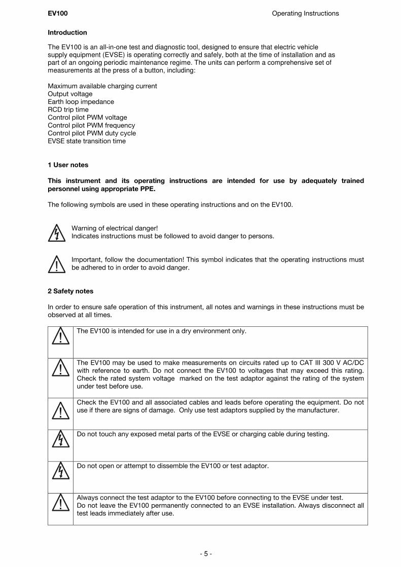
Introduction
The EV100 is an all-in-one test and diagnostic tool, designed to ensure that electric vehicle supply equipment (EVSE) is operating correctly and safely, both at the time of installation and as part of an ongoing periodic maintenance regime. The units can perform a comprehensive set of measurements at the press of a button, including: Maximum available charging current Output voltage Earth loop impedance RCD trip time Control pilot PWM voltage
Control pilot PWM frequency Control pilot PWM duty cycle EVSE state transition time
1 User notes
This instrument and its operating instructions are intended for use by adequately trained
personnel using appropriate PPE.
The following symbols are used in these operating instructions and on the EV100.
Warning of electrical danger! Indicates instructions must be followed to avoid danger to persons.
Important, follow the documentation! This symbol indicates that the operating instructions must
be adhered to in order to avoid danger.
2 Safety notes
In order to ensure safe operation of this instrument, all notes and warnings in these instructions must be observed at all times.
The EV100 is intended for use in a dry environment only.
The EV100 may be used to make measurements on circuits rated up to CAT III 300 V AC/DC with reference to earth. Do not connect the EV100 to voltages that may exceed this rating. Check the rated system voltage marked on the test adaptor against the rating of the system under test before use.
Check the EV100 and all associated cables and leads before operating the equipment. Do not use if there are signs of damage. Only use test adaptors supplied by the manufacturer.
Do not touch any exposed metal parts of the EVSE or charging cable during testing.
Do not open or attempt to dissemble the EV100 or test adaptor.
Always connect the test adaptor to the EV100 before connecting to the EVSE under test. Do not leave the EV100 permanently connected to an EVSE installation. Always disconnect all test leads immediately after use.

EV100 Operating Instructions
- 6 -
1. LCD Display 2. On/Off key 3. Auto test sequence key – triple action
a. Cable simulation setting (no test adaptor is connected) b. Auto test sequence (short press) c. Extended auto sequence (long press >3s)
4. Stop key 5. Insulation test key 6. NFC device position 7. RCD test key – dual action
a. Single trip time measurement (short press <2s) b. Auto test sequence (long press >2s)
8. Vent system test key 9. Test port 10. Protective cover
Where safe operation of the EV100 is no longer possible it should be immediately shut down and secured to prevent accidental operation. It must be assumed that safe operation is no longer possible:
• if the instrument or leads show visible signs of damage or
• the instrument does not function or
• after long periods of storage under adverse environmental conditions.
If the EV100 is used in a manner not specified by this document then the protection provided by the equipment may be impaired.
3 Accessories 3.1 Standard contents The Seaward EV100 test kit is supplied with the following items: 1 off EV 100 test instrument 1 off professional carry case 1 off Type 2 test adaptor
1 off Quick Reference Guide 6 off MN1500 (AA) 1.5v Batteries
3.2 Optional accessories
Type 1 test adaptor – Part number 405A950 4 Identifying parts of the unit
The numbering below refers to figure 1 and figure 2.
If the EV100 is being used to determine the presence or absence of hazardous voltages, always prove the operation of voltage measurement function before and after use by means of
a known voltage source or proving unit.
Figure 1 EV100 Front view
Figure 2 EV100 end view

EV100 Operating Instructions
- 7 -
LCD display
a. EVSE state - A/B/C/D/E/F
b. Charge cable rating
c. Type 1 latch status – latched/Un latched
d. EVSE contactor status – open/closed
e. Vented system test active
f. Maximum available charging current reported by EVSE
g. Earth loop impedance / RCD trip time / Insulation resistance result
h. Low battery indication
i. Message display
j. Caution – refer to operating instruction. When this icon is active, the operating instructions must be followed to avoid risk of danger.
k. NFC data available and ready for transfer
l. EVSE output active – charging voltage present
m. EVSE output voltage and phase
5 Using the EV100
5.1 Power On EV100
Press the ON/OFF key (2) to turn the EV100 on. Press and hold the ON/OFF key (2) for 2s to turn the EV100 off
5.2 Battery condition check The EV100 automatically performs battery condition checks whilst idle and during measurements. When the battery level is low, the battery symbol icon (h) will appear on the EV100 display. The EV100 will continue to function, however the batteries should be replaced.
Note: When the battery symbol icon is flashing all tests will be inhibited and the batteries
immediately must be replaced as described in section 8.2.
Figure 3 LCD display icons

EV100 Operating Instructions
- 8 -
5.3 Connecting the EV100
The EV100 can be used to simulate the presence of an Electric Vehicle (EV) connected to a charge point
via a Type 1 or Type 2 tethered cable. Alternatively, in the case of an EVSE fitted with a Type 2 socket, the EV100 can simulate connection of an EV via a detachable charging cable with a rating of 13A, 20A, 32A or 70A by simulating the coding resistor that would be present in a cable of that rating.
5.3.1 Type 1 tethered cable
1. Connect the Type 1 test adaptor to the
EV100 test port (9). The test adaptor plug and socket are keyed to ensure correct orientation. Rotate the plug until the key
ways are aligned before inserting. Do not force the plug into the socket. When the plug is fully inserted, rotate the outer ring to lock the connector in place.
2. Connect the test adaptor to the tethered
cable on the EVSE under test.
5.3.2 Type 2 tethered cable
Before connecting the test adaptor,
1. Press the Auto key (2) repeatedly until “Cable” connection type is shown in the message display (i).
2. Each press of the Auto key (2) will cause the message display (i) to toggle to the next available option.
Note: The selected simulation becomes the default setting and will
remain until changed using the Auto key (2), even if the EV100 is
powered off.
3. Connect the Type 2 test adaptor to the
EV100 test port (9). The test adaptor plug and socket are keyed to ensure correct orientation. Rotate the plug until the key ways are aligned before inserting. Do not force the plug into the socket. When the plug is fully inserted,
rotate the outer ring to lock the connector in place.
4. Connect the test adaptor to the tethered cable on the EVSE under test.

EV100 Operating Instructions
- 9 -
5.3.3 Type 2 direct connection
1. Press the Auto key (2) repeatedly until required connection type is
shown in the message display (i). 2. Each press of the Auto key (2) will cause the message display (i) to
toggle to the next available option.
Note: The selected simulation becomes the default setting and will
remain until changed using the Auto key (2) when no test adaptor
is connected, even if the EV100 is powered off.
Note: This feature can be used to confirm that the EVSE under test reduces the available current
to a value that does not exceed the rating of the charging cable. However, some EVSE will
not operate unless the charging cable rating is identical to the rated capacity of the EVSE.
3. Connect the Type 2 test adaptor to the EV100 test port (9). The test adaptor
plug and socket are keyed to ensure correct orientation. Rotate the plug until the key ways are aligned before inserting. Do not force the plug into the socket. When the plug is fully inserted, rotate the outer ring to lock the
connector in place.
4. Connect the test adaptor to the Type 2 socket on the EVSE under test.
5.4 Standard auto sequence (excluding simulated EV faults)
Note: If the Stop key (4) is pressed at any point in a test sequence, all test results up to that point
in the sequence are transferred to the on-board NFC device and are available for transfer
to the Seaward EVSEMobile App.
1. Connect the EV100 to the EVSE under test as described above in 5.3.
2. Press and release the Auto key (2) within 2s
• If the connection type is a Type 1 tethered cable, the charging cable latch position is shown by the display
icon (c). If the latched is opened at any point during the test sequence, the sequence will be terminated.

EV100 Operating Instructions
- 10 -
• If the connection type is a Type 2 tethered cable, the
cable rating is shown by the display icon (b).
• The automated test will measure the PWM signal from the EVSE and display the maximum
available current, Imax, communicated by the PWM duty cycle. A tick/cross is shown next to the
Imax value to indicate whether the PWM measured values are within the limits specified in
section 5.10.
• The EV100 will request charge current from the EVSE under test to drive it into state C.
Note: The EV100 will wait for a period of 60s for a response from the EVSE. If the EVSE does
not output a control pilot signal the EV100 will timeout and a warning message is
displayed as shown in section 5.10
• The display icon (a) will show state C, the contactor
icon (d) will change to the closed position and the message display (i) will show “charge.”
• The voltage supplied by the EVSE is shown by the
display read out (m). A tick/cross is shown next to the voltage measurement to indicate whether the measured values are within the limits specified in section 5.10.
• In the case of a three-phase system, each phase to earth voltage is measured. At the end of the test sequence the voltage display (m) will continually cycle through the three phase to earth voltage and the phase indicator will indicate the phase of the voltage
displayed i.e. φ1, φ2, φ3
• The EV100 will then measure the earth loop impedance, Zs, and display the result in the
display (g).
• When the test sequence is complete, the test results are
transferred to the on-board NFC.
• If all measured values are within the limits specified in section
5.10, a tick and sequence pass result is shown in the message display.
• The NFC display icon (k) appears when data is ready for
transfer to the Seaward EVSEMobile App.
5.5 Extended auto, including simulated EV faults If a fault occurs within an EV during the charge cycle, a correctly functioning EVSE will detect the presence of a fault and open the contactor to terminate AC energy transfer to the vehicle. The EVSE must open the contactor within the mains off delay specified in section 7.10. The EV100 can simulate a number of fault conditions (diode short circuit, diode short to ground and diode open circuit) and measure the mains off delay.
1. Connect the EV100 to the EVSE under test as described above in 5.3.
2. Press and hold the Auto key (2) for >3s. The EV100 will bleep to confirm the extended sequence
has been selected

EV100 Operating Instructions
- 11 -
• The EV100 will first perform the test sequence described above in 5.4
• When the EV100 is ready to begin the simulated EV faults, the message display (i) will show “confirn” (confirm).
3. To proceed with the simulated EV faults, press the Auto key (3) or press the Stop key (4) to abort.
• The EV100 will send a request for charge to drive the EVSE to state C, apply the following series of faults and measure the time taken for the EVSE to disconnect the supply to the output.
Diode short circuit Diode short to ground Diode open circuit
• After each simulated fault, the EV100 will wait for the EVSE under test to recover to State C
before applying the next fault in the sequence.
Note: If the EVSE does not automatically recover, user intervention may be required before
it can be re-energised to State C.
• When the test sequence is complete, the test results are transferred to the onboard NFC device
• The NFC icon appears when data is ready for transfer to the Seaward EVSEMobile App
5.6 Vented system test
The EV100 can simulate a request for charge from an EV that requires ventilation during the charge
cycle. This feature can be used to confirm that the ventilation system is operating correctly.
1. Connect the EV100 to the EVSE under test as described above in 5.3.
2. Press the Vent test key (8) to simulate a request for charge
from an EV that requires ventilation.
3. To terminate the test, press the STOP key (4).
• The EV100 will measure the PWM values, output voltage and
the state transitions times
• When the test sequence is complete, the test results are transferred to the onboard NFC device
• The NFC icon appears when data is ready for transfer to the Seaward EVSEMobile App
5.7 Insulation resistance test
The EV100 can perform an insulation resistance measurement
using a test voltage of 500V dc. This test can be used to measure the insulation resistance between all live conductors and the protective earth conductor in an EVSE or charging cable. When used to test an EVSE, the voltage will only be applied up to the point in the circuit where open contactor is positioned.
Do not touch the cable or EVSE during an insulation test.
1. Connect the EV100 to the EVSE under test as described
above in 5.3.
2. Press the insulation test key (5).

EV100 Operating Instructions
- 12 -
• After a few seconds, the measured insulation resistance and actual test voltage are shown on the EV100 display.
• The measured data can be transferred to the EVSEMobile App when the NFC icon appears on the EV100 display.
Note: Some EVSE have components connected between live
conductors and protective earth that may result in a low
insulation resistance reading. A low reading may not be due to
an insulation failure.
5.8 RCD test The EV100 can be used to test the operation of the charge current interrupting device (CCID) and measure the disconnection time.
Note: If the EVSE under test is powered from an RCD protected supply, an RCD trip test may also
trip the supply RCD.
5.8.1 Single RCD trip time test
1. Connect the EV100 to the EVSE under test as described above in 5.3.
2. Press the CCID test key (7).
• The EV100 will drive the EVSE into state C to energise the output and then apply a fault current of 30mA
• When the RCD trips, the trip time shown in the display (g).
• The starting phase of the test currently alternates between 0° and 180° for each successive
press of the CCID key (7).
• The NFC icon appears when data is ready for transfer to the Seaward EVSEMobile App
5.8.2 Automatic RCD test sequence
The EV100 can automatically perform a complete sequence of trip time tests to check for nuisance tripping and ensure that the RCD operates correctly at the rated residual operating current and at five times the rated residual operating current. The sequence of tests and expected outcome is as follows:
Test current and phase Expected outcome
1 half rated current (15mA) / 0° RCD should not trip
2 half rated current (15mA) / 180° RCD should not trip
3 rated current (30mA) / 0° RCD should trip within 300ms
4 rated current (30mA) / 180° RCD should trip within 300ms
5 five time rated current (150mA) / 0° RCD should trip within 40ms
6 five time rated current (150mA) / 180° RCD should trip within 40ms
Note: After each RCD trip, the EVSE must re-initialise and there may be a delay while the EV100
waits for the EVSE to respond. When the EVSE is ready to continue you will see the EV100
display icon (a) change from State A to State B. If the EVSE does not recover within a period
of 60s, the EV100 will timeout and report that no control pilot (CP) signal is present.
• Press and hold the CCID test key (7) for >3s. The EV100 will beep to confirm the RCD sequence has been activated.
EV100 Operating Instructions
- 13 -
• The EV100 will display h RCD (half-current RCD test) and apply a fault current of 15mA starting
at 0°.
• The RCD should not trip during the 2s test and the EV100 display will show >2.00s
• The EV100 will display h RCD (half-current RCD test) and apply a fault current of 15mA starting
at 180°.
• The RCD should not trip during the 2s test and the EV100 display will show >2.00s
• The EV100 will display RCD (rated current RCD test) and apply a fault current of 30mA starting at
0°.
• The RCD should trip and the trip time is shown on the EV100 display. When the EV100 display
shows RESET, reset the RCD then press the CCID key (7) to continue.
• The EV100 will display RCD (rated current RCD test) and apply a fault current of 30mA starting at
180°.
• The RCD should trip and the trip time is shown on the EV100 display. When the EV100 display
shows RESET, reset the RCD then press the CCID key (7) to continue.
• The EV100 will display 5 RCD (5 times rated current RCD test) and apply a fault current of
150mA starting at 0°.
• The RCD should trip and the trip time is shown on the EV100 display. When the EV100 display
shows RESET, reset the RCD then press the CCID key (7) to continue.
• The EV100 will display 5 RCD (5 times rated current RCD test) and apply a fault current of
150mA starting at 180°.
• The RCD should trip and the trip time is shown on the EV100 display. When the EV100 display
shows RESET, reset the RCD.
• The sequence is now complete. If all of the six tests where satisfactory an overall pass results is shown.
• When the test sequence is complete, the test results are transferred to the onboard NFC device and when data is ready for transfer to the Seaward EVSEMobile App when the NFC icon appears.
5.9 Auto shutdown
The EV100 will automatically switch off after 3 minutes of inactivity to preserve the life of the internal battery supply. The auto shutdown period cannot be alerted by the user.
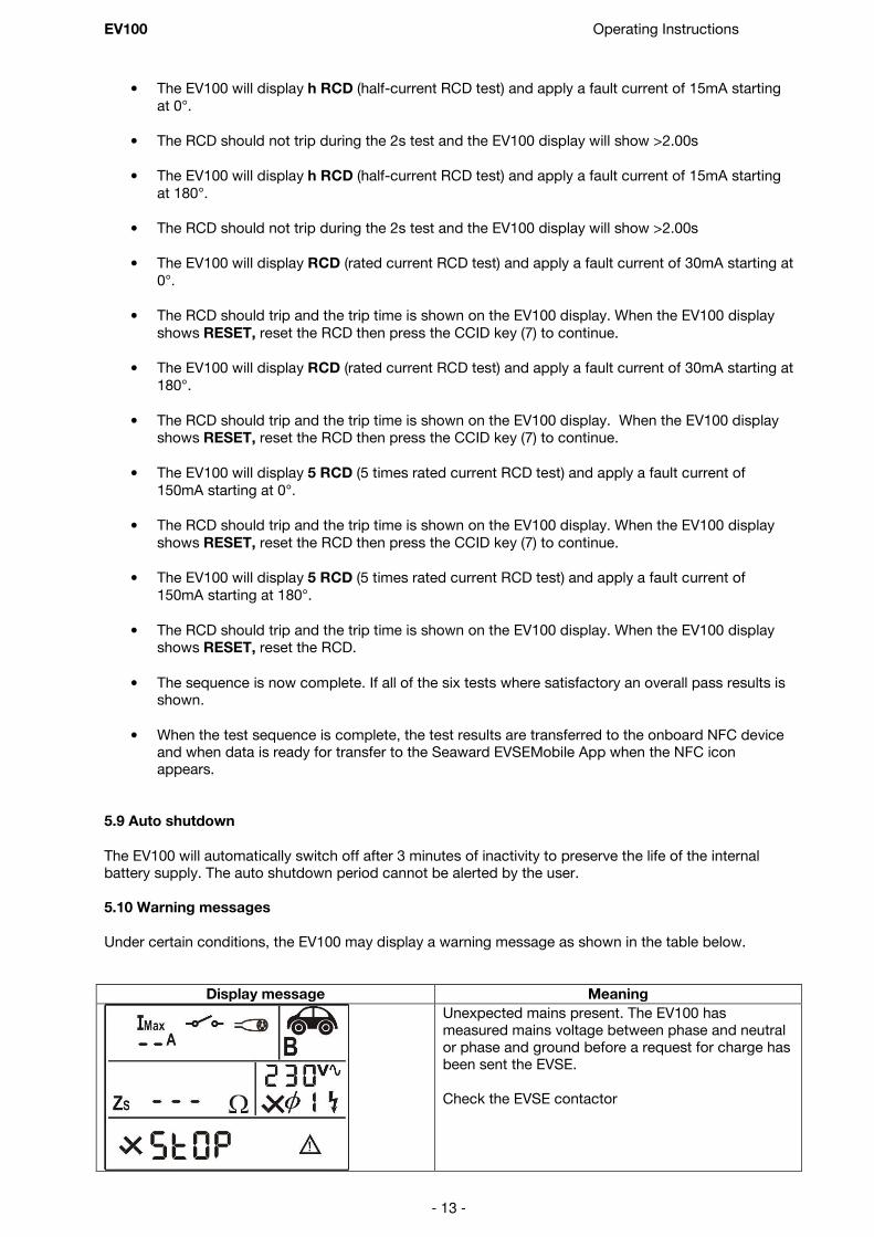
5.10 Warning messages
Under certain conditions, the EV100 may display a warning message as shown in the table below.
Display message Meaning
Unexpected mains present. The EV100 has measured mains voltage between phase and neutral or phase and ground before a request for charge has been sent the EVSE.
Check the EVSE contactor

EV100 Operating Instructions
- 14 -
No PWM signal is present on the control pilot line from the EVSE. This may not indicate a fault, if may simply be that the EVSE is not in state where is ready to charge.
Check that the EVSE is ready to charge and repeat the test.
The EV100 has been unable to determine the charging cable current capacity. The measured resistance is not one of the values shown in Appendix A.
There is no voltage present between phase and neutral or phase and earth when a request for charge is sent to the EVSE
The internal EV100 fuse is blown, preventing the unit from performing earth loop impedance
measurements on the EV100 supply. Check and replace the fuse as described in section 8.3

EV100 Operating Instructions
- 15 -
6 Seaward EVSEMobile App
6.1 EVSEMobile functions
In the home screen, the following functions are available:
1. Add new record - use to create a new test record for the EVSE under test.
2. Filter - view all records, pass records, fail records or bookmarked records.
3. Sort - the list of test records displayed can be sorted by ID Number, Site Name or Client Name.
4. Memory functions - records can be exported to PC, imported from PC or
all records can be deleted.
5. Settings – user name, product registration, language and help can be found here.
In the ‘add new record’ screen, the follow icons are available at the bottom on the display area:
Camera function used to take a photograph that can be stored with the test and inspection record
Save the record currently displayed
Add additional information about the EVSE, such as make, model, serial number, Modem IMEI. The current location is automatically displayed in the bottom right hand side of the display and is recorded when the test and inspection record is saved. Latitude and longitude data is available using the data export and PDF report functions.
6.2 Transferring data from the EV100 to EVSEMobile The result data is stored in a Near Field Communication (NFC) device mounted inside the front case of the EV100 where the NFC logo is located.
Note: The test data remains in the NFC device until it is overwritten by a new set of test results.
The data is not lost if the EV100 is switched off.
To transfer data from the EV100 to your Android device:
• Ensure that NFC is enabled on the Android device.
Note: S Beam and Android Beam may interfere with the operation of the
NFC and should be disabled.
• Open EVSEMobile on the Android device and press the + icon (1) to add a new record.
Note: If an NFC device is detected, the App will open automatically if it is
not already open. If the App is opened by detection of an NFC
device, the Android device must be removed and replaced on the
front of the EV100 to initiate data transfer.
• Place the Android device on top of the EV100 so that the NFC antenna in Android device if over the NFC logo on the EV100.

EV100 Operating Instructions
- 16 -
If the location of the NFC antenna in the Android device is unknown, you may need to experiment by moving the Android device slowly around the top surface of the EV100.
• Do not move the Android device during the data transfer. When the data has been
successfully transferred, a message will appear on the Android display showing “Transfer
Complete.”
• Enter an ID number and any other details required such as client name, site or location of EVSE
or Cable under test
Note: To save a record you must enter an ID Number. All other fields are optional.
• Choose the type or record to be created – EVSE Test or Cable Test using the drop down menu on the top right hand side of the display
It is possible to transfer multiple test results into a single test record e.g. an Auto Test followed by an RCD test followed by an insulation resistance test, building up a comprehensive test record for the EVSE under test. When all of the required tests have been completed and transferred to EVSEMobile, press the disk icon at the bottom of the display to save the record. Note: Once a record is saved, it will be locked against further edits.
6.3 Adding photographs to a record
Photographs can be added to a test record. This feature can be used to create a visual record of the
condition of the EVSE at the time and date of inspection and testing. To add a photograph to the record,
• Press the camera icon and this will open the camera on the Android device.
• Take the required photograph
• Accept the photograph, (how this is done varies from device to device but is commonly a tick or OK button)
A thumbnail of the photograph will appear in the bottom left hand window but the photograph is stored at the full camera resolution. 6.4 Memory functions Memory functions are used to import/export data and to clear all data in the database. The EVSEMobile App can export data in two different formats:
1. Individual test records can be exported to a PDF inspection and test certificate

EV100 Operating Instructions
- 17 -
2. The complete database can be exported as a single zip file. The exported file contains all photographs and a single XML format data file containing all test data. The XML file can be opened with Microsoft Excel and the results data will automatically be sorted into headed columns.
Exported data can be sent to a number of destinations providing a convenient means of transferring data from the test site back to the office for analysis and reporting.
6.4.1 PDF Export From the home screen
• Tap on the required test record to open the record.
• Select PDF report
• You can enter your own file name or simply press Export to use the default name consisting of the date and time of the export
• Select the required destination from “Send database to:”
6.4.2 Export all data
To export all records in a single file
• go to the home screen
• click on the disk icon (4) to open the memory options
• Click on Export and a pop up window will appear asking for a Name of export file.
• You can enter your own file name or simply press Export to use the default name consisting of the date and time of the export
• Select the required destination from “Send database to:”
EV100 Operating Instructions
- 18 -
Note: A monthly subscription is required to enable the premium features within EVSEMobile. This
includes data import/export and generating PDF certificates. There are no restrictions on the amount of usage once an active subscription is in place. Follow the onscreen instruction to subscribe.
The subscription can be cancelled at any point via Google Play and no further charges will apply.
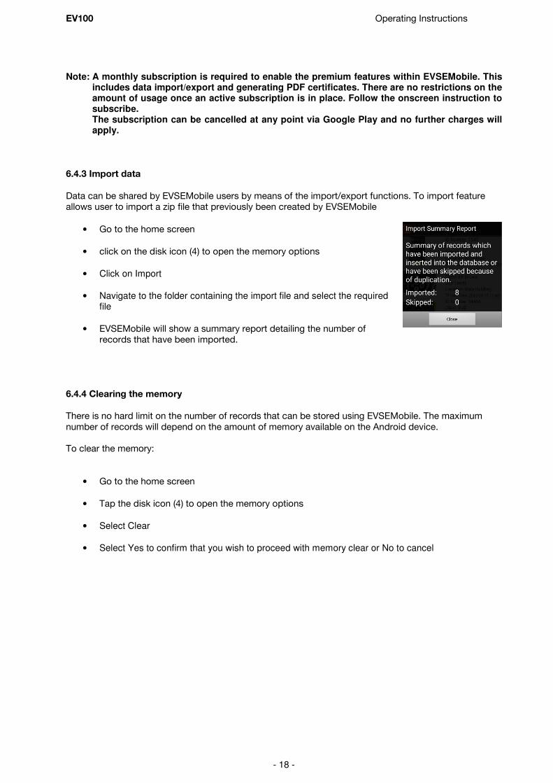
6.4.3 Import data
Data can be shared by EVSEMobile users by means of the import/export functions. To import feature allows user to import a zip file that previously been created by EVSEMobile
• Go to the home screen
• click on the disk icon (4) to open the memory options
• Click on Import
• Navigate to the folder containing the import file and select the required file
• EVSEMobile will show a summary report detailing the number of records that have been imported.
6.4.4 Clearing the memory
There is no hard limit on the number of records that can be stored using EVSEMobile. The maximum
number of records will depend on the amount of memory available on the Android device. To clear the memory:
• Go to the home screen
• Tap the disk icon (4) to open the memory options
• Select Clear
• Select Yes to confirm that you wish to proceed with memory clear or No to cancel

EV100 Operating Instructions
- 19 -
7 Specifications
7.1 Insulation Resistance
Display Range 0.01MΩ to 19.9MΩ
Measurement Range 0.10MΩ to 19.9MΩ
Accuracy +/- 5% +/- 5 digits
Resolution 0.01MΩ maximum
Open Circuit Test Voltage 500V dc -0% +20%
Voltage Indication +/- 5%
Test current >1mA into
Short Circuit Test Current <2mA
Number of Measurements Minimum of 1000 per IEC61557-2
Circuitry Protection Test inhibited if ≥ 30V AC or DC at inputs
7.2 Voltage measurement
Display range 0.0V – 300V AC
Measurement range 0.0V – 300V AC
Resolution 1V maximum
Accuracy ±(5%+2digit)
Frequency range 45Hz to 65Hz
7.3 Control Pilot PWM Measurements
Voltage range ±14v DC
Voltage resolution 0.1V
Frequency range 940 Hz to 1040 Hz
Frequency resolution 1Hz
Duty cycle range 2% to 98%
Resolution 1%
Response time range 1ms to 10s
Resolution 1ms
7..4 Earth Loop Impedance (Non trip)
Supply voltage 195V – 253V 45Hz to 65Hz
Nominal Test current <15mA (will not trip 30mA RCD)
Display range 1Ω - 1.6kΩ
Resolution 1Ω maximum
Measurement range 4Ω - 1.6kΩ
Accuracy ±5% ± 1 digit (4Ω - 1.6kΩ )
7.5 RCD trip time
Supply voltage 195V – 253V 45Hz to 65Hz
Test current (rms) 30mA sinusoidal
Test current accuracy -0% +10% at I∆n and 5I∆n
-10% +0% at ½ I∆n
Trip time ranges 40ms to 2000ms
Time measurement accuracy ±5% ± 2 digits
Available tests ½ I∆n , I∆n, 5 I∆n
EV100 Operating Instructions
- 20 -
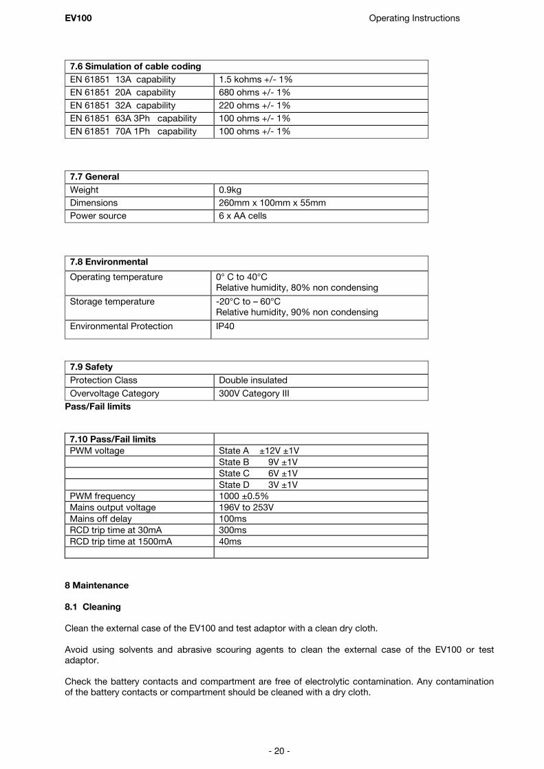
7.6 Simulation of cable coding
EN 61851 13A capability 1.5 kohms +/- 1%
EN 61851 20A capability 680 ohms +/- 1%
EN 61851 32A capability 220 ohms +/- 1%
EN 61851 63A 3Ph capability 100 ohms +/- 1%
EN 61851 70A 1Ph capability 100 ohms +/- 1%
7.7 General
Weight 0.9kg
Dimensions 260mm x 100mm x 55mm
Power source 6 x AA cells
7.8 Environmental
Operating temperature 0° C to 40°C Relative humidity, 80% non condensing Storage temperature -20°C to – 60°C Relative humidity, 90% non condensing
Environmental Protection
IP40
7.9 Safety
Protection Class Double insulated
Overvoltage Category 300V Category III
Pass/Fail limits
7.10 Pass/Fail limits
PWM voltage State A ±12V ±1V
State B 9V ±1V
State C 6V ±1V
State D 3V ±1V
PWM frequency 1000 ±0.5%
Mains output voltage 196V to 253V
Mains off delay 100ms
RCD trip time at 30mA 300ms
RCD trip time at 1500mA 40ms
8 Maintenance
8.1 Cleaning
Clean the external case of the EV100 and test adaptor with a clean dry cloth.
Avoid using solvents and abrasive scouring agents to clean the external case of the EV100 or test adaptor. Check the battery contacts and compartment are free of electrolytic contamination. Any contamination of the battery contacts or compartment should be cleaned with a dry cloth.

EV100 Operating Instructions
- 21 -
8.2 Battery replacement
Before opening the EV100 ensure that it is disconnected from all voltage! Electric shock danger!
Power the unit off.
Disconnect all the test leads from the unit Position the EV100 face down and undo the slotted captive screw in the battery compartment cover using a suitable tool. Remove the battery compartment cover.
Remove the discharged batteries from the compartment. Fit a new set of alkaline batteries. Relocate the battery cover over the battery compartment and fasten in position using the battery cover
captive screw.
8.3 Replacing the fuse
Ensure that the EV100 it is disconnected from all voltages before opening.
Replacement fuse specification is shown on the battery compartment cover on the rear of the EV100.
Power the unit off and disconnect the test adaptor cable from the unit.
Position the EV100 face down, undo the slotted captive screw in the battery compartment cover using a suitable tool and remove the battery compartment cover. Carefully lift one end of the fuse out of the fuse holder with the help of a flat bladed screwdriver and remove the defective fuse completely from of the fuse holder.
Insert a new fuse as described and specified by the text on the battery compartment cover. Ensure that the new fuse is seated and centred in the fuse holder. Relocate the battery cover over the battery compartment and fasten in position with the battery cover captive screw.
8.4 Service and Calibration
To maintain the specified accuracy of the measurement results, the instrument must be recalibrated at
regular intervals by either the manufacturer or an authorised Seaward Service Agent. We recommend a recalibration period of one year.
8.5 Spare parts
Seaward Part No. Type 1 test adaptor 405A950
Type 2 test adaptor 405A952
Carrying Case 388A951
500mA/1000V/10kA HBC 1¼’ fuse 27B137

EV100 Operating Instructions
- 22 -
For help or advice on Service and Calibration contact: Service Department Seaward Electronic Bracken Hill South West Industrial Estate
Peterlee Co Durham SR8 2SW England Tel: 0191 5878739 / 0191 5878737 Email: [email protected]

EV100 Operating Instructions
- 23 -
Appendix A
EVSE simulation options
Displayed message EV100 resistance Simulated EVSE connection
Cable N/A Tethered cable – Type 1 or Type 2
t2 70A 1k5 ohms ±1% Type 2 charging cable - 70A rated
t2 32A 680 ohms ±1% Type 2 charging cable - 32A rated
t2 20A 220 ohms ±1% Type 2 charging cable - 20A rated
t2 13A 100 ohms ±1% Type 2 charging cable - 13A rated