EV-PLUG-16/63A - FCI Electronics Interconnection Solutions
17
FCI MVL Division O WE R S 3 P . Power S upply S afe S olutions EV-PLUG-16/63A Charge plug 16A – 63A 2010 FCI COPYRIGHT
Transcript of EV-PLUG-16/63A - FCI Electronics Interconnection Solutions

FCI MVL Division
OWERS3P .Power Supply Safe Solutions
EV-PLUG-16/63A
Charge plug 16A – 63A 2010
FCI COPYRIGHT

2FCI – MVL 2010 FCI COPYRIGHT
Introduction
FCI has been launching several innovative high power connectors, named:
These are developed to meet the booming demand for high performance but cost effective high power interconnections from virtually all automotive OEM worldwide starting with Electric Vehicle (EV) programs scheduled for launch in 2010/11
Building on FCI Motorized Vehicles in-depth experience and expertise in the automotive sector, the new High power Interconnect and charge plugs incorporate a serie of ground- breaking features that reflect the unique challenges presented by EV and HEV applications, along with the requirement to keep size, weight and cost to a minimum.
OWER S3P .OWER S3P .Power Supply Safe Solutions

3FCI – MVL 2010 FCI COPYRIGHT
Charge plug applications
EVSE = Electric Vehicle Supply Equipment
Since May 2010, standardization committees have agreed on these product designations.They will be used from now on by all parties involved in charge plug business
OUT LETEVSE TERMINOLOGY
SAE J1772 – 16/32A
IEC 62196-2-2–16/32/63A
Ren
ault
©
IEC 62196-2-1–16/32ASLOW CHARGE
AC current
SLOW & FAST CHARGE AC current
Example only AC/DC ‘Combo’
VERY FAST CHARGEWhich standard in future?
Example – CHAdeMO
4FCI – MVL 2010 FCI COPYRIGHT
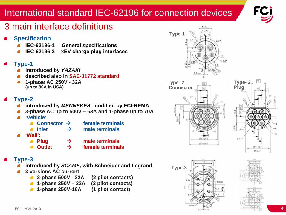
International standard IEC-62196 for connection devices 3 main interface definitions
SpecificationIEC-62196-1 General specificationsIEC-62196-2 xEV charge plug interfaces
Type-1introduced by YAZAKIdescribed also in SAE-J1772 standard1-phase AC 250V - 32A (up to 80A in USA)
Type-2introduced by MENNEKES, modified by FCI-REMA3-phase AC up to 500V – 63A and 1-phase up to 70A‘Vehicle’
Connector
female terminalsInlet
male terminals‘Wall’:
Plug
male terminalsOutlet
female terminals
Type-3introduced by SCAME, with Schneider and Legrand3 versions AC current
3-phase 500V - 32A (2 pilot contacts)1-phase 250V – 32A (2 pilot contacts)1-phase 250V-16A (1 pilot contact)
Type-1
Type-3
Type- 2 Connector
Type- 2 Plug

5FCI – MVL 2010 FCI COPYRIGHT
Interface choices and their combinations will vary across regions
Charge plugs product descriptions 3 interfaces – 4 product types

6FCI – MVL 2010 FCI COPYRIGHT
Line protection modes 1-2-3Domestic charging
Mode 1 (16A)No line protection
Mode 2 (16A)Portable line protection
CCID or BCB * * (Battery Connection Box)
Mode 3 (16A/32A)Connector to Plug jumper
Example here below Type 2 + Type-3
wall Electric Management Box

7FCI – MVL 2010 FCI COPYRIGHT
General view EV-PLUG-16/63A Vehicle side
InletMale terminals
ConnectorFemale terminals
Fully compatible with IEC62196-2-2

8FCI – MVL 2010 FCI COPYRIGHT
1st serial application on Renault ZOE (2012)

9FCI – MVL 2010 FCI COPYRIGHT
From IEC norm
Electrical circuit
No switch in plug
Differences versus SAE J1772 norm
No resistor in inlet
Usage of way according single or three phase

10FCI – MVL 2010 FCI COPYRIGHT
Inlet interface (male terminals) Connector interface (female terminals)
Interface definition vehicle side

11FCI – MVL 2010 FCI COPYRIGHT
Electrical 16, 32 or 63 A400 V - High voltage insulation protection1-phase, 2-phase, 3-phase possibilities (1-L3, N, PE)additional 2x 30V/2A signal terminals (control pilot)
Mechanical10 000 mating cycles Can handle 5 hot disconnects
EnvironmentalAmbient temperature – 40°c + 50°cIP67 (mated)IP67 (unmated inlet)
IEC 16/63A charge connector Specifications according to IEC 62196-2-2

12FCI – MVL 2010 FCI COPYRIGHT
Male terminal with front plastic protection on power
Terminal sizes: 6 mm for power and ground, 3 mm for signalsPlating : nickelCable crimping : hexagonal
Terminal systemFemale terminals with calibrated spring device to precisely control mating/un-mating forces
Spring
Contact beams
13FCI – MVL 2010 FCI COPYRIGHT
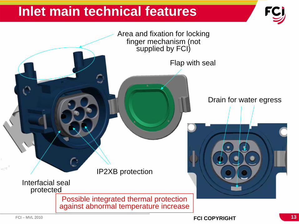
Flap with seal
Area and fixation for locking finger mechanism (not
supplied by FCI)
Interfacial seal protected
Inlet main technical features
Drain for water egress
IP2XB protection
Possible integrated thermal protection against abnormal temperature increase

14FCI – MVL 2010 FCI COPYRIGHT
Inlet general views
Cover (possible different 90°cable exit)
Rear viewFront view
Hole for locking finger
Flap closed (right or left side)

15FCI – MVL 2010 FCI COPYRIGHT
Inlet main dimensions

16FCI – MVL 2010 FCI COPYRIGHT
Interfacial sealing internal area protected
Hole for locking finger
Plug general view

17FCI – MVL 2010 FCI COPYRIGHT
THANK YOU !