Eurovac 04-1 (LAZ-04/1) - Eurogauge
36
Mess-, Regel- und Überwachungsgeräte für Haustechnik, Industrie und Umweltschutz Lindenstraße 20 DE-74363 Güglingen Telefon: +49(0)7135-102-0 Service: +49(0)7135-102-211 Telefax: +49(0)7135-102-147 E-Mail: [email protected] Internet: www.afriso.de Read instructions before using device! Observe all safety information! Keep instructions for future use! Version: 12.2007 ID No.: 854.001.0108 Operating Instructions Vacuum type leak detector Type: Eurovac 04-1 (LAZ-04/1) Product No.: 43660 Technical Approval of the German Institute for Building Technology: Z-65.22-4 Leak detectors Z-65.22-4
Transcript of Eurovac 04-1 (LAZ-04/1) - Eurogauge

Mess-, Regel- und Überwachungsgeräte für Haustechnik, Industrie und Umweltschutz Lindenstraße 20 DE-74363 Güglingen Telefon: +49(0)7135-102-0 Service: +49(0)7135-102-211Telefax: +49(0)7135-102-147E-Mail: [email protected] Internet: www.afriso.de
Read instructions before using device!
Observe all safety information!
Keep instructions for future use!
Version: 12.2007 ID No.: 854.001.0108
Operating Instructions
Vacuum type leak detector Type: Eurovac 04-1 (LAZ-04/1)
Product No.: 43660
Technical Approval of the German Institute for Building Technology: Z-65.22-4
Leak detectors Z-65.22-4

2 Eurovac 04-1 (LAZ-04/1)
Contents
1 About this manual ....................................................................................................4 1.1 Precautions...................................................................................................4 1.2 Explanation of notes, symbols and typeface................................................4
2 Safety.......................................................................................................................5 2.1 Intended use.................................................................................................5 2.2 Predictable incorrect application ..................................................................6 2.3 Safe handling................................................................................................6 2.4 Staff qualification ..........................................................................................7 2.5 Modifications to the product..........................................................................7 2.6 Usage of spare parts and accessories .........................................................7 2.7 Liability information.......................................................................................7
3 Product description ..................................................................................................8 3.1 Design...........................................................................................................8 3.2 System components, controls and display elements ...................................9 3.3 Function ......................................................................................................10 3.4 Operating modes ........................................................................................11 3.5 Application examples..................................................................................11
4 Specifications.........................................................................................................13 4.1 Approvals, tests and conformities ..............................................................14
5 Transportation and storage....................................................................................14 6 Mounting and commissioning ................................................................................14
6.1 Installation site ............................................................................................14 6.2 Leak detector ..............................................................................................15 6.3 Connection lines .........................................................................................15 6.4 Valve settings .............................................................................................18 6.5 Electrical connection...................................................................................19 6.6 Commissioning device................................................................................20
7 Operation ...............................................................................................................21 7.1 Alarm ..........................................................................................................22 7.2 Test.............................................................................................................22
8 Maintenance ..........................................................................................................23 8.1 Maintenance times .....................................................................................24 8.2 Maintenance activities ................................................................................24
9 Troubleshooting .....................................................................................................25 10 Shutting down and disposal...................................................................................25 11 Spare parts and accessories .................................................................................26
Eurovac 04-1 (LAZ-04/1) 3
12 Warranty................................................................................................................ 26 13 Copyright............................................................................................................... 27 14 Customer satisfaction ........................................................................................... 27 15 Addresses ............................................................................................................. 27 16 Appendix ............................................................................................................... 27
16.1 Certificate of expert ................................................................................... 27 16.2 List of substances for LAZ-04/1................................................................. 28 16.3 Approval documents .................................................................................. 31

About this manual
4 Eurovac 04-1 (LAZ-04/1)
1 About this manual This instruction manual is part of the product. Read this manual before using the product. Keep this manual during the entire service life of the product
and always have it readily available for reference. Always hand this manual over to future owners or users of the
product.
1.1 Precautions
WARNING TERM
Type and source of the danger is shown here.
Precautions to take in order to avoid the danger are shown here.
There are three different levels of warnings:
Warning term Meaning
DANGER Immediately imminent danger! Failure to observe the information will result in death or serious injuries.
WARNING Possibly imminent danger! Failure to observe the information may result in death or serious injuries.
CAUTION Dangerous situation! Failure to observe the information may result in minor or serious injuries as well as damage to property.
1.2 Explanation of notes, symbols and typeface
Symbol Meaning
Prerequisite for an activity
Activity consisting of a single step 1. Activity consisting of several steps
Result of an activity
• Bulleted list
Text Indication on a display
Highlighting Highlighting

Safety
Eurovac 04-1 (LAZ-04/1) 5
2 Safety 2.1 Intended use
The LAZ-04/1 leak detector for vacuum systems is a class 1 leak de-tector according to EN 13160-1. The LAZ-04/1 leak detector for vacuum systems may only be used to detect leaks in the containers (tanks) listed below which are not pressurised (i.e. operated under atmospheric conditions) and which are used for aboveground or underground storage of the liquids de-scribed below: • Single-walled tanks according to DIN 6608, 6616, 6619, 6624
and 6625, or according to an approved design with leak protec-tion lining which itself has an approved design.
• Double-walled tanks according to DIN 6608-2; 6616 design A; 6618-2; 6619-2; 6623-2; 6624-2 without leak detection fluid in the interstitial space (except a small volume in tanks according to DIN 6608).
• Double-walled tanks with design approval up to a height of 2.9 m or with a suction pipe leading to the bottom of the intersti-tial space.
• Double-walled tanks according to DIN 6608-2 with a layer of earth of at least 30 cm on top whose interstitial space is partially filled with leak detection fluid.
• Double-walled tanks for non-inflammable, water-polluting liquids as specified in the list of media in chapter 16.2, page 28.
• Double-walled tanks and tanks with an internal lining whose suitability for the use of leak detectors is demonstrated by a Technical Approval of the German Institute for Building Tech-nology issued by TÜV Nord.
The LAZ-04/1 leak detector may only be used for the tanks listed above and with the following liquids: • Inflammable liquids (mineral oil products) of danger class AIII. • Non-inflammable, water-polluting liquids as specified in the list
of media in chapter 16.2, page 28 and whose densities do not exceed the following densities, depending on the tank diameter and the tank height: Refer to table 1, page 6.
Please refer to the respective test certificates for the conditions for using the leak detectors with non-standard tanks with a mark of con-formity. Important: The interstitial space of the tank must be sufficiently re-sistant to the stored liquid.

Safety
6 Eurovac 04-1 (LAZ-04/1)
Table 1: Tank Ø or tank height and density
Tank accor-ding to
Tank Ø or tank height
Permissible density of stored medium
DIN 6608
DIN 6616
DIN 6624
≤ 2.9 m
≤ 2.5 m
≤ 2.0 m
≤ 1.6 m
≤ 1.25 m
≤ 1040 kg/m³
≤ 1200 kg/m³
≤ 1500 kg/m³
≤ 1880 kg/m³
≤ 1900 kg/m³
DIN 6618 Teil 2
≤ 15.95 m
≤ 12.75 m
≤ 9.585 m
≤ 1120 kg/m³
≤ 1470 kg/m³
≤ 1900 kg/m³
DIN 6619 ≤ 2.84 m
≤ 2.76 m
≤ 2.6 m
≤ 1.9 m
≤ 1060 kg/m³
≤ 1090 kg/m³
≤ 1160 kg/m³
≤ 1580 kg/m³
DIN 6623 ≤ 1.2 m ≤ 1900 kg/m³ The LAZ-04/1 leak detector creates a vacuum (approx. –400 mbar) in the interstitial chamber and generates an alarm when the pressure falls below the minimum level (approx. –340 mbar). Any use other than the use explicitly permitted in this instruction ma-nual in not permitted.
2.2 Predictable incorrect application The LAZ-04/1 leak detector must never be used in the following cases: • Hazardous area (potentially explosive atmosphere) • Use with any liquid other than the liquids mentioned above • Use with aggressive liquids which attack the connection hoses
and the leak detector.
2.3 Safe handling The LAZ-04/1 leak detector represents state-of-the-art technology and is made according to the pertinent safety regulations. Each de-vice is subjected to a function and safety test prior to shipping. Operate the LAZ-04/1 leak detector only when it is in perfect
condition. Always observe the operating instructions, all perti-nent local and national directives and guidelines as well as the

Safety
Eurovac 04-1 (LAZ-04/1) 7
applicable safety regulations and directives concerning the pre-vention of accidents.
WARNING
Severe burns or death due to mains voltage in the control unit.
Do not expose the control unit to water.
Interrupt the mains voltage supply before opening the control unit or before performing maintenance and cleaning work and make sure it cannot be switched on by accident.
Do not tamper with the control unit in any way whatsoever.
2.4 Staff qualification The product may only be mounted, commissioned, operated, main-tained, shut down and disposed of by qualified, specially trained staff. Electrical work may only be performed by trained electricians quali-fied in accordance with the local and national directives such as VDE.
2.5 Modifications to the product Changes or modifications made to the product by unauthorised per-sons may lead to malfunctions and are prohibited for safety reasons.
2.6 Usage of spare parts and accessories Usage of unsuitable spare parts and accessories may cause dam-age to the product. Use only genuine spare parts and accessories of the manufac-
turer (refer to chapter 11, page 26).
2.7 Liability information The manufacturer shall not be liable for direct or consequential dam-age resulting from failure to observe the technical instructions, guide-lines and recommendations. The manufacturer and the sales com-pany shall not be liable for costs or damages incurred by the user or by third parties in the usage or application of this device, in particular in case of improper use of the device, misuse or malfunction of the connection, malfunction of the device or of connected devices. The manufacturer or the sales company shall not be liable for damages resulting from any use other than the use explicitly permitted in this instruction manual. The manufacturer shall not be liable for misprints.

Product description
8 Eurovac 04-1 (LAZ-04/1)
3 Product description 3.1 Design
The LAZ-04/1 leak detector contains the following elements in an impact-resistant plastic housing: display elements and controls, a vacuum pump, a pressure switch, a printed circuit board with the electronic components for processing the output signal, a filter and three hose connections for the pneumatic connection to the intersti-tial space of the tank. The green pilot lamp lights up when mains voltage (230 V~) is available. The leak detector generates a constant vacuum in the interstitial space of the tank and generates alarm in case of a pressure drop. The alarm is indicated visually and audibly and is made available via a voltage-free relay contact (1 changeover contact).
Product description
Eurovac 04-1 (LAZ-04/1) 9
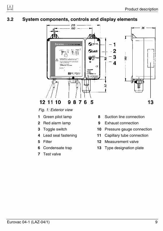
3.2 System components, controls and display elements
Fig. 1: Exterior view
1 Green pilot lamp 8 Suction line connection
2 Red alarm lamp 9 Exhaust connection
3 Toggle switch 10 Pressure gauge connection
4 Lead seal fastening 11 Capillary tube connection
5 Filter 12 Measurement valve
6 Condensate trap 13 Type designation plate
7 Test valve

Product description
10 Eurovac 04-1 (LAZ-04/1)
1 Fixing lug
2 Pump
3 Pressure switch
4 Terminals for electri-cal connection
5 PCB
Fig. 2: Interior view
3.3 Function The green pilot lamp lights up when mains voltage is available and the device is ready for operation. Via the suction line, the vacuum pump installed in the leak detector generates a vacuum within the range of approx. –400 mbar in the in-terstitial space of the tank. The pressure switch measures the pressure in the interstitial space via the capillary tube and keeps it at a constant level together with the vacuum pump. If a leak occurs in the tank's wall or in the leak protection lining (in the inner or outer wall of the tank) either above or below the level of the stored liquid or the ground water, and if this leak is greater than the pump's suction capacity, the vacuum will drop. If the pressure falls below the minimum pressure –340 mbar, the leak detector will trigger an alarm, i.e. the red alarm lamp and the audible alarm will be activated and the output relay will be energised. The audible alarm can be deactivated using the "Alarm tone" toggle switch after you have broken the seal. No alarm is triggered in case of a power failure. When mains power is available again, the device immediately resumes operation. If a leak has occurred in the meantime, this is indicated.
Product description
Eurovac 04-1 (LAZ-04/1) 11
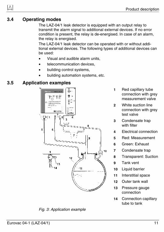
3.4 Operating modes The LAZ-04/1 leak detector is equipped with an output relay to transmit the alarm signal to additional external devices. If no error condition is present, the relay is de-energised. In case of an alarm, the relay is energised. The LAZ-04/1 leak detector can be operated with or without addi-tional external devices. The following types of additional devices can be used: • Visual and audible alarm units, • telecommunication devices, • building control systems,
• building automation systems, etc.
3.5 Application examples 1 Red capillary tube
connection with grey measurement valve
2 White suction line connection with grey test valve
3 Condensate trap with filter
4 Electrical connection
5 Red: Measurement
6 Green: Exhaust
7 Condensate trap
8 Transparent: Suction
9 Tank vent
10 Liquid barrier
11 Interstitial space
12 Outer tank wall
13 Pressure gauge connection
14 Connection capillary tube to tank
Fig. 3: Application example

Product description
12 Eurovac 04-1 (LAZ-04/1)
Fig. 4: LAZ-04/1 at vertical tank according to DIN 6618-2
1 Liquid barrier in suction line 8 White: Suction
2 Capillary tube 9 Green: Exhaust
3 Exhaust 10 Red: Measurement
4 DIN 6618-2 11 Measurement valve
5 Vacuum switch
6 Alarm buzzer
12 Protective pipe for under-ground installation
7 Vacuum buzzer 13 Condensate trap installed at lowest point of line
1 LAZ-04/1
2 AFRISO event reporting system
3 Internet
4 E-mail
5 Mobile phone
6 Fax 7 Telephone
Fig. 5: Remote leak reporting with AFRISO event reporting system

Specifications
Eurovac 04-1 (LAZ-04/1) 13
4 Specifications Table 2: Specifications
Parameter Value
General
Dimensions (W x H x D) 215 x 235 x 100 mm
Space requirements (W x H x D)
250 x 400 x 800 mm
Weight 1.7 kg
Emissions Min. 70 dB(A), A-evaluated sound level of the audible alarm at a distance of one metre
Output relay 1 changeover contact
Breaking capacity output relay
Max. 250 V, 2 A, resistive load
Relay contact fuse T 2 A
Switch point Alarm On -325 to -355 mbar
Switch point Alarm Off -380 mbar (point of reference, results from switching hysteresis)
Switch point Pump On -380 mbar (point of reference, results from switching hysteresis)
Switch point Pump Off -410 to -450 mbar
Hose connection Ø 5 mm
Connecting hose PVC hose 4 x 2 mm, 6 x 2 mm
Operating temperature range
Ambient -5 °C to +50 °C
Storage -10 °C to +60 °C
Supply
Supply voltage 230 V~
Rated power 95 VA
Mains fuse T 0.8 A
Electrical safety
Protection class II EN 60730

Transportation and storage
14 Eurovac 04-1 (LAZ-04/1)
Parameter Value
Protection IP 30 EN 60529
Electromagnetic compatibility (EMC)
Noise suppression According to EN 50081-1
Noise immunity According to EN 50082-2
4.1 Approvals, tests and conformities The LAZ-04/1 leak detector has the Qualification Approval 01/PTB No. III B/S 1432 and the Technical Approval of the German Institute for Building Technology PA-VI 62.1.07 and conforms to the EMC di-rective (89/336/EEC and 92/31/EEC) and the Low Voltage Directive (73/23/EEC and 93/68/EEC).
5 Transportation and storage
CAUTION
Damage to the device due to improper transportation.
Do not throw or drop the device.
Protect the device from wetness, humidity, dirt and dust.
CAUTION
Damage to the device due to improper storage.
Protect the device from wetness, humidity, dirt and dust.
6 Mounting and commissioning The leak detector may only be installed and commissioned by a spe-cialised company in accordance with § 19 l WHG.
6.1 Installation site • The leak detector must be mounted to an even, rigid and dry
wall at eye level. • The leak detector must be accessible and easy to oversee at all
times. • Choose an installation site that is as close as possible to the
tank to be monitored. The ambient temperature must be in range.

Mounting and commissioning
Eurovac 04-1 (LAZ-04/1) 15
• In the case of outdoor installation, the leak detector must be protected from direct atmospheric influences (use an IP 55 pro-tective housing).
• The leak detector must be mounted in such a way that it cannot be reached by water or splash water.
• Installation in damp rooms is not permitted. • The leak detector must not be installed in hazardous areas or in
access chambers of underground tanks.
6.2 Leak detector 1. Loosen the three housing screws at the front side of the leak de-
tector and remove the upper part of the housing. 2. Mount the housing base to the wall by means of the enclosed
dowels and screws (3 pieces DIN 96-4 x 30). 3. Connect the unit electrically as described in chapter 6.4,
page 18. 4. Refit the upper part of the housing and fasten it with the three
housing screws.
6.3 Connection lines 1. Connect the leak detector and the tank top be monitored as
shown in fig. 3, page 11, and fig. 4, page 12. You may use coloured plastic hoses 4 x 2 mm for lengths of up to 10 m. If the length exceeds 10 m, use steel pipes, copper pipes or plastic hoses with an inside diameter of 6 mm. The connection pipes or hoses must be pressure-proof, oil-, water- and weather-resistant. The connection lines must be permanently colour-coded: • Capillary tube made of hose: Red • Capillary tube made of pipe: Red rings at the ends of the pipe • Suction hose: White or transparent • Suction pipe: White rings at the ends of the pipe • Exhaust hose: Green
• Exhaust pipe: Green rings at the ends of the pipe 2. The connection lines must have a steady gradient from the leak
detector to the tank. Do not fit any shut-off elements. 3. If a steady gradient to the tank cannot be maintained, install
condensate traps at the lowest points. 4. In case of underground connection or outdoor installation of
plastic hoses, use weather-resistant protective pipes. 5. Connect the capillary tube to the capillary connection of the
tank.

Mounting and commissioning
16 Eurovac 04-1 (LAZ-04/1)
6. Connect the exhaust pipe or hose to the tank vent pipe. 7. Connect the suction line to the hose connection of the interstitial
space of the tank. 8. A liquid barrier must be installed in the suction hose. The liquid
barrier must be mounted vertically, e.g. at the manhole cover. In the case of aboveground, outdoor tanks, the connection lines must have an inside diameter of at least 6 mm (and a wall thickness of 2 mm if plastic pipes are used) and a slope of at least 4 %. 9. If you use hoses for the suction, capillary and exhaust lines, se-
cure all transition and connection points of the hoses with hose clamps that cover the entire circumference.
10. The connection lines must have the full cross section over the entire length, there must be no bends and indentations.
Do not fit any shut-off elements.
Tanks according to DIN 6608-2 with earth coverage whose inter-stitial space is still (partially) filled with leak detection fluid 1. Have a collecting container (bucket with at least 10 l capacity)
ready. 2. Disconnect the connection hose/tube of the leak detection fluid
container from the tank. 3. Collect the escaping leak detection fluid in the bucket. 4. Dismount the test cock, the connection line and the container for
the leak detection fluid with the plug-in probe. 5. Clean the 1" threaded sockets for the leak detection fluid con-
tainer and the test cock and mount/seal suitable adapters and hose connection pieces so that the suction hose and capillary tube of the LAZ-04/1 leak detector can be connected.
6. Provide a suction pump (min. capacity 1.5 m³/hour) to remove the liquid from the interstitial space of the tank. In addition, you need a carboy with a capacity of at least 10 l.
7. Insert two hoses into the carboy neck and seal them (suction hose pump, suction hose tank). Leave the hose connection for the capillary tube open for the the time being so that air can be admitted.
8. Suck the leak detection fluid from the interstitial space into the carboy until the liquid column becomes unstable and air is with-drawn.
Remove the maximum possible volume of liquid from the interstitial space. A specified minimum volume must be withdrawn in any event:

Mounting and commissioning
Eurovac 04-1 (LAZ-04/1) 17
Table 3: Minimum volume to be withdrawn
Tank capacity Minimum volume to be withdrawn
1-5 m³ 5 l
7-13 m³ 10 l
16-30 m³ 15 l
40-60 m³ 30 l
80-100 m³ 35 l 9. Connect vacuum gauges to the capillary tube connection. 10. Then keep withdrawing at a vacuum of -0.5 to -0.8 bar. 11. It is absolutely indispensable for the top area of the tank to con-
tain air. When the pumped volume decreases, interrupt the pumping process several times so that additional liquid can flow. If the suction volume becomes too small, alternating withdrawal via the capillary tube connection may prove to be more success-ful.
12. Always make sure to withdraw the maximum volume possible, but at least the volume specified in table 3, page 17 so that a sufficient air volume is created above the remaining liquid.
13. Dismount the pumping equipment. 14. Connect the suction hose, capillary tube and exhaust hose ac-
cording to the instructions in chapter 6.3, page 15, and commis-sion the leak detector.
Storage of non-inflammable, water-polluting liquids in double-walled tanks Refer to table 1, page 6, to make sure that the density of the
stored liquid does not exceed the specified limit value depend-ing on the tank type and tank diameter or tank height.
Connecting lines, liquid barrier, connection pieces and condensate traps must be resistant to the stored liquid and its vapours.

Mounting and commissioning
18 Eurovac 04-1 (LAZ-04/1)
6.4 Valve settings
Measurement valve at red capillary tube connection
Table 4: Settings of measurement valve
Valve setting Operating status
Normal operation
Test with pressure gauge
Not permitted
Not permitted
Test valve at white suction line connection
Table 5: Settings of test valve
Valve setting Operating status
Normal operation
Venting
Not permitted
Not permitted

Mounting and commissioning
Eurovac 04-1 (LAZ-04/1) 19
6.5 Electrical connection
Device is disconnected from mains and cannot be switched on. Observe the VDE regulations, the pertinent regulations concern-
ing the prevention of accidents, the operating instructions for the leak detector and the tank as well as all other applicable na-tional and local regulations.
Connect the leak detector directly to the 230 V supply network without a switch and without a plug.
Power supply Connect the leak detector to mains by means of a permanently in-stalled cable such as NYM-J 3 x 1.5 mm². 1. Route the power supply cable through the rubber cable gland at
the bottom right into the leak detector. 2. The phase must be connected to terminal L1 , the neutral con-
ductor to terminal N. The leak detector supply cable should have a separate fuse (max. 16 A).
1 Buzzer On/Off
2 Green lamp: Operation
3 Switch Alarm
4 Switch Pump
5 Mains fuse
6 230 V/50 Hz
7 0-230 V AC/DC, max. 2 A
8 Additional alarm
9 Relay fuse
10 Red lamp: Alarm 11 Pump: Buzzer
Fig. 6: Electrical connection
Output The output signal of the LAZ-04/1 leak detector is made available via a voltage-free relay contact (1 changeover contact). The relay cable must also be permanently installed. Route it
through the rubber cable gland at the top right into the leak de-tector. Connect it to the designated terminals ('relay contact').

Mounting and commissioning
20 Eurovac 04-1 (LAZ-04/1)
If no error condition is present, the relay is de-energised. In case of an alarm, the relay is energised. The relay contact is fused with a 2 A fuse (slow-blow).
CAUTION
Voltage peaks occur when inductive consumers are switched off. These peaks may considerably interfere with the function of electrical installations and destroy the switching contact.
Use commercially available standard RC combinations such as 0.1 µF/100 Ohm for inductive consumers.
6.6 Commissioning device
Basic vacuum The suction pump of the leak detector must not exceed a given ca-pacity (100 l/h). Therefore, the interstitial space should be evacuated to a vacuum of approximately –400 mbar before the leak detector is connected. Use an installation pump with a greater volume capacity for this purpose.
Leak test Check for leaks in the interstitial space. A slight pressure drop in the first hour is unavoidable. After that, there should be no noticeable pressure loss.
Adaptation Before the leak detector can be connected, the vacuum in the inter-stitial space must be reduced to –370 mbar. If the vacuum is greater when LAZ-04/1 is connected, the measuring system may be dam-aged or destroyed.
Commissioning
Leak detector is mounted and installed as per chapter 6.2, page 15.
Electrical connection as per chapter 6.4, page 18.
Both valves are in "Normal Operation" setting.
Measurement valve (red connection)
Test valve (white connection)
Interstitial space is pre-evacuated.

Operation
Eurovac 04-1 (LAZ-04/1) 21
Interstitial space is checked for leaks.
Vacuum in interstitial space is reduced to –370 mbar.
Leak detector is connected to interstitial space.
Liquid barrier is installed.
Leak detector housing is closed with screws. Switch on the power supply via the on-site mains fuse.
The green pilot lamp lights up.
The pump controller ensures the operating vacuum is available. If the operating vacuum drops below the "Alarm ON" switch point, the red alarm lamp lights up, the audible alarm is triggered and the relay is energised. The audible alarm can be muted via the toggle switch.
Once the set vacuum is reached, the pump of the leak detector switches off. Now the toggle switch must be set to the "ON" position and
lead-sealed.
The system is now ready for operation. Have the specialised company certify the installation, commis-
sioning and test of the leak detector using the form in chap-ter 16.1, page 27.
7 Operation The leak detector monitors double-walled tanks. If a leak occurs, the vacuum in the interstitial space drops and the leak detector gener-ates an alarm. The operation of the leak detector is therefore limited to its regular monitoring: • The green pilot lamp is on.
• The red alarm lamp is off. • The audible alarm is off. When the leak detector is tested (refer to chapter 7.2, page 22), the red alarm lamp must light up and the audible alarm must switch on.

Operation
22 Eurovac 04-1 (LAZ-04/1)
7.1 Alarm 1. In the case of an alarm, the audible alarm can be muted via the
toggle switch after you have broken the seal.
The red alarm lamp remains on. 2. Immediately notify the installation company.
The installation company must find the reason for the alarm. 3. When the problem has been fixed, you must perform a full func-
tion test as per chapter 7.2, page 22.
7.2 Test The function of the leak detector must be checked:
• After each commissioning • At least once per year by an expert
• After each alarm and fault repair
Test by simulation To guarantee operational reliability, perform a function check at least once per year by simulating a real alarm condition. A vent valve is connected to the white suction line connection. 1. Set the test valve (white connection) to "Vent".
The interstitial space of the tank is vented.
The vacuum in the interstitial space drops and the leak detector triggers an alarm.
2. Set the test valve (white connection) to "Normal Operation.
The vacuum in the interstitial space is regenerated.
The alarm signals must switch off automatically.
Test by measurement The lateral connection of the red capillary tube connection is pro-vided for connecting a vacuum gauge to test the system. 1. Connect the vacuum gauge (0-1000 mbar). 2. Set the measurement valve (red connection) to "Test".
The gauge indicates the vacuum in the interstitial space.

Maintenance
Eurovac 04-1 (LAZ-04/1) 23
3. Set the test valve (white connection) to "Vent".
The vacuum drops slowly.
4. Observe the gauge and record the pressure values at which the pump and the alarm signals are switched on.
1. Set the test valve (white connection) to "Normal Operation.
2. Compare the recorded values to the set values. 3. Set the measurement valve (red connection) to "Normal Opera-
tion".
4. Disconnect the vacuum gauge. 5. You must create a test report and keep it along with the other
documents for the leak detector. The pressure switch integrated in the leak detector may only be ad-justed and calibrated by the manufacturer or by trained staff.
8 Maintenance Maintenance must be performed by a specialised company unless the applicable local and/or national legislation and regulations explic-itly exempt you from this obligation. If required, close a maintenance agreement with a specialised
company (according to the German Water Protection Act § 19 l WHG or the regulations applicable in your country).
A leak detector is safety equipment that may only be repaired by the manufacturer in case of damage.

Maintenance
24 Eurovac 04-1 (LAZ-04/1)
8.1 Maintenance times
Table 6: Maintenance times
When Activity
Once per year
Simulation of an alarm condition, refer to chap-ter 7.2, page 22.
The condensate trap at the leak detector and the condensate traps installed in the hoses (if appli-cable) must be checked and drained. Replace the filter in the non-return valve and tightly screw the condensate trap back into the housing.
Perform suitable checks to ensure that the leak detector and its environment site are always clean, accessible and easy to oversee.
8.2 Maintenance activities
Replacing the mains fuse F1 1. Switch off the mains voltage. 2. Remove the upper part of the housing. 3. Remove the transparent cover from the mains fuse. 4. Replace the mains fuse F1: T 0.8 A. 5. Snap the transparent cover onto the mains fuse. 6. Refit the upper housing part and screw it to the base. 7. Switch on the mains voltage.
Replacing the relay fuse F2 1. Switch off the mains voltage. 2. Remove the upper part of the housing. 3. Remove the transparent cover from the mains fuse. 4. Replace the mains fuse F2: T 2 A. 5. Snap the transparent cover onto the mains fuse. 6. Refit the upper housing part and screw it to the base. 7. Switch on the mains voltage.

Troubleshooting
Eurovac 04-1 (LAZ-04/1) 25
9 Troubleshooting Repair work may only be performed by qualified, specially trained staff.
Table 7: Troubleshooting
Problem Possible reason Repair
Green pilot lamp is not on.
No mains voltage available.
Check mains voltage.
Check mains fuse.
Leak. Check hoses.
Vent valves are closed.
Close the filter chamber.
Red alarm lamp lights up.
- Notify the installation company.
Red alarm lamp lights up, but audi-ble alarm is not activated.
Seal is missing. Set toggle switch to "On" position and seal it.
Water in conden-sate trap.
- Drain condensate trap.
Filter polluted. - Replace filter.
Other malfunctions. - Send the device to the manufacturer.
10 Shutting down and disposal 1. Switch off mains voltage. 2. Dismount the device (see chapter 6, page 14, reverse sequence
of steps). 3. To protect the environment, this device must not be disposed of
together with the normal household waste. Dispose of the de-vice according to the local conditions and directives.
This device consists of materials that can be reused by recycling firms. The electronic inserts can be easily separated and the device consists of recyclable materials. If you do not have the opportunity to dispose of the used device in accordance with environmental regulations, please contact us for possibilities to dispose of it or to return it.

Spare parts and accessories
26 Eurovac 04-1 (LAZ-04/1)
11 Spare parts and accessories Product Product No.
LAZ-04/1 in protective housing with audible alarm 43665
Audible alarm, weatherproof 61012
Alarm lamp, weatherproof 61015
Condensate trap bar, triple 43692
PVC hose 4 x 2 mm, 100 m, red 43648
PVC hose 4 x 2 mm, 100 m, green 43649
PVC hose 4 x 2 mm, 100 m, transparent 43650
PVC hose 6 x 2 mm, 100 m, red 43662
PVC hose 6 x 2 mm, 100 m, green 43663
PVC hose 6 x 2 mm, 100 m, transparent 43664
Hose connector for 4 x 2 mm 20036
Pump for LAZ-04/1 43651
Pressure switch for LAZ-04/1 43653
Non-return valve 43605
Pilot lamp green 43661
Alarm lamp red 43658
Event reporting system AM1 90001
Event reporting system GSM Alarm 90002
Hose clamp 8 mm 810 000 0004
RC combination 0.1 µF/100 W 618 001 5100
Mains fuse T 0.8 A 960127 0800
Relay fuse T 2 A 960127 2000
Lead seal 06 15 000015
Wire for lead seal 9013670303B2
12 Warranty The warranty of the manufacturer for this product is 24 months after the date of purchase. This warranty shall be good in all countries in which this device is sold by the manufacturer or its authorised deal-ers.

Copyright
Eurovac 04-1 (LAZ-04/1) 27
13 Copyright The manufacturer retains the copyright to this manual. This manual may only be reprinted, translated, copied in part or in whole with the prior written consent of the manufacturer. We reserve the right to technical modifications with reference to the specifications and illus-trations in this manual.
14 Customer satisfaction Customer satisfaction is our prime objective. Please get in touch with us if you have any questions, suggestions or problems concerning your product.
15 Addresses The addresses of our worldwide representations and offices can be found on the Internet at www.afriso.de.
16 Appendix 16.1 Certificate of expert
This is to certify that the leak detector was installed, commissioned and function-tested in accordance with these operating instructions: Pump Off: _______mbar, Pump ON: _______mbar Alarm ON: _______mbar, Alarm OFF: _______mbar Pressure drop complete facility: ______mbar in _______minutes Tank according to DIN _______, year of manufacture: _______, li-tres: _________ Factory no.:___________, aboveground, underground Tank manufacturer:____________________________________ Specialised company:__________________________________ Owner: _____________________________________________ Location of system:____________________________________ Date:________________, Signature:____________________

Appendix
28 Eurovac 04-1 (LAZ-04/1)
16.2 List of substances for LAZ-04/1 # (ID #)
DIN 6601Designation of substance WDC
1 Used oils 3
2 Used motor and gearbox oils
3 Hydraulic oils HL and HLP DIN 51524, DIN 51525
4 Silicone oils
5 Lubricating oils DIN 51501, DIN 51511, DIN 51512 2
6 Thermal oils Q DIN 51522
7 Transformer oils (clophene)
8 Collected oil separator concentrate from compressor operation
9 Used cutting oil (drilling) emulsion
10 Cutting oils (drilling)
11 Spindle oils
12 Cutting oil
13 Cooling agents from grinding processes
14 (3393) Gasoil, flash point > 100 °C boiling point > 200 °C
15 (3224) Shale oils, flash point > 100 °C boiling point > 100 °C
16 (3230) Turpentine substit., flash point > 100 °C boiling point > 100 °C
17 (3176) Brake fluid, hydraulic, flash point > 100 °C
18 Glysatin, antifreeze 1
19 Ethylglycol, flash point > 100 °C 1
20 Diethylene glycol 1
21 Ethylene glycol
22 Methylglycol 1
23 Adipic acid dinitrile 1
24 Arsenic acid, aqueous solution 3
25 Benzotrichloride 1
26 Boric acid 1
27 Butylene phenol, liquid 1
Appendix
Eurovac 04-1 (LAZ-04/1) 29
# (ID #) DIN 6601
Designation of substance WDC
28 Calcium chlorate aqueous solution max. 65 %, flash point > 100 °C
2
29 Calcium hydroxide 1
30 Calcium nitrate 1
31 Diphenyles 2
32 Iron(III) chloride sulfate solution 1
33 Iron(III) chloride solution saturated 1
34 Iron(II) chloride solution saturated 1
35 Iron(II) sulfate solution saturated 1
36 (3193) Extracts, aromatic substances in alc. sol., boiling point > 100 °C
37 (3188) (3189)
Extracts, odorous substances in alc. solution, boiling point > 100 °C
38 Fluoroacetic acid 2
39 Formaldehydes 2
40 (443) (445)
Formaldehydes with methanol concentration < 15 %, flash point > 55° boiling point 96 °C
41 (607) Freon 2
42 (609) Frigen 2
43 Urea, dissolved 1
44 (3085) Resins dissolved in hydrocarbon without alcohol, flash point > 100 °C, boiling point > 100°
45 Potassium chloride 0
46 Potassium hydroxide aqueous solution max. 20 % 1
47 Potassium nitrate aqueous solutions 1
48 Potassium sulfide 2
49 Hydrocarbons and mixtures, flash point > 100 °C
50 Magnesium chlorate solutions 2
51 Magnesium nitrate solutions 1
52 Sodium acetate solutions 1
53 Sodium chloride solutions 0

Appendix
30 Eurovac 04-1 (LAZ-04/1)
# (ID #) DIN 6601
Designation of substance WDC
54 Sodium fluoride solutions 1
55 Sodium hydroxide solutions, flashpoint > 100 °C 1
56 Sodium nitrate 1
57 Sodium thiosulfate 0
58 Silver nitrate 3
59 Soap, concentrated 2
60 Soap solutions
61 (3183) Coal tar distillate, flash point > 100 °C boiling point > 100 °C
62 (3268) Coal tar naphtha, flash point > 100 °C boiling point > 100 °C
63 (3167) Tars, liquid flash point > 100 °C
65 (3226) Tinctures, medical, in alcohol solutions, flash point > 100 °C
66 Natural linseed oil 0
67 Natural olive oil 0
68 Natural caster oil 0
69 Natural wheat germ oil 0
70 Mineral brine 0

Appendix
Eurovac 04-1 (LAZ-04/1) 31
16.3 Approval documents

Appendix
32 Eurovac 04-1 (LAZ-04/1)
Appendix
Eurovac 04-1 (LAZ-04/1) 33

Appendix
34 Eurovac 04-1 (LAZ-04/1)

Appendix
Eurovac 04-1 (LAZ-04/1) 35
A
pp
end
ix 2
L
ist
of
sub
stan
ces
for
LA
Z-0
4/1
Ref
er to
cha
pter
16.
2, p
age
28.

Appendix
36 Eurovac 04-1 (LAZ-04/1)