European Technical Assessment ETA -08/0064 of 2018 03...
58
ETA-Danmark A/S Göteborg Plads 1 DK-2150 Nordhavn Tel. +45 72 24 59 00 Fax +45 72 24 59 04 Internet www.etadanmark.dk Authorised and notified according to Article 29 of the Regulation (EU) No 305/2011 of the European Parliament and of the Council of 9 March 2011 MEMBER OF EOTA European Technical Assessment ETA-08/0064 of 2018-03-27 I General Part Technical Assessment Body issuing the ETA and designated according to Article 29 of the Regulation (EU) No 305/2011: ETA-Danmark A/S Trade name of the construction product: FraP Angle Brackets Product family to which the above construction product belongs: Three-dimensional nailing plate (angle bracket for wood to wood and wood to concrete connections) Manufacturer: FraP Metall GmbH Triftstrasse 21B D-16348 Wandlitz Tel. +49 33 397 64 313 Fax +49 33 397 64 314 Internet www.frap-metall.de Manufacturing plant: UAB Toga FMG Obeniu k. Kietaviskiu sen. LT-21413 Elektrénu sav. This European Technical Assessment contains: 58 pages including 2 annexes which form an integral part of the document This European Technical Assessment is issued in accordance with Regulation (EU) No 305/2011, on the basis of: Guideline for European Technical Approval (ETAG) No. 015 Three Dimensional Nailing Plates, April 2013, used as European Assessment Document (EAD). This version replaces: The previous ETA with the same number issued on 2013-03-27 and expiry on 2018-03-27
Transcript of European Technical Assessment ETA -08/0064 of 2018 03...
ETA-Danmark A/S Göteborg Plads 1 DK-2150 Nordhavn Tel. +45 72 24 59 00 Fax +45 72 24 59 04 Internet www.etadanmark.dk
Authorised and notified according to Article 29 of the Regulation (EU) No 305/2011 of the European Parliament and of the Council of 9 March 2011
MEMBER OF EOTA
European Technical Assessment ETA-08/0064 of 2018-03-27
I General Part
Technical Assessment Body issuing the ETA and designated according to Article 29 of the Regulation (EU) No 305/2011: ETA-Danmark A/S
Trade name of the construction product:
FraP Angle Brackets
Product family to which the above construction product belongs:
Three-dimensional nailing plate (angle bracket for wood to wood and wood to concrete connections)
Manufacturer: FraP Metall GmbH Triftstrasse 21B D-16348 Wandlitz Tel. +49 33 397 64 313 Fax +49 33 397 64 314 Internet www.frap-metall.de
Manufacturing plant:
UAB Toga FMG Obeniu k. Kietaviskiu sen. LT-21413 Elektrénu sav.
This European Technical Assessment contains:
58 pages including 2 annexes which form an integral part of the document
This European Technical Assessment is issued in accordance with Regulation (EU) No 305/2011, on the basis of:
Guideline for European Technical Approval (ETAG) No. 015 Three Dimensional Nailing Plates, April 2013, used as European Assessment Document (EAD).
This version replaces:
The previous ETA with the same number issued on 2013-03-27 and expiry on 2018-03-27

Page 2 of 58 of European Technical Assessment no. ETA-08/0064, issued on 2018-03-27
Translations of this European Technical Assessment in
other languages shall fully correspond to the original
issued document and should be identified as such.
Communication of this European Technical
Assessment, including transmission by electronic
means, shall be in full (excepted the confidential
Annex(es) referred to above). However, partial
reproduction may be made, with the written consent of
the issuing Technical Assessment Body. Any partial
reproduction has to be identified as such.

Page 3 of 58 of European Technical Assessment no. ETA-08/0064, issued on 2018-03-27
II SPECIFIC PART OF THE
EUROPEAN TECHNICAL
ASSESSMENT
1 Technical description of product and
intended use
Technical description of the product
FraP Metall angle brackets, purlin ties and hold-downs
are one-piece non-welded, face-fixed three-
dimensional nailing plates to be used in timber to
timber connections. They are connected to construction
members made of timber or wood-based products with
ring shank nails according to EN 14592 or screws
according to ETA-11/0024 and to concrete or steel
members with bolts or metal anchors.
The three-dimensional nailing plates with a steel plate
thickness of up to 4 mm are made from steel DX51D +
Z275 according to EN 10346:2009 with Re 250
N/mm², Rm 330 N/mm² and A80 19% or from
stainless steel (1.4301, 1.4401, 1.4541, 1.4571 or
1.4016 according to EN 10088) with equivalent
characteristics. Dimensions, hole positions and typical
installations are shown in Annex B. FraP Metall three-
dimensional nailing plates are made from steel with
tolerances according to EN 10143.
2 Specification of the intended use in
accordance with the applicable EAD
The angle brackets are intended for use in making
connections in load bearing timber structures, as a
connection between a beam and a purlin, where
requirements for mechanical resistance and stability
and safety in use in the sense of the Basic Works
Requirements 1 and 4 of Regulation (EU) 305/2011
shall be fulfilled.
The connection may be with a single angle bracket or
with an angle bracket on each side of the fastened timber
member (see Annex A).
The static and kinematic behaviour of the timber
members or the supports shall be as described in Annex
B.
The wood members can be of solid timber, glued
laminated timber and similar glued members, or wood-
based structural members with a characteristic density
from 290 kg/m3 to 420 kg/m3. This requirement to the
material of the wood members can be fulfilled by using
the following materials:
• Structural solid timber classified to C14-C40
according to EN 338 / EN 14081,
• Glulam classified to GL24-GL36 according to
EN 1194 / EN 14080,
• LVL according to EN 14374,
• Parallam PSL,
• Intrallam LSL,
• Duo- and Triobalken,
• Cross laminated timber,
• Plywood according to EN 636
Annex B states the load-carrying capacities of the angle
bracket connections for a characteristic density of 350
kg/m3.
For different characteristic densities the lateral load-
carrying capacity of the screws or nails changes.
Therefore, for a characteristic density of less than 350
kg/m³ the characteristic load-carrying capacity of the
fasteners shall be reduced with the factor kdens.
2
kdensk
350
for 290 kg/m3 < ρk < 350 kg/m3
where ρk is the characteristic density of the timber in
kg/m3.
The load-carrying capacities for higher characteristic
densities may be taken as equal to the characteristic
capacities given in this document. Alternatively, the
load-carrying capacities of the fasteners may be
increased by the factor kdens, given by
0,5
kdensk
350
for 350 kg/m3 < ρk < 420 kg/m3
where ρk is the characteristic density of the timber in
kg/m3.
The design of the connections shall be in accordance
with Eurocode 5 or a similar national Timber Code. The
wood members shall have a thickness which is larger
than the penetration depth of the nails or screws into the
members.
The angle brackets, purlin ties and hold-downs are
primarily for use in timber structures subject to the dry,
internal conditions defined by service classes 1 and 2 of
Eurocode 5 and for connections subject to static or
quasi-static loading.
The angle brackets, purlin ties and hold-downs can also
be used in outdoor timber structures, service class 3,
when a corrosion protection in accordance with
Eurocode 5 is applied, or when stainless steel with
similar or better characteristic yield strength and
ultimate strength is employed.

Page 4 of 58 of European Technical Assessment no. ETA-08/0064, issued on 2018-03-27
The scope of the brackets regarding resistance to
corrosion shall be defined according to national
provisions that apply at the installation site considering
environmental conditions.
The provisions made in this European Technical
Assessment are based on an assumed intended working
life of the connectors of 50 years.
The indications given on the working life cannot be
interpreted as a guarantee given by the producer or
Assessment Body, but are to be regarded only as a
means for choosing the right products in relation to the
expected economically reasonable working life of the
works.

Page 5 of 58 of European Technical Assessment no. ETA-08/0064, issued on 2018-03-27
3 Performance of the product and references to the methods used for its assessment
Characteristic
Assessment of characteristic
3.1 Mechanical resistance and stability*) (BWR1)
Characteristic load-carrying capacity
See Annex B
Stiffness
No performance assessed
Ductility in cyclic testing
No performance assessed
3.2 Safety in case of fire (BWR2)
Reaction to fire
The brackets are made from steel classified as
Euroclass A1 in accordance with EN 13501-1
and Commission Delegated Regulation 2016/364
3.3 Hygiene, health and the environment (BWR3)
Influence on air quality
The product does not contain/release dangerous
substances specified in TR 034, dated March
2012 0**)
3.7 Sustainable use of natural resources (BWR7)
No performance assessed
3.8 General aspects related to the performance of
the product
The brackets have been assessed as having
satisfactory durability and serviceability when
used in timber structures using the timber species
described in Eurocode 5 and subject to the
conditions defined by service class 1, 2 and 3
Identification
See Annex A
*) See additional information in section 3.9 – 3.11.
**) In addition to the specific clauses relating to dangerous substances contained in this European Technical
Assessment, there may be other requirements applicable to the products falling within its scope (e.g. transposed
European legislation and national laws, regulations and administrative provisions). In order to meet the provisions of
the Construction Products Regulation, these requirements need also to be complied with, when and where they apply.

Page 6 of 58 of European Technical Assessment no. ETA-08/0064, issued on 2018-03-27
Safety principles and partial factors
The characteristic load-carrying capacities are based on
the characteristic values of the nail connections and the
steel plates. To obtain design values the capacities have
to be multiplied with different partial factors for the
material properties, in addition the nail connection with
the coefficient kmod.
According to EN 1990 (Eurocode – Basis of design)
paragraph 6.3.5 the design value of load-carrying
capacity can be determined by reducing the
characteristic values of the load-carrying capacity with
different partial factors.
Thus, the characteristic values of the load–carrying
capacity are determined also for timber failure FRk,H
(obtaining the embedment strength of nails subjected to
shear or the withdrawal capacity of the most loaded
nail, respectively) as well as for steel plate failure FRk,S.
The design value of the load–carrying capacity is the
smaller value of both load–carrying capacities.
mod Rk,H Rk,SRd
M,H M,S
k F FF min ;
Therefore, for timber failure the load duration class and
the service class are included. The different partial
factors M for steel or timber, respectively, are also
correctly taken into account.
3.9 Mechanical resistance and stability
See annex B for the characteristic load-carrying
capacity in the different directions F1 to F5.
The characteristic capacities of the angle brackets are
determined by calculation assisted by testing as
described in the EOTA Guideline 015 clause 5.1.2.
They should be used for designs in accordance with
Eurocode 5 or a similar national Timber Code.
No performance has been assessed in relation to
ductility of a joint under cyclic testing. The
contribution to the performance of structures in seismic
zones, therefore, has not been assessed.
No performance has been assessed in relation to the
joint’s stiffness properties - to be used for the analysis
of the serviceability limit state.
3.10 Aspects related to the performance of the
product
3.10.1 In accordance with ETAG 015 the angle brackets
have a zinc coating weight of min Z275. The steel
employed is pre-galvanized steel Grade DX51D +
Z275 according to EN 10346:2009 with Re 250 N/mm², Rm 330 N/mm² and A80 19% or from stainless steel (1.4301, 1.4401, 1.4541, 1.4571 or 1.4016 according to EN 10088) with equivalent characteristics.
3.11 General aspects related to the fitness for use of
the product
The nailing pattern used shall be either the maximum or
the minimum pattern as defined in Annex A.
Wane under the flaps of the angle bracket is allowed
provided it does not occur under the nails. Wane can
reduce the load-bearing capacity of the connection.
A gap between the connector and the timber member is
not allowed. However, where the angle bracket is used
for a connection between a beam and a column a gap of
5 mm is allowed.

Page 7 of 58 of European Technical Assessment no. ETA-08/0064, issued on 2018-03-27
4 Attestation and verification of
constancy of performance (AVCP)
4.1 AVCP system
According to the decision 97/638/EC of the European
Commission1, as amended, the system(s) of
assessment and verification of constancy of
performance (see Annex V to Regulation (EU) No
305/2011) is 2+.
5 Technical details necessary for the
implementation of the AVCP system, as
foreseen in the applicable EAD
Technical details necessary for the implementation of
the AVCP system are laid down in the control plan
deposited at ETA-Danmark prior to CE marking.
Issued in Copenhagen on 2018-03-27 by
Thomas Bruun
Managing Director, ETA-Danmark

Page 8 of 58 of European Technical Assessment no. ETA-08/0064, issued on 2018-03-27
Annex A
Product details definitions
Table A.1 Angle Brackets: Materials specification
Angle Bracket
type
Thickness
(mm)
Steel specification Coating
specification
242 070 055 2,5 DX51D / Stainless steel Z 275
242 070 955 2,5 DX51D / Stainless steel Z 275
242 090 065 2,5 DX51D / Stainless steel Z 275
242 090 965 2,5 DX51D / Stainless steel Z 275
242 100 090 3,0 DX51D / Stainless steel Z 275
242 100 990 3,0 DX51D / Stainless steel Z 275
242 072 055 2,0 DX51D / Stainless steel Z 275
242 072 955 2,0 DX51D / Stainless steel Z 275
242 092 065 2,0 DX51D / Stainless steel Z 275
242 092 965 2,0 DX51D / Stainless steel Z 275
242 102 090 2,5 DX51D / Stainless steel Z 275
242 102 990 2,5 DX51D / Stainless steel Z 275
242 050 035 2,5 DX51D / Stainless steel Z 275
242 090 041 2,5 DX51D / Stainless steel Z 275
243 129 040 3,0 DX51D / Stainless steel Z 275
243 149 040 3,0 DX51D / Stainless steel Z 275
243 409 040 3,0 DX51D / Stainless steel Z 275
243 416 040 3,0 DX51D / Stainless steel Z 275
243 608 040 2,0 DX51D / Stainless steel Z 275
243 609 061 2,0 DX51D / Stainless steel Z 275
243 609 062 2,0 DX51D / Stainless steel Z 275
243 905 054 2,5 DX51D / Stainless steel Z 275
243 915 965 2,5 DX51D / Stainless steel Z 275
243 948 048 3,0 DX51D / Stainless steel Z 275
243 948 076 3,0 DX51D / Stainless steel Z 275
243 948 116 3,0 DX51D / Stainless steel Z 275
241 446 200 2,0 or 2,5 DX51D / Stainless steel Z 275
241 664 200 2,0 or 2,5 DX51D / Stainless steel Z 275
241 665 200 2,0 or 2,5 DX51D / Stainless steel Z 275
241 666 200 2,0 or 2,5 DX51D / Stainless steel Z 275
241 661 200 2,0 or 2,5 DX51D / Stainless steel Z 275
241 884 200 2,0 or 2,5 DX51D / Stainless steel Z 275
241 886 200 2,0 or 2,5 DX51D / Stainless steel Z 275
241 888 200 2,0 or 2,5 DX51D / Stainless steel Z 275
241 116 200 2,0 or 2,5 DX51D / Stainless steel Z 275
241 118 200 2,0 or 2,5 DX51D / Stainless steel Z 275
241 111 200 2,0 or 2,5 DX51D / Stainless steel Z 275

Page 9 of 58 of European Technical Assessment no. ETA-08/0064, issued on 2018-03-27
Table A.2 Angle Brackets: Range of sizes
Angle Bracket
type
Height (mm)
vertical
Height (mm)
horizontal
Width
(mm)
Thickness
(mm)
Hole positions
(mm)
min max min max min max
242 070 055 69 71 69 71 55 56 ± 0,13 ± 0,5
242 070 955 69 71 69 71 53 56 ± 0,13 ± 0,5
242 090 065 89 91 89 91 65 65 ± 0,13 ± 0,5
242 090 965 89 91 89 91 61 65 ± 0,13 ± 0,5
242 100 090 104 106 104 106 89 91 ± 0,13 ± 0,5
242 100 990 104 106 104 106 84 91 ± 0,13 ± 0,5
242 072 055 69 71 68 71 54 56 ± 0,13 ± 0,5
242 072 955 69 71 68 71 53 56 ± 0,13 ± 0,5
242 092 065 89 91 89 91 64 66 ± 0,13 ± 0,5
242 092 965 89 91 89 91 61 66 ± 0,13 ± 0,5
242 102 090 104 106 104 106 89 91 ± 0,13 ± 0,5
242 102 990 104 106 104 106 84 91 ± 0,13 ± 0,5
242 050 035 49 51 49 51 34 36 ± 0,13 ± 0,5
242 090 041 89 91 89 91 37 40 ± 0,13 ± 0,5
243 129 040 88 91 116 118 39 41 ± 0,13 ± 0,5
243 149 040 89 91 139 141 39 41 ± 0,13 ± 0,5
243 409 040 88 91 39 41 39 41 ± 0,13 ± 0,5
243 416 040 152 156 39 41 38 40 ± 0,13 ± 0,5
243 608 040 79 84 59 63 39 41 ± 0,13 ± 0,5
243 609 061 83 85 59 61 55 61 ± 0,13 ± 0,5
243 609 062 83 85 59 61 55 61 ± 0,13 ± 0,5
243 905 054 89 91 49 51 54 56 ± 0,13 ± 0,5
243 915 965 89 91 148 150 62 64 ± 0,13 ± 0,5
243 948 048 89 91 47 49 47 49 ± 0,13 ± 0,5
243 948 076 89 91 47 49 75 77 ± 0,13 ± 0,5
243 948 116 89 91 47 49 115 117 ± 0,13 ± 0,5
241 446 200 39 41 39 41 55 61 ± 0,13 ± 0,5
241 664 200 59 61 59 61 37 41 ± 0,13 ± 0,5
241 665 200 59 61 59 61 49 51 ± 0,13 ± 0,5
241 666 200 59 61 59 61 57 61 ± 0,13 ± 0,5
241 661 200 59 61 59 61 95 101 ± 0,13 ± 0,5
241 884 200 79 81 79 81 37 41 ± 0,13 ± 0,5
241 886 200 79 81 79 81 55 61 ± 0,13 ± 0,5
241 888 200 79 81 79 81 75 81 ± 0,13 ± 0,5
241 116 200 99 101 99 101 55 61 ± 0,13 ± 0,5
241 118 200 99 101 99 101 75 81 ± 0,13 ± 0,5
241 111 200 99 101 99 101 95 101 ± 0,13 ± 0,5

Page 10 of 58 of European Technical Assessment no. ETA-08/0064, issued on 2018-03-27
Table A.3 Purlin Ties: Materials specification
Purlin Tie type Thickness
(mm)
Steel specification Coating
specification
170 170 x 34 2,0 DX51D / Stainless steel Z 275
210 210 x 34 2,0 DX51D / Stainless steel Z 275
250 250 x 34 2,0 DX51D / Stainless steel Z 275
290 290 x 34 2,0 DX51D / Stainless steel Z 275
330 330 x 34 2,0 DX51D / Stainless steel Z 275
370 370 x 34 2,0 DX51D / Stainless steel Z 275
uni 170 170 x 34 2,0 DX51D / Stainless steel Z 275
uni 210 210 x 34 2,0 DX51D / Stainless steel Z 275
uni 250 250 x 34 2,0 DX51D / Stainless steel Z 275
Table A.4 Purlin Ties: Range of sizes
Purlin Tie type Length (mm) Width (mm) Thickness
(mm)
Hole positions
(mm)
170 169 172 33,0 35,0 ± 0,13 ± 0,5
210 209 212 33,0 35,0 ± 0,13 ± 0,5
250 249 252 33,0 35,0 ± 0,13 ± 0,5
290 289 292 33,0 35,0 ± 0,13 ± 0,5
330 329 332 33,0 35,0 ± 0,13 ± 0,5
370 369 372 33,0 35,0 ± 0,13 ± 0,5
uni 170 169 172 33,0 35,0 ± 0,13 ± 0,5
uni 210 209 212 33,0 35,0 ± 0,13 ± 0,5
uni 250 249 252 33,0 35,0 ± 0,13 ± 0,5
Table A.5 Hold-downs: Materials specification
Hold-Down type Thickness
(mm)
Steel specification Coating
specification
hold-down 200, t = 2,0 mm 200 x 40 2,0
DX51D / Stainless
steel Z 275
hold-down 300, t = 2,0 mm 300 x 40 2,0
DX51D / Stainless
steel Z 275
hold-down 400, t = 2,0 mm 400 x 40 2,0
DX51D / Stainless
steel Z 275
hold-down 500, t = 2,0 mm 500 x 40 2,0
DX51D / Stainless
steel Z 275
hold-down 200, t = 4,0 mm 200 x 40 4,0
DX51D / Stainless
steel Z 275
hold-down 300, t = 4,0 mm 300 x 40 4,0 DX51D / Stainless
steel Z 275
hold-down 400, t = 4,0 mm 400 x 40 4,0 DX51D / Stainless
steel Z 275
hold-down 500, t = 4,0 mm 500 x 40 4,0 DX51D / Stainless
steel Z 275
Table A.6 Hold-downs: Range of sizes
Hold-Down type Length (mm) Width (mm)
Thickness
(mm)
Hole positions
(mm)
hold-down 200, t = 2,0 mm 199 202 39,0 41,0 ± 0,13 ± 0,5
hold-down 300, t = 2,0 mm 299 302 39,0 41,0 ± 0,13 ± 0,5
hold-down 400, t = 2,0 mm 399 402 39,0 41,0 ± 0,13 ± 0,5
hold-down 500, t = 2,0 mm 499 502 39,0 41,0 ± 0,13 ± 0,5
hold-down 200, t = 4,0 mm 199 202 39,0 41,0 ± 0,13 ± 0,5
hold-down 300, t = 4,0 mm 299 302 39,0 41,0 ± 0,13 ± 0,5
hold-down 400, t = 4,0 mm 399 402 39,0 41,0 ± 0,13 ± 0,5
hold-down 500, t = 4,0 mm 499 502 39,0 41,0 ± 0,13 ± 0,5

Page 11 of 58 of European Technical Assessment no. ETA-08/0064, issued on 2018-03-27
Table A.7 Fastener specification
Fastener Length Fastener type
Nail 4.0 mm 40 mm Ring shank nails according to EN 14592
with a profiled length of at least 30 mm
Screw 5.0 mm 50 mm
Self-tapping screws according to ETA-
11/0024
carbon steel or hardened stainless steel 1.4006
In the load-carrying-capacities of the nailed or screwed connection in Annex B the capacities
calculated from the formulas of Eurocode 5 are used assuming a thick steel plate when calculating
the lateral fastener load-carrying capacity. The characteristic withdrawal capacity of the nails and
screws has to be determined by calculation in accordance with EN 1995-1-1:2010, paragraph 8.3.2
and 8.7.2 (head pull-through is not relevant):
ax,Rk ax,k penF f d t for the nails
0,8
ef ax,k ef kax,Rk 2 2
a
n f dF
1,2 cos sin
for the screws
where:
nef Effective number of fasteners
fax,k Characteristic value of the withdrawal parameter in N/mm2
d Nail or screw diameter in mm
tpen Penetration depth of the profiled shank in mm; (4.0 x 40 mm: tpen 30 mm)
lef Penetration depth of the threaded part in mm (5.0 x 50 mm: lef 41 mm)
ρk Characteristic density of the timber in kg/m3
ρa Characteristic density of the timber in kg/m3 according to fax,k
Based on tests by Versuchsanstalt für Stahl, Holz und Steine, Karlsruhe Institute of Technology, the
characteristic value of the withdrawal resistance for the threaded nails may be calculated as:
fax,k = 50 ∙ 10-6 ∙ ρk2
Based on ETA-11/0024 the characteristic value of the withdrawal resistance and the characteristic
yield Moment for the screws d = 5.0 mm may be calculated as:
fax,k = 12,1 N/mm² 2,6
y,kM 0,15 600 d 5909 Nmm
The shape of the nail or screw directly under the head shall be in the form of a truncated cone with a
diameter under the head which fits or exceeds the hole diameter.
Bolts or Metal
Anchors diameter Correspondent hole diameter Bolts or Anchors type
12.0 mm Max. 2 mm larger than the bolt diameter See specification of the
manufacturer

Page 12 of 58 of European Technical Assessment no. ETA-08/0064, issued on 2018-03-27
FraP Metall Purlin Ties
Figure A. 1 Purlin Tie 171
Figure A. 2 Purlin Tie 211

Page 13 of 58 of European Technical Assessment no. ETA-08/0064, issued on 2018-03-27
Figure A. 3 Purlin Tie 251
Figure A. 4 Purlin Tie 291

Page 14 of 58 of European Technical Assessment no. ETA-08/0064, issued on 2018-03-27
Figure A. 5 Purlin Tie 331
Figure A. 6 Purlin Tie 371

Page 15 of 58 of European Technical Assessment no. ETA-08/0064, issued on 2018-03-27
Figure A. 7 Purlin Tie Uni 170
Figure A. 8 Purlin Tie Uni 210

Page 16 of 58 of European Technical Assessment no. ETA-08/0064, issued on 2018-03-27
Figure A. 9 Purlin Tie Uni 250
Figure A. 10 Typical installation of purlin ties
Page 17 of 58 of European Technical Assessment no. ETA-08/0064, issued on 2018-03-27
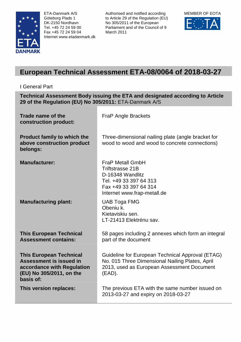
FraP Metall Hold-downs
Figure A. 11 Hold-Down 200, t = 2,0 mm
Figure A. 12 Hold-Down 300, t = 2,0 mm

Page 18 of 58 of European Technical Assessment no. ETA-08/0064, issued on 2018-03-27
Figure A. 13 Hold-Down 400, t = 2,0 mm
Figure A. 14 Hold-Down 500, t = 2,0 mm

Page 19 of 58 of European Technical Assessment no. ETA-08/0064, issued on 2018-03-27
Figure A. 15 Hold-Down 200, t = 4,0 mm
Figure A. 16 Hold-Down 300, t = 4,0 mm

Page 20 of 58 of European Technical Assessment no. ETA-08/0064, issued on 2018-03-27
Figure A. 17 Hold-Down 400, t = 4,0 mm
Figure A. 18 Hold-Down 500, t = 4,0 mm

Page 21 of 58 of European Technical Assessment no. ETA-08/0064, issued on 2018-03-27
Figure A. 19 Typical installation of hold-downs

Page 22 of 58 of European Technical Assessment no. ETA-08/0064, issued on 2018-03-27
FraP Metall Angle Brackets
Figure A. 20 Angle Bracket 242 070 055 70x70x55 (70 without rib)
Figure A. 21 Angle Bracket 242 070 955 70x70x55 (70 with rib)

Page 23 of 58 of European Technical Assessment no. ETA-08/0064, issued on 2018-03-27
Figure A. 22 Angle Bracket 242 090 065 90x90x65 (90 without rib)
Figure A. 23 Angle Bracket 242 090 965 90x90x65 (90 with rib)

Page 24 of 58 of European Technical Assessment no. ETA-08/0064, issued on 2018-03-27
Figure A. 24 Angle Bracket 242 100 090 105x105x90 (105 without rib)
Figure A. 25 Angle Bracket 242 100 990 105x105x90 (105 with rib)
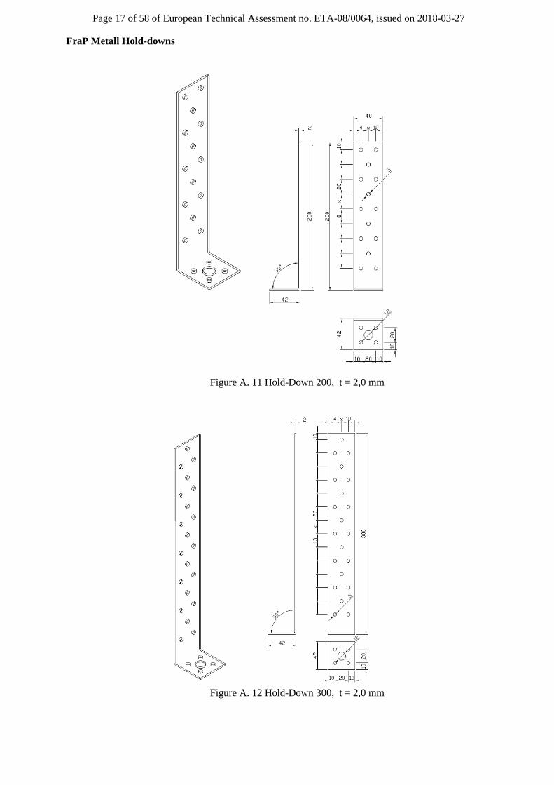
Page 25 of 58 of European Technical Assessment no. ETA-08/0064, issued on 2018-03-27
Figure A. 26 Angle Bracket 242 072 055 70x70x55
Figure A. 27 Angle Bracket 242 072 955 70x70x55

Page 26 of 58 of European Technical Assessment no. ETA-08/0064, issued on 2018-03-27
Figure A. 28 Angle Bracket 242 092 065 90x90x65
Figure A. 29 Angle Bracket 242 092 965 90x90x65

Page 27 of 58 of European Technical Assessment no. ETA-08/0064, issued on 2018-03-27
Figure A. 30 Angle Bracket 242 102 90 105x105x90
Figure A. 31 Angle Bracket 242 102 990 105x105x90

Page 28 of 58 of European Technical Assessment no. ETA-08/0064, issued on 2018-03-27
Figure A. 32 Angle Bracket 242 050 035 50x50x35
Figure A. 33 Angle Bracket 242 090 041 90x90x40

Page 29 of 58 of European Technical Assessment no. ETA-08/0064, issued on 2018-03-27
Figure A. 34 Angle Bracket 243 129 040 119x91x40
Figure A. 35 Angle Bracket 243 149 040 141x91x40

Page 30 of 58 of European Technical Assessment no. ETA-08/0064, issued on 2018-03-27
Figure A. 36 Angle Bracket 243 409 040 90x40x40
Figure A. 37 Angle Bracket 243 416 040 40x160x40

Page 31 of 58 of European Technical Assessment no. ETA-08/0064, issued on 2018-03-27
Figure A. 38 Angle Bracket 243 608 040 62x83x40
Figure A. 39 Angle Bracket 243 609 061 60x90x60

Page 32 of 58 of European Technical Assessment no. ETA-08/0064, issued on 2018-03-27
Figure A. 40 Angle Bracket 243 609 062 60x90x60
Figure A. 41 Angle Bracket 243 905 054 90x50x55

Page 33 of 58 of European Technical Assessment no. ETA-08/0064, issued on 2018-03-27
Figure A. 42 Angle Bracket 243 915 965 90x150x65
Figure A. 43 Angle Bracket 243 948 048 90x48x48

Page 34 of 58 of European Technical Assessment no. ETA-08/0064, issued on 2018-03-27
Figure A. 44 Angle Bracket 243 948 076 90x48x76
Figure A. 45 Angle Bracket 243 948 116 90x48x116

Page 35 of 58 of European Technical Assessment no. ETA-08/0064, issued on 2018-03-27
Figure A. 46 Angle Bracket 241 446 200 40x40x60
Figure A. 47 Angle Bracket 241 664 200 60x60x40

Page 36 of 58 of European Technical Assessment no. ETA-08/0064, issued on 2018-03-27
Figure A. 48 Angle Bracket 241 665 200 60x60x50
Figure A. 49 Angle Bracket 241 666 200 60x60x60

Page 37 of 58 of European Technical Assessment no. ETA-08/0064, issued on 2018-03-27
Figure A. 50 Angle Bracket 241 661 200 60x60x100
Figure A. 51 Angle Bracket 241 884 200 80x80x40

Page 38 of 58 of European Technical Assessment no. ETA-08/0064, issued on 2018-03-27
Figure A. 52 Angle Bracket 241 886 200 80x80x60
Figure A. 53 Angle Bracket 241 888 200 80x80x80

Page 39 of 58 of European Technical Assessment no. ETA-08/0064, issued on 2018-03-27
Figure A. 54 Angle Bracket 241 116 200 100x100x60
Figure A. 55 Angle Bracket 241 118 200 100x100x80

Page 40 of 58 of European Technical Assessment no. ETA-08/0064, issued on 2018-03-27
Figure A. 56 Angle Bracket 241 111 200 100x100x100
Figure A. 57 Typical installation of angle brackets

Page 41 of 58 of European Technical Assessment no. ETA-08/0064, issued on 2018-03-27
Annex B
Characteristic load-carrying capacities – Angle Brackets
Table B.1: Force F1 Column, 2 angle brackets / connection
Type Nail number
nV Nail number nh
F1,Rk [kN] (column)
Timber Steel
242 070 055
70 without rib 1,2,3 12,13,14,20,21,22 3,1 1,6
242 090 065
90 without rib 1,2 14,15,19,20,24,25 2,4 3,0
242 100 090
105 without rib 1,2,6,7,8,9,10 18,19,20,21,22,23,27,28,30,35,36 7,1 3,4
242 070 955
70 with rib 1,2,3 9,10,14,15,16 2,0 2,1
242 090 965
90 with rib 1,2 14,15,18,19,25,26 2,4 7,7
242 100 990
105 with rib 1,2,6,7 14,15,16,17,20,21,27,28 4,9 12,5
Table B.2: Force F1 Column, 1 angle bracket / connection
Type Nail number
nV Nail number nh
F1,Rk [kN] (column)
Timber Steel
242 070 055
70 without rib 1,2,3 12,13,14,20,21,22 1,5 0,8
242 090 065
90 without rib 1,2 14,15,19,20,24,25 1,2 1,5
242 100 090
105 without rib 1,2,6,7,8,9,10 18,19,20,21,22,23,27,28,30,35,36 3,5 1,7
242 070 955
70 with rib 1,2,3 9,10,14,15,16 1,0 1,0
242 090 965
90 with rib 1,2 14,15,18,19,25,26 1,2 3,8
242 100 990
105 with rib 1,2,6,7 14,15,16,17,20,21,27,28 2,4 6,3
Table B.3: Force F1 Purlin, 2 angle brackets / connection
Type Nail number nV Nail number nh F1,Rk [kN] (purlin)
Timber Steel
242 070 055
70 without rib 1,3,4,6,7 12,13,14,20,21,22 3,1 1,6
242 090 065
90 without rib 1,2,4,8,9,10,11 14,15,19,20,24,25 2,4 3,0
242 100 090
105 without rib 1,2,6,8,10,14,15 18,19,20,21,22,23,27,28,30,35,36 7,1 4,0
242 070 955
70 with rib 1,3,4,6 9,10,14,15,16 2,0 7,7
242 090 965
90 with rib 1,2,4,8,9 14,15,18,19,25,26 2,4 9,1
242 100 990
105 with rib 1,2,6,7,8,9,10,11 14,15,16,17,20,21,27,28 4,9 12,5

Page 42 of 58 of European Technical Assessment no. ETA-08/0064, issued on 2018-03-27
Table B.4: Force F1 Purlin, 1 angle bracket / connection
Type Nail number nV Nail number nh F1,Rk [kN] (purlin)
Timber Steel
242 070 055
70 without rib 1,3,4,6,7 12,13,14,20,21,22 1,5 0,8
242 090 065
90 without rib 1,2,4,8,9,10,11 14,15,19,20,24,25 1,2 1,5
242 100 090
105 without rib 1,2,6,8,10,14,15 18,19,20,21,22,23,27,28,30,35,36 3,5 1,7
242 070 955
70 with rib 1,3,4,6 9,10,14,15,16 1,0 1,0
242 090 965
90 with rib 1,2,4,8,9 14,15,18,19,25,26 1,2 3,8
242 100 990
105 with rib 1,2,6,7,8,9,10,11 14,15,16,17,20,21,27,28 2,4 6,3
Table B.5: Force F2/F3, 1 angle bracket / timber-timber connection
Art.-No.
Dimensions
lv x lh x b x t
Hole-No.
nv/nh
Nails Ø4,0x40 Screws Ø5,0x50
e1 F2,Rk/F3,Rk e1 F2,Rk/F3,Rk
[mm] [mm] [kN] [mm] [kN]
242 072 055
242 070 055 70x70x55x2,0
1,3,4,6,7 /
12,13,14,20,21,22 34,9 2,9 28,1 4,8
242 072 955
242 070 955 70x70x55x2,0
1,3,4,6 /
9,10,14,15,16 42,2 2,6 37,1 4,1
242 092 065
242 090 065 90x90x65x2,0
1,2,4,8,9,10,11/
14,15,19,20,24,25 49,3 3,6 47,2 5,3
242 092 965
242 090 965 90x90x65x2,0
1,2,4,8,9 /
14,15,18,19,25,26 44,3 2,7 34,6 4,6
242 102 090
242 100 090 105x105x90x2,5
1,2,6,8,10,14,15 /
18,19,20,21,22,23,27,
28,30,35,36
41,7 4,3 31,0 7,5
242 102 990
242 100 990 105x105x90x2,5
1,2,6,7,8,9,10,11 /
14,15,16,17,20,21,27,28 45,4 4,5 39,1 7,1
242 050 035 50x50x35x2,5 1,2 /
6,7,8,10 22,7 1,3 14,6 2,6
242 090 041 90x90x38x2,5 1,2,6,7 /
11,12,16,17,19,20 48,1 2,1 39,0 3,4
243 129 040 89x117x40x3,0
1,2,4,5 /
9,10,12,13,14,15,17,
18,20,21
35,0 2,4 21,5 4,6
243 149 040 90x140x40x3,0
1,2,4,5 /
9,10,12,13,14,15,17,18,
20,21,22,23
30,8 2,6 16,8 5,2
243 409 040 90x40x39x3,0 1,2,4,5,6,7 /
11,12,14,15 53,4 2,4 48,3 3,8
243 416 040 153x40x39x3,0
1,2,3,4,6,7,8,9,10,
11,13,14 /
15,16,18,19
100,0 2,9 100,0 4,1
243 608 040 80x60x40x2,0 1÷5 /
6÷10 40,0 4,2 32,0 3,5

Page 43 of 58 of European Technical Assessment no. ETA-08/0064, issued on 2018-03-27
Continuation of table B.5: Force F2/F3, 1 angle bracket / timber-timber connection
Art.-No.
Dimensions
lv x lh x b x t
Hole-No.
nv/nh
Nails Ø4,0x40 Screws Ø5,0x50
e1 F2,Rk/F3,Rk e1 F2,Rk/F3,Rk
[mm] [mm] [kN] [mm] [kN]
243 609 061 84x60x56x2,0 1,2,3,4,5,6,7,9 /
10,11,12,14,15,16 50,1 3,6 46,2 5,4
243 609 062 84x60x56x2,0 1,2,4,5,7 /
9,10,11,12,13 45,7 5,5 40,9 4,2
243 905 054 90x50x55x2,5 1,2,4,5,7,8,10,11 /
14,15,19,20 56,3 3,3 56,3 4,8
243 915 965 90x149x63x2,5
1,2,6,7 /
12,13,14,15,19,20,21,
22,23,25,26,27
12,7 4,3 7,6 7,1
243 948 048 90x48x48x3,0 1,2,4,5,6,7 /
10,11,13,14 53,4 2,5 51,7 3,7
243 948 076 90x48x76x3,0 1,2,3,6,7,8,9,10, 11,12 /
16,17,20,21 55,0 3,5 55,0 5,0
243 948 116 90x48x116x3,0
1,2,3,4,5,8,9,10,11,12,
13,15,16,17,18 /
22,23,24,25,29,30,31
56,7 6,8 56,7 9,7
241 446 200 40x40x56x2,0 1,2 /
6,7,9,10 15,2 2,3 8,3 4,0
241 664 200 60x60x38x2,0 1÷3 /
6÷10 24,4 1,4 15,2 2,7
241 665 200 60x60x50x2,0 1,3,4,5 /
9,10,11,14,15,16 25,2 2,7 17,5 4,9
241 666 200 60x60x58x2,0 1÷5 /
9÷16 24,6 3,1 16,4 5,7
241 661 200 60x60x96x2,0 1÷9 /
9÷28 24,2 7,8 16,7 13,5
241 884 200 80x80x38x2,0 1÷4 /
7÷12 35,2 1,6 26,4 2,8
241 886 200 80x80x56x2,0 1÷7 /
11÷20 34,1 3,5 25,5 6,1
241 888 200 80x80x76x2,0 1÷10 /
15÷28 33,6 5,9 25,7 10,1
241 116 200 100x100x56x2,0 1÷10 /
14÷26 46,1 4,7 36,3 8,0
241 118 200 100x100x76x2,0 1÷14 /
19÷36 44,9 7,5 36,0 12,5
241 111 200 100x100x96x2,0 1÷18 /
24÷46 42,2 11,3 37,3 17,3

Page 44 of 58 of European Technical Assessment no. ETA-08/0064, issued on 2018-03-27
Table B.6: Force F2/F3, 2 angle brackets / timber-timber connection
Art.-No.
Dimensions
lv x lh x b x t
Hole-No.
nv/nh
Nails Ø4,0x40 Screws Ø5,0x50
e1 F2,Rk/F3,Rk e1 F2,Rk/F3,Rk
[mm] [mm] [kN] [mm]
242 072 055
242 070 055 70x70x55x2,0
1,3,4,6,7 /
12,13,14,20,21,22 34,9 5,8 28,1 9,6
242 072 955
242 070 955 70x70x55x2,0
1,3,4,6 /
9,10,14,15,16 42,2 5,2 37,1 8,1
242 092 065
242 090 065 90x90x65x2,0
1,2,4,8,9,10,11/
14,15,19,20,24,25 49,3 7,2 47,2 10,6
242 092 965
242 090 965 90x90x65x2,0
1,2,4,8,9 /
14,15,18,19,25,26 44,3 5,4 34,6 9,2
242 102 090
242 100 090 105x105x90x2,5
1,2,6,8,10,14,15 /
18,19,20,21,22,23,27,
28,30,35,36
41,7 8,7 31,0 15,0
242 102 990
242 100 990 105x105x90x2,5
1,2,6,7,8,9,10,11 /
14,15,16,17,20,21,
27,28
45,4 9,0 39,1 14,2
242 050 035 50x50x35x2,5 1,2 /
6,7,8,10 22,7 2,6 14,6 5,2
242 090 041 90x90x38x2,5 1,2,6,7 / 11,12,16,17,19,20 48,0 4,2 39,0 6,8
243 129 040 89x117x40x3,0
1,2,4,5 /
9,10,12,13,14,15,17,
18,20,21
35,0 4,8 21,5 9,1
243 149 040 90x140x40x3,0
1,2,4,5 /
9,10,12,13,14,15,17,18,20,2
1,22,23
30,8 5,2 16,8 10,3
243 409 040 90x40x39x3,0 1,2,4,5,6,7 /
11,12,14,15 53,4 4,9 48,3 7,5
243 416 040 153x40x39x3,0
1,2,3,4,6,7,8,9,10,
11,13,14 /
15,16,18,19
100,0 5,8 100,0 8,2
243 608 040 80x60x40x2,0 1÷5 /
6÷10 40,0 4,2 32 7,1
243 609 061 84x60x56x2,0 1,2,3,4,5,6,7,9 /
10,11,12,14,15,16 50,1 7,2 46,2 10,8
243 609 062 84x60x56x2,0 1,2,4,5,7 /
9,10,11,12,13 45,7 5,5 40,9 8,4
243 905 054 90x50x55x2,5 1,2,4,5,7,8,10,11 /
14,15,19,20 56,3 6,7 56,3 9,5
243 915 965 90x149x63x2,5
1,2,6,7 /
12,13,14,15,19,20,21,
22,23,25,26,27
12,7 8,6 7,6 14,2
243 948 048 90x48x48x3,0 1,2,4,5,6,7 /
10,11,13,14 53,4 5,1 51,7 7,4
243 948 076 90x48x76x3,0 1,2,3,6,7,8,9,10, 11,12 /
16,17,20,21 55,0 7,0 55,0 10,0
243 948 116 90x48x116x3,0
1,2,3,4,5,8,9,10,11,12,
13,15,16,17,18 /
22,23,24,25,29,30,31
56,7 13,6 56,7 19,3
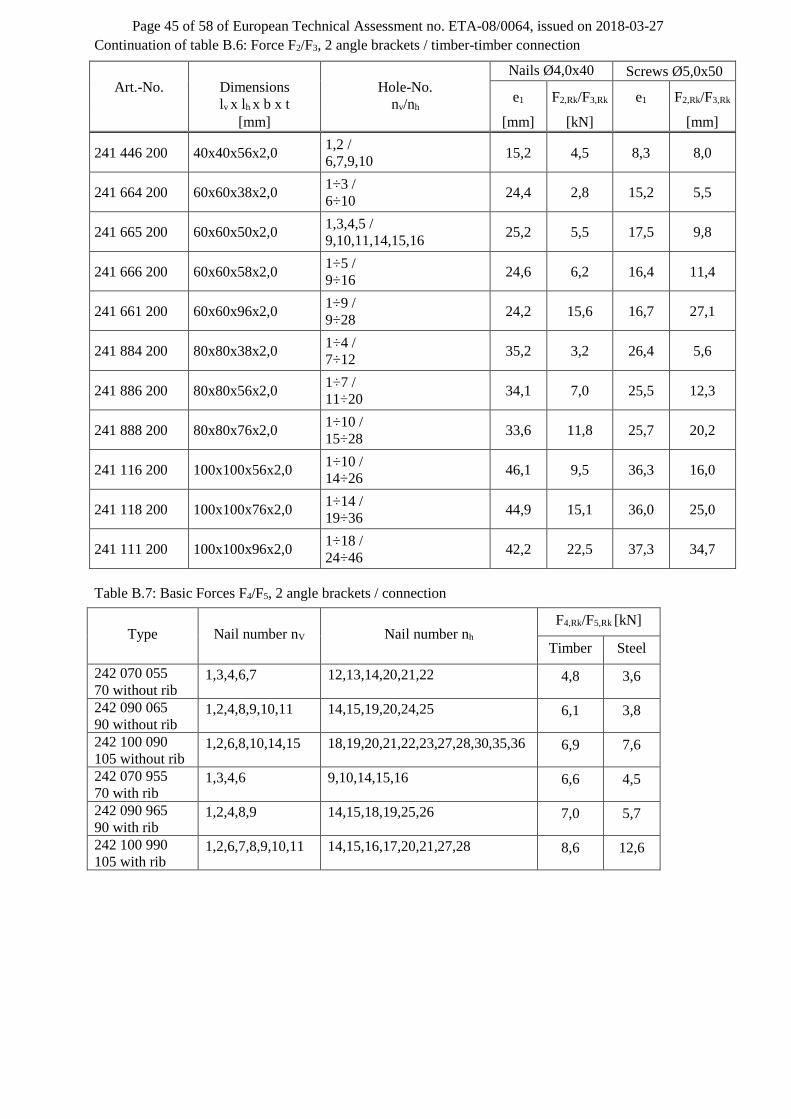
Page 45 of 58 of European Technical Assessment no. ETA-08/0064, issued on 2018-03-27
Continuation of table B.6: Force F2/F3, 2 angle brackets / timber-timber connection
Art.-No.
Dimensions
lv x lh x b x t
Hole-No.
nv/nh
Nails Ø4,0x40 Screws Ø5,0x50
e1 F2,Rk/F3,Rk e1 F2,Rk/F3,Rk
[mm] [mm] [kN] [mm]
241 446 200 40x40x56x2,0 1,2 /
6,7,9,10 15,2 4,5 8,3 8,0
241 664 200 60x60x38x2,0 1÷3 /
6÷10 24,4 2,8 15,2 5,5
241 665 200 60x60x50x2,0 1,3,4,5 /
9,10,11,14,15,16 25,2 5,5 17,5 9,8
241 666 200 60x60x58x2,0 1÷5 /
9÷16 24,6 6,2 16,4 11,4
241 661 200 60x60x96x2,0 1÷9 /
9÷28 24,2 15,6 16,7 27,1
241 884 200 80x80x38x2,0 1÷4 /
7÷12 35,2 3,2 26,4 5,6
241 886 200 80x80x56x2,0 1÷7 /
11÷20 34,1 7,0 25,5 12,3
241 888 200 80x80x76x2,0 1÷10 /
15÷28 33,6 11,8 25,7 20,2
241 116 200 100x100x56x2,0 1÷10 /
14÷26 46,1 9,5 36,3 16,0
241 118 200 100x100x76x2,0 1÷14 /
19÷36 44,9 15,1 36,0 25,0
241 111 200 100x100x96x2,0 1÷18 /
24÷46 42,2 22,5 37,3 34,7
Table B.7: Basic Forces F4/F5, 2 angle brackets / connection
Type Nail number nV Nail number nh F4,Rk/F5,Rk [kN]
Timber Steel
242 070 055
70 without rib 1,3,4,6,7 12,13,14,20,21,22 4,8 3,6
242 090 065
90 without rib 1,2,4,8,9,10,11 14,15,19,20,24,25 6,1 3,8
242 100 090
105 without rib 1,2,6,8,10,14,15 18,19,20,21,22,23,27,28,30,35,36 6,9 7,6
242 070 955
70 with rib 1,3,4,6 9,10,14,15,16 6,6 4,5
242 090 965
90 with rib 1,2,4,8,9 14,15,18,19,25,26 7,0 5,7
242 100 990
105 with rib 1,2,6,7,8,9,10,11 14,15,16,17,20,21,27,28 8,6 12,6

Page 46 of 58 of European Technical Assessment no. ETA-08/0064, issued on 2018-03-27
Table B.8: Basic Forces F4, 1 angle bracket / connection
Type Nail number nV Nail number nh Rk,4,5 [kN]
Timber Steel
242 070 955
70 with rib
1,3,4,6 9,10,14,15,16 8,0 3,6
242 090 965
90 with rib
1,2,4,8,9 14,15,18,19,25,26 9,2 4,4
242 100 990
105 with rib
1,2,6,7,8,9,10,11 14,15,16,17,20,21,27,28 12,5 7,4
Table B.9: Basic Forces F5, 1 angle bracket / connection
Type Nail number nV Nail number nh Rk,4,5 [kN]
Timber Steel
242 070 955
70 with rib 1,3,4,6 9,10,14,15,16 1,3 0,9
242 090 965
90 with rib 1,2,4,8,9 14,15,18,19,25,26 1,6 1,3
242 100 990
105 with rib 1,2,6,7,8,9,10,11 14,15,16,17,20,21,27,28 2,6 3,5

Page 47 of 58 of European Technical Assessment no. ETA-08/0064, issued on 2018-03-27
Characteristic load-carrying capacities – Purlin Ties
Table B.10: Characteristic load-carrying capacities Load F1 – 2 Purlin Ties / connection
Purlin Ties Number of
nails
Nail failure
FRk,N [kN]
Screw failure
FRk,N [kN]
Steel failure
FRk,S[kN]
Transverse
tensile failure
Type 171 ÷ 371
2x2 2,12 3,00 10,2
see EN 1995
2x3 3,36 4,75 10,2
2x4 5,33 7,54 10,2
2x5 8,37 11,8 10,2
2x6 9,71 13,7 10,2
2x7 13,7 19,3 10,2
2x8 15,1 21,3 10,2
2x9 19,4 27,5 10,2
2x10 21,1 29,8 10,2
2x11 25,6 36,2 10,2
2x12 27,5 38,9 10,2
2x13 32,1 45,4 10,2
2x14 34,2 48,3 10,2
2x15 38,8 54,8 10,2
2x16 41,0 58,0 10,2
Uni 170 ÷ 250
2 x 2 4,14 5,85 9,74
2 x 3 7,20 10,2 9,74
2 x 4 10,5 14,8 9,74
2 x 5 13,8 19,6 9,74
Characteristic load-carrying capacities – Hold-Downs
Table B.11: Characteristic load-carrying capacities Load F1 – 1 hold-down /connection;
timber-concrete/steel
type
capacity per
nail
Fv,Rk [kN] 1) 2)
capacity per
screw
Fv,Rk [kN] 1) 2)
concrete
steel 3) bolt
bending
Fm,Rk
[kN]
shear
Fv,Rk
[kN]
tensile
Ft,Rk
[kN]
kt
hold-down 200 ÷ 500
t = 2 mm 1,62 2,28
see
EN 1992
3,67 11,5 17,8 3,2
hold-down 200 ÷ 500
t = 4 mm 1,57 2,28 4,72 23,1 35,6 3,4
1) screws 5,0 x 50 mm according ETA-11/0024 2) The effective number of fasteners nef must be considered according EN 1995-1-1:2010, paragraph 8.3.1.1 (8) 3) base plate dimensions: 40 x 40 x 4,0 mm

Page 48 of 58 of European Technical Assessment no. ETA-08/0064, issued on 2018-03-27
Definitions of forces, their directions and eccentricity
Figure B.58: Forces - Beam to beam connection with angle brackets
Figure B.59: Forces – Column to concrete or steel connection with hold-downs (F1)
Figure B.60: Forces - Beam to beam connection with purlin ties (F1)
Component 1 Component 1
b
F5
F1
e
F1
F2 F3
F4 Component 2

Page 49 of 58 of European Technical Assessment no. ETA-08/0064, issued on 2018-03-27
Fastener specification
Angle Brackets: Holes are marked with numbers referring to the nailing pattern in Annex B.
Purlin Ties/Hold-Downs: The holes are to be nailed beginning at the end of the purlin tie/hold-down.
Support conditions
Purlin Ties: The distance between the timber elements in the area of the connection must not exceed
3 mm. The timber members are prevented from rotation.
Double angle brackets per connection
The angle brackets must be placed at each side opposite to each other, symmetrically to the component
axis.
Acting forces
F1 Lifting force acting along the central axis of the joint.
F2 and F3 Lateral force acting in the joint between the component 2 and component 1 in the
component 2 direction
F4 and F5 Lateral force acting in the component 1 direction along the central axis of the joint. If
the load is applied with an eccentricity e, a design for combined loading is required.
Single angle bracket per connection
Acting forces
F1 Lifting force acting in the central axis of the angle bracket. The component 2 shall be
prevented from rotation. If the component 2 is prevented from rotation the load-
carrying capacity will be half of a connection with double angle brackets.
F2 and F3 Lateral force acting in the joint between the component 2 and the component 1 in the
component 2 direction. The component 2 shall be prevented from rotation. If the
component 2 is prevented from rotation the load-carrying capacity will be half of a
connection with double angle brackets.
F4 and F5 Lateral force acting in the component 1 direction in the height of the top edge of
component 2. F4 is the lateral force towards the angle bracket; F5 is the lateral force
away from the angle bracket. Only the characteristic load-carrying capacities for angle
brackets with ribs are given.
Wane
Wane is not allowed, the timber has to be sharp-edged in the area of the angle brackets.
Timber splitting
For the lifting force F1 it must be checked in accordance with Eurocode 5 or a similar national Timber
Code that splitting will not occur.
Combined forces
If the forces F1 and F2/F3 or F4/F5 act at the same time, the following inequality shall be fulfilled:
2 2 2 2 2
1,d 2,d 3,d 4,d 5,d
Rd,1 Rd,2 Rd,3 Rd,4 Rd,5
F F F F F1
F F F F F
The forces F2 and F3 or F4 and F5 are forces with opposite direction. Therefore only one force F2 or F3,
respectively, and F4 or F5, respectively, is able to act simultaneously with F1, while the other shall be
set to zero.
If the load F4/F5 is applied with an eccentricity e, a design for combined loading for connections with
double angle brackets is required. Here, an additional force F1 has to be added to the existing force
F1.
1,d 4,d 5,d
eF F / F
B
B is the width of component 2.

Page 50 of 58 of European Technical Assessment no. ETA-08/0064, issued on 2018-03-27
Connection to concrete or steel with a bolt or metal anchor
The load FB,Ed for the design of a bolt or metal anchor is calculated as:
F k FtB,t,Ed Ed ·
where:
FB,t,Ed Bolt tensile load in N
kt Coefficient taking into account the moment arm (kt =1+e/z)
FEd Load on vertical flap of the hold-down in N
F F
F
Figure B.61: Forces - Beam to beam connection with purlin ties (F1)
Nail Patterns – Angle Bracket s in Load Cases F1, F2/F3, F4/F5
Angle Bracket 242070055 70x70x55
F1– column F1 – purlin, F2/F3, F4/F5
Nails in hole number: Nails in hole number:
1,2,3 / 1,3,4,6,7 /
12,13,14,20,21,22 12,13,14,20,21,22
Angle Bracket 242070955 70x70x55
F1– column F1 – purlin, F2/F3, F4/F5
Nails in hole number: Nails in hole number:
1,2,3 / 1,3,4,6 /
9,10,14,15,16 9,10,14,15,16

Page 51 of 58 of European Technical Assessment no. ETA-08/0064, issued on 2018-03-27
Angle Bracket 242090065 90x90x65
F1– column F1 – purlin, F2/F3, F4/F5
Nails in hole number: Nails in hole number:
1,2 / 1,2,4,8,9,10,11 /
14,15,19,20,24,25 14,15,19,20,24,25

Page 52 of 58 of European Technical Assessment no. ETA-08/0064, issued on 2018-03-27
Angle Bracket 242090965 90x90x65
F1– column F1 – purlin, F2/F3, F4/F5
Nails in hole number: Nails in hole number:
1,2 / 1,2,4,8,9 /
14,15,18,19,25,26 14,15,18,19,25,26
Angle Bracket 242 100 90 105x105x90
F1– column F1 – purlin, F2/F3, F4/F5
Nails in hole number: Nails in hole number:
1,2,6,7,8,9,10 / 1,2,6,8,10,14,15 /
18,19,20,21,22,23 18,19,20,21,22,23,
27,28,30,35,36 27,28,30,35,36
Angle Bracket 242 100 990 105x105x90
F1– column F1 – purlin, F2/F3, F4/F5
Nails in hole number: Nails in hole number:
1,2,6,7 / 1,2,6,7,8,9,10,11 /
14,15,16,17,20,21,27,28 14,15,16,17,20,21,27,28

Page 53 of 58 of European Technical Assessment no. ETA-08/0064, issued on 2018-03-27
Nail Patterns – Angle Brackets in Loadcase F2/F3
242 072 055 70x70x55
242 072 955 70x70x55
Nails in hole number:
1,3,4,6,7/
12,13,14,20,21,22
Nails in hole number:
1,3,4,6/
9,10,14,15,16
242 092 065 90x90x65 242 092 965 90x90x65
Nails in hole number:
1,2,4,8,9,10,11/
14,15,19,20,24,25
Nails in hole number:
1,2,4,8,9/
14,15,18,19,25,26
242 102 90 105x105x90 242 102 990 105x105x90
Nails in hole number:
1,2,6,8,10,14,15/
18,19,20,21,22,23,27
,28,30, 35,36
Nails in hole number:
1,2,6,7,8,9,10,11/
14,15,16,17,20,21,27,28
242 050 035 50x50x35 242 090 041 90x90x38

Page 54 of 58 of European Technical Assessment no. ETA-08/0064, issued on 2018-03-27
Nails in hole number:
1,2/
6,7,8,10
Nails in hole number:
1,2,6,7/
11,12,16,17,19,20
243 129 040 89x117x40 243 149 040 90x140x40
Nails in hole number:
1,2,4,5/
9,10,12,13,14,15,17,
18,20,21
Nails in hole number:
1,2,4,5/
9,10,12,13,14,15,17,
18,20,21,22,23
243 409 040 90x40x40 243 416 040 153x40x39
Nails in hole number:
1,2,4,5,6,7/
11,12,14,15
Nails in hole number:
1,2,3,4,6,7,8,9,10,
11,13,14/
15,16,18,19
243 608 040 80x60x40 243 609 060 84x60x56

Page 55 of 58 of European Technical Assessment no. ETA-08/0064, issued on 2018-03-27
Nails in hole number:
1÷5/
6÷10
Nails in hole number:
1,2,3,4,5,6,7,9/
10,11,12,14,15,16
243 609 062 84x60x56 243 905 054 90x50x55
Nails in hole number:
1,2,4,5,7/
9,10,11,12,13
Nails in hole number:
1,2,4,5,7,8,10,11/
14,15,19,20
243 915 965 90x149x63 243 948 048 90x48x48
Nails in hole number:
1,2,6,7/
12,13,14,15,19,20,21,
22,23,25,26,27
Nails in hole number:
1,2,4,5,6,7/
10,11,13,14
243 948 076 90x48x76 243 948 116 90x48x116

Page 56 of 58 of European Technical Assessment no. ETA-08/0064, issued on 2018-03-27
Nails in hole number:
1,2,3,6,7,8,9,10, 11,12/
16,17,20,21
Nails in hole number:
1,2,3,4,5,8,9,10,11,
12,13,15,16,17,18/
22,23,24,25,29,30,31
241 446 200 40x40x56 241 664 200 60x60x38
Nails in hole number:
1,2/
6,7,9,10
Nails in hole number:
1÷3/
6÷10
241 665 200 60x60x50 241 666 200 60x60x58
Nails in hole number:
1,3,4,5/
9,10,11,14,15,16
Nails in hole number:
1÷5/
9÷16
241 661 200 60x60x96 241 884 200 80x80x38
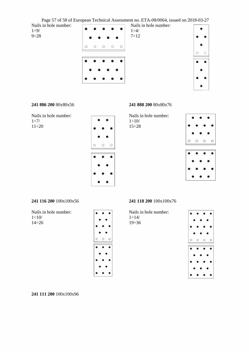
Page 57 of 58 of European Technical Assessment no. ETA-08/0064, issued on 2018-03-27
Nails in hole number:
1÷9/
9÷28
Nails in hole number:
1÷4/
7÷12
241 886 200 80x80x56 241 888 200 80x80x76
Nails in hole number:
1÷7/
11÷20
Nails in hole number:
1÷10/
15÷28
241 116 200 100x100x56
241 118 200 100x100x76
Nails in hole number:
1÷10/
14÷26
Nails in hole number:
1÷14/
19÷36
241 111 200 100x100x96

Page 58 of 58 of European Technical Assessment no. ETA-08/0064, issued on 2018-03-27
Nails in hole number:
1÷18/
24÷46


![En 422-04-651-0064[1]](https://static.fdocuments.in/doc/165x107/577d29831a28ab4e1ea6ff52/en-422-04-651-00641.jpg)