
European Project Semester 2010
124
European Project Semester 2010 Final Report “Nanotechnology for Energy Saving. Nano-Product (System)-Concept Design” Unit running the project: International Faculty of Engineering Project supervisor: prof. Zbigniew Kołaciński Group members: Sean McManus Katarzyna Przybyt Rosalía Ribela Rodríguez Juan Riera Bauzá Piotr Skusiewicz
Transcript of European Project Semester 2010

European Project Semester 2010
Final Report
“Nanotechnology for Energy Saving. Nano-Product (System)-Concept Design”
Unit running the project:
International Faculty of Engineering
Project supervisor:
prof. Zbigniew Kołaciński
Group members: Sean McManus
Katarzyna Przybyt
Rosalía Ribela Rodríguez
Juan Riera Bauzá
Piotr Skusiewicz
Nanotechnology for energy saving
We may be small but we think big! 1
CONTENTS
1. TEAM BUILDING PART .................................................................................................. 8
1.1. TEAM ..................................................................................................................................... 8
1.2. TEAM PROFILE ......................................................................................................................... 8
1.3. METHODS OF WORK ............................................................................................................... 10
1.4. PROJECT PROGRESS ................................................................................................................ 11
1.5. RECORD OF WORK ................................................................................................................. 13
2. OBJECTIVES OF THE PROJECT ....................................................................................... 14
2.1. STUDY ENERGY SAVING HOUSE BY APPLYING NANOTECHNOLOGY. ..................................................... 14
2.2. CONSTRUCT A CAPACITOR WITH THE USE OF BUCKY PAPER .............................................................. 15
3. ANALYSIS OF LOCATION AND SIZE OF A HOUSE ............................................................ 15
3.1. ANALYSIS OF LOCATION OF A HOUSE ........................................................................................... 15
3.2. ORIENTATION OF THE HOUSE .................................................................................................... 18
3.3. ANALYSIS OF SIZE OF THE HOUSE ................................................................................................ 19
4. NANOTECHNOLOGY ..................................................................................................... 20
4.1. CONCEPT .............................................................................................................................. 20
4.2. HOW SAFE IS NANOTECHNOLOGY? ............................................................................................. 21
4.3. APPLICATIONS ....................................................................................................................... 22
5. STUDY OF AN ENERGY SAVING HOUSE BY APPLYING NANOTECHNOLOGY IN 4 MAIN AREAS COMPARING IT WITH A MODERN HOUSE ................................................................... 23
5.1. GENERATION ......................................................................................................................... 24
5.1.1. Fuel Cells ..................................................................................................................... 24
5.1.1.1. The Market and Cost Analysis ............................................................................. 26
5.1.1.2. Energy Calculations .............................................................................................. 26
5.1.1.3. Nanotechnology within Fuel Cells ....................................................................... 27
5.1.1.4. Market Analysis ................................................................................................... 28
5.1.1.5. Conclusions .......................................................................................................... 29
5.1.2. Solar Cells ................................................................................................................... 29
5.1.2.1. Solar Cell Materials .............................................................................................. 32
5.1.2.2. Solar Panel Maintenance ..................................................................................... 34
5.1.2.3. Nano-solar cells ................................................................................................... 34

Nanotechnology for energy saving
We may be small but we think big! 2
5.1.2.4. Calculations for Nano Solar Panels ...................................................................... 35
5.1.2.5. Cost Estimation for Solar Panels on House ......................................................... 38
5.1.2.6. Future Nano Solar Technology ............................................................................ 38
5.1.2.7. Conclusions .......................................................................................................... 38
5.1.3. Wind Energy ............................................................................................................... 38
5.1.3.1. Study of wind turbines for a modern house........................................................ 40
5.1.3.2. Wind system has installed: .................................................................................. 41
5.1.3.3. Improvements with nanotechnology for wind turbines ..................................... 44
5.1.3.4. Market ................................................................................................................. 45
5.1.3.5. Carbon Nanotubes [3] [22] [23] [24] ................................................................... 46
5.2. CONVERSION ......................................................................................................................... 55
5.2.1. Illumination. ............................................................................................................... 55
5.2.1.1. Illumination of the house with LED. .................................................................... 57
5.2.1.2. How to improve LED illumination with nanotechnology. ................................... 58
5.2.1.3. Quantum dots ...................................................................................................... 59
5.2.1.4. Applications of quantum dots ............................................................................. 59
5.2.2. Appliances. ................................................................................................................. 63
5.2.2.1. High efficiency appliances. .................................................................................. 63
5.2.2.2. European Energy Labels. ..................................................................................... 64
5.2.2.3. Our appliances. .................................................................................................... 64
5.2.2.4. How to improve appliances with nanotechnology .............................................. 65
5.2.3. Biogas. ........................................................................................................................ 66
5.2.3.1. Biogas technology. ............................................................................................... 66
5.2.3.2. Biogas installation in a familiar house. ................................................................ 67
5.3. INSULATION .......................................................................................................................... 70
5.3.1. How can we improve that situation? ......................................................................... 72
5.3.1.1. Walls and doors. .................................................................................................. 72
5.3.1.2. Ventilation ........................................................................................................... 74
5.3.1.3. Windows .............................................................................................................. 74
5.3.2. Summary .................................................................................................................... 75
5.4. STORAGE .............................................................................................................................. 78

Nanotechnology for energy saving
We may be small but we think big! 3
5.4.1. Batteries ..................................................................................................................... 78
5.4.1.1. Conventional Batteries ........................................................................................ 79
5.4.1.2. Summary .............................................................................................................. 86
5.4.1.3. Possible improvement of batteries with application of nanotechnology .......... 88
5.4.2. Capacitors ................................................................................................................... 90
5.4.2.1. Possible improvement Capacitors with application of nanotechnology ............ 94
6. FEASIBILITY STUDY FOR A NANO ENERGY SAVING HOUSE ............................................ 95
6.1. GENERATION ......................................................................................................................... 95
6.1.1. Fuel cells: .................................................................................................................... 95
6.1.2. Solar cells .................................................................................................................... 96
6.1.3. Wind turbine .............................................................................................................. 96
6.2. CONVERSION ......................................................................................................................... 97
6.2.1. Feasibility study of LED illumination with nanotechnology ....................................... 97
6.2.2. Feasibility study of biogas installation ....................................................................... 98
6.2.3. Feasibility study of thermoelectricity ......................................................................... 98
6.3. INSULATION .......................................................................................................................... 98
6.4. STORAGE .............................................................................................................................. 99
6.4.1. Batteries and supercapacitors .................................................................................... 99
7. FUTURE APPLICATIONS .............................................................................................. 106
7.1.1. Saving water with nanotechnology .......................................................................... 106
8. BUCKY PAPER ............................................................................................................ 106
9. LABORATORY WORK REPORT .................................................................................... 107
10. CONCLUSIONS ........................................................................................................... 111
11. SOURCES ................................................................................................................... 113
12. PLAN OF THE HOUSE (A3 PAGE) ................................................................................. 116
13. ANNEXES ................................................................................................................... 117
13.1. ANNEX I EUROPEAN REGULATION FOR EFFICIENCY APPLIANCES ................................................... 117
13.2. ANNEX II PRINTED RESULTS OF THE LABORATORY EXPERIMENT. .................................................. 121
13.3. ANNEX IV MEETINGS AGENDA (DIGITAL VERSION) ................................................................... 123
13.4. ANNEX III DESIGN AND CALCULATIONS OF ILLUMINATION OF THE HOUSE (PDF FILES) ..................... 123
Nanotechnology for energy saving
We may be small but we think big! 4
INDEX OF ILLUSTRATIONS
Illustration 1 Location Dziwnów in the map .................................................................................. 15
Illustration 3 Dziwnów Picture taken from www.digitalphoto.pl/foto3/8885_b.jpg .................... 15
Illustration 2 Dziwnów Picture taken from www.skyscrapercity.com ........................................... 15
Illustration 4 Map of wind speed ................................................................................................... 16
Illustration 5 Map of solar radiation .............................................................................................. 17
Illustration 6 Map of average temperatures .................................................................................. 18
Illustration 7 Reaction on the electrodes ....................................................................................... 24
Illustration 8 Diagram fuel cells. Reactions on the electrodes ...................................................... 25
Illustration 9 Graph of the recent and expected trend of the value of the fuel cell industry ....... 26
Illustration 10 Nano fuel cell .......................................................................................................... 27
Illustration 11 Size of the nano fuel cell ......................................................................................... 28
Illustration 12 Single photovoltaic solar cell .................................................................................. 30
Illustration 13 Map of Europe and Africa showing the best areas for solar power ....................... 31
Illustration 14 Graph shows how current output changes with ambient temperature ................ 33
Illustration 15 Graph comparing most types of solar cell materials in terms of efficiency ........... 35
Illustration 16 Graph of peak solar energy per day in Poland ....................................................... 37
Illustration 17 Graph was used to work out the best inclination levels for maximum energy ..... 37
Illustration 19 Graph with the number of the wind turbines installed in 2020 ............................. 39
Illustration 18 Drawing of the rotor and blades of a wind turbine. ............................................... 39
Illustration 20 Wind system installed ............................................................................................. 41
Illustration 21 Mean wind speed at 80 m since year 2005 to year 2009 ....................................... 41
Illustration 22 Power of wind speed .............................................................................................. 42
Illustration 23 Comparison of the scale ......................................................................................... 43
Illustration 24 Schematic process since it is synthesized nanomaterial until applied to the turbine ........................................................................................................................................................ 44
Illustration 25 Graph World nanomaterials demand ..................................................................... 45
Illustration 26 Carbon structure ..................................................................................................... 47
Illustration 27 End of a SWNT ........................................................................................................ 47
Illustration 28 Bond lengths of carbon and atomic spacing of the hexagonal grid. ...................... 48
Illustration 29 A cord of nanotubes, made with about 100 of uniform diameter SWNT. ............. 48

Nanotechnology for energy saving
We may be small but we think big! 5
Illustration 30 Distribution of patents according to the energy fields........................................... 53
Illustration 31 LED diode symbolic representation. ........................................................................ 55
Illustration 32 Bulb ......................................................................................................................... 58
Illustration 33 Size of the quantum dots. ....................................................................................... 59
Illustration 34 Global market growth for quantum dots in promising commercial market sectors, 2008-2013 ($ Millions) ................................................................................................................... 60
Illustration 35 Phosphor dots shown under UV excitation. ........................................................... 61
Illustration 36 Quantum dots ......................................................................................................... 62
Illustration 37 Light creates a warm white light with LEDs that have Nanosys’ material layered over them ....................................................................................................................................... 63
Illustration 38 European Energy Labels .......................................................................................... 64
Illustration 39 Scheme of the process of the thermoelectricity .................................................... 65
Illustration 40 Primary production of biogas in Europe ................................................................. 67
Illustration 41 Scheme of the transportation of biogas to the kitchen ......................................... 68
Illustration 42 Nanomaterials for the construction of a digester .................................................. 69
Illustration 43 Digester installed .................................................................................................... 69
Illustration 44 Graph present percentage of energy wasted in a whole house ............................ 72
Illustration 45 Insulating material – fiber glass .............................................................................. 72
Illustration 46 Insulating material – styrofoam .............................................................................. 73
Illustration 47 Aerogels resistant to fire ........................................................................................ 73
Illustration 48 Ventilation – heat recovery system ........................................................................ 74
Illustration 49 Ventilation – counterflow heat recovery sytem ..................................................... 74
Illustration 50 Double glazing used in modern windows ............................................................... 75
Illustration 51 Graph energy saved due to nanotechnology ......................................................... 76
Illustration 52 – Yearly summary of energy consumption ............................................................. 77
Illustration 53 – detailed analysis of energy consumption ............................................................ 77
Illustration 54 – detailed analysis of energy gains ......................................................................... 77
Illustration 56 Sample drawing showing the voltaic cell from a battery. ..................................... 78
Illustration 57 Different types of NiCd batteries. ........................................................................... 79
Illustration 58 Car Lead acid battery used in a car. ........................................................................ 80
Illustration 59 Multi-cell nickel metal hydride battery. ................................................................. 81
Illustration 60 Picture of sample NiZn battery. .............................................................................. 83

Nanotechnology for energy saving
We may be small but we think big! 6
Illustration 61 Picture of a Multi-cell Lithium Ion battery. ............................................................ 84
Illustration 62 Lithium polymer battery from a Nokia cell phone. ................................................ 86
Illustration 63 Picture of single walled silicon nanotubes. ............................................................ 89
Illustration 64 Capacitor_schematic_with_dielectric.svg presenting the scheme of simple plate capacitor. ........................................................................................................................................ 90
Illustration 65 Picture of different types of electrolytic capacitors ............................................... 91
Illustration 66 Picture representing some of the Polyester Film Capacitors. ................................ 92
Illustration 67 Picture of ceramic capacitor ................................................................................... 93
Illustration 68 Picture showing different types of ultracapacitors ................................................ 93
Illustration 69 Picture showing how energy is stored in the double layer capacitor. ................... 94
Illustration 70 Picture presenting how the energy is stored between carbon nanotubes in supercapacitor. ............................................................................................................................... 94
Illustration 71 Insulation prices ...................................................................................................... 99
Illustration 72 A typical daily use of energy during 24 h period .................................................. 101
Illustration 73 Capacitor with bucky paper .................................................................................. 107
Illustration 74 Measuring stand ................................................................................................... 108
Illustration 75 Oscilloscope .......................................................................................................... 108
Illustration 76 Device for measuring capacitance ........................................................................ 109
Illustration 77 Energy stored in cspscitors ................................................................................... 110
Illustration 78 The capacitor on the left is a traditional electrolytic capacitor ........................... 110

Nanotechnology for energy saving
We may be small but we think big! 7
INDEX OF TABLES
Table 1 Distribution of the house ................................................................................................... 19
Table 2 Technical characteristics of the selected wind turbine ..................................................... 42
Table 3 Cost and energy generated with convencional wind turbine ........................................... 43
Table 4 Technical characteristics of one wind turbine with nanotubes ........................................ 46
Table 5 Table of comparative properties of a Single Wall Carbon Nanotubes (SWNT). ................ 50
Table 6 Examples of some applications ......................................................................................... 52
Table 7 Life of a LED ....................................................................................................................... 57
Table 8 Comparison of reliability ................................................................................................... 57
Table 9 Energy consumption study ................................................................................................ 76
Table 10 Different types of anodes and cathodes used in Li ion batteries. ................................... 85
Table 11 Comparison of popular battery types. .......................................................................... 87
Table 12 Performance comparison of conventional and nanotube capacitors with Li ion battery. ........................................................................................................................................................ 95
Table 13 Feasibility study of the wind turbine ............................................................................... 97
Table 14 Feasibility study of LED illumination................................................................................ 97
Table 15 Feasibility study of biogas installation ............................................................................ 98
Table 16 Appliances in a house, their average time of use per day and daily power consumption ...................................................................................................................................................... 100
Table 17 Lightning over the house, their daily use and power consumption.............................. 101
Table 18 Table presenting the calculations for traditional batteries. .......................................... 102
Table 19 Table presenting calculations for single ultracapacitors ............................................... 104
Table 20 Table presents calculations for the modules of capacitors ........................................... 105

Nanotechnology for energy saving
We may be small but we think big! 8
1. Team Building Part
1.1. Team
The name of our team, comes from our project description. Our team was
formed to study nanotechnology for energy saving. The conception for the name and logo came
up at an internal meeting during the forming stage of our project. It is grey green. Its colors
resemble technology (grey) and care about the environment by saving energy (green). We also
established the slogan:
“We may be small but we think big!”
It refers to our aim, and the aim of nanotechnology, to achieve impressive results in energy
saving with the use of very small things. Another aspect is that our team is small but we want to
plan excellent solutions for the future.
1.2. Team Profile
During a Team Building course we have made the Belbin test in order to estimate our
strengths and skills which could be best used during our project. This helped us to organize the
work. However we didn’t follow much the guidelines suggested in this test. We divided the roles
equally so that each of us was always occupied with work.
Now we would like to focus on each team member separately.
Sean McManus. Scotland
Sean is a 21 year old student from Scotland. He studies Chemical Engineering at Strathclyde
University. Thanks to him we had help in the chemistry of nanomaterials. In our team his
responsibilities were:
Look for fresh ideas
Do research on nanotechnology
Write final report (solar cells & Fuel cells)
Prepare of Midterm and Final Presentations
Help us with his native English skills

Nanotechnology for energy saving
We may be small but we think big! 9
Katarzyna Przybyt. Poland
Kasia is 22 year old student at Politechnika Łódzka. She studies Biotechnology. Thanks to this
project she could broaden her horizons. She knew little about nanotechnology however she
learned quickly and was helpful. In our team her responsibilities were:
Organize work within the team
Do research
Lead meetings
Prepare and putting together Team Building, Midterm and Final Presentations
To prepare graphic design of logo and presentation schemes
Write final report ( Batteries, Team Building Part)
Rosalía Ribela Rodríguez. Spain
Rosalía, 27, from Spain is a Chemical Engineering student at the Technical University of
Catalonia. Like Sean she helped us understand the chemistry of nanotechnology. At the
beginning her language skills constrained her but later she became a very active member. In our
team her responsibilities were:
Write the Meeting Agendas
Do research
Write and putting together the final report (Wind generators, House description)
Make midterm and final presentation
Help us in building the proper content of report
Juan Riera Bauzá. Spain
Joan is a 30 year old student who comes from Spain. He studies Electrical Engineering at the
Technical University of Catalonia. Thanks to his knowledge we had a lot of help in the field of
electricity and electronics. He was also very eager to both help and work within the team. In our
team his responsibilities were:
Secretarial duties
Find new ideas
Do research
Write and putting together a final report (Conversion, Lightning System, Biogas)
Make midterm and final presentation
Help us in understanding the electrical part of our project

Nanotechnology for energy saving
We may be small but we think big! 10
Piotr Skusiewicz. Poland
Piotrek, 22, comes from Poland. First, he studied Electrical Engineering but he changed it for
Mechanical Engineering. Thanks to his former studies he was very helpful in the electrical and
electronic part of the project. In our team his responsibilities were:
Provide fresh ideas
Do research
Write the final reort (insulation, buckypaper)
Prepare report from laboratories
Make midterm and final presentation
Overall, our team cooperated very well even if the Belbin test showed us that we might have
some problems with finishing the project and finding new ideas and information. We followed
the indicated rules and values, avoided conflicts and we always reached a consensus during
discussions. Our meetings were always productive (meeting Agendas from meetings with the
supervisor and Internal ones can be found in Appendix) and helped us to organize work and
move forward.
1.3. Methods of work
During our Team Building classes we established ground rules and values that will help us in
the course of project.
TASKS
Set small and big goals.
Make decisions with discussions and compromising.
Solve problems discussion.
Evaluate the project regularly prizing, success but not necessary.
Manage meetings with the supervisor, with ourselves. The meetings are obligatory on
Wednesday.
Determine roles and responsibilities. roles are not necessary.
Give and receive info presentation (inside the group).
Recognize and awarding accomplishments is not necessary.
INTERPERSONAL RELATIONSHIPS
Encourage everyone’s participation by helping, good relationships.
Better understanding group dynamic by discussion and evaluation of tasks and keeping
good relationships.

Nanotechnology for energy saving
We may be small but we think big! 11
Give and solicit constructive feedback will be made by discussion, during meetings.
Managing conflict by solving problems during discussion (problems, feelings) and
compromising.
Dealing with gossip by speaking out loud, discussing, speaking clearly and honestly, solve
problems.
Improve listening by helping each other, be patient.
Acknowledge and respect individual differences by keeping rules of good relationships.
Respecting each other.
Present ourselves to others outside the team.
Build trust by following the rules. Solving problems and understanding that we are a
TEAM not INDIVIDUALS.
THE RULES OF THE TEAM
We set small and big goals by discussion, our biggest success will be accomplishing them
on time.
At our regular meetings we:
- evaluated process
- solved problems
- shared knowledge
- shared responsibilities
To have a good team, all members participate, are honest, ask and answer questions,
give and receive constructive feedback.
We have to remember that to build trust we need to follow the rules and understand
that we are a TEAM not single beings.
1.4. Project Progress
At the beginning we divided our project into 15 weeks and designed a rough system of work
that was later upgraded.
STAG
E
Introduction
& Storming Norming Performing Finishing
WEE
K 1 2 3 4 5 6 7 8 9 10 11 12 13 14 15

Nanotechnology for energy saving
We may be small but we think big! 12
In first three weeks we established fundamental rules for our team and performed team
building exercises in order to help our team integrate. In the Norming stage we held a major
presentation on Team Building. The Performing Stage began with a Midterm presentation that
showed our progress on building the team, we also presented our objectives for this project
(Designing and feasibility study of a house powered by nanotechnology, and building and testing
a nanocapacitor). At this stage we had a lot of internal presentations that helped us understand
new ideas and gather information. In 13th week of the project we gathered all the information
and ideas and formulated the content of report. Then we shared the responsibilities and started
writing the report. When we were at the end of writing the final report we started working on
the final presentation, which will be held in 15th week of our project.
To organize our work system we designed the action plan shown in the picture below.
START
Problem analysis
Group Stabilization
Research Internal evaluation
Finding purpose
Midterm evalu ation
Research Internal evaluation
Final Evaluation
END

Nanotechnology for energy saving
We may be small but we think big! 13
Our project began with group stabilization and problem analysis, then we started looking for
information regarding our project. We had done internal evaluation to discuss the ideas and
decide on further research. After this loophole we found the purpose and objectives of the
project that were presented at the midterm evaluation. After this, in the performing stage we
again looked for ideas and information and made an internal evaluation to see our progress.
Thanks to this we gathered enough information to start writing the final report and making the
final presentation, which will be presented at final evaluation, and after the approval of our
work we will finish our project.
1.5. Record of Work
It was assumed during this one semester project that we will spend around 90 class hours on
learning. We did not spend this amount on time only at IFE and in meetings with the supervisor.
Additionally, we spent even more hours on doing research, finding new ideas and developing
knowledge both on our own and together.
In the course of the project we held 15 meetings with the supervisor, which amounts to one
meeting per weekend, however it was not like that. The exact schedule of meetings can be
found in the calendars in the appendix. We also held 12 internal meetings that supplemented
meetings with the supervisor and helped us to organize our work. The schedule as well as
agendas (both internal meetings and meetings with the supervisor) can be found in the
appendix.
As mentioned, our project took us more than 90 hours but we did not take the record of time
spent on work. We can represent our workload by an inverted pyramid that can be seen below.
Finishing
Performing
Norming
Forming & Storming
Gro
win
g am
ou
nt
of
tim
e sp
ent
on
th
e p
roje
ct

Nanotechnology for energy saving
We may be small but we think big! 14
One can see that the amount of time we spent on the project was constantly growing. During
the Forming and Storming stage we did little work, only team building exercises, as well as were
introduced to our project by the supervisor. In the norming stage, apart from team building
exercises, we started looking for information about nanotechnology, we had one major internal
evaluation and we found the objectives. The time input slightly increased. Then we entered the
Performing stage and started hard work on the project. The last stage, Finishing, lasted for only
2 weeks but the amount of work was really large, we had to gather all the information and
ideas, write the final report and make the final presentation.
In order to help organize work we used an internet based working platform called Achievo.
Then, because of its very slow operation we changed for Google products (Gmail, Google
Calendar, Google Docs) where we gathered all our documents and schedules as well as To Do
lists. In the appendix one can see printouts from Google Calendar. We found it very helpful
because all of our information and ideas are stored in one easily-accessible place.
2. Objectives of the Project
This project aims to investigate possible energy savings that nanotechnology can bring to a
conventional house and build and test a capacitor constructed with bucky paper in the
laboratory.
2.1. Study energy saving house by applying nanotechnology.
To accomplish the first objective, we will focus on four main areas:
Generation: How to improve solar panels, fuel cells and wind turbines. These
devices allow us to generate energy through natural sources, like the sun and wind and
reduce the use of energy sources, traditional finite and polluting, such as crude oil.
Conversion: How to improve lighting and appliances to avoid a significant loss of
energy when converting electricity into light or running appliances. Also to use the
organic matter and convert waste into biogas.
Insulation: How to increase the isolation of a house using nanomaterials to help
keep the house warm in winter and cool in summer, therefore saving on heating and air
conditioning expenses.
Storage: How to improve batteries and capacitors to increase energy storage
capacity so that it can be accessed when needed.

Nanotechnology for energy saving
We may be small but we think big! 15
2.2. Construct a Capacitor with the use of bucky paper
To complete the second goal, in the laboratory we will build a bucky paper capacitor and also
compare it with standard and super capacitors.
3. Analysis of location and size of a house
3.1. Analysis of location of a house
The house is located in Dziwnow, Poland.
Illustration 1 Location Dziwnów in the map
Picture taken from http://en.wikipedia.org/wiki/Dziwn%C3%B3w
Dziwnow is a town in north-western Poland situated on the Baltic Sea at the mouth of the river
Dziwna.
POLAND
Illustration 2 Dziwnów Picture taken from www.digitalphoto.pl/foto3/8885_b.jpg
Illustration 3 Dziwnów Picture taken from www.skyscrapercity.com
Nanotechnology for energy saving
We may be small but we think big! 16
It is interesting to develop our project by locating a house in Poland, which is the country
where we are.
To choose the place where we have located the house in Poland, we have analyzed the annual
average wind speed, the impact of solar radiation and the mean annual temperatures in the
country.
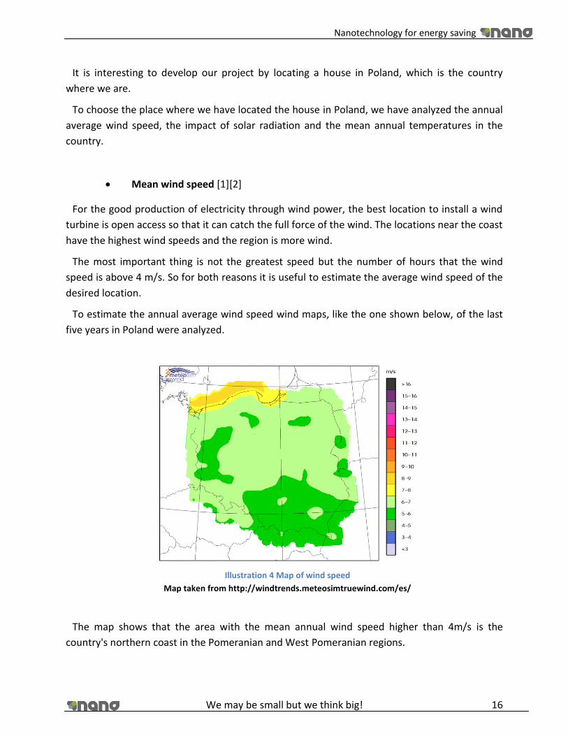
Mean wind speed [1][2]
For the good production of electricity through wind power, the best location to install a wind
turbine is open access so that it can catch the full force of the wind. The locations near the coast
have the highest wind speeds and the region is more wind.
The most important thing is not the greatest speed but the number of hours that the wind
speed is above 4 m/s. So for both reasons it is useful to estimate the average wind speed of the
desired location.
To estimate the annual average wind speed wind maps, like the one shown below, of the last
five years in Poland were analyzed.
Illustration 4 Map of wind speed
Map taken from http://windtrends.meteosimtruewind.com/es/
The map shows that the area with the mean annual wind speed higher than 4m/s is the
country's northern coast in the Pomeranian and West Pomeranian regions.

Nanotechnology for energy saving
We may be small but we think big! 17
Solar radiation
To determinie whether the location is also convenient for installing photovoltaic solar panels
to produce electricity from light, we analyzed solar radiation maps and the presence of shadows
coming from high buildings or plants.
Illustration 5 Map of solar radiation
Map taken from www.wikipedia.com
As shown in the map the areas with higher solar radiation are in the south in Karpaty and the
north coast of the Pomeranian and West Pomeranian regions, the latter coinciding with the area
with a good mean wind speed per year.
Mean temperatures
As in the two previous cases here the map of average annual temperature in Poland is
analysed.
The areas with the highest average temperatures correspond to the country's west
(Westpomeranian, Lubuskie, Lower Silesia and Opole regions) while the colder temperatures to
the south of the country, in Karpaty.

Nanotechnology for energy saving
We may be small but we think big! 18
Illustration 6 Map of average temperatures
Map taken from www.wikipedia.com
Analyzing the three previous studies, there are two possible locations, one in the south with,
good solar radiation and the other in the west, due to a good average wind speed and average
annual temperatures.
Pooling the data shows that the best area to locate the house is in the northwest, because the
south has cold temperatures and the average wind speed does not reach values high enough to
produce energy with windmills.
For these reasons, we place the house in Dziwnow, an excellent location for a modern house in
which to implement renewable energy and other technologies, such as isolation, that save
electricity and increase the savings with the implementation of nanotechnology.
3.2. Orientation of the house
The facade of the house will look to the South, since more surface area is exposed to the sun.
A well located house allows sunlight to penetrate laterally in the winter to reduce heating bills
and prevent the direct entry of sunshine in the summer to reduce air conditioning bills.
Nanotechnology for energy saving
We may be small but we think big! 19
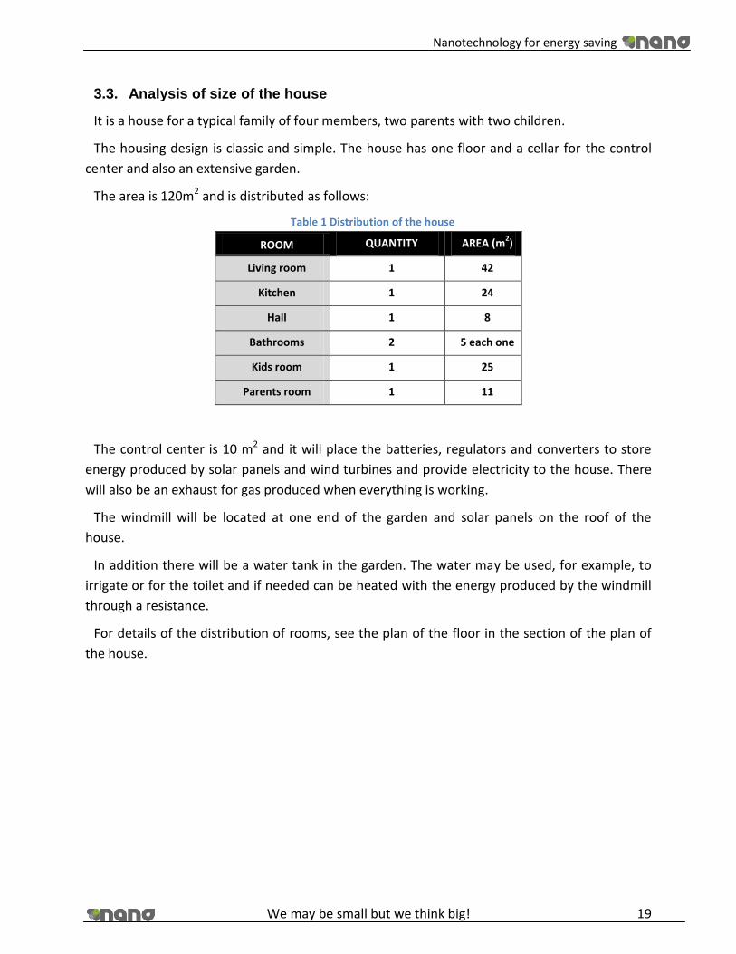
3.3. Analysis of size of the house
It is a house for a typical family of four members, two parents with two children.
The housing design is classic and simple. The house has one floor and a cellar for the control
center and also an extensive garden.
The area is 120m2 and is distributed as follows:
Table 1 Distribution of the house
ROOM QUANTITY AREA (m2)
Living room 1 42
Kitchen 1 24
Hall 1 8
Bathrooms 2 5 each one
Kids room 1 25
Parents room 1 11
The control center is 10 m2 and it will place the batteries, regulators and converters to store
energy produced by solar panels and wind turbines and provide electricity to the house. There
will also be an exhaust for gas produced when everything is working.
The windmill will be located at one end of the garden and solar panels on the roof of the
house.
In addition there will be a water tank in the garden. The water may be used, for example, to
irrigate or for the toilet and if needed can be heated with the energy produced by the windmill
through a resistance.
For details of the distribution of rooms, see the plan of the floor in the section of the plan of
the house.

Nanotechnology for energy saving
We may be small but we think big! 20
4. Nanotechnology
Nanotechnology is a new science which is based on the discovery of fullerenes, manometric
scale particles formed by carbon atoms, to innovative machines that can be implanted into our
bodies without any difficulty.
4.1. Concept
Nanotechnology is the study, design, creation, synthesis, manipulation and application of
materials, devices and functional systems through the control of matter at the nanoscale, and
the exploitation of phenomena and properties of matter at the nanoscale.
When handling the matter on such a minuscule scale of atoms and molecules, entirely new
phenomena and properties are revealed. Therefore, scientists use nanotechnology to create
materials, devices and innovative and inexpensive systems with unique properties.
The interest of the nano is mostly in the properties of the materials at these scales and how
they differ from macro dimensions.
Nanotechnology has three key objectives, which are:
1. Place each atom in the right place.
2. Make almost any structure consistent with the laws of physics and chemistry that we can
specify and describe at the atomic level.
3. Make sure manufacturing costs do not exceed considerably, the cost of raw materials and
energy used in the process.
The technology is still at a very early stage, but every day truly amazing steps that could lead
to a qualitative leap in practical applications, are happening with some incipient nanoparticles
or with nanotubes.
Because Nanotechnology is at an early stage of development, there is little demand and prices
for the customer are still very high. It is expected that in 5-10 years the demand for these
products will increase and prices will drop in order to offer customers a quality product at
competitive and affordable prices. [3]

Nanotechnology for energy saving
We may be small but we think big! 21
4.2. How safe is nanotechnology?
As with all new products, no records are available regarding side effects, so it is very important
to control quality and safety.
The United Nations reports, the Royal Society of British or EU admit that their understanding
of these effects is still scarce.
The conclusions of a conference on nanosafety organized in Helsinki in October 2006 by the
Commission were as such: "Nanomaterials are small compared with the body's natural barriers
to foreign objects. They can have novel properties compared with those of the same substance
in macro form. Scientists are still unable to predict these new properties. We must accelerate
the characterization [of NanoMed-terials] and search for safe design to prevent unknown risks
hamper the development of nanotechnology. "
It is known that nanoparticles, once in the body, after being inhaled, ingested, injected or
absorbed through the skin, can cross the blood-brain barrier that prevents potentially toxic
substances in the bloodstream enter the brain. [4]
An interview with Dr. Uwe Vohrer, an expert in CNT characterization and safety research at the
Fraunhofer Institute for Interfacial Engineering and Biotechnology (IGB) in Stuttgart:
“How safe are CNTs?
Can carbon nanotubes be harmful to health?
Unfortunately there is no universal answer to that question, because not all nanotubes are the
same. Manufactured products simply differ too greatly, for example in terms of the length and
diameter of the tubes, or the catalysts used in production. For Baytubes®, however, current
research shows that a risk to man and the environment from CNT agglomerates can be ruled
out almost entirely. A toxicologist would never say the risk is zero, because even table salt can
be toxic if you swallow large amounts of it.
How safe are products containing nanotubes?
Nanotubes are very firmly bound in plastic composites. We have not found any free nanotube
particles at all from such products.” [5]
Nanoecotoxicología and nanotoxicology are responsible for investigating the side effects of
this new science; nanotechnology will become increasingly present in our everyday life. But
both nanoecotoxicología and nanotoxicology sciences are also new so we do not know what
influence possible effects will have.

Nanotechnology for energy saving
We may be small but we think big! 22
There have been some studies on how nanoparticles affect our health and according to the
expert who conducted the study the majority of nanoparticles are likely to be harmless, but you
have to consider "case by case." Do not rule out "acute adverse effects and long-term
consequences," and stresses that a material is safe to normal size so does not mean that your
nano version is safe.
Surely we need a more systematic research, and public control policies specific to the industry.
"United States and Europe spend 7,700 million euros to investigate potential benefits of
nanotechnology, but only 30 million euros to assess their risks. [4]
4.3. Applications
Manipulating matter at the scale of atoms and molecules get multiple properties, that’s why
nanotechnology has many various applications.
The most important applications that will provide a breakthrough in human life are: medicine,
the energy sector, electronics and materials, but other sectors, also being studied such as food
or cosmetics.
Examples of specific applications of nanotechnology in various sectors: [6]
Medicine
Researchers have synthesized "nanoparticles” capable of being incorporated into drugs where
they are needed or new materials able to communicate with cells and induce tissue
regeneration.
Food
Nanotechnology applications in food will improve the chances of detecting small amounts of
harmful substances, to create optical sensors for industrial fryers online for gaining control of
production.
Electronics
Advances in nanotechnology mean that computers will stop using the system to integrate
silicon as the transistors that compose it and begin to cope with what is called quantum
mechanics, which will make use of atomic-scale transistor possible.
Nano-cables are capable of detecting gases
Researchers at Cornell University have achieved a technological breakthrough with the
discovery of a simple way of placing nanowires on an electrode, and have built a prototype high-

Nanotechnology for energy saving
We may be small but we think big! 23
speed detector capable for detecting chemicals in nano quantities for example ammonia gas -
the device can detect these gases at an extremely low concentration - 500 parts per trillion.
Currently, the Cornell team of scientists are investigating the development of detectors for
other types of gases and hope to create a detector with a variety of cables sensitive to various
chemical materials. A device with this capability could quickly detect and analyze the
composition of gases in the atmosphere, the researchers said.
The advantage of this method is that it accomplished, with relative ease, the integration of
nanowires with conventional electronics. According to the researchers, devices made from
nanowire detectors could be available within three or four years. [7]
Intelligent textiles
Since technological advances allow to implement electronic microchips into tissues in order to
develop fabrics capable of changing color, sending and receiving radio waves, or act as a
keyboard.
There are many who believe that the integration of technology with the tissues has enormous
potential and now clothes, curtains, chairs, blinds, wall paper are slowly starting to emerge on
the market. For example, a pioneer of this technique, Maggie Orth, founder, president and sole
employee of International Fashion Machines, has just created a fabric that changes color. The
fabrics containing fibers with moving electronic controls change its color when heated. He has
also invented a "musical jacket, a garment that has an electronic musical keyboard that can be
played by pressing a hand on the embroidery, and an evening dress with lights that shine.
According to Orth, one day our clothes may not only change according to the external
temperature but could also contain a whole complex system of communication that allows
people to call others as we do now with a phone. [8]
Among all the applications that has nanotechnology, our project will focus on the
implementation in the energy sector.
5. Study of an energy saving house by applying nanotechnology in
4 main areas comparing it with a modern house
In the course of our project we decided to design a house that will use nanotechnology for
energy saving. We will focus on 4 main areas where nanotechnology can be implemented: these
are generation, conversion, insulation and storage.

Nanotechnology for energy saving
We may be small but we think big! 24
5.1. Generation
5.1.1. Fuel Cells
A fuel cell is a device based on a very simple of science. Essentially, a fuel cell brings hydrogen
and oxygen together (usually in the presence of a catalyst) in order to produce electricity. A fuel
cell generally consists of two porous electrodes (anode and cathode) with an electrolyte
between the two. A fuel is passed onto the anode and the cathode receives an oxidant; in most
cases, these substances are hydrogen and oxygen respectively. The electrolyte separates the
two substances so as there is no physical contact. The fuel is oxidized (and electrons released) at
the anode; at the cathode the oxidant is reduced (and electrons absorbed). It will also be
possible to use methanol as the fuel for the appliance but is proposed to be a future application
which could be used to power small electronic devices such as mobile phones and mp3 players,
so this report will focus on the hydrogen fuel cell technology.
The anode and the cathode must be connected by an electrical conductor for the process to
work correctly. The charge transfer of the fuel cell is affected by the flow of ions through the
electrolyte, this is very useful for the engineers using the device since the overall energy
production rate can be controlled and worked out using the mass flow rate of the reactants.
On the next page there is a picture which clearly shows how the fuel cell functions:
Illustration 7 Reaction on the electrodes
Picture taken from http://www.fuelcells.org/info/library/fchandbook.pdf

Nanotechnology for energy saving
We may be small but we think big! 25
Here is another diagram which clearly shows the flow of electrons at the fuel cell electrodes:
Illustration 8 Diagram fuel cells. Reactions on the electrodes
Picture taken from http://www.fuelcells.org/info/library/fchandbook.pdf
The electrodes of the fuel cell are not converted, which means they cannot be discharged the
way as capacitor or a battery can. The reaction is essentially a combustion reaction, but it is
termed cold combustion as the reaction is controlled and has a catalyst present. The working
temperature of the electrolyte is around 40-80 degrees Celsius.
Here are the reactions that occur on the electrodes; the overall energy of the reaction is
shown as well:
Anode: (oxidation)
Cathode: (reduction)
Overall reaction: ΔG = -237.3 kJ/mol
At the anode, hydrogen molecules are oxidized to positively charged hydrogen ions (protons),
releasing electrons. The protons can be conducted through the polymer membrane to the
cathode. If the anode and cathode are connected by any electric conductor, electrons and
hydrogen ions flow to the cathode and react there with oxygen, forming water. The electrons
can perform work in the process. [9]

Nanotechnology for energy saving
We may be small but we think big! 26
5.1.1.1. The Market and Cost Analysis
Fuel cells are quickly becoming highly sought after appliances. As we move away from fossil
fuels, more and more companies are reaching out to hydrogen technology as a new way to
produce energy.
Here is a graph of the recent and expected trend of the value of the fuel cell industry:
Illustration 9 Graph of the recent and expected trend of the value of the fuel cell industry
Map taken from BCC Research
5.1.1.2. Energy Calculations
First, we must calculate the flow rate of hydrogen needed to enter the fuel cell so that we
receive the desired amount of current at the output end. [9]
So we first work out the flow rate needed to produce one Amp of current.
For every molecule of hydrogen (H2) that reacts within a fuel cell, two electrons are liberated
at the fuel cell anode. This is most easily seen in the PAFC and PEFC because of the simplicity of
the anode (fuel) reaction, although the rule of two electrons per diatomic hydrogen molecule
(H2) holds true for all fuel cell types. The solution also requires knowledge of the definition of an
Ampere (A) and an equivalence of electrons
Here is the reaction that is taking place at the anode: H2 >>> 2H+ + 2e-
This is equal to 0.037605g per Amp of electricity produced.
Thus for a 1.5A circuit which is the same as the one is our house we need 0.037604 x 1.5 =
0.056406 g per hour. [10]
For our conventional energy saving house we will use a Reformed Methanol Fuel Cell because
it works within our power range (5W – 100kW). It is for commercial use as well as research and
it has a relatively high efficiency (25 – 40%) it is not one of the most expensive fuel cells to buy.
This is a type of proton exchange fuel cell and it has some advantages over the similar “Direct
Methanol Fuel Cell”, these being it is more efficient, smaller cell stacks, no water management

Nanotechnology for energy saving
We may be small but we think big! 27
and operation at lower temperature. These types of fuel cells produce carbon dioxide and water
as waste products.
Methanol might be a good substance to use as a fuel as it is naturally occurring, biodegradable
and a good hydrogen carrier.
These fuel cells cost $5000 for a 25W cell, so in our house it makes sense that we use them to
power appliances such as the fridge, TV and laptop. If we buy 4 of these that gives us a total cost
of $20,000. [11]
5.1.1.3. Nanotechnology within Fuel Cells
The future of fuel cells lies within the realm of nanotechnology. A professor at a university is
Pittsburgh, USA said ”For laptops, cell phones and other portable electronics"we envision a fuel
cell system about the size of a cigarette lighter that could be re-fuelled by inserting a small
cartridge of methanol,". It is also expected that nano-fuel cells will come into use in the
automobile industry, with tanks of methanol being used to power the whole car.
The difference with nano fuel cells as compared to regular ones is that the catalyst substance
is made to the nanoscale (width of 3nm and a length of 10nm). The catalysts properties then
increase greatly. For instance, because of the huge rise in surface area, there are lots more
active sites available for methanol to react and break down. This means the fuel cells are far
more efficient and less methanol has to be used to produce the same amount of power
compared to conventional fuel cells.
The improvement goes further when we think about constructing the electrodes using carbon
nanotubes. The nanotubes have a much better rate of electrical conduction than the original
metal electrodes. This in turn increases the efficiency of the fuel cell as not so much hydrogen is
needed to create the electrical current needed.
Illustration 10 Nano fuel cell
Picture taken from www.wikipedia.org
Nanotechnology for energy saving
We may be small but we think big! 28
With the use of carbon nanotubes for the electrodes and a nanoscale catalyst, the
performance rises by a factor of 3 with one fourth the catalyst loadings compared with previous
generations. This, alongside the optimization of the fuel, air and water mixtures 15lb of units
can deliver 600 to 1200 W of power per day.
The US military has been given fuel cell prototypes which have been safety and productivity
tested up to military standard with resistance to rain, wind and sand. The large Californian
corporation UltraCell opened a massive fuel cell manufacturing plant worth $74 million in 2007
and expects to begin production of commercial nano fuel cells by the end of this year. They also
gave prototypes to the US army for testing. [12]
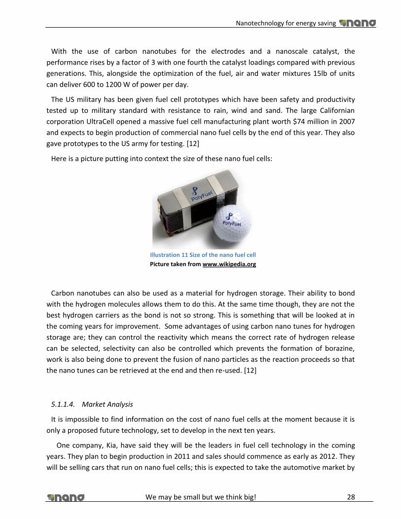
Here is a picture putting into context the size of these nano fuel cells:
Illustration 11 Size of the nano fuel cell
Picture taken from www.wikipedia.org
Carbon nanotubes can also be used as a material for hydrogen storage. Their ability to bond
with the hydrogen molecules allows them to do this. At the same time though, they are not the
best hydrogen carriers as the bond is not so strong. This is something that will be looked at in
the coming years for improvement. Some advantages of using carbon nano tunes for hydrogen
storage are; they can control the reactivity which means the correct rate of hydrogen release
can be selected, selectivity can also be controlled which prevents the formation of borazine,
work is also being done to prevent the fusion of nano particles as the reaction proceeds so that
the nano tunes can be retrieved at the end and then re-used. [12]
5.1.1.4. Market Analysis
It is impossible to find information on the cost of nano fuel cells at the moment because it is
only a proposed future technology, set to develop in the next ten years.
One company, Kia, have said they will be the leaders in fuel cell technology in the coming
years. They plan to begin production in 2011 and sales should commence as early as 2012. They
will be selling cars that run on nano fuel cells; this is expected to take the automotive market by

Nanotechnology for energy saving
We may be small but we think big! 29
storm. They are expecting to sell around 1000 or 2000 vehicles per year for the first 2 years of
production, and then they are confident that the technology will catch on quickly so sales will
rise to 20,000 after 4 or 5 years on the market. They have been working on these fuel cell
products since the year 2000 along with rival company Hyundai. They will initially offer their
product to government bodies and researchers to try and spread the cars credibility. The
company’s Borrego FCEV prototype reaches 100 km/h in 12 seconds and has a top speed of 170
km/h. The SUV is capable of covering 600 km before needing to refuel. The electrical energy is
delivered to the car’s engine via a super capacitor, which allows a much quicker response time
then with a battery like other models use. [13]
5.1.1.5. Conclusions
In conclusion, it has been found from detailed study into the area of fuel cells that we can
power household appliances such as the T.V and computer through use of solar cells. The total
cost is $20,000 for our conventional energy saving house.
Prices and models of nano solar cells were unable to be found because it is such a new
technology. It can be expected that nano fuel cell products will be seen in the next 5 years,
these will be cars and devices used to power laptops , phones and other such electrical
appliances.
A lot of time and money is being spent world-wide on research into the nano fuel cell market
especially in USA and in large automotive countries. In the not so distant future we can expect
to see a range of small electrical appliances such as lap tops and cell phones powered
completely with nano fuel cells. Nano fuel cell technology may boost the energy sector closer to
where it should be in the next few years as we move further away from non-renewable fossil
fuels.
5.1.2. Solar Cells
The photovololtaic cell (solar cell) is a device that uses the difference in materials to create an
electric current when the surface of a certain material is exposed to photons of light of a specific
energy. The flow of electricity occurs due to the materials being doped; this is the process
whereby the conductor has another chemical added to it to create holes within the metallic
bonding structure. The material is now called a semi conductor. When incident light strikes the
surface of the material, the energy excites one electron (or more depending on the material)
making it move, the only place it can go is into the nearest hole. This process repeats itself until

Nanotechnology for energy saving
We may be small but we think big! 30
there is a constant flow of electricity. In most cases, the electricity flows to a storage facility
such as a battery or a capacitor so it can be used at a later time.
Photovoltaic is the field of technology and research related to the devices which directly
convert sunlight into electricity.
Due to the growing demand for renewable energy sources, the manufacture of solar cells and
photovoltaic arrays has advanced rapidly in recent years.
Photovoltaic production has been doubling every 2 years, increasing by an average of 48
percent each year since 2002, making it the world’s fastest-growing energy technology.
The solar cell is the elementary building block of the photovoltaic technology. Solar cells are
made of semiconductor materials, such as silicon. One of the properties of semiconductors that
makes them most useful is that their conductivity may easily be modified by introducing
impurities into their crystal lattice.
There are several types of solar cells. However, more than 90% of the solar cells currently
made worldwide consist of wafer-based silicon cells. They are either cut from a single crystal rod
or from a block composed of many crystals and are correspondingly called mono-crystalline or
multi-crystalline silicon solar cells. [10]
A number of solar cells electrically connected to each other and mounted in a single support
structure or frame is called a ‘photovoltaic module’. Modules are designed to supply electricity
at a certain voltage, such as a common 12 volt system which works with 36 solar cells. The
current produced is directly dependent on the intensity of light reaching the module.
Several modules can be wired together to form an array. Photovoltaic modules and arrays
produce direct-current electricity. They can be connected in both series and parallel electrical
arrangements to produce any required voltage and current combination.
The picture below shows a single photovoltaic solar cell:
Illustration 12 Single photovoltaic solar cell
Picture taken from http://www.goldbulletin.org/
Nanotechnology for energy saving
We may be small but we think big! 31
Solar power is a very attractive form of renewable energy as it is free to harness, completely
harm free to the environment. It is a fairly developed technology as it has been around for
around 50 years but it was never heavily invested in due to the abundance of fossil fuels and
peoples lack of thought about the future. Now and in the next 5 or ten years though, solar
power is expected to play a massive part in the reshaping of our energy production methods as
almost every government in the world has set hard targets in terms of renewable energy used
as a percentage of total energy.
One of the main problems with solar power is that not everywhere in the world is the
abundance of light energy from the sun needed to convert a sufficient amount of energy. For
example, 20 German firms have come together and are about to embark on a $400 billion
project to gather solar energy from the sun in the deserts of north Africa and send it to Europe.
Although the major technology is not solar cells (they will use an array of mirrors to reflect
sunlight to a river and use the heat energy to power a turbine) the scope of this project shows
the importance of the solar power industry, especially in the next 5 years. [14]
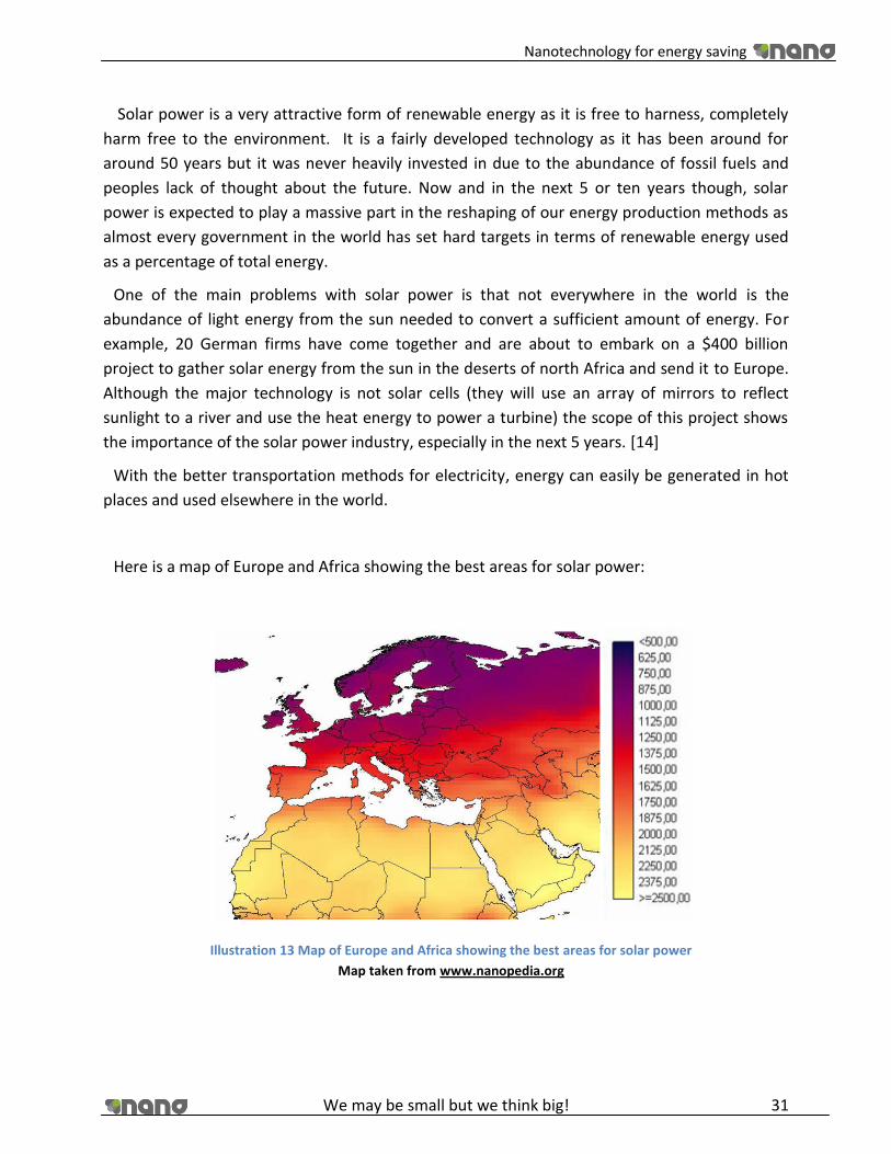
With the better transportation methods for electricity, energy can easily be generated in hot
places and used elsewhere in the world.
Here is a map of Europe and Africa showing the best areas for solar power:
Illustration 13 Map of Europe and Africa showing the best areas for solar power
Map taken from www.nanopedia.org

Nanotechnology for energy saving
We may be small but we think big! 32
The main applications of solar photovoltaic are:
Power stations: The largest one in the world is the Olmedilla Photovoltaic Park in
Spain, with 60MW;
Buildings: Generally, an array is incorporated into the roof or walls of a building
to supply it electricity;
Transport: Photovoltaic is rarely used to provide power in transport applications,
but is being increasingly used to provide auxiliary power in boats and cars;
Standalone devices: Photovoltaic is used as well to power calculators, parking
meters, emergency telephones, temporary traffic signs, and remote guard posts and
signals;
Rural electrification: In some rural locations the solar power is used to replace
kerosene lamps;
Solar roadways: In Idaho is testing the possibility of installing solar panels into the
road surface.[15]
5.1.2.1. Solar Cell Materials
There are 3 main types of solar cells that are commonly used.
1. Silicon Solar Cell
This is quite an efficient cell made from monocrystaline silicon which is the same raw material
used in the semiconductor industry. The efficiency of production models comes in at around
14% with results up to 25% in the laboratory. This can convert photons up to 1.15um in
wavelength. These solar cells are usually around 3mm thick with a diameter of 10-15cm. They
generate 35mA of electricity per square cm at a voltage of 550mV.each photon of light can only
stimulate 1 electron hole pair, this is part of the efficiency problem.
The cost of these panels to be installed in our house amounted to:
£659.99 for one panel of 120W
We need 12 panels for our roof, so 12x659.99= £7919.88
The installation cost is between £3000 and £20000, we will assume £11000 for
our study =£18919
A voltage regulator also has to be purchased to accompany the solar cells. This
costs £80
Total cost =£18999 [15]

Nanotechnology for energy saving
We may be small but we think big! 33
The following illustration shows how current output changes with ambient temperature, it can
be seen that a drop in temperature is an inconvenience to the silicon solar cell:
Illustration 14 Graph shows how current output changes with ambient temperature
Graph taken from http://www.sciencedirect.com
2. Amorphous/thin films
They are very cost effective and flexible, as it can be applied as a thin coating, this is useful as
it is easier to achieve the desired position of the solar panel so as to obtain optimum solar
energy. These cells have a very low efficiency though, around 8%. This is a high energy waste
which means we will not consider these for our conventional energy saving house. There is a
possibility that these could be used along with silicon panels however.
The cheapest available thin film solar cell was £269 for 120W with an installation cost of
£4000. This gives a total cost of £4349.
One disadvantage is the range of light they can take in. They take in all visible light up to blue
light wavelength. This is one of the efficiency setbacks.
3. Multi junction semiconductor
These cells consist of 2 or 3 layers of semi conductor material. They can achieve high
efficiencies of up to 34%. They are massively expensive so cannot be considered for our house,
they are mainly used for specialist applications such as feed satellites in space. The cost per unit
energy for these is higher than that of fossil fuels, so not practical at all for residential use. [15]

Nanotechnology for energy saving
We may be small but we think big! 34
5.1.2.2. Solar Panel Maintenance
Very little maintenance is needed for solar applications due to there being no moving parts.
Only the circulation pump is subject to physical wear. The panels need to be regularly checked
for damage caused by external elements such as the weather. This can be done by the
homeowner with use of simple instructions so there is no additional cost for this. [15]
5.1.2.3. Nano-solar cells
Nanotechnology, due to the material high surface area and high level of electrical conductivity,
can be used to improve the efficiency of solar panels/cells.
Here will be given a description of each of the nano solar cells available at the moment:
1. Organic dye sensitized solar cells
These devices work by absorbing a photon of light which forces an electron to move to the
TiO2 nano particle layer. They are 60% less expensive than silicon solar cells and have a very low
efficiency of around 10% in laboratory tests.
2. Quantum Dots
Quantum dots, also known as nanocrystals, are a special class of materials known as
semiconductors, which are crystals composed of periodic groups of II-VI, III-V, or IV-VI materials.
Semiconductors are a cornerstone of the modern electronics industry and make possible
applications such as the Light Emitting Diode and personal computer. Semiconductors derive
their great importance from the fact that their electrical conductivity can be dramatically
altered via an external stimulus (voltage, photon flux, etc), making semiconductors critical parts
of many different kinds of electrical circuits and optical applications. Quantum dots are unique
class of semiconductor because they are so small, ranging from 2-10 nanometers (10-50 atoms)
in diameter. At these small sizes materials behave differently, giving quantum dots
unprecedented tunability and enabling never before seen applications to science and
technology.
These may be used for decreasing the cost and increasing the efficiency of current silicon solar
cells. For every one photon of light that hits the cell, 3 electrons are excited and taken away to
be used as energy. This tells us that it is a very efficient device. A large amount of the spectrum
of light can be harnessed for energy use from these quantum dots when different sized particles
are placed in stacked layers, so less light is wasted compared to all other solar cells. The
efficiency of quantum dot solar cells is 86.5%. This is a very exciting and new technology and will
receive a lot of research attention in the coming years to try and push for its use commercially
so as governments can work to achieve their energy goals. [14]

Nanotechnology for energy saving
We may be small but we think big! 35
Here is a graph comparing most types of solar cell materials in terms of efficiency:
Illustration 15 Graph comparing most types of solar cell materials in terms of efficiency
Graph taken from http://www.sciencedirect.com
5.1.2.4. Calculations for Nano Solar Panels
The target of these calculations is torun our house with solar power photovoltaic. So, the first
study was done to reduce, as much as possible, the electricity consumption, maintaining the
maximum possible comfort.
First of all, we alculated the daily energy consumption:
Instantaneous power installed: 3611 W
Daily energy used: 2013.58 Wh/day
The power output of the converter should be 3611 W and the chosen converter has an
efficiency of 95% so, the power input should be:
Power input = Power output / converter efficiency = 3611 W / 0.95 = 3801.05 W

Nanotechnology for energy saving
We may be small but we think big! 36
We have to take in account that the converter has energy consumption; this consumption will
be the difference between:
(Power input – Power output) x (nº of hours working daily) =
(3801.05 W – 3611 W) x 8 hours = 1520.4 Wh
We will add up to the house energy consumption the converter energy consumption in order
to obtain the real daily consumption.
2013.5 W h / day + 1520.4 W h / day =3533.9 W h / day
Then, the electric current intensity each hour daily was calculated.
2013.5 W h / day + 1520.4 W h / day =3533.9 W h / day
I = 3533.9 W h /day / 24 V = 147.24 A h / day
To be certain that we have more than enough energy available we add up a 10% more.
147.24 A h/day + 14.72 = 161.95 A h / day
The solar energy level by Joules/squared meter in North West Poland is 11.5 Joules/m2.
So we can calculate with the peak solar hours with the next formula:
11.5 Kj / m2x 0.024x 0.0116 = 4.131 H.P.S.
We apply the gain tilt factor of the solar panels:
4.131 H.P.S. x 1.06 = 4.38 H.P.S
Intensity per panel = 175 W / 24 V = 7.29 A
Intensity of panel= I (each panel) x H.S.P. =7.29 A x 4.38 H.P. = 31.9 A h/ day.
Nº of panels necessaries: 161.95 A h/day / 31.9 A h / day = 5.08......6 panels
Intensity of batteries:
I (A) / depth of going flat x days of autonomy=
161.95 Ah / days/ 0.7= 231.35A x 3 days = 694.05 A h
Nº of batteries: 694.05 A h/ 350 A h =1.98.........2 batteries
Calculation of the intensity of regulatory:
I panel x nº of panels= 7.29 x 6 panels= 43.74 A..........50 A

Nanotechnology for energy saving
We may be small but we think big! 37
The solar energy level per day was taken from this graph of peak solar energy per day in
Poland:
Illustration 16 Graph of peak solar energy per day in Poland
Graph taken from www.strath.ac.uk
This graph, also from the same website was used to work out the best inclination levels for the
maximum energy:
Illustration 17 Graph was used to work out the best inclination levels for maximum energy
Graph taken from www.strath.ac.uk

Nanotechnology for energy saving
We may be small but we think big! 38
5.1.2.5. Cost Estimation for Solar Panels on House
As they are the most efficient nano product on the market at the moment, we ecided to use
Quantum Dots for our solar panels.
It was very difficult to find cost information on solar nanotechnology as it is only just coming
on to the market, but some websites gave us some information on its cost. The expected
market price for quantum dot solar panels will be $1 per Watt, so for our 3801.05 W total
power needs, the total cost of our panels will be $3801.5.
Plus an installation cost of $2000, which is typical for nano solar panels, we have a total cost of
$5801 for our panels.
5.1.2.6. Future Nano Solar Technology
All around the world scientists and engineers are working to explore the possibilities for
nanotechnology. The value of the nano market is expected to rise exponentially over the next 5
to 10 years such is our need for new sources of highly efficient green energy. Researchers at the
University of Singapore have recently discovered some interesting properties of nano size gold
when applied to photovoltaic solar panels. For example, then a thin layer of nano gold is
inserted between the anode and the photovoltaic efficiency of the solar cells is seen to increase
exponentially. These gold layers increase photocurrent efficiency by 16% and power conversion
efficiency by 7%. [15]
5.1.2.7. Conclusions
Finally, we can construct solar panels for our conventional energy saving house for £18999
which will see to our energy needs. However, when we use Quantum dots to construct our nano
solar panels, the cost amounts to $5801. It is therefore much cheaper and more
environmentally friendly to use nano materials to construct solar panels.
5.1.3. Wind Energy
One way of saving electricity is to produce this energy from renewable energy, like wind
energy.
Today, wind energy makes up 1% of global consumption of electricity (coming to represent
20% in Denmark and 10% in Spain).

Nanotechnology for energy saving
We may be small but we think big! 39
Wind energy can be harnessed by changing its kinetic energy into a rotary force, thence to electricity in
a wind turbine generator.
As the wind turbine does not produce emissions to the air,
land, or water, the wind power does not harm the
environment.
There has been a lot of talk about ‘noise pollution’
associated with running wind turbines. Mechanical sound
comes from the movement of the turbine’s components and
aerodynamic noise is discernible from the whirling blades.
With a wind speed of 8 m/s, the sound emitted by a single
small wind turbine is equivalent to that of a domestic
refrigerator.
The payback time for wind power depends on the
wind conditions, the amount of electricity generated,
and the total cost of electricity, taking into account
taxation, the power transmission charge, and the price
per kilowatt.
Today when the people listening talk about the wind
power, generally associate it with large wind turbines
located along sea coasts, but with small turbines is possible
to produce electricity locally for private use by industry,
farms, leisure homes and households. [16]
In the next figure we can see that in the year 2020 in Poland, the total number domestic of thewind
turbines installed will be approximately 600.
Illustration 19 Graph with the number of the wind turbines installed in 2020
Graph taken of “The wind power development in Poland by 2020- a visión”
The best possible siting for a wind turbine is an open area. This may or may not also be higher
than its surroundings. An ideal installation places include the sea coast, the banks of inland
lakes, large fields or meadows, and hill summits. The essential factor from the operating
standpoint is for there to be as much empty space as possible towards the prevailing wind.
Illustration 18 Drawing of the rotor and blades of a wind turbine. Picture taken from
http://www.cecu.es/campanas/medio%20ambiente/res&rue/htm/guia/eolica.htm

Nanotechnology for energy saving
We may be small but we think big! 40
5.1.3.1. Study of wind turbines for a modern house
For small facilities or agricultural household wind turbines more useful and accessible are
those with a diameter of 1-5 sweep m, capable of generating 400 W to 3.2 kW.
They have the advantage, moreover, that can boot to a wind speed lower than the larger,
slower winds may take (such as sea breezes and mountain winds) and produce more energy.
They need a minimum wind speed of 3 m/s to boot (compared to 5.30 m/s of the largest), get
maximum performance at 12.5 m/s and stand with winds of over 28 m/s in order to avoid
damage, wear or overheating in its mechanism. The cost of residential turbine installations
between 1.5 and 10 kW can vary between 13,000 and 40,000 €.
The energy produced by a wind turbine varies according to the diameter of the turbine blades
and the height of the tower, but also influences the wind strength, the time to work and the
orographic characteristics in the field, is for these reasons that we can only make an estimate of
the energy produced by wind turbines installed. For more accuracy would require the study of
maps of wind and a record of wind resource data the exact location of the wind turbine
(frequency, velocity, duration and wind direction) for several months.
The wind turbine must be minimum 6m taller that the interferences such as house, trees or
any objects. It also has to be placed in distance about 76m from them.
The cost of installation may vary due to transport costs, different tower heights, different rotor
diameters, the rating of the turbine, type of charge controller, battery type and the type of
inverter.
To estimate the cost of installation and the energy produced by the turbine, we have based on
the parameters described above, and we choose the system best suited to our conditions and
needs. [17]
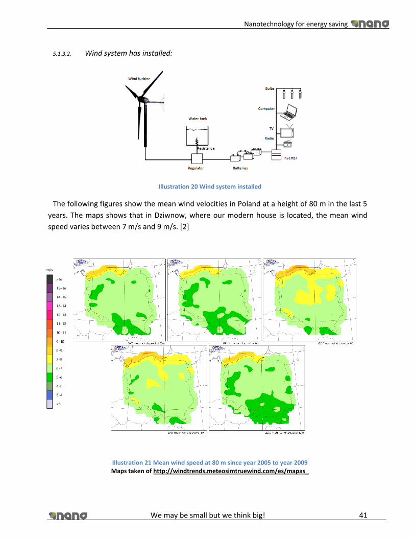
Nanotechnology for energy saving
We may be small but we think big! 41
5.1.3.2. Wind system has installed:
Illustration 20 Wind system installed
The following figures show the mean wind velocities in Poland at a height of 80 m in the last 5
years. The maps shows that in Dziwnow, where our modern house is located, the mean wind
speed varies between 7 m/s and 9 m/s. [2]
Illustration 21 Mean wind speed at 80 m since year 2005 to year 2009 Maps taken of http://windtrends.meteosimtruewind.com/es/mapas_

Nanotechnology for energy saving
We may be small but we think big! 42
There are several possible wind turbine of different companies, is necessary chose the best for
our conditions. [18] [19]
We choose the Skytream 3.7 of the company Skytream.
Table 2 Technical characteristics of the selected wind turbine
Illustration 22 Power of wind speed
Graphs taken of http://www.windenergy.com
WIND TURBINE
Installation company Skystream
Skystream 3.7 2,4 kW
Rated speed 50-330 rpm
Blade material Fiberglass reinforced composite
Blade quantity 3
Rotor blade diameter 3.72 m
Minimum start-up wind speed 3.5 m/s
Weight 77 kg
Yaw control passive
Survival wind 63.0 m/s (max.)
Alternator Slotless permanent magnet brushless
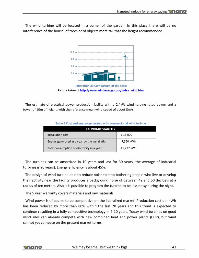
Nanotechnology for energy saving
We may be small but we think big! 43
The wind turbine will be located in a corner of the garden. In this place there will be no
interference of the house, of trees or of objects more tall that the height recommended.
Illustration 23 Comparison of the scale
Picture taken of http://www.windenergy.com/index_wind.htm
The estimate of electrical power production facility with a 2.4kW wind turbine rated power and a
tower of 10m of height; with the reference mean wind speed of about 8m/s.
Table 3 Cost and energy generated with convencional wind turbine
ECONOMIC VIABILITY
Installation cost € 15,000
Energy generated in a year by the installation 7,560 kWh
Total consumption of electricity in a year 11,237 kWh
The turbines can be amortized in 10 years and last for 30 years (the average of industrial
turbines is 20 years). Energy efficiency is about 45%.
The design of wind turbine able to reduce noise to stop bothering people who live or develop
their activity near the facility produces a background noise of between 42 and 50 decibels at a
radius of ten meters. Also it is possible to program the turbine to be less noisy during the night.
The 5 year warranty covers materials and raw materials.
Wind power is of course to be competitive on the liberalized market. Production cost per kWh
has been reduced by more than 80% within the last 20 years and this trend is expected to
continue resulting in a fully competitive technology in 7-10 years. Today wind turbines on good
wind sites can already compete with new combined heat and power plants (CHP), but wind
cannot yet compete on the present market terms.
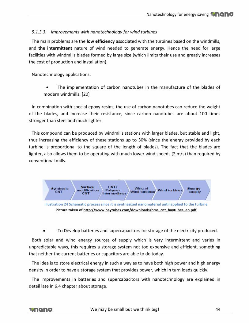
Nanotechnology for energy saving
We may be small but we think big! 44
5.1.3.3. Improvements with nanotechnology for wind turbines
The main problems are the low efficiency associated with the turbines based on the windmills,
and the intermittent nature of wind needed to generate energy. Hence the need for large
facilities with windmills blades formed by large size (which limits their use and greatly increases
the cost of production and installation).
Nanotechnology applications:
The implementation of carbon nanotubes in the manufacture of the blades of
modern windmills. [20]
In combination with special epoxy resins, the use of carbon nanotubes can reduce the weight
of the blades, and increase their resistance, since carbon nanotubes are about 100 times
stronger than steel and much lighter.
This compound can be produced by windmills stations with larger blades, but stable and light,
thus increasing the efficiency of these stations up to 30% (since the energy provided by each
turbine is proportional to the square of the length of blades). The fact that the blades are
lighter, also allows them to be operating with much lower wind speeds (2 m/s) than required by
conventional mills.
Illustration 24 Schematic process since it is synthesized nanomaterial until applied to the turbine
Picture taken of http://www.baytubes.com/downloads/bms_cnt_baytubes_en.pdf
To Develop batteries and supercapacitors for storage of the electricity produced.
Both solar and wind energy sources of supply which is very intermittent and varies in
unpredictable ways, this requires a storage system not too expensive and efficient, something
that neither the current batteries or capacitors are able to do today.
The idea is to store electrical energy in such a way as to have both high power and high energy
density in order to have a storage system that provides power, which in turn loads quickly.
The improvements in batteries and supercapacitors with nanotechnology are explained in
detail late in 6.4 chapter about storage.

Nanotechnology for energy saving
We may be small but we think big! 45
5.1.3.4. Market
Every year the number of installations of the residential wind turbines in the world increases.
For the year 2020 the expected is increased about 600% of domestic wind turbines installed in
Poland. Due to this fact and reduced price of the carbon nanotubes, expected a significant
increase in the manufacturing wind turbines using the nanoparticles for make it.
In the following graph can see that the global nanomaterial demand will grow annually by 33%
per year between 2003 and 2020.
Illustration 25 Graph World nanomaterials demand
Graph taken of NRM_Energy
Nowadays there is one company working with carbon nanotubes for the production of blades.
Is a Finnish company, whose name is Eagle Tuulivoima that uses nanomaterials from Bayer
MaterialScience (carbon nanotubes manufactured for the company Bayer).
The company started manufacturing two models, one with 2 kilowatts and another with 5
kilowatts of rated output and after the expansion of another to models more with 10 and 20
kilowatts.
Eagle Tuulivoima expected that the cost decrease to the €10,000 of installation for a wind
turbine of two kilowatts. The electric power produced in a year for this kind of turbines is
estimate in 4,000 to 8,000 kilowatts hours depending of the location of the windmills. [21]
A wind turbine of this size could provide the electric power that need a single-family home
with average consumption.

Nanotechnology for energy saving
We may be small but we think big! 46
Table 4 Technical characteristics of one wind turbine with nanotubes
WIND TURBINE Installation company Eagle power
Eaglepower 2 Rated Power 2000 W
Output voltage AC230 V
Blade material Hybtonite
Blade quantity 3 typical HAWT
Rotor blade diameter 4.5 m
Minimum start-up wind speed 2.5 m/s
Rated wind speed 9 m/s
Rated rotating rate 250 r/min
Generator output 3-phase
Output AC frequency 50/60 Hz
Tower height 6-30 m
Weight of generator 182 kg
Protection against strong winds mechanical
Survival wind 50.0 m/s (max.)
5.1.3.5. Carbon Nanotubes [3] [22] [23] [24]
Carbon nanotubes which are long thin cylinders of carbon, were discovered in 1991 by S.
Iijima. These are large macromolecules that are unique for their size, shape and extraordinary
physical properties. Can be considered as a sheet of graphite (a hexagonal netting carbon) rolled
into a cylinder. These intriguing structures have generated much enthusiasm in recent years and
a great deal of research has been devoted to its understanding.
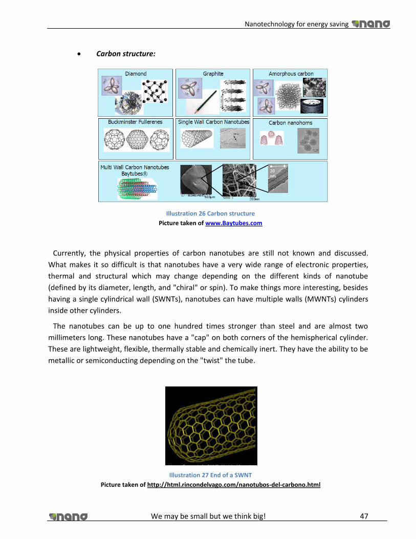
Nanotechnology for energy saving
We may be small but we think big! 47
Carbon structure:
Illustration 26 Carbon structure
Picture taken of www.Baytubes.com
Currently, the physical properties of carbon nanotubes are still not known and discussed.
What makes it so difficult is that nanotubes have a very wide range of electronic properties,
thermal and structural which may change depending on the different kinds of nanotube
(defined by its diameter, length, and "chiral" or spin). To make things more interesting, besides
having a single cylindrical wall (SWNTs), nanotubes can have multiple walls (MWNTs) cylinders
inside other cylinders.
The nanotubes can be up to one hundred times stronger than steel and are almost two
millimeters long. These nanotubes have a "cap" on both corners of the hemispherical cylinder.
These are lightweight, flexible, thermally stable and chemically inert. They have the ability to be
metallic or semiconducting depending on the "twist" the tube.
Illustration 27 End of a SWNT
Picture taken of http://html.rincondelvago.com/nanotubos-del-carbono.html
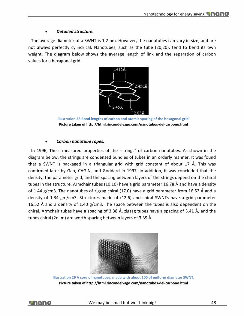
Nanotechnology for energy saving
We may be small but we think big! 48
Detailed structure.
The average diameter of a SWNT is 1.2 nm. However, the nanotubes can vary in size, and are
not always perfectly cylindrical. Nanotubes, such as the tube (20,20), tend to bend its own
weight. The diagram below shows the average length of link and the separation of carbon
values for a hexagonal grid.
Illustration 28 Bond lengths of carbon and atomic spacing of the hexagonal grid.
Picture taken of http://html.rincondelvago.com/nanotubos-del-carbono.html
Carbon nanotube ropes.
In 1996, Thess measured properties of the "strings" of carbon nanotubes. As shown in the
diagram below, the strings are condensed bundles of tubes in an orderly manner. It was found
that a SWNT is packaged in a triangular grid with grid constant of about 17 Å. This was
confirmed later by Gao, CAGIN, and Goddard in 1997. In addition, it was concluded that the
density, the parameter grid, and the spacing between layers of the strings depend on the chiral
tubes in the structure. Armchair tubes (10,10) have a grid parameter 16.78 Å and have a density
of 1.44 g/cm3. The nanotubes of zigzag chiral (17.0) have a grid parameter from 16.52 Å and a
density of 1.34 gm/cm3. Structures made of (12.6) and chiral SWNTs have a grid parameter
16.52 Å and a density of 1.40 g/cm3. The space between the tubes is also dependent on the
chiral. Armchair tubes have a spacing of 3.38 Å, zigzag tubes have a spacing of 3.41 Å, and the
tubes chiral (2n, m) are worth spacing between layers of 3.39 Å.
Illustration 29 A cord of nanotubes, made with about 100 of uniform diameter SWNT.
Picture taken of http://html.rincondelvago.com/nanotubos-del-carbono.html

Nanotechnology for energy saving
We may be small but we think big! 49
Properties
In general the properties of nanotubes depend mainly on the following factors: the number of
concentric layers it has, how they are rolled and the diameter of the nanotube.
Electronic Properties
- They conduct electrical current.
- They can act similar to metals (they act as semiconductors or even superconductors).
Mechanical Properties.
- Using nano materials we can get materials as hard as dimond
- It has a high "mechanical strength".
- It has a high flexibility.
Elastic Properties
- Because of its geometry, the nanotubes could be expected to be extremely hard in the
direction of the shaft, but instead are flexible to deformation perpendicular to the axis.
- The curvature causes increased energy: carbon nanotubes are less stable than graphite, and
the smaller the diameter the lower stability.
- For large radial deformations, nanotubes may be unstable. This occurs mainly for large
diameter nanotubes.
- The mechanical properties of nanotubes are superior to carbon fiber, partial resistance to
deformation, flexibility, etc. Which make them suitable for many applications.
Thermal Properties
- It features high thermal conductivity in the direction of the axis of the nanotube.
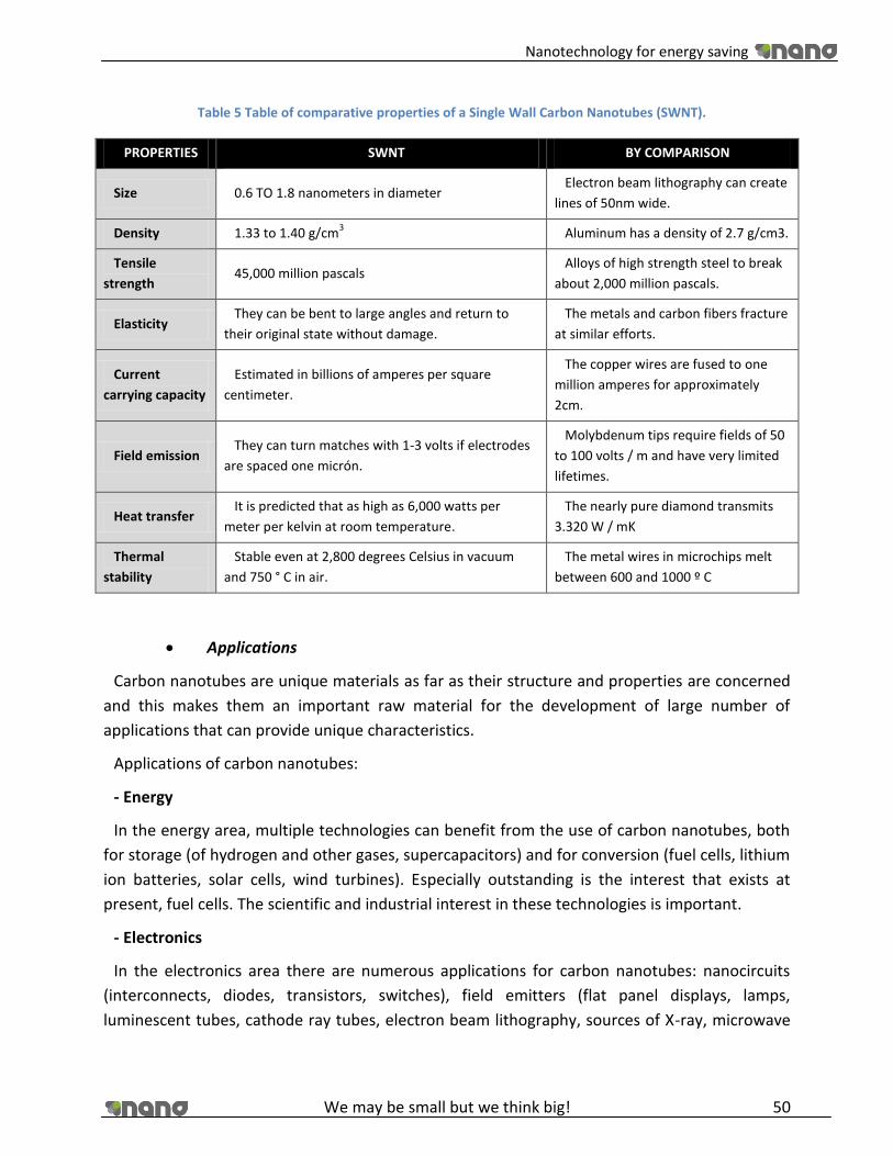
Nanotechnology for energy saving
We may be small but we think big! 50
Table 5 Table of comparative properties of a Single Wall Carbon Nanotubes (SWNT).
PROPERTIES SWNT BY COMPARISON
Size 0.6 TO 1.8 nanometers in diameter Electron beam lithography can create
lines of 50nm wide.
Density 1.33 to 1.40 g/cm3 Aluminum has a density of 2.7 g/cm3.
Tensile
strength 45,000 million pascals
Alloys of high strength steel to break
about 2,000 million pascals.
Elasticity They can be bent to large angles and return to
their original state without damage.
The metals and carbon fibers fracture
at similar efforts.
Current
carrying capacity
Estimated in billions of amperes per square
centimeter.
The copper wires are fused to one
million amperes for approximately
2cm.
Field emission They can turn matches with 1-3 volts if electrodes
are spaced one micrón.
Molybdenum tips require fields of 50
to 100 volts / m and have very limited
lifetimes.
Heat transfer It is predicted that as high as 6,000 watts per
meter per kelvin at room temperature.
The nearly pure diamond transmits
3.320 W / mK
Thermal
stability
Stable even at 2,800 degrees Celsius in vacuum
and 750 ° C in air.
The metal wires in microchips melt
between 600 and 1000 º C
Applications
Carbon nanotubes are unique materials as far as their structure and properties are concerned
and this makes them an important raw material for the development of large number of
applications that can provide unique characteristics.
Applications of carbon nanotubes:
- Energy
In the energy area, multiple technologies can benefit from the use of carbon nanotubes, both
for storage (of hydrogen and other gases, supercapacitors) and for conversion (fuel cells, lithium
ion batteries, solar cells, wind turbines). Especially outstanding is the interest that exists at
present, fuel cells. The scientific and industrial interest in these technologies is important.
- Electronics
In the electronics area there are numerous applications for carbon nanotubes: nanocircuits
(interconnects, diodes, transistors, switches), field emitters (flat panel displays, lamps,
luminescent tubes, cathode ray tubes, electron beam lithography, sources of X-ray, microwave

Nanotechnology for energy saving
We may be small but we think big! 51
amplifiers, gas discharge tubes in telecom networks, electron microscopes, nanotriodos,
betatrons), RF filters, memory, optoelectronics, recorded and spintronics. Foremost among all
field emission, in particular, flat panel displays. There are now prototypes of memories, field
emission lamps, X-ray sources, oscillators, diodes and field emission displays.
Although not yet commercialized electronic products incorporating carbon nanotubes, is
expected to happen in the not too distant future and at that time will revolutionize the market
by offering speed, miniaturization and long life.
- Sensors
Carbon nanotubes can be used to develop chemical sensors / biological, mechanical, thermal,
electromagnetic field emission. Which aroused the most interest are the biological and chemical
for its potential use in the detection of pollutants and for use in biological environments. There
are now prototypes of sensors for heavy metals in water and debuggers for fluids.
- Scientific Instrumentation
Carbon nanotubes can be used for the manufacture of probe tips of scanning probe
microscopes, as well as coulter counter membranes. Volume results highlight the scanning
probe microscopes and, within them, the AFM (Atomic Force Microscope). A prototype of the
AFM probe tip.
- Photonics
In the area of photonics, carbon nanotubes will improve existing devices and also be the basis
for the emergence of new ones that will increase the independence of the photon with respect
to electronics. The main applications identified are high-pass filters for light, saturable absorber
mirrors for passive mode blocker emitting laser pulses, noise suppressors and switches.
- Materials
Nanorreforzados materials with carbon nanotubes are obtained by dispersing them in a matrix
of another material. In this manner, new materials with interesting mechanical, electrical,
electrorreológicas, hydrophobic, flame retardants, optical, chemical and thermal. Among the
materials reinforced with carbon nanotubes for structural highlights, which exploit the
mechanical properties of carbon nanotubes resulting composite lightweight and high
mechanical strength.
There is a high degree of overlap of this application with others so, for example, for the
development of some electronic products using composite materials containing carbon
nanotubes, - while in other cases individual nanotubes are used and the same applies in other
areas.
They are marketed as sports equipment made from composite materials incorporating carbon
nanotubes, such as baseball bats, bicycles, tennis rackets, badminton rackets or hockey sticks.

Nanotechnology for energy saving
We may be small but we think big! 52
The market for materials is presented and the most advanced of all the potential applications of
carbon nanotubes.
- Biotechnology and Chemistry
There are a number of potential biotechnological and chemical applications for carbon
nanotubes: adsorption and absorption, catalysis, electrosynthesis and medicine. Stresses in a
special way medicine where carbon nanotubes pose an extraordinary revolution in different
aspects such as administration of drugs
- Mechanics
Have been identified in this area the use of carbon nanotubes for the development of
actuators, dampers, fluid devices, tribology, NEMS and MEMS.
Table 6 Examples of some applications
APPLICATIONS THE IDEA
Chemical and genetic probes "DNA
Strands"
A microscope with a nanotube tip can locate a strand of DNA and identify the chemical markers that reveal which of the possible variables of a gene with the thread
Mechanical memory "RAM nonvolatile" It has tested a screen of nanotubes deposited on a support block as a function of binary memory devices, voltages forcing contact between tubes ("on" state) or separation ("off" state)
Nano-tweezers Two nanotubes attached to electrodes on a glass rod, open and close via a voltage change. These clamps are used to imprison and move objects 500 nanometers in size.
Supersensitive sensors Semiconductor nanotubes a resistance change drastically when exposed to alkalis, halogens and other gases at room temperature. Hence the hope of achieving better chemical sensors.
Hydrogen and ion storage The nanotubes could store hydrogen in its interior cavity and gradually release it in fuel cells cheaper and more efficient. Also home to lithium ion batteries that could lead to longer term.
Maximum strength materials Embedded in a composite material, the nanotubes enjoy enormous elasticity and tensile strength. Could be used in cars that bounce off buildings in an accident or an earthquake hover instead of cracking.
Scanning microscope higher resolution
"This application is ready for market"
Attached to the tip of a scanning probe microscope, the nanotubes can amplify the lateral resolution of the instrument factor of ten or more, allowing clear representations of proteins and other molecules.
Mechanical oscillator "theoretical
versions"
An internal nanotube could range at frequencies of the order of giga-hertz in a nanotube higher under the influence of Van der Waals forces.
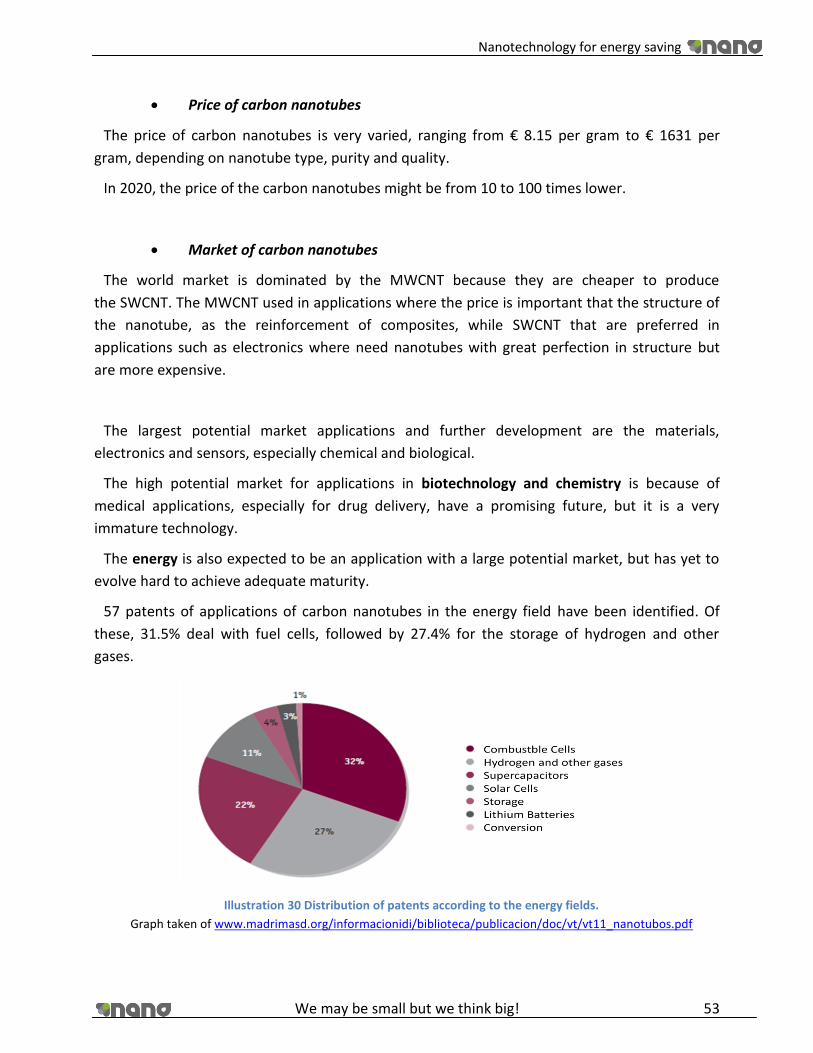
Nanotechnology for energy saving
We may be small but we think big! 53
Price of carbon nanotubes
The price of carbon nanotubes is very varied, ranging from € 8.15 per gram to € 1631 per
gram, depending on nanotube type, purity and quality.
In 2020, the price of the carbon nanotubes might be from 10 to 100 times lower.
Market of carbon nanotubes
The world market is dominated by the MWCNT because they are cheaper to produce
the SWCNT. The MWCNT used in applications where the price is important that the structure of
the nanotube, as the reinforcement of composites, while SWCNT that are preferred in
applications such as electronics where need nanotubes with great perfection in structure but
are more expensive.
The largest potential market applications and further development are the materials,
electronics and sensors, especially chemical and biological.
The high potential market for applications in biotechnology and chemistry is because of
medical applications, especially for drug delivery, have a promising future, but it is a very
immature technology.
The energy is also expected to be an application with a large potential market, but has yet to
evolve hard to achieve adequate maturity.
57 patents of applications of carbon nanotubes in the energy field have been identified. Of
these, 31.5% deal with fuel cells, followed by 27.4% for the storage of hydrogen and other
gases.
Illustration 30 Distribution of patents according to the energy fields.
Graph taken of www.madrimasd.org/informacionidi/biblioteca/publicacion/doc/vt/vt11_nanotubos.pdf
Nanotechnology for energy saving
We may be small but we think big! 54
The search for solutions based on carbon nanotubes for the development of fuel cells is the
most frequent subject.
The mechanics, photonics and scientific instruments are some mature technologies as well,
with less market potential that all the applications mentioned earlier.
The main countries that publish scientific references are U.S., China, Japan and Korea, so that,
although U.S. the leading country, the total Asian publications exceed the U.S. Europe lags
behind U.S. and Asia in terms of number of scientific references.
In patents there is a clear American leadership over the other regions, followed by Asia and
Europe. These data are a clear reflection of the strong interest of U.S. industrial firms in the
applications of carbon nanotubes as they have a very diverse market in which output can have a
multitude of products.
In the field of Energy United States is again the leader in number of patents, followed by two
Asian countries: Japan and Taiwan.
In general the market for applications of carbon nanotubes is very new. Except for some
composite materials, the remaining applications are not yet marketed, some already exist as
prototypes and other opportunities only arise as a result of future scientific research.
For applications of carbon nanotubes from breaking permanently to the market needs to
move forward on many fronts. Nanotube suppliers must improve the quantity, quality and price
of producing nanotubes, and their ability to adapt to the requirements of its customers and
application vendors must find new ways to manipulate the nanotubes to develop their products
by industrial processes.
Thus, it is observed that carbon nanotubes have enormous scientific and industrial interest.
Their use in the development of numerous applications can bring to these important
improvements to make a significant commercial impact and will result therefore in great
benefits for companies that produce them.

Nanotechnology for energy saving
We may be small but we think big! 55
5.2. Conversion
5.2.1. Illumination.
1. LED technology.
LED acronym means “Light Emitting Diode”.The diode is a semiconductor light source. It is a
device that emits incoherent narrow-spectrum light when polarized directly the PN junction of
it. This phenomenon is a form of electroluminescence
CATHODEANODE -+
Illustration 31 LED diode symbolic representation.
The first LED was developed in 1927 by Oleg Vladimirovich Losev, however not used in the
industry until the 1960s. It could be built only red, green and yellow in low light intensity and
limited their use for remote controls and appliances to mark the on and off. At the end of the
twentieth century were invented ultraviolet and blue LEDs, which gave way to the development
of white LED, a blue light LED with phosphor coating that produces a yellow light, the mixture of
blue and yellow produces a white light called “Moonlight” getting high luminosity (7 lumens
each) thus has expanded its use in lighting systems
Today, are developing and beginning to market LEDs with performance than those of recent
years and with a promising future in various fields, including general lighting applications. As an
example, we can emphasize that Nichia Corporation has developed a white light LEDs with a
luminous efficiency is even higher than the vapor lamp, high pressure sodium (132 lm/W),
which is considered one of the most efficient light sources.
Spontaneous emission therefore does not occur significantly in all the diodes is only visible as
visible light LEDs, which have a particularly constructive approach in order to avoid radiation is
absorbed by the surrounding material and a band gap energy corresponding to coincide with
the visible spectrum. In other diodes, the energy is released mainly as a heat, infrared radiation
or ultraviolet radiation. In the case of the diode released in the form of ultraviolet, you can get
to take this radiation to produce visible radiation, using fluorescent or phosphorescent
substances that absorb ultraviolet radiation emitted by the diode and then emit visible light.

Nanotechnology for energy saving
We may be small but we think big! 56
2. LED illumination, advantages and disadvantages.
The future bulbs for illuminating a house seem to be the LED bulbs; actually is impossible to
compare in terms of efficiency the incandescent conventional bulbs with LED bulbs.
Advantages of LED illumination:
Lower power consumption: LED lamp is powered at low voltage and low power
consumption.
For example: A 50 W halogen lamp light power 25 lumens/ W by getting a total of 1250 lumens.
To achieve the same illumination LED lamp we will need 179 LEDs (using high brightness LEDs
that illuminate 7 lumens/ unit), thus we have the same lighting with lamps and yet both our
consumption with the LED lamp will be four times smaller and consumes only 13 W
approximately.
Low voltage: All our products are fed to 24 V DC, perfectly adapted to most of the
power supplies of equipment, and minimizing the risks of electrocution. The range of
voltages is between 12 and 250 V. In our house the voltage will be 230V.
Faster response: The LED has an answer much faster performance than halogen and
fluorescent, the order of few microseconds, this makes it ideal for use with a strobe
(strobe systems), thereby increasing the benefits of the latter.
Low temperature: LED is powered by low voltage and consumes little energy and
therefore emits little heat. This is because LED is a device that operates at a low
temperature relative to the light that it provides. Other lighting systems equal brightness
LED emits much more heat.
Small spectral width: The LEDs have a small spectral width, thus making them the
perfect system of lighting for machine vision, because this way the camera captures
much more detail subject and can better appreciate the potential weaknesses therein.
Wide spectral band: The LED is a fixed wavelength device but can work in a wide band of
the spectrum. To cover all the bandwidth available on the market a wide range of LED
that will allow us to light with a wavelength specifies, or which is the same in particular
color (red, green, amber, white and even ultraviolet).
Brighter light: In the same conditions of luminosity as their rivals, the light emitted from
the LED is much shaper and brighter.
Durability and reliability: The life of a LED is very long compared to other lighting
systems.
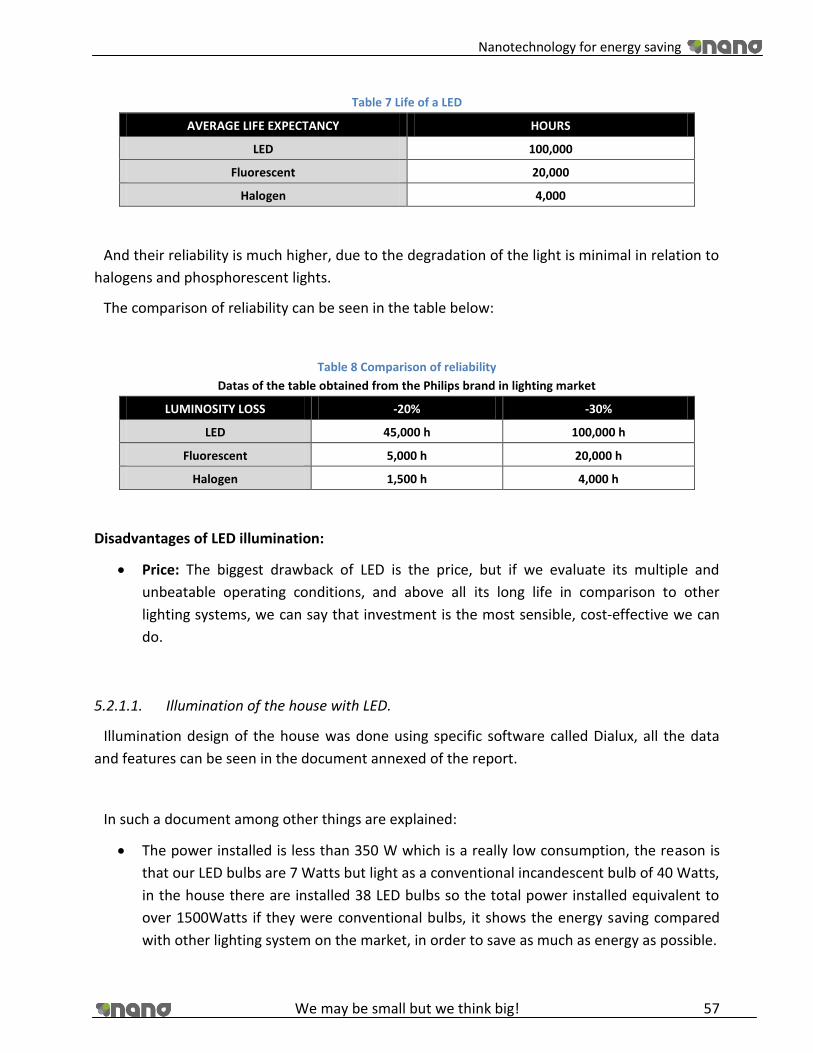
Nanotechnology for energy saving
We may be small but we think big! 57
Table 7 Life of a LED
AVERAGE LIFE EXPECTANCY HOURS
LED 100,000
Fluorescent 20,000
Halogen 4,000
And their reliability is much higher, due to the degradation of the light is minimal in relation to
halogens and phosphorescent lights.
The comparison of reliability can be seen in the table below:
Table 8 Comparison of reliability
Datas of the table obtained from the Philips brand in lighting market
LUMINOSITY LOSS -20% -30%
LED 45,000 h 100,000 h
Fluorescent 5,000 h 20,000 h
Halogen 1,500 h 4,000 h
Disadvantages of LED illumination:
Price: The biggest drawback of LED is the price, but if we evaluate its multiple and
unbeatable operating conditions, and above all its long life in comparison to other
lighting systems, we can say that investment is the most sensible, cost-effective we can
do.
5.2.1.1. Illumination of the house with LED.
Illumination design of the house was done using specific software called Dialux, all the data
and features can be seen in the document annexed of the report.
In such a document among other things are explained:
The power installed is less than 350 W which is a really low consumption, the reason is
that our LED bulbs are 7 Watts but light as a conventional incandescent bulb of 40 Watts,
in the house there are installed 38 LED bulbs so the total power installed equivalent to
over 1500Watts if they were conventional bulbs, it shows the energy saving compared
with other lighting system on the market, in order to save as much as energy as possible.

Nanotechnology for energy saving
We may be small but we think big! 58
We have chosen Philips lamps due to is a brand with a wide range of possibilities in LED
lighting concerns, and their catalogues has a very good data specifications to make
calculations on efficiency and energy saving.
Is one of the most popular illumination brands and very compromised with the
environment.
Is a brand with a lot of experience and the reliability is guaranteed.
Offers plug inns compatibles with Dialux to compare results and even to check the
results in 3D.
The chosen lamps are the model PHILIPS Leuchten Lux Space MiniBBS481 1xDLED-3000
PSU-E WH, all features are fully explained in Annex III.
Technical specifications of the chosen LED bulbs by Philips:
Philips - Econic Bulb 7 W (40 W) Bayonet cap Warm white - G08727900871739 -
EEL: A
Shape: Bulb
Light effect: Warm white
Wattage: 7 W
Wattage standard bulb: 40 W
Fitting/Cap: B22
Voltage: 230–240 V
Dimmable: yes
Lifetime of lamps: 25 year(s)
Lifetime of lamps: 25,000 hour(s)
5.2.1.2. How to improve LED illumination with nanotechnology.
Everybody knows that the LED bulbs are much more expensive than incandescent bulbs,
maybe 3 or 4 times more, but they produce about twice as much light per watt; they last up to
50,000 hours or 50 times as long as a 60-watt bulb; and they are very tough and hard to break.
Because they are made in a fashion similar to computer chips, the cost of LEDs has been
Illustration 32 Bulb Picture taken from www.philips .com

Nanotechnology for energy saving
We may be small but we think big! 59
dropping steadily. The Department of Energy of the US has estimated that LED lighting could
reduce energy consumption of the country for lighting by 29 percent by 2025, saving the
nation’s households about $125 billion in the process. We are without any doubt to the future
of lighting technology.
But, how does it exactly work? , we will see in the next point that the quantum dots are a
nanotechnology application used to improve the LED illumination. [25]
5.2.1.3. Quantum dots
5.2.1.4. Applications of quantum dots
The main applications that the researchers are studying nowadays are basically in the
following four areas:
Optoelectronics, Biomedicine, Experimental Solar Panels, Illumination Systems.
We are going to explain a little bit of each application in order to know what could be achieved
exactly in the near future with quantum nanodots technology. However in this project we only
focus our research of quantum dots in the areas such as experimental solar panels (in the
section of generation), and Illumination systems (in this section).
Optoelectronics: Light-emitting diode lasers are being improved using quantum dots
made of indium arsenide and indium phosphide. It seems will be used to make the
futures new CD players, barcode machines and things like that to medium term.
Illustration 33 Size of the quantum dots. Pictures taken from http://www.nanomaterialstore.com

Nanotechnology for energy saving
We may be small but we think big! 60
Biomedicine: In this area the application of the quantum dots are very revolutionary,
due their good illumination properties is possible to insert it in the human body in order
to illuminate areas that could be impossible to see without this technology, such tumors,
and other cells. It allows do very exacting diagnosis and detecting diseases that before
were imperceptibles. Quantum dots emit bright and very stable and there is no fear of
being shut down.
Experimental Solar Panels: The third generation of photovoltaic cells used, among other
possibilities, surfaces with quantum dots. The yeld is higer than the cells of first and
second generation and manufacturing is cheaper. Quantum dots are manufacturing
cheap, and can do their work also cheap production. A working quantum point polymer
could place, eventually, solar electricity equal to one-off electricity from coal. If this
could be done, would be revolutionary. A cell quantum dot solar business is still years
away assuming it is possible. But so, would help overcome this fossil fuel.
Illumination Systems: As we have seen previously, with quantum dots it is possible to
achieve new lighting systems with more efficient performance.[31]
Some data and publications: [30]
“In lighting, quantum dots allow the colour of the light from a light source to be precisely
controlled, says Jason Hartlove, the chief executive of Nanosys, based in Palo Alto, California—
one of a handful of companies making quantum dots and selling lighting components based on
them.” The Economist, March 4th, 2010.Quantum Dots: A quantum leap for lighting. [30]
Report of global market of Quantum Dots:
Illustration 34 Global market growth for quantum dots in promising commercial market sectors, 2008-2013 ($
Millions)
Graph taken from BBC research Report code : NANO27B, Published: September 2008, Analyst: John Oliver

Nanotechnology for energy saving
We may be small but we think big! 61
Phosphor dots shown under UV excitation. [29]
Illustration 35 Phosphor dots shown under UV excitation.
Picture taken from http://www.nanomaterialstore.com/nano-phosphor.php
We know too well that LED technology is the lighting system is more efficient and has better
future. However it has some points that could be even better. For example, the color quality,
but that is comes to solving a new breakthrough developed by nanotechnology. Current
methods for increasing this visual performance are too expensive, too power hungry, and
compromise on brightness.
A phosphor material created from nanomaterials was developed, that increases the brightness
of the colors of LED lights which can be incorporated into any lamp or device that uses LEDs as a
layer. The best thing about this system , apart from that can generate a spectrum of vivid colors,
is that it does so without increasing power consumption and also makes it can easily incorporate
the devices without having to significantly modify their production systems.
Now, unlike organic LEDs are polymeric LEDs (PLEDs), where the latter presented a dissolution
process, which is much easier and cheaper costs. Currently, improve their performance has
been the focused target of much research and developments within the last two decades.
One application would be the integration of nanostructures in the PLED, incorporating self-
assembled organic nanowires to these duplicate the performance.
The system is quite simple; the best thing is that, unlike others, it is not to reinvent the
technology from the beginning. The manufacturers would only have to implement this layer in
the manufacturing chain and to use. In addition, the system could also improve the laptop
displays or HD TV, and without increasing power consumption.
Nanosys: Is a Company founded in 2001 to drive materials revolution, located in Palo Alto,
California. Nanosys (Palo Alto) designs products based on a technology platform that
incorporates high performance inorganic nanostructures. This technology is currently being
applied to address opportunities in LED general lighting among other things.
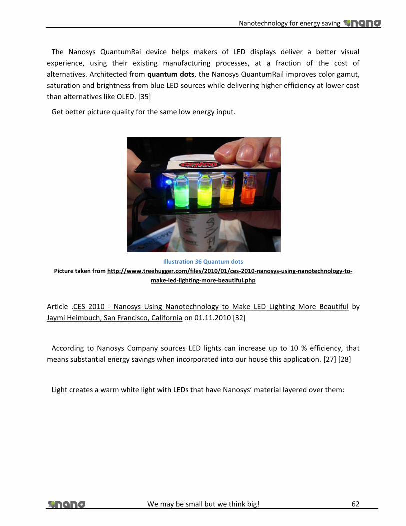
Nanotechnology for energy saving
We may be small but we think big! 62
The Nanosys QuantumRai device helps makers of LED displays deliver a better visual
experience, using their existing manufacturing processes, at a fraction of the cost of
alternatives. Architected from quantum dots, the Nanosys QuantumRail improves color gamut,
saturation and brightness from blue LED sources while delivering higher efficiency at lower cost
than alternatives like OLED. [35]
Get better picture quality for the same low energy input.
Illustration 36 Quantum dots
Picture taken from http://www.treehugger.com/files/2010/01/ces-2010-nanosys-using-nanotechnology-to-
make-led-lighting-more-beautiful.php
Article .CES 2010 - Nanosys Using Nanotechnology to Make LED Lighting More Beautiful by
Jaymi Heimbuch, San Francisco, California on 01.11.2010 [32]
According to Nanosys Company sources LED lights can increase up to 10 % efficiency, that
means substantial energy savings when incorporated into our house this application. [27] [28]
Light creates a warm white light with LEDs that have Nanosys’ material layered over them:

Nanotechnology for energy saving
We may be small but we think big! 63
Illustration 37 Light creates a warm white light with LEDs that have Nanosys’ material layered over them
Picture taken from http://www.treehugger.com/files/2010/01/ces-2010-nanosys-using-nanotechnology-to-
make-led-lighting-more-beautiful.php
5.2.2. Appliances.
5.2.2.1. High efficiency appliances.
“The European Union (EU) to harmonize national measures concerning the publication of data
on the consumption of energy and other essential resources by household appliances, so that
consumers can choose devices that superior energy efficiency.
On 30 and 31 March 2009, the Commission submitted for endorsement by the Committee of
Member States, draft Directives for the energy labeling of household refrigerating appliances,
televisions, washing machines and dishwashers.
In the annex there is the document agreed by the European Committee where explain the rules
concerned with the actual and future regulations.
Brussels, 31 March 2009”
Text taken from
http://europa.eu/rapid/pressReleasesAction.do?reference=MEMO/09/144&format=HTML&age
d=0&language=EN&guiLanguage=en [34]
The information provided by the manufacturer:
In this part of the label is where the manufacturer states the characteristics of the instrument
brand, model, effectiveness, efficiency, consumption, etc.

Nanotechnology for energy saving
We may be small but we think big! 64
5.2.2.2. European Energy Labels.
The energy label reports the values of energy and water consumption of the device (efficiency)
and the benefits thereof. That is, how well an appliance is capable of performing their tasks
(efficiency). It is mandatory in refrigerators, freezers, washers, dryers, dishwashers, ovens and
air conditioners.
The color and wording of the efficiency:
There are seven levels of efficiency represented by colors and letters. They range from the
green and letter A for the most efficient equipment, even the color red and the letter G the
least efficient. For refrigerators have created two levels: A + and A ++, the lowest power class A.
5.2.2.3. Our appliances.
After having conducted a market study of the major brands of electrical manufacturers we
agreed Siemens, due to the level of efficiency and energy saving in their appliances.
Illustration 38 European Energy Labels Pictures taken from www.philyps.com
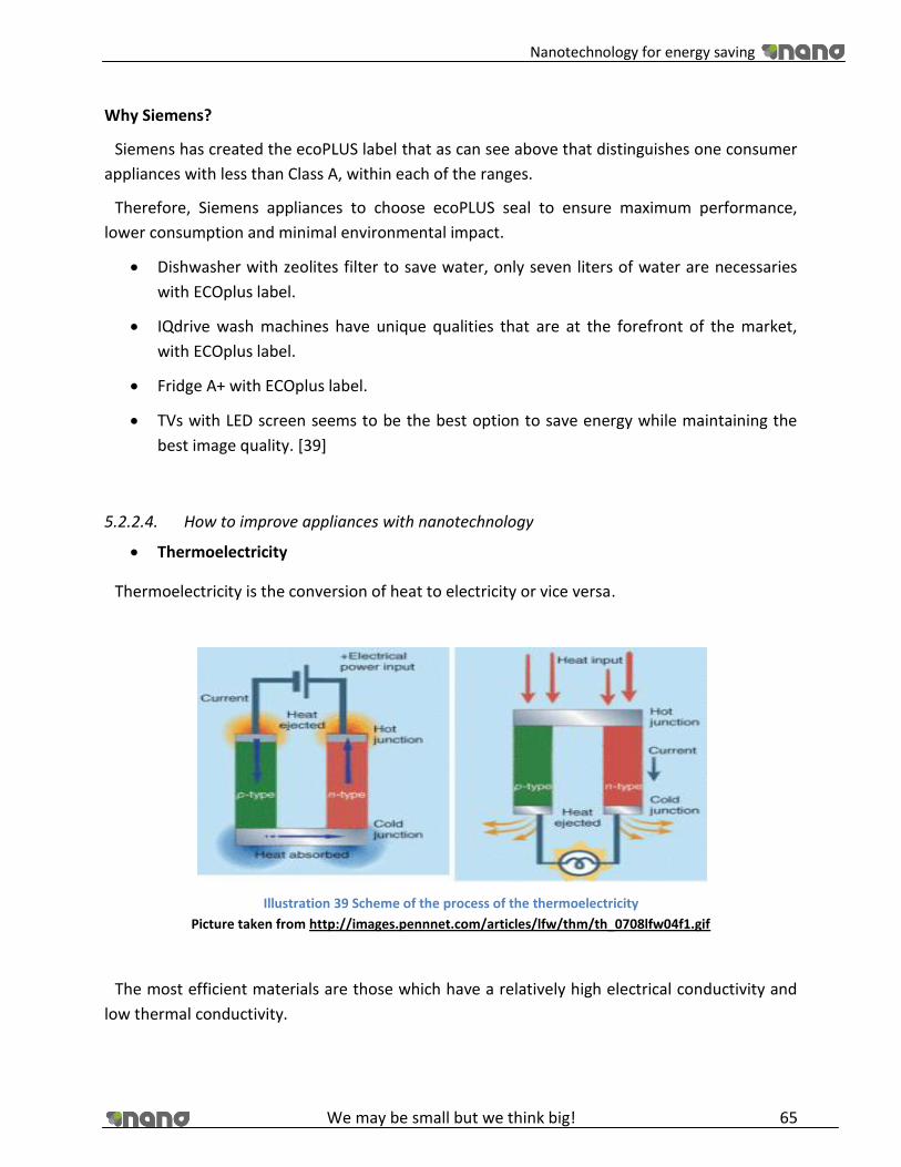
Nanotechnology for energy saving
We may be small but we think big! 65
Why Siemens?
Siemens has created the ecoPLUS label that as can see above that distinguishes one consumer
appliances with less than Class A, within each of the ranges.
Therefore, Siemens appliances to choose ecoPLUS seal to ensure maximum performance,
lower consumption and minimal environmental impact.
Dishwasher with zeolites filter to save water, only seven liters of water are necessaries
with ECOplus label.
IQdrive wash machines have unique qualities that are at the forefront of the market,
with ECOplus label.
Fridge A+ with ECOplus label.
TVs with LED screen seems to be the best option to save energy while maintaining the
best image quality. [39]
5.2.2.4. How to improve appliances with nanotechnology
Thermoelectricity
Thermoelectricity is the conversion of heat to electricity or vice versa.
Illustration 39 Scheme of the process of the thermoelectricity
Picture taken from http://images.pennnet.com/articles/lfw/thm/th_0708lfw04f1.gif
The most efficient materials are those which have a relatively high electrical conductivity and
low thermal conductivity.

Nanotechnology for energy saving
We may be small but we think big! 66
The target of the Thermoelectricity is to increase the efficiency of the electric and electronic
devices, making useful energy from the waste of heat produced by such appliances.
The key to the development will be controlling the dimensionality of new materials to ensure
that thermal conductivity is decreased while at the same time maintaining or increasing
electrical conductivity.
Nanotechnology applied to thermoelectricity:
Nanocrystalline materials: It can aid in decreasing thermal conduction.
Quantum well materials: These effectively confine electric charge to two dimensions.
Superlattices: These have the effect of reducing thermal conduction without affecting
electrical conduction.
Nanowires and Nanoparticles: Could be increased the efficiency and have potential
applications in micro-coolers and micro-generators. [33]
5.2.3. Biogas.
5.2.3.1. Biogas technology.
Biogas is a mixture whose main components are methane and carbon dioxide, which produces
cone result of fermentation of organic matter in the absence of air, by the action of a group of
microorganisms.
In nature there is a wide variety of organic waste from biogas which can be obtained, among
them are: wastes from domestic animals such as cows, pigs and poultry, vegetable waste such
as straw, grass, leaves and household waste.
Biogas is the result of digestion of biomass in anaerobic conditions has a caloric value of about
5,500 kcal/m3.
Biogas in Europe: The European Union countries are becoming more and more interested in
the characteristics of biogas in terms of environment and energy production, developing its
recovery appropriate channels according to their potential. Thus biogas production reached
almost 5.3 million tons of oil equivalent in 2006, which represents a 13.6% increase over 2005.

Nanotechnology for energy saving
We may be small but we think big! 67
Illustration 40 Primary production of biogas in Europe
Map taken from Biopact Toward a green energy pact between Europe and Africa.
5.2.3.2. Biogas installation in a familiar house.
Daily load: 20 Kg of manure (cow) and 60 liters of water mixed.
Biogas production diary: 700-750 liters ( 4 to 5 hours of cooking)
Fertilizer production diary: 80 liters
Retention time: 75 days
Average time delay to start working: 2 months
Temperature: 10 : C
Ambient temperature: -12 to 20 : C.
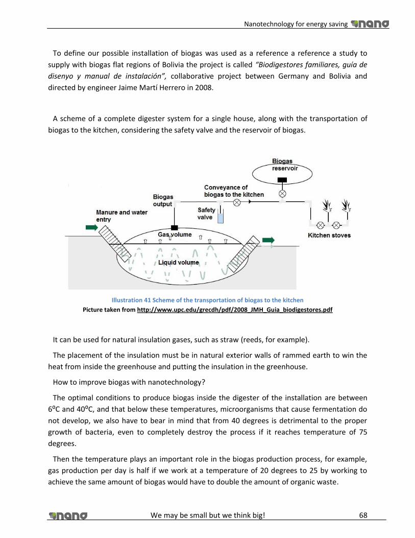
Nanotechnology for energy saving
We may be small but we think big! 68
To define our possible installation of biogas was used as a reference a reference a study to
supply with biogas flat regions of Bolivia the project is called “Biodigestores familiares, guía de
disenyo y manual de instalación”, collaborative project between Germany and Bolivia and
directed by engineer Jaime Martí Herrero in 2008.
A scheme of a complete digester system for a single house, along with the transportation of
biogas to the kitchen, considering the safety valve and the reservoir of biogas.
Illustration 41 Scheme of the transportation of biogas to the kitchen
Picture taken from http://www.upc.edu/grecdh/pdf/2008_JMH_Guia_biodigestores.pdf
It can be used for natural insulation gases, such as straw (reeds, for example).
The placement of the insulation must be in natural exterior walls of rammed earth to win the
heat from inside the greenhouse and putting the insulation in the greenhouse.
How to improve biogas with nanotechnology?
The optimal conditions to produce biogas inside the digester of the installation are between
6:C and 40:C, and that below these temperatures, microorganisms that cause fermentation do
not develop, we also have to bear in mind that from 40 degrees is detrimental to the proper
growth of bacteria, even to completely destroy the process if it reaches temperature of 75
degrees.
Then the temperature plays an important role in the biogas production process, for example,
gas production per day is half if we work at a temperature of 20 degrees to 25 by working to
achieve the same amount of biogas would have to double the amount of organic waste.

Nanotechnology for energy saving
We may be small but we think big! 69
We must take into account that the winter in Poland is very cold, and it is a drawback to
achieve production of biogas, so we need an extra quantity of heat. We will achieve this by
using part of the gas produced to heat water and driven by a small pump through a coil installed
inside the digester. [36], [37], [38]
Here is where nanotechnology could have a very important role:
Illustration 42 Nanomaterials for the construction of a digester
Picture taken from J. Herrero. 2008. Biodigestores : Guía de diseño y de instalación.GTZ-Energía. Bolivia.
In the previous picture you can see the preparation of insulating materials for the construction
of a digester in the Bolivian highlands, where the
variation in temperature can be 30 ° C on the same day,
-5 ° C at night and 25 ° C at noon.
We can see in this picture Biodigestor already installed,
and beginning to be and manure -laden water until their
mouths are plugged
tubes inside and out. The digester house would have a
similar size to the picture; this is a design for a biogas
provides townhouse in Bolivian highlands.
Illustration 43 Digester installed Picture taken from J. Herrero. 2008. Biodigestores : Guía de diseño y de instalación.GTZ-Energía. Bolivia.
Nanotechnology for energy saving
We may be small but we think big! 70
With nanotechnology we can get insulation materials that would be unthinkable a few years
ago.
Thanks to that we can maintain the ideal temperature inside the digester and thereby achieve
high efficiency in biogas production.
Insulating nanomaterials are used to keep the temperature constant in an enclosed space such
as a house or a vessel, either warmer or colder than the surroundings
The basic requirement for thermal insulation is to provide a significant resistance path to the
flow of heat through the insulation material.
To accomplish this, the insulation material must reduce the rate of heat transfer by
conduction, convection, radiation, or any combination of these mechanisms. [34], [35], [36]
Insulating materials can be adapted to any size, shape or surface.
Different materials could be used by this target such as:
1. Aerogels and nanofoams. Low density, highly porous materials and high dielectric
constant , with pores in nanoscale dimensions.
2. Thin films. Photochromic, thermochromic and electrochromic thin films are being
developed.
3. Nanocomposites. Materials containing nanoparticles are being developed.
But in the next point we will explain better the insulation possibilities of the nanomaterials. [33]
5.3. Insulation
Thermal insulation is the technology that deals with the trapping of heat inside a structure
through the use of materials with a favorably low rate of heat transfer. Insulation is one of the
most important areas of a house in terms of energy conservation as no matter how much
energy you convert, and how efficiently you do it, it can be a wasted effort if the insulation is
not carefully fitted and designed. Because of this, insulation was a major focus of our project,
with the aim of:
1. Finding a way of insulating a house without nanotechnology which is an
improvement on conventional insulation.
2. Finding a nano material suitable for insulating our nano house and work out a
way of implementing it.
Nanotechnology for energy saving
We may be small but we think big! 71
For both of these studies we will carry out an efficiency and energy saving calculation, and also
a cost analysis. Firstly though, a brief overview of insulation in buildings will be given, beginning
by looking at the technology from the customer’s point of view. The simplest need of a
homeowner is to be warm and comfortable. This can only be achieved with good insulation. The
second need is to save money, as logic tells us, the more heat we can trap inside our house; the
less money has to be spent producing heat energy as less is needed. Typical materials used for
insulation of houses are, rock wool, polystyrene, urethane foam and vermiculite. These
materials are often inefficient, non environmentally friendly and damaging to humans.
The next part of this report will look at a conventional energy saving house during which these
insulation substances will be looked at in more detail. Then in the feasibility study nano
materials will be looked at to see how they can help save energy through insulation. This is a
relatively new and groundbreaking step for the science of insulation.
Generally insulation can be divided into two main parts. Insulation of walls and pipes is much
different than the insulation of windows due to its transparency. At the beginning let’s focus on
the first type.
Nowadays there are numerous insulating materials available. We can choose from the variety
of Styrofoam, polyurethane, fibreglass or phenolic rigid panel. Using combination of these
materials can provide good insulating conditions. It is even possible to obtain the passive house
– a house that is not using external heat sources. However that type of house usually has quite
bad design (the shape has to be very simple) and enormously also thick walls. Another threat is
the fact that in cold regions of earth building such a house is almost impossible. Nanotechnology
is a great chance to improve that situation.
Using the Uponor OZC we have calculated the heat consumption of our house. We have
assumed the 20 degrees Celsius in our house and standard Styrofoam and fibreglass insulation.
It is situated in Pomaria, and we are using metrological data for Koszalin (metrological station in
Kołobrzeg). The total heat that will be dissipated through our house is 18813 kWh for a whole
year. That energy is needlessly wasted.

Nanotechnology for energy saving
We may be small but we think big! 72
Illustration 44 Graph present percentage of energy wasted in a whole house
This graph present percentage of energy wasted in a whole house. As you can see around 43%
of energy is wasted due to ventilation, 14% to windows and 43% through walls and doors.
5.3.1. How can we improve that situation?
5.3.1.1. Walls and doors.
Currently the most popular insulating materials are Styrofoam and glass wool, whose thermal
resistance is 0,52 and 0,55 [m2C/W] respectively. Styrofoam is a porous material obtained
directly from polystyrene. It is highly flammable, so some sort of Styrofoam contains special
additions. This type of Styrofoam is marked as self-extinguish. Styrofoam also provides some
acoustic insulation. Glass wool is an insulating material composed of fibreglass. [42] [43]
Due to its wool-like structure it is also a good sound insulator.
Illustration 45 Insulating material – fiber glass
Picture taken from
http://upload.ecvv.com/upload/Product/20085/China_Fiber_Glass_Wool20085211742485.jpg
Energy wastage
Ventilation
Walls
Windows
Doors
Roof

Nanotechnology for energy saving
We may be small but we think big! 73
Illustration 46 Insulating material – styrofoam
Picture taken from http://rcreptiles.com/blog/media/styrofoam.jpg
The main advantage of this solution is of relatively low cost and sufficient insulating quality.
However, in order to properly insulate a building you have to apply multiple layers of these
materials which increase the cost of whole building. Another disadvantage is the fact that
Styrofoam and fiberglass are flammable.
Aero gels are having the lowest density of any insulating material. The manufacturing process
replaces the liquid component in gel with a gas. Due to that, we obtain a very light “frozen
smoke” (as the 99.98% of is volume is simply air) In touch it is very similar to the Styrofoam, but
it has better properties. In comparison nanotechnology-enhanced aero gels can reach the
thermal resistance of 1.76 with a perspective of growth in a near future. The calculation shows
that solution can reduce the energy losses on walls and doors by 69% (maintaining the same
layer thickness).
Another important thing is that aero gels are very resistant to fire. Even when the fire starts in
one room, they will keep the cool temperature in other rooms. It will not allow the fire to
escape the room where it started. [44][45]
Illustration 47 Aerogels resistant to fire
Picture taken from http://www.optics.rochester.edu/workgroups/cml/opt307/spr08/matt/aerogel-matches.jpg

Nanotechnology for energy saving
We may be small but we think big! 74
5.3.1.2. Ventilation
In order to save energy in a modern house we can install a heat recovery system. The energy
naturally dissipated through the ventilation now can be recovered and used to heat the
incoming air. Solutions available today, using a counter flow approach can reach efficiency up to
95%. However, these heat recovery systems are quite big and hard to install. The thin heat wires
can be replaced by carbon nanotubes in order to reduce dimensions, and improve efficiency.
[46]
Illustration 48 Ventilation – heat recovery system
Picture taken from http://www.isd.com.pl/obrazki/rekuperator1.jpg
Illustration 49 Ventilation – counterflow heat recovery sytem
Picture taken from http://www.omega-bud.pl/img/klima/rekuperator2.jpg
5.3.1.3. Windows
In regions with a long heating season, windows are one of the biggest gaps in insulations of a
house. Over the previous few years, windows have undergone a technological revolution. It is
now possible to have lower heat loss, less air leakage, and warmer window surfaces that
improve comfort of living. The energy efficient windows consist of many different parts – energy
efficient frames, double or even triple glazing and special gas chambers. Those windows has
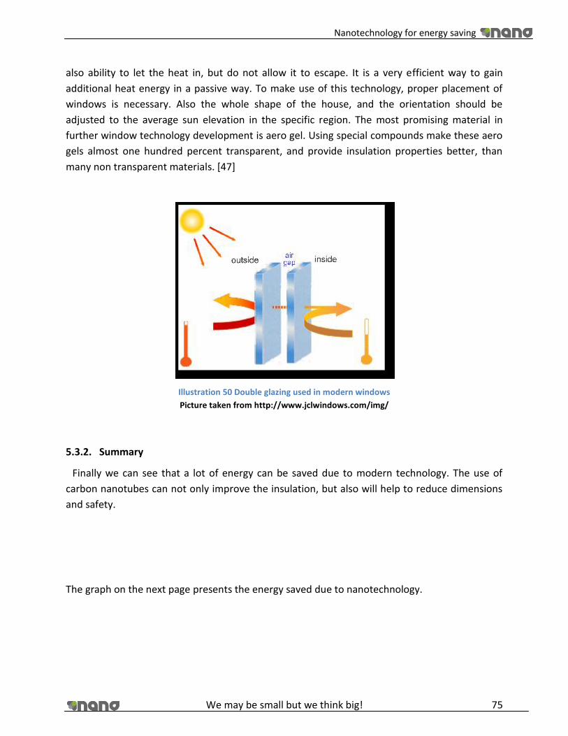
Nanotechnology for energy saving
We may be small but we think big! 75
also ability to let the heat in, but do not allow it to escape. It is a very efficient way to gain
additional heat energy in a passive way. To make use of this technology, proper placement of
windows is necessary. Also the whole shape of the house, and the orientation should be
adjusted to the average sun elevation in the specific region. The most promising material in
further window technology development is aero gel. Using special compounds make these aero
gels almost one hundred percent transparent, and provide insulation properties better, than
many non transparent materials. [47]
Illustration 50 Double glazing used in modern windows
Picture taken from http://www.jclwindows.com/img/
5.3.2. Summary
Finally we can see that a lot of energy can be saved due to modern technology. The use of
carbon nanotubes can not only improve the insulation, but also will help to reduce dimensions
and safety.
The graph on the next page presents the energy saved due to nanotechnology.

Nanotechnology for energy saving
We may be small but we think big! 76
Illustration 51 Graph energy saved due to nanotechnology
As you can see the amount of energy wasted has dropped significantly. We can see that for a
modern house around 69% of energy is saved. For a futuristic house (available approximately in
10 years) it is even better, and around 82% of energy will be saved. We should also keep in
mind, that each year new appliances of nanotechnology are being found. It is very hard to
predict all the possibilities, especially the detailed specification of future products.
Here are some pictures showing our energy consumption study in UPONOR OZC program. [41]
[48] [49]
Table 9 Energy consumption study
Project name: Nano
Localization: Dziwnów
Date: Sunday 30.05.2010, 19:06
Climate zone 3
Surface [m2] 120
Volume [m3] 300
Calculated energy consumption [W] 7883
Energy for ventilation 1592
Energy per square meter 535
Energy per cubic meter 214
Energy consumption per year [kWh/year] 17837
0
2000
4000
6000
8000
10000
12000
14000
16000
18000
20000
Standard House Modern House Futuristic house
Ventilation
Windows
Walls and doors

Nanotechnology for energy saving
We may be small but we think big! 77
Illustration 52 – Yearly summary of energy consumption
Illustration 53 – detailed analysis of energy consumption
Illustration 54 – detailed analysis of energy gains

Nanotechnology for energy saving
We may be small but we think big! 78
5.4. Storage
In a house we want to implement two types of storage devices: batteries and capacitors.
5.4.1. Batteries
Battery is an electrical energy storage device consisting of one or more electrochemical cells. It
stores electricity in chemical energy and it can be converted into electricity. It is characterized
by long charge and discharge time. Thanks to that we have long fairly uniform power supply;
however the power generated by batteries is low in comparison to capacitors.
The first battery was invented in 1800 by Allessandro Volta. Since then batteries have become
very popular and many types were invented. There are two types of batteries. Primary batteries
that can be charge and discharged only once, and secondary batteries that can be charged and
discharged many times. In course of our project we took into consideration only secondary
batteries.
Nowadays, a single cell battery consists of two half cells connected with conductive
electrolyte. One half cell consists of electrolyte and anode, the second one electrolyte and
cathode. Anode is a negative electrode to which negatively charged ions migrate (anions).
Cathode is an opposite to a anode. It is sometimes called a positive electrode. Toward the
cathode positively charged ions (cations) migrate. What triggers the conversion of chemical
energy into electrical energy is a redox reaction. The reduction (addition of electrons) of cations
is present on the cathode, and oxidation (removal of electrons) of ions occurs on anode. The
cathodes are not touching directly each other but are connected electrically by electrolyte. Two
half cells are linked with salt bridge separator that permits the transport of charged molecules
(ions) but not water molecules. The drawing on the other page shows a simple galvanic cell.
Illustration 55 Sample drawing showing the voltaic cell from a battery.
Picture taken from http://en.wikipedia.org/wiki/File:ElectrochemCell.png
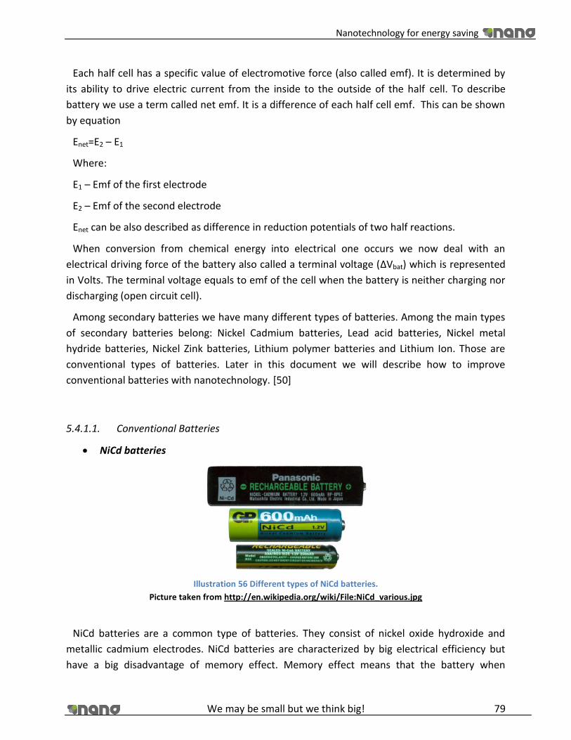
Nanotechnology for energy saving
We may be small but we think big! 79
Each half cell has a specific value of electromotive force (also called emf). It is determined by
its ability to drive electric current from the inside to the outside of the half cell. To describe
battery we use a term called net emf. It is a difference of each half cell emf. This can be shown
by equation
Enet=E2 – E1
Where:
E1 – Emf of the first electrode
E2 – Emf of the second electrode
Enet can be also described as difference in reduction potentials of two half reactions.
When conversion from chemical energy into electrical one occurs we now deal with an
electrical driving force of the battery also called a terminal voltage (ΔVbat) which is represented
in Volts. The terminal voltage equals to emf of the cell when the battery is neither charging nor
discharging (open circuit cell).
Among secondary batteries we have many different types of batteries. Among the main types
of secondary batteries belong: Nickel Cadmium batteries, Lead acid batteries, Nickel metal
hydride batteries, Nickel Zink batteries, Lithium polymer batteries and Lithium Ion. Those are
conventional types of batteries. Later in this document we will describe how to improve
conventional batteries with nanotechnology. [50]
5.4.1.1. Conventional Batteries
NiCd batteries
Illustration 56 Different types of NiCd batteries.
Picture taken from http://en.wikipedia.org/wiki/File:NiCd_various.jpg
NiCd batteries are a common type of batteries. They consist of nickel oxide hydroxide and
metallic cadmium electrodes. NiCd batteries are characterized by big electrical efficiency but
have a big disadvantage of memory effect. Memory effect means that the battery when
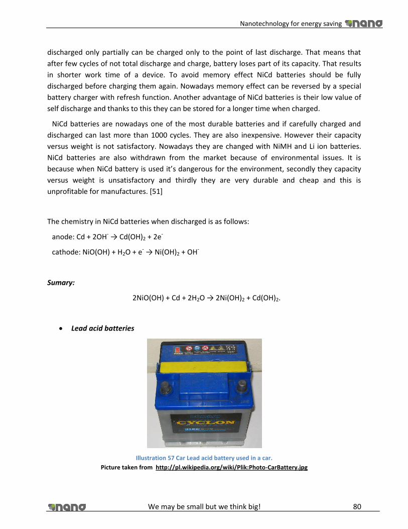
Nanotechnology for energy saving
We may be small but we think big! 80
discharged only partially can be charged only to the point of last discharge. That means that
after few cycles of not total discharge and charge, battery loses part of its capacity. That results
in shorter work time of a device. To avoid memory effect NiCd batteries should be fully
discharged before charging them again. Nowadays memory effect can be reversed by a special
battery charger with refresh function. Another advantage of NiCd batteries is their low value of
self discharge and thanks to this they can be stored for a longer time when charged.
NiCd batteries are nowadays one of the most durable batteries and if carefully charged and
discharged can last more than 1000 cycles. They are also inexpensive. However their capacity
versus weight is not satisfactory. Nowadays they are changed with NiMH and Li ion batteries.
NiCd batteries are also withdrawn from the market because of environmental issues. It is
because when NiCd battery is used it’s dangerous for the environment, secondly they capacity
versus weight is unsatisfactory and thirdly they are very durable and cheap and this is
unprofitable for manufactures. [51]
The chemistry in NiCd batteries when discharged is as follows:
anode: Cd + 2OH- → Cd(OH)2 + 2e-
cathode: NiO(OH) + H2O + e- → Ni(OH)2 + OH-
Sumary:
2NiO(OH) + Cd + 2H2O → 2Ni(OH)2 + Cd(OH)2.
Lead acid batteries
Illustration 57 Car Lead acid battery used in a car.
Picture taken from http://pl.wikipedia.org/wiki/Plik:Photo-CarBattery.jpg

Nanotechnology for energy saving
We may be small but we think big! 81
This type of battery is composed of a galvanic cell consisting of lead electrode (anode) and lead
dioxide electrode (cathode) both submerged in 37% sulphuric acid which act as an electrolyte.
This kind of buttery was discovered in year 1859 and despite its many disadvantages is still one
of the most popular big batteries in the world. It is widely used in car industry. It is also used as
an element of backup power storage system in many industry buildings, hospitals, telephone
centrals and in field lightning systems.
A typical Lead acid battery is built of 6 cells connected in series. Each cell generates an
electromotive energy equal 2.1 V so the whole battery has SEM equal 12.6 V. Thanks to low
internal resistance lead acid battery is able to generate high voltages and that’s why it found use
in car industry.
Among the main disadvantages of lead acid batteries is the fact that when a battery is fully
discharged the PbSO4 that is formed in the electrolyte starts to crystallize after some time.
Crystallized PbSO4 is an electrical insulator. That leads to a drop in capacitance of the battery. To
prevent this manufacturers add sulfur to electrodes that lowers the adhesion of PbSO4 crystals
on electrodes. Another disadvantage of lead acid batteries is that they can lose easily water
when not sealed properly. This leads to concentrating the electrolyte. There is also risk of acid
leaking. Both problems can be solved with good sealing. [52]
The chemistry in lead acid battery when discharged is as follows:
anode: Pb + SO42- ⇌ PbSO4 + 2e-
cathode: PbO2 + SO42- + 4H+ + 2e- ⇌ PbSO4 + 2H2
Sumary:
Pb + PbO2 + 2H2SO42- ⇌ 2 PbSO4 + 2H2.
Nickel Metal Hydride batteries
Illustration 58 Multi-cell nickel metal hydride battery.
Picture taken from http://en.wikipedia.org/wiki/File:Nickel-Metallhydrid-Batterie.jpg
Nanotechnology for energy saving
We may be small but we think big! 82
This is the type of battery where the cathode is constructed from the metallic nickel and the
anode is from metal, which reacts with hydrogen liberated during charging, to form a metal
hydride compound. The electrolyte is alkali and the salt bridge in these batteries is from
polyamide or polyethylene.
Among their main advantages is a high energy density around 0.36 MJ/kg. It also does not
contain an environmentally toxic compound such as Cd, like in NiCd batteries. Besides, the
anode construction NiMH batteries don not differ much from NiCd batteries. Another
advantage of these batteries is that their cell voltage equals 1.2 V so they can be used in
exchange for NiCd batteries. NiMH batteries have also around 3 times bigger capacitance in
comparison to NiCd type. They also have low memory effect.
On the other hand, NiMH batteries are more expensive than the older type with cadmium.
They are also characterized with shorter life (number of charge/discharge cycles). Also they
have short time of self discharge.
It took a fairly long time to introduce NiMH batteries into the market. That was because the
cell needs absolute sealing, a porous electrode and a high pressure. The only solution was to
bind Hydrogen into chemical compound that will be formed during charging. This compound has
to decay during discharging to release hydrogen molecules. Such compounds were discovered
at the end o the 1960. In modern NiMH batteries anodes are constructed from metallic alloys.
Those alloys consist of metals such as vanadium, titanium, zircon, nickel, chromium, cobalt and
iron. Why such alloys have better efficiency (binging and releasing hydrogen) is still unknown,
the proportions of alloys are established experimentally. [53]
The chemistry in NiMH battery when discharged is as follows:
anode: H2O + M + e- ⇌ OH- + MH
cathode: Ni(OH)2 + OH- ⇌ NiO(OH) + H2O + e-
Sumary:
M + Ni(OH)2 ⇌ NiO(OH) + MH.
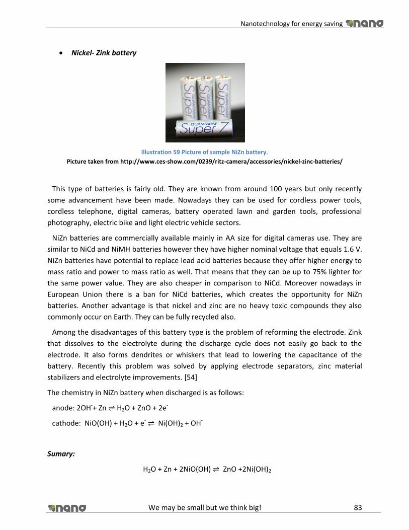
Nanotechnology for energy saving
We may be small but we think big! 83
Nickel- Zink battery
Illustration 59 Picture of sample NiZn battery.
Picture taken from http://www.ces-show.com/0239/ritz-camera/accessories/nickel-zinc-batteries/
This type of batteries is fairly old. They are known from around 100 years but only recently
some advancement have been made. Nowadays they can be used for cordless power tools,
cordless telephone, digital cameras, battery operated lawn and garden tools, professional
photography, electric bike and light electric vehicle sectors.
NiZn batteries are commercially available mainly in AA size for digital cameras use. They are
similar to NiCd and NiMH batteries however they have higher nominal voltage that equals 1.6 V.
NiZn batteries have potential to replace lead acid batteries because they offer higher energy to
mass ratio and power to mass ratio as well. That means that they can be up to 75% lighter for
the same power value. They are also cheaper in comparison to NiCd. Moreover nowadays in
European Union there is a ban for NiCd batteries, which creates the opportunity for NiZn
batteries. Another advantage is that nickel and zinc are no heavy toxic compounds they also
commonly occur on Earth. They can be fully recycled also.
Among the disadvantages of this battery type is the problem of reforming the electrode. Zink
that dissolves to the electrolyte during the discharge cycle does not easily go back to the
electrode. It also forms dendrites or whiskers that lead to lowering the capacitance of the
battery. Recently this problem was solved by applying electrode separators, zinc material
stabilizers and electrolyte improvements. [54]
The chemistry in NiZn battery when discharged is as follows:
anode: 2OH-+ Zn ⇌ H2O + ZnO + 2e-
cathode: NiO(OH) + H2O + e- ⇌ Ni(OH)2 + OH-
Sumary:
H2O + Zn + 2NiO(OH) ⇌ ZnO +2Ni(OH)2

Nanotechnology for energy saving
We may be small but we think big! 84
Lithium Ion batteries
Illustration 60 Picture of a Multi-cell Lithium Ion battery.
Picture taken from http://pl.wikipedia.org/w/index.php?title=Plik:Lithium-Ionen-
Accumulator.jpg&filetimestamp=20080115024209
In this type of battery one electrode is composed of porous carbon and the other one from
metal alloys. The electrolyte is made of complex lithium salts such as LiPF6, LiBF4 or LiClO4 in
an organic solvent, such as ethylene carbonate. This type of battery has nominal voltage equal
to 3.6 V per cell. That means that two times bigger energy can be stored per the same weight in
comparison to NiMH batteries. There is also no memory or lazy battery effect. This is a big
advantage of these batteries.
Li ion batteries are very popular in consumer electronics, such as laptops, cell phones or digital
cameras. They are also being applied in electrical vehicles and energy storage in backup
systems. Their advantage is a slow loss of charge when stored properly.
Among the advantages of Li ion batteries are a wide variety of shapes and sizes old batteries
that are efficiently fitting the consumers electronics. They are also lighter than other secondary
type batteries. Li ion batteries are also characterized by low self discharge rate (around 5- 10%
per month comparing with 30% of NiMH batteries)
But there are also disadvantages of Li ion batteries. Storing fully charged batteries at higher
temperatures may lead to big irreversible energy losses (25 °C during a year may lead to 20%
capacitance loss). These losses can be lowered up to 2% capacity loss by storing the batteries
charged only in 40% – 60%. Li ion batteries are also characterized by bigger internal resistance in
comparison to NiCd or NiMH batteries. This value increases with both cycling and age. Also Li
ion batteries are not so durable as NiMH batteries and can be dangerous (explosive) when
treated improperly. When overcharged and overheated they can be irreversibly damaged.
Those problems are solved by installing small circuits that will cut off the battery when its
capacitance reaches nominal value.

Nanotechnology for energy saving
We may be small but we think big! 85
In Li ion batteries lithium ions are transported from and to cathode or anode. This is
accompanied by the transition of metal, cobalt, in LixCoO2 being oxidized from
Co3+ to Co4+ during charging. [55]
There are different types of anodes and cathodes used in Li ion batteries. Below are the tables
from Wikipedia (http://en.wikipedia.org/wiki/Lithium-ion_battery#Cathodes and
http://en.wikipedia.org/wiki/Lithium-ion_battery#Anodes) presenting different composition of
anodes and cathode.
Table 10 Different types of anodes and cathodes used in Li ion batteries.
Below are the tables from Wikipedia (http://en.wikipedia.org/wiki/Lithium-ion_battery#Cathodes and
http://en.wikipedia.org/wiki/Lithium-ion_battery#Anodes)
ANODES CATHODES
Cathode Material Average Voltage Anode Material Average Voltage
LiCoO2 3.7 V Graphite (LiC6) 0.1-0.2 V
LiMn2O4 4.0 V Hard Carbon (LiC6}) ? V
LiNiO2 3.5 V Titanate (Li4Ti5O12}) 1-2 V
LiFePO4 3.3 V Si (Li4.4Si) 0.5-1 V
Li2FePO4F 3.6 V Li|4.4|Ge) 0.7-1.2 V
LiCo1/3Ni1/3Mn1/3O2 3.6 V
Li(LiaNixMnyCoz)O2 4.2 V
The chemistry in Lion battery when discharged is as follows (x is a coefficient, in this equations
unit moles are used):
anode: xLi+ + xe- + 6C ⇌ LixC6
cathode: LiCoO2 ⇌ Li1-xCoO2 + xLi+ + xe-
Sumary:
Li+ + LiCoO2 ⇌ Li2O + CoO
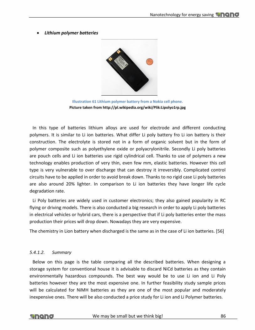
Nanotechnology for energy saving
We may be small but we think big! 86
Lithium polymer batteries
Illustration 61 Lithium polymer battery from a Nokia cell phone.
Picture taken from http://pl.wikipedia.org/wiki/Plik:Lipolyo1rp.jpg
In this type of batteries lithium alloys are used for electrode and different conducting
polymers. It is similar to Li ion batteries. What differ Li poly battery fro Li ion battery is their
construction. The electrolyte is stored not in a form of organic solvent but in the form of
polymer composite such as polyethylene oxide or polyacrylonitrile. Secondly Li poly batteries
are pouch cells and Li ion batteries use rigid cylindrical cell. Thanks to use of polymers a new
technology enables production of very thin, even few mm, elastic batteries. However this cell
type is very vulnerable to over discharge that can destroy it irreversibly. Complicated control
circuits have to be applied in order to avoid break down. Thanks to no rigid case Li poly batteries
are also around 20% lighter. In comparison to Li ion batteries they have longer life cycle
degradation rate.
Li Poly batteries are widely used in customer electronics; they also gained popularity in RC
flying or driving models. There is also conducted a big research in order to apply Li poly batteries
in electrical vehicles or hybrid cars, there is a perspective that if Li poly batteries enter the mass
production their prices will drop down. Nowadays they are very expensive.
The chemistry in Lion battery when discharged is the same as in the case of Li ion batteries. [56]
5.4.1.2. Summary
Below on this page is the table comparing all the described batteries. When designing a
storage system for conventional house it is advisable to discard NiCd batteries as they contain
environmentally hazardous compounds. The best way would be to use Li ion and Li Poly
batteries however they are the most expensive one. In further feasibility study sample prices
will be calculated for NiMH batteries as they are one of the most popular and moderately
inexpensive ones. There will be also conducted a price study for Li ion and Li Polymer batteries.
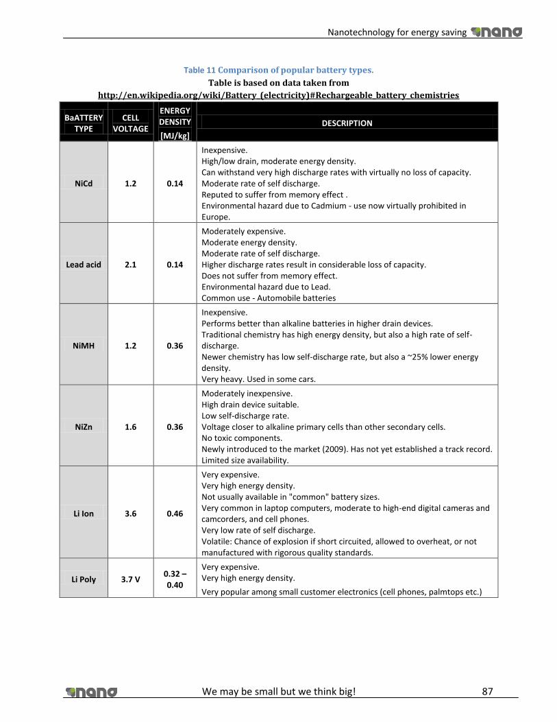
Nanotechnology for energy saving
We may be small but we think big! 87
Table 11 Comparison of popular battery types.
Table is based on data taken from
http://en.wikipedia.org/wiki/Battery_(electricity)#Rechargeable_battery_chemistries
BaATTERY TYPE
CELL VOLTAGE
ENERGY DENSITY
[MJ/kg]
DESCRIPTION
NiCd 1.2 0.14
Inexpensive. High/low drain, moderate energy density. Can withstand very high discharge rates with virtually no loss of capacity. Moderate rate of self discharge. Reputed to suffer from memory effect . Environmental hazard due to Cadmium - use now virtually prohibited in Europe.
Lead acid 2.1 0.14
Moderately expensive. Moderate energy density. Moderate rate of self discharge. Higher discharge rates result in considerable loss of capacity. Does not suffer from memory effect. Environmental hazard due to Lead. Common use - Automobile batteries
NiMH 1.2 0.36
Inexpensive. Performs better than alkaline batteries in higher drain devices. Traditional chemistry has high energy density, but also a high rate of self-discharge. Newer chemistry has low self-discharge rate, but also a ~25% lower energy density. Very heavy. Used in some cars.
NiZn 1.6 0.36
Moderately inexpensive. High drain device suitable. Low self-discharge rate. Voltage closer to alkaline primary cells than other secondary cells. No toxic components. Newly introduced to the market (2009). Has not yet established a track record. Limited size availability.
Li Ion 3.6 0.46
Very expensive. Very high energy density. Not usually available in "common" battery sizes. Very common in laptop computers, moderate to high-end digital cameras and camcorders, and cell phones. Very low rate of self discharge. Volatile: Chance of explosion if short circuited, allowed to overheat, or not manufactured with rigorous quality standards.
Li Poly 3.7 V 0.32 – 0.40
Very expensive. Very high energy density.
Very popular among small customer electronics (cell phones, palmtops etc.)

Nanotechnology for energy saving
We may be small but we think big! 88
5.4.1.3. Possible improvement of batteries with application of nanotechnology
Taking into consideration the battery design there is not much to be changed and improved.
We should focus on improvement of battery components. These are electrodes and electrolyte.
The goal is to increase the power density of batteries, their nominal voltage as well as their
durability and life cycle.
Electrolyte Improvement
Improving electrolyte is not a popular approach to make batteries better, however, there are
some researches done in order to do this. Li poly batteries are taken into account mainly.
Scientists are working on improving the composition of polymer electrolyte. According to the
information found via The Electrochemical society there are prospects of improving the battery
performance by dispersion of nano inorganic particles of TiO2, Al2O3, MgO. This leads to one,
two or even three fold improvement of battery conductivity. In a short review “Transport
studies on nano-composite solid polymer electrolyte for lithiumbatteries” by C.W. Lin, C L.
Hung and B. J. Hwang we can read:
“The impedance results showed that the addition of 5%TiO2 nano-size
particle to the polymer matrix improves the conductivity (1.34 x 0-4 S/cm) by
an order of magnitude at room temperature.”*57+*63+
Moreover, according to “electrochemical properties of nano filler added PEO solid
electrolyte” by Kwang-Sun Ji, Hee-Soo Moon, Jong-Wook Kim, Jong-Wan Park, the addition of
SiO2 to PEO-LiClO4 based electrolyte increased conductivity by 2~3 orders of magnitude from
10-8S/cm to 2.4 x 10⁻⁶S/cm at room temperature.[58]
There is also an experiment carried out where instead of the addition of the earlier mentioned
inorganic nano particles, Zirconium based Super-acid nano particles will be added. Scientists
report that this results in an increase of the value of the lithium transference number together
with overall good transport and stability properties. [59][62]
Electrode improvement
In this area there are many possibilities of improvement. Starting from carbon nanotubes, and
even more effective new silicon nanotubes, to nanocomposite electrodes. All this things are
now in development, on the internet there are many interesting ideas described. Here we will
tell briefly about carbon and silicon nanotubes and few examples of nanocomposite electrodes.
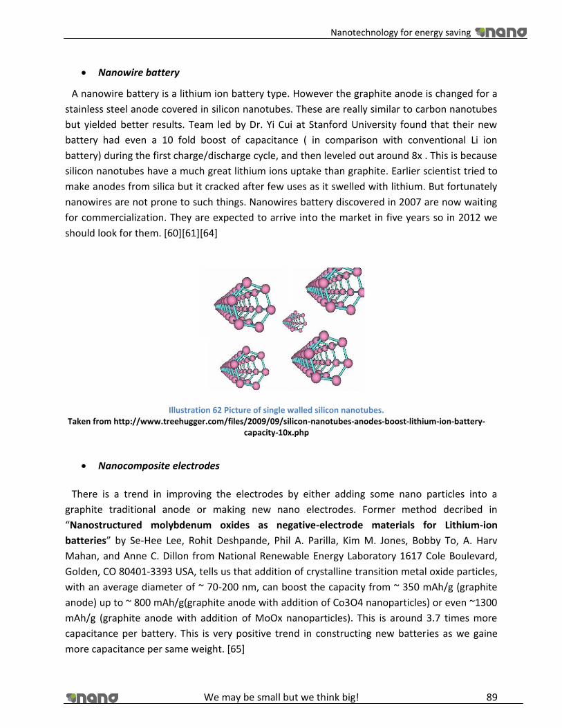
Nanotechnology for energy saving
We may be small but we think big! 89
Nanowire battery
A nanowire battery is a lithium ion battery type. However the graphite anode is changed for a
stainless steel anode covered in silicon nanotubes. These are really similar to carbon nanotubes
but yielded better results. Team led by Dr. Yi Cui at Stanford University found that their new
battery had even a 10 fold boost of capacitance ( in comparison with conventional Li ion
battery) during the first charge/discharge cycle, and then leveled out around 8x . This is because
silicon nanotubes have a much great lithium ions uptake than graphite. Earlier scientist tried to
make anodes from silica but it cracked after few uses as it swelled with lithium. But fortunately
nanowires are not prone to such things. Nanowires battery discovered in 2007 are now waiting
for commercialization. They are expected to arrive into the market in five years so in 2012 we
should look for them. [60][61][64]
Nanocomposite electrodes
There is a trend in improving the electrodes by either adding some nano particles into a
graphite traditional anode or making new nano electrodes. Former method decribed in
“Nanostructured molybdenum oxides as negative-electrode materials for Lithium-ion
batteries” by Se-Hee Lee, Rohit Deshpande, Phil A. Parilla, Kim M. Jones, Bobby To, A. Harv
Mahan, and Anne C. Dillon from National Renewable Energy Laboratory 1617 Cole Boulevard,
Golden, CO 80401-3393 USA, tells us that addition of crystalline transition metal oxide particles,
with an average diameter of ~ 70-200 nm, can boost the capacity from ~ 350 mAh/g (graphite
anode) up to ~ 800 mAh/g(graphite anode with addition of Co3O4 nanoparticles) or even ~1300
mAh/g (graphite anode with addition of MoOx nanoparticles). This is around 3.7 times more
capacitance per battery. This is very positive trend in constructing new batteries as we gaine
more capacitance per same weight. [65]
Illustration 62 Picture of single walled silicon nanotubes. Taken from http://www.treehugger.com/files/2009/09/silicon-nanotubes-anodes-boost-lithium-ion-battery-
capacity-10x.php
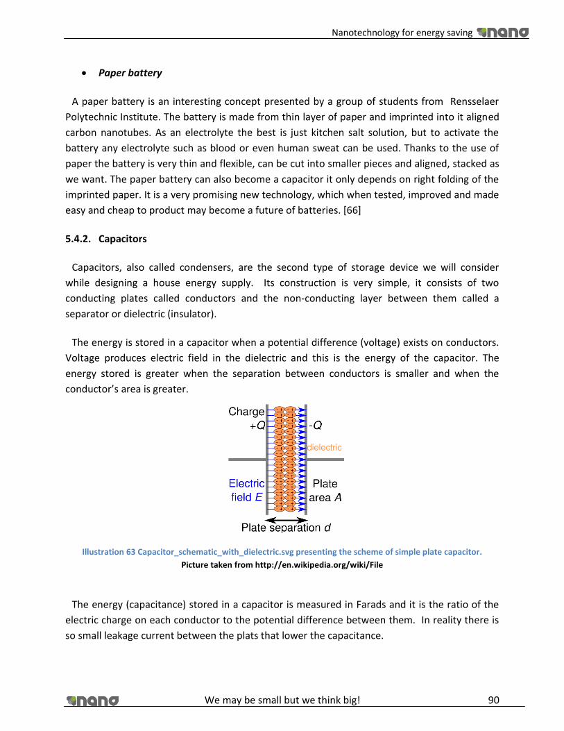
Nanotechnology for energy saving
We may be small but we think big! 90
Paper battery
A paper battery is an interesting concept presented by a group of students from Rensselaer
Polytechnic Institute. The battery is made from thin layer of paper and imprinted into it aligned
carbon nanotubes. As an electrolyte the best is just kitchen salt solution, but to activate the
battery any electrolyte such as blood or even human sweat can be used. Thanks to the use of
paper the battery is very thin and flexible, can be cut into smaller pieces and aligned, stacked as
we want. The paper battery can also become a capacitor it only depends on right folding of the
imprinted paper. It is a very promising new technology, which when tested, improved and made
easy and cheap to product may become a future of batteries. [66]
5.4.2. Capacitors
Capacitors, also called condensers, are the second type of storage device we will consider
while designing a house energy supply. Its construction is very simple, it consists of two
conducting plates called conductors and the non-conducting layer between them called a
separator or dielectric (insulator).
The energy is stored in a capacitor when a potential difference (voltage) exists on conductors.
Voltage produces electric field in the dielectric and this is the energy of the capacitor. The
energy stored is greater when the separation between conductors is smaller and when the
conductor’s area is greater.
Illustration 63 Capacitor_schematic_with_dielectric.svg presenting the scheme of simple plate capacitor.
Picture taken from http://en.wikipedia.org/wiki/File
The energy (capacitance) stored in a capacitor is measured in Farads and it is the ratio of the
electric charge on each conductor to the potential difference between them. In reality there is
so small leakage current between the plats that lower the capacitance.

Nanotechnology for energy saving
We may be small but we think big! 91
Nowadays capacitors are used widely in electronic circuits to block direct current (DC) while
allowing the alternative current (AC) to pass. They are also used to smoothen the circuit a filter
the interferences.
What differentiates capacitors from batteries, as we consider them energy storage devices, is
that capacitors are able to supply a large amount of voltage however in short time. That is why
it is hard to use them as a long term power supply, however there is a great use for them when
the burst of energy is necessary. For example in a electric car engine, or in a house to open the
garage door or to start the work of fridge compressor.
Among capacitors there are many different types of them differing in materials they are made
from. Some of them are electrolytic capacitors, tantalum capacitors, ceramic capacitors,
polystyrene capacitors, polyester and polypropylene capacitors, mica capacitors. The more
modern ones are ultracapacitors also called electric double layer capacitors. Later in this
document we will also propose how to improve capacitors with use of nanotechnology. [67]
Electrolytic capacitors
Illustration 64 Picture of different types of electrolytic capacitors
Picture taken from
http://pl.wikipedia.org/w/index.php?title=Plik:Electrolytic_capacitors.jpg&filetimestamp=20060610061608
These types of capacitors are constructed from two pieces of conducting aluminum foils,
where one is coated with an insulating oxide layer, and a paper spacer soaked in electrolyte
(The electrolyte is usually boric acid or sodium borate in aqueous solution). The layer which is
insulated by the oxide layer is the anode while the liquid electrolyte and the second foil acts as
the cathode. The whole construction is then rolled and put in an aluminum case. Thanks to the
use of electrolyte there is an increase of capacitance per unit volume. These types of capacitors
are characterized by large values of capacitance (up to 1000µF) in comparison with the size of
the capacitor. It is so because a dielectric layer is very thin. The most important characteristic of

Nanotechnology for energy saving
We may be small but we think big! 92
electrolyte capacitors is that they are polarized. They have a positive and negative electrode.
Electrolyte capacitors are mainly used as a ripple filter in a power supply circuit, or as a filter to
bypass low frequency signals.
Another type of electrolytic capacitor is a tantalum capacitor. This one use a material called
tantalum as electrodes. Tantalum capacitors are manufactured from a powder of relatively pure
tantalum metal. The typical particle size is between 2 and 10 μm thus the surface area is
increased. That leads to increase of capacitance. This type of capacitors is also characterized
with big capacitance versus the small size. They are a little more expensive than aluminum
electrolyte capacitors. [68][69]
Polymer capacitors
This is a big group of capacitors that uses different kind of polymers as a dielectric. Among
them Polystyrene Film Capacitors, Polyester Film Capacitors, Polypropylene Capacitors,
Metalized Polyester Film Capacitors can be found. All of them are used in case of low and
medium frequency circuits. Their capacitance is in the range of pikofarads. They are also cheap.
[69]
Illustration 65 Picture representing some of the Polyester Film Capacitors.
Picture taken from http://hobby_elec.piclist.com/e_capa.htm.

Nanotechnology for energy saving
We may be small but we think big! 93
Ceramic capacitors
Illustration 66 Picture of ceramic capacitor
Picture taken from http://hobby_elec.piclist.com/e_capa.htm.
These types of capacitors are constructed with materials such as barium titanate or other
titanium compounds used as the dielectric. Internally, these capacitors are not constructed as a
coil, so they can be used in high frequency applications. Typically, they are used in circuits which
transmit high frequency signals to ground. Their capacitance is very small in the range of
pikofarads. [69]
Ultra capacitors
Ultracapacitors, also called Electric double-layer capacitors, are the most promising however
very expensive type of capacitors. They are characterized by very high capacitance in the range
of few thousand of Farads. This type of capacitor is slightly different in construction than a
traditional one. It consists of two conducting plates but it does not have a typical dielectric
inside. It has two plates separated by intervening substance. This double layer is made from the
same material and it is usually an activated charcoal. Despite the very thin separation between
Illustration 67 Picture showing different types of ultracapacitors Picture taken from http// en.wikipedia.org/wiki/File:Maxwell_MC_and_BC_ultracapacitor_cells_and_modules.jpg

Nanotechnology for energy saving
We may be small but we think big! 94
two plates and thanks to high porosity of activated charcoal the energy stored in each plate is
very great. However the energy released by single cell is of rather low voltage. Multi cell
capacitors have to be used to acquire higher voltage. Another advantage of this kind of
capacitor is its long life- they can stand thousands of cycles, they are also of low toxicity.
Ultracapacitors are also very quick to charge (almost instantly) there is also no fear of
overcharge of the capacitor. All this advantages make them very suitable for future use in
electric car vehicles (for burst of energy during starting the engine) or small consumer
electronics (for example a flash light in cameras). [70]
Illustration 68 Picture showing how energy is stored in the double layer capacitor.
Picture taken from http://en.wikipedia.org/wiki/File:Supercapacitor_diagram.svg
5.4.2.1. Possible improvement Capacitors with application of nanotechnology
The current and future improvements are made to the ultracapacitor type. Nowadays they use
activated charcoal but scientists are already experimenting with replacing them with nanotubes
because of their greater ability to store the energy thanks to high surface area and porosity.
Illustration 69 Picture presenting how the energy is stored between carbon nanotubes in supercapacitor.
Picture taken from http://lees.mit.edu/lees/posters/RU13_Oct05.pdf

Nanotechnology for energy saving
We may be small but we think big! 95
Scientists at the Massachusetts Institute of Technology (MIT) are currently developing a new
technology awaiting commercialization. They claim that a new supercapacitor with carbon
nanotubes has the strength of today's batteries with the longevity and speed of capacitors. This
new technology is very promising for electric car vehicles as well for small electronics that need
instant power, have to charge quickly and be very durable. The table below shows a comparison
between a nanotube ultracapacitor, a conventional ultracapacitor and a typical Li ion battery.
[71][72]
Table 12 Performance comparison of conventional and nanotube capacitors with Li ion battery.
Table taken from http://lees.mit.edu/lees/posters/RU13_Oct05.pdf.
DOUBLE LAYER
CAPACITOR
(typical)
Li ion
BATTERY
(typical)
MIT NANOTUBE ULTRA
CAPACITOR (expected
performance)
Energy density (Wh/kg) 5.44 140 30 - 80
Power density (kW/kg) 5.61 0.2 40
Rated voltage 2.7 2.2 3.5 - 4
Longevity (cycles) 300 000 300 - 1000 300 000
Robustness and reliability Excellent Good Exellent
Temperature dependency Minimal Moderate to
high Minimal
6. Feasibility Study for a nano energy saving house
6.1. Generation
6.1.1. Fuel cells:
For a 1.5A circuit which is the same as the one is our house we need 0.037604 x 1.5 = 0.056406
g per hour.
These fuel cells cost $5000 for a 25W cell, so in our house it makes sense that we use them to
power appliances such as the fridge, TV and laptop. If we buy 4 of these that gives us a total cost
of $20,000.
Because the technology is still developing, it is impossible to even estimate the cost of a nano
fuel cell. This information will not be available for around 5 years although some production in
the automotive industry has begun.

Nanotechnology for energy saving
We may be small but we think big! 96
6.1.2. Solar cells
Conventional House
Solar panels:
We need 12 panels for our roof so 12x794.53= €9,534.35
The installation fee is between €3,611.51 and €24,077, we will assume €13,242.35 for our study
=€22,804.97
A voltage regulator also has to be purchased to accompany the solar cells. These cost €96.35
Total cost =€22,871.95
Nano House
Solar Panels:
I panel x nº of panels= 7.29 x 6 panels= 43.74 A..........50 A
It was very difficult to find cost information on solar nanotechnology as it is only just coming on
to the market, but some websites gave us a little cost information. The expected market price
for quantum dot solar panels will be $1 per Watt, so for our 3801.05 W total power needs, the
total cost of our panels will be $3801.5.
Plus an installation fee of $2000 which is typical for nano solar panels, we have a total cost of
$5801 for our panels.
6.1.3. Wind turbine
Calculations
The total daily consumption of electricity in a conventional house of a family of four members is:
Appliances: 22.2536 kWh daily
Illumination: 1.334 kWh daily
Control center consumption: 7.2 kWh daily
Total: 30.7876 kWh daily
Total consumption per year of electricity in a conventional house of a family of four members is:
30.7876 kWh daily x 365 days = 11,237 kWh per year
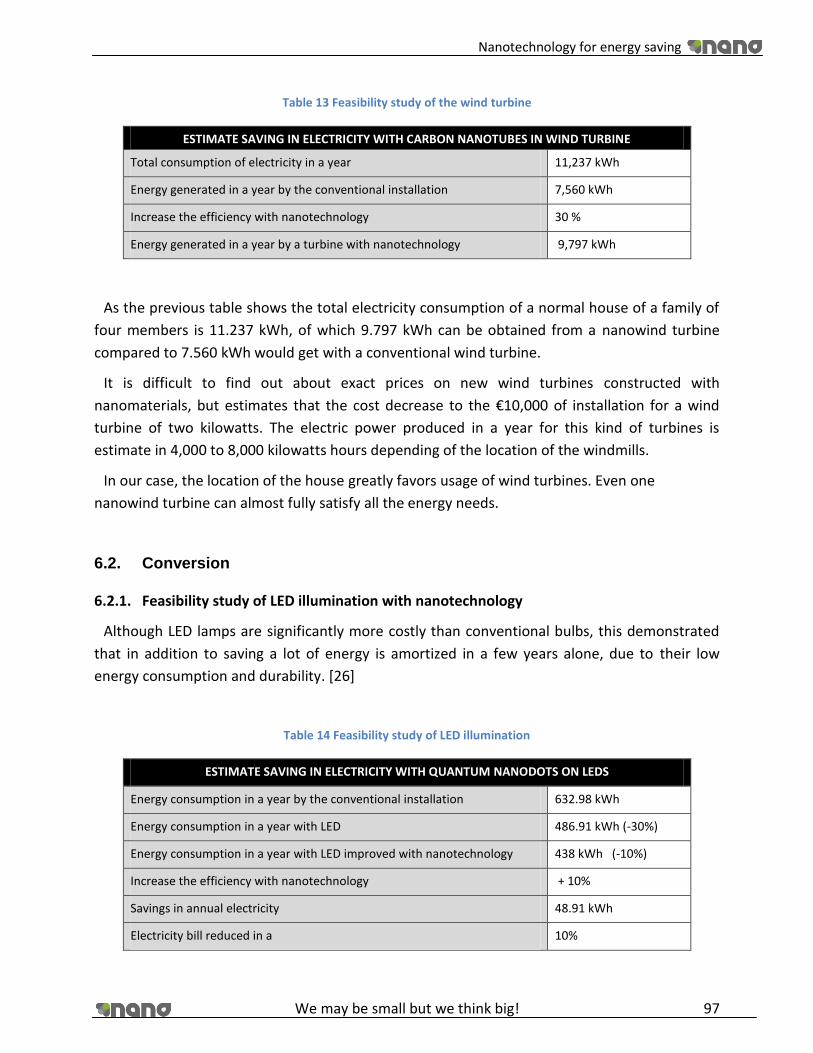
Nanotechnology for energy saving
We may be small but we think big! 97
Table 13 Feasibility study of the wind turbine
ESTIMATE SAVING IN ELECTRICITY WITH CARBON NANOTUBES IN WIND TURBINE
Total consumption of electricity in a year 11,237 kWh
Energy generated in a year by the conventional installation 7,560 kWh
Increase the efficiency with nanotechnology 30 %
Energy generated in a year by a turbine with nanotechnology 9,797 kWh
As the previous table shows the total electricity consumption of a normal house of a family of
four members is 11.237 kWh, of which 9.797 kWh can be obtained from a nanowind turbine
compared to 7.560 kWh would get with a conventional wind turbine.
It is difficult to find out about exact prices on new wind turbines constructed with
nanomaterials, but estimates that the cost decrease to the €10,000 of installation for a wind
turbine of two kilowatts. The electric power produced in a year for this kind of turbines is
estimate in 4,000 to 8,000 kilowatts hours depending of the location of the windmills.
In our case, the location of the house greatly favors usage of wind turbines. Even one
nanowind turbine can almost fully satisfy all the energy needs.
6.2. Conversion
6.2.1. Feasibility study of LED illumination with nanotechnology
Although LED lamps are significantly more costly than conventional bulbs, this demonstrated
that in addition to saving a lot of energy is amortized in a few years alone, due to their low
energy consumption and durability. [26]
Table 14 Feasibility study of LED illumination
ESTIMATE SAVING IN ELECTRICITY WITH QUANTUM NANODOTS ON LEDS
Energy consumption in a year by the conventional installation 632.98 kWh
Energy consumption in a year with LED 486.91 kWh (-30%)
Energy consumption in a year with LED improved with nanotechnology 438 kWh (-10%)
Increase the efficiency with nanotechnology + 10%
Savings in annual electricity 48.91 kWh
Electricity bill reduced in a 10%
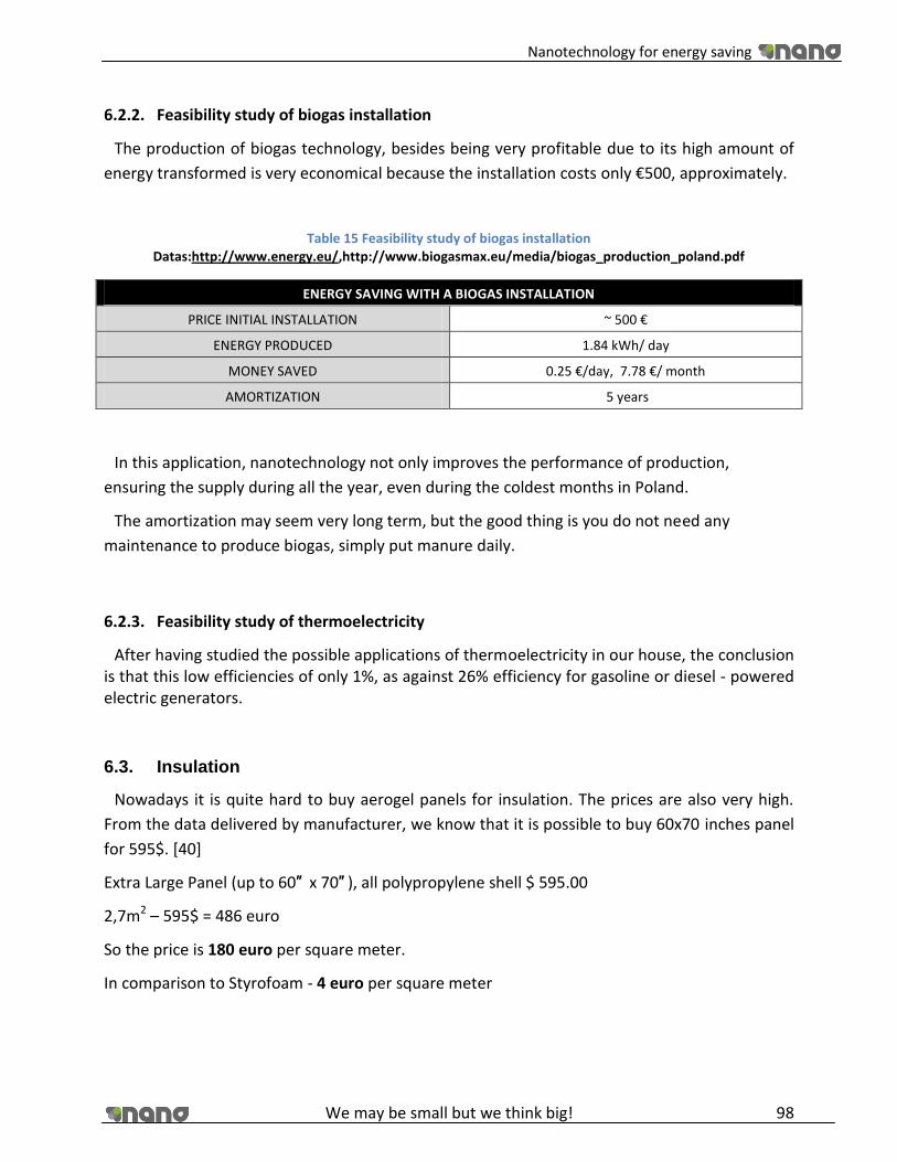
Nanotechnology for energy saving
We may be small but we think big! 98
6.2.2. Feasibility study of biogas installation
The production of biogas technology, besides being very profitable due to its high amount of
energy transformed is very economical because the installation costs only €500, approximately.
Table 15 Feasibility study of biogas installation Datas:http://www.energy.eu/,http://www.biogasmax.eu/media/biogas_production_poland.pdf
ENERGY SAVING WITH A BIOGAS INSTALLATION
PRICE INITIAL INSTALLATION ~ 500 €
ENERGY PRODUCED 1.84 kWh/ day
MONEY SAVED 0.25 €/day, 7.78 €/ month
AMORTIZATION 5 years
In this application, nanotechnology not only improves the performance of production,
ensuring the supply during all the year, even during the coldest months in Poland.
The amortization may seem very long term, but the good thing is you do not need any
maintenance to produce biogas, simply put manure daily.
6.2.3. Feasibility study of thermoelectricity
After having studied the possible applications of thermoelectricity in our house, the conclusion is that this low efficiencies of only 1%, as against 26% efficiency for gasoline or diesel - powered electric generators.
6.3. Insulation
Nowadays it is quite hard to buy aerogel panels for insulation. The prices are also very high.
From the data delivered by manufacturer, we know that it is possible to buy 60x70 inches panel
for 595$. [40]
Extra Large Panel (up to 60″ x 70″ ), all polypropylene shell $ 595.00
2,7m2 – 595$ = 486 euro
So the price is 180 euro per square meter.
In comparison to Styrofoam - 4 euro per square meter

Nanotechnology for energy saving
We may be small but we think big! 99
Even, when we calculate, that aero panels are 3 times better than Styrofoam, we can clearly
see that aerogel is 15 times more expensive than standard solution.
Illustration 70 Insulation prices
We should keep in mind, that insulation of the building requires a lot of resources.
Nanotechnology nowadays is too expensive for that purpose. However, it is expected that the
prices will drop significantly during next 10 years. It is crucial, because now it is chipper to place
3 layers of Styrofoam, and the effect will be almost the same. That makes us think, that aerogel
insulation is still a technology of future, and nowadays it is only useful for advanced
technologies such as space ships and aircrafts – where the mass and properties are much more
important, than the cost of material.
6.4. Storage
6.4.1. Batteries and supercapacitors
During the course of the project we established the power consumption for our house. We
designed the house and decided what appliances we need in a house. These are listed in the
tables in the next page.
0
10
20
30
40
50
60
70
Insulation prices
Styrofoam
Aerogels panels

Nanotechnology for energy saving
We may be small but we think big! 100
Table 16 Appliances in a house, their average time of use per day and daily power consumption
DEVICE TIME OF USE (h) kWh - DAILY
Refrigerator (average - cooling+compresor) 24 3,84
Dishwasher that heats water 3h 3 10,8
Big TV (50-56" DLP television) 6h 6 1,02
DVD + Sound System 3h 3 2,1
Small TV(19" CRT television) 3h 3 0,27
PC average (Desktop Computer & 17" CRT monitor) 6h 6 1,8
Laptop 6h 6 0,27
Microwave 15 min 0,25 0,36
Coffe maker 15 min 0,25 0,225
Toaster 10 min 0,17 0,1224
blender 5 min 0,08 0,048
Iron 30 min 0,5 0,6
Hair dryer 20 min 0,33 0,396
Kitchen ventilation 2h 2 0,3
small appliences (3 phones,4 tooth brushes) 0,8 0,0482
ALL 22,2536
Apart from this we also know that in our house the control station for powering devices (wind
generators, solar panels) will be necessary. After some research (thanks to Politechnika Lodzka
and their green energy power generators- solar and wind) we found that transformators used to
convert DC/EC currents use around 15% of power they convert. Moreover we have to consider
good ventilation in the cellar because it is a place where batteries and capacitors will be stored.
We found that 24/day use of ventilation in this place will consume around 7.2 kWh.
We also designed and calculated LED illumination inside a house the calculations can be seen
in the table on another page. After a research we found that LED lights improved with use of
nanotechnology can save up to 10% of consumed power. This was also included in our
calculations.
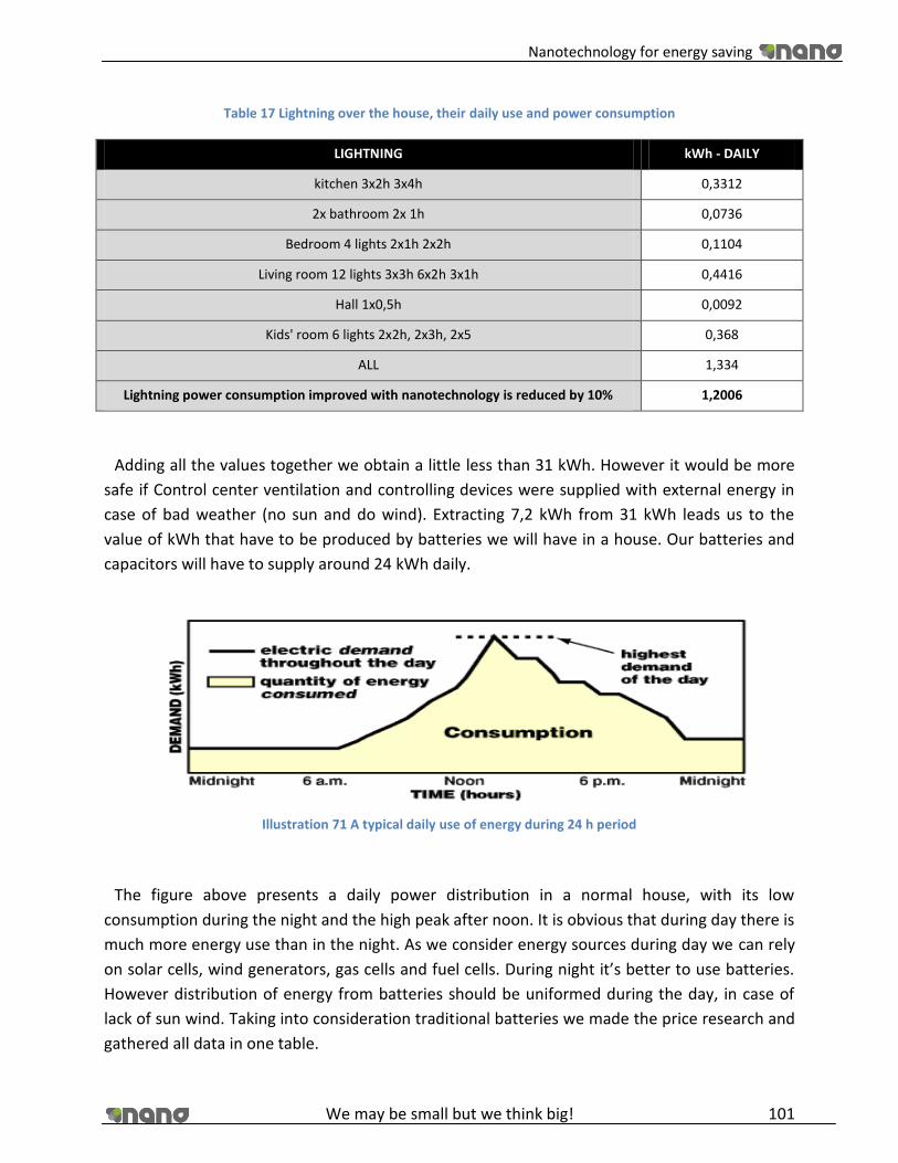
Nanotechnology for energy saving
We may be small but we think big! 101
Table 17 Lightning over the house, their daily use and power consumption
LIGHTNING kWh - DAILY
kitchen 3x2h 3x4h 0,3312
2x bathroom 2x 1h 0,0736
Bedroom 4 lights 2x1h 2x2h 0,1104
Living room 12 lights 3x3h 6x2h 3x1h 0,4416
Hall 1x0,5h 0,0092
Kids' room 6 lights 2x2h, 2x3h, 2x5 0,368
ALL 1,334
Lightning power consumption improved with nanotechnology is reduced by 10% 1,2006
Adding all the values together we obtain a little less than 31 kWh. However it would be more
safe if Control center ventilation and controlling devices were supplied with external energy in
case of bad weather (no sun and do wind). Extracting 7,2 kWh from 31 kWh leads us to the
value of kWh that have to be produced by batteries we will have in a house. Our batteries and
capacitors will have to supply around 24 kWh daily.
Illustration 71 A typical daily use of energy during 24 h period
The figure above presents a daily power distribution in a normal house, with its low
consumption during the night and the high peak after noon. It is obvious that during day there is
much more energy use than in the night. As we consider energy sources during day we can rely
on solar cells, wind generators, gas cells and fuel cells. During night it’s better to use batteries.
However distribution of energy from batteries should be uniformed during the day, in case of
lack of sun wind. Taking into consideration traditional batteries we made the price research and
gathered all data in one table.
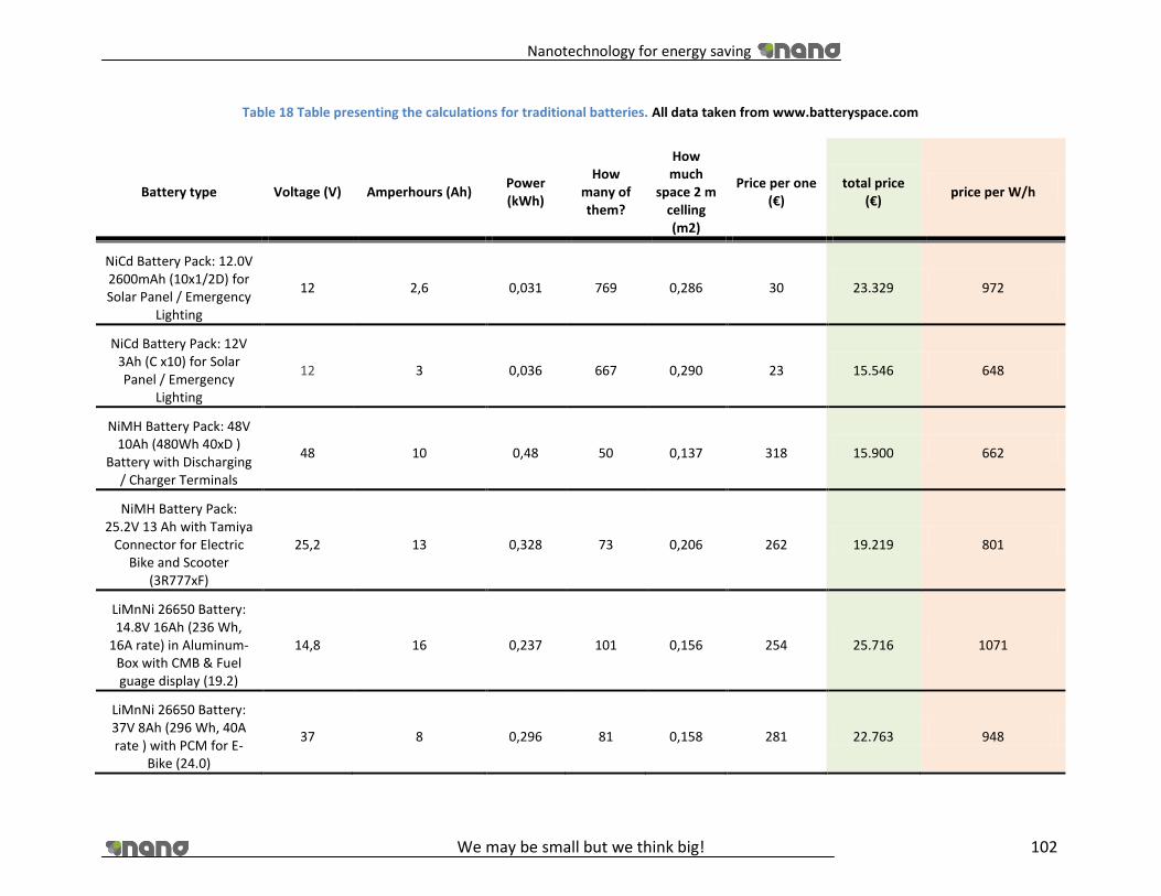
Nanotechnology for energy saving
We may be small but we think big! 102
Table 18 Table presenting the calculations for traditional batteries. All data taken from www.batteryspace.com
Battery type Voltage (V) Amperhours (Ah) Power (kWh)
How many of them?
How much
space 2 m celling (m2)
Price per one (€)
total price (€)
price per W/h
NiCd Battery Pack: 12.0V 2600mAh (10x1/2D) for Solar Panel / Emergency
Lighting
12 2,6 0,031 769 0,286 30 23.329 972
NiCd Battery Pack: 12V 3Ah (C x10) for Solar Panel / Emergency
Lighting
12 3 0,036 667 0,290 23 15.546 648
NiMH Battery Pack: 48V 10Ah (480Wh 40xD )
Battery with Discharging / Charger Terminals
48 10 0,48 50 0,137 318 15.900 662
NiMH Battery Pack: 25.2V 13 Ah with Tamiya
Connector for Electric Bike and Scooter
(3R777xF)
25,2 13 0,328 73 0,206 262 19.219 801
LiMnNi 26650 Battery: 14.8V 16Ah (236 Wh,
16A rate) in Aluminum-Box with CMB & Fuel guage display (19.2)
14,8 16 0,237 101 0,156 254 25.716 1071
LiMnNi 26650 Battery: 37V 8Ah (296 Wh, 40A rate ) with PCM for E-
Bike (24.0)
37 8 0,296 81 0,158 281 22.763 948

Nanotechnology for energy saving
We may be small but we think big! 103
LiFePO4 26650 Battery: 38.4V 6.6Ah (253 Wh,
30A rate) with PCM (23.76)
38,4 6,6 0,253 95 0,205 308 29.181 1216
LiFePO4 26650 Battery : 12.8V 13.2Ah (168Wh, 16A rate) in Aluminum-
Box with CMB & Fuel guage display (15.84)
12,8 13,2 0,169 142 0,546 242 34.405 1434
Powerizer Polymer Li-Ion Battery: 14.8v 3.6Ah
(53.28Wh, 30C) w/o PCB for RC Flight--- CE listed /
UN Approved (4.32)
14,8 3,6 0,053 450 0,093 71 32.104 1338
Powerizer Polymer Li-Ion Battery: 18.5v 3.6Ah
(66.6Wh, 30C) w/o PCB for RC Flight--- CE listed /
UN Approved (5.4)
18,5 3,6 0,067 360 0,097 82 29.523 1230
Li-Ion 14430 11.1 V 600 mah battery module (6.66Wh , 1.2A rate) with PCB&Polyswitch
(0.54)
11,1 0,6 0,007 3604 0,107 16 58.367 2432
Li-ion 18650 Box Battery: 14.8V 5.2Ah (77Wh,
Trail-Tech Female plug) with Fuel Guage &
On/Off Switch (6.24)
14,8 5,2 0,077 312 0,123 106 33.117 1380

Nanotechnology for energy saving
We may be small but we think big! 104
One can see that installing a backup system consisting from batteries is a really expensive
investment. Prices are even up to € 33,636 and the cheapest solution is around € 15,583 (NiCd
Battery Pack: 12V 3Ah (C x10)).
Our next step was to investigate the Newer technology, these are ultracapacitors. We chosen
LS Ultracapacitors manufactured by LS Mtron Company. They are producing capacitors as single
batteries and in modules. However we had a small problem with receiving the data considering
the prices for single batteries.
Table 19 Table presenting calculations for single ultracapacitors
LS ULTRACAPACITOR
TYPE
VOLTAG
E (V)
CAPACITANCE
(F)
DC ESR
(mΩ) kWh
HOW
MANY?
HOW MUCH SPACE
1 m HIGH (m2)
LSUC 002R7R0003F EA 2,7 3 100 3,04E-06 7901235 2,48
LSUC 002R7R0005F EA 2,7 5 75 5,06E-06 4740741 1,49
LSUC 002R7R0010F EA 2,7 10 50 1,01E-05 2370370 1,15
LSUC 002R7R0025F EA 2,7 25 35 2,53E-05 948148 0,62
LSUC 002R7R0050F EA 2,7 50 25 5,06E-05 474074 0,56
LSUC 002R8S0100F EA 2,7 100 9 1,01E-04 237037 0,38
LSUC 002RS80120F EA 2,8 120 9 1,31E-04 183673 0,33
LSUC 002R8L0350F EA 2,8 350 3,2 3,81E-04 62974 0,21
LSUC 002R8L0400F EA 2,8 400 3 4,36E-04 55102 0,22
LSUC 002R8P1000F EA 2,8 1000 0,58 1,09E-03 22041 3,69
LSUC 002R8P1700F EA 2,8 1700 0,5 1,85E-03 12965 3,36
LSUC 002R8P3000F EA 2,8 3000 0,36 3,27E-03 7347 3,44
LSUC 002R8P3000F EA 2,8 3000 0,35 3,27E-03 7347 3,44
LSUC 002R5S0100F EP 2,5 100 14 8,68E-05 276480 0,50
LSUC 002R5L0300F EP 2,5 300 5 2,60E-04 92160 0,31
LSUC 002R5P2800F EP 2,5 2800 0,65 2,43E-03 9874 4,63
LSUC 002R5S0220F EA 2,5 220 18 1,91E-04 125673 0,23
LSUC 002R5L0650F EA 2,5 650 8 5,64E-04 42535 0,14
LSUC 002R5L0850F EA 2,5 850 7 7,38E-04 32527 0,13
LSUC 002R5P1800F EA 2,5 1800 0,9 1,56E-03 15360 2,57
LSUC 002R5P5400F EA 2,5 5400 0,5 4,69E-03 5120 2,40

Nanotechnology for energy saving
We may be small but we think big! 105
One can see that using single ultracapacitors is ineffective because we will need a lot them,
and connecting them together into a one system would be a really hard work. However we
found a solution to use modules of ultracapacitors. Again we have made calculations for them
similar to previous ones.
Table 20 Table presents calculations for the modules of capacitors
LS ULTRA-
CAPACITOR
TYPE
VOLTAGE
(V)
CAPACITANCE
(F)
DC
ESR
(mΩ)
kWh HOW
MANY?
HOW
MUCH
SPACE
1 m
high
(m2)
PRICE
PER
ONE
€
TOTAL
PRICE €
PRICE PER
kwh
6 Series 16,8 500 3 1,96E-02 1 224 3,18 550 673 469 34 515
12 Series 33,6 250 6 3,92E-02 612 6,37 930 569 388 29 181
18 Series 50,4 166 9 5,86E-02 410 6,39 1450 594 214 30 453
One can see from these calculations that prices for ultracapacitors backup system are even 20
times higher! This is a great amount of money and there is no possibility to make such backup
system, it is simply too pricy. However during our project we analyzed some data and found that
prices of nanotechnology products can drop from 10 up to 100 fold down in next ten years. This
is very promising because then it will be very easy to buy and apply this technology.
100 fold drop down
For ultracapacitors
Conventional
batteries prices
8 284 40 000
7 003 19 000
We also have to keep in mind that ultracapacitors are not real nanocapacitors. They only use
activated carbon. If we consider a real nanocapacitors, for example the most promising ones
with silicon nanotubes we can expect 10 times more capacitance per one battery. That lead us
to 10 times less batteries used. Connecting this with low prices will lead us to a clean, safe and
cheap source of energy.

Nanotechnology for energy saving
We may be small but we think big! 106
Calculations
All sample calculations are done for LS ultracapacitor 6 series module with the need of 24 kWh
daily.
𝑃𝑜𝑤𝑒𝑟 (𝑘𝑊) = 𝑉𝑜𝑙𝑡𝑎𝑔𝑒 (𝑉)×𝐶𝑎𝑝𝑎𝑐𝑖𝑡𝑎𝑛𝑐𝑒 (𝐹)
3600 𝑠𝑒𝑐×1 000 𝑃𝑜𝑤𝑒𝑟 =
16,8 (𝑉)×500 (𝐹)
3600 𝑠𝑒𝑐×1 000= 1,96 × E−0,2
𝐻𝑜𝑤 𝑚𝑎𝑛𝑦 ? = 24𝑘𝑊/𝑃𝑜𝑤𝑒𝑟 𝐻𝑜𝑤 𝑚𝑎𝑛𝑦? =24𝑘𝑊
1,96× 𝐸−0,2 = 1 224
𝑇𝑒𝑜𝑟𝑒𝑡𝑖𝑐𝑎𝑙 𝑆𝑝𝑎𝑐𝑒 (𝑚2) =𝐷𝑖𝑚𝑒𝑛𝑠𝑖𝑜𝑛𝑠 (𝑚3) × 𝑁𝑢𝑚𝑏𝑒𝑟 𝑜𝑓 𝑏𝑎𝑡𝑡𝑒𝑟𝑖𝑒𝑠
1𝑚
𝑇𝑒𝑜𝑟𝑒𝑡𝑖𝑐𝑎𝑙 𝑆𝑝𝑎𝑐𝑒(𝑚2) =0,0052 𝑚3 × 1224
1𝑚= 3,18
𝑇𝑜𝑡𝑎𝑙 𝑃𝑟𝑖𝑐𝑒 ( €) = 𝑁𝑢𝑚𝑏𝑒𝑟 𝑜𝑓 𝑏𝑎𝑡𝑡𝑒𝑟𝑖𝑒𝑠 × 𝑃𝑟𝑖𝑐𝑒 ( €)
𝑇𝑜𝑡𝑎𝑙 𝑃𝑟𝑖𝑐𝑒 ( €) = 1 224 × 550 € = 673 469 ( €)
7. Future applications
7.1.1. Saving water with nanotechnology
A possible future application of nanotechnology could be to purify dirty water through filters,
Currently a Company from Florida called Dais Analytic is making great progress with
nanotechnology, a solid film with interconnected nanostructures that can filter waste out of
water down to a few parts per billion and provide safe, clean drinking water. The process
requires only about half the energy of current treatment technologies. This technology opens
up the possibility that you can take effluent water of any quality and return it as potable and
close the loop.
Saving water is saving energy so we thought it should at least name this application
8. Bucky paper
Bucky paper is a thin paper like sheet made from carbon nanotubes. It has outstanding
specification – the mass is ten times lower than the mass of steel, and it is also 500 times
stronger.

Nanotechnology for energy saving
We may be small but we think big! 107
It can be used to produce armors. It also has a great ability in conducting heat and electric
current. Due to that facts there are mane researches concerning future use of buckypaper.
Buckypaper can also illuminate, when it is exposed for a proper voltage. Some scientists suggest
that it can be useful for electronic devices and displays. Also using it as a heatsink could be good
idea. Other ways to use buckypaper are filters, or sensors. There are many ways to fabricate
buckypaper, and still many new are being developed. The simplest way to manufacture
buckypaper is to crush nanotubes together. Another method involves some chemical reactants.
Generally speaking, buckypaper due to its durability and low mass can revolutionize our life,
starting form medicine, aircrafts and vehicles, and finishing on every-day electronics. To better
understand the meaning of buckypaper in future electronics, we are going to build our own
capacitor, basing on this material.
9. Laboratory work report
Our capacitor consisted of two thin layers of buckypaper and a layer of separator between
them. The separator was simply a paper submerged in salted water. The construction of this
capacitor is a standard SLC. It was a disc with a diameter of 50mm.
Illustration 72 Capacitor with bucky paper
In our laboratory room we had two measuring devices available. The first one was the
oscilloscope, and the second one was the special device for measuring the capacitance. Using
this equipment we were able to create a specification of our buckypaper capacitor and also
compare it with standard and super capacitor.

Nanotechnology for energy saving
We may be small but we think big! 108
Illustration 73 Measuring stand
At the beginning let us consider the buckypaper capacitor. Measuring stand consist of 1,5V
battery, resistor 15kOhms and oscilloscope. The curve below shows the discharge curve of the
capacitor. There is also attached a curve without a capacitor for comparison. Important thing to
notice is fact, that we were using only 1,5V battery to charge the capacitor. Theoretically it
should stand about 2,5-2,7V but we decided to lower the voltage to prevent the water from
electrolysis and gasification.
Illustration 74 Oscilloscope
Another value to measure was the capacitance. For that purpose we have used a special
machine. The first step was to set the approximated capacitance of capacitor. Then, the
measurement was performed automatically. The results are as seen below.
We have reached the capacitance of 670uF, which was rather small for this nano capacitor. We
have deiced to repeat the measurement, but the result was even worse (633uF). Obviously
something was wrong. After short discussion, we came up with the idea that the separator layer

Nanotechnology for energy saving
We may be small but we think big! 109
is simply too thick for this low voltage. We have repeated the measurement once again, but
now with only one layer of buckypaper, and no separator. We were surprised, as the
capacitance broke the limit of 1mF and reached the value of 1,03mF.
This is a good value for a capacitor with dimensions as ours.
Illustration 75 Device for measuring capacitance
In order to clearly understand the possibilities of nanotechnology, we have also tried to
compare the standard and super capacitor. Those capacitors had almost the same dimensions.
The first one has a capacitance of 100uF and operational voltage of 25V.
We calculate that energy stored in this capacitor is:
𝐸 =1
2𝐶 ∗ 𝑉2 = 3,12 ∗ 10−2𝐽
The ultracapacitor has lower operation voltage (2,7V), but also has much greater capacitance
(5F)
𝐸 = 1,82 𝐽
We can see that energy density in ultracapacitor is over 58 times higher than in traditional
one.

Nanotechnology for energy saving
We may be small but we think big! 110
Illustration 76 Energy stored in cspscitors
The chart above clearly presents the difference between those two solutions.
Illustration 77 The capacitor on the left is a traditional electrolytic capacitor
The capacitor seen on the right hand side is a supercapacitor. It consists of two layers of
activated carbon that forms a porous structure, greatly improving the internal surface. As you
can see, the capacitors have equal dimensions. However, energy stored in each capacitor
greatly differs.
Summing all up, the nanotechnology can greatly improve the specification of capacitors. Using
activated carbon has numerous advantages. Capacitors using that technology provide
thousands of charge-discharge cycles, with a very low degradation factor. They have great
power density and power output, and at the same time, they have extremely low internal
0
0,2
0,4
0,6
0,8
1
1,2
1,4
1,6
1,8
2
Energy stored in capacitors
Traditional capacitor
Ultracapacitor

Nanotechnology for energy saving
We may be small but we think big! 111
resistance. Those types of capacitors are also much environmental friendly as they do not
consist of any toxic electrolyte. There is also no danger of overcharging.
As every technology, this one also has some drawbacks. The main one that has to be
considered is the low voltage per each capacitor - around 2,7V. This limitation is due to fact,
that in higher voltages, water would undergo the process of electrolysis that could destroy the
capacitor. Connecting those capacitors in series solves that process, but it also causes faster
self-discharge of the capacitor.
10. Conclusions
As a group we were enthusiastic about our chosen topic from the very beginning for many
reasons. The main thing that has to be said is that the issue of renewable energy is one of the
biggest in the world at this moment in time. The fact is that fossil fuels are destroying our planet
and changing the climate day by day, this cannot be denied. The greenhouse gas problem was
known about by both politicians and scientists decades ago yet nothing has been done until
recently. This delay in action makes it all the more important that we do all we can to rectify the
situation as quickly as possible before it is too late. After the Kyoto convention, all the advanced
countries of the world set themselves targets to meet by 2020 in terms of amount of energy
created from renewable sources. Most countries have a target of 15-20% but at the moment
only Germany and the UK are on track to meet this goal.
Our group focused on one new type of technology which can be used in the renewable energy
sector, this is nanotechnology. As explained in the report, nanotechnology works by decreasing
the size of molecules down to something under 100µm. When something is this small it gains
some fascinating new characteristics such as a massive volume to mass ratio, high electrical
conductivity and excellent insulation properties among other things. Not only this,
nanotechnology can be used to make devices smaller and more reliable.
Nanotechnology can be used to improve almost every part of our lives. There are also medical
uses for carbon nanotubes where they can be used to treat diseases but for our project we
focused on their energy saving abilities as we constructed an energy saving house consisting of
nano appliances. We used a conventional energy saving house as a comparison for our study
and we looked at the differences in terms of efficiency and cost in relation to our nano house.

Nanotechnology for energy saving
We may be small but we think big! 112
We found from our research that most nano appliances are still very much in the development
stage with products not yet released even though the theory is ready. Within 5 years it can be
expected that production and market entry will begin as most products are almost on the verge
of coming out. At the present moment though, nano products can be used alongside
conventional energy saving devices in what is called a hybrid method. This way conventional
energy saving can be improved gradually more and more, and hopefully 5 or 10 years down the
line it will be completely nano with extremely high efficiency levels.
The use of nanotechnology to generate, store, convert and insulate the energy needed for a
regular house to operate was found to be much more efficient than when conventional energy
saving techniques were used. After a detailed study of the current market and of the expected
change in the market, it can be predicted that when the demand for nano materials rises, the
cost of production and purpose will fall dramatically so that they will overtake all current forms
of energy saving technology. This is a hugely positive step for the planet as this switch in energy
consumption habits will slow down global warming greatly and help us to find a complete
replacement for fossil fuels in time to save the environment. This being said, at the moment
nano materials are too expensive, too early in development and have not been safety tested
enough to be brought out for public use.

Nanotechnology for energy saving
We may be small but we think big! 113
11. Sources
http://www.hydrogencarsnow.com/blog2/index.php/fuel-cells/sub-nano-platinum-
particles-power-fuel-cells/ [12]
http://www.physorg.com/news11044.html [27]
http://www.fuelcells.org/info/library/fchandbook.pdf [13]
www.wikipedia.org [9]
www.strath.ac.uk [10]
http://www.sciencedirect.com [15]
http://www.goldbulletin.org [14]
http://efektywne-ogrzewanie.pl/koszty-ogrzewania-domu/ [43]
http://www.ogrzewnictwo.pl/index.php?akt_cms=77&cms=183 [48]
http://www.uponor.com.pl [41]
http://www.lifetimeroofingltd.com/wp-content/ [42]
http://www.ufh.biz/mediac/400_0/media/ [49]
http://www.aerogel.org/ [44]
http://www.brinkclimatesystems.nl/renovent-hr/1696 [46]
http://www.aerogel.com/markets/building.html [45]
http://www.efficientwindows.org/ [47]
www.nanomercado.com/supercondensador-nanoestructurado-
gracia/_C3VTDDatmVFzWaF4O1n_f6qQsNXbt8ra8Y2EXDTGqI_-_d7ZjjaBIbkta0CBqIzJ
http://ecopowerchile.com/blog/?p=1567
http://encuentronano.fan.org.ar/ponencias_resultados.htm [6]
http://www.biodisol.com/medio-ambiente/generador-de-energia-eolica-domestica-
energias-limpias-turbinas-domiciliarias/ [16]
http://www.eagle.fi/index.asp?pn=1&kieli=2&aihe=68&avaa=Windpower [19]
http://medioambienteok.blogspot.com/2008/08/austrowind-presenta-una-elica-
domstica.html [18]
http://www.windenergy.com/index_wind.htm [21]
http://www.eaglepower.co.uk/Enquiry.html [17]
http://www.ebrdrenewables.com/sites/renew/countries/Poland/profile.aspx#Wind [1]
http://www.research.bayer.es/edicion-21/nanotubos.aspx [20]
http://windtrends.meteosimtruewind.com/es/mapas_anomalia_viento.php?zone=POL
[2]
http://www.monografias.com/trabajos48/nanotecnologia/nanotecnologia.shtml [3]
http://bibing.us.es/proyectos/abreproy/11175/fichero/vol1%252Frv_T1_Motivaciones_
v04.pdf http://www.baytubes.com/downloads/bms_cnt_baytubes_en.pdf [5]

Nanotechnology for energy saving
We may be small but we think big! 114
http://www.euroresidentes.com/Blogs/avances_tecnologicos/2004/06/nano-cables-
capaces-de-detectar-gases.htm [7]
http://www.euroresidentes.com/Blogs/avances_tecnologicos/2004/06/los-tejidos-
inteligentes-la-ropa-del.htm [8]
http://www.pa.msu.edu/cmp/csc/nanotube.html [22]
http://www.cecu.es/campanas/medio%20ambiente/res&rue/htm/guia/eolica.htm
http://www.marketsandmarkets.com/nanomaterials-market-research-63.html
Nano Road Map_ Energy [28]
http://www.elpais.com/articulo/futuro/ [4]
http://sisbib.unmsm.edu.pe/bibvirtualdata/tesis/basic/alcca_qf/cap5.PDF [23]
http://www.madrimasd.org/informacionidi/biblioteca/publicacion/doc/vt/vt11_nanotu
bos.pdf [24]
http://www.solartec.org/SVbioclimatica.htm
http://en.wikipedia.org/wiki/Battery_(electricity) [50]
http://pl.wikipedia.org/wiki/Akumulator_niklowo-kadmowy [51]
http://pl.wikipedia.org/wiki/Akumulator_kwasowo-ołowiowy [52]
http://pl.wikipedia.org/wiki/Akumulator_niklowo-metalowo-wodorkowy [53]
http://en.wikipedia.org/wiki/Nickel-zinc_battery [54]
http://pl.wikipedia.org/wiki/Akumulator_litowo-jonowy [55]
http://pl.wikipedia.org/wiki/Akumulator_litowo-polimerowy [56]
http://www.electrochem.org/dl/ma/203/pdfs/1685.pdf [57]
http://www.electrochem.org/dl/ma/200/pdfs/0034.pdf[58]
http://www.electrochem.org/meetings/scheduler/abstracts/210/0252.pdf[59]
http://en.wikipedia.org/wiki/Nanowire_battery [60]
http://www.treehugger.com/files/2009/09/silicon-nanotubes-anodes-boost-lithium-ion-
battery-capacity-10x.php [61]
http://www.electrochem.org/dl/ma/200/pdfs/0034.pdf[62]
“Nanocomposite PEO-based polymer electrolyte using a highly porous, super acid
zirconia filler”
Gaelle Derrien b, Jusef Hassoun a, Simone Sacchetti a, Stefania Panero a
Solid State Ionics 180 (2009) 1267–1271 [63]
http://pubs.acs.org/doi/abs/10.1021/nl902058c?journalCode=nalefd [64]
http://scitation.aip.org/getpdf/servlet/GetPDFServlet?filetype=pdf&id=MAECES0006020
00005000254000001&idtype=cvips&prog=normal [65]
http://www.technewsworld.com/story/58833.html?wlc=1274911067 [66]
http://en.wikipedia.org/wiki/Capacitor [67]
http://en.wikipedia.org/wiki/Electrolytic_capacitor [68]

Nanotechnology for energy saving
We may be small but we think big! 115
http://hobby_elec.piclist.com/e_capa.htm [69]
http://en.wikipedia.org/wiki/Supercapacitors [70]
http://peswiki.com/index.php/Directory:MIT_Nanotube_Super_Capacitor[71]
http://lees.mit.edu/lees/posters/RU13_Oct05.pdf [72]
http://www.energiasrenovables.ciemat.es/suplementos/sit_actual_renovables/biogas.h
tm[36]
http://europa.eu/rapid/pressReleasesAction.do?reference=MEMO/09/144&format=HT
ML&aged=0&language=EN&guiLanguage=en [35]
http://www.upc.edu/grecdh/pdf/2008_JMH_Guia_biodigestores.pdf [37]
http://news.mongabay.com/bioenergy/2007/07/study-eu-biogas-production-grew-136-
in.html [33]
http://europa.eu/rapid/pressReleasesAction.do?reference=MEMO/09/144&format=HT
ML&aged=0&language=EN&guiLanguage=en [34]
http://www.nanomaterialstore.com/nano-phosphor.php [29]
http://www.treehugger.com/files/2010/01/ces-2010-nanosys-using-nanotechnology-to-
make-led-lighting-more-beautiful.php [32]
http://www.vanderbilt.edu/exploration/stories/quantumdotled.html [31]
http://www.energy.eu/ [26]
http://www.biogasmax.eu/media/1t1_biogas_production_in_poland__050402600_0649
_30092009.pdf [38]
http://www.Philips.com/ [25]
http://www.economist.com/ [30]
http://www.siemens.com/ [39]
http://www.glacierbaytechnology.com/category/insulation/ultra-r-thermal-insulation/
[40]

Nanotechnology for energy saving
We may be small but we think big! 116
12. Plan of the house (A3 Page)

Nanotechnology for energy saving
We may be small but we think big! 117
13. Annexes
13.1. Annex I European regulation for efficiency appliances
MEMO/09/144
Brussels, 31 March 2009
New format for the Energy Label and ecodesign requirements for household refrigerating
appliances and TVs
On 30 and 31 March 2009, the Commission submitted for endorsement by the Committee of
Member States, draft Directives for the energy labelling of household refrigerating appliances,
televisions, washing machines and dishwashers.
Fridges and freezers, washing machines and dishwashers (as well as washer-dryers, tumble
dryers, lamps, ovens, air-conditioners) are already labelled since the mid/end 90s. TVs are
currently not yet labelled.
The energy Label requires the manufacturers to declare how energy efficient/inefficient their
products are and to supply a label to retailers who have to display the label on the appliances
shown in shops. The aim is to provide credible and comparable information on the performance
of the products to consumers before they make their purchasing decision.
For all four product categories the Labelling directives are accompanied by Ecodesign
regulations, which set out the minimum level of efficiency that the appliances have to meet in
view of being placed on the market.
The new Label layout - Main characteristics:
Since it was introduced by the Commission in the mid 90s, the energy label was so successful
that today most products are in the "A" class. There was a need to go "beyond A", to allow
manufacturers to further compete by developing products that are more and more efficient and
to show how much better they are for consumers who could then make well informed choices.
By buying more energy efficient appliances, consumers might pay higher upfront prices but
make a profit on the lifetime of the appliance by saving on the running costs.
Nanotechnology for energy saving
We may be small but we think big! 118
The new label:
Is based on the A-G well known coloured scheme; Pre-defined additional classes e.g. "A-20%, A-
40% …" are added to the label on top of class A with a frequency which depends on the product
category and which is pre-defined in the Directives. The black arrow shall display how much
better the product is compared with an A class product.
In principle, the energy efficiency class of a particular model already on the market remains
unchanged (A is A). For fridges/freezers, there will be a transition with A+ fridges corresponding
to A-20%, A++ will be equivalent to A-40%.
Manufacturers who can put a product on the market that is more efficient than the top class
can show it on the label ahead of the date on which the display of a "higher" class becomes
mandatory.
The design of the new label is clearly different from the current design, i.e. new labels can be
clearly distinguished from existing labels during the transition period.
The label is "language-neutral" – using pictograms - so that suppliers will provide the label in
one piece without having costs for adapting to local language versions. This will also ensure that
the full label is shown in shops (and not just the strip).
The top class arrow on the left side of the label shall always be shown in dark green (as for the
current A class colour). That means that the colours will be uplifted each time a higher class is
introduced. Classes at the bottom will be in dark red (same as G colour today). The message
could be "buy green".
Advantages of the new label format:
consumers can judge at a glance how much "better than A" a product really is (20% more
efficient, 40% more efficient …), which is not the case with the current "A+/A++" naming of top
efficiency fridges and freezers; manufacturers can show in "real time" how much "better than
A" a product really is, which is not the case with the current system, not allowing to show
"better than A++" for fridges/freezers, and "better than A" for the other labelled products; there
will be no confusion for consumers between new and old classes as would have been the case if
products had been reclassified; retailers will have no additional burden for the transition from
"old" to "new" format, and it will be easier for the manufacturers and the retailers to label in
practise (full label is in the box, ready to be displayed in the show room).
Impact of the new label format: more incentives for innovation, resulting in an accelerated
"race" for top efficient products; boosting of market transformation towards high efficiency
products, and ultimately; energy and CO2 savings.

Nanotechnology for energy saving
We may be small but we think big! 119
Examples of the new label format:
TV label from 2012 Refrigerator/freezer label from 2012
Ecodesign requirements for household refrigerating appliances
Application date Energy Efficiency Index (EEI)
1 July 2010 EEI < 55
i.e. equivalent to removing current classes B,C and below
1 July 2012 EEI < 44
i.e. equivalent to removing current class A (current classes A+
and above will remain)
1 July 2014 EEI < 42
i.e. only current classes A+ and above will remain
Ecodesign requirements for household washing machines
APPLICATION DATE ENERGY EFFICIENCY INDEX (EEI)
1 July 2010 EEI < 68
i.e. equivalent to removing current classes B,C and below
1 July 2013 EEI < 59 with rated capacity c ≥ 4kg
i.e. equivalent to removing current class A (=only current classes A+ and
above will remain)
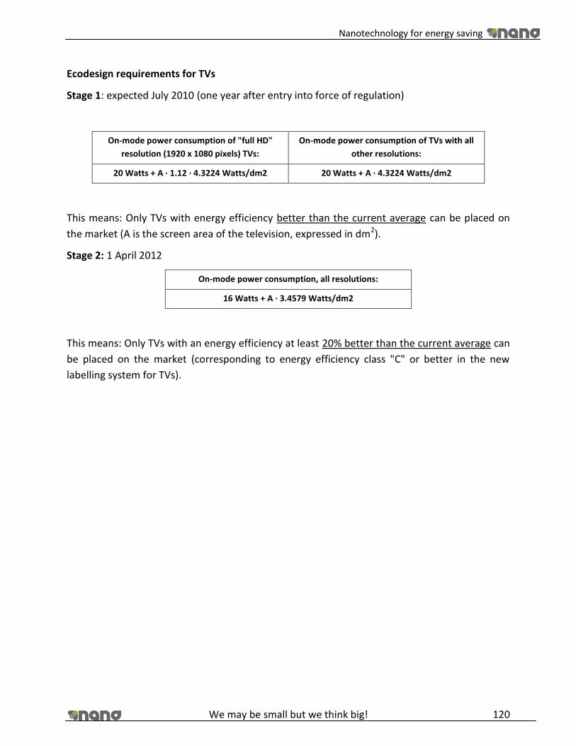
Nanotechnology for energy saving
We may be small but we think big! 120
Ecodesign requirements for TVs
Stage 1: expected July 2010 (one year after entry into force of regulation)
On-mode power consumption of "full HD"
resolution (1920 x 1080 pixels) TVs:
On-mode power consumption of TVs with all
other resolutions:
20 Watts + A ∙ 1.12 ∙ 4.3224 Watts/dm2 20 Watts + A ∙ 4.3224 Watts/dm2
This means: Only TVs with energy efficiency better than the current average can be placed on
the market (A is the screen area of the television, expressed in dm2).
Stage 2: 1 April 2012
On-mode power consumption, all resolutions:
16 Watts + A ∙ 3.4579 Watts/dm2
This means: Only TVs with an energy efficiency at least 20% better than the current average can
be placed on the market (corresponding to energy efficiency class "C" or better in the new
labelling system for TVs).

Nanotechnology for energy saving
We may be small but we think big! 121
13.2. Annex II Printed results of the laboratory experiment.

Nanotechnology for energy saving
We may be small but we think big! 122

Nanotechnology for energy saving
We may be small but we think big! 123
13.3. Annex IV Meetings agenda (digital version)
13.4. Annex III Design and calculations of illumination of the house (PDF files)


