
EUROPEAN NEW CAR ASSESSMENT PROGRAMME · PDF fileELECTRONIC STABILITY CONTROL (ESC) SYSTEMS...
18
EUROPEAN NEW CAR ASSESSMENT PROGRAMME (Euro NCAP) THE DYNAMIC TEST OF CAR ELECTRONIC STABILITY CONTROL (ESC) SYSTEMS PROTOCOL Version 1.2 June 2011
Transcript of EUROPEAN NEW CAR ASSESSMENT PROGRAMME · PDF fileELECTRONIC STABILITY CONTROL (ESC) SYSTEMS...

EUROPEAN NEW CAR ASSESSMENT PROGRAMME
(Euro NCAP)
THE DYNAMIC TEST OF CAR
ELECTRONIC STABILITY CONTROL (ESC)
SYSTEMS PROTOCOL
Version 1.2
June 2011

Version 1.2
June 2011
Copyright ©Euro NCAP - This work is the intellectual property of Euro NCAP. Permission is granted for this
material to be shared for non-commercial, educational purposes, provided that this copyright statement
appears on the reproduced materials and notice is given that the copying is by permission of Euro NCAP. To
disseminate otherwise or to republish requires written permission from Euro NCAP.
Version 1.2
June 2011
CONTENTS
1. INTRODUCTION ............................................................................................... 1 2. DEFINITIONS ..................................................................................................... 1 3. REFERENCE SYSTEM ...................................................................................... 3 4. VARIABLES ....................................................................................................... 4 5. MEASURING EQUIPMENT .............................................................................. 5
6. TEST CONDITIONS........................................................................................... 6 7. TEST PROCEDURE ........................................................................................... 8 8. POST DATA PROCESSING ............................................................................ 10 9. PHOTOGRAPHIC AND VIDEO REQUIREMENTS ...................................... 11 APPENDIX I - VEHICLE SPECIFICATIONS .......................................................... 12
APPENDIX II - TEST CONDITIONS ........................................................................ 13
APPENDIX III - COORDINATE TRANSFORMATIONS ....................................... 14 APPENDIX IV – REFERENCES ............................................................................... 15
Version 1.2 1
June 2011
1. INTRODUCTION
This test specifies performance and equipment requirements for Electronic Stability Control
(ESC) systems. The purpose of this test is to reduce the number of deaths and injuries that
result from crashes in which the driver loses directional control of the vehicle, including
those resulting in vehicle rollover.
2. DEFINITIONS
For the purpose of this procedure, the following definitions shall apply:
2.1. Ackerman Steer Angle means the angle whose tangent is the wheelbase divided
by the radius of the turn at a very low speed.
2.2. Electronic Stability Control System or ESC System means a system that has all
of the following attributes:
(a) That improves vehicle directional stability by at least having the ability to
automatically control individually the braking torques of the left and right wheels
on each axle or an axle of each axle group1 to induce a correcting yaw moment
based on the evaluation of actual vehicle behaviour in comparison with a
determination of vehicle behaviour demanded by the driver;
(b) That is computer-controlled with the computer using a closed-loop algorithm
to limit vehicle oversteer and to limit vehicle understeer based on the evaluation of
actual vehicle behaviour in comparison with a determination of vehicle behaviour
demanded by the driver;
(c) That has a means to determine directly the value of vehicle's yaw rate and to
estimate its side slip or side slip derivative with respect to time;
(d) That has a means to monitor driver steering inputs; and
(e) That has an algorithm to determine the need, and a means to modify
propulsion torque, as necessary, to assist the driver in maintaining control of the
vehicle.
2.3. Lateral Acceleration means the component of the vector acceleration of a point in
the vehicle perpendicular to the vehicle x axis (longitudinal) and parallel to the road
plane.
2.4. Oversteer means a condition in which the vehicle's yaw rate is greater than the
yaw rate that would occur at the vehicle's speed as result of the Ackerman Steer
Angle.
2.5. Sideslip or side slip angle means the arctangent of the ratio of the lateral velocity
to the longitudinal velocity of the centre of gravity of the vehicle.
2.6. Understeer means a condition in which the vehicle's yaw rate is less than the yaw
rate that would occur at the vehicle's speed as result of the Ackerman Steer Angle.
2.7. Yaw rate means the rate of change of the vehicle's heading angle measured in
degrees/second of rotation about a vertical axis through the vehicle's centre of
gravity.
2.8. Peak braking coefficient (PBC): means the measure of tyre to road surface
friction based on the max deceleration of a rolling tyre.
2.9. Centre of Gravity (CoG): means the mean location of all the mass in the vehicle
at kerb weight and with a full fuel load. . In case the CoG height is not available or
supplied by the OEM, it will be approximated as 38% of maximum roof height.
1 An axle group shall be treated as a single axle and dual wheels shall be treated as a single wheel.
Version 1.2 2
June 2011
2.10. Static Stability Factor (SSF) means one-half the track width of a vehicle divided
by the height of its Centre of gravity:
SSF = T/2H
T = track width average of front and rear axle
H = height of the Centre of Gravity (CoG) of the vehicle at kerb weight and with a
full fuel load. By default it will be approximated as 38% of maximum roof
height. Where CoG height is measured and/or supplied by the OEM, these
values must be reported for monitoring purpose.
Version 1.2 3
June 2011
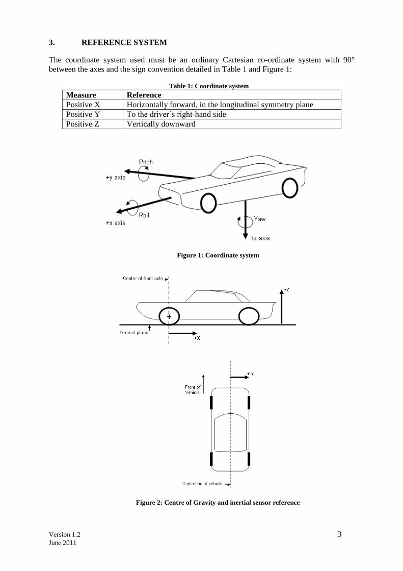
3. REFERENCE SYSTEM
The coordinate system used must be an ordinary Cartesian co-ordinate system with 90°
between the axes and the sign convention detailed in Table 1 and Figure 1:
Table 1: Coordinate system
Measure Reference
Positive X Horizontally forward, in the longitudinal symmetry plane
Positive Y To the driver‟s right-hand side
Positive Z Vertically downward
Figure 1: Coordinate system
Figure 2: Centre of Gravity and inertial sensor reference
Version 1.2 4
June 2011
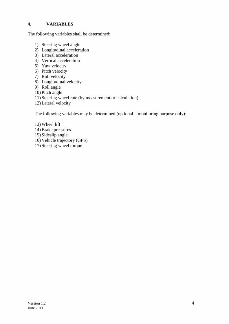
4. VARIABLES
The following variables shall be determined:
1) Steering wheel angle
2) Longitudinal acceleration
3) Lateral acceleration
4) Vertical acceleration
5) Yaw velocity
6) Pitch velocity
7) Roll velocity
8) Longitudinal velocity
9) Roll angle
10) Pitch angle
11) Steering wheel rate (by measurement or calculation)
12) Lateral velocity
The following variables may be determined (optional – monitoring purpose only):
13) Wheel lift
14) Brake pressures
15) Sideslip angle
16) Vehicle trajectory (GPS)
17) Steering wheel torque
Version 1.2 5
June 2011
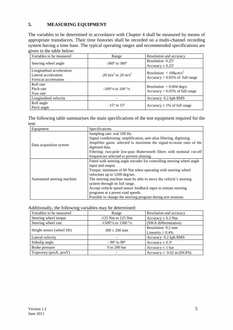
5. MEASURING EQUIPMENT
The variables to be determined in accordance with Chapter 4 shall be measured by means of
appropriate transducers. Their time histories shall be recorded on a multi-channel recording
system having a time base. The typical operating ranges and recommended specifications are
given in the table below: Variables to be measured Range Resolution and accuracy
Steering wheel angle -360º to 360º Resolution 0.25º
Accuracy 0.25º
Longitudinal acceleration
Lateral acceleration
Vertical acceleration
-20 m/s2 to 20 m/s
2
Resolution < 100m/s2
Accuracy < 0.05% of full range
Roll rate
Pitch rate
Yaw rate
-100º/s to 100 º/s Resolution < 0.004 deg/s
Accuracy + 0.05% of full range
Longitudinal velocity - Accuracy 0.2 kph RMS
Roll angle
Pitch angle -15º to 15º Accuracy 1% of full range
The following table summarises the main specifications of the test equipment required for the
test: Equipment Specifications
Data acquisition system
Sampling rate: real 100 Hz
Signal conditioning: amplification, anti-alias filtering, digitising.
Amplifier gains: selected to maximise the signal-to-noise ratio of the
digitised data.
Filtering: two-pole low-pass Butterworth filters with nominal cut-off
frequencies selected to prevent aliasing.
Automated steering machine
Fitted with steering angle encoder for controlling steering wheel angle
input and output.
Torque: minimum of 60 Nm when operating with steering wheel
velocities up to 1200 deg/sec.
The steering machine must be able to move the vehicle‟s steering
system through its full range.
Accept vehicle speed sensor feedback input to initiate steering
programs at a preset road speeds.
Possible to change the steering program during test sessions.
Additionally, the following variables may be determined: Variables to be measured Range Resolution and accuracy
Steering wheel torque -125 Nm to 125 Nm Accuracy 0.3 Nm
Steering wheel rate -1500º/s to 1500 º/s (SWA differentiation)
Height sensor (wheel lift) 300 200 mm Resolution 0.2 mm
Linearity 0.4%
Lateral velocity - Accuracy 0.2 kph RMS
Sideslip angle - 90º to 90º Accuracy 0.3º
Brake pressure 0 to 200 bar Accuracy 1 bar
Trajectory (posX, posY) - Accuracy 0.02 m (DGPS)
Version 1.2 6
June 2011
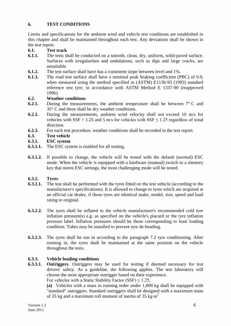
6. TEST CONDITIONS
Limits and specifications for the ambient wind and vehicle test conditions are established in
this chapter and shall be maintained throughout each test. Any deviations shall be shown in
the test report.
6.1. Test track
6.1.1. The tests shall be conducted on a smooth, clean, dry, uniform, solid-paved surface.
Surfaces with irregularities and undulations, such as dips and large cracks, are
unsuitable.
6.1.2. The test surface shall have has a consistent slope between level and 1%.
6.1.3. The road test surface shall have a minimal peak braking coefficient (PBC) of 0.9,
when measured using the method specified in (ASTM) E1136-93 (1993) standard
reference test tyre, in accordance with ASTM Method E 1337-90 (reapproved
1996).
6.2. Weather conditions
6.2.1. During the measurements, the ambient temperature shall be between 7° C and
35° C and there shall be dry weather conditions.
6.2.2. During the measurements, ambient wind velocity shall not exceed 10 m/s for
vehicles with SSF > 1.25 and 5 m/s for vehicles with SSF ≤ 1.25 regardless of wind
direction.
6.2.3. For each test procedure, weather conditions shall be recorded in the test report.
6.3. Test vehicle
6.3.1. ESC system
6.3.1.1. The ESC system is enabled for all testing.
6.3.1.2. If possible to change, the vehicle will be tested with the default (normal) ESC
mode. When the vehicle is equipped with a hardware (manual) switch or a memory
key that stores ESC settings, the most challenging mode will be tested.
6.3.2. Tyres
6.3.2.1. The test shall be performed with the tyres fitted on the test vehicle (according to the
manufacturer's specifications). It is allowed to change to tyres which are acquired at
an official car dealer, if those tyres are identical make, model, size, speed and load
rating to original.
6.3.2.2. The tyres shall be inflated to the vehicle manufacturer's recommended cold tyre
inflation pressure(s) e.g. as specified on the vehicle's placard or the tyre inflation
pressure label. Inflation pressures should be those corresponding to least loading
condition. Tubes may be installed to prevent tyre de-beading.
6.3.2.3. The tyres shall be run in according to the paragraph 7.2 tyre conditioning. After
running in, the tyres shall be maintained at the same position on the vehicle
throughout the tests.
6.3.3. Vehicle loading conditions
6.3.3.1. Outriggers. Outriggers may be used for testing if deemed necessary for test
drivers' safety. As a guideline, the following applies. The test laboratory will
choose the most appropriate outrigger based on their experience.
For vehicles with a Static Stability Factor (SSF) ≤ 1.25;
(a) Vehicles with a mass in running order under 1,800 kg shall be equipped with
"standard" outriggers. Standard outriggers shall be designed with a maximum mass
of 35 kg and a maximum roll moment of inertia of 35 kg∙m2
Version 1.2 7
June 2011
(b) Vehicles with a mass in running order equal to or greater than 1,800 kg shall
be equipped with "heavy" outriggers. Heavy outriggers shall be designed with a
maximum mass of 40 kg and a maximum roll moment of inertia of 40 kg∙m2.
6.3.3.2. The vehicle is loaded with the fuel tank filled to at least 90 per cent of capacity, and
a total interior load of 168 kg comprised of the test driver and test equipment
(automated steering machine, data acquisition system and the power supply for the
steering machine), and ballast as required to make up for any shortfall in the weight
of test drivers and test equipment.
6.3.3.3. Unladen Kerb Mass
6.3.3.3.1. Fill up the tank with fuel to 100% of the tank‟s capacity of fuel.
6.3.3.3.2. Check the oil level and top up to its maximum level if necessary. Similarly, top up
the levels of all other fluids to their maximum levels if necessary.
6.3.3.3.3. Ensure that the vehicle has its spare wheel on board, if fitted, along with any tools
supplied with the vehicle. Nothing else should be in the car.
6.3.3.3.4. Ensure that all tyres are inflated according to the manufacturer‟s instructions for the
appropriate loading condition.
6.3.3.3.5. Measure the front and rear axle masses and determine the total mass of the vehicle.
The total mass is the „unladen kerb mass‟ of the vehicle. Record this mass in the
test details.
6.3.3.3.6. If outriggers are required by the SSF, mount the outriggers to the vehicle and repeat
paragraph 6.3.3.3.5.
6.3.3.3.7. Calculate the required ballast mass, by subtracting the mass of the test driver and
test equipment from the required 168 kg interior load.
6.3.4. Wheel alignment measurement
6.3.4.1. The vehicle should be subject to a vehicle (in-line) geometry check to record the
wheel alignment set by the OEM. This should be done with the vehicle in test
weight, meaning kerb weight and full fuel load.
6.3.5. Vehicle Preparation
6.3.5.1. Fit the on-board test equipment and instrumentation in the vehicle. Also fit any
associated cables, cabling boxes and power sources.
6.3.5.2. Place weights with a mass of the ballast mass. Any items added should be securely
attached to the car.
6.3.5.3. With the driver in the vehicle, weigh the front and rear axle loads of the vehicle.
Compare these loads with those determined in paragraph 6.3.3.3.5.
6.3.5.4. The total vehicle mass shall be the unladen kerb plus full fuel load mass, plus
168kg +/- 1%. The front/rear axle load distribution needs to be within 5% of the
front/rear axle load distribution of the original unladen kerb mass plus full fuel
load. If the vehicle differs from the requirements given in this paragraph, items may
be removed or added to the vehicle which has no influence on its performance. Any
items added to increase the vehicle mass should be securely attached to the car.
6.3.5.5. Repeat paragraphs 6.3.5.3 and 6.3.5.4 until the front and rear axle loads and the
total vehicle mass are within the limits set in paragraph 6.3.5.4. Care needs to be
taken when adding or removing weight in order to approximate the original vehicle
inertial properties as close as possible. Record the final axle loads in the test details.
Version 1.2 8
June 2011
7. TEST PROCEDURE
7.1. Brake Conditioning. Condition the vehicle brakes using the method described:
7.1.1. Ten stops are performed from a speed of approximately 56 km/h, with an average
deceleration of approximately 0.5g.
7.1.2. Immediately following the series of approximately 56 km/h stops, three additional
stops are performed from 72 km/h at higher deceleration.
7.1.3. When executing these 3 stops, sufficient force is applied to the brake pedal to
activate the vehicle's antilock brake system (ABS) for a majority of each braking
event.
7.1.4. Following completion of the final stop in paragraph 7.1.2, the vehicle is driven at a
speed of approximately 72 km/h for five minutes to cool the brakes.
7.2. Tyre Conditioning. Condition the tyres to wear away mould sheen and achieve
operating temperature. Condition the tyres immediately before beginning the test
runs of paragraphs 7.3 and 7.4 using the method described:
7.2.1. The test vehicle is driven around a circle 30 metres in diameter at a speed that
produces a lateral acceleration of approximately 0.5g to 0.6g for three clockwise
laps followed by three counter clockwise laps.
7.2.2. Using a sinusoidal steering pattern at a frequency of 1 Hz, a peak steering wheel
angle amplitude corresponding to a peak lateral acceleration of 0.5g to 0.6g, and
a vehicle speed of approximately 56 km/h, the vehicle is driven through four passes
performing 10 cycles of sinusoidal steering during each pass.
7.2.3. The steering wheel angle amplitude of the final cycle of the final pass is twice that
of the other cycles. The maximum time permitted between each lap or pass is five
minutes.
7.3. Slowly Increasing Steer Procedure.
7.3.1. The vehicle is subjected to two series of runs of the Slowly Increasing Steer Test
using a constant vehicle speed of 80 ±2 km/h and a steering pattern that increases
by 13.5 degrees per second until a lateral acceleration of approximately 0.5g is
obtained. Three repetitions are performed for each test series. One series uses
counter clockwise steering, and the other series uses clockwise steering. The
maximum time permitted between each pass is five minutes.
7.3.2. From the Slowly Increasing Steer tests, the quantity "A" is determined. "A" is the
steering wheel angle in degrees that produces a steady state lateral acceleration
(corrected using the methods specified in paragraph 8.3) of 0.3g for the test vehicle.
Utilising linear regression, "A" is calculated, to the nearest 0.1 degrees, from each
of the six Slowly Increasing Steer tests. The absolute value of the six A's calculated
is averaged and rounded to the nearest 0.1 degrees to produce the final quantity, A,
used below.
7.3.3. After the quantity "A" has been determined, without replacing the tyres, the tyre
conditioning procedure described in paragraph 7.2 is performed immediately prior
to conducting the Sine with Dwell Test of paragraph 7.4.
7.3.4. Initiation of the first Sine with Dwell test series shall begin within two hours after
completion of the Brake Conditioning in paragraph 7.1.
7.3.5. Check that the ESC system is enabled by ensuring that the ESC malfunction and
"ESC Off" (if provided) tell-tales are not illuminated.
7.4. Sine with Dwell Test of Oversteer Intervention and Responsiveness.
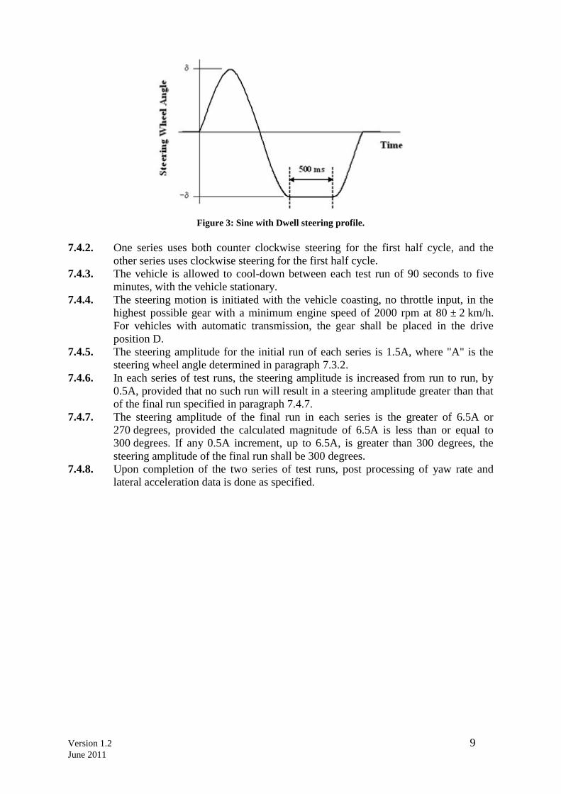
7.4.1. The vehicle is subjected to two series of test runs using a steering pattern of a sine
wave at 0.7 Hz frequency with a 500 ms delay beginning at the second peak
amplitude as shown in Figure 3 (the Sine with Dwell tests).
Version 1.2 9
June 2011
Figure 3: Sine with Dwell steering profile.
7.4.2. One series uses both counter clockwise steering for the first half cycle, and the
other series uses clockwise steering for the first half cycle.
7.4.3. The vehicle is allowed to cool-down between each test run of 90 seconds to five
minutes, with the vehicle stationary.
7.4.4. The steering motion is initiated with the vehicle coasting, no throttle input, in the
highest possible gear with a minimum engine speed of 2000 rpm at 80 ± 2 km/h.
For vehicles with automatic transmission, the gear shall be placed in the drive
position D.
7.4.5. The steering amplitude for the initial run of each series is 1.5A, where "A" is the
steering wheel angle determined in paragraph 7.3.2.
7.4.6. In each series of test runs, the steering amplitude is increased from run to run, by
0.5A, provided that no such run will result in a steering amplitude greater than that
of the final run specified in paragraph 7.4.7.
7.4.7. The steering amplitude of the final run in each series is the greater of 6.5A or
270 degrees, provided the calculated magnitude of 6.5A is less than or equal to
300 degrees. If any 0.5A increment, up to 6.5A, is greater than 300 degrees, the
steering amplitude of the final run shall be 300 degrees.
7.4.8. Upon completion of the two series of test runs, post processing of yaw rate and
lateral acceleration data is done as specified.
Version 1.2 10
June 2011
8. POST DATA PROCESSING: CALCULATIONS FOR PERFORMANCE
METRICS
Yaw rate and lateral displacement measurements and calculations shall be processed utilising
the techniques specified in paragraphs 8.1. to 8.9.
8.1. Raw steering wheel angle data is filtered with a 12-pole phase-less Butterworth
filter and a cut-off frequency of 10 Hz. The filtered data is then zeroed to remove
sensor offset utilising static pre-test data.
8.2. Raw yaw rate data is filtered with a 12-pole phase-less Butterworth filter and a cut-
off frequency of 6 Hz. The filtered data is then zeroed to remove sensor offset
utilising static pre-test data.
8.3. Raw lateral acceleration data is filtered with a 12-pole phase-less Butterworth filter
and a cut-off frequency of 6 Hz. The filtered data is then zeroed to remove sensor
offset utilising static pre-test data. The lateral acceleration data at the vehicle centre
of gravity is determined by removing the effects caused by vehicle body roll and by
correcting for sensor placement via use of coordinate transformation. For data
collection, the lateral accelerometer shall be located as close as possible to the
position of the vehicle's longitudinal and lateral centres of gravity.
8.4. Steering wheel velocity is determined by differentiating the filtered steering wheel
angle data. The steering wheel velocity data is then filtered with a
moving 0.1 second running average filter.
8.5. Lateral acceleration, yaw rate and steering wheel angle data channels are zeroed
utilising a defined "zeroing range". The methods used to establish the zeroing range
are defined in paragraphs 8.5.1 and 8.5.2.
8.5.1. Using the steering wheel rate data calculated using the methods described in
paragraph 8.4, the first instant steering wheel rate exceeding 75 deg/sec is
identified. From this point, steering wheel rate shall remain greater than 75 deg/sec
for at least 200 ms. If the second condition is not met, the next instant steering
wheel rate exceeding 75 deg/sec is identified and the 200 ms validity check
applied. This iterative process continues until both conditions are ultimately
satisfied.
8.5.2. The "zeroing range" is defined as the 1.0 second time period prior to the instant the
steering wheel rate exceeds 75 deg/sec (i.e. the instant the steering wheel velocity
exceeds 75 deg/sec defines the end of the "zeroing range").
8.6. The Beginning of Steer (BOS) is defined as the first instance filtered and zeroed
steering wheel angle data reaches - 5 degrees (when the initial steering input is
counter clockwise) or +5 degrees (when the initial steering input is clockwise) after
time defining the end of the "zeroing range". The value for time at the BOS is
interpolated.
8.7. The Completion of Steer (COS) is defined as the time the steering wheel angle
returns to zero at the completion of the Sine with Dwell steering manoeuvre. The
value for time at the zero degree steering wheel angle is interpolated.
8.8. The second peak yaw rate is defined as the first local yaw rate peak produced by
the reversal of the steering wheel. The yaw rates at 1.000 and 1.750 seconds after
COS are determined by interpolation.
8.9. Determine lateral velocity by integrating corrected, filtered and zeroed lateral
acceleration data. Zero lateral velocity at BOS event. Determine lateral
displacement by integrating zeroed lateral velocity. Zero lateral displacement at
BOS event. Lateral displacement at 1.07 seconds from BOS event is determined by
interpolation. Lateral displacement may also be determined using GPS data.
Version 1.2 11
June 2011
9. PHOTOGRAPHIC AND VIDEO REQUIREMENTS
9.1. Vehicle Markings
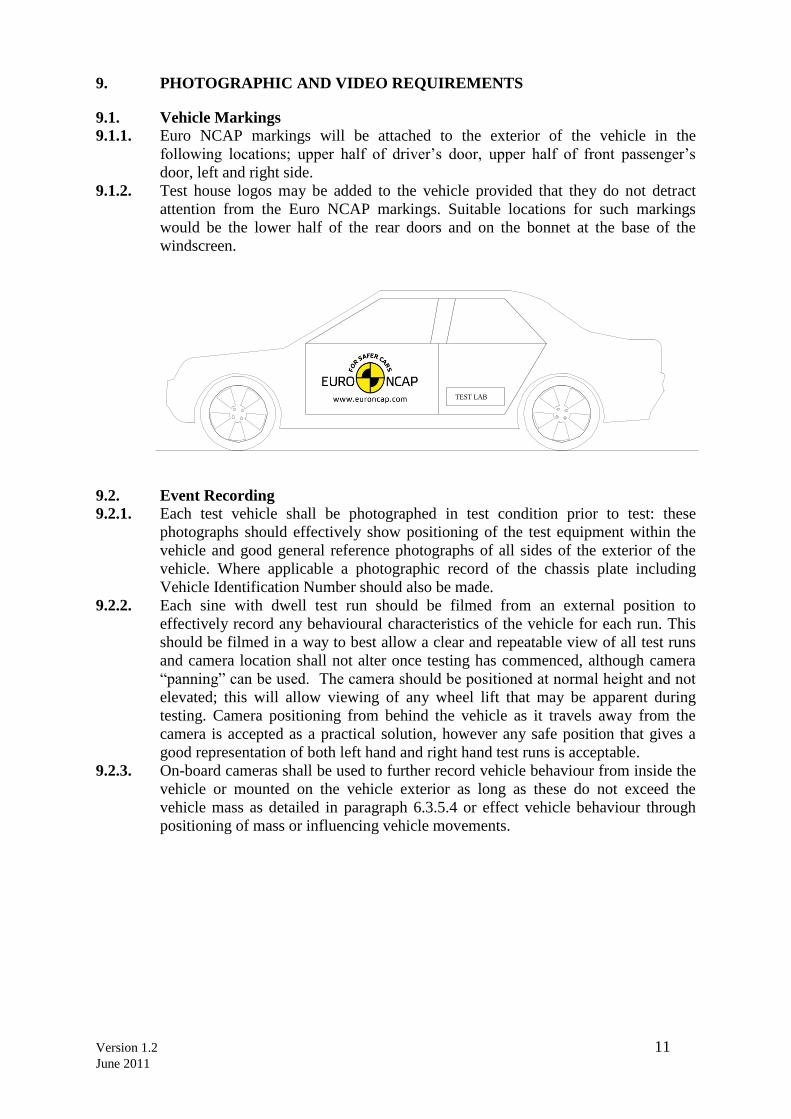
9.1.1. Euro NCAP markings will be attached to the exterior of the vehicle in the
following locations; upper half of driver‟s door, upper half of front passenger‟s
door, left and right side.
9.1.2. Test house logos may be added to the vehicle provided that they do not detract
attention from the Euro NCAP markings. Suitable locations for such markings
would be the lower half of the rear doors and on the bonnet at the base of the
windscreen.
TEST LAB
9.2. Event Recording
9.2.1. Each test vehicle shall be photographed in test condition prior to test: these
photographs should effectively show positioning of the test equipment within the
vehicle and good general reference photographs of all sides of the exterior of the
vehicle. Where applicable a photographic record of the chassis plate including
Vehicle Identification Number should also be made.
9.2.2. Each sine with dwell test run should be filmed from an external position to
effectively record any behavioural characteristics of the vehicle for each run. This
should be filmed in a way to best allow a clear and repeatable view of all test runs
and camera location shall not alter once testing has commenced, although camera
“panning” can be used. The camera should be positioned at normal height and not
elevated; this will allow viewing of any wheel lift that may be apparent during
testing. Camera positioning from behind the vehicle as it travels away from the
camera is accepted as a practical solution, however any safe position that gives a
good representation of both left hand and right hand test runs is acceptable.
9.2.3. On-board cameras shall be used to further record vehicle behaviour from inside the
vehicle or mounted on the vehicle exterior as long as these do not exceed the
vehicle mass as detailed in paragraph 6.3.5.4 or effect vehicle behaviour through
positioning of mass or influencing vehicle movements.
Version 1.2 12
June 2011
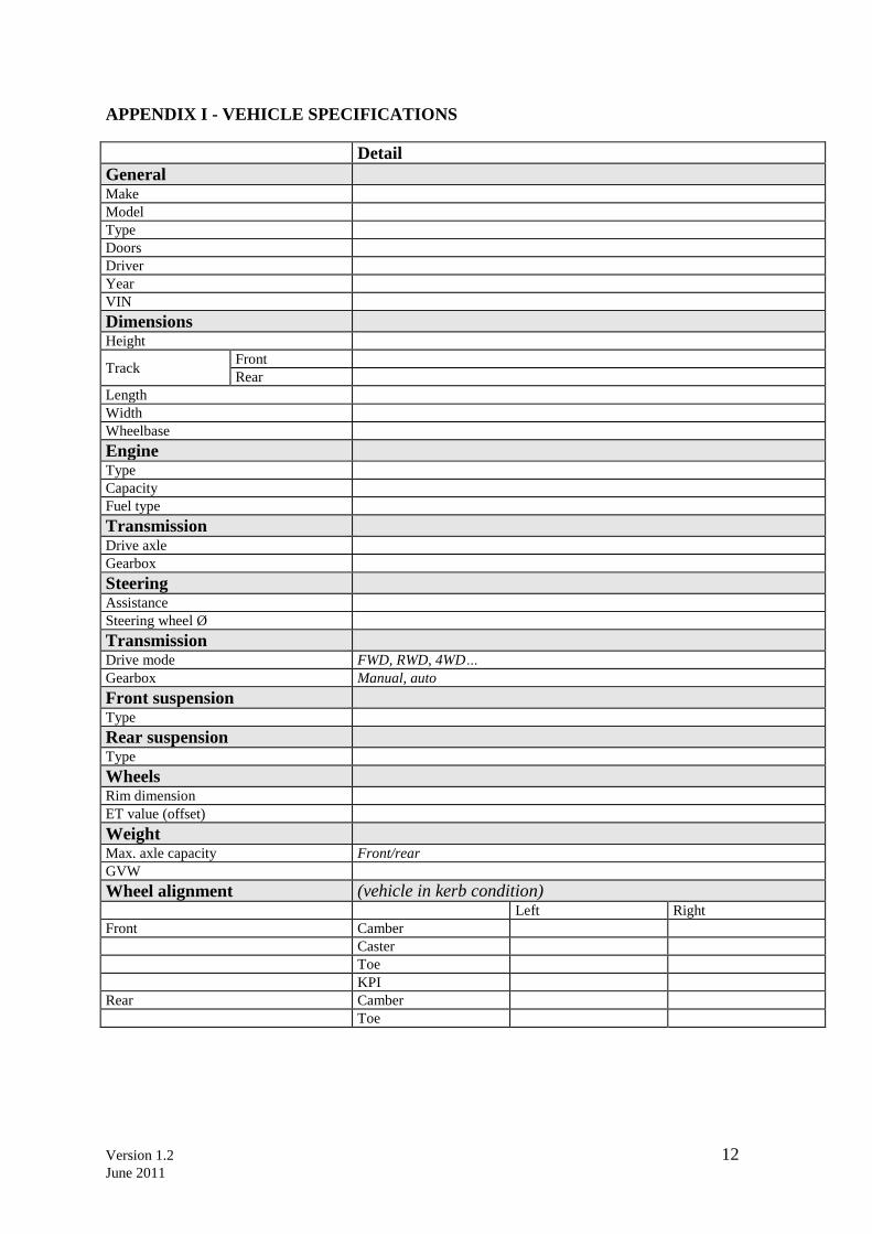
APPENDIX I - VEHICLE SPECIFICATIONS
Detail
General Make
Model
Type
Doors
Driver
Year
VIN
Dimensions Height
Track Front
Rear
Length
Width
Wheelbase
Engine Type
Capacity
Fuel type
Transmission Drive axle
Gearbox
Steering Assistance
Steering wheel Ø
Transmission Drive mode FWD, RWD, 4WD…
Gearbox Manual, auto
Front suspension Type
Rear suspension Type
Wheels Rim dimension
ET value (offset)
Weight Max. axle capacity Front/rear
GVW
Wheel alignment (vehicle in kerb condition) Left Right
Front Camber
Caster
Toe
KPI
Rear Camber
Toe
Version 1.2 13
June 2011
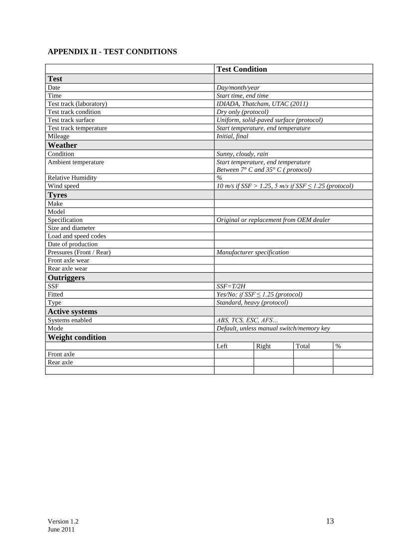
APPENDIX II - TEST CONDITIONS
Test Condition
Test Date Day/month/year
Time Start time, end time
Test track (laboratory) IDIADA, Thatcham, UTAC (2011)
Test track condition Dry only (protocol)
Test track surface Uniform, solid-paved surface (protocol)
Test track temperature Start temperature, end temperature
Mileage Initial, final
Weather Condition Sunny, cloudy, rain
Ambient temperature Start temperature, end temperature
Between 7° C and 35° C ( protocol)
Relative Humidity %
Wind speed 10 m/s if SSF > 1.25, 5 m/s if SSF ≤ 1.25 (protocol)
Tyres Make
Model
Specification Original or replacement from OEM dealer
Size and diameter
Load and speed codes
Date of production
Pressures (Front / Rear) Manufacturer specification
Front axle wear
Rear axle wear
Outriggers SSF SSF=T/2H
Fitted Yes/No; if SSF ≤ 1.25 (protocol)
Type Standard, heavy (protocol)
Active systems Systems enabled ABS, TCS, ESC, AFS…
Mode Default, unless manual switch/memory key
Weight condition Left Right Total %
Front axle
Rear axle
Version 1.2 14
June 2011
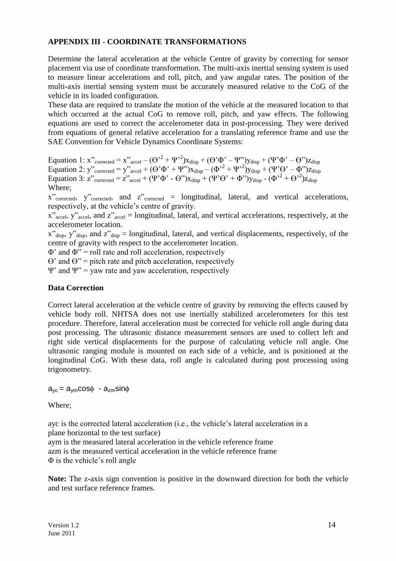
APPENDIX III - COORDINATE TRANSFORMATIONS
Determine the lateral acceleration at the vehicle Centre of gravity by correcting for sensor
placement via use of coordinate transformation. The multi-axis inertial sensing system is used
to measure linear accelerations and roll, pitch, and yaw angular rates. The position of the
multi-axis inertial sensing system must be accurately measured relative to the CoG of the
vehicle in its loaded configuration.
These data are required to translate the motion of the vehicle at the measured location to that
which occurred at the actual CoG to remove roll, pitch, and yaw effects. The following
equations are used to correct the accelerometer data in post-processing. They were derived
from equations of general relative acceleration for a translating reference frame and use the
SAE Convention for Vehicle Dynamics Coordinate Systems:
Equation 1: x”corrected = x”accel – (Ө‟2 + Ψ‟
2)xdisp + (Ө‟Φ‟ – Ψ”)ydisp + (Ψ‟Φ‟ – Ө”)zdisp
Equation 2: y”corrected = y”accel + (Ө‟Φ‟ + Ψ”)xdisp – (Φ‟2 + Ψ‟
2)ydisp + (Ψ‟Ө‟ – Φ”)zdisp
Equation 3: z”corrected = z”accel + (Ψ‟Φ‟ - Ө”)xdisp + (Ψ‟Ө‟ + Φ”)ydisp - (Φ‟2 + Ө‟
2)zdisp
Where;
x”corrected, y”corrected, and z”corrected = longitudinal, lateral, and vertical accelerations,
respectively, at the vehicle‟s centre of gravity.
x”accel, y”accel, and z”accel = longitudinal, lateral, and vertical accelerations, respectively, at the
accelerometer location.
x”disp, y”disp, and z”disp = longitudinal, lateral, and vertical displacements, respectively, of the
centre of gravity with respect to the accelerometer location.
Φ‟ and Φ” = roll rate and roll acceleration, respectively
Ө‟ and Ө” = pitch rate and pitch acceleration, respectively
Ψ‟ and Ψ” = yaw rate and yaw acceleration, respectively
Data Correction
Correct lateral acceleration at the vehicle centre of gravity by removing the effects caused by
vehicle body roll. NHTSA does not use inertially stabilized accelerometers for this test
procedure. Therefore, lateral acceleration must be corrected for vehicle roll angle during data
post processing. The ultrasonic distance measurement sensors are used to collect left and
right side vertical displacements for the purpose of calculating vehicle roll angle. One
ultrasonic ranging module is mounted on each side of a vehicle, and is positioned at the
longitudinal CoG. With these data, roll angle is calculated during post processing using
trigonometry.
ayc = aymcos - azmsin
Where;
ayc is the corrected lateral acceleration (i.e., the vehicle‟s lateral acceleration in a
plane horizontal to the test surface)
aym is the measured lateral acceleration in the vehicle reference frame
azm is the measured vertical acceleration in the vehicle reference frame
Φ is the vehicle‟s roll angle
Note: The z-axis sign convention is positive in the downward direction for both the vehicle
and test surface reference frames.

Version 1.2 15
June 2011
APPENDIX IV – REFERENCES
1. Global Technical Regulation No.8 - Electronic Stability Control Systems, Established in
the Global Registry on 26 June 2008
2. ECE Regulation No. 13-H - Uniform Provisions Concerning the Approval of Passenger
Cars With Regard To Braking, Revision 2, including the amendments which entered into
force on 16 October 1995.


![INDEX [sites.rootsweb.com]sites.rootsweb.com/~scoconee/Cemetery_GPS/surnames/...INDEX Abbott, Alice, 198 Ackerman, Callie Robinson, 540 Ackerman, David, 215 Ackerman, Joseph Earle,](https://static.fdocuments.in/doc/165x107/5e4d824abd5273468b45391f/index-sites-sites-scoconeecemeterygpssurnames-index-abbott-alice-198.jpg)

