European Commission Seventh Framework Programme MODSafe ... · V0. 1 28 -01-2012 Balázs Sághi New...
52
European Commission Seventh Framework Programme MODSafe Modular Urban Transport Safety and Security Analysis Acceptance, Approval, Certification Proposal for a generic AAC process (guidance for case to case adaptation) Deliverable No.D7.4
Transcript of European Commission Seventh Framework Programme MODSafe ... · V0. 1 28 -01-2012 Balázs Sághi New...
European Commission Seventh Framework Programme
MODSafe Modular Urban Transport Safety and Security Analysis
Acceptance, Approval, Certification
Proposal for a generic AAC process (guidance for case to case adaptation)
Deliverable No.D7.4
Doc Name: Deliverable D7.4 Version 1.0 Date: 27-08-2012 ID: DEL_D7.4_BME_WP7_270812_V1.0 Revision: V1.0 Page 2/52
Contract No. 218606
Document type DEL
Version V1.0
Status Final
Date 27-08-2012
WP WP 7
Lead Author Balázs Sághi BME
Contributors TRIT (chapter 6, 7), RATP, LU, R&B, UITP
Description Deliverable D7.4 Version 1.0
Document ID DEL_D7.4_BME_WP7_270812_V1.0
Dissemination level PU
Distribution Consortium
Document History:
Version Date Author Modification [very short description]
V0.1 28-01-2012 Balázs Sághi New document: global structure
V0.2 18-05-2012 Balázs Sághi Doc. development
V0.3 01-06-2012 Balázs Sághi Reworked after WP meeting
V0.4 08-06-2012 Balázs Sághi Corrections from LU and TRIT added
V0.5 09-07-2012 Balázs Sághi Corrections after WP10 review
V0.6 30-07-2012 Balázs Sághi Corrections, submit to WP10
V0.7 22-08-2012 Balázs Sághi Correction after WP10 review
V1.0 24-08-2012 Balázs Sághi Final version
Approval:
Authority Name/Partner Date
WP responsible BME / WP7 Consensus 11-08-2012
EB members WP10 Consensus 24-08-2012
Coordinator TRIT 27-08-2012
Doc Name: Deliverable D7.4 Version 1.0 Date: 27-08-2012 ID: DEL_D7.4_BME_WP7_270812_V1.0 Revision: V1.0 Page 3/52
Table of Contents 1 Introduction .............................................................................................................. 5
1.1 Standardisation programme in the field of Urban Rail .............................................. 6
1.2 References .............................................................................................................. 7
1.3 Terms and Definitions ............................................................................................. 9
1.4 Abbreviations .........................................................................................................11
2 Methodological background ..................................................................................13
2.1 Method of work package 7 .....................................................................................13
2.2 Summary of the results of preceding tasks .............................................................14
2.3 Relation to other work packages ............................................................................19
2.4 Method of deliverable D7.4 .....................................................................................21
3 Proposal for generic roles and responsibilities ...................................................22
3.1 Safety Authority generic role and responsibility ......................................................22
3.1.1 Legal Basis .....................................................................................................22
3.1.2 Generic role and responsibility ........................................................................23
3.1.3 Typical Authority activities in the AAC process ................................................25
3.2 Operator generic role and responsibility .................................................................26
3.2.1 Legal Basis .....................................................................................................26
3.2.2 Generic role and responsibility ........................................................................26
3.2.3 Typical Operator activities in the AAC process ................................................26
3.3 Independent Safety Assessor generic role and responsibility .................................27
3.3.1 Legal Basis .....................................................................................................28
3.3.2 Generic role and responsibility ........................................................................28
3.3.3 Independent Safety Assessment Methodology ................................................29
3.3.4 Typical Independent Safety Assessor activities in the AAC process ................32
3.4 Supplier(s) generic role and responsibility ..............................................................32
3.4.1 Legal Basis .....................................................................................................32
3.4.2 Generic role and responsibility ........................................................................33
3.4.3 Typical Supplier activities in the AAC process .................................................33
4 Proposal of a core process ....................................................................................34
5 Adapting the core AAC process ............................................................................38
5.1 Size of the system ..................................................................................................38
5.2 Complexity of the system .......................................................................................38
5.3 Level of safety ........................................................................................................41
5.4 Nature of the project ...............................................................................................44
5.5 Grade of Automation ..............................................................................................46

Doc Name: Deliverable D7.4 Version 1.0 Date: 27-08-2012 ID: DEL_D7.4_BME_WP7_270812_V1.0 Revision: V1.0 Page 4/52
5.6 Type of system (tram/ light rail / metro) ..................................................................46
6 Cross acceptance ...................................................................................................48
6.1 Criteria for Cross-Acceptance ................................................................................48
6.2 Depth of a safety assessment ................................................................................49
6.3 Process for cross-acceptance ................................................................................51
7 Conclusion ..............................................................................................................52
List of Figures Figure 1 – Work process of WP7 ..........................................................................................13 Figure 2 – System of EAMs [MODSafe D7.2] .......................................................................16 Figure 3 – Relationship to MODSafe Deliverables ................................................................20 Figure 4 – Generic Legislation Pyramid ................................................................................23 Figure 5 – Independent Safety Assessor involvement ..........................................................29 Figure 6 – Independence and combination of roles versus Safety Integrity Levels. Based on [prEN50126]. ........................................................................................................................42 Figure 7 – Depth of the safety assessment ...........................................................................50 Figure 8 – Example of cross-acceptance process ................................................................51 List of Tables Table 1 – Generic allocation of EAMs to participants [MODSafe D7.3] .................................18 Table 2 – EAMs with fixed allocation ....................................................................................34 Table 3 – EAMs with variable allocation ...............................................................................35 Table 4 – Optional EAMs ......................................................................................................35 Table 5 – Proposal for core AAC process .............................................................................36
Doc Name: Deliverable D7.4 Version 1.0 Date: 27-08-2012 ID: DEL_D7.4_BME_WP7_270812_V1.0 Revision: V1.0 Page 5/52
1 Introduction
In Europe, Light Rail, Metros and Trams – altogether Urban Guided Transport – are characterised by a diversified landscape of safety requirements, safety models, roles and responsibilities, schemes for safety acceptance and approval; however, there are convergences between some architectures and systems, [MODUrban D9.3]. There are currently no standardised procedures at the European level for bringing Urban Guided Transport into service. There are no common standard procedures in Europe for safety evaluation (each country applies its own safety conformity assessment). Recent applications have been increasingly assessed by taking into account the European standards EN 50126/50128/50129, [CENELEC]. Numerous Urban Guided Transport stakeholders believe that the development of European (and even worldwide) standards should be encouraged, in order to facilitate the voluntary reference to such standards by relevant national authorities and the various stakeholders, [MODUrban D9.3]. The European Commission is favouring this approach, notably through its support of major European research projects such as the MODSafe project. The Acceptance, Approval and Certification (AAC) procedures are characterised by high diversity in different European countries. Diverse actors are involved and different procedures and different roles are applied along the AAC course in the field of Urban Guided Transport systems, which are non-interoperable with other rail systems and are rarely needed for interconnectivity with another rail system (e.g. tram-train). The diversity relates also to functional and safety requirements, safety models. The diversity also includes certain situations, in which there is no national or local obligation for certification at all. However according to [MODURBAN D9.3] some synergies can be observed in this field. This work package focuses on one hand on Metros, Light Rail Systems, and Trams, covering the whole transportation system including all sub-systems, e.g. signalling system or rolling stock. Heavy rail and urban commuter trains like “S-Bahn” in Germany or SNCF “RER” in France are not within the focus. The work package 7 focuses on the other hand on acceptance, approval and certification, i.e. it deals with activities, the sequence of which is closed by putting the system into passenger service. Regulatory and supervisory activities after putting into service are not in the scope of this work package. However, these activities are important to ensure safe operation and are discussed within work package 6. The term authority in this deliverable always means safety authority, the function of which is to state that a safety-related system is fit for service and complies with relevant statutory and regulatory safety requirements, according to EN 50129 [CENELEC]. The term supervisory authority refers to a body entrusted with the tasks regarding supervision of the operation and maintenance of Urban Guided Transport systems (i.e. with tasks after putting into service). The supervisory authority and the safety authority is often the same organisation. In some cases the safety authority allows the operator to act as its own safety authority under certain conditions (e.g. in UK, ORR as the Safety Authority for UK allows London

Doc Name: Deliverable D7.4 Version 1.0 Date: 27-08-2012 ID: DEL_D7.4_BME_WP7_270812_V1.0 Revision: V1.0 Page 6/52
Underground to act as its own safety authority and approve its own changes as long as an approved Safety Management System and a Safety Certificate from the ORR is available. London Underground also acts as the supervisory authority as it monitors safety of the system after it has been put into passenger service). The main objective of the work package 7 within this EU-funded MODSafe project is to make the diversity transparent for participants of these processes (Operators, Suppliers etc.) by developing and proposing a generic framework for the AAC procedures, which is based on elementary activity modules and on an analysis of current AAC procedures across Europe. The output of this deliverable is a proposal for a generic AAC process and further guidance on how to adapt that generic process for specific situations.
1.1 Standardisation programme in the field of Urban Rail
The mandate M/486 on programming and standardisation in the field of Urban Rail states that: “As the essential requirements set out in Annex III of the Interoperability Directive 2008/57/EC [2008/57/EC] were not intended to cover urban and local rail systems and even if a majority of those essential requirements are applicable as well to urban and local rail systems due to the fact that they were expressed in very generic terms, there is a need to assess the essential requirements of the interoperability directive against the scope of this mandate.” The mandate committed the representative rail associations of the sector UITP and UNIFE (coordinated through their joint Urban Rail Platform, URP) to define “a set of “fundamental requirements” to be used as a basic reference for the execution of this mandate.” The URP document “Fundamental requirements for Urban Rail systems design, construction, manufacture, operations & maintenance” [URP-FR] published in English, German and French on 5th of October 2011 was acknowledged by the European Commission on 24st November 2011 and put on the website dedicated to the information of Member States representatives in the Railway Interoperability and Safety Committee (“RISC”). It is a reference for all future works regarding standardisation in the field of Urban Rail. CEN TC256 and CENELEC TC9X have decided to transfer the “Fundamental requirements” into a reference standard through a “Unique Approval Process” keeping the text unchanged, in order to officialise the document in a more visible way. The process is underway.

Doc Name: Deliverable D7.4 Version 1.0 Date: 27-08-2012 ID: DEL_D7.4_BME_WP7_270812_V1.0 Revision: V1.0 Page 7/52
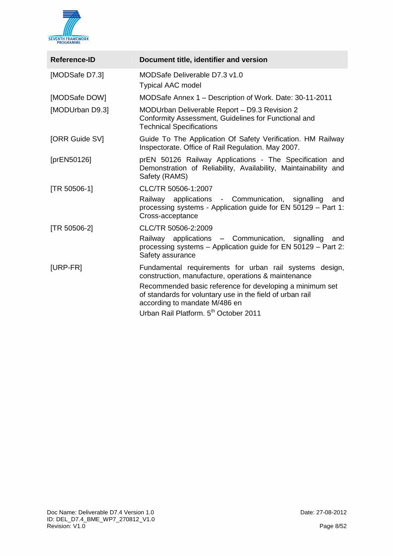
1.2 References
Reference-ID Document title, identifier and version
[2008/57/EC] Directive 2008/57/EC of the European Parliament and of the Council of 17 June 2008 on the interoperability of the rail system within the Community
[CENELEC] EN 50126:1999 "Railway applications - The specification and demonstration of Reliability, Availability, Maintainability and Safety (RAMS)"
EN 50128:2011 “Railway applications -
Communications, signalling and processing systems -
Software for railway control and protection systems"
EN 50129:2003 “Railway applications -
Communication, signalling and processing systems -
Safety related electronic systems for signalling”
[EN 45011] EN 45011:2008 General requirements for bodies operating product certification systems
[EN ISO/IEC 17020] EN ISO/IEC 17020:2004 General criteria for the operation of various types of bodies performing inspection
[Glossary.en] MODSafe Glossary - Deliverable D10.5
[IRSE-Rep.6] Proposed Cross Acceptance Processes for Railway Signalling Systems and Equipment. Institution of Railway Signal Engineers. International Technical Committee. 6th report.
[MODSafe D1.2] MODSafe Deliverable D1.2 v3
State of the art on Safety Responsibilities and Certification
[MODSafe D4.2] MODSafe Deliverable D4.2 v2.0
Analysis of Safety Requirements for MODSafe Continuous Safety Measures and Functions
[MODSafe D4.3] MODSafe Deliverable D4.2 v1.3
Analysis of On-Demand Functions
[MODSafe D6.1] MODSafe Deliverable D6.1 v1.0
Survey of current safety lifecycle approaches
[MODSafe D6.2] MODSafe Deliverable D6.2 v1.0
Comparison of current safety lifecycle approaches
[MODSafe D6.3] MODSafe Deliverable D6.3 v1.0
Proposal of a common safety life cycle approach
[MODSafe D7.1] MODSafe Deliverable D7.1 v1.0
Survey of Current AAC procedures
[MODSafe D7.2] MODSafe Deliverable D7.2 v1.0
List of elementary activity modules
Doc Name: Deliverable D7.4 Version 1.0 Date: 27-08-2012 ID: DEL_D7.4_BME_WP7_270812_V1.0 Revision: V1.0 Page 8/52
Reference-ID Document title, identifier and version
[MODSafe D7.3] MODSafe Deliverable D7.3 v1.0
Typical AAC model
[MODSafe DOW] MODSafe Annex 1 – Description of Work. Date: 30-11-2011
[MODUrban D9.3] MODUrban Deliverable Report – D9.3 Revision 2 Conformity Assessment, Guidelines for Functional and Technical Specifications
[ORR Guide SV] Guide To The Application Of Safety Verification. HM Railway Inspectorate. Office of Rail Regulation. May 2007.
[prEN50126] prEN 50126 Railway Applications - The Specification and Demonstration of Reliability, Availability, Maintainability and Safety (RAMS)
[TR 50506-1] CLC/TR 50506-1:2007
Railway applications - Communication, signalling and processing systems - Application guide for EN 50129 – Part 1: Cross-acceptance
[TR 50506-2] CLC/TR 50506-2:2009
Railway applications – Communication, signalling and processing systems – Application guide for EN 50129 – Part 2: Safety assurance
[URP-FR] Fundamental requirements for urban rail systems design, construction, manufacture, operations & maintenance
Recommended basic reference for developing a minimum set of standards for voluntary use in the field of urban rail according to mandate M/486 en
Urban Rail Platform. 5th October 2011
Doc Name: Deliverable D7.4 Version 1.0 Date: 27-08-2012 ID: DEL_D7.4_BME_WP7_270812_V1.0 Revision: V1.0 Page 9/52
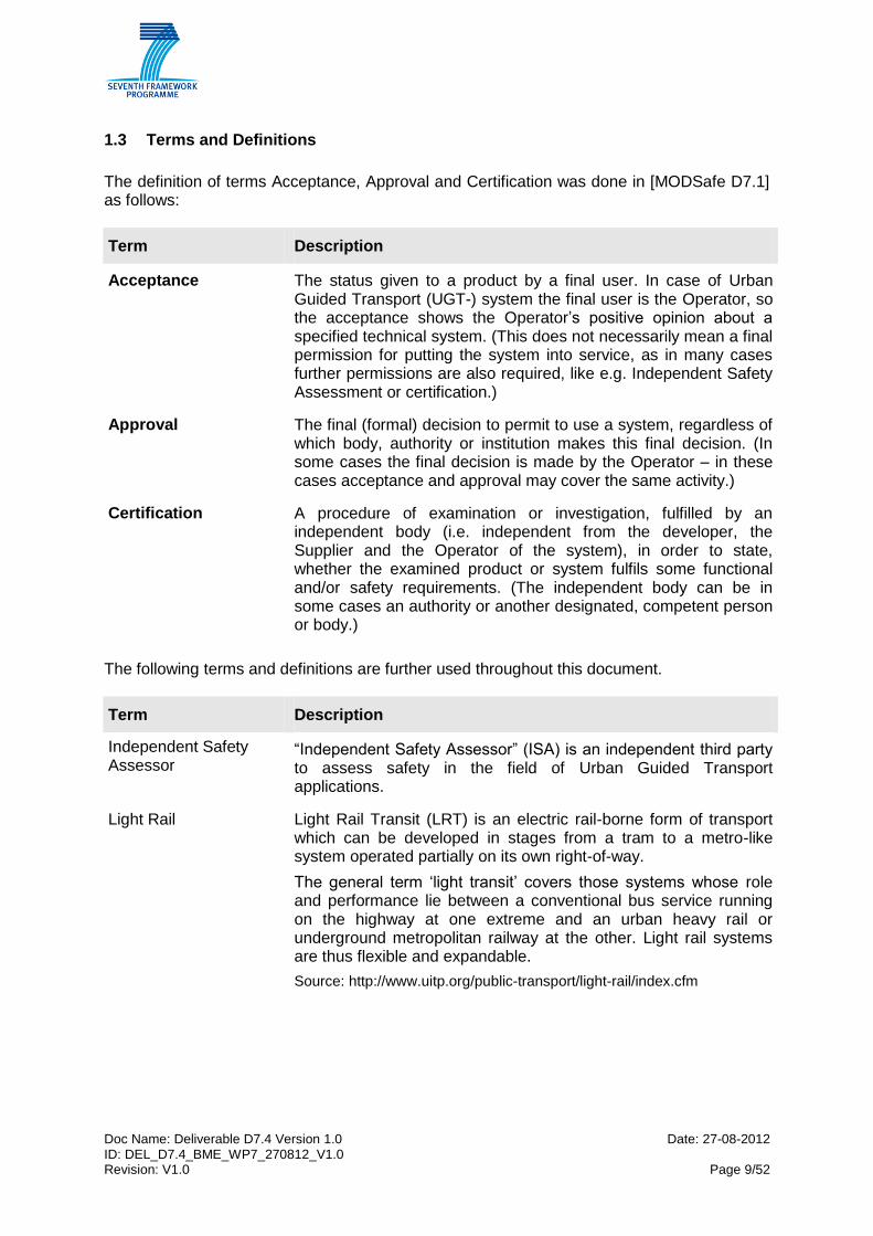
1.3 Terms and Definitions
The definition of terms Acceptance, Approval and Certification was done in [MODSafe D7.1] as follows:
Term Description
Acceptance The status given to a product by a final user. In case of Urban Guided Transport (UGT-) system the final user is the Operator, so the acceptance shows the Operator’s positive opinion about a specified technical system. (This does not necessarily mean a final permission for putting the system into service, as in many cases further permissions are also required, like e.g. Independent Safety Assessment or certification.)
Approval The final (formal) decision to permit to use a system, regardless of which body, authority or institution makes this final decision. (In some cases the final decision is made by the Operator – in these cases acceptance and approval may cover the same activity.)
Certification A procedure of examination or investigation, fulfilled by an independent body (i.e. independent from the developer, the Supplier and the Operator of the system), in order to state, whether the examined product or system fulfils some functional and/or safety requirements. (The independent body can be in some cases an authority or another designated, competent person or body.)
The following terms and definitions are further used throughout this document.
Term Description
Independent Safety Assessor
“Independent Safety Assessor” (ISA) is an independent third party to assess safety in the field of Urban Guided Transport applications.
Light Rail Light Rail Transit (LRT) is an electric rail-borne form of transport which can be developed in stages from a tram to a metro-like system operated partially on its own right-of-way.
The general term ‘light transit’ covers those systems whose role and performance lie between a conventional bus service running on the highway at one extreme and an urban heavy rail or underground metropolitan railway at the other. Light rail systems are thus flexible and expandable.
Source: http://www.uitp.org/public-transport/light-rail/index.cfm
Doc Name: Deliverable D7.4 Version 1.0 Date: 27-08-2012 ID: DEL_D7.4_BME_WP7_270812_V1.0 Revision: V1.0 Page 10/52
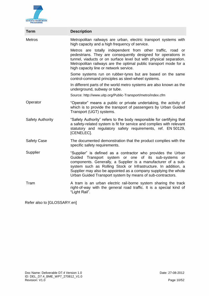
Term Description
Metros Metropolitan railways are urban, electric transport systems with high capacity and a high frequency of service.
Metros are totally independent from other traffic, road or pedestrians. They are consequently designed for operations in tunnel, viaducts or on surface level but with physical separation. Metropolitan railways are the optimal public transport mode for a high capacity line or network service.
Some systems run on rubber-tyres but are based on the same control-command principles as steel-wheel systems.
In different parts of the world metro systems are also known as the underground, subway or tube.
Source: http://www.uitp.org/Public-Transport/metro/index.cfm
Operator
“Operator” means a public or private undertaking, the activity of which is to provide the transport of passengers by Urban Guided Transport (UGT) systems.
Safety Authority
“Safety Authority” refers to the body responsible for certifying that a safety-related system is fit for service and complies with relevant statutory and regulatory safety requirements, ref. EN 50129, [CENELEC].
Safety Case The documented demonstration that the product complies with the specific safety requirements.
Supplier
“Supplier” is defined as a contractor who provides the Urban Guided Transport system or one of its sub-systems or components. Generally, a Supplier is a manufacturer of a sub-system such as Rolling Stock or Infrastructure. In addition, a Supplier may also be appointed as a company supplying the whole Urban Guided Transport system by means of sub-contractors.
Tram A tram is an urban electric rail-borne system sharing the track right-of-way with the general road traffic. It is a special kind of “Light Rail”.
Refer also to [GLOSSARY.en]
Doc Name: Deliverable D7.4 Version 1.0 Date: 27-08-2012 ID: DEL_D7.4_BME_WP7_270812_V1.0 Revision: V1.0 Page 11/52
1.4 Abbreviations
In addition, the following abbreviations are used in this document:
Abbreviation Explanation
AAC Acceptance, Approval, Certification
ALARP As Low As Reasonably Practicable
AOT Autorité Organisatrice de Transport Transport Organising Authority (in France)
ASR, ASSR Assessor
BOT Build-Operate-Transfer
CCTV Closed Circuit Television
D Germany
DES Designer
EAM Elementary Activity Module
EU European Union
F France
GAME Globalement Au Moins Equivalent (Globally at least equivalent)
GOA Grade of Automation
H Hungary
IMP Implementer
INT Integrator
ISA Independent Safety Assessor
LRT Light Rail Transit
LU London Underground
MODSafe Modular Urban Transport Safety and Security Analysis
MODUrban Modular Urban Guided Rail System project
PJM Project Manager
PM Project Management
PPP Public-Private-Partnership
RAMS Reliability, Availability, Maintainability and Safety
REQ Requirements Manager
RISC Railway Interoperability and Safety Committee
S Sweden
SIL Safety Integrity Level
SNCF Société nationale des chemins de fer français
TFFR Tolerable Functional Failure Rate
TST Tester
UGT Urban Guided Transport
UITP International Association of Public Transport

Doc Name: Deliverable D7.4 Version 1.0 Date: 27-08-2012 ID: DEL_D7.4_BME_WP7_270812_V1.0 Revision: V1.0 Page 12/52
Abbreviation Explanation
UK United Kingdom
UNIFE Association of the European Rail Industry
URP Urban Rail Platform (UITP-UNIFE coordination body for Urban Rail)
V&V Verification and Validation
VAL Validator
VER Verifier
WP Work Package
Doc Name: Deliverable D7.4 Version 1.0 Date: 27-08-2012 ID: DEL_D7.4_BME_WP7_270812_V1.0 Revision: V1.0 Page 13/52
2 Methodological background
2.1 Method of work package 7
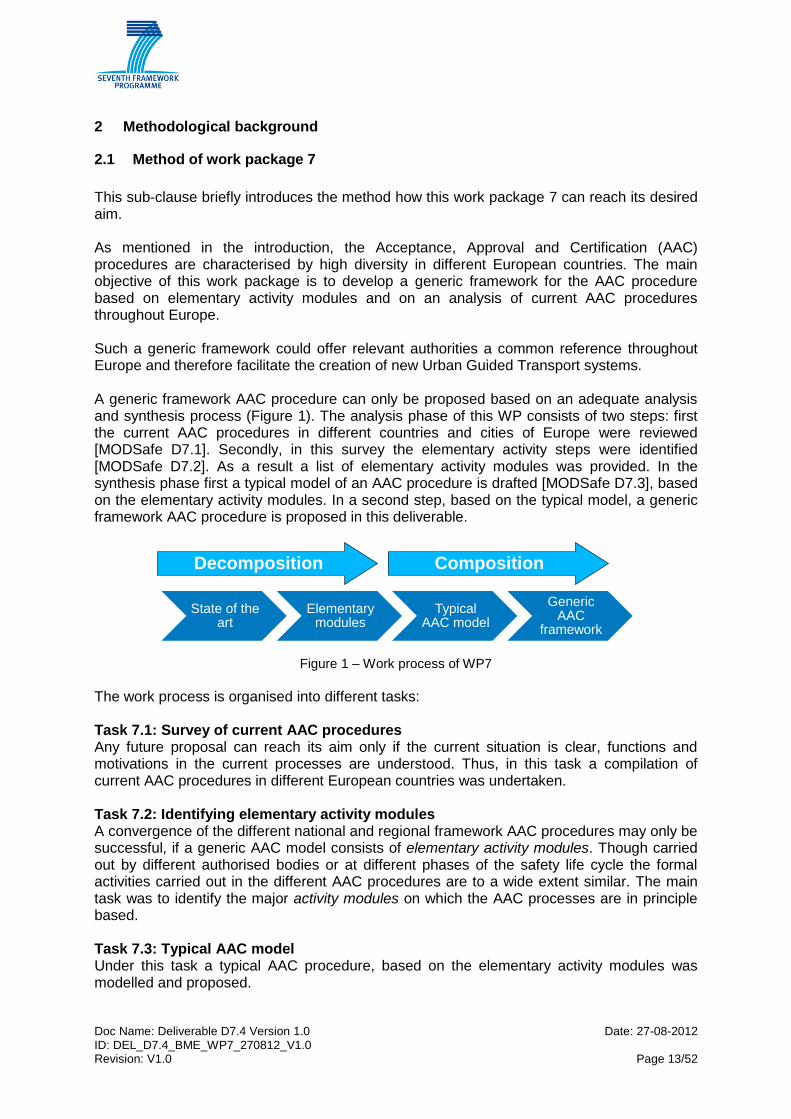
This sub-clause briefly introduces the method how this work package 7 can reach its desired aim. As mentioned in the introduction, the Acceptance, Approval and Certification (AAC) procedures are characterised by high diversity in different European countries. The main objective of this work package is to develop a generic framework for the AAC procedure based on elementary activity modules and on an analysis of current AAC procedures throughout Europe. Such a generic framework could offer relevant authorities a common reference throughout Europe and therefore facilitate the creation of new Urban Guided Transport systems. A generic framework AAC procedure can only be proposed based on an adequate analysis and synthesis process (Figure 1). The analysis phase of this WP consists of two steps: first the current AAC procedures in different countries and cities of Europe were reviewed [MODSafe D7.1]. Secondly, in this survey the elementary activity steps were identified [MODSafe D7.2]. As a result a list of elementary activity modules was provided. In the synthesis phase first a typical model of an AAC procedure is drafted [MODSafe D7.3], based on the elementary activity modules. In a second step, based on the typical model, a generic framework AAC procedure is proposed in this deliverable.
State of the art
Elementary modules
TypicalAAC model
GenericAAC
framework
Decomposition Composition
Figure 1 – Work process of WP7
The work process is organised into different tasks: Task 7.1: Survey of current AAC procedures Any future proposal can reach its aim only if the current situation is clear, functions and motivations in the current processes are understood. Thus, in this task a compilation of current AAC procedures in different European countries was undertaken. Task 7.2: Identifying elementary activity modules A convergence of the different national and regional framework AAC procedures may only be successful, if a generic AAC model consists of elementary activity modules. Though carried out by different authorised bodies or at different phases of the safety life cycle the formal activities carried out in the different AAC procedures are to a wide extent similar. The main task was to identify the major activity modules on which the AAC processes are in principle based. Task 7.3: Typical AAC model Under this task a typical AAC procedure, based on the elementary activity modules was modelled and proposed.
Doc Name: Deliverable D7.4 Version 1.0 Date: 27-08-2012 ID: DEL_D7.4_BME_WP7_270812_V1.0 Revision: V1.0 Page 14/52
Task 7.4: Proposal for a generic AAC process (guidance for case to case adaptation) (current task) Based on the survey and based on typical model of AAC processes a generic AAC process is proposed which serve as a framework for AAC processes. The generic AAC process consists of a core process and of guidance or toolbox for case-to-case adaptation. This method enables adaptation of the AAC processes for specific application cases, thus allowing optimal organisation (with respect to time and cost aspects) of processes for specific cases.
2.2 Summary of the results of preceding tasks
In task 7.1 a survey was undertaken in order to collect data about the current acceptance, approval and certification processes used in different countries of Europe in the field of Urban Guided Transport systems. For this a questionnaire was used, which was elaborated in work package 6, task 6.1. From this questionnaire the relevant questions and answers were selected and analysed. As an outcome of the analysis the following results were gained:
Definition of the terms acceptance, approval and certification
Identification of the main participants of the approval, acceptance and certification processes.
In task 7.2 the work was continued in order to identify the so-called elementary activity modules (EAM). The elementary activity modules (EAM) are activities that are identical in approval, acceptance and certification processes of different countries, but they may be carried out by different parties with different levels of independence, and possibly at different stages of the system life cycle. EAMs were identified by comparing the different procedures of different countries or cities. In order for the comparison to deliver adequate results, the different processes were described in the same way. As a result of this comparison of different description methods, cross functional flowcharts were selected as a common description. After finishing the task 7.1 it became clear that a whole and complete European survey with such details that enable the identification of EAMs was not possible within this work package. Therefore it was decided to select a possible representative sample of countries, which were analysed in more detail. Using the cross functional flowcharts, the following case studies were elaborated in more detail:
France,
Germany,
Hungary,
Sweden,
United Kingdom (London Underground).

Doc Name: Deliverable D7.4 Version 1.0 Date: 27-08-2012 ID: DEL_D7.4_BME_WP7_270812_V1.0 Revision: V1.0 Page 15/52
After the analysis and comparison of the processes, described in detail in the case studies, similar activities were found. These are the activities that were defined as Elementary Activity Modules. These are elementary parts of the processes. In [MODSafe D7.2] the following EAMs were identified (grouped according to system hierarchy level):
System level o Definition of system requirements o Check of system requirements o Demonstration of fulfilment of system requirements, test operation o Check of fulfilment of system requirements o Approval
Functional level o Definition of functional requirements o Check of functional requirements o Demonstration of fulfilment of functional requirements o Check of fulfilment of functional requirements
Safety level o Definition of safety requirements o Check of safety requirements o Demonstration of fulfilment of safety requirements o Check of fulfilment of safety requirements o Independent Safety Assessment
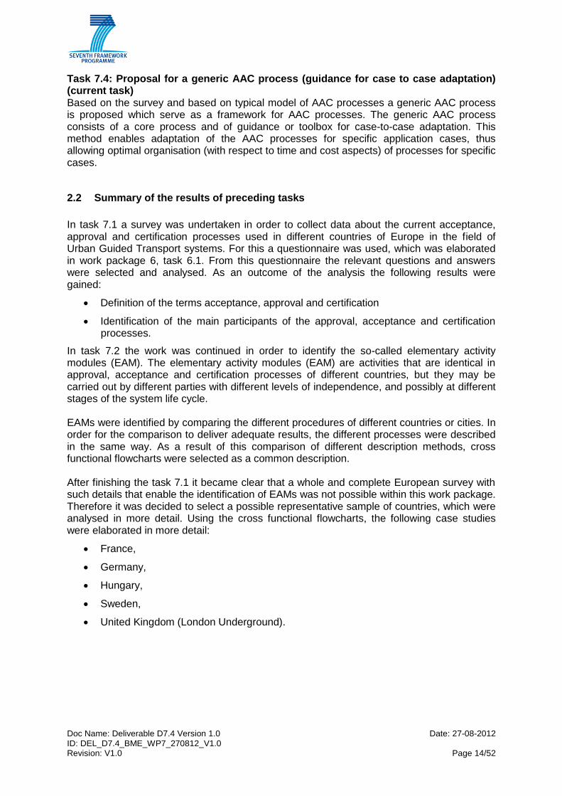
The EAMs were organised according to life cycle phases and the system hierarchy level. The result of this is shown in Figure 2, which is intended to represent the organisation of the EAMs according to these two factors. Furthermore the figure represents information flow between modules. The theoretical process, which is behind Figure 2, is the following: the first AAC activity in a system life cycle is the definition of system requirements, then the functional requirements. The document [URP-FR] provides further guidance to fundamental requirements of urban rail systems, regarding design, construction, manufacture, operations and maintenance. If the system contains safety functions, the safety requirements are also defined. Generally (but not necessarily in every case) the system, functional and safety requirements are checked, whether the definition is correct, complete, adequate etc. The system (sub-system or component) is implemented according to the defined and checked requirements. The next phase in the AAC process is the demonstration of fulfilment of requirements, with respect to safety, functional and system requirements. Generally the demonstration of the fulfilment of requirement is also checked. In case of safety critical systems often an Independent Safety Assessor is also involved to perform the task of the independent safety assessment, which is focusing of safety aspects of the system. The examinations of the assessment can be used during the approval, which is the final act before putting the system into service.
Doc Name: Deliverable D7.4 Version 1.0 Date: 27-08-2012 ID: DEL_D7.4_BME_WP7_270812_V1.0 Revision: V1.0 Page 16/52
SafetySystem Functionality
Check of
functional
requirements
Demonstration of
fulfilment of func.
requirements
Check of fulfilment
of functional
requirements
Check of safety
requirements
Demonstration of
fulfilment of safety
requirements
Definition of safety
requirements
Check of fulfilment
of safety
requirements
Approval
Independent
Safety
Assessment
Hierarchy / downwardsT
ime
/ life
cycle
ph
ase
s
Definition of
system
requirements
Definition of
functional
requirements
Check of system
requirements
Design, implementation
Demo. of fulfilment
of sys reqs/ test
operation
Check of fulfilment
of system
requirements
Figure 2 – System of EAMs [MODSafe D7.2]
Furthermore, the EAMs were linked to specific phases of the life cycle, proposed in [MODSafe D6.3] In task 7.3 a typical AAC model is introduced. The model is based on practical experiences gained from different case studies. It is shown that the Elementary Activity Modules (identified in [MODSafe D7.2]) can be applied for the description of different acceptance, approval and certification processes. Furthermore the EAMs were linked to the participants of AAC processes. The typical processes at different levels of system hierarchy (system, functionality and safety) are described with help of EAMs. The EAMs are allocated to the main participants of acceptance, approval and certification procedures. These participants were identified in [MODSafe D7.1] as follows (some of them are optional):
the Operator,
the Supplier,

Doc Name: Deliverable D7.4 Version 1.0 Date: 27-08-2012 ID: DEL_D7.4_BME_WP7_270812_V1.0 Revision: V1.0 Page 17/52
the Authority,
an Independent Safety Assessor and/or an Independent Certification Body. To determine the linkage of activities to participants a table is used in [MODSafe D7.3], showing all elementary activity modules and all the participants. The sequence of the EAMs follows the timeline of the lifecycle phases. In the table, as it is a generic allocation, only the responsibility is shown (written as “Resp.”). Different practices of different countries (based on the case studies) are also marked (with the abbreviation of the given country). This means that the table contains common practices in Europe as well as differences. Common practices are marked with green background colour in the appropriate cells. The type of allocation is also shown in Table 1 below. This can be a ‘legal obligation’ (resulting from a law or act etc.), it can be originated from a contract or it can be ‘good practice’. If an activity is not common in every country, then it is also remarked.

Doc Name: Deliverable D7.4 Version 1.0 Date: 27-08-2012 ID: DEL_D7.4_BME_WP7_270812_V1.0 Revision: V1.0 Page 18/52
Participant
EAM Type of allocation/ comment
Operator (AOT in France)
Supplier Safety Authority
Independent Safety
Assessor or Certification
Body
Definition of
system
requirements
Legal obligation Resp.
Check of system
requirements
Not common (e.g. not in S)
Resp. (F) Resp. (UK)*** Legal resp.
(D, H) Good practice
resp. (UK)
Definition of
functional
requirements
Legal obligation Resp.
Check of
functional
requirements
Not common (e.g. not in S)
Resp. (F) Resp. (UK)*** Legal resp.
(D, H) Good practice
resp. (UK)
Definition of safety
requirements
Legal obligation Resp.
Check of safety
requirements
Legal obligation Resp. (UK) Resp. (UK)*** Resp. (D, F, H, S)
Good practice resp. (UK)
Demonstration of
fulfilment of safety
requirements
Legal obligation Resp.
Check of fulfilment
of safety
requirements
Legal obligation Resp. (F) Resp. (UK)*** Resp.
(D, F, S) Resp.
(F****, UK, H)
Demonstration of
fulfilment of func.
requirements
Contract Resp.
Check of fulfilment
of functional
requirements
Not common (e.g. not in S)
Resp. (F) Resp. (UK)*** Resp. (D) Resp. (H)
Demo. of fulfilment
of sys reqs/ test
operation
Contract Resp.
(shared)* Resp.
(shared)*
Check of fulfilment
of system
requirements
Contract and/or legal obligation
Resp. (F, H, UK)
Resp. (UK)***
Resp. (D, S)
Resp. (H)
Independent
safety
assessment
Legal obligation or good practice
Resp. (ISA)
Approval
Not always formal
(e.g. Belgium) Resp. (UK)** Resp.
Table 1 – Generic allocation of EAMs to participants [MODSafe D7.3]

Doc Name: Deliverable D7.4 Version 1.0 Date: 27-08-2012 ID: DEL_D7.4_BME_WP7_270812_V1.0 Revision: V1.0 Page 19/52
* the Operator and the Supplier are working together as a project team, which is within the operating company, but they are independent from those responsible for safety approval.
** Operator in the UK acts as Safety Authority (London Underground is – non typically – a subsidiary part of the London Government, what means, that the Operator has the status of a public body.)
*** in UK Project Delivery Team (which is part of the operating company) and Supplier work together and are responsible for check of safety requirements, functional requirements and system requirements
**** in France system parts can sometimes be certified by a certification body Table 1, as introduced in [MODSafe D7.3] plays an important role in the MODSafe task 7.4, the results of which are compiled in this deliverable. Therefore the table is repeated here for better understanding of the current deliverable.
2.3 Relation to other work packages
As described in the [MODSafe DOW], case study results of [MODSafe D1.2] have been used as input for the survey [MODSafe D7.1]. Additionally, opportunities for synergy with WP6 have been exploited, sharing the results with [MODSafe D6.1] and [MODSafe D6.2] due to the fact that Work Packages 6 and 7 have a common base and interdependencies.
The proposal of a generic AAC process [MODSafe D7.4] is based on the elementary activity modules [MODSafe D7.2] and the generic approach of AAC procedures [MODSafe D7.3] and considers the interfaces between the different life cycle approach phases and roles and responsibilities. It also makes use of the generic life cycle approach from [MODSafe D6.3].
The MODSafe safety deliverables of Work Packages 3 – 5 (hazard and risk analysis, hazard control and safety response analysis, common requirements specification, functional / object safety model) are referred to in the respective life cycle approach phases of the proposed common life cycle approach. The process deliverables of Work Packages 6 and 7 as well as the security deliverables of Work Packages 8 and 9 apply throughout the entire life cycle. The relationship to these MODSafe deliverables is shown in the figure below.

Doc Name: Deliverable D7.4 Version 1.0 Date: 27-08-2012 ID: DEL_D7.4_BME_WP7_270812_V1.0 Revision: V1.0 Page 20/52
Figure 3 – Relationship to MODSafe Deliverables

Doc Name: Deliverable D7.4 Version 1.0 Date: 27-08-2012 ID: DEL_D7.4_BME_WP7_270812_V1.0 Revision: V1.0 Page 21/52
2.4 Method of deliverable D7.4
This deliverable has been formulated using the following structure. First a proposal is demonstrated for generic roles and responsibilities of different parties in the acceptance, approval and certification processes (chapter 3). After this a core process is proposed for AAC processes in chapter 4. The core process represents the common practices of different countries. In chapter 5, guidance is provided on how different factors may influence the AAC processes, i.e. their effect on the core process is analysed. Finally, chapter 6 is dedicated to cross acceptance, which plays a central role in AAC processes.
Doc Name: Deliverable D7.4 Version 1.0 Date: 27-08-2012 ID: DEL_D7.4_BME_WP7_270812_V1.0 Revision: V1.0 Page 22/52
3 Proposal for generic roles and responsibilities
The main participants of acceptance, approval and certification processes were identified in [MODSafe D7.1] as follows (some of them are optional):
the Operator,
the Supplier,
the Safety Authority,
an Independent Safety Assessor and/or an Independent Certification Body.
The following chapters provide a brief description of the proposed generic roles and
responsibilities for these participants.
3.1 Safety Authority generic role and responsibility
3.1.1 Legal Basis
Referring to the legislation pyramid as identified in [MODSafe D6.2], a legal basis is / shall be
given in each EU Member State in form of law(s) or act(s) for the handling of urban public
transport / of Urban Guided Transport systems.
This legal basis shall also legally allocate the “safety authority function” to a respective entity
in the Member State, usually to a so-called Safety Authority (for the Urban Guided Transport
sector), acting on behalf of the Member State (or a federal unit thereof).
After successful approval of the Urban Guided Transport system and / or its sub-systems,
the Safety Authority has the responsibility for approving operation.
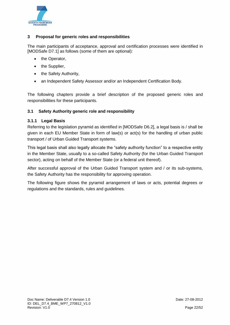
The following figure shows the pyramid arrangement of laws or acts, potential degrees or
regulations and the standards, rules and guidelines.
Doc Name: Deliverable D7.4 Version 1.0 Date: 27-08-2012 ID: DEL_D7.4_BME_WP7_270812_V1.0 Revision: V1.0 Page 23/52
Figure 4 – Generic Legislation Pyramid
To streamline the current European diversity, the legal basis should not specify detailed requirements for Urban Guided Transport systems and its sub-systems. Obligations and requirements of generic nature may be specified in form of underlying (national) degrees or regulations while functional and technical requirements as such should be covered by state of the art (or future European) standards, rules and guidelines on the lowest level. Beneficially, if requirements are solely specified from and traceable to state of the art standards, rules and guidelines, this requirement specification and traceability will ease cross-acceptance throughout Europe.
3.1.2 Generic role and responsibility
The Safety Authority ensures that each organisation operating an Urban Guided Transport system in the Member State understands and effectively manages the risk to safety associated with its activities.
The main Safety Authority responsibilities are related to life cycle phases 3 - 4 (risk analysis and specification of the system) and life cycle phases 10 – 11 (acceptance, operation and maintenance). Refer to [MODSafe D6.3] chapter 5 for further details in relation to the Safety Authority involvement per life cycle phases.
The Safety Authority’s generic role and responsibility includes:
the appropriate reference to standards, rules and guidelines
the specification of the overall safety principle (e.g. ALARP - As Low As Reasonably
Practical – or GAME – Globalement Au Moins Equivalent), safety targets / tolerable
risk levels (e.g. in form of Safety Integrity Levels) and acceptance criteria for Urban
Guided Transport systems and its sub-systems
the specification of Operator obligations (e.g. implementation of a safety management
systems)

Doc Name: Deliverable D7.4 Version 1.0 Date: 27-08-2012 ID: DEL_D7.4_BME_WP7_270812_V1.0 Revision: V1.0 Page 24/52
the decision on the potential involvement of an Independent Safety Assessor (in
accordance with the Operator and/ or the Supplier).
the (potential) specification of procedures on installation and test of a new or modified
system or sub-system to be observed by the parties involved
the (potential) specification of procedures on operation to be observed by the
Operator
supervision of construction (modernisation/upgrade, extension or new construction of
Urban Guided Transport systems and its sub-systems)
the approval of modified or new Urban Guided Transport systems including
infrastructure and its sub-systems
the supervision of operation
The Safety Authority may participate in further activities throughout the life cycle and
acceptance and approval process at their own discretion.
Note: If the safety authority is the same body as the supervisory authority it has a strong
interest to check the accordance of safety, functional and system requirements and to check
the fulfilment of these requirements as a basis of the approval because of its continuing
responsibility during the life cycle of the system.

Doc Name: Deliverable D7.4 Version 1.0 Date: 27-08-2012 ID: DEL_D7.4_BME_WP7_270812_V1.0 Revision: V1.0 Page 25/52
3.1.3 Typical Authority activities in the AAC process
The typical Authority activities are:
Liaison with the Operator, the Independent Safety Assessor (and the Supplier)
throughout relevant life cycle phases, ref. [MODSafe D6.3],
the specification of standards, rules and guidelines to be applied,
the specification of the overall safety principle,
the specification of safety targets and acceptance criteria,
the specification of the approval process and (potential) interim approval milestones
(ref. [MODSafe D6.3] chapter 5.10.1),
the specification of Operator obligations,
the decision on the potential involvement of an Independent Safety Assessor (ref.
EAM in table 1),
the (optional) check of system requirements (ref. EAM’s in table 2),
the (optional) check of functional requirements (ref. EAM’s in table 2),
the check of safety requirements (ref. EAM’s in table 2),
the (potential) specification of procedures on installation and test to be observed by
the parties involved,
the (optional) check of fulfilment of system requirements (ref. EAM’s in table 2),
the (optional) check of fulfilment of functional requirements (ref. EAM’s in table 2),
the check of fulfilment of safety requirements (ref. EAM’s in table 2),
the (potential) specification of procedures on operation to be observed by the
Operator,
supervision of construction via own site inspections, consultation of construction
supervision and / or the Independent Safety Assessor,
the approval of the system and possible issue of licence for operation (if required by
legislation) (ref. EAM in table 2),
check of operational, maintenance and service instructions, determined by the
operator,
supervision of operation.

Doc Name: Deliverable D7.4 Version 1.0 Date: 27-08-2012 ID: DEL_D7.4_BME_WP7_270812_V1.0 Revision: V1.0 Page 26/52
3.2 Operator generic role and responsibility
3.2.1 Legal Basis
The generic role and responsibility of the Safety Authority is to grant permission to bring new
or modified Urban Guided Transport systems into passenger use, while safe and orderly
operation of the Urban Guided Transport system should be assigned to be the responsibility
and liability of the Operator. The Operator’s legal basis (legal allowance for operation) is
therefore the approval for operation.
3.2.2 Generic role and responsibility
The generic role and responsibility is the safe and orderly operation of the Urban Guided
Transport system in accordance with the Safety Authorities and the public need.
The main Operator responsibilities are related to life cycle phases 1 - 4 (specification of the
system) and life cycle phases 10 – 11 (acceptance, operation and maintenance). Refer to
[MODSafe D6.3] chapter 5 for further details in relation to the Operator involvement per life
cycle phases.
Maintenance may be performed by the Operator or may be outsourced to the Supplier(s) or
respective service provider. The responsibility for maintenance stays with the Operator.
3.2.3 Typical Operator activities in the AAC process
The typical Operator activities are:
Liaison with the Safety Authority, the Independent Safety Assessor and the Supplier
throughout relevant life cycle phases, ref. [MODSafe D6.3],
the definition of system, functional and safety requirements (ref. EAM’s in table 2),
the check of fulfilment of safety requirements (ref. EAM’s in table 2),
the (optional) check of functional requirements (ref. EAM’s in table 2),
the (optional) check of system requirements (ref. EAM’s in table 2),
the check of fulfilment of safety requirements (ref. EAM’s in table 2),
the (optional) check of fulfilment of functional requirements (ref. EAM’s in table 2),
the demonstration of fulfilment of system requirements / performance of test operation
(ref. EAM’s in table 2),
the check of fulfilment of system requirements (ref. EAM’s in table 2),
the (potential) specification of procedures on installation, maintenance and test to be
observed by the parties involved,
determine operational, maintenance and service instructions,
the (Operator) acceptance of the system.

Doc Name: Deliverable D7.4 Version 1.0 Date: 27-08-2012 ID: DEL_D7.4_BME_WP7_270812_V1.0 Revision: V1.0 Page 27/52
3.3 Independent Safety Assessor generic role and responsibility
Considering the development in the Urban Guided Transport sector over the last decades, it
can be concluded that:
systems have become more and more complex and software driven, requiring robust
safety approval processes,
due to increasing complexity, traditional methods of proof become more problematic,
trends in standardisation show increasing requirements on independent safety
assessment,
involvement of independent safety assessment becomes increasingly important,
approval authorities more frequently require the involvement of an independent safety
assessor,
Authorities, Operators and even Suppliers may not be able to ensure full scale
qualification regarding safety processes.
In consequence, the application of Independent Safety Assessment is recommended as long
as it comes with the following benefits for the project and involved actors:
independence of the assessor ensuring opinions are free from project constraints,
independent safety assessor qualification and competence ensuring correct views on
the relevant aspects,
reduction of project risk due to competent third party opinion,
contribution with lessons learnt from previous projects,
in case of different independent safety assessor team members, ensuring a variety of
views,
positive assessment report (and authority approval) resulting in marketing and sales
benefits,
positive assessment report (and authority approval) allowing a reduction in liability
insurance,
cross-acceptance approach reducing project risks significantly.
Assessor organisations may be accredited as Inspection Bodies / Certification Bodies,
ensuring Assessor independence and qualification criteria compliance.
Doc Name: Deliverable D7.4 Version 1.0 Date: 27-08-2012 ID: DEL_D7.4_BME_WP7_270812_V1.0 Revision: V1.0 Page 28/52
3.3.1 Legal Basis
Today generally there is no legal basis for the involvement of the ISA in the AAC process,
but in some cases, like e.g. UK, there is a legal requirement for a Competent Person (which
is seen as equal to ISA) to be involved in the Safety Verification Process.
At the discretion of the Safety Authority (in accordance with the Operator and / or the
Supplier), an Independent Safety Assessor could be assigned to the entire UGT system or
selected sub-systems, depending on the nature and complexity of the project.
The (legal) basis for the Independent Safety Assessor is therewith formed by the project
specific Assessor contract. The Independent Safety Assessor might be contracted by the
Safety Authority, by the Operator or by the Supplier(s).
The Independent Safety Assessor’s liability is limited to his contractual scope and services,
while safe and orderly operation of the Urban Guided Transport system should be assigned
to be the responsibility and liability of the Operator. Product liability is with the Supplier(s).
3.3.2 Generic role and responsibility
The Independent Safety Assessor’s role is to verify that the product or system being
assessed has met the specified safety targets and complies with the relevant safety
standards and safety requirements.
This means that the Supplier carries the overall responsibility for the detailed Verification &
Validation activities and thus the evidence of safety within his contractual scope, whereas the
Independent Safety Assessment will focus on the judgement whether the Supplier’s
Verification & Validation (V&V) and Safety Management Organisation has applied
appropriate processes and techniques in line with the requirements of the standards.
The purpose of Independent Safety Assessment is to provide independently generated
evidence to the Safety Authority to allow them to approve the operations after the finalisation
of all necessary evaluations, examinations, analyses, inspections, tests, etc. The approval
can be issued for single modes or sub-modes of operation.
At the discretion of the Safety Authority, an Independent Safety Assessor may be part of the
Supplier's organisation or customer’s (for UGT system it’s the Operator) organisation but, in
such cases, the assessor should:
be authorised by the Safety Authority,
be totally independent from the project team,
report directly to the Safety Authority.
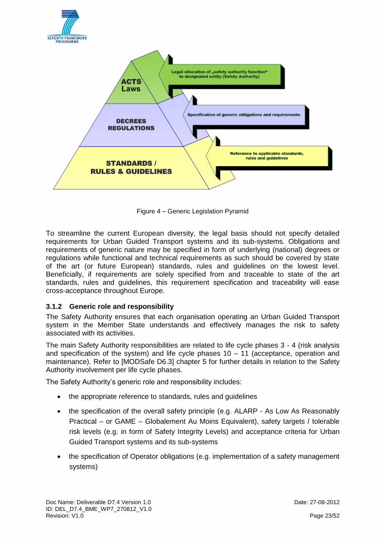
At the discretion of the Operator and / or the Safety Authority, the Independent Safety
Assessor can be involved in all life cycle approach phases. The following figure shows the
typical involvement of the Independent Safety Assessor in relation to the life cycle phases.

Doc Name: Deliverable D7.4 Version 1.0 Date: 27-08-2012 ID: DEL_D7.4_BME_WP7_270812_V1.0 Revision: V1.0 Page 29/52
Refer to [MODSafe D6.3] chapter 5 for further details in relation to the Independent Safety
Assessor involvement per life cycle phases.
System Definition &
Application Conditions
2
Risk Analysis3
Requirements
Specification
4
Apportionment of
System Requirements
5
Design &
Implementation
6
Manufacture7
Installation8
System Validation &
Safety Acceptance
9
System Acceptance10
Performance
Monitoring
12
Modification &
Retrofit
13
Decommissioning
& Disposal
14Operation &
Maintenance
11
Concept1
Independent
Safety
Assessor
Close co-operation
with Safety Authority
Close co-operation
with Supplier
Close co-operation
with Safety Authority
Figure 5 – Independent Safety Assessor involvement
3.3.3 Independent Safety Assessment Methodology
Referring to the Independent Safety Assessor’s role and responsibility as described above –
which means that the extent of involvement of an Independent Safety Assessor may differ
from one given case to another one, the Independent Safety Assessment Methodology
focuses on the judgement on the Supplier’s organisation and processes, in particular on the
Supplier’s verification and validation activities as well as on the functional and technical
safety of the system / function / sub-system / item under assessment.
The Independent Safety Methodology basically distinguishes between the aspects to be
assessed and the techniques that will be applied.
Aspects for Independent Safety Assessment are as follows:
Assessment of Operator’s System Criteria
overall safety target and acceptance criteria
preliminary hazard and risk analysis
overall system safety requirements
Assessment of Supplier’s Quality Management System
quality plan, quality policy, quality procedures
quality management organisation, responsibility, authority & communication
codes and standards applied

Doc Name: Deliverable D7.4 Version 1.0 Date: 27-08-2012 ID: DEL_D7.4_BME_WP7_270812_V1.0 Revision: V1.0 Page 30/52
design and development, configuration management,
requirements implementation and traceability, interface management control
control of production, identification & traceability
monitoring & measuring devices
control of nonconforming product
competence & training
servicing and maintenance requirements
corrective and preventive action
internal and external audits
Assessment of Supplier’s Safety Management System
safety management organisation
verification & validation organisation
independence to safety integrity level
Assessment of Supplier’s Safety Process Implementation
safety plan
safety procedures
safety analysis tools
safety requirements specification process
safety requirements traceability process
test plans and specifications
test equipment and tools
test specifications and reports
verification and validation plan
verification and validation process
verification and validation reports
safety case plan, safety case
the Supplier’s organisation capacity in hazard and risk analyses
identification of hazards and respective risk analysis, hazard log
specification of safety requirements and safety integrity levels
specification of hazards mitigation measures at the design stage and correct implementation
system validation / system tests and hazard closure

Doc Name: Deliverable D7.4 Version 1.0 Date: 27-08-2012 ID: DEL_D7.4_BME_WP7_270812_V1.0 Revision: V1.0 Page 31/52
Assessment of Functional and Technical Safety
preliminary hazard analysis, risk analysis, hazard log
safety architecture, safety integrity allocation
technical documentation, analyses
separation of safety relevant and non-safety relevant functions
system and sub-system analysis and refinement
requirement specifications and traceability
test specifications, test plans and test reports, acceptance criteria
safety case
Assessment of Related Safety Cases
application of cross-acceptance to the extent possible, if applicable
safety related application conditions
The above described independent assessment methodology is by proven project examples
suitable for:
the combination of classical and new technologies
the application for classical systems with driver as well as for modern driverless and
unattended operation
suitable for most complex systems with multiple networked software driven systems
the application of generic product, generic application approvals as base for specific
applications
the application of cross-acceptance to the extent possible

Doc Name: Deliverable D7.4 Version 1.0 Date: 27-08-2012 ID: DEL_D7.4_BME_WP7_270812_V1.0 Revision: V1.0 Page 32/52
3.3.4 Typical Independent Safety Assessor activities in the AAC process
The typical Independent Safety Assessor activities and principle techniques are applied as
appropriate:
liaison with the Safety Authority, the Operator and the Supplier throughout relevant
life cycle phases, ref. [MODSafe D6.3]
preparation of an assessment plan
audits / interviews of Suppliers quality and safety management organisation /
processes
review of documentation such as safety plans, safety concepts, hazard and risk
documentation, requirements -, design- and test specifications, test reports, safety
cases for completeness, validity, unambiguity, comprehensibility and consistency
test witnessing / site inspection throughout different phases, factory and site
inspection, commissioning tests, trial run tests
inspection of safety cases / evidence documentation
usage of cross-acceptance to the extent possible
raise observations and findings
prepare assessment reports and – in certain cases – certifications
interactive, solution-oriented communication
recommendations and lessons learnt to the benefit of the project.
3.4 Supplier(s) generic role and responsibility
3.4.1 Legal Basis
The (legal) basis for the Supplier(s) is formed by the project specific Supplier contract(s). The
Supplier(s) are usually contracted by the Operator.
The Supplier’s liability is limited to his contractual scope and services including product
liability, while safe and orderly operation of the Urban Guided Transport system should be
assigned to be in the responsibility and liability of the Operator.
The Supplier may also be party in a Consortium endorsing the responsibility of operation,
e.g. in case of Public-Private-Partnership (PPP) such as Build-Operate-Transfer (BOT)
contracts.
In these cases the Consortium has to act on the legal basis for Operators and has the
generic role and responsibility of the Operator (see 3.2 of this document).
Doc Name: Deliverable D7.4 Version 1.0 Date: 27-08-2012 ID: DEL_D7.4_BME_WP7_270812_V1.0 Revision: V1.0 Page 33/52
3.4.2 Generic role and responsibility
The Supplier carries the overall responsibility for the evidence of reliability, availability,
maintainability and safety as well as functional performance within his contractual scope.
This includes overall responsibility for his Quality and Safety Management Organisation and
application of appropriate processes and techniques in line with the requirements of the
standards.
The Supplier’s generic role and responsibility is to design, manufacture, install and
commission and test the Urban Guided Transport system and / or its sub-systems, to
perform system validation and to ensure system acceptance and approval.
The main Supplier responsibilities are related to life cycle phases 5 - 6 (design and
implementation of the system). Refer to [MODSafe D6.3] chapter 5 for further details in
relation to the Supplier involvement per life cycle phases.
If a systems, subsystem or component is certified, the Supplier has to ensure the compliance
of each product with the certification on the basis of product liability.
3.4.3 Typical Supplier activities in the AAC process
The typical Supplier activities are:
liaison with the Operator, the Independent Safety Assessor (and the Safety Authority)
throughout relevant life cycle phases, ref. [MODSafe D6.3]
refinement of system requirements to sub-systems / design
design of the system1 / sub-systems / products
manufacture, install, test and commission the system / sub-system / product
the demonstration of fulfilment of safety requirements (ref. EAM in table 2)
the demonstration of fulfilment of functional requirements (ref. EAM in table 2)
the demonstration of fulfilment of system requirements1 / performance of test
operation (ref. EAM in table 2)
determine maintenance regulations in accordance with the operator.
1 In case of turn-key contract.
Doc Name: Deliverable D7.4 Version 1.0 Date: 27-08-2012 ID: DEL_D7.4_BME_WP7_270812_V1.0 Revision: V1.0 Page 34/52
4 Proposal of a core process
The document [URP-FR] sets the following fundamental requirements for urban rail systems regarding procedural requirements. “1.6 Procedural requirements 1.6.1. The conditions for safe and orderly operations and maintenance shall be defined in a way allocating the responsibilities clearly. They shall ensure that infrastructure, rolling stock and other subsystems are in a safe condition and that operations are conducted in a safe way and do not constitute a danger to health nor harm the environment. 1.6.2. In case operations are shared between different entities (e.g. rolling stock is operated by a different Transport Company than operations facilities) these entities shall come to an agreement on the split of responsibility for the entire operations process. 1.6.3. Any construction or modification to infrastructure, rolling stock or other subsystems which might interfere with operations shall be subject to the agreement of the entity responsible for operations. 1.6.4. Setting infrastructure, rolling stock and other subsystems into operation for passenger service shall be subject to a process for approval and/or acceptance allocating the responsibility clearly between the involved entities. In order to ensure safe and orderly operations, adequate documentation shall be provided by all parties involved.” A core process for acceptance, approval and certification may be composed of practices of different cities and/or countries. Table 8 of [MODSafe D7.3] (shown as Table 1 in this deliverable) shows such common practices. After the evaluation of this table, the following consequences can be drawn:
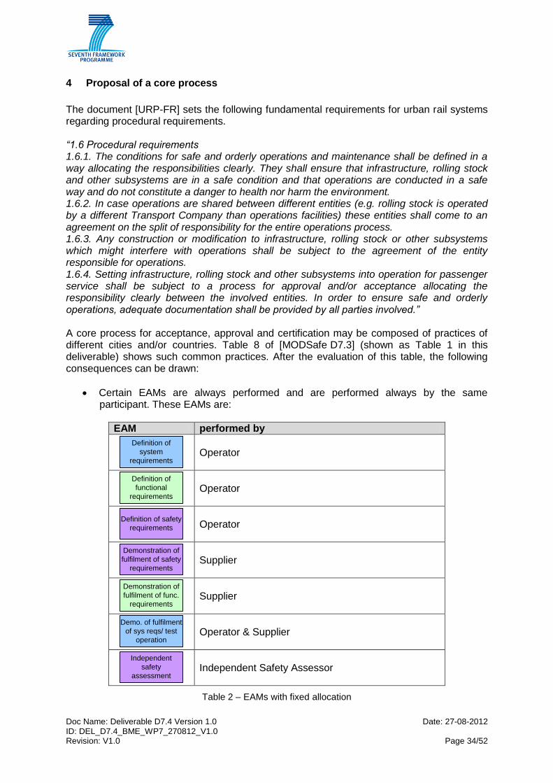
Certain EAMs are always performed and are performed always by the same participant. These EAMs are:
EAM performed by
Definition of
system
requirements
Operator
Definition of
functional
requirements
Operator
Definition of safety
requirements
Operator
Demonstration of
fulfilment of safety
requirements
Supplier
Demonstration of
fulfilment of func.
requirements
Supplier
Demo. of fulfilment
of sys reqs/ test
operation
Operator & Supplier
Independent
safety
assessment
Independent Safety Assessor
Table 2 – EAMs with fixed allocation

Doc Name: Deliverable D7.4 Version 1.0 Date: 27-08-2012 ID: DEL_D7.4_BME_WP7_270812_V1.0 Revision: V1.0 Page 35/52
Certain EAMs are always performed, but they are performed by different participants/organisations according to the different practices of different countries. These EAMs are:
EAM can be performed by
Check of safety
requirements
Operator, Supplier, Safety Authority or Independent Safety Assessor (or Certification Body)
Check of fulfilment
of safety
requirements
Operator, Supplier, Safety Authority or Independent Safety Assessor (or Certification Body)
Check of fulfilment
of system
requirements
Operator, Supplier, Safety Authority or Independent Safety Assessor (or Certification Body)
Approval
Operator or Safety Authority
Table 3 – EAMs with variable allocation
Certain EAMs are not performed in every case or not performed as formal responsibility. These EAMs are:
EAM
Check of system
requirements
Check of
functional
requirements
Check of fulfilment
of functional
requirements
Table 4 – Optional EAMs
Therefore three groups of EAMs can be identified:
EAMs with fixed allocation,
EAMs with variable allocation,
optional EAMs. The core process is therefore based on EAMs, which are always performed. The variable allocation EAMs and the optional EAMs provide a “playground” for a case to case adaptation of AAC processes. Such a core process is demonstrated in Table 5.
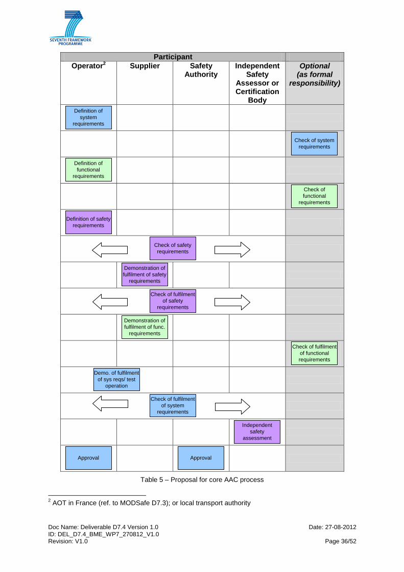
Doc Name: Deliverable D7.4 Version 1.0 Date: 27-08-2012 ID: DEL_D7.4_BME_WP7_270812_V1.0 Revision: V1.0 Page 36/52
Participant
Operator2 Supplier Safety Authority
Independent Safety
Assessor or Certification
Body
Optional (as formal
responsibility)
Definition of
system
requirements
Check of system
requirements
Definition of
functional
requirements
Check of
functional
requirements
Definition of safety
requirements
Check of safety
requirements
Demonstration of
fulfilment of safety
requirements
Check of fulfilment
of safety
requirements
Demonstration of
fulfilment of func.
requirements
Check of fulfilment
of functional
requirements
Demo. of fulfilment
of sys reqs/ test
operation
Check of fulfilment
of system
requirements
Independent
safety
assessment
Approval
Approval
Table 5 – Proposal for core AAC process
2 AOT in France (ref. to MODSafe D7.3); or local transport authority

Doc Name: Deliverable D7.4 Version 1.0 Date: 27-08-2012 ID: DEL_D7.4_BME_WP7_270812_V1.0 Revision: V1.0 Page 37/52
In general terms, the aim of creating formal procedures is to make the processes clearer and to keep the process under control. Both aspects are needed to have more reliable processes in order to improve the confidence that the product will meet its requirements and is appropriate for use. The confidence that a product is appropriate for use can be improved by two means from the process point of view:
- introduce additional phases (tasks, formal steps) in a process, - allocation of the phases to different, independent participants, to increase
independency (of course, there is a logical and obvious allocation of certain tasks to certain participants from their nature).
These two options can be adjusted for AAC processes by applying or not applying optional EAMs, furthermore by allocating EAMs to different partners for variable allocation EAMs.
Doc Name: Deliverable D7.4 Version 1.0 Date: 27-08-2012 ID: DEL_D7.4_BME_WP7_270812_V1.0 Revision: V1.0 Page 38/52
5 Adapting the core AAC process
The organisation of AAC processes may be influenced by several factors. These factors include:
size of a system,
the complexity of the system,
level of safety (SIL),
nature of the project,
grade of automation,
the type of system (tram/metro/light rail). In the subsequent clauses these factors are introduced and their possible effect on the core AAC process is investigated.
5.1 Size of the system
Size of a UGT system can be interpreted according to several aspects. These aspects include:
length of lines,
number of lines,
design of civil works,
distance between stops,
interconnections in the network.
Size of the system Effect on AAC process
The size of a UGT system, in general, does not affect the process of acceptance, approval and certification, if the size is interpreted as the extent, length of line, number of stations etc. Certainly, the amount of necessary activities differs from case to case, but the nature of the process and the allocation of EAMs will not be changed for different size of UGT systems.
5.2 Complexity of the system
In general context a complex system is a system perceived as complex because its definition and its behaviour cannot be deduced from the knowledge of its components. Complexity does not result from the number of components or number of types of components in the system, or even from their interrelations. As long as components can be counted, the system is at most only complicated (or even hyper-complicated). Complexity is characterised by the potential unpredictability of the behaviour of the system (behaviour that cannot be computed a priori), coming from in particular the recursive nature of the functioning of its components (components change their behaviour as they operate).

Doc Name: Deliverable D7.4 Version 1.0 Date: 27-08-2012 ID: DEL_D7.4_BME_WP7_270812_V1.0 Revision: V1.0 Page 39/52
The complexity of UGT systems is mainly determined by operational and technological aspects influencing the extent of the needed procedures. In this sense complexity is driven by the following factors:
Existing technology, uniform or mixed technologies (electronics [incl. software], electrical or mechanical systems and multiple interfaces).
Integrating new subsystem(s) in existing system, multiple interfaces
New technology already partly or totally certified
New technology experienced in other industries
New technology not experienced Beyond operational and technological aspects, complexity is further driven by infrastructure and performance aspects.
The simplest case is probably the UGT system with civil works limited to building tracks at street level. Complexity therefore is influenced by the following factors:
grade separation by building the system in tunnels or on elevated structure (stations, stops and terminals). Civil constructions may include bridges and tunnels and underground / above ground stations, requiring the consideration of and interaction with the civil works authority and their requirements, other public authorities and stakeholders such as police, fire brigade, rescue.
the capacity of the system and overall layout o track length, o number of stations, o location of traction power sub-stations, o location, size and organisation of workshops etc.
the performances required from the system o headway, o traffic flows separation, o access control etc.
The basic operational requirements are generally defined in feasibility studies and preliminary design studies developed by specialised transport planners, design consultants and engineering companies.

Doc Name: Deliverable D7.4 Version 1.0 Date: 27-08-2012 ID: DEL_D7.4_BME_WP7_270812_V1.0 Revision: V1.0 Page 40/52
Complexity of the system Effect on AAC process
The complexity of a UGT system depends on several factors, therefore one single measure or scale for complexity cannot be defined. An important character of complex system is that their behaviour cannot be (easily) estimated. In order to have more confidence in the system and to ensure that it corresponds with its requirements, faults must be avoided during the development and removed before putting the UGT system into service. These techniques are generally supported by strictly controlled development processes. With respect to acceptance, approval and certification, the confidence in the process can be improved by
performing more optional EAMs and by
performing variable allocation EAMs by independent partners (see chapter 4 for optional and variable allocation EAMs).
Confidence in the AAC process will increase as more optional EAMs are performed and greater degrees of independence between entities is introduced.
Doc Name: Deliverable D7.4 Version 1.0 Date: 27-08-2012 ID: DEL_D7.4_BME_WP7_270812_V1.0 Revision: V1.0 Page 41/52
5.3 Level of safety
According to CENELEC EN 50126 standard, safety integrity is defined as the “ability of a safety-related system to satisfactorily perform the required safety-related function under all the stated conditions within a stated operational environment and a stated period of time”. The term safety integrity level (SIL) is defined in the same standard as “one of a number of defined discrete levels for specifying the safety integrity requirements of the safety functions to be allocated to the safety related systems”. For an analysis of safety requirements for MODSafe continuous safety measures and functions, see [MODSafe D4.2]. The spectrum of requirements varies as follows:
1. SIL 0 functions / sub-systems, which require limited Supplier evidence and limited
Independent Safety Assessor involvement. SIL 0 is usually assigned to non-safety
functions. However these functions still require high quality and availability such as
train supervision, control centre functions, etc. [MODSafe D4.2] and [MODSafe D4.3]
provide a sound overview of standard assignments.
Note, that according to [prEN50126] SIL 0 is defined in two ways. Quantitatively: the
TFFR is less demanding than 10-5 per hour; or qualitatively: SIL0 can be allocated to
functions that could be safety related but whose safety impact remains low.
2. SIL 1 / SIL 2 functions / sub-systems, which require Supplier evidence and
Independent Safety Assessor involvement and has requirements regarding the
independence of the Supplier’s Verification and Validation organisation and the
Independent Safety Assessor. Depending on the operational context, SIL 1/2
functions may be assigned to fire detection functions, communication functions, door
functions and various further individual functions / sub-functions, e.g. on Rolling
Stock. [MODSafe D4.2] and [MODSafe D4.3] provide a sound overview of standard
assignments.
3. SIL 3 / SIL 4 functions / sub-systems, which require exhaustive Supplier evidence and
strong Independent Safety Assessor involvement with strong requirements regarding
the independence of the Supplier’s Verification and Validation organisation and the
Independent Safety Assessor. SIL 4 functions are usually assigned to system safety
functions, the sub-system signalling functions and various other individual functions.
[MODSafe D4.2] and [MODSafe D4.3] provide a sound overview of standard
assignments.
As also described in [MODSafe D6.3], the decision on the involvement of an Independent
Safety Assessor is at the discretion of the Safety Authority.
According to [CENELEC] standards, depending on the safety integrity level, a necessary
independence between the roles of a development process shall be created (see Figure 6;
note, that Figure 6 is composed on the basis of [prEN50126], part 4).
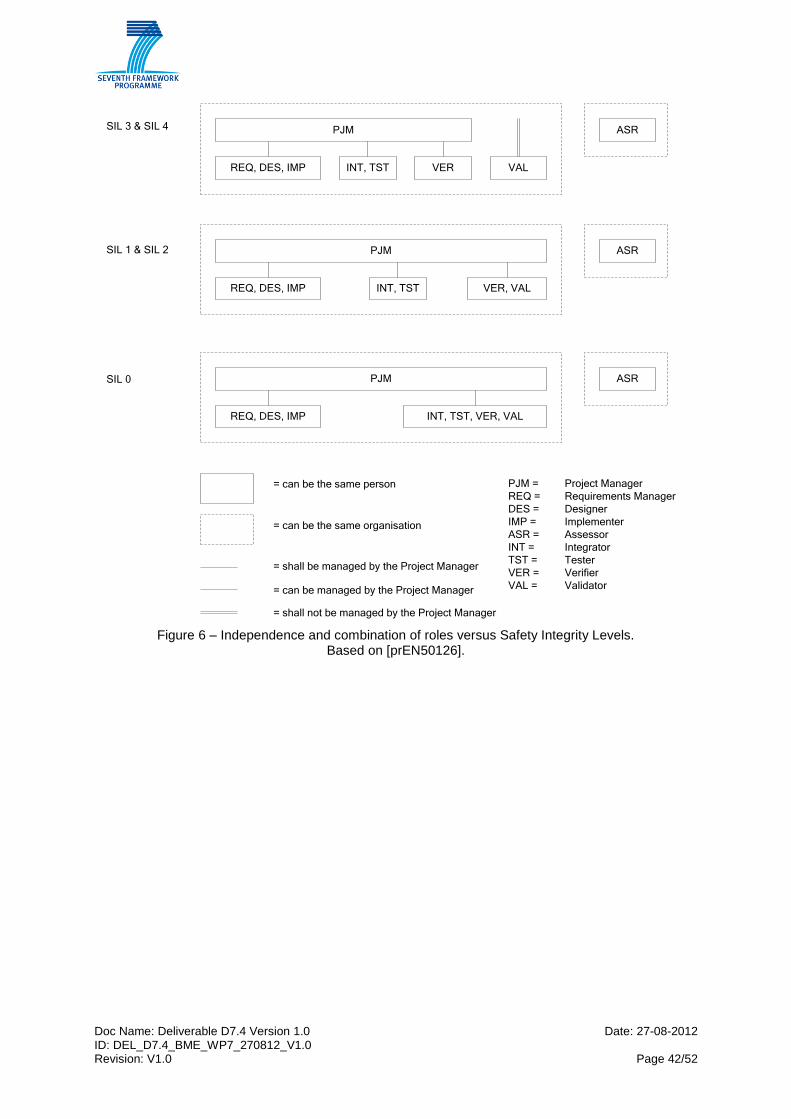
Doc Name: Deliverable D7.4 Version 1.0 Date: 27-08-2012 ID: DEL_D7.4_BME_WP7_270812_V1.0 Revision: V1.0 Page 42/52
PJMSIL 3 & SIL 4
SIL 1 & SIL 2
SIL 0
REQ, DES, IMP INT, TST VER VAL
ASR
PJM
REQ, DES, IMP INT, TST VER, VAL
ASR
PJM
REQ, DES, IMP INT, TST, VER, VAL
ASR
= can be the same person
= can be the same organisation
= shall be managed by the Project Manager
= can be managed by the Project Manager
= shall not be managed by the Project Manager
PJM = Project Manager
REQ = Requirements Manager
DES = Designer
IMP = Implementer
ASR = Assessor
INT = Integrator
TST = Tester
VER = Verifier
VAL = Validator
Figure 6 – Independence and combination of roles versus Safety Integrity Levels.
Based on [prEN50126].

Doc Name: Deliverable D7.4 Version 1.0 Date: 27-08-2012 ID: DEL_D7.4_BME_WP7_270812_V1.0 Revision: V1.0 Page 43/52
Level of Safety Effect on AAC process
The effect of safety integrity on the AAC process can be investigated from two aspects.
1.) Optional EAMs The [CENELEC] standards propose to apply a life cycle process. A MODSafe life cycle process is proposed in [MODSafe D6.3] too. Important activities in this life cycle are the verification and validation. The optional EAMs (as described in chapter 4): “Check of system requirements”, “Check of functional requirements” and “Check of fulfilment of functional requirements” can be interpreted as verification and validation activities (even if verification and validation is required strictly only for safety functions, according to [CENELEC]). Therefore if a UGT system has to fulfil SIL requirements (i.e. it performs any safety function), it is advisable to perform these optional EAMs.
2.) Independence
As described in this sub-clause, the [CENELEC] standards require defined levels of independence between entities of the process (see Figure 6). If a UGT system has to fulfil SIL requirements, it is advisable to arrange the level of independence of verification and validation activities in such a way that it will correspond to the appropriate requirements of [CENELEC]. Verification and validation are internal activities performed by the Supplier, so the allocation of the variable allocation EAMs shall be done at a more detailed level, within the organisation of the Supplier. In any case, and according to the [CENELEC] standards, the Independent Safety Assessor must always stay independent from the Supplier.

Doc Name: Deliverable D7.4 Version 1.0 Date: 27-08-2012 ID: DEL_D7.4_BME_WP7_270812_V1.0 Revision: V1.0 Page 44/52
5.4 Nature of the project
Under the nature of the project a differentiation can be made if it is a new system to build, or an extension, variation or modification of an existing system is carried out. The range can vary according to the following aspects:
Building a totally new system
A system, built totally new or an additional line of an existing network with different technology, which is not compatible with the existing one.
Renewal or exchange of subsystems or components of an existing system
These are measures where the complexity varies widely. The “like-for-like” exchange of components or even subsystems can be done quite easily as a part of maintenance (using spare parts). Whenever the new parts or new integrated subsystems have a changed design or even technology (compared with the exchanged component or subsystem), often a complete AAC- process is needed especially because of problems at interfaces or component/sub-system performance differences between the old and the new component/sub-system.
Extension of an existing system/using existing technology already used in the
system or new technology
Mainly the extension of an existing system using existing technology is less complicated than an extension using other technologies.
Upgrade of an existing system
Upgrade of an existing system with changes on the existing technical equipment
and/or adding components with new technology. Upgrade can be done at system,
subsystem or component level.
In that point of view some countries (e.g. France, UK) introduce a notion of “substantiality” of changes in their regulation, the AAC process for proposed changes being directly dependent upon this substantiality level. Following clause 3 of the French Decree 2003-425 relating to safety of public guided transports, a “modification to a public guided transport system is substantial as soon as it modifies the safety demonstration presented in the [legal] safety files […] or as soon as it leads to a noticeable change of system’s safety functions or requires the use of new technologies”. The decree adds the precision that “putting into service on an existing infrastructure, a vehicle or an equipment identical to a similar element already put into service” can be considered as substantial as soon as one of the two preceding criteria are met. The open question now being how to determine (and who determines) if a change induces a modification in safety demonstrations or a noticeable change in safety functions. Practically (but this process is not described in decrees), the Supplier performs an analysis describing the proposed change and its possible safety impacts. Then the Operator produces a succinct document based on the analysis proposing to consider (or not) the change as substantial and submits it to the Safety authorities who can require an evaluation by an Independent Safety Assessor (concerning the substantiality level of the change).
Doc Name: Deliverable D7.4 Version 1.0 Date: 27-08-2012 ID: DEL_D7.4_BME_WP7_270812_V1.0 Revision: V1.0 Page 45/52
A very similar practice is used in the UK. The [ORR Guide SV] describes that a safety verification must take place if new or altered vehicles or infrastructure are about to be introduced into service, the design, construction, or testing of which:
incorporates significant changes compared to any vehicle or infrastructure already in use on the transport system; and
would be capable of significantly increasing an existing risk or creating a significant new safety risk.
The document [ORR Guide SV] gives some guidance, in which cases a project might lead to the application of safety verification:
novel technology is being introduced or the use of technology that is entirely new to the transport system;
existing technology is being used in novel ways or situations;
existing technology is being required to deliver very significant increases in performance or output.
Examples of specific situations that might be considered novel are:
the introduction of existing vehicles new to a route;
the introduction of selective door opening using Global Positioning Systems;
the use of automated/driverless vehicles (see also sub-clause 5.5).
Nature of the project Effect on AAC process
The management of changes on UGT systems and particularly their impact on the AAC process is a very important issue. Clearly the type of these changes (in terms of impact on the safety demonstration of the systems) influence the existence (or not) of a specific AAC process relative to changes on systems already put into service. The substantiality (or not) of a change directly has an impact on the AAC process, in that sense that a substantial modification is considered like a new project (with exactly the same process, the same milestones, the same documents to provide), whereas for a non substantial modification there is no AAC process at all (but a simple information is provided to the safety authority).
Doc Name: Deliverable D7.4 Version 1.0 Date: 27-08-2012 ID: DEL_D7.4_BME_WP7_270812_V1.0 Revision: V1.0 Page 46/52
5.5 Grade of Automation
An important issue in UGT-systems is the grade of automation (GOA) of the operation. The spectrum varies from having
1. Tram systems with driver and driving on sight
2. Light rail or metro systems with driver and semi-automatic / automatic train
control / protection
3. Metro systems being driverless or unattended with more complex functionality
on the signalling and Rolling Stock and Central Control side as well as
potentially requiring further sub-systems and aspects such as platform screen
doors, access control, intrusion detection, CCTV, etc.
Note that generally the lower the grade of automation is, the more staff is involved in
ensuring safety of the system. The operator has to ensure the safety by editing operation-,
service- and maintenance- regulations and by training of staff on the basis of these
regulations.
Grade of Automation Effect on AAC process
It is evident that different GOAs have major effect on hazard and risk analysis, and therefore on the system, functional and safety requirements, technical solution as well as on operational requirements. It is important to examine whether the GOA has any impact on AAC processes. From the practices of different countries (especially which are operating higher level GOA systems too) the results are clear: it was found that the AAC process does not vary with respect to different GOAs. But the GOA may be the reason for the complexity of the system or a higher GOA may be the result of the upgrade of a system (see sub-clauses 5.2 and 5.4). In other words: the technical and operational features of a system may be different depending on the GOA, but the process, how these system are approved, accepted and certified remains the same.
5.6 Type of system (tram/ light rail / metro)
Urban Guided Transport systems (UGT), which cover Metro, Tram and Light Rail, are defined as public transport systems permanently guided at least by one rail, intended for the operation of local, urban and suburban passenger services with self-propelled vehicles and operated either segregated or not segregated from general road and pedestrian traffic. (The segregation is achieved by appropriate measures such as kerbstones, railings, hedges, rows of trees, level crossings or fixed barriers e.g. fences.) A light rail system using the tracks of heavy rail lines to include suburbs and regional environs in their service is no longer an Urban Guided Transport system as soon as European rail transport regulations will apply to these shared track sections. In such a case it is a mix of two categories of infrastructure on which are running hybrid vehicles. Such a

Doc Name: Deliverable D7.4 Version 1.0 Date: 27-08-2012 ID: DEL_D7.4_BME_WP7_270812_V1.0 Revision: V1.0 Page 47/52
system is usually referred to as “tram-train”. Similar hybrids may be found for some metro-train systems. Such systems are out of scope of MODSAFE. Trams and light rail systems are run ‘on sight’ (except for some light rail systems operated as pre-metro). This signifies that the driver of such a rail-bound vehicle bears the same kind of responsibility as the driver of a car or lorry. Planning the route of trams or light-rail systems, including stops, pedestrian crossings or joint crossings with road traffic, needs to be aligned with the competent local road transport authorities. Alongside this formal coordination with existing traffic regulations, proposals for tram or light rail systems also need to be made in agreement with urban development plans. This coordination, as well as the related permits, must be ensured well before commencing the technical approval procedure. Risk assessment is not necessary under road traffic regulations. It is not possible to automate road and light rail systems on shared road space. Planning the route of metro lines, as well as the location of metro stations and access staircases, also needs to be coordinated with urban authorities, but on different basis, e.g. in terms of coordination between modes (park-and-ride) or with urban planners and developers. Metro service can be provided by trains with drivers and appropriate train control and signalling systems or by trains run in automatic (driverless or unattended) mode.
Type of system Effect on AAC process
The effect of the type of the UGT system on the AAC process organisation is indirect. Tramway systems require lower safety requirements, as they are running on sight, while metro and light rail system are designed generally to cope with higher safety integrity requirements. Refer to sub-clause 5.3 regarding the effect of safety level on AAC processes. Tramway systems are often treated as a part the road traffic system, therefore the involvement of other authorities (e.g. authority responsible for road traffic) is often necessary. This must be considered in case of tramway systems.

Doc Name: Deliverable D7.4 Version 1.0 Date: 27-08-2012 ID: DEL_D7.4_BME_WP7_270812_V1.0 Revision: V1.0 Page 48/52
6 Cross acceptance
At a high level, the concept of cross acceptance puts forward the scenario ‘that if a
technology/system operated safely and reliably in one country, then it should be able to do
so in another country without the need for back to basics approval tests” [IRSE-Rep.6].
Cross acceptance is defined in EN 50129 as “The status achieved by a product that has
been accepted by one Authority to the relevant European Standards and is acceptable to
other Authorities without the necessity for further assessment”.
Cross-acceptance is also handled in [MODSafe D6.2], sub-clause 5.3.2 (Cross-acceptance
of products and sub-systems), as well as in [MODSafe D6.3], sub-clause 5.10.4 (Application
of Cross-Acceptance). In WP6 cross-acceptance is examined from the viewpoint of life cycle.
Main techniques and practices with examples are described in detail in [MODSafe D6.3].
[TR 50506-1], an application guide for EN 50129 provides different criteria and aspects to be
considered for cross acceptance. [TR 50506-1] identifies the following criteria:
the product subject to the assessment is well defined (description, documents,
software configuration, …);
the standards or other normative documents used to establish the results of safety
assessment are well defined and appropriate;
the methodology used by safety assessors is well defined and appropriate;
the limits of validity of the safety assessment result are well defined;
the standards, methods, conditions, limitations and restrictions are also applicable for
the particular situation for which cross-acceptance is desired.
The use of elementary activity modules (EAMs) as defined in [MODSafe D7.2] in cross-
acceptance processes offers some benefits as well. Some of the criteria, which must be
investigated for a cross-acceptance, can be checked more easily if the acceptance, approval
and certification processes of the different applications are described with help of EAMs.
EAMs may provide a “common language” for the common understanding of existing
assessments and approvals.
6.1 Criteria for Cross-Acceptance
The main acceptance criteria for cross-acceptance are related to
features and application conditions of the system to be cross-accepted
Independent Safety Assessor independence
Independent Safety Assessor qualification
Content and depth (see Figure 7) of the Approval Certificate to be cross-accepted
Doc Name: Deliverable D7.4 Version 1.0 Date: 27-08-2012 ID: DEL_D7.4_BME_WP7_270812_V1.0 Revision: V1.0 Page 49/52
Documentation that has been assessed to deliver the Certificate of the system to be cross-accepted (including the Safety Case)
Concerning the features and application conditions of the system to be cross-accepted, the hypotheses relative to a new environment should be made explicit, in the form of, for example, requirements exported to the new environment, operation and maintenance (any external factors that could invalidate the hypotheses made for the initial certified system should be taken into account). The following aspects should be considered:
1. The environment of use A new environment could call into question the safety objective targeted by the initial certificate. Therefore, the environment of use of the initial certified system should be considered, namely the physical and/or operational interfaces with other systems and/or organisations. A systems approach should be led to identify all the constraints due to the environment of use of the system. These constraints are either exported from the system to be cross-accepted to the future environment of use, or imported from the environment of use to the system to be cross-accepted.
2. The physical constraints Are the physical constraints identical? If not, does it have an impact on safety? Among the physical constraints we can cite: the climatic conditions (temperature, hygrometry, etc.), the mechanical constraints (vibrations, etc.), the electrical constraints (characteristics of the power supply, the insulations...), conditions related to the electromagnetic environment, conditions related to a more or less polluted environment (dust, vapour, corrosive gas, etc.)...
3. The cultural background How systems are operated (configuration of the programmable system, security alarms, protections against unauthorised access...) and how they are maintained (installation, test and storage rules, use of specific testing and measuring devices...), how well procedures are being applied, the level of training of the users and maintenance operators, etc. can change the requirements applicable to the system.
4. The operating rulebook It is rarely the case that a totally new operating rulebook is implemented at the same time than a new system. Rules applicable to the system which has been certified are based on explicit or implied hypotheses that should be taken into account. These rules should be made explicit, along with any need to amend them, and can be formulated as safety requirements exported to the operating procedures.
6.2 Depth of a safety assessment
The following figure illustrates the different depths of assessment that a product can be subjected to. It is crucial to understand what exactly has been initially assessed when you want to apply cross-acceptance, to ensure that the final safety demonstration is complete and covers the specific product application that is to be put into operation. A detailed analysis of the initial safety demonstration and of the assessment performed is necessary to measure what depth of assessment has been achieved.

Doc Name: Deliverable D7.4 Version 1.0 Date: 27-08-2012 ID: DEL_D7.4_BME_WP7_270812_V1.0 Revision: V1.0 Page 50/52
Ins
pe
cti
on
Bo
die
s
Ce
rtif
ica
tio
n B
od
ies
EN
50
12
6, E
N5
01
28
an
d E
N5
01
29
sta
nd
ard
s1
Ge
ne
ric
ru
les, la
ws
an
d d
ec
ree
s
or
pro
jec
t s
pe
cif
ic s
afe
ty
req
uir
em
en
ts (
i.e
. c
lie
nt
sp
ec
ific
ati
on
s)
WH
AT
SH
OU
LD
BE
AC
HIE
VE
DW
HA
T S
HO
UL
D B
E U
ND
ER
TA
KE
N
Qu
alit
y
insu
ran
ce
re
qu
ire
me
nts
(e.g
. IS
O 9
00
1)
Fo
rma
lisa
tio
n
an
d d
ocu
me
nt
tra
ce
ab
ility
re
qu
ire
me
nts
Me
tho
do
log
ica
l re
qu
ire
me
nts
on
sa
fety
a
sse
ssm
en
t
Org
an
isa
tio
n,
ind
ep
en
de
nce
a
nd
skill
re
qu
ire
me
nts
Me
tho
do
log
ica
l re
qu
ire
me
nt o
n
ve
rifica
tio
n/
va
lida
tio
n a
nd
te
sts
Re
qu
ire
me
nts
on
h
ow
qu
an
tita
tive
sa
fety
ob
jective
s
are
de
fin
ed
, a
pp
ort
ion
ed
an
d
ach
ieve
d
Ag
ain
st syste
ma
tic
failu
res
Ag
ain
st ra
nd
om
fa
ilure
s
Co
ve
rag
e o
f e
ach
accid
en
tal
sce
na
rio
at
eve
ry le
ve
l2
Ach
ievin
g o
f ta
rge
ted
q
ua
ntita
tive
sa
fety
ob
jective
s
Ag
ain
st ra
nd
om
fa
ilure
sA
ga
inst syste
ma
tic
failu
res
1 s
afe
ty a
sse
ssm
en
t is
no
t n
ece
ssa
rily
lim
ite
d
to E
N5
01
26/8
/9 s
tan
da
rds, it u
su
ally
co
ve
rs
the
wh
ole
sp
ectr
um
of sa
fety
re
qu
ire
me
nts
(a
lso
de
rive
d fro
m o
the
r sta
nd
ard
s a
nd
re
gu
latio
ns)
ba
se
d o
n th
e k
ey s
tan
da
rds
EN
50
12
6/8
/9.
2 s
yste
m, su
b-s
yste
m, e
qu
ipm
en
t, h
ard
wa
re,
so
ftw
are
Sa
fety
pro
ce
ss a
sse
ssm
en
t
Pro
du
ct S
IL a
sse
ssm
en
t
Sa
fety
asse
ssm
en
t o
f th
e p
rod
uct
Te
ch
nic
al
req
uire
me
nts
on
d
esig
n a
nd
a
rch
ite
ctu
re
Asse
ssm
en
t o
f th
e c
om
plia
nce
with
th
e E
N5
01
2X
sta
nd
ard
s
Te
ch
nic
al
req
uire
me
nts
on
d
eve
lop
me
nt
Th
e p
roce
ss u
nd
ert
ake
n
giv
es c
on
fid
en
ce
in
th
e
ach
ievm
en
t o
f th
e s
afe
ty
req
uire
me
nts
Th
e r
eq
uire
me
nts
of th
e
EN
50
12
X s
tan
da
rds a
re
me
t
Th
e p
rod
uct is
co
mp
lian
t w
ith
th
e S
ILX
re
qu
ire
me
nts
No
da
ng
ero
us b
eh
avio
ur
ha
s b
ee
n d
ete
cte
d
Co
nclu
sio
n :
Co
nclu
sio
n :
Co
nclu
sio
n :
Co
nclu
sio
n :
- N
o «
ho
les »
in
th
e s
pe
cific
atio
ns
- N
o d
an
ge
rou
s b
eh
avio
urs
of th
e
syste
m
- A
pp
rop
ria
te s
afe
ty c
lassific
atio
n
- C
orr
ect d
ata
/pa
ram
ete
rs
- A
pp
rop
ria
te r
esp
on
se
tim
e
pe
rfo
rma
nce
s
- C
orr
ect in
sta
llatio
n o
n s
ite
- E
tc.
- A
pp
rop
ria
te a
rch
ite
ctu
re
- S
uffic
ien
t re
liab
alit
y/
ma
inte
na
nce
- E
tc.
Le
ve
l o
f co
nfid
en
ce
giv
en
to
a s
yste
m a
bo
ut th
e fa
ct th
at it m
ee
ts its
sa
fety
re
qu
ire
me
nts
Sa
fety
re
qu
ire
me
nts
Ind
ep
en
de
nt
Sa
fety
As
se
ss
ors
(IS
A)
Figure 7 – Depth of the safety assessment
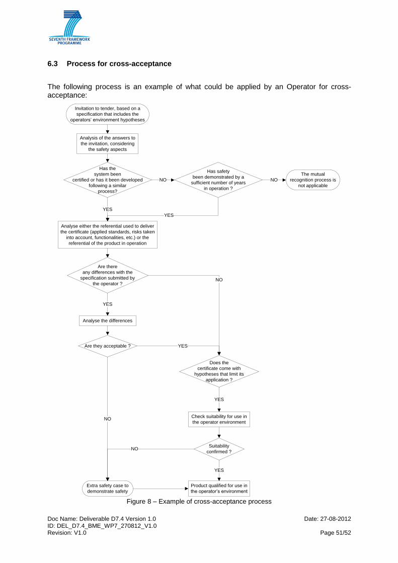
Doc Name: Deliverable D7.4 Version 1.0 Date: 27-08-2012 ID: DEL_D7.4_BME_WP7_270812_V1.0 Revision: V1.0 Page 51/52
6.3 Process for cross-acceptance
The following process is an example of what could be applied by an Operator for cross-acceptance:
Invitation to tender, based on a
specification that includes the
operators’ environment hypotheses
Analysis of the answers to
the invitation, considering
the safety aspects
Has the
system been
certified or has it been developed
following a similar
process?
Does the
certificate come with
hypotheses that limit its
application ?
Has safety
been demonstrated by a
sufficient number of years
in operation ?
NO
The mutual
recognition process is
not applicable
NO
Check suitability for use in
the operator environment
Suitability
confirmed ?
Analyse either the referential used to deliver
the certificate (applied standards, risks taken
into account, functionalities, etc.) or the
referential of the product in operation
Are there
any differences with the
specification submitted by
the operator ?
YES
YES
Analyse the differences
Are they acceptable ?
Extra safety case to
demonstrate safety
NO
NO
YES
YES
NO
YES
Product qualified for use in
the operator’s environment
YES
Figure 8 – Example of cross-acceptance process
Doc Name: Deliverable D7.4 Version 1.0 Date: 27-08-2012 ID: DEL_D7.4_BME_WP7_270812_V1.0 Revision: V1.0 Page 52/52
7 Conclusion
In this deliverable a generic framework for the acceptance, approval and certification processes of UGT systems has been proposed. In chapter 3 a proposal was given for generic roles and responsibilities of the participants of the acceptance, approval and certification processes. The framework is composed of a core process (see chapter 4). This core process can be adjusted or adapted to specific needs. Guidance for case to case adaptation was described in chapter 5. The description of the generic framework for AAC processes has been completed by a guidance to cross acceptance in the field of UGT systems. To summarise the benefits of the work package 7 two main points can be identified:
On one hand, the introduction of Elementary Activity Modules provides a common
language for all participants of acceptance, approval and certification processes. The
use of EAMs as a common language can help understanding differences in different
processes, different processes can be compared and thus the cross acceptance can
be eased in the field of urban guided transit systems.
On the other hand, a very important achievement of work package 7 is the proposal
of a generic process for acceptance, approval and certification. The generic process
is intended for voluntary use. The generic process is composed of a core process and
of a guide for adapting the core process for specific needs. This method allows the
appliers to create less complex processes for less critical projects, and by that it can
help to improve the competitiveness of urban guided transit systems.