EUROPEAN COMMISSION DG RTD - TNOpublications.tno.nl/publication/100344/keDDiH/Assess-D4-1.pdf ·...
45
EUROPEAN COMMISSION DG RTD SEVENTH FRAMEWORK PROGRAMME THEME 7 TRANSPORT - SST SST.2008.4.1.1: Safety and security by design GA No. 233942 ASSESS Assessment of Integrated Vehicle Safety Systems for improved vehicle safety Deliverable No. ASSESS D4.1 Deliverable Title Action plan pre-crash evaluation Dissemination level Public/ Confidential/Restricted Written By Oliver Bartels / Tobias Langner (BASt), Andrés Aparicio (IDIADA), Paul Lemmen (FTSS), Carmen Rodarius (TNO) 22/02/2010 Checked by Ton Versmissen (TNO) 24/02/2010 Approved by Paul Lemmen (FTSS) 28/02/2010 Issue date February 2010
Transcript of EUROPEAN COMMISSION DG RTD - TNOpublications.tno.nl/publication/100344/keDDiH/Assess-D4-1.pdf ·...

EUROPEAN COMMISSION
DG RTD SEVENTH FRAMEWORK PROGRAMME
THEME 7 TRANSPORT - SST
SST.2008.4.1.1: Safety and security by design GA No. 233942
ASSESS Assessment of Integrated Vehicle Safety Systems for improved
vehicle safety
Deliverable No. ASSESS D4.1
Deliverable Title Action plan pre-crash evaluation
Dissemination level Public/Confidential/Restricted
Written By Oliver Bartels / Tobias Langner (BASt), Andrés Aparicio (IDIADA), Paul Lemmen (FTSS), Carmen Rodarius (TNO)
22/02/2010
Checked by Ton Versmissen (TNO) 24/02/2010
Approved by Paul Lemmen (FTSS) 28/02/2010
Issue date February 2010

ASSESS D4.1 – Action Plan for Standardization of Track and Lab tests Public
2/45
Executive summary
This deliverable “Action plan pre-crash evaluation” forms the starting point of WP4 pre-crash evaluation. This document mainly is the outcome of a two days workshop held at BASt. It is strongly linked to the WP1.1 results that came up with data concerning the accident situation on European roads. WP1.1 provides in its deliverable D1.1 a list of accident situations, ranked by frequency and further more ranked by injury costs (injury costs = frequency x casualty costs weighting factors). The ranking of the preliminary accident scenarios from the analysis in WP1 is:
Rank Accident type 1 Type 1a: Driving accident - single vehicle 2 Type 6: Accidents in longitudinal traffic (6a and 6b included) 3 Type 2&3: Accidents with turning vehicle(s) or crossing paths in junction 4 Type 6b: Accidents in longitudinal traffic - opposite direction 5 Type 6a: Accidents in longitudinal traffic - same direction 6 Type 4: Accidents involving pedestrians
WP1 results consider all type of accidents happening on the road with at least one vehicle involved. However, for the WP4 activities no single vehicle driving accidents (type 1a) will be considered as they describe mainly loss of control situations which are out of the scope of the systems under investigation in this project. Also accidents involving vulnerable road users, such as pedestrians (type 4) and cyclists, are outside the objectives of the ASSESS project. The analysis has confirmed that the systems selected within the ASSESS project are relevant with respect to the current casualty problems, with Type 6 and Type 2 & 3 accidents being most relevant for the pre-crash systems under investigation within ASSESS. Based on the above shown accident types, a number of reasonable test scenarios were developed also considering available information from international projects and organisations such as NHTSA as well as using the testing experience of the involved partners within the WP4.1 workshop. Taking into account that the final program should be not only feasible and practical, but also efficient and challenging the preliminary test program finally resulted in 4 scenarios with overall approximately 56 tests. These scenarios form the basis for WP1.2 investigations which shall confirm if sufficient data is available from accident data and to check the relevance of the test specifications. The current equipment and approaches of the three involved test laboratories (IDIADA, TNO and BASt) are different. Status information is part of the content of this deliverable and furthermore a description of the needed and planned updates for the laboratories to enable the facilities to perform the foreseen scenario configurations is provided. It should be possible that the majority of test scenarios are feasible in all test facilities. The current TNO test laboratory called VeHIL (Vehicle Hardware in the Loop) is an indoor test track that uses a stationary bullet vehicle on a dynamometer and a so called “moving base” as test object. At IDIADA and BASt bullet vehicles run on the track and the target vehicle must either have an own propulsion system or is carried by a moving crane. Based on the detailed test scenarios and the available equipment of the different test laboratories WP4.1 defines requirements for the target / rabbit vehicle used within ASSESS. It was decided to develop only one type of target vehicle for all types of tests, suitable for the different propulsion systems used in the different laboratories. The general requirements are: � Shape of a mid size car (e. g. VW Golf / Opel Astra)

ASSESS D4.1 – Action Plan for Standardization of Track and Lab tests Public
3/45
� Maximum acceleration 5 g / maximum deceleration 1 g � The target should be stable going up to 100 km/h � The target should be stable for a crash with a ∆v of 80 km/h � The target should be detectable by all types of today’s sensors (radar, lidar, camera) � The colour of the test object should correspond with one of the most common (and
perhaps challenging to detect) colour of the vehicles on the roads
In the end a fundamental time line is drawn for further WP4 activities, including milestones and deliverables and the assignment of test vehicles and CarLABS to the three labs. This report provides:
• Summary of accident scenarios
• Selected scenarios from previous projects
• Requirements for target car
• Number of selected scenarios for ASSESS
• Available equipment of test laboratories
• Equipment demand for updates of test laboratories
• Cost and budget estimations
• Timelines and Milestones for further work
• Links to other WPs

ASSESS D4.1 – Action Plan for Standardization of Track and Lab tests Public
4/45
Contents
1 Introduction .................................................................................................................... 5
2 Test specifications .......................................................................................................... 8
2.1 Methodology ........................................................................................................... 8
2.2 Draft test scenarios ................................................................................................. 8
2.2.1 Background information / input of WP1 ............................................................ 8
2.2.2 Scenario description ........................................................................................15
2.2.3 Explanation of selected conditions ..................................................................21
2.2.4 Steps to final scenarios ...................................................................................22
2.3 Safety indicators .....................................................................................................22
2.4 Test object .............................................................................................................23
2.4.1 Type of object .................................................................................................23
2.4.2 Propulsion system ...........................................................................................23
2.4.3 Sensor properties ............................................................................................24
2.4.4 Crash forgivingness ........................................................................................26
2.4.5 Concepts .........................................................................................................26
3 Laboratory updates .......................................................................................................27
3.1 General requirements .............................................................................................27
3.2 Specifications / current situation .............................................................................28
3.2.1 BASt ................................................................................................................28
3.2.2 TNO ................................................................................................................28
3.2.3 IDIADA ............................................................................................................31
3.2.4 General required equipment ............................................................................37
3.3 Planned updates ....................................................................................................38
3.3.1 BASt ................................................................................................................38
3.3.2 TNO ................................................................................................................38
3.3.3 IDIADA ............................................................................................................38
3.4 Status of test program after update ........................................................................38
3.5 Budget ...................................................................................................................39
3.5.1 BASt ................................................................................................................39
3.5.2 TNO ................................................................................................................39
3.5.3 IDIADA ............................................................................................................39
4 Test planning .................................................................................................................40
4.1 Task 4.2: Improvement and standardization of existing test methods .....................40
4.2 Task 4.3: Evaluation of test and assessment methods and protocols .....................41
5 Risk Register .................................................................................................................44
6 Conclusion ....................................................................................................................45

ASSESS D4.1 – Action Plan for Standardization of Track and Lab tests Public
5/45
1 Introduction
The overall purpose of the ASSESS project is to develop a relevant and standardised set of tests and assessment methods as well as associated tools for integrated vehicle safety systems with focus on currently “on the market” pre-crash sensing systems. The information and methodology developed hereby can then be used for a wider range of integrated vehicle safety systems, encompassing assessment of driver behaviour, pre-crash performance and crash performance. The first step in the project is to define casualty relevant accident scenarios. This way test scenarios can be developed based on accident types which actually result in the greatest injury outcome, measured by a combination of casualty severity and casualty frequency. Up to now only a few standardised methods exists for the assessment of pre-crash systems like forward collision warning or predictive / autonomous brake assist. It is therefore essential to define basic testing protocols for these systems and systems in general. It is the purpose of a pre crash system to react on a detected obstacle depending on the TTC (time to collision) by triggering either warnings, deceleration, steering or preconditioning of secondary safety systems (or a combination of these measures).Therefore, a test method will have to include procedures to assess the actions of the pre crash system in terms of qualifying these sensors and decision units / components of the integrated safety system. The WP4 “Pre-crash evaluation” consists of 3 separate tasks namely: � Task 4.1 Defining test and assessment methods � Task 4.2 Improvement and standardisation of existing test methods � Task 4.3 Evaluation of test and assessment methods and protocols
The main goal of the selected and updated pre crash methods is to test and to assess available “on the market” safety systems supplied to the project by the project partners Daimler and Toyota. The tests and assessment methods will be based on available methods and experience within the consortium using the scenarios and assessment criteria as defined by WP1 and WP4. The main result of WP4 will be a proposal, evaluated by several test series, for a test and assessment protocol for pre-crash assessment of integrated safety systems including limitations that is suitable for regulatory testing as well as for consumer assessment. For the definition and specifications of test scenarios and related manoeuvres to be used within the ASSESS project, the following boundary conditions are established:
• All test scenarios and their respective manoeuvres shall be based as good as possible on the accidentology analysis performed by WP1, the results of finalized and ongoing EU and other (inter)national projects and the activities of other organizations such as NHTSA.
• No single vehicle accidents (loss of control) or accidents with vulnerable road users involved will be considered.
• The scenarios and their respective manoeuvres shall be based on the most significant accidents / conflict situations as specified and ranked by WP1.
• The final test and assessment programme needs to be cost efficient; meaning that it shall be performable within approximate two test days, excluding preparations and reporting. This will result in a final test programme of approximately 50 tests.
• Testing shall take place under “normal environment conditions”. Environment conditions shall be recorded per test.
• For the whole test programme only one target vehicle shall be considered. Multiple targets could be considered for future work.

ASSESS D4.1 – Action Plan for Standardization of Track and Lab tests Public
6/45
• The specified scenarios and their respective manoeuvres shall be challenging for the systems under investigation and a rating system should be possible. This means that tests defined in the preliminary test programme that can be passed by default by each system will be removed from the final test programme.
• The testing must be performed safe for test-driver, vehicle under test and the environment.
No statistic approach as used by NHTSA is chosen for the test programme as this would extend the programme significantly. Hence all tests need to be repeatable and reproducible to ensure a system will not pass or fail based on test specification variations. Therefore test accuracy needs to be defined and taken into account for the updates of the test laboratories. The preliminary specifications for the various manoeuvres are mainly based on accident types, available information from international projects and organisations as well as using the testing experience of the involved partners. In order to come to a final set of tests scenarios to be included in the test protocol, the relevance for Europe and specifications of the proposed set of preliminary test specifications needs to be confirmed by WP1 and, if needed refined. Therefore, more detailed accident information than present in the deliverable “D.1.1 Preliminary Test Scenarios” is needed from WP1. Hence, the following actions will be taken by WP1 within task 1.2 in order to ensure a reasonable and realistic test programme for WP4:
• Establish more links between conflict situations and test scenario / manoeuvres: A junction conflict could for example be covered under certain circumstances by one of the frontal test scenario
• Determination of the relevance of the chosen manoeuvres based on accident analysis
• Ranking of the chosen scenarios and manoeuvres based on relevance in real world accidents using the 2-digit coding as used for the preliminary ranking.
• Verification or update of the chosen specifications like vehicle speeds, lateral offset or TTC per manoeuvre
• Reduce the number of scenarios / manoeuvres to approximately 50 tests. The final test programme will be established within this work package based on the results of task 1.2 and the initial test programme as carried out in task 4.2. The established preliminary test programme includes up to three different kinds of driver reactions per manoeuvre. To ensure that this driver reaction will be implemented into each test setup in a robust and repeatable manner, the subject vehicle needs to be equipped with a brake robot that is able to react according to the specifications that will be established by WP3 for a fast, slow and not reacting driver. To ensure that the majority of the test programme can be conducted by each test site/laboratory at the end of task 4.2, the estimated costs for the planed updates need to be feasible. However it should be noted, that not all costs for the planned updates necessarily will be covered by the ASSESS project. All WP4 milestones and deliverables are shown in Table 1:

ASSESS D4.1 – Action Plan for Standardization of Track and Lab tests Public
7/45
Table 1: Milestones and Deliverables of WP4
Milestones M4.1 Safety routines on test tracks for the use of roboted vehicles and/or vehicles steered by test drivers (DAIMLER) [M15] M4.2 Delivery of standard test objects to the three testing laboratories (FTSS) [M17] M4.3 Evaluation results of the first series of pre-crash tests, described in report and will focused on feasibility, repeatability, reproducibility (IDIADA) [M25] M4.4 Report with the results of additional tests to check the driver interaction during track tests (IDIADA) [M25] M4.5 Evaluation results of the second series of pre-crash tests, described in report and focused on feasibility, repeatability, reproducibility (IDIADA) and final proposal of a test and assessment protocol for the pre-crash assessment of integrated safety systems, including limitations and suitable for regulatory testing and consumer assessment. (TNO) [M28]
Deliverables D4.1 Report with an action plan, including specifications, budget and planning, for the update and standardisation of track and laboratory tests for the pre-crash assessment of integrated safety systems. This report also includes a test plan of the activities under task 4.2 and 4.3.(BASt) [M7] D4.2 Draft test and assessment protocol for the pre-crash evaluation of integrated safety systems based on existing updated and standardised test methods (TNO) [M18] D4.3 Final proposal, evaluated by several test series, of a test and assessment protocol for the pre-crash assessment of integrated safety systems, including limitations and suitable for regulatory testing and consumer assessment. (IDIADA) [M28]

ASSESS D4.1 – Action Plan for Standardization of Track and Lab tests Public
8/45
2 Test specifications
2.1 Methodology
A straight forward scenario definition is required to develop reasonable test scenarios that reflect standard situations on the road. To get a picture of the situation on the road, it is of great importance to have sufficient information of typical accident situations. This basis information is gained from WP1 that contributes accident data to all other WPs. As accident situations vary in Europe from one country to another, different accident data basis were analysed. On the one hand national databases were of interest (STATS19 and STRADA) to get a rough overview. On the other hand, in depth databases (GIDAS and OTS) contain very detailed accident information which is not available from the national databases. National databases provide a much larger number of accidents and they show the complete situation whereas in depth databases provide very detailed information on only some selected cases. As the ASSESS members are also active in other European Projects or Working Groups, further data is available from this side. With the input from the different data sources, the frequency and severity of specific accident types are known. The priority can then be calculated as: Total injury costs = Frequency x injury costs The accident types can then be prioritised using total injury costs criteria. The input from WP1 is further highlighted in Section 2.2.1 Background information / input WP1. Some important input was received from the EEVC WG13 respectively WG21 as they performed a very detailed accident study on side impacts. It became obvious that taking bad weather conditions into account would make the scenario much more difficult, but is of limited benefit, as most accidents happen under good weather conditions. Beside the requirement that scenarios have to be defined close to the situation on the road further aspects have to be taken into account. The scenarios should be defined independently from the tested systems, as they should be usable also for future systems. That will probably result in several scenarios where the current systems will not work and therewith currently will not provide any benefit. Consequently a test resulting in default failed results (according to suppliers) will only be carried out in the first stage, but not for final validation of methodology. A pass-fail-assessment of individual systems and also a ranking assessment like in consumer tests (Euro NCAP) should be possible with the defined scenarios.
2.2 Draft test scenarios
2.2.1 Background information / input of WP1
In order to define a first set of test scenarios, different kind of sources were considered. The baseline is formed by the first deliverable from WP1: D1.1 Preliminary Test Scenarios. It was found, that in general approximately 50% of the accidents were frontal impacts and approximately 33% were side impacts. After an analysis of the available data sources, based on the so-called 1-digit coding of the conflict situations, the ranking of the preliminary accident scenarios involving at least one passenger car was:
Rank Accident type 1 Type 1a: Driving accident - single vehicle 2 Type 6: Accidents in longitudinal traffic (6a and 6b included) 3 Type 2&3: Accidents with turning vehicle(s) or crossing paths in junction 4 Type 6b: Accidents in longitudinal traffic - opposite direction 5 Type 6a: Accidents in longitudinal traffic - same direction 6 Type 4: Accidents involving pedestrians

ASSESS D4.1 – Action Plan for Standardization of Track and Lab tests Public
9/45
It should be noted, that the WP1 results considered all type of accidents happening on the road with minimal one vehicle involved. However, for the WP4 activities no single vehicle driving accidents will be considered as they describe mainly loss of control situations which are out of the scope of the systems under investigation in this project. Also accidents involving vulnerable road users, such as pedestrians and cyclists, are outside the objectives of the ASSESS project. Based on the WP1 deliverable and the above mentioned exclusions, it is concluded that type 6 and type 2 & 3 accidents are most relevant for the assessment of the pre-crash safety systems under investigation with the ASSESS project. The accident types 2, 3 and 6 are investigated in more detail, using 2-digit coding of the conflict situation. The preliminary WP1 results of the ranking of the collision types are shown in Figure 1 (a & b). The ranking has been carried out using the total costs per accident type, calculated by multiplying the accident frequency with the related costs for fatal cases, serious injured cases and slightly injured cases.

ASSESS D4.1 – Action Plan for Standardization of Track and Lab tests Public
10/45
Figure 1(a) GIDAS: Task 1.2 draft distribution of 2-digit accident type coding in accidents involving at least one car with at least one collision and known injuries of all involved persons, bullet vehicle front crash + accident types 2 & 3 w/o pedestrians

ASSESS D4.1 – Action Plan for Standardization of Track and Lab tests Public
11/45
Figure 1(b) GIDAS: Task 1.2 draft distribution of 2-digit accident type coding in accidents involving at least one car with at least one collision and known injuries of all involved persons, bullet vehicle front crash + accident types 6 w/o pedestrians
Figure 2 Resulting accident scenarios of the GIDAS task 1.2 draft distribution to
select test scenarios

ASSESS D4.1 – Action Plan for Standardization of Track and Lab tests Public
12/45
In addition to the accident data investigated within the first deliverable of WP1, the following sources were investigated in more detail, as extra background information for the test scenario definitions: 1.) Accident data from EEVC WG 13: Analysis of side impacts was performed by EEVC WG21 using national databases form UK, France and Sweden and in depth accident analysis from UK (CCSI) and Germany (GIDAS). All accident analysis was performed looking at side impact only. The following conclusions could be made:
• The relevant side impact types were found to be car to car (relevant for ASSESS WP4) and car to pole (not relevant for ASSESS WP4).
• Considering all side impacts, car to pole accidents only account for a small amount of accidents, however looking at fatal accidents only, car to pole scenarios are as important as car to car scenarios.
• Pole impacts mainly happen at night time whereas for car to car accidents the number rises with daytime peaking in the afternoon.
• The impact velocity (or delta-V) is an uncertain parameter in this analysis. However, most car to car crashes happen on roads with 50 km/h speed limit whereas the peak of car to pole crashes is found on 100 km/h roads.
• Lighting condition: Car to car accidents mainly happen at daylight, car to pole accidents mainly happen during darkness.
• Weather conditions: Both crash-types have its peak at good weather conditions.
• Direction of force / impact angle: Most severe direction is perpendicular for car to car and car to pole impacts.
• Impact location: Passenger compartment for car to pole and car to car impacts. 2.) Accident scenarios IVBSS, NHTSA & ISO From the IVBSS1 project (Integrated Vehicle-based Safety Systems) only the draft specifications of the rear end pre-crash scenarios can be used to support the specifications of the ASSESS test scenarios. These pre-crash scenarios can be split into the following 3 general groups, which are of interest for WP4:
1) Target vehicle is decelerating 2) Target vehicle is stopped 3) Target vehicle is moving at constant speed
These scenarios include also lane change and run-off-roads scenarios. Contrary to the run-off-road scenarios, lane change (cut-in) is of interest for the development of the ASSESS test programme. However, the scenarios defined within the IVBSS projects are not yet detailed enough for ASSESS and need refinement as well as a conversion to the European traffic situation. The confirmation tests as defined by the NHTSA include also requirements for the vehicle instrumentation as well as pretty well defined scenarios close to the IVBSS scenarios. Additionally, they are believed to be reasonably similar to scenarios used in the CAMP initiative. A summary of the draft scenarios as specified by the IVBSS and NHTSA are presented in Figure 3.
1 http://www.its.dot.gov/ivbss/

ASSESS D4.1 – Action Plan for Standardization of Track and Lab tests Public
13/45
Figure 3 Scenarios as defined within the IVBSS and NHTSA projects.
3.) eVALUE Based on the first investigations done within the eVALUE project2, four different test scenarios can be proposed, that are representative for the accident scenarios as ranked in Figure 1 (a & b).
1) Two vehicles travelling on the same lane when the front target vehicle starts braking
(small relative distance, big relative speed) 2) Two vehicles travelling on the same lane in the same or opposite direction (big
relative speed, big relative distance), with significant different speeds. 3) Crossing situation, appearance of target vehicle once with and once without
distraction of view (big relative speed) 4) Cut in vehicle (small relative distance, small relative speed), this test is considered
most challenging for the pre-crash systems under investigation.
One specific main scenario can have different cases as for example change of weather conditions, curves, different offset or oncoming traffic speeds.
2 http://www.evalue-project.eu/

ASSESS D4.1 – Action Plan for Standardization of Track and Lab tests Public
14/45
Figure 4 Scenarios as defined within eVALUE
4.) CHAMELEON Within CHAMELEON3 the following 6 different test scenarios are defined:
1) Rear end collision with offset and different speeds for the 2 cars, bullet vehicle and target vehicle
2) Rear end collision, target vehicle standing still with offset and different speeds for the bullet vehicle (50 – 120 km/h)
3) Oncoming traffic with offset and different car speeds 4) Crossing situation, bullet vehicle 50 – 70 km/h, target vehicle 10 – 30 km/h 5) Crossing situation under angles different to 90° 6) Cutting into a traffic flow with constant speed
The main specifications of the various scenarios as specified by the CHAMELEON project are presented in Figure 5.
3 The goal of CHAMELEON FP7 project is to develop Production Dependent Adaptive Machine
Tool. The main idea is to equip machine-tools with a variety of active intelligent devices, allowing to change the overall configuration and performances.

ASSESS D4.1 – Action Plan for Standardization of Track and Lab tests Public
15/45
Figure 5 Scenarios as defined within CHAMELEON
2.2.2 Scenario description
2.2.2.1 Boundary conditions for the preliminary test programme
For the description of test scenarios and related manoeuvres to be used within the ASSESS project, the following boundary conditions are established:
• All test scenarios and their respective manoeuvres shall be based as good as possible on the accidentology analysis performed by WP1 and described in deliverable D1.1, the results of finalized and ongoing EU and other (inter)national projects and the activities of other organizations such as NHTSA.
• No single accidents (loss of control) or accidents with vulnerable road users involved will be considered for the test programme.
• The scenarios and their respective manoeuvres shall be based on the 10 most significant accidents/conflict situations as specified and ranked by WP1, see Figure 1 (a & b).
• The final test and assessment programme needs to be cost efficient; meaning that it shall be performable within two test days, excluding preparations and reporting. This will result in a final test programme of approximate 50 tests.
• Testing shall take place under “normal environment conditions”, dry weather and surface / daylight / no fog / 10º C < TEnvironment < 35º C.

ASSESS D4.1 – Action Plan for Standardization of Track and Lab tests Public
16/45
• Environment conditions shall be recorded per test: Temperature, Relative Humidity, lighting conditions, weather.
• For the whole test programme only one target vehicle shall be considered. Multiple targets could be considered for future work.
• The specified scenarios and their respective manoeuvres shall be challenging for the tested systems. Tests defined in the preliminary test programme that can be passed by default by each system will be removed from the final test programme.
• The testing must be performed safe for test-driver, vehicle under test and the environment.
2.2.2.2 Preliminary test programme
Based on the boundary conditions established in 2.2.2.1 the following preliminary test programme, consisting four baseline scenarios and 20 related manoeuvres, is established: Rear-end scenarios (A):
Manoeuvre A1A slower lead vehicle / urban scenario 1 Manoeuvre A1B slower lead vehicle / urban scenario 2 Manoeuvre A1C slower lead vehicle / motorway scenario Manoeuvre A2A decelerating lead vehicle/ urban, normal driving scenario Manoeuvre A2B decelerating lead vehicle / urban, emergency braking lead vehicle Manoeuvre A2C decelerating lead vehicle / motorway, normal driving scenario Manoeuvre A2D decelerating lead vehicle / motorway, emergency braking lead vehicle Manoeuvre A3A stopped lead vehicle / urban scenario 1 Manoeuvre A3B stopped lead vehicle / urban scenario 2 Manoeuvre A3C stopped lead vehicle / motorway traffic jam scenario
Intersection scenarios (B):
Manoeuvre B1A urban scenario 1, open view Manoeuvre B1B urban scenario 1, distracted view Manoeuvre B2A urban scenario 2, open view Manoeuvre B2B urban scenario 2, distracted view
Oncoming traffic scenarios (C):
Manoeuvre C1A rural road, safe test speed Manoeuvre C1B rural road, Euro NCAP speed
Cut-in scenarios (D):
Manoeuvre D1A oncoming cut-in / intersection scenario 1 Manoeuvre D1B oncoming cut-in / intersection scenario 2 Manoeuvre D2A lane change cut-in / motorway scenario 1 Manoeuvre D2B lane change cut-in / motorway scenario 2
In general all manoeuvres are to be performed with 3 different driver reactions (xxx1: “no reaction”, xxx2: “slow”, xxx3: “fast”). However, for the manoeuvres A2B, A2D, B1B and B2B a “slow” driver will not be able to react in time. Hence for these 4 manoeuvres only “fast” and “no driver reaction” need to be considered. Please note, that at the current stage of the project no definition of a “slow” or “fast” driver has been established. A general definition in terms of reaction time and action taken, such as braking force, will be established by WP3 in a later stage of this project but prior to the main WP4 testing activities. No statistic approach as used by NHTSA is chosen for the test programme as this would extend the programme significantly. Hence all tests need to be repeatable and reproducible to ensure a system will not pass or fail based on test specification variations. Therefore test
ASSESS D4.1 – Action Plan for Standardization of Track and Lab tests Public
17/45
accuracy needs to be defined and taken into account for the respective updates of the test laboratories. The limits listed in Table 2 for the conduction of each test are proposed based on the testing experience of the partners involved:
Table 2 Proposed test accuracy (limits for test execution)
Parameter Controllability Repeatability Measurement accuracy
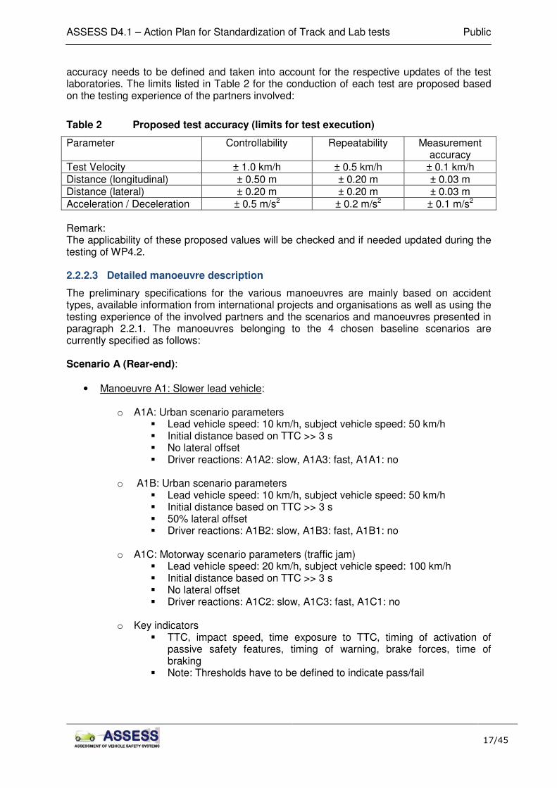
Test Velocity ± 1.0 km/h ± 0.5 km/h ± 0.1 km/h Distance (longitudinal) ± 0.50 m ± 0.20 m ± 0.03 m Distance (lateral) ± 0.20 m ± 0.20 m ± 0.03 m Acceleration / Deceleration ± 0.5 m/s2 ± 0.2 m/s2 ± 0.1 m/s2 Remark: The applicability of these proposed values will be checked and if needed updated during the testing of WP4.2. 2.2.2.3 Detailed manoeuvre description
The preliminary specifications for the various manoeuvres are mainly based on accident types, available information from international projects and organisations as well as using the testing experience of the involved partners and the scenarios and manoeuvres presented in paragraph 2.2.1. The manoeuvres belonging to the 4 chosen baseline scenarios are currently specified as follows: Scenario A (Rear-end):
• Manoeuvre A1: Slower lead vehicle:
o A1A: Urban scenario parameters � Lead vehicle speed: 10 km/h, subject vehicle speed: 50 km/h � Initial distance based on TTC >> 3 s � No lateral offset � Driver reactions: A1A2: slow, A1A3: fast, A1A1: no
o A1B: Urban scenario parameters � Lead vehicle speed: 10 km/h, subject vehicle speed: 50 km/h � Initial distance based on TTC >> 3 s � 50% lateral offset � Driver reactions: A1B2: slow, A1B3: fast, A1B1: no
o A1C: Motorway scenario parameters (traffic jam) � Lead vehicle speed: 20 km/h, subject vehicle speed: 100 km/h � Initial distance based on TTC >> 3 s � No lateral offset � Driver reactions: A1C2: slow, A1C3: fast, A1C1: no
o Key indicators � TTC, impact speed, time exposure to TTC, timing of activation of
passive safety features, timing of warning, brake forces, time of braking
� Note: Thresholds have to be defined to indicate pass/fail

ASSESS D4.1 – Action Plan for Standardization of Track and Lab tests Public
18/45
� Manoeuvre A2: Decelerating lead vehicle (until stopped):
o A2A: Urban scenario parameters (normal driving) � Initial Lead and Subject vehicle speed: 50 km/h � Initial distance: 14 m (1 sec following distance) � Lead breaking at 4 m/s2 � No lateral offset � Driver reactions: A2A2: slow, A2A3: fast, A2A1: no
o A2B: Urban scenario parameters (emergency braking lead) � Initial Lead and Subject vehicle speed: 50 km/h � Initial distance: 14 m (1 s following distance) � Lead breaking at 7 m/s2 � No lateral offset � Driver reactions: A2B3: fast, A2B1: no
o A2C: Motorway scenario parameters (normal driving) � Initial Lead and Subject vehicle speed: 80 km/h � Initial distance: 45 m (2 s following distance) � Lead breaking at 4 m/s2 � No lateral offset � Driver reactions: A2C2: slow, A2C3: fast, A2C1: no
o A2D: Motorway scenario parameters (emergency braking lead) � Initial Lead and Subject vehicle speed: 80 km/h � Initial distance: 45 m (2 s following distance) � Lead breaking at 7 m/s2 � No lateral offset � Driver reactions: A2D3: fast, A2D1: no
o Key indicators � TTC, impact speed, time exposure to TTC, timing of activation of
passive safety features, timing of warning, brake forces, time of braking
� Note: Thresholds have to be defined to indicate pass/fail
• Manoeuvre A3: Stopped lead vehicle:
o A3A: Urban scenario parameters � Subject vehicle speed: 50 km/h � Initial distance based on TTC >> 3 s � No lateral offset � Driver reactions: A3A2: slow, A3A3: fast, A3A1: no
o A3B: Urban scenario parameters � Subject vehicle speed: 50 km/h � Initial distance based on TTC >> 3 s � 50% lateral offset � Driver reactions: A3B2: slow, A3B3: fast, A3B1: no
o A3C: Motorway scenario parameters (traffic jam) � Subject vehicle speed: 80 km/h � Initial distance based on TTC >> 3 s � No lateral offset � Driver reactions: A3C2: slow, A3C3: fast, A3C1: no

ASSESS D4.1 – Action Plan for Standardization of Track and Lab tests Public
19/45
o Key indicators
� TTC, impact speed, time exposure to TTC, timing of activation of passive safety features, timing of warning, brake forces, time of braking
� Note: Thresholds have to be defined to indicate pass/fail Scenario B Junctions:
� Manoeuvre B1: Urban scenario 1:
o B1A: Open view � Subject vehicle speed: 50 km/h, Target vehicle speed: 10 km/h � Angle between Subject vehicle and Target Vehicle 90° � Initial distance: No reaction from Subject vehicle results in Euro NCAP
side � impact situation � Driver reactions: B1A2: slow, B1A3: fast, B1A1: no
o B1B: Distracted view � Subject vehicle speed: 50 km/h, Target vehicle speed: 10 km/h � Angle between Subject vehicle and Target Vehicle 90° � Obstructed view / Building 3.5 m away from both car centre lines � Initial distance: No reaction from Subject vehicle � results in Euro NCAP side impact situation � Driver reactions: B1B3: fast, B1B1: no
o Key indicators � TTC, impact speed, time exposure to TTC, timing of activation of
passive safety features, timing of warning, brake forces, time of braking
� Note: Thresholds have to be defined to indicate pass/fail � Manoeuvre B2: Urban scenario 2 (currently not feasible without C2C or C2I
communication):
o B2A: Open view � Subject vehicle speed: 50 km/h, Target vehicle speed: 50 km/h � Angle between Subject vehicle and Target vehicle 90° � Initial distance: No reaction from Subject vehicle results in Euro NCAP
side impact situation � Driver reactions: B2A2: slow, B2A3: fast, B2A1: no
o B2B: Distracted view � Subject vehicle speed: 50 km/h, Target vehicle speed: 50 km/h � Angle between Subject vehicle and Target vehicle 90° � Obstructed view / Building 3.5 m away from both car centre lines � Initial distance: No reaction from SV results in Euro NCAP side impact
situation � Driver reactions: B2B3: fast, B2B1: no
o Key indicators � TTC, impact speed, time exposure to TTC, timing of activation of
passive safety features, timing of warning, brake forces, time of braking

ASSESS D4.1 – Action Plan for Standardization of Track and Lab tests Public
20/45
� Note: Thresholds have to be defined to indicate pass/fail Scenario C (Oncoming traffic):
• Manoeuvre C1: Rural road:
o C1A: Safe speed � Subject and target vehicle speed: 40 km/h � Target not braking (?) � Initial distance based on TTC >> 3 s � 50% lateral offset � Driver reactions: C1A2: slow, C1A3: fast, C1A1: no
o C1B: Euro NCAP speed � Subject and target vehicle speed: 64 km/h (Euro NCAP speed) � Target avoiding accident last minute (? Testability under discussion) � Initial distance based on TTC >> 3 s � 50% lateral offset � Driver reactions: C1B2: slow, C1B3: fast, C1B1: no
o Key indicators � TTC, impact speed, time exposure to TTC, timing of activation of
passive safety features, timing of warning, brake forces, time of braking
� Note: Thresholds have to be defined to indicate pass/fail Scenario D (Cut-in):
• Manoeuvre D1: Oncoming cut-in:
o D1A: Intersection � Subject vehicle speed: 50 km/h; Target vehicle speed: 10 km/h � Cut-in distance: based on TTC = 3 s to reach 50% lateral offset at
moment of expected impact (if subject does not react) � Driver reactions: D1A2: slow, D1A3: fast, D1A1: no
o D1B: Intersection
� Subject vehicle speed: 50 km/h; Target vehicle speed: 10 km/h � Cut-in distance: based on TTC = 1 s to reach 50% lateral offset at
moment of expected impact (if subject does not react) � Driver reactions: D1B2: slow, D1B3: fast, D1B1: no
o Key indicators � TTC, impact speed, time exposure to TTC, timing of activation of
passive safety features, timing of warning, brake forces, time of braking
� Note: Thresholds have to be defined to indicate pass/fail
• Manoeuvre D2: Lane change cut-in:
o D2A: Motorway � Subject vehicle speed: 80 km/h; Target vehicle speed: 40 km/h � Full Lane change in 1 s � Cut-in distance: based on TTC = 1 sec to reach no lateral offset at
moment of expected impact (if subject does not react)

ASSESS D4.1 – Action Plan for Standardization of Track and Lab tests Public
21/45
� Driver reactions: D2A3: fast, D2A1: no
o D2B: Motorway � Subject vehicle speed: 80 km/h; Target vehicle speed: 40 km/h � Full Lane change in 2 s � Cut-in distance: based on TTC = 3 s to reach no lateral offset at
moment of expected impact (if subject does not react) � Driver reactions: D2B2: slow, D2B3: fast, D2B1: no
o Key indicators � TTC, impact speed, time exposure to TTC, timing of activation of
passive safety features, timing of warning, brake forces, time of braking
� Note: Thresholds have to be defined to indicate pass/fail
2.2.3 Explanation of selected conditions
The velocity of 50 km/h of the subject vehicle for all urban scenarios is based on the speed limit of 50 km/h which is valid within cities all over Europe. For the motorway manoeuvres except for manoeuvre A1C the target vehicle velocity is chosen to 80 km/h. This choice is made considering multiple aspects:
• The test needs to be safe for test drivers and the environment. Hence low test speeds are preferable over high test speeds.
• The test object should be crash-forgiving up to an impact speed of 80 km/h. Therefore all ∆v’s are tried to be kept lower or equal to 80 km/h.
• Additionally, motorway accidents are believed to most likely happen at crowded motorways where in general the maximum speed allowed is not reachable any more. A vehicle speed of 80 km/h is assumed valid traffic flow speed for crowed motorway scenarios.
For scenario C only two rural road manoeuvres are defined representing the target vehicle overtaking another vehicle for a longer time period, no sudden cut-in into the subject vehicle lane. Here the vehicle speed is chosen equal for both, Subject and Target vehicle. For manoeuvre C1A the speed is set to 40 km/h to limit the ∆v again to 80 km/h. As this test speed is considered as unreasonably low compared to real-world expected vehicle speeds, a second manoeuvre C1B with more realistic, Euro NCAP related, speeds is defined. However, the testability of this manoeuvre is under discussion as the ∆v of such a manoeuvre is too high to be manageable the target vehicle in case no evasive action is taken by the subject vehicle. The velocity of the target vehicle is highly depending on the chosen manoeuvre and varies from 0 km/h (A3 rear end accident with stopped target vehicle) over 50 km/h (B2 Intersection Urban accident) to 80 km/h (several A1 rear end motorway accidents). In general, the test speed of the target vehicle is chosen low for urban manoeuvres and higher for motorway manoeuvres. Deceleration of the target vehicle is only considered for the A2 (rear end accident, lead vehicle decelerating until stopped) manoeuvres. For all other tests the Target vehicle will always drive at constant speed. The initial overlap between Target and Subject vehicle is set to 0% for scenario D (cut-in), 50% for scenario C (oncoming traffic) and either 50% or 100% for scenario A (rear end). For scenario C no overlap is applicable as this is an intersection scenario. These values are based on the following assumptions: For scenario D no initial overlap can be present as both cars are travelling on different lanes at the beginning of the test. However, the target vehicle will move into the lane of the subject vehicle with an intended crash position of 50% or 100%

ASSESS D4.1 – Action Plan for Standardization of Track and Lab tests Public
22/45
overlap in case no action will be taken by the subject vehicle. No initial overlap between 0% and 50% is chosen in order to avoid system designs with a high potential for false alarms that might cause the driver to not react anymore to the system turn it off. Please note that all specifications such as speeds, decelerations and offsets still need to be confirmed by WP1 prior to the final test programme, as carried out in task 4.3. 2.2.4 Steps to final scenarios
In order to come to a final set of tests scenarios to be included in the test protocol, the proposed set of preliminary test specifications needs to be confirmed and or refined. Therefore, more detailed accident information than present in the deliverable “D.1.1 Preliminary Test Scenarios” is needed from WP1. Hence, the following actions will be taken by WP1 within task 1.2 in order to ensure a reasonable and realistic test programme for WP4:
• Establish more links between conflict situations and test scenario/ manoeuvres: A junction conflict could for example be covered under certain circumstances by a frontal test scenario.
• Determination of the relevance of the chosen manoeuvres based accident analysis.
• Ranking of the chosen scenarios and manoeuvres based on relevance in real world accidents using the 2-digit coding as used for the preliminary ranking as specified in Figure 1 (a & b).
• Verification or update of the chosen specifications as listed under 2.2.2.3 like vehicle speeds, lateral offset or TTC per manoeuvre.
• Advise to reduce the scenarios / manoeuvres to approximately 48 tests. The final test programme will be established within this work package based on the results of task 1.2 and the initial test programme as carried out in task 4.2.
2.3 Safety indicators
The proposed safety indicators as to be used during preliminary tests in task 4.2 are specified in Table 3. Regarding the information in this table to following remarks can be made:
• During the testing in task WP4.2 the feasibility and if needed limits of the various indicators will be investigated, with a special focus on the interaction with WP3 and WP5. After this testing a limited number of indicators will be used during the final testing of task 4.3.
• The measurement tools as proposed in the table are typical for outdoor testing using automatic vehicles. By the TNO VeHIL laboratory alternative tools will be used, such as the output of the dynamometer, but with compatible results and accuracy.
• During task 4.2 the proposed accuracy of the indicators will be checked in combination with the proposed accuracy limits as presented in Table 2.

ASSESS D4.1 – Action Plan for Standardization of Track and Lab tests Public
23/45
Table 3 Proposed Safety indicators
A1 A2 A3 B1 B2 C1 D1 D2
TTC Time To Collision
cars positions: 3cm
relative positions: 6cm
Speed: 0,1 Km/h
lattency: 10ms
Differentilal GPS (one per test vehicles,
target and subject)x x x x x x x x
TOW
Time Of Warning,
TTC at the moment of activation of
audio, visual or haptic warnings
Microphone: 5Khz
sampling
Video camera: 100 Hz
Accelerometer: 100 Hz
sensor according to warning; microphone,
video camera, accelerometer…x x x x x x x x
TOP
Time Of Protection,
TTC when activation of pasive safety
features
10 ms seatbelt tension sensor, accelerometer x x x x x x x x
TOA
Time Of Activation,
TTC at the moment of start or
automatical brake manoeuver of the
car
10 ms brake pressure sensor, accelerometer x x x x x x x x
MG
Maximal deceleration provided by
the car during automatical
deceleration
0,1 m/s2 accelerometer x x x x x x x x
MJMaximal Jerk at the moment of
applying the deceleration0,2 m/s3 post process of longitudinal acceleration x x x x x x x x
SR
Speed Reduction,
Automatic speed reduction provided
by the system before the impact
0,1 Km/h Differential GPS x x x x x x x x
IS
Impact Speed,
in case of dynamic target scenarios,
the impact speed will be the relative
speed between target and subject
vehicle
0,1 Km/h Front bumper contact sensor + Differential GPS x x x x x x x x
DR
Driver Reaction,
influence of driver reaction on the
system's action
10 msbrake pedal force sensor,
Steering wheel angle sensorx x x x x x x x
BF Brake Force applied by the driver 5 Nm brake pedal force sensor x x x x x x x x
DefinitionSafety IndicatorScenarios relevance
Measurement tools proposalMinimum accuracy
2.4 Test object
Part of the test specifications are the test or target objects. In ASSESS efforts will be made towards the development of objects meant for usage in consumer and regulatory testing. As such these objects may differ from tools used in development testing. For instance the test objects should be able to deal with all relevant types pre crash sensors used whereas in development testing objects for a specific sensor type may be used like radar reflectors. In the following section discusses aspects to be considered when defining the requirements and specifications for the test objects. 2.4.1 Type of object
For the evaluation of pre crash sensing systems different objects, each representing the various road users and its different sizes, could be used. The available budgets in ASSESS allow for the development of a single test object and the production of a limited number (maximum 4) of prototypes. Accident studies in WP1 revealed that car to car collisions are most relevant to be considered (Figure 1 (a & b)). During the WP4 Workshop held in November 2009 it was decided that the test object should represent a mid size car. Typical dimensions should be linked to a popular vehicle like e.g. the VW Golf or Opel Astra. 2.4.2 Propulsion system
As the target delivered by FTSS will not include a propulsion system, each laboratory needs to have an own propulsion system available when testing. The objects are to be mounted on propulsion systems available in / provided by the test labs. Two options are foreseen at the time being:
1) Suspended from a crane 2) Mounted on a carriage device
The crane system is operational at IDIADA. In this case the object is hanging on an arm mounted on a so-called rabbit vehicle. The figure below shows an example in a set-up for radar reflectors.

ASSESS D4.1 – Action Plan for Standardization of Track and Lab tests Public
24/45
Figure 6: IDIADA Rabbit vehicle carrying target for radar sensor
The second option is or will be available at TNO and BASt. TNO will use a device which is guided by rails on the floor. The device itself is currently being under design. Dimensions will be limited such that is will fit easily inside the test object. BASt is considering the use of a remotely controlled coasting platform of small dimensions. The Figure 9 below shows an example of such a coasting platform in a set-up with rear side of the vehicle mounted on top. Others laboratories like for instance Daimler have also experience with robot vehicles which are remotely controlled. These robot vehicles are flat and can be overrun by the test vehicle. This is not the case for the foreseen BASt and TNO carriage devices. This means that upon impact the carrying device may be decelerated severely. Test object cannot be design such as to completely avoid such excessive accelerations. This has to be discussed further more between FTSS, TNO and BASt. In case of an overrunable robot the test object should be attached with a release mechanism which allows the object to slide off from the robot under severe impact. As such a robot vehicle is overrunable the test vehicle or robot could be damaged in severe tests. FTSS will only deliver the object itself. The propulsion or “driving mechanism” has to be provided by the test labs. In order to guarantee the fitting the interface between the object and the propulsion system is part of the specifications (e.g. dimensions of the robot, location attachment and fixation points). BASt, TNO and Daimler will provide FTSS with dimensions of their carriage devices early in 2010. Based on this input the internal space for the carriage device will be specified. In addition to the internal dimensions requirements related to the stability of the object under accelerations need to be specified. During the ASSESS WP4 workshop November 2009 the following data were provided: � Maximum acceleration 5 g (~50 m/s2) / maximum deceleration 1 g (~10 m/s2) � When suspended from a crane the target should be stable in form up to 100 km/h:
Dynamic tilt (under accelerations) 10°, static tilt (constant velocity) 5°. � Allowable surface deformations under these accelerations (e.g. wrinkling of surface
cloth): unknown. Wrinkling may affect the performance for camera systems. However, it is not known to what extent.
� The colour of the test object should correspond with one of the most common (and perhaps challenging to detect) colour of the vehicles on the roads.
Further input to be provided by all partners during 1st half year 2010. 2.4.3 Sensor properties
As indicated the object should be applicable to the most relevant sensors currently used in pre crash sensing systems. As specified by ASSESS partners during the WP4 workshop November 2009 these are: Radar, lidar and camera.

ASSESS D4.1 – Action Plan for Standardization of Track and Lab tests Public
25/45
Radar: For the radar sensor the radar cross section (RCS) needs to be represented in a proper way. Based on previous testing experience Daimler recommended not to use corner reflectors as these do not properly deal with the 3-D effect of the vehicle (different cross section when looking from different angle / distance, influence of reflections from vehicle bottom, etc.). Instead it is preferred to have the reflective material integrated in the surface of the object such that the RCS is representative “all surround”. As far as the details of the RCS values are concerned, TNO via its PreScan simulation tool will provide input in the 1st half of 2010. Daimler presumably can provide input of actual vehicle measurements via a 360° scan of the radar reflectance of a real vehicle in summer 2010. Camera: A first set of properties related to cameras was provided by IDIADA during the WP4 workshop. Apart from the vehicle dimensions and surface reflection properties, details on the vehicle are to be included e.g.: � Transparent zones must be included to represent the windows. The area and location
should relate to the selected vehicle size. � Rear lights reflective materials should be included. � Ideally active (operating) brake lights and turn light indicators should be integrated to the
target vehicle (useful for cut-in and target braking scenarios). � Number plates must be included. � If the target vehicle is carried by a lorry / crane the target should be suspended close to
the ground surface (e.g. ~5 cm) and if possible include a dark part at its bottom to simulate the shadow below a vehicle (if the target does not by itself generate a shadow).
Figure 7: Requirements for camera: transparent zone, lights, number plate
As mentioned above it might be important for the camera (as well as for the radar and the lidar) to have limited deformation of the target. Especially in cases where the target is moving in a bend the outer surface, which has to be of soft material because of the crash forgivingness, may deform or wrinkle (see Figure 8). In such case problems may be introduced for sensor algorithms that assume fixed points on a “rigid” target.

ASSESS D4.1 – Action Plan for Standardization of Track and Lab tests Public
26/45
Figure 8: Possible deformation of a balloon car: Balloon car tests by Ford (left) and Autoliv (right)
Lidar: Lidar properties have not been discussed so far but basically reflection of the surface and dimensions are the key properties to be considered for these sensors. TNO, e.g. via IBEO, may provide detailed input on the reflective properties related to laser scanners.
2.4.4 Crash forgivingness
The test object is meant to do repeated tests with vehicles evaluating the pre-crash sensor system. Although detailed specifications of the tests are still being prepared differences in the absolute test speed of up to 80 km/h may be expected. Under these conditions the test objects should survive a sufficient amount of tests and it should not introduce damage to the vehicle. For some test scenarios it could be necessary to release the test target from the propulsion system. This could be necessary at a certain impact speed during the crash to keep the tested vehicle, the test object and the propulsion system safe. This depends on the overall weight of the test object and the used propulsion system and has to be discussed further more during the project. The number of tests that it should survive is yet to be defined but should be in the range of 100 tests. 2.4.5 Concepts
In the field three different concepts are being used for the test objects:
1) Balloon cars 2) Flat (foam) objects 3) Sensor specific objects like radar reflectors
As mentioned before the sensor specific objects are not applicable for regulatory and consumer testing. Also during discussions on the test objects (WP4 Workshop November 2009) it was forwarded that balloon cars are strongly preferred because as some of the scenarios will introduce combined front, side or rear / side views on the test object. This is difficult to achieve in a realistic way when using 2-D objects. Therefore the balloon car concepts will be further explored (see also Figure 8). The balloon car should consist of a stiff carrying structure surrounded by a soft, crash-forgiving, part. The stiffer structure may be realized by using tubes typically used in river rafts. The soft exterior structure may be realized by airbag cloth. By using internal straps the geometry may be shaped.

ASSESS D4.1 – Action Plan for Standardization of Track and Lab tests Public
27/45
3 Laboratory updates
3.1 General requirements
The goal of this WP is amongst others to develop a test procedure that can be conducted in more than one test laboratory independent of general boundary conditions as indoor / outdoor testing, level of testing experience or amount of proving grounds. The majority of test scenarios should be feasible in all test facilities hence allowing an independent assessment of the safety systems. Therefore, within this project not only one but three test laboratories (IDIADA, TNO and BASt) with different kind of test methods, testing experience and proving grounds are considered. The current TNO test laboratory called VeHIL (Vehicle Hardware in the Loop) is an indoor test facility that uses a stationary bullet vehicle on a dynamometer and a so called “moving base” as test object. At IDIADA and BASt bullet vehicles run on outdoor tracks with very different boundary conditions and with the target vehicle either having an own propulsion system or being carried by a moving crane. Furthermore the experience levels in testing active safety systems at the different test laboratories are different. The most experience is probably with IDIADA, who is also active in performing several development tests for the car industry. TNO’s VeHIL is a relatively new test laboratory with a new approach based on testing with relative speeds and medium experience. BASt on the other hand is currently building up its experience and equipment for tests of active safety systems with access to various large test grounds but not yet to target propulsion systems. As the target delivered by FTSS will not include a propulsion system, each laboratory needs to have an own propulsion system available when testing. As the different laboratories will be working under consideration of different general boundary conditions (BASt and IDIADA will for example test outside whereas all tests at TNO will be conducted inside), this propulsion system does not necessarily need to be similar at each test site. The technical solution is hence allowed to be different per laboratory. The final selection of the propulsion system will be done in task 4.2. The established preliminary test programme includes up to 3 different kinds of driver reactions per manoeuvre. To ensure that this driver reaction will be implemented into each test set up in a robust and repeatable manner, the subject vehicle needs to be equipped with a brake robot that is able to react according to the specifications that will be established by WP3 for a fast and slow reacting driver. To ensure that the majority of the test programme can be conducted by each test site at the end of task 4.2, the estimated costs for the planed updates need to be feasible. However it should be noted, that not all costs for the planned updates will be covered within the ASSESS project. Apart from the specifications mentioned above and as mentioned already before in chapter 2 also the following general requirements shall be met by all laboratories:
o Safe testing for test driver, tested object and environment o Ability to conduct the majority of tests defined in the final test program o Repeatable and Reproducible testing within the limits defined in Table 2 o Time efficient testing within a reasonable time frame o Cost efficient testing o Ability to record environmental test conditions

ASSESS D4.1 – Action Plan for Standardization of Track and Lab tests Public
28/45
3.2 Specifications / current situation
According to the experience levels described in chapter 3.1 the following chapters describe the current status and approaches of the three test laboratories involved. 3.2.1 BASt
At the time being, BASt is equipped with high-precision measurement equipment and has access to various test tracks. It is up to now not equipped with a dummy target nor a target propulsion system. The test tracks available for ASSESS are summarized in Table 4.
Table 4 Test tracks
Name Description Location Availability Cost BASt FTVA Circular track,
diameter 80 m Bergisch Gladbach (BASt)
Restricted
CGN Airfield Taxi way at Köln/Bonn airfield, 1000x15 m
Cologne
Griesheim Airfield
1200x20 m Darmstadt (200 km away from BASt)
German Army Proving Ground
500x80 m Trier (200 km away from BASt)
Sperenberg Airfield
Former Soviet Airfield, 2500x40 m
Sperenberg/Berlin (600 km away from BASt)
The measurement equipment consists of two synchronized fiber-optical gyros with GPS support and differential GPS (DGPS). Accuracy even in dynamic driving situations (> 50 km/h) is better than 2,5 cm (tested precision, nominal accuracy during these driving situations is 1 cm). This system can easily be mounted on any car and delivers position, velocity and acceleration data. Additional light switches without time delay help to synchronize measurements and experiment design. 3.2.2 TNO
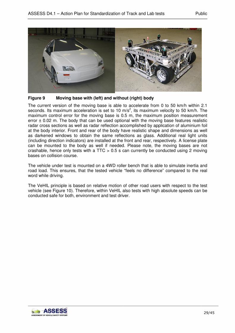
The current TNO test site called VeHIL (Vehicle Hardware in the Loop) is an indoor test track that allows for reproducible, effective, safe and efficient testing of active safety systems for intelligent vehicles on different levels. So far, within VeHIL only the so called “moving base” is used as test object (see Figure 9). This robot vehicle has 4 independently driven wheels that allow for motion a normal car would not be able to conduct (as for example lateral movement or spinning).

ASSESS D4.1 – Action Plan for Standardization of Track and Lab tests Public
30/45
Figure 10 VeHIL motion principle
VeHIL does allow for both, open loop as well as closed loop testing (see Figure 11). For closed loop testing, the speed of the test vehicle is processed real time by the so called MARS unit (Multi Agent Real-time Simulator) and translated to the real world situation. From there, MARS feeds back all necessary information to the moving base resulting in an adaption of the moving bases’ speed according to the actions taken by the car on the roller bench.

ASSESS D4.1 – Action Plan for Standardization of Track and Lab tests Public
31/45
Figure 11 VeHIL: closed loop test set up including all acting components
3.2.3 IDIADA
The objective of the ADAS (Advanced Driver Assistance Systems) testing tools is a reproduction of real-life traffic situations, where different cars interact with each other. Due to the intrinsic danger of such situations, a system which allows reproduction of the required scenarios has been developed in order to perform testing activities in a safe and realistic environment. The different targets are created for each specific scenario (rear end, junction, oncoming traffic,…) which depend on the required target speed (static or dynamic) and the type of sensor detection (radar, lidar or camera). The current testing tools are detectable by: Radar sensors: Using a combination of metallic films and corner reflectors is obtained the radar properties of the target vehicle. The corner reflector object is made using a plastic corners reflector and a metal foil matching the reflective properties of a standard vehicle has been pasted on the plastic surface. When radar waves are beamed at a target, only certain amounts are reflected back. A number of different factors determine how much electromagnetic energy returns to the source. RCS (Radar Cross Section) is a measure of how detectable an object is with radar. A larger RCS indicates that an object is more easily detected. The corner reflectors used in the target can measure:
� RCS: 10 m² ± 3 m² (based on ISO standard)

ASSESS D4.1 – Action Plan for Standardization of Track and Lab tests Public
32/45
Figure 12: Radar Cross Section
Lidar sensors: LIDAR (Light Detection and Ranging; or Laser Imaging Detection and Ranging) is a technology that determines distance to an object or surface using laser pulses. Lidar Target consists on reflective surfaces fixed on the target vehicle simulation panel. These reflective surfaces have the following dimensions:
� Rear reflective surface: 3 x 20 cm² ± 5 cm² (based on ISO standard)
Camera sensors: The simulation panel of the target vehicle needs to reproduce a real standard vehicle shape visible by camera detection; the dimensions and main characteristics are the following:
• Height (Medium values for D segment cars): h = 1.5 m ± 0.5 m
• Width: w = 1.8 m ± 0.5 m (frontal an rear view) w = 3.5 m ± 0.5 m (side view)
• Ideally the target shall be similar to a scale 1:1 car picture
• Number plate: with standard size picture with characters (frontal and rear view)
• Rear light: 2x 300 cm² ± 50 cm² (frontal and rear view) The main testing tools (Rabbit vehicle, Balloon car and Intersection vehicle) are described below: Dynamic Target Vehicle or Rabbit Vehicle
The dynamic target vehicle or Rabbit vehicle is a vehicle that is approaching the vehicle equipped with ADAS systems from front, behind or side which are considered coverage detection zones. The target needs to be detectable by the system sensors (radar, lidar and camera) and crashable in case of system failure. The Rabbit vehicle is a vehicle equipped with a metal structure suspended from the roof which carries a reproduction of the vehicle simulation panel (object vehicle).
Figure 13: Dynamic Target Vehicle or Rabbit Vehicle
The test manoeuvres normally require vehicles to follow each other or approach very close, often at high speeds. Due to this, Rabbit Vehicle is a vehicle with good dynamic behaviour, stable straight line driving, powerful brakes and engine, and the metallic structure is designed to support the vehicle simulation panel.

ASSESS D4.1 – Action Plan for Standardization of Track and Lab tests Public
33/45
This simulation panel acts as the target for the sensor systems of the vehicle under test. Three configurations (depending on the position of the panel) are possible, allowing a wide range of tests to be performed:
• In straight line (target vehicle approaching from the front part of the test vehicle)
Figure 14: On-coming traffic configuration, rear end (radar configuration), rear end (all sensors configuration)
• In the side line (target vehicle approaching from the side part of the test vehicle)
Figure 15: Side detection configuration
• In straight line (target vehicle approaching from the rear part of the test vehicle)
Figure 16: Rear detection configuration
Three kinds of simulation panels are used to implement the tests. The simulation panels are front, rear and side images of one standard vehicle. Target main characteristics of the Rabbit vehicle in dynamic conditions are:
• Max target speed: max 100 km/h ±10 km/h
• Target acceleration / deceleration : 0.2 m/s² / 8 m/s²
• The target does not damage the test vehicle if an impact occurs.
• Target impact speed (Delta speed impact): maximum 40 km/h
• Lateral Offsets (0 – 100 %)

ASSESS D4.1 – Action Plan for Standardization of Track and Lab tests Public
34/45
Figure 17: Rear detection test
The other issues of highest importance are accuracy and repeatability performance of the test manoeuvres. Hence accurate Inertial GPS Navigation Systems are used for high accuracy measurements of various physical parameters like position (x, y and z), velocities (x, y and z), and accelerations (x, y and z) etc. These systems can be fixed on both the vehicle for recording relative measurements such as relative displacement (x, y and z), relative velocities (x, y and z), and relative accelerations (x, y and z), etc.
Figure 18: Physical parameters
Inertial GPS Navigation System
The Inertial and GPS navigation system is an advanced six-axis inertial navigation system that incorporates an L1/L2 RTK GPS receiver and delivers better than 0.02 m RMS positioning under dynamic conditions using differential corrections. The outputs from the Inertial and GPS navigation system are derived from the measurements of the accelerometers and gyros. Using the inertial sensors for the main outputs give the system a fast update rate (100 Hz) and a wide bandwidth. All the outputs are computed in real-time with a very low latency. The inertial and GPS navigation system is used for two functions: Accurate (3 cm) measurement of the relative motion between two vehicles. All measurements are online, in real-time and output on a CAN bus, including the target vehicle measurements being relayed to the subject vehicle's CAN bus.
Figure 19: Inertial GPS navigation system
For accurate repeatability steering, braking and throttle robots can be installed in the Rabbit vehicle which can be interfaced with the on-board GPS navigation system to drive the vehicle

ASSESS D4.1 – Action Plan for Standardization of Track and Lab tests Public
35/45
through a pre-defined course over the ground with high precision, leading to a positioning error of less than 3 cm.
For this, use of driving robots allows high accuracy controlled path and movement applied to the rabbit using Differential GPS. Manoeuvres such as lane change, overtaking or curve scenarios can be done with a high accuracy and repetitiveness. Braking Robot System
The Brake Robot is designed to apply inputs to a vehicle's brake pedal for braking characterization and handling behaviour measurement. It is typically used to apply step or ramped force or position inputs to the brake pedal.
Figure 20: Braking Robot System
Accelerator Robot System
The AR series Accelerator Pedal Robot is designed to apply inputs to a vehicle’s throttle pedal for closed loop vehicle speed control.
Figure 21: Accelerator Robot System
Steering Robot System
The SR30 Steering Robot or the programmable steering controller is designed to apply inputs to a vehicle’s steering system through a closed loop control.
Figure 22: Steering Robot System
Static Target Vehicle or Balloon Car
In static conditions, a foam impact cube is used as a static target vehicle. This target object is used as static obstacle that can be crashed at speeds up to 80 km/h.

ASSESS D4.1 – Action Plan for Standardization of Track and Lab tests Public
36/45
Figure 23: Balloon Car
The main characteristics of the Balloon car are:
• Detectable by Radar, Lidar and camera.
• The target does not damage the test vehicle if an impact occurs.
• Target impact speed (Delta speed impact): maximum 80 km/h
• Lateral Offsets (0 – 100 %) Dynamic Target vehicle for Intersection tests scenarios (Intersection Vehicle)
Figure 24: Dynamic Target vehicle for Intersection tests
The silhouette is made of foam and will come lose when contact takes place, this makes crashing into it safe (if the system fails). No damage will be caused to the vehicle under test. A picture of a vehicle is put on the side where the test vehicle is coming from and on the other side the detection equipment.
Figure 25: Dynamic Target vehicle in intersection test
This equipment is mounted onto a cable car which holds the Silhouette stable during the test, the cable car is mounted on cable rails, which are held in place by two pillars on both ends and the cable car is set in motion by an electric motor on one end of the pillar.

ASSESS D4.1 – Action Plan for Standardization of Track and Lab tests Public
37/45
The system actuates automatically when the test vehicle passes the light barrier sensor (which calculates the test vehicle speed), this will send a signal to the motor which actuates and moves the silhouette from the right to the left position or vice versa. Calculations are made to make sure that the silhouette is in a chosen position of the intersection when test vehicle arrives.
Figure 26: Control system software
Current Specifications versus draft test scenarios: Taking into account the actual specifications and characteristics of IDIADA test tracks and testing tools, IDIADA is able to develop an important range of manoeuvres defined in the draft test scenarios A, B, C and D. 3.2.4 General required equipment
In order to be able to perform all tests specified within Section 2.2.2.2, some general equipment is needed by each laboratory. In Table 5 all general items that are necessary for successful testing of the chosen manoeuvres are listed. For all laboratories it is indicated, if the respective items are:
o already fully functional (+) o will need to be updated (u) o is not necessary for this laboratory (-) o needs to be rented, built or bought (b) o developed within the ASSESS project (a)
Table 5 General equipment needed for conduction of the test program
General equipment BASt IDIADA TNO Measurement system + + + Software u u u General propulsion system b/a u/a a/u Crane attachments -/b/a u/a - Test ground +/b + + Target4 a a a Braking robots b + u Steering robots b + - Accelerator robots - + - Autonomous driving - b - Data acquisition u b u
4 The target will be built by FTSS and provided to all 3 test laboratories

ASSESS D4.1 – Action Plan for Standardization of Track and Lab tests Public
38/45
3.3 Planned updates
3.3.1 BASt
Restricted 3.3.2 TNO
Restricted 3.3.3 IDIADA
Restricted
3.4 Status of test program after update
In Table 6 all manoeuvres of the preliminary test program as well as their conductibility per laboratory is listed respectively. A “+” indicates, that after the update is completed the respective laboratory will be able to conduct the test where a ”-” indicates that it will still not be able to conduct that specific manoeuvre. In case of a “o” reading the laboratory might not be able to conduct the respective manoeuvre under all circumstances.
Table 6 Test-program and status of possible conduction after laboratory update per laboratory
Manoeuvre BASt IDIADA TNO A1A + + + A1B + + + A1C o o + A2A + + + A2B + + + A2C o o + A2D o o + A3A + + + A3B + + + A3C o + + B1A + + o B1B + + o B2A + + o B2B + + o C1A o + + C1B o o o D1A o + + D1B o + + D2A + + + D2B + + +

ASSESS D4.1 – Action Plan for Standardization of Track and Lab tests Public
39/45
The following risks / challenges are established and considered during the update and the conduction of the test program by each test laboratory: Restricted
3.5 Budget
3.5.1 BASt
Restricted 3.5.2 TNO
Restricted 3.5.3 IDIADA
Restricted

ASSESS D4.1 – Action Plan for Standardization of Track and Lab tests Public
40/45
4 Test planning
4.1 Task 4.2: Improvement and standardization of existing test methods
Task 4.2 runs from Month 7 to Month 18. The work programme is equally split into two parts, preparation of preliminary tests and conduction of preliminary tests. During the first part (M7 to M14), the test labs will be updated with equipment, the standard target will be delivered, and the methodology will be developed. After the preparation is completed and all labs are ready, from M13 to M18 preliminary tests with production cars from Daimler and Toyota will be conducted. An overview on the test method definition is presented in Table 7.
Table 7 Overview on test preparation and preliminary tests
Test Preparation M07 – M14 � Standardisation of Test Methods, based on T 4.1 specifications M07 – M12 � Scenarios � Targets (Standardise test objects, cross sections etc.) � Methodology Development M07 – M12
� Initial and boundary conditions data recording etc � Defining the essential set of variables to measure � Establishing criteria for successful passing of the tests
� TUG will provide safety routines for all test tracks � Labs will be updated (e.g. Hardware, software) according to T4.1
specifications M07 – M12 � FTSS delivers standard test object M07 – M14
Conduction of Preliminary Tests M13 – M18 � Tests with production cars from Daimler and Toyota M13 – M18 � Track test 1 / IDIADA, Spain � Track test 2 / BASt, Germany � Laboratory test 1 / TNO, the Netherlands

ASSESS D4.1 – Action Plan for Standardization of Track and Lab tests Public
41/45
4.2 Task 4.3: Evaluation of test and assessment methods and protocols
The evaluation of test and assessment methods will start in M18. And overview on the Test Series is presented in Table 8, the timeline and assignment of cars to labs is shown in Table 9.
Table 8 Overview over the Test Series in Task 4.2
Carlab I (IDIADA) will be ready by M18
Test Series 1: � Vehicle A (Daimler) and Carlab I will be tested in all three laboratories
(~3 weeks/laboratory) M18 – M23 � Full set of scenarios � Evaluation of Test Results (IDIADA, all) M24
� Checking the test results against system specifications of WP1 � Defining of output of the results to be supplied to WP5 � Specifying potential updates for the methods and/or evaluation methods � Defining a reduced number of WP1 scenarios for test series 2 � Validation of WP3 simulator tests (IDIADA)
Carlab II (TNO) will be ready by M24
Test Series 2: � Vehicle B (Toyota) and Carlab II will be tested in all three laboratories
(~3 weeks/laboratory) M24 – M26 � Reduced number of test scenarios � Evaluation (IDIADA, all) M27 – M28 � Defining of final output of results to be supplied to WP5 � Defining a final draft and assessment protocol

ASSESS D4.1 – Action Plan for Standardization of Track and Lab tests Public
42/45
Table 9 Timeline for Tasks 4.2 and 4.3, including Milestones / Deliverables and assignment of cars to the labs (for full titles of Milestones / Deliverables see Table 1)
Restricted

ASSESS D4.1 – Action Plan for Standardization of Track and Lab tests Public
43/45
Links to other WPs
The most important links from WP4 to other WPs are the links to WP1, WP2, WP3 and WP5. These are summarized in Table 10.
Table 10 Links to WP1, WP2, WP3 and WP5
WP1: More detailed accident information for WP4 is needed from WP1 in order to ensure a reasonable and realistic test programme for WP4:
• Establish more links between conflict situations and test scenario/ manoeuvres: A junction conflict could for example be covered under certain circumstances by a frontal test scenario
• Determination of the relevance of the chosen manoeuvres based accident analysis
• Ranking of the chosen scenarios and manoeuvres based on relevance in real world accidents using the 2-digit coding as used for the preliminary ranking as specified in Figure 2
• Verification or update of the chosen specifications as listed under 2.2.2.3 like vehicle speeds, lateral offset or TTC per manoeuvre
• Advise to reduce the scenarios / manoeuvres The final test programme will be established within this work package based on the results of task 1.2 and the initial test programme as carried out in task 4.2. WP2: Calculated severity reductions of accidents/injuries in the selected scenarios from WP4 and WP5 deliver input for WP2’s socio-economic impact assessment of the selected safety systems.
WP3: M3.2 Experimental studies completed, documented and available [M20] (TOYOTA) D3.2 Report on the experimental study results of the evaluation of behavioural aspects - (TOYOTA) [M20] In almost all test scenarios, driver reaction is taken into account. Therefore, the findings from WP3 are eminent for the final definition of test scenarios. These findings will be available not earlier then M20. The additional information on driver reaction and interaction during track testing will be fed back to WP3.
WP5: D5.1 Description of the impact conditions for the crash performance evaluation of the pre-crash systems and the possible means to evaluate them. (IDIADA) [M18] In M18, preliminary testing is done. Obtained early raw data on speed reduction during the pre-crash phase will be supplied to WP5 for deliverable D5.1. D5.2 Draft test and assessment protocol for the evaluation of the influence of the pre-crash systems during the crash phase including complete simulation and sled testing methodologies and strategies for full crash testing. (IDIADA) [M32] The influence of pre-crash systems on crash performance, e.g. speed reduction during the pre-crash phase is the main outcome of WP4 and will be supplied to WP5 after completion of WP4.

ASSESS D4.1 – Action Plan for Standardization of Track and Lab tests Public
44/45
5 Risk Register
5 Risk level: 1 = high risk, 2 = medium risk, 3 = Low risk
Risk No.
What is the risk Level of risk5
Solutions to overcome the risk
WP4R1 Test Reproducibility & Repeatability at one lab not sufficient
Medium Test conduction is shifted to two other labs
WP4R2 Test R&R at two labs not sufficient Low At least two labs are needed for test conduction. In this case, another partner would have to be brought in
WP4R3 Test Vehicles damaged Medium
WP4R4 Standard Target destroyed Medium
WP4R5 Test planning subject to change due to weather conditions
Medium
WP4R6 Standard Test Object not delivered in time
Medium Delay in Task 4.2 and 4.3
ASSESS D4.1 – Action Plan for Standardization of Track and Lab tests Public
45/45
6 Conclusion
This deliverable of WP4.1 is the starting point of this working package and therefore essential for any further activities. Clear guidelines are needed and links to other relevant WPs have to be defined. As the complete ASSESS project is still in the starting phase some information is still outstanding and has to be included in the project documentation at a later stage. In principle this document provides all the information necessary for further activities. Starting with the overall accident situation on the roads in Europe delivered from WP1 and the therewith caused total injury costs, a set of relevant accident situations and related test scenarios was compiled. The number of selected relevant scenarios is 48, including scenarios that are probably not activating the selected safety systems. These scenarios have been included in order to provide a challenging set of test cases and in order to set the bases for a test plan that will cope with expected evolutions of considered systems. To ensure that the proposed parameters of each test scenario are relevant and realistic, WP1.2 will perform an in-depth analysis for these specific configurations. Unfortunately there might not be sufficient in-depth accident data available to give a statistical confirmation, but it might support the proposed parameters which were defined by engineering judgment.