European Aviation Safety Agency · TCDS No.:EASA.R.105 Type Page 1 of 45 Issue: 01 Date: 7 January...
45
TCDS No.:EASA.R.105 Type Page 1 of 45 Issue: 01 Date: 7 January 2014 TE.TC.0066-001 © European Aviation Safety Agency, 2014. All rights reserved. Proprietary document. Printed copies are not controlled. Confirm revision status through the EASA-Internet/Intranet. European Aviation Safety Agency EASA TYPE-CERTIFICATE DATA SHEET No. EASA.R.105 for DAUPHIN Type Certificate Holder AIRBUS HELICOPTERS Aéroport International Marseille – Provence 13725 Marignane cedex France For Models: SA 365 C SA 365 C1 SA 365 C2 SA 365 N SA 365 C3 AS 366 G1 SA 365 N1 AS 365 N2 AS 365 N3 EC 155 B EC 155 B1
Transcript of European Aviation Safety Agency · TCDS No.:EASA.R.105 Type Page 1 of 45 Issue: 01 Date: 7 January...

TCDS No.:EASA.R.105 Type Page 1 of 45 Issue: 01 Date: 7 January 2014
TE.TC.0066-001 © European Aviation Safety Agency, 2014. All rights reserved.
Proprietary document. Printed copies are not controlled. Confirm revision status through the EASA-Internet/Intranet.
European Aviation Safety Agency
EASA
TYPE-CERTIFICATE DATA SHEET
No. EASA.R.105
for DAUPHIN
Type Certificate Holder AIRBUS HELICOPTERS
Aéroport International Marseille – Provence
13725 Marignane cedex France
For Models: SA 365 C SA 365 C1 SA 365 C2 SA 365 N SA 365 C3 AS 366 G1 SA 365 N1 AS 365 N2 AS 365 N3 EC 155 B EC 155 B1

TE.TC.0066-001 © European Aviation Safety Agency, 2014. All rights reserved.
Proprietary document. Printed copies are not controlled. Confirm revision status through the EASA-Internet/Intranet.
Intentionally left blank

TCDS No.: EASA.R.105 Type Page 3 of 45 Issue: 01 Date: 7 January 2014
TE.TC.0066-001 © European Aviation Safety Agency, 2014. All rights reserved.
Proprietary document. Printed copies are not controlled. Confirm revision status through the EASA-Internet/Intranet.
TABLE OF CONTENTS
SECTION 1: MODEL SA365 C, C1, C2, C3 : ......................................................................................... 4
I. GENERAL ......................................................................................................................... 4 II. CERTIFICATION BASIS ...................................................................................................... 5 III. TECHNICAL CHARACTERISTICS AND OPERATIONAL LIMITATIONS ........................................ 5 IV. OPERATING AND SERVICE INSTRUCTIONS ........................................................................ 8 V. NOTES ..........................................................................................................................10
SECTION 2: MODEL SA365N, N1, AS365 N2, N3 .............................................................................. 11
I. GENERAL ........................................................................................................................11 II. CERTIFICATION BASIS .....................................................................................................12 III. TECHNICAL CHARACTERISTICS AND OPERATIONAL LIMITATIONS .......................................13 IV. OPERATING AND SERVICE INSTRUCTIONS .......................................................................18 V. NOTES ..........................................................................................................................20
SECTION 3: MODEL SA366G1 ........................................................................................................... 22
I. GENERAL ........................................................................................................................22 II. CERTIFICATION BASIS .....................................................................................................22 III. TECHNICAL CHARACTERISTICS AND OPERATIONAL LIMITATIONS .......................................23 IV. OPERATING AND SERVICE INSTRUCTIONS .......................................................................27 V. NOTES ..........................................................................................................................28
SECTION 4: MODEL EC155 B ............................................................................................................. 29
I. GENERAL ........................................................................................................................29 II. CERTIFICATION BASIS .....................................................................................................29 III. TECHNICAL CHARACTERISTICS AND OPERATIONAL LIMITATIONS .......................................31 IV. OPERATING AND SERVICE INSTRUCTIONS .......................................................................34 V. NOTES ..........................................................................................................................36
SECTION 5: MODEL EC155 B1 ........................................................................................................... 37
I. GENERAL ........................................................................................................................37 II. CERTIFICATION BASIS .....................................................................................................37 III. TECHNICAL CHARACTERISTICS AND OPERATIONAL LIMITATIONS .......................................39 IV. OPERATING AND SERVICE INSTRUCTIONS .......................................................................42 V. NOTES ..........................................................................................................................44
SECTION 6: ADMINISTRATIVE ........................................................................................................... 45
I. ACRONYMS AND ABBREVIATIONS ......................................................................................45 II. TYPE CERTIFICATE HOLDER RECORD ..............................................................................45 III. CHANGE RECORD ..........................................................................................................45

TCDS No.:EASA.R.105 Type Page 4 of 45 Issue: 01 Date: 7 January 2014
TE.TC.0066-001© European Aviation Safety Agency, 2014. All rights reserved. Proprietary document. Printed copies are not controlled. Confirm revision status through the EASA-Internet/Intranet.
SECTION 1: MODEL SA365 C, C1, C2, C3 :
I. General
1. Type/ Model/ Variant
1.1 Type SA 365
1.2 Model SA 365 C, C1, SA 365 C2, SA 365 C3
1.3 Variant N/A
2. Airworthiness Category Large Rotorcraft, Category A and B
3. Manufacturer
before January 1, 1992 AEROSPATIALE
before January 7, 2014 EUROCOPTER
since January 7, 2014 AIRBUS HELICOPTERS
Aéroport International Marseille-Provence
13725 MARIGNANE cedex
4. EASA Type Certification Application Date Note: State of Design Authority certification application date for grandfathered products
SA 365 C 14 November 1974
SA 365 C1 23 March 1979
SA 365 C2 15 October 1979
SA 365 C3 23 June 1981
5. State of Design Authority
DGAC-France
6. State of Design Authority Type Certificate Date
SA 365 C 4 July 1978
SA 365 C1 26 March 1979
SA 365 C2 18 February 1980
SA 365 C3 14 January 1982
7. EASA Type Certification Date N/A (to DGAC France)

TCDS No.:EASA.R.105 Type Page 5 of 45 Issue: 01 Date: 7 January 2014
TE.TC.0066-001© European Aviation Safety Agency, 2014. All rights reserved. Proprietary document. Printed copies are not controlled. Confirm revision status through the EASA-Internet/Intranet.
II. Certification Basis
1. Reference Date for determining the applicable requirements: 14, November 1974
2. Airworthiness Requirements FAR Part 29 Amendments 1 through 11
3. Special Conditions Complementary and special conditions defined in DGAC letter 4092 dated May 5, 1977
4. Exemptions None.
5. (Reserved) Deviations None.
6. Equivalent Safety Findings None.
7. Environmental Protection Requirements None.
III. Technical Characteristics and Operational Limitations
1. Type Design Definition
SA 365 C basic definition described in document 365A 04 3051
SA 365 C1 definition of SA 365 C1 is obtained by applying to the SA 365 C definition the modifications mentioned in document 365A.05.0416
SA 365 C2 definition of SA 365 C2 is obtained by applying to the SA 365 C or C1 definition the modifications mentioned in document 365A.05.0425
SA 365 C3 definition of SA 365 C3 is obtained by applying to the SA 365 C1 or C2 definition the modifications mentioned in document 365A.04.3765
2. Description
Large twin-engine helicopter
3. Equipment
N/A
4. Dimensions
4.1 Fuselage Width 3.17 m (10,40 ft)
Height 3.27 m (10.72 ft)
Length 10.98 m (36.02 ft)
4.2 Main Rotor Diameter 11.68 m (38.31 ft)
4.3 Tail Rotor Diameter 0.89 m (2.95 ft)
5. Engine
5.1 Model
SA 365 C 2 TURBOMECA ARRIEL 1A
SA 365 C1 2 TURBOMECA-ARRIEL 1A1
SA 365 C2 2 TURBOMECA-ARRIEL 1A2
SA 365 C3 2 TURBOMECA-ARRIEL 1C

TCDS No.:EASA.R.105 Type Page 6 of 45 Issue: 01 Date: 7 January 2014
TE.TC.0066-001© European Aviation Safety Agency, 2014. All rights reserved. Proprietary document. Printed copies are not controlled. Confirm revision status through the EASA-Internet/Intranet.
5.2 Type Certificate
Engines TCDS E.073
5.3 Limitations 5.3.1 Installed Engine Limits Refer to approved Flight Manual 5.3.2 Transmission Torque Limits Refer to approved Flight Manual
6. Fluids (Fuel/ Oil/ Additives)
6.1 Fuel
as approved in the Flight Manual
6.2 Oil
as approved in the Flight Manual
6.3 Additives
as approved in the Flight Manual
7. Fluid capacities
7.1 Fuel
640 l (169 US gals)
usable 637 l (168 US gals)
7.2 Oil
Engines 2 x 6.8 l (oil tank)
MGB 10.5 l
TGB 0.27 l
7.3 Coolant system capacity
RH system 7 l
LH system 7 l
8. Air Speeds Limits
Vne 315 km/h (170 kts) at 0 m at 3000 kg
Substract 20 km/h per 1000 m altitude, and
10 km/h per 100 kg above 3000 kg
see Flight Manual for other approved airspeed limits
9. Rotor Speed Limits
Power on Nominal governed 350 +10 rpm
320 rpm (single engine failure on take-off or landing)
285 rpm (transient speed on single engine failure)

TCDS No.:EASA.R.105 Type Page 7 of 45 Issue: 01 Date: 7 January 2014
TE.TC.0066-001© European Aviation Safety Agency, 2014. All rights reserved. Proprietary document. Printed copies are not controlled. Confirm revision status through the EASA-Internet/Intranet.
Power off
Maximum 420 rpm (aural alarm at 400 rpm)
Minimum 320 rpm (aural alarm at 338 rpm)
10. Maximum Operating Altitude and Temperature
10.1 Altitude
15 000 ft
10.2 Temperature
-40°C to +40°C
11. Operating Limitations
as approved in the Flight Manual
12. Maximum Weight
SA 365 C, C1 3400 kg (1500lb)
SA 365 C2, C3 3500 kg (7720lb)
13. Centre of Gravity Range
SA 365 C, C1
Longitudinal Forward limit 3.84 m
Rear limit 4.10 m
Lateral R.H. 0.11 m
L.H. 0.11 m
SA 365 C2, C3
Longitudinal Forward limit 3.84 m
Rear limit 4.10 m up to 3400 kg
4.06 m from 3400 kg to 3500 kg
Lateral R.H. 0.11 m
L.H. 0.11 m
14. Datum
Longitudinal 4 m forward of main rotor centerline
Lateral aircraft symmetry plane
15. Levelling Means
Three levelling blocks on transmission deck

TCDS No.:EASA.R.105 Type Page 8 of 45 Issue: 01 Date: 7 January 2014
TE.TC.0066-001© European Aviation Safety Agency, 2014. All rights reserved. Proprietary document. Printed copies are not controlled. Confirm revision status through the EASA-Internet/Intranet.
16. Minimum Flight Crew
1 pilot on RH seat
17. Maximum Passenger Seating Capacity
12
(Refer to EUROCOPTER document 365A043070 for approved cabin furnishings)
18. Passenger Emergency Exit
Refer to approved Flight Manual
19. Maximum Baggage/ Cargo Loads
Maximum load 150 kg (maximum load concentration 350 daN/m²)
20. Rotor Blade control movement
For rigging information, refer to Maintenance Manual
21. Auxiliary Power Unit (APU)
None
22. Life- limited parts
Refer to approved ALS chapter of the MSM
IV. Operating and Service Instructions
1. Flight Manual
SA 365 C Flight Manual approved on December 20, 1978 by
DGAC-F or subsequent DGAC-F or EASA approved
issues (see Note 4)
SA 365 C1 Flight Manual approved on March 26, 1979 by DGAC
F or subsequent DGAC-F or EASA approved issues
(see Note 4)
SA 365 C2 Flight Manual approved on February 18, 1980 by
DGAC-F or subsequent DGAC-F or EASA approved
issues (see Note 4)
SA 365 C3 Flight Manual approved on January 14, 1982 by
DGAC-F or subsequent DGAC-F or EASA approved
issues (see Note 4)

TCDS No.:EASA.R.105 Type Page 9 of 45 Issue: 01 Date: 7 January 2014
TE.TC.0066-001© European Aviation Safety Agency, 2014. All rights reserved. Proprietary document. Printed copies are not controlled. Confirm revision status through the EASA-Internet/Intranet.
2. Maintenance Manual
SA 365 C, C1, C2 SA 365 Maintenance Manual
SA 365 C3 Maintenance Manual – revisions 11 and subsequent
(see Notes 3 and 4)
SA 365 Overhaul Manual
3. Structural Repair Manual
SA 365 Repair Manual
4. Weight and Balance Manual
SA 365 Flight Manual Volume 2 section 6
5. Illustrated Parts Catalogue
SA 365 Illustrated Parts Catalog
6. Service Letters and Service Bulletins
As published by AEROSPATIALE or EUROCOPTER or AIRBUS HELICOPTERS and approved by DGAC or EASA
7. Required Equipment
The basic equipment required by the applicable airworthiness regulation (refer to certification basis) must be fitted on the aircraft and safe operation
The Flight Manual must be on board.
8. Master Minimum Equipment List
None.

TCDS No.:EASA.R.105 Type Page 10 of 45 Issue: 01 Date: 7 January 2014
TE.TC.0066-001© European Aviation Safety Agency, 2014. All rights reserved. Proprietary document. Printed copies are not controlled. Confirm revision status through the EASA-Internet/Intranet.
V. Notes
1. The weight and C.G. breakdown including the list of equipment items incorporated in the
approved empty weight and the loading instruction shall be on board the helicopter at the time when the individual Certificate or Airworthiness is delivered and, then, at any time. To obtain as precise as possible weight and C.G. data, the helicopter shall stay on jacks as fitted at the jacking points rather than on its landing gear. Where modifications are introduced in the helicopter weight and C.G., the Flight Manual instructions shall be referred to.
2. The following placard shall be displayed in clear view of the pilot:
“THIS HELICOPTER MUST BE OPERATED IN COMPLIANCE WITH THE OPERATING LIMITATIONS SPECIFIED IN THE DGAC-APPROVED ROTORCRAFT FLIGHT MANUAL.
THE AIRWORTHINESS LIMITATIONS SECTION OF THE ROTORCRAFT MAINTENANCE MANUAL MUST BE COMPLIED WITH.”
For other placards, refer to Flight Manual
3. Chapters 5 “Master Servicing Recommendations” of the Maintenance Manuals have been
deemed acceptable by the DGAC for maintaining the helicopters satisfactorily. Sub-chapter 5.99 “Airworthiness Limitations” contains the instructions which have to be mandatory complied with.
4. The compatibility between the optional systems is specified : - in sub-chapter OPTIONAL of the ‘‘Master Servicing Recommendations’’ for installation - in Supplement 0 to Flight Manual for operation
5. This Data Sheet gives the values applicable to the latest 365 designs. For those aircrafts with a
former design or fitted with optional systems or subjected in customization, refer to the Flight Manual for the concerned aircraft.
6. Production conditions: - Production agreement JAR 21 n°F.G.003 granted on December 22, 1997 to EUROCOPTER. - Previous manufacturers: EUROCOPTER FRANCE granted with Production agreement n°P02 starting from January 2, 1992. AEROSPATIALE Division Hélicoptères granted with Production agreement n°P02 starting from November 8, 1991.
7. Commercial designation: DAUPHIN
8. Conversion from one version to another one
Original version SA 365 C SA 365 C or C1 SA 365 C1 or C2
Version obtained SA 365 C1 SA 365 C2 SA 365 C3
N° of Service Bulletin to be embodied 01-03 01-07 01-09
9. Certification conditions:
- Design approval n° F.JA.01 granted on July 20, 1998 to EUROCOPTER (formerly granted on September 12, 1996 to EUROCOPTER FRANCE)

TCDS No.:EASA.R.105 Type Page 11 of 45 Issue: 01 Date: 7 January 2014
TE.TC.0066-001© European Aviation Safety Agency, 2014. All rights reserved. Proprietary document. Printed copies are not controlled. Confirm revision status through the EASA-Internet/Intranet.
SECTION 2: MODEL SA365N, N1, AS365 N2, N3
I. General
1. Type/ Model/ Variant
1.1 Type
SA365
1.2 Model
SA365N, SA365 N1, AS365 N2, AS365 N3
1.3 Variant
N/A
2. Airworthiness Category
Large Rotorcraft, Category A and B
3. Manufacturer
before January 1, 1992 AEROSPATIALE
before January 7, 2014 EUROCOPTER
since January 7, 2014 AIRBUS HELICOPTERS
Aéroport International Marseille-Provence
13725 MARIGNANE cedex
4. EASA Certification Application Date Note: State of Design Authority certification application date for grandfathered products
SA 365 N 11 May 1978
SA 365 N1 17 February 1981
AS 365 N2 14 October 1988
AS 365 N3 19 June 1991
5. State of Design
DGAC-FRANCE
6. State of Design Authority Type Certification Date
SA 365 N 09 April 1981
SA 365 N1 28 July 1983
AS 365 N2 25 October 1989
AS 365 N3 06 October 1997
7. EASA Type Certification Date N/A (to DGAC France)

TCDS No.:EASA.R.105 Type Page 12 of 45 Issue: 01 Date: 7 January 2014
TE.TC.0066-001© European Aviation Safety Agency, 2014. All rights reserved. Proprietary document. Printed copies are not controlled. Confirm revision status through the EASA-Internet/Intranet.
II. Certification Basis
1. Reference Date for determining the applicable requirements
September 26, 1980
2. Airworthiness Requirements
FAR Part 29 Amendments 1 through 16
3. Special Conditions
SA 365 N, N1:
Complementary and special conditions defined in DGAC letter 54022 dated September 26, 1980.
AS 365 N2:
Complementary and special conditions defined in DGAC letter 53116 dated February 1, 1989.
The certification technical requirements of the helicopter are currently based on:
1) FAR 29, amendment 11 (same as SA 365 C)
2) Complementary requirements given in annex 1 of DGAC letter 53116 (same as SA 365 C)
3) Special requirements given in Annex 2 of DGAC letter 53116 (same as SA 365 C)
4) Special requirement given in Annex 3 of DGAC letter 53116
5) Voluntary acceptance to meet FAR 29 amendments 12 thru 16 inclusive. In this case, special requirement C1 given in Annex 2 is superseded by paragraph 29.1351 (d) 3 of amendment 14
AS 365 N3:
Complementary and special conditions defined in DGAC letter 964425 dated February 10, 1997.
The certification process for this helicopter will be conducted based on the following requirements:
1) FAR 29, amendment 1 to 16
2) Complementary technical conditions stipulated in Appendix 1 of DGAC letter 964425
3) Special conditions stipulated in Appendix 2 of DGAC letter 964425 (ditto as SA 365 C)
4) Special conditions stipulated in Appendix 3 of DGAC letter 964425 (ditto as SA 365 N and 366 G)
5) Special conditions stipulated in Appendix 4 of DGAC letter 964425 (specific to AS 365 N3)
6) Special condition SAR (Search And Rescue) System (Reference CRI B-01) (specific to AS 365 N3 equipped with AMS OP22B62)

TCDS No.:EASA.R.105 Type Page 13 of 45 Issue: 01 Date: 7 January 2014
TE.TC.0066-001© European Aviation Safety Agency, 2014. All rights reserved. Proprietary document. Printed copies are not controlled. Confirm revision status through the EASA-Internet/Intranet.
4. Exemptions
None.
5. (Reserved) Deviations
None.
6. Equivalent Safety Findings
Only AS 365 N3 equipped with MFD-255
FAR 29.1545(b)(4) Airspeed Indicator Markings (Reference CRI AS365N3 G-01).
7. Environmental Protection Requirements
Pollution, Decree dated February 19, 1987
(N1, N2, N3)
ICAO recommendations for discharging fuel annexe 16, volume 2, 2nd part (N3).
III. Technical Characteristics and Operational Limitations
1. Type Design Definition
SA 365 N
basic SA 365 N definition document 365A04 3655
SA 365 N1
definition of SA 365 N1 is obtained by applying to the SA 365 N definition the modifications mentioned in document 365A.04.4055
SA 365 N2
definition of AS 365 N2 is obtained by applying to the SA 365 N1 definition the modifications mentioned in document 365A.04.4693
AS 365 N3
definition of AS 365 N3 is obtained by applying to the AS 365 N2 definition the modifications mentioned in document 365A.04.5135
2. Description
Large twin-engine helicopter
3. Equipment
N/A for SA365N, N1 and AS365N2
Refer to document 365A045216 for AS365N3

TCDS No.:EASA.R.105 Type Page 14 of 45 Issue: 01 Date: 7 January 2014
TE.TC.0066-001© European Aviation Safety Agency, 2014. All rights reserved. Proprietary document. Printed copies are not controlled. Confirm revision status through the EASA-Internet/Intranet.
4. Dimensions
SA365N
4.1 Fuselage Width 3.40 m (11.15 ft)
Height 3.21 m (10.53 ft)
Length 11.44 m (37.53 ft)
4.2 Main Rotor Diameter 11.93 m (39.14 ft)
4.3 Tail Rotor Diameter 0.90 m (2.95 ft)
SA365N1
4.1 Fuselage Width 3.255 m (10.68 ft)
Height 3.976 m (13.05 ft)
Length 11.634 m (38.17 ft)
4.2 Main Rotor Diameter 11.944 m (39.19 ft)
4.3 Tail Rotor Diameter 1.10 m (3.61 ft)
AS365 N2 / N3
4.1 Fuselage Width 3.255 m (10.68 ft)
Height 3.808 m (12.49 ft)
Length 11.634 m (38.17 ft) or 12.08 m (39.63 ft) only for AS365N3 equipped with long nose (after AMS 07 52C37).
4.2 Main Rotor Diameter 11.944 m (39.19 ft)
4.3 Tail Rotor Diameter 1.10 m (3.61 ft)
5. Engine
5.1 Model
SA 365 N 2 TURBOMECA-ARRIEL 1C
SA 365 N1 2 TURBOMECA-ARRIEL 1C1
AS 365 N2 2 TURBOMECA-ARRIEL 1C2
AS 365 N3 2 TURBOMECA-ARRIEL 2C
5.2 Type Certificate
see engines TCDS E.073 (for TURBOMECA-ARRIEL 1C, 1C1 and 1C2)
see engines TCDS E.0001 (for TURBOMECA-ARRIEL 2C)

TCDS No.:EASA.R.105 Type Page 15 of 45 Issue: 01 Date: 7 January 2014
TE.TC.0066-001© European Aviation Safety Agency, 2014. All rights reserved. Proprietary document. Printed copies are not controlled. Confirm revision status through the EASA-Internet/Intranet.
5.3 Limitations
5.3.1 Installed Engine Limits
refer to approved Flight Manual
5.3.2 Transmission Torque Limits
refer to approved Flight Manual
6. Fluids (Fuel/ Oil/ Additives)
6.1 Fuel
as approved in the Flight Manual
6.2 Oil
as approved in the Flight Manual
6.3 Additives
as approved in the Flight Manual
7. Fluid capacities
7.1 Fuel
SA 365 N
Usable 1144,7 l (302 US gals)
Unusable + 13,31 l (4 US gals)
Total 1158 l (306 US gals)
AS 365 N1, N2, N3
Usable 1134,5 l (300 US gals)
Unusable + 23,31 l (6 US gals)
Total 1158 l (306 US gals)
7.2 Oil
Power plant 2 x 5.18 l (normal level)
MGB 9 l (max. level)
TGB 0.5 l (max. level)
7.3 Coolant system capacity
RH system: 5.5 l
LH system: 8 l
8. Air Speeds Limits
Vne Power on 324 km/h (175 kt) at 0 m for M < 3000 kg (6.614lb)

TCDS No.:EASA.R.105 Type Page 16 of 45 Issue: 01 Date: 7 January 2014
TE.TC.0066-001© European Aviation Safety Agency, 2014. All rights reserved. Proprietary document. Printed copies are not controlled. Confirm revision status through the EASA-Internet/Intranet.
Then decreasing as a function of altitude and weight
(See Flight Manual)
Vne Power off 250 km/h (135 kt) at 0 m
Then decreasing as a function of altitude and weight
(See Flight Manual)
9. Rotor Speed Limits
Power on SA 365 N 350 +15-10 rpm
(governed speed)
AS 365 N1, N2 350 +10 rpm
(governed speed)
AS 365 N3 The speed varies between 355 and 360 rpm depending on the altitude.
320 rpm (on engine failure on take-off and landing)
Power off Max. transient 420 rpm
Maximum 395 (aural alarm at 380 rpm)
Minimum 320 rpm (aural alarm at 335 rpm
345 rpm for AS 365 N3)
Min transient 295 rpm
10. Maximum Operating Altitude and Temperature
10.1 Altitude
20 000 ft (6096 m)
10.2 Temperature
- 40°C to +50°C
11. Operating Limitations
as approved in the Flight Manual
12. Maximum Weight Take-off and landing
SA 365 N before SB N°01-01 3850 kg (8488lb)
after SB N°01-01 4000 kg (8818lb)
SA 365 N1 4100 kg (9039lb)
AS 365 N2 4250 kg (9370lb)
AS 365 N3 4300 kg (9480lb)

TCDS No.:EASA.R.105 Type Page 17 of 45 Issue: 01 Date: 7 January 2014
TE.TC.0066-001© European Aviation Safety Agency, 2014. All rights reserved. Proprietary document. Printed copies are not controlled. Confirm revision status through the EASA-Internet/Intranet.
13. Centre of Gravity Range
SA 365 N, N1
Longitudinal Forward limit 3.80 m Refer to Flight
Manual for
Authorized
weight/C.G. limit
combinations)
Rear limit 4.05 m
Lateral R.H. 0.075 m
L.H. 0.075 m
AS365 N2 N3
Longitudinal Forward limit 3.80 m Refer to Flight
Manual for
Authorized
weight/C.G. limit
combinations)
Rear limit 4.05 m
Lateral R.H. 0.075 m up to 4100 kg
L.H. 0.075 m up to 4100 kg
R.H. 0.050m above 4100 kg
L.H. 0.050 m above 4100 kg
14. Datum
Longitudinal 4.6 m (13 ft) main rotor centreline
Lateral aircraft symmetry plane
15. Levelling Means
Three levelling blocks on transmission deck
16. Minimum Flight Crew
1 pilot on RH seat

TCDS No.:EASA.R.105 Type Page 18 of 45 Issue: 01 Date: 7 January 2014
TE.TC.0066-001© European Aviation Safety Agency, 2014. All rights reserved. Proprietary document. Printed copies are not controlled. Confirm revision status through the EASA-Internet/Intranet.
17. Maximum Passenger Seating Capacity
12
(Refer to EUROCOPTER document 365A043462 for approved cabin furnishings)
18. Passenger Emergency Exit
Refer to approved Flight Manual
19. Maximum Baggage/ Cargo Loads
Maximum load 200 kg (maximum load concentration 295 daN/m²)
20. Rotor Blade control movement
For rigging information, refer to Maintenance Manual
21. APU
N/A
22. Life- limited parts
Refer to approved ALS chapter of the MSM
23. Wheels and Tyres
Main Landing gear
Wheel ERAM 20475
Tyre Dunlop 380*150.6, tyre pressure 8.5 bars
Auxiliary landing gear E18740
Wheel ERAM 18755
Tyres Dunlop 330*130 , tyre pressure 5.5 bars
IV. Operating and Service Instructions
1. Flight Manual
SA 365 N Flight Manual approved on April 09, 1981 by DGAC-F or subsequent DGAC-F or EASA approved issues (see Note 4)
SA 365 N1 Flight Manual approved on September 14, 1983 by DGAC-F or subsequent DGAC-F or EASA approved issues (see Note 4)
AS 365 N2 Flight Manual approved on October 25, 1989 by DGAC-F or subsequent DGAC-F or EASA approved issues (see Note 4)
TCDS No.:EASA.R.105 Type Page 19 of 45 Issue: 01 Date: 7 January 2014
TE.TC.0066-001© European Aviation Safety Agency, 2014. All rights reserved. Proprietary document. Printed copies are not controlled. Confirm revision status through the EASA-Internet/Intranet.
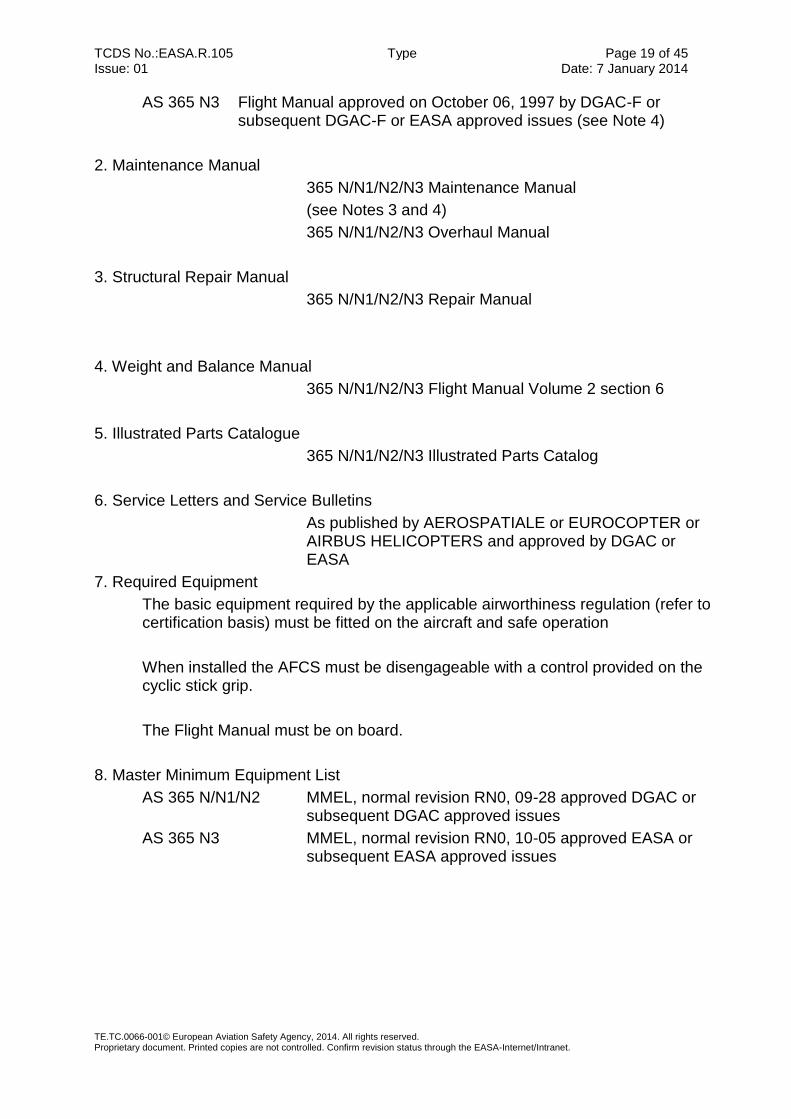
AS 365 N3 Flight Manual approved on October 06, 1997 by DGAC-F or subsequent DGAC-F or EASA approved issues (see Note 4)
2. Maintenance Manual
365 N/N1/N2/N3 Maintenance Manual
(see Notes 3 and 4)
365 N/N1/N2/N3 Overhaul Manual
3. Structural Repair Manual
365 N/N1/N2/N3 Repair Manual
4. Weight and Balance Manual
365 N/N1/N2/N3 Flight Manual Volume 2 section 6
5. Illustrated Parts Catalogue
365 N/N1/N2/N3 Illustrated Parts Catalog
6. Service Letters and Service Bulletins
As published by AEROSPATIALE or EUROCOPTER or AIRBUS HELICOPTERS and approved by DGAC or EASA
7. Required Equipment
The basic equipment required by the applicable airworthiness regulation (refer to certification basis) must be fitted on the aircraft and safe operation
When installed the AFCS must be disengageable with a control provided on the cyclic stick grip.
The Flight Manual must be on board.
8. Master Minimum Equipment List
AS 365 N/N1/N2 MMEL, normal revision RN0, 09-28 approved DGAC or subsequent DGAC approved issues
AS 365 N3 MMEL, normal revision RN0, 10-05 approved EASA or subsequent EASA approved issues

TCDS No.:EASA.R.105 Type Page 20 of 45 Issue: 01 Date: 7 January 2014
TE.TC.0066-001© European Aviation Safety Agency, 2014. All rights reserved. Proprietary document. Printed copies are not controlled. Confirm revision status through the EASA-Internet/Intranet.
V. Notes
1. The weight and C.G. breakdown including the list of equipment items incorporated in the approved empty weight and the loading instruction shall be on board the helicopter at the time when the individual Certificate or Airworthiness is delivered and, then, at any time. To obtain as precise as possible weight and C.G. data, the helicopter shall stay on jacks as fitted at the jacking points rather than on its landing gear. Where modifications are introduced in the helicopter weight and C.G., the Flight Manual instructions shall be referred to.
2. The following placard shall be displayed in clear view of the pilot:
“THIS HELICOPTER MUST BE OPERATED IN COMPLIANCE WITH THE OPERATING LIMITATIONS SPECIFIED IN THE DGAC-APPROVED ROTORCRAFT FLIGHT MANUAL.
THE AIRWORTHINESS LIMITATIONS SECTION OF THE ROTORCRAFT MAINTENANCE MANUAL MUST BE COMPLIED WITH.”
For other placards, refer to Flight Manual
3. Chapters 5 “Master Servicing Recommendations” of the Maintenance Manuals
have been deemed acceptable by the DGAC for maintaining the helicopters satisfactorily. Sub-chapter 5.99 “Airworthiness Limitations” contains the instructions which have to be mandatory complied with.
4. The compatibility between the optional systems is specified :
- in sub-chapter OPTIONAL of the ‘‘Master Servicing Recommendations’’ for installation - in Supplement 0 to Flight Manual for operation
5. This Data Sheet gives the values applicable to the latest 365 designs. For those
aircrafts with a former design or fitted with optional systems or subjected in customization, refer to the Flight Manual for the concerned aircraft.
6. Production conditions: - Production agreement JAR 21 n°F.G.003 granted on December 22, 1997 to EUROCOPTER. - Previous manufacturers: EUROCOPTER FRANCE granted with Production agreement n°P02 starting from January 2, 1992. AEROSPATIALE Division Hélicoptères granted with Production agreement n°P02 starting from November 8, 1991.
7. Commercial designation: DAUPHIN

TCDS No.:EASA.R.105 Type Page 21 of 45 Issue: 01 Date: 7 January 2014
TE.TC.0066-001© European Aviation Safety Agency, 2014. All rights reserved. Proprietary document. Printed copies are not controlled. Confirm revision status through the EASA-Internet/Intranet.
8. Conversion from one version to another one
Original version Version obtained N° of Service Bulletin to be embodied
SA .365 N1 AS .365 N2
AS 365 N3 AS 365 N3
05-00-51 265 01 00 62
9. Certification conditions:
- Design approval n° F.JA.01 granted on July 20, 1998 to EUROCOPTER (formely granted on September 12, 1996 to EUROCOPTER FRANCE)
10. EUROCOPTER document n° L 102-001 contains the list of the serial numbers of the AS 365 N2 and AS 365 N3 manufactured by HELIBRAS

TCDS No.:EASA.R.105 Type Page 22 of 45 Issue: 01 Date: 7 January 2014
TE.TC.0066-001© European Aviation Safety Agency, 2014. All rights reserved. Proprietary document. Printed copies are not controlled. Confirm revision status through the EASA-Internet/Intranet.
SECTION 3: MODEL SA366G1
I. General
1. Type/ Model/ Variant
1.1 Type
SA366
1.2 Model
SA366G1
1.3 Variant
N/A
2. Airworthiness Category
Large Rotorcraft, Category A and B
3. Manufacturer
before January 1, 1992 AEROSPATIALE
before January 7, 2014 EUROCOPTER
since January 7, 2014 AIRBUS HELICOPTERS
Aéroport International Marseille-Provence
13725 MARIGNANE cedex
4. EASA Certification Application Date Note: State of Design Authority certification application date for grandfathered products
SA 366 G1 02 August 1982
5. State of Design
DGAC-FRANCE
6. State of Design Authority Type Certification Date
SA 366 G1 09 May 1983
7. EASA Type Certification Date N/A
II. Certification Basis
1. Reference Date for determining the applicable requirements
September 26, 1980
2. Airworthiness Requirements
FAR Part 29 Amendments 1 through 16

TCDS No.:EASA.R.105 Type Page 23 of 45 Issue: 01 Date: 7 January 2014
TE.TC.0066-001© European Aviation Safety Agency, 2014. All rights reserved. Proprietary document. Printed copies are not controlled. Confirm revision status through the EASA-Internet/Intranet.
3. Special Conditions
Complementary and special conditions defined in DGAC letter 54022 dated September 26, 1980
The “Plenum” air intake associated with engine LYCOMING LTS 101.750 B2 meets the ice protection requirements laid down in paragraph 29.1309(b)(2), amendment 22
4. Exemptions
None.
5. (Reserved) Deviations
None.
6. Equivalent Safety Findings
None
7. Environmental Protection Requirements
None
III. Technical Characteristics and Operational Limitations
1. Type Design Definition
SA 366 G1 basic SA 366 G1 definition document 365A04 3017
2. Description
Large twin-engine helicopter
3. Equipment
N/A
4. Dimensions
4.1 Fuselage Width 3.40 m (11.15 ft)
Height 3.21 m (10.53 ft)
Length 11.44 m (37.53 ft)
4.2 Main Rotor Diameter 11.93 m (39.14 ft)
4.3 Tail Rotor Diameter 0.90 m (2.95 ft)

TCDS No.:EASA.R.105 Type Page 24 of 45 Issue: 01 Date: 7 January 2014
TE.TC.0066-001© European Aviation Safety Agency, 2014. All rights reserved. Proprietary document. Printed copies are not controlled. Confirm revision status through the EASA-Internet/Intranet.
5. Engine
5.1 Model
2 LYCOMING LTS 101.750 B2 turboshaft engines
The installation of this engine is associated to the “Plenum” air intake
5.2 Type Certificate
See engine TCDS IM.E.228
5.3 Limitations
5.3.1 Installed Engine Limits
refer to approved Flight Manual
5.3.2 Transmission Torque Limits
refer to approved Flight Manual
6. Fluids (Fuel/ Oil/ Additives)
6.1 Fuel
as approved in the Flight Manual
6.2 Oil
as approved in the Flight Manual
6.3 Additives
as approved in the Flight Manual
7. Fluid capacities
7.1 Fuel
Usable 1075 l (284 US gals)
Unusable + 22 l (6 US gals)
Total 1097 l (290 US gals)
7.2 Oil
Power plant 2 x .4 l (normal level)
MGB 9 l (max. level)
TGB 0.2 l (max. level)

TCDS No.:EASA.R.105 Type Page 25 of 45 Issue: 01 Date: 7 January 2014
TE.TC.0066-001© European Aviation Safety Agency, 2014. All rights reserved. Proprietary document. Printed copies are not controlled. Confirm revision status through the EASA-Internet/Intranet.
7.3 Coolant system capacity
RH system: 5.5 l
LH system: 8 l
8. Air Speeds Limits
Vne Power on 306 km/h (165 kt) at 0 m for M < 3000 kg (6.614lb)
Then decreasing as a function of altitude and weight
(See Flight Manual)
Vne Power off 250 km/h (135 kt) at 0 m
Then decreasing as a function of altitude and weight
(See Flight Manual)
9. Rotor Speed Limits
Power on Governed speed 350 +8-10 rpm
Transient 320 rpm
Power off Max. transient 420 rpm
Maximum 395 (aural alarm at 380 rpm)
Minimum 320 rpm (aural alarm at 335 rpm)
Min transient 295 rpm
10. Maximum Operating Altitude and Temperature
9.1 Altitude
18 000 ft (5486 m)
9.2 Temperature
-25°C to +50°C
11. Operating Limitations
as approved in the Flight Manual
12. Maximum Weight
SA 366 G1 4060kg (8951lb)
13. Centre of Gravity Range
Longitudinal Forward limit 3.84 m
Rear limit 4.00 m
Lateral R.H. 0.143 m
L.H. 0.100 m

TCDS No.:EASA.R.105 Type Page 26 of 45 Issue: 01 Date: 7 January 2014
TE.TC.0066-001© European Aviation Safety Agency, 2014. All rights reserved. Proprietary document. Printed copies are not controlled. Confirm revision status through the EASA-Internet/Intranet.
14. Datum
Longitudinal 4 m (13 ft) main rotor centreline
Lateral aircraft symmetry plane
15. Levelling Means
Three levelling blocks on transmission deck
16. Minimum Flight Crew
1 pilot on RH seat
17. Maximum Passenger Seating Capacity
2
18. Passenger Emergency Exit
Refer to approved Flight Manual
19. Maximum Baggage/ Cargo Loads
Cargo transport prohibited
20. Rotor Blade control movement
For rigging information, refer to Maintenance Manual
21. APU
N/A
22. Life- limited parts
Refer to approved ALS chapter of the MSM
23. Wheels and Tyres
Main Landing gear
Wheel ERAM 20475
Tyre Dunlop 380*150.6, tyre pressure 8.5 bars
Auxiliary landing gear E18740
Wheel ERAM 18755
Tyres Dunlop 330*130 , tyre pressure 5.5 bars
TCDS No.:EASA.R.105 Type Page 27 of 45 Issue: 01 Date: 7 January 2014
TE.TC.0066-001© European Aviation Safety Agency, 2014. All rights reserved. Proprietary document. Printed copies are not controlled. Confirm revision status through the EASA-Internet/Intranet.
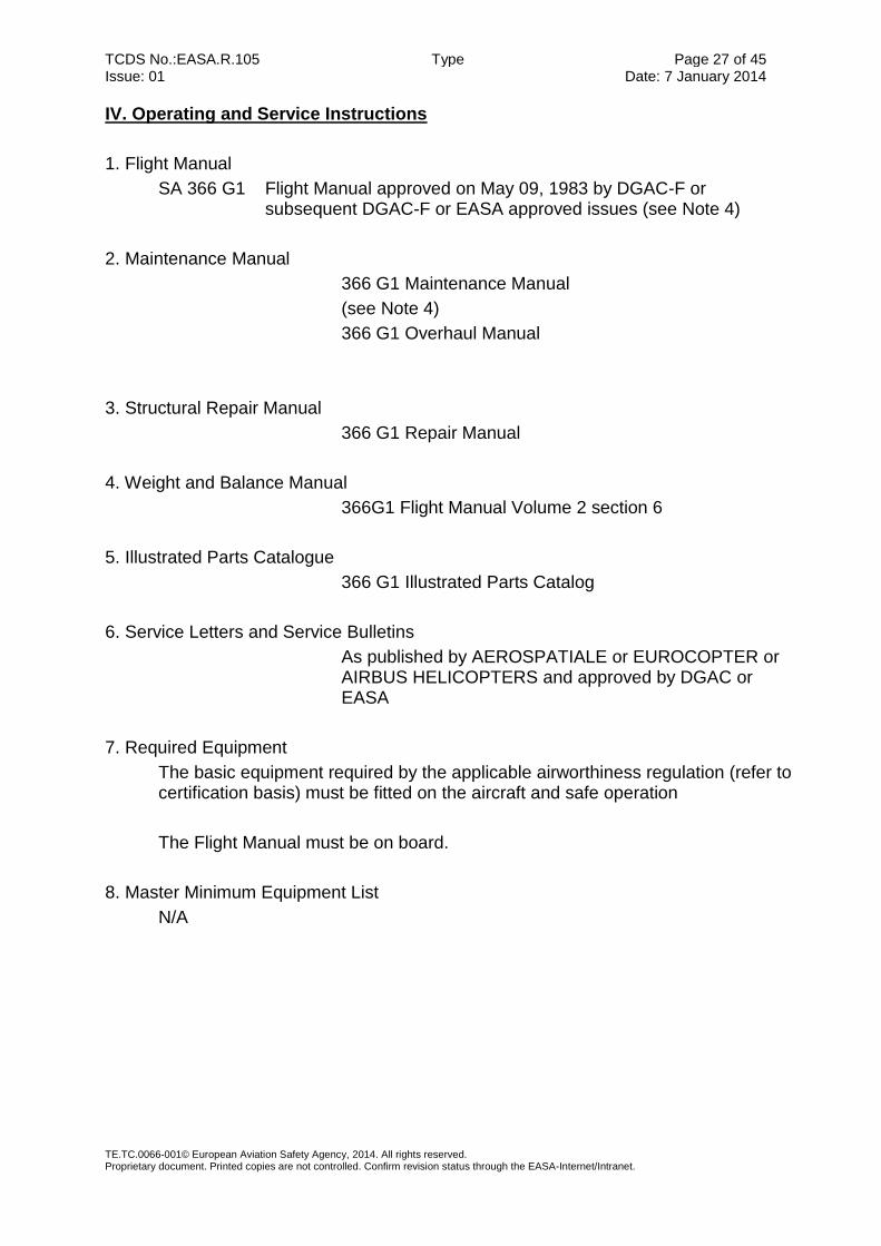
IV. Operating and Service Instructions
1. Flight Manual
SA 366 G1 Flight Manual approved on May 09, 1983 by DGAC-F or subsequent DGAC-F or EASA approved issues (see Note 4)
2. Maintenance Manual
366 G1 Maintenance Manual
(see Note 4)
366 G1 Overhaul Manual
3. Structural Repair Manual
366 G1 Repair Manual
4. Weight and Balance Manual
366G1 Flight Manual Volume 2 section 6
5. Illustrated Parts Catalogue
366 G1 Illustrated Parts Catalog
6. Service Letters and Service Bulletins
As published by AEROSPATIALE or EUROCOPTER or AIRBUS HELICOPTERS and approved by DGAC or EASA
7. Required Equipment
The basic equipment required by the applicable airworthiness regulation (refer to certification basis) must be fitted on the aircraft and safe operation
The Flight Manual must be on board.
8. Master Minimum Equipment List
N/A

TCDS No.:EASA.R.105 Type Page 28 of 45 Issue: 01 Date: 7 January 2014
TE.TC.0066-001© European Aviation Safety Agency, 2014. All rights reserved. Proprietary document. Printed copies are not controlled. Confirm revision status through the EASA-Internet/Intranet.
V. Notes
1. The weight and C.G. breakdown including the list of equipment items
incorporated in the approved empty weight and the loading instruction shall be on board the helicopter at the time when the individual Certificate or Airworthiness is delivered and, then, at any time. To obtain as precise as possible weight and C.G. data, the helicopter shall stay on jacks as fitted at the jacking points rather than on its landing gear. Where modifications are introduced in the helicopter weight and C.G., the Flight Manual instructions shall be referred to.
2. The following placard shall be displayed in clear view of the pilot:
“THIS HELICOPTER MUST BE OPERATED IN COMPLIANCE WITH THE OPERATING LIMITATIONS SPECIFIED IN THE DGAC-APPROVED ROTORCRAFT FLIGHT MANUAL. THE AIRWORTHINESS LIMITATIONS SECTION OF THE ROTORCRAFT MAINTENANCE MANUAL MUST BE COMPLIED WITH.” For other placards, refer to Flight Manual
3. Chapters 5 “Master Servicing Recommendations” of the Maintenance Manuals
have been deemed acceptable by the DGAC for maintaining the helicopters satisfactorily. Sub-chapter 5.99 “Airworthiness Limitations” contains the instructions which have to be mandatory complied with.
4. The compatibility between the optional systems is specified :
- in sub-chapter OPTIONAL of the ‘‘Master Servicing Recommendations’’ for installation - in Supplement 0 to Flight Manual for operation
5. This Data Sheet gives the values applicable to the latest 365 and 366 designs. For those aircrafts with a former design or fitted with optional systems or subjected in customization, refer to the Flight Manual for operation.
6. Production conditions: - Production agreement JAR 21 n°F.G.003 granted on December 22, 1997 to EUROCOPTER. - Previous manufacturers: EUROCOPTER FRANCE granted with Production agreement n°P02 starting from January 2, 1992. AEROSPATIALE Division Hélicoptères granted with Production agreement n°P02 starting from November 8, 1991.
7. Commercial designation: DAUPHIN
8. Certification conditions:
- Design approval n° F.JA.01 granted on July 20, 1998 to EUROCOPTER (formerly granted on September 12, 1996 to EUROCOPTER FRANCE)

TCDS No.:EASA.R.105 Type Page 29 of 45 Issue: 01 Date: 7 January 2014
TE.TC.0066-001© European Aviation Safety Agency, 2014. All rights reserved. Proprietary document. Printed copies are not controlled. Confirm revision status through the EASA-Internet/Intranet.
SECTION 4: MODEL EC155 B
I. General
1. Type/ Model/ Variant
1.1 Type
EC155
1.2 Model
EC155B
1.3 Variant
N/A
2. Airworthiness Category
Large Rotorcraft, Category A and B
3. Manufacturer
before January 7, 2014 EUROCOPTER
since January 7, 2014 AIRBUS HELICOPTERS
Aéroport International Marseille-Provence
13725 MARIGNANE cedex
4. EASA Certification Application Date Note: State of Design Authority certification application date for grandfathered products
20 November 1997
5. State of Design
DGAC-FRANCE
6. State of Design Authority Type Certification Date
09 December 1998
7. EASA Type Certification Date N/A
II. Certification Basis
1. Reference Date for determining the applicable requirements
20 November 1997

TCDS No.:EASA.R.105 Type Page 30 of 45 Issue: 01 Date: 7 January 2014
TE.TC.0066-001© European Aviation Safety Agency, 2014. All rights reserved. Proprietary document. Printed copies are not controlled. Confirm revision status through the EASA-Internet/Intranet.
2. Airworthiness Requirements
JAR 29, first issue effective November 5, 1993.
According to DGAC letter 986771 SFACT/N.HE dated December 02, 1998, completed by DGAC letter SFACT/N.HE.-2003/0314 dated January 31, 2003.
3. Special Conditions
HIRF (High Intensity Radiated Fields) (reference CRI F-01)
Minimum In Flight Experience (Reference CRI B-01)
Ingestion of Hail (Reference CRI C-05)
4. Exemptions
•Reversions to FAR 29:
- FAR 29.561(b)(3) at amendment 29-16 Emergency Landing Conditions – General (Reference CRI –C01)
- FAR 29.571 at amendment 29-16 (for metallic fuselage and mechanical components issued from previous AS365 models only) Fatigue Evaluation of Structure (Reference CRI C-06)
-FAR 29.785 at amendment 29-24 Seat, Safety belts and Harness (Reference CRI D-03)
- FAR 29.1305(a)(4)(i) at amendment 29-16 Low Fuel Warning (Reference CRI F-02)
•Exemption from JAR 29 first issue:
- JAR 29.562 Emergency dynamic Landing Conditions (Reference CRI C-02)
- JAR 631 Bird Strike (for optional installations taken from previous AS365 versions and to a certain extent for windshield) (Reference CRI C-03)
- JAR 29.952 Fuel System Crash Resistance (Reference CRI E-01)
5. (Reserved) Deviations
None
6. Equivalent Safety Findings
- JAR 29.173-175 Static Longitudinal Stability (Reference CRI B-02)
- JAR 29.807(c) Passenger Emergency Exits (Reference CRI D-05)
- JAR 29.923(p)(1) Rotor Drive endurance Test for Tail Gear Box (Reference CRI E-04)
- JAR 29.955(b) Fuel Transfer System (Reference CRI E-05)
- JAR 29.1151 Rotor Brake Indication (Reference CRI E-03)
- JAR 29.1303(j) VNE Aural Warning (Reference CRI F-05)
- JAR 29.1401(d) Red Anti-collision Light (Reference CRI EC155B F-09)
- JAR 29.1545(b)(4) Airspeed Indicator Marking (Reference CRI F-07)
- JAR 29.1549(b) Power plant Instrument Marking (Reference CRI F-06)

TCDS No.:EASA.R.105 Type Page 31 of 45 Issue: 01 Date: 7 January 2014
TE.TC.0066-001© European Aviation Safety Agency, 2014. All rights reserved. Proprietary document. Printed copies are not controlled. Confirm revision status through the EASA-Internet/Intranet.
- JAR 29 Appendix B § IV for Speed Stability (Reference CRI B-03)
7. Environmental Protection Requirements
Noise
French “Arrêté” of February 19, 1987
Fuel Discharge
ICAO recommendations for discharging fuel annexe 16, volume 2, 2nd
III. Technical Characteristics and Operational Limitations
1. Type Design Definition
According to EUROCOPTER document 365A04.6060
2. Description
According to EUROCOPTER document 365A04.6000
3. Equipment
According to EUROCOPTER document 365A04.6422
4. Dimensions
4.1 Fuselage Width 3.48 m (11.42 ft)
Height 4.35 m (14.27 ft)
Length 12.71 m (41.70 ft)
4.2 Main Rotor Diameter 12.60 m (41.34 ft)
4.3 Tail Rotor Diameter 1.10 m (3.61 ft)
5. Engine
5.1 Model
2 TURBOMECA – ARRIEL 2C1 turboshaft engines
5.2 Type Certificate
See engine TCDS E.001
5.3 Limitations
5.3.1 Installed Engine Limits
refer to approved Flight Manual
5.3.2 Transmission Torque Limits
refer to approved Flight Manual

TCDS No.:EASA.R.105 Type Page 32 of 45 Issue: 01 Date: 7 January 2014
TE.TC.0066-001© European Aviation Safety Agency, 2014. All rights reserved. Proprietary document. Printed copies are not controlled. Confirm revision status through the EASA-Internet/Intranet.
6. Fluids (Fuel/ Oil/ Additives)
6.1 Fuel
as approved in the Flight Manual
6.2 Oil
as approved in the Flight Manual
6.3 Additives
as approved in the Flight Manual
7. Fluid capacities
7.1 Fuel
Usable 1256,5 l (332 US gals)
Unusable + 23,5 l (4 US gals)
Total 1280 l (336 US gals)
7.2 Oil
Power plant 2 x .6,2 l (normal level)
MGB 9 l (max. level)
TGB 0.5 l (max. level)
7.3 Coolant system capacity
RH system: 5.5 l
LH system: 6.5 l
8. Air Speeds Limits
Vne Power on 324 km/h (175 kt)
Decrease function of altitude: Refer to Flight Manual
Vne Power off 250 km/h (135 kt) at 0 m
Decrease function of altitude: Refer to Flight Manual
9. Rotor Speed Limits
Power on Governed speed 342 to 350 rpm
Power off Max. transient 390 rpm
Maximum 375 rpm
Minimum 316 rpm
Min transient 295 rpm

TCDS No.:EASA.R.105 Type Page 33 of 45 Issue: 01 Date: 7 January 2014
TE.TC.0066-001© European Aviation Safety Agency, 2014. All rights reserved. Proprietary document. Printed copies are not controlled. Confirm revision status through the EASA-Internet/Intranet.
10. Maximum Operating Altitude and Temperature
10.1 Altitude
Flight Hp = 3965 m (13000 ft)
Take-off and landing Hp = 2591 m (8500 ft)
10.2 Temperature
-15°C < OAT < +40°C -40°C < OAT < +40°C providing the installation of EUROCOPTER modification n° 62C17, 67B62, 39C30, 39C37, 22B55, 29B62, 29B64 and 11B62
11. Operating Limitations
Day/night VFR, IFR, Category B, Category A (see Note 5)
12. Maximum Weight
4800 kg (10582 lb)
13. Centre of Gravity Range
Longitudinal Forward limit 3.80 m
Rear limit 4.07 m
Lateral R.H. 0.05 m
L.H. 0.05 m
14. Datum
Longitudinal 4 m forward of main rotor centreline
Lateral aircraft symmetry plane
15. Levelling Means
Three levelling blocks on transmission deck
16. Minimum Flight Crew
1 pilot on RH seat
17. Maximum Passenger Seating Capacity
15 (including pilot seats)
18. Passenger Emergency Exit
Refer to approved Flight Manual
19. Maximum Baggage/ Cargo Loads
Maximum load 300 kg
Distributed maximum load 295 kg/m²

TCDS No.:EASA.R.105 Type Page 34 of 45 Issue: 01 Date: 7 January 2014
TE.TC.0066-001© European Aviation Safety Agency, 2014. All rights reserved. Proprietary document. Printed copies are not controlled. Confirm revision status through the EASA-Internet/Intranet.
20. Rotor Blade control movement
For rigging information, refer to Maintenance Manual
21. APU
N/A
22. Life- limited parts
Refer to approved ALS chapter of the MSM
23. Wheels and Tyres
Main Landing gear
Wheel ERAM 20475
Tyre Dunlop UK or GOODYEAR 380*150.6, tyre pressure 8.5 bars
Auxiliary landing gear
Wheel ERAM 18755
Tyres Dunlop UK or GOODYEAR 330*130 , tyre pressure 5.5 bars
IV. Operating and Service Instructions
1. Flight Manual
EC155B Flight Manual, normal revision RN0, 98-37 approved by DGAC on December 4, 1998 or subsequent DGAC or EASA approved issues
2. Maintenance Manual
EC155B Master Servicing Manual Chapter 04 “Airworthiness Limitations” approved on December 09, 1998 or later DGAC or EASA approved revisions.
EC155B Aircraft Maintenance Manual
3. Structural Repair Manual
EC155B Structural Repair Manual
4. Weight and Balance Manual
EC155B Flight Manual Volume 2 section 6
5. Illustrated Parts Catalogue
EC155B Illustrated Parts Catalog

TCDS No.:EASA.R.105 Type Page 35 of 45 Issue: 01 Date: 7 January 2014
TE.TC.0066-001© European Aviation Safety Agency, 2014. All rights reserved. Proprietary document. Printed copies are not controlled. Confirm revision status through the EASA-Internet/Intranet.
6. Service Letters and Service Bulletins
As published by EUROCOPTER or AIRBUS HELICOPTERS and approved by DGAC or EASA
7. Required Equipment
The basic equipment required by the applicable airworthiness regulation (refer to certification basis) must be fitted on the aircraft and safe operation
The Flight Manual must be on board.
8. Master Minimum Equipment List
EC155B MMEL, normal revision RN0, 09-43 approved by EASA or subsequent EASA approved issues

TCDS No.:EASA.R.105 Type Page 36 of 45 Issue: 01 Date: 7 January 2014
TE.TC.0066-001© European Aviation Safety Agency, 2014. All rights reserved. Proprietary document. Printed copies are not controlled. Confirm revision status through the EASA-Internet/Intranet.
V. Notes
1. The weight and C.G. breakdown including the list of equipment items
incorporated in the approved empty weight and the loading instruction shall be on board the helicopter at the time when the individual Certificate or Airworthiness is delivered and, then, at any time. To obtain as precise as possible weight and C.G. data, the helicopter shall stay on jacks as fitted at the jacking points rather than on its landing gear. Where modifications are introduced in the helicopter weight and C.G., the Flight Manual instructions shall be referred to.
2. The EC155B Master Servicing Manual has been deemed acceptable by the DGAC to perform proper maintenance on the helicopters. EC155B MSM Chapter 04 “Airworthiness Limitations” covers the instructions that must be complied with.
3. Production conditions:
- Production agreement JAR 21 n°F.G.003 granted on December 22, 1997 to EUROCOPTER.
4. Certification conditions:
- Design approval n° F.JA.01 granted on July 20, 1998 to EUROCOPTER (formerly granted on September 12, 1996 to EUROCOPTER FRANCE)
5. Category A operations require the following modification to be embodied: AMS N° 07-22B47 Single pilot IFR Flights require the following modifications to be embodied: AMS N° 07-39B78, 07-39B79, 07-71B85 and 07-71B91
6. Eligible serial numbers: 6544 and subsequent of EC 155 B version.

TCDS No.:EASA.R.105 Type Page 37 of 45 Issue: 01 Date: 7 January 2014
TE.TC.0066-001© European Aviation Safety Agency, 2014. All rights reserved. Proprietary document. Printed copies are not controlled. Confirm revision status through the EASA-Internet/Intranet.
SECTION 5: MODEL EC155 B1
I. General
1. Type/ Model/ Variant
1.1 Type
EC155
1.2 Model
EC155B1
1.3 Variant
N/A
2. Airworthiness Category
Large Rotorcraft, Category A and B
3. Manufacturer
before January 7, 2014 EUROCOPTER
since January 7, 2014 AIRBUS HELICOPTERS
Aéroport International Marseille-Provence
13725 MARIGNANE cedex
4. EASA Certification Application Date Note: State of Design Authority certification application date for grandfathered products
07 February 2001
5. State of Design
DGAC-FRANCE
6. State of Design Authority Type Certification Date
16 July 2002
7. EASA Type Certification Date N/A
II. Certification Basis
1. Reference Date for determining the applicable requirements
20 November 1997

TCDS No.:EASA.R.105 Type Page 38 of 45 Issue: 01 Date: 7 January 2014
TE.TC.0066-001© European Aviation Safety Agency, 2014. All rights reserved. Proprietary document. Printed copies are not controlled. Confirm revision status through the EASA-Internet/Intranet.
2. Airworthiness Requirements
JAR 29, first issue effective November 5, 1993
According to DGAC letter 2002/053/SFACT/N.HE dated February 07, 2002, completed by DGAC letter SFACT/N.HE.-2003/0315 dated February 03, 2003
3. Special Conditions
HIRF (High Intensity Radiated Fields) (reference CRI EC155B F-01)
Minimum In Flight Experience (Reference CRI EC155B1 B-01)
Ingestion of Hail (Reference CRI EC155B C-05)
4. Exemptions
• Reversions to FAR 29:
- FAR 29.561(b)(3) at amendment 29-16 Emergency Landing Conditions – General (Reference CRI EC155B –C01)
- FAR 29.571 at amendment 29-16 (for metallic fuselage and mechanical components issued from previous AS365 models only) Fatigue Evaluation of Structure (Reference CRI EC155B C-06)
-FAR 29.785 at amendment 29-24 Seat, Safety belts and Harness (Reference CRI EC155B D-03)
- FAR 29.1305(a)(4)(i) at amendment 29-16 Low Fuel Warning (Reference CRI EC155B F-02)
•Exemption from JAR 29 first issue:
- JAR 29.562 Emergency dynamic Landing Conditions (Reference CRI EC155B C-02)
- JAR 631 Bird Strike (for optional installations taken from previous AS365 versions and to a certain extent for windshield) (Reference CRI EC155B C-03)
- JAR 29.952 Fuel System Crash Resistance (Reference CRI EC155B E-01)
5. (Reserved) Deviations
None
6. Equivalent Safety Findings
- JAR 29.173-175 Static Longitudinal Stability (Reference CRI EC155B B-02)
- JAR 29.807(c) Passenger Emergency Exits (Reference CRI EC155B D-05)
- JAR 29.923(p)(1) Rotor Drive endurance Test (Reference CRI EC155B1 E-04)
- JAR 29.923 and JAR 29.927(b)(2) Rotor Drive System and Control Mechanism Tests and Additional Tests (Reference CRI EC155B1 E-01)
- JAR 29.955(b) Fuel Transfer System (Reference CRI EC155B1 E-02)
- JAR 29.1151 Rotor Brake Indication (Reference CRI EC155B E-03)
- JAR 29.1303(j) VNE Aural Warning (Reference CRI EC155B F-05)
- JAR 29.1401(d) Red Anticollision Light (Reference CRI F-09)

TCDS No.:EASA.R.105 Type Page 39 of 45 Issue: 01 Date: 7 January 2014
TE.TC.0066-001© European Aviation Safety Agency, 2014. All rights reserved. Proprietary document. Printed copies are not controlled. Confirm revision status through the EASA-Internet/Intranet.
- JAR 29.1545(b)(4) Airspeed Indicator Marking (Reference CRI EC155B F-07)
- JAR 29.1549(b) Power plant Instrument Marking (Reference CRI EC155B F-06)
- JAR 29 Appendix B § IV for Speed Stability (Reference CRI EC155B B-03)
7. Environmental Protection Requirements
Noise
French “Arrêté” of February 19, 1987
Fuel Discharge
ICAO recommendations for discharging fuel annexe 16, volume 2, 2nd
III. Technical Characteristics and Operational Limitations
1. Type Design Definition
According to EUROCOPTER document 365A04.6926
2. Description
According to EUROCOPTER document 365A04.6840
3. Equipment
According to EUROCOPTER document 365A04.6422
4. Dimensions
4.1 Fuselage Width 3.48 m (11.42 ft)
Height 4.35 m (14.27 ft)
Length 12.71 m (41.70 ft)
4.2 Main Rotor Diameter 12.60 m (41.34 ft)
4.3 Tail Rotor Diameter 1.10 m (3.61 ft)
5. Engine
5.1 Model
2 TURBOMECA – ARRIEL 2C2 turboshaft engines
5.2 Type Certificate
See engine TCDS E.001
5.3 Limitations
5.3.1 Installed Engine Limits
refer to approved Flight Manual
5.3.2 Transmission Torque Limits

TCDS No.:EASA.R.105 Type Page 40 of 45 Issue: 01 Date: 7 January 2014
TE.TC.0066-001© European Aviation Safety Agency, 2014. All rights reserved. Proprietary document. Printed copies are not controlled. Confirm revision status through the EASA-Internet/Intranet.
refer to approved Flight Manual
6. Fluids (Fuel/ Oil/ Additives)
6.1 Fuel
as approved in the Flight Manual
6.2 Oil
as approved in the Flight Manual
6.3 Additives
as approved in the Flight Manual
7. Fluid capacities
7.1 Fuel
Usable 1256,5 l (332 US gals)
Unusable + 23,5 l (4 US gals)
Total 1280 l (336 US gals)
7.2 Oil
Power plant 2 x .6,2 l (normal level)
MGB 9 l (max. level)
TGB 0.5 l (max. level)
7.3 Coolant system capacity
RH system: 5.5 l
LH system: 6.5 l
8. Air Speeds Limits
Vne Power on 324 km/h (175 kt)
Decrease function of altitude: Refer to Flight Manual
Vne Power off 250 km/h (135 kt) at 0 m
Decrease function of altitude: Refer to Flight Manual
9. Rotor Speed Limits
Power on Governed speed 342 to 350 rpm
Power off Max. transient 390 rpm
Max steady state 375 rpm
Minimum 316 rpm
Min transient 295 rpm

TCDS No.:EASA.R.105 Type Page 41 of 45 Issue: 01 Date: 7 January 2014
TE.TC.0066-001© European Aviation Safety Agency, 2014. All rights reserved. Proprietary document. Printed copies are not controlled. Confirm revision status through the EASA-Internet/Intranet.
10. Maximum Operating Altitude and Temperature
9.1 Altitude
Flight Hp = 4572 m (15000 ft)
Take-off and landing Hp = 3960 m (13000 ft)
9.2 Temperature
-15°C < OAT < +40°C - 40°C < OAT < +40°C providing the installation of EUROCOPTER modification n° 62C17, 67B62, 39C30, 39C37, 22B55, 29B62, 29B64 and 11B62
11. Operating Limitations
Day/night VFR, IFR, Category B, Category A
12. Maximum Weight
General 4850 kg (10692 lb) or 4920 kg (10913 lb) for helicopters equipped with EUROCOPTER modifications n° 62C17, 67B62, 39C30, 39C37, 22B55, 29B62, 29B64 and 11B62 and limited to operations at -30°C < OAT < +50°C
Taxiing 4950 kg (10913 lb)
13. Centre of Gravity Range
Longitudinal Forward limit 3.80 m
Rear limit 4.07 m
Lateral R.H. 0.05 m
L.H. 0.05 m
14. Datum
Longitudinal 4 m forward of main rotor centreline
Lateral aircraft symmetry plane
15. Levelling Means
Three levelling blocks on transmission deck
16. Minimum Flight Crew
1 pilot on RH seat
17. Maximum Passenger Seating Capacity
15 (including pilot seats)

TCDS No.:EASA.R.105 Type Page 42 of 45 Issue: 01 Date: 7 January 2014
TE.TC.0066-001© European Aviation Safety Agency, 2014. All rights reserved. Proprietary document. Printed copies are not controlled. Confirm revision status through the EASA-Internet/Intranet.
18. Passenger Emergency Exit
Refer to approved Flight Manual
19. Maximum Baggage/ Cargo Loads
Maximum load 300 kg
Distributed maximum load 295 kg/m²
20. Rotor Blade control movement
For rigging information, refer to Maintenance Manual
21. APU
N/A
22. Life- limited parts
Refer to approved ALS chapter of the MSM
23. Wheels and Tyres
Main Landing gear
Wheel ERAM 20475
Tyre Dunlop UK or GOODYEAR 380*150.6, tyre pressure 8.5 bars
Auxiliary landing gear E18740
Wheel ERAM 18755
Tyres Dunlop UK or GOODYEAR 330*130 , tyre pressure 5.5 bars
IV. Operating and Service Instructions
1. Flight Manual
EC155B Flight Manual, normal revision RN0, 02-20 approved by DGAC on July 31, 2002 or subsequent DGAC or EASA approved issues
2. Maintenance Manual
EC155B1 Master Servicing Manual Chapter 04 “Airworthiness Limitations” approved on July 31, 2002 or later DGAC or EASA approved revisions.
EC155B1 Aircraft Maintenance Manual
3. Structural Repair Manual
EC155B1 Structural Repair Manual

TCDS No.:EASA.R.105 Type Page 43 of 45 Issue: 01 Date: 7 January 2014
TE.TC.0066-001© European Aviation Safety Agency, 2014. All rights reserved. Proprietary document. Printed copies are not controlled. Confirm revision status through the EASA-Internet/Intranet.
4. Weight and Balance Manual
EC155B1 Flight Manual Volume 2 section 6
5. Illustrated Parts Catalogue
EC155B1 Illustrated Parts Catalog
6. Service Letters and Service Bulletins
As published by EUROCOPTER or AIRBUS HELICOPTERS and approved by DGAC or EASA
7. Required Equipment
The basic equipment required by the applicable airworthiness regulation (refer to certification basis) must be fitted on the aircraft and safe operation.
The Flight Manual must be on board.
8. Master Minimum Equipment List
EC155B1 MMEL, normal revision RN0, 09-43 approved by EASA or subsequent EASA approved issues.

TCDS No.:EASA.R.105 Type Page 44 of 45 Issue: 01 Date: 7 January 2014
TE.TC.0066-001© European Aviation Safety Agency, 2014. All rights reserved. Proprietary document. Printed copies are not controlled. Confirm revision status through the EASA-Internet/Intranet.
V. Notes
1. The weight and C.G. breakdown including the list of equipment items
incorporated in the approved empty weight and the loading instruction shall be on board the helicopter at the time when the individual Certificate or Airworthiness is delivered and, then, at any time. To obtain as precise as possible weight and C.G. data, the helicopter shall stay on jacks as fitted at the jacking points rather than on its landing gear. Where modifications are introduced in the helicopter weight and C.G., the Flight Manual instructions shall be referred to.
2. The EC155B1 Master Servicing Manual has been deemed acceptable by the DGAC to perform proper maintenance on the helicopters. EC155B1 MSM Chapter 04 “Airworthiness Limitations” covers the instructions that must be complied with.
3. Production conditions:
- Production agreement JAR 21 n°F.G.003 granted on December 22, 1997 to EUROCOPTER.
4. Certification conditions:
- Design approval n° F.JA.01 granted on July 20, 1998 to EUROCOPTER (formerly granted on September 12, 1996 to EUROCOPTER FRANCE)
5. Eligible serial numbers: 6620 and subsequent of EC 155 B1 version.
TCDS No.:EASA.R.105 Type Page 45 of 45 Issue: 01 Date: 7 January 2014
TE.TC.0066-001© European Aviation Safety Agency, 2014. All rights reserved. Proprietary document. Printed copies are not controlled. Confirm revision status through the EASA-Internet/Intranet.
SECTION 6: ADMINISTRATIVE
I. Acronyms and Abbreviations
ALS Airworthiness Limitations Section DOA Design Organisation Approval EASA European Aviation Safety Agency FAA Federal Aviation Administration HIRF High Intensity Radiated Field ICAO International Civil Aviation Organisation IPC Illustrated Parts Catalogue JAA Joint Aviation Authorities JAR Joint Airworthiness Requirements kg Kilogram lb. Pounds MMEL Master Minimum Equipment List MSM Maintenance Servicing Manual RFM Rotorcraft Flight Manual
II. Type Certificate Holder Record
AIRBUS HELICOPTERS Aeroport International Marseille-Provence 13725 MARIGNANE cedex - France
III. Change Record
Issue Date Changes TC issue
Issue 01 07/01/2014 Initial issue on EASA TCDS format Previous was DGAC TCDS N°159 ed 21 dated February 2005 Minor corrections
Initial Issue, 07/01/2014
-END-