
EUROPA GLIDER WING SPAR REINFORCEMENT Bulletin No 78 Issue 2.pdf · EUROPA GLIDER WING SPAR...
14
Mod 78 - Europa MG Wing Spar Tang Reinforcement Mod 78 Issue 2 Page 1 of 14 March 2011 _______________________________________________ EUROPA GLIDER WING SPAR REINFORCEMENT 1. Classification: Mandatory 2. Applicability: Europa Motor Gliders Note: Issue 2 of Mod 78 applies to those Europa Motorgliders that do not require the approval of the UK LAA for the Permit to Fly (or national equivalents) 3. Compliance: Within the next 25 flying hours 4. Introduction: The latest glider wing/fuselage combined structural test carried out by the Europa Aircraft (2004) Ltd has highlighted the requirement for additional reinforcement on both the port and starboard glider wing spars originally designed by Europa Aircraft Ltd. The reinforcement consists of additional carbon ropes wrapped around the existing spar to increase the spar depth at the wing root. The number of shear web carbon cloth layers is also increased to 8 layers on both sides of the tang. This modification does not affect XS or Classic standard wings. NOTE: THIS REPAIR INVOLVES WORKING ON THE PRIMARY WING STRUCTURE OF THE AIRCRAFT AND MUST ONLY BE ATTEMPTED BY PERSONNEL EXPERIENCED IN THE USE OF COMPOSITE TECHNIQUES AND MATERIALS. IF THE BUILDER DOES NOT FEEL CAPABLE OF CARRYING OUT THIS WORK THEN HE SHOULD CONTACT THE FACTORY OR ITS DEALER NETWORK FOR ADVICE. THE WHOLE OF THIS DOCUMENT SHOULD BE READ IN ITS ENTIRETY BEFORE COMMENCING WITH THE WORK. IF IN DOUBT, YOU MUST CONSULT EUROPA AIRCRAFT FOR CLARIFICATION. 5. Actions: 5.1: Mould Tool Preparation: As the glider wing spar bush positions are back drilled from the Europa fuselage a moulding jig will be required to ensure the bushes are replaced in
Transcript of EUROPA GLIDER WING SPAR REINFORCEMENT Bulletin No 78 Issue 2.pdf · EUROPA GLIDER WING SPAR...
Mod 78 - Europa MG Wing Spar Tang Reinforcement
Mod 78 Issue 2 Page 1 of 14 March 2011
_______________________________________________
EUROPA GLIDER WING SPAR REINFORCEMENT
1. Classification: Mandatory 2. Applicability: Europa Motor Gliders
Note: Issue 2 of Mod 78 applies to those Europa Motorgliders that do not require the approval of the UK LAA for the Permit to Fly (or national equivalents)
3. Compliance: Within the next 25 flying hours 4. Introduction: The latest glider wing/fuselage combined structural test carried out by the Europa Aircraft (2004) Ltd has highlighted the requirement for additional reinforcement on both the port and starboard glider wing spars originally designed by Europa Aircraft Ltd. The reinforcement consists of additional carbon ropes wrapped around the existing spar to increase the spar depth at the wing root. The number of shear web carbon cloth layers is also increased to 8 layers on both sides of the tang. This modification does not affect XS or Classic standard wings. NOTE: THIS REPAIR INVOLVES WORKING ON THE PRIMARY WING STRUCTURE OF THE AIRCRAFT AND MUST ONLY BE ATTEMPTED BY PERSONNEL EXPERIENCED IN THE USE OF COMPOSITE TECHNIQUES AND MATERIALS. IF THE BUILDER DOES NOT FEEL CAPABLE OF CARRYING OUT THIS WORK THEN HE SHOULD CONTACT THE FACTORY OR ITS DEALER NETWORK FOR ADVICE. THE WHOLE OF THIS DOCUMENT SHOULD BE READ IN ITS ENTIRETY BEFORE COMMENCING WITH THE WORK. IF IN DOUBT, YOU MUST CONSULT EUROPA AIRCRAFT FOR CLARIFICATION. 5. Actions:
5.1: Mould Tool Preparation: As the glider wing spar bush positions are back drilled from the Europa fuselage a moulding jig will be required to ensure the bushes are replaced in

Mod 78 - Europa MG Wing Spar Tang Reinforcement
Mod 78 Issue 2 Page 2 of 14 March 2011
the correct positions after the additional reinforcements have been carried out. This jig also acts as a simple mould tool for correctly laying in the carbon ropes.
Fig 1: Spar Boom Mould Tool
Europa will supply this mould tool as part of the modification kit. Note, the tool is double sided as the upper and lower faces of the spar tang are not symmetrical. One side is used to reinforce the port spar and the other side of the jig is used to reinforce the starboard spar. A timber intensifier board is also required to ensure a smooth finish is achieved on the lay-up. Europa will also supply this tool.
Fig 2: Spar Boom Mould Tool and Timber Intensifier Board

Mod 78 - Europa MG Wing Spar Tang Reinforcement
Mod 78 Issue 2 Page 3 of 14 March 2011
Fig 3: Spar Boom Mould Assembly
5.2: Spar Tang Modification – Preparation for Laminating: Disconnect the aileron push rod from the quick connect bellcrank assembly and remove the bellcrank assembly from the spar tang. Cover the pushrod holes in the root rib with card and tape to prevent ingress of dust created during the next stage of the rework. The rigging cup, Pt No S02 and the spar bushes, Pt Nos GS12 and GS13, in the spar booms also require removal. This can be accomplished by applying heat to the bush area to soften the adhesive and carefully remove both halves of the bushes. If fitted, remove the spar strap, ref page 8-29 of the glider builder manual. The spar boom side cloths and spar to root rib cloths also require removal. Referring to page 8-24 in the glider build manual, carefully grind back and remove the spar to root rib reinforcing plies shown in Fig.27. Care must be taken not to grind into the carbon boom ropes and the carbon root rib.
Special Precautions: Airborne carbon fibres or dust are electrically conductive and may create electrical short-circuits that could result in damage to and malfunction of electrical equipment and/or personal injury. Suggest a vacuum (Shop Vac type) with 5 micron bag be used for dust control.
Mod 78 - Europa MG Wing Spar Tang Reinforcement
Mod 78 Issue 2 Page 4 of 14 March 2011
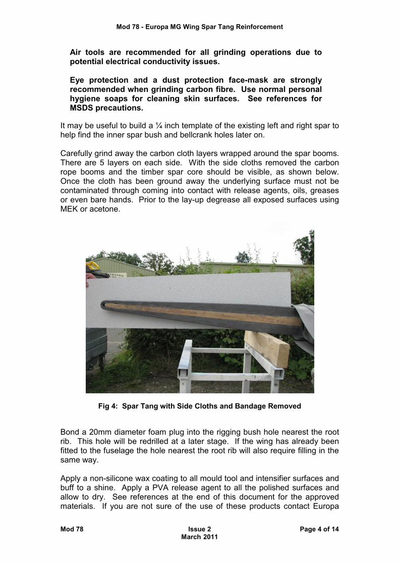
Air tools are recommended for all grinding operations due to potential electrical conductivity issues. Eye protection and a dust protection face-mask are strongly recommended when grinding carbon fibre. Use normal personal hygiene soaps for cleaning skin surfaces. See references for MSDS precautions.
It may be useful to build a ¼ inch template of the existing left and right spar to help find the inner spar bush and bellcrank holes later on. Carefully grind away the carbon cloth layers wrapped around the spar booms. There are 5 layers on each side. With the side cloths removed the carbon rope booms and the timber spar core should be visible, as shown below. Once the cloth has been ground away the underlying surface must not be contaminated through coming into contact with release agents, oils, greases or even bare hands. Prior to the lay-up degrease all exposed surfaces using MEK or acetone.
Fig 4: Spar Tang with Side Cloths and Bandage Removed
Bond a 20mm diameter foam plug into the rigging bush hole nearest the root rib. This hole will be redrilled at a later stage. If the wing has already been fitted to the fuselage the hole nearest the root rib will also require filling in the same way. Apply a non-silicone wax coating to all mould tool and intensifier surfaces and buff to a shine. Apply a PVA release agent to all the polished surfaces and allow to dry. See references at the end of this document for the approved materials. If you are not sure of the use of these products contact Europa
Mod 78 - Europa MG Wing Spar Tang Reinforcement
Mod 78 Issue 2 Page 5 of 14 March 2011
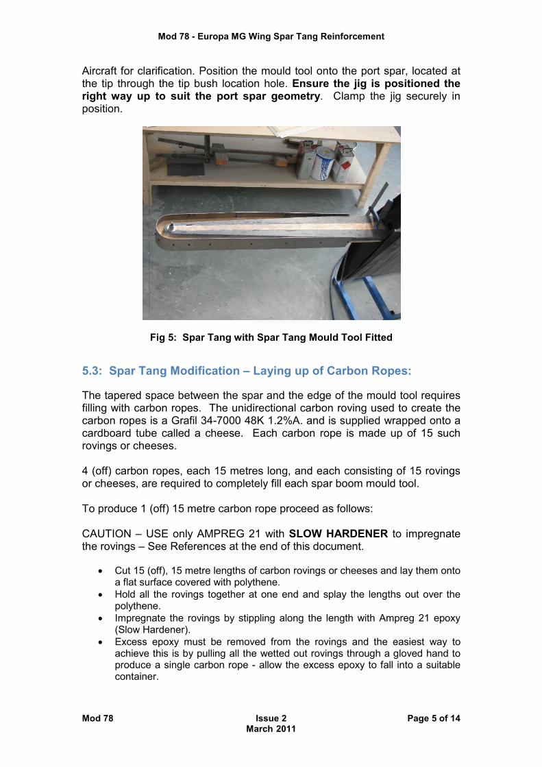
Aircraft for clarification. Position the mould tool onto the port spar, located at the tip through the tip bush location hole. Ensure the jig is positioned the right way up to suit the port spar geometry. Clamp the jig securely in position.
Fig 5: Spar Tang with Spar Tang Mould Tool Fitted
5.3: Spar Tang Modification – Laying up of Carbon Ropes: The tapered space between the spar and the edge of the mould tool requires filling with carbon ropes. The unidirectional carbon roving used to create the carbon ropes is a Grafil 34-7000 48K 1.2%A. and is supplied wrapped onto a cardboard tube called a cheese. Each carbon rope is made up of 15 such rovings or cheeses. 4 (off) carbon ropes, each 15 metres long, and each consisting of 15 rovings or cheeses, are required to completely fill each spar boom mould tool. To produce 1 (off) 15 metre carbon rope proceed as follows: CAUTION – USE only AMPREG 21 with SLOW HARDENER to impregnate the rovings – See References at the end of this document.
• Cut 15 (off), 15 metre lengths of carbon rovings or cheeses and lay them onto a flat surface covered with polythene.
• Hold all the rovings together at one end and splay the lengths out over the polythene.
• Impregnate the rovings by stippling along the length with Ampreg 21 epoxy (Slow Hardener).
• Excess epoxy must be removed from the rovings and the easiest way to achieve this is by pulling all the wetted out rovings through a gloved hand to produce a single carbon rope - allow the excess epoxy to fall into a suitable container.
Mod 78 - Europa MG Wing Spar Tang Reinforcement
Mod 78 Issue 2 Page 6 of 14 March 2011
Splicing technique:
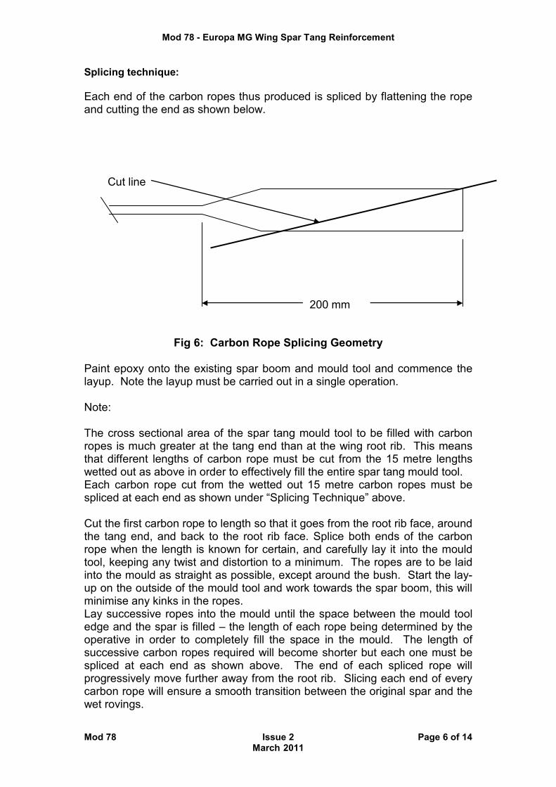
Each end of the carbon ropes thus produced is spliced by flattening the rope and cutting the end as shown below.
Fig 6: Carbon Rope Splicing Geometry
Paint epoxy onto the existing spar boom and mould tool and commence the layup. Note the layup must be carried out in a single operation. Note: The cross sectional area of the spar tang mould tool to be filled with carbon ropes is much greater at the tang end than at the wing root rib. This means that different lengths of carbon rope must be cut from the 15 metre lengths wetted out as above in order to effectively fill the entire spar tang mould tool. Each carbon rope cut from the wetted out 15 metre carbon ropes must be spliced at each end as shown under “Splicing Technique” above. Cut the first carbon rope to length so that it goes from the root rib face, around the tang end, and back to the root rib face. Splice both ends of the carbon rope when the length is known for certain, and carefully lay it into the mould tool, keeping any twist and distortion to a minimum. The ropes are to be laid into the mould as straight as possible, except around the bush. Start the lay-up on the outside of the mould tool and work towards the spar boom, this will minimise any kinks in the ropes. Lay successive ropes into the mould until the space between the mould tool edge and the spar is filled – the length of each rope being determined by the operative in order to completely fill the space in the mould. The length of successive carbon ropes required will become shorter but each one must be spliced at each end as shown above. The end of each spliced rope will progressively move further away from the root rib. Slicing each end of every carbon rope will ensure a smooth transition between the original spar and the wet rovings.
200 mm
Cut line

Mod 78 - Europa MG Wing Spar Tang Reinforcement
Mod 78 Issue 2 Page 7 of 14 March 2011
Fig 7: Carbon Rope Lay-up Showing Tapered Void to be Filled
Smooth each layer into place using a wooden spatula or similar tool and ensure there are no voids between subsequent layers. The carbon ropes should be packed in quite tight and should be level with the spar tang width when complete. Once the carbon ropes are smoothly pressed into place using a tongue depressor or spatula tool, clamp the intensifier board onto the spar to squeeze it all together. Allow to cure for 24 hours. Once cured, remove the intensifier and mould tool and inspect the layup for any voids. Ensure the final layup is not proud of the existing spar width
Fig 8: Carbon Rope Lay-up in Progress

Mod 78 - Europa MG Wing Spar Tang Reinforcement
Mod 78 Issue 2 Page 8 of 14 March 2011
Fig 9: Carbon Rope Lay-up Complete and Intensifier Board in Position
5.4: Spar Tang Modification – Truncating Starboard Tang:
5.4.1: Introduction: This secondary action is required in order to prevent a foul between the end of the starboard wing spar tang and the aileron bellcrank support bracket on the port wing when rigging the aircraft.
5.4.2: Truncating Starboard Spar Tang: Measure 30 mm from the spar tang hole centreline and mark the cut-off line square to the end of the tang – See Fig. 10. Cut off the end of the tang using a hacksaw or diamond cutter. The latter is the preferred option. Care should be taken not to delaminate the spar tang carbon ropes. Inspect for damage or delamination of the spar tang carbon ropes. Radius the 4 sides of the tang end (2mm max.) in order to facilitate the cloth lay-up in Section 5.5.

Mod 78 - Europa MG Wing Spar Tang Reinforcement
Mod 78 Issue 2 Page 9 of 14 March 2011
Fig. 10: Truncated Starboard Spar Tang prior to Cloth Lay-up:
5.5: Spar Tang Modification – Cloth Lay-up: Support the wing horizontally ensuring there is complete access around the spar boom. Scuff sand all four sides of the spar boom and the end face. Fill any small voids with wetted out carbon rovings as required to fill the gap completely.
5.5.1: Starboard Wing Spar Tang ONLY: Lay-up 3 layers of 92125 cloth at 0/90 degrees on the cut-off end face of the STARBOARD SPAR TANG ONLY.
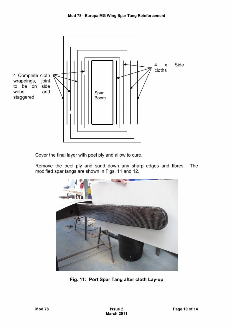
5.5.2: Both Wing Spar Tangs: Lay-up one layer of carbon fibre cloth on each side of the boom. The fibre direction should be at +/- 45º to the boom centre-line. This is best achieved by previously cutting the strips of carbon at 45º from the full roll of cloth. Apply a second layer starting at the top edge of the spar boom and wrap it completely around the spar to butt up to the start point of the cloth. Repeat this procedure until there is a total of 8 layers on each side of the spar with four layers covering the top and bottom spar boom surfaces. Stagger the positions of the joints as shown below. Do not overlap the joints as this may cause a build up of thickness on the two side webs.
Mod 78 - Europa MG Wing Spar Tang Reinforcement
Mod 78 Issue 2 Page 10 of 14 March 2011
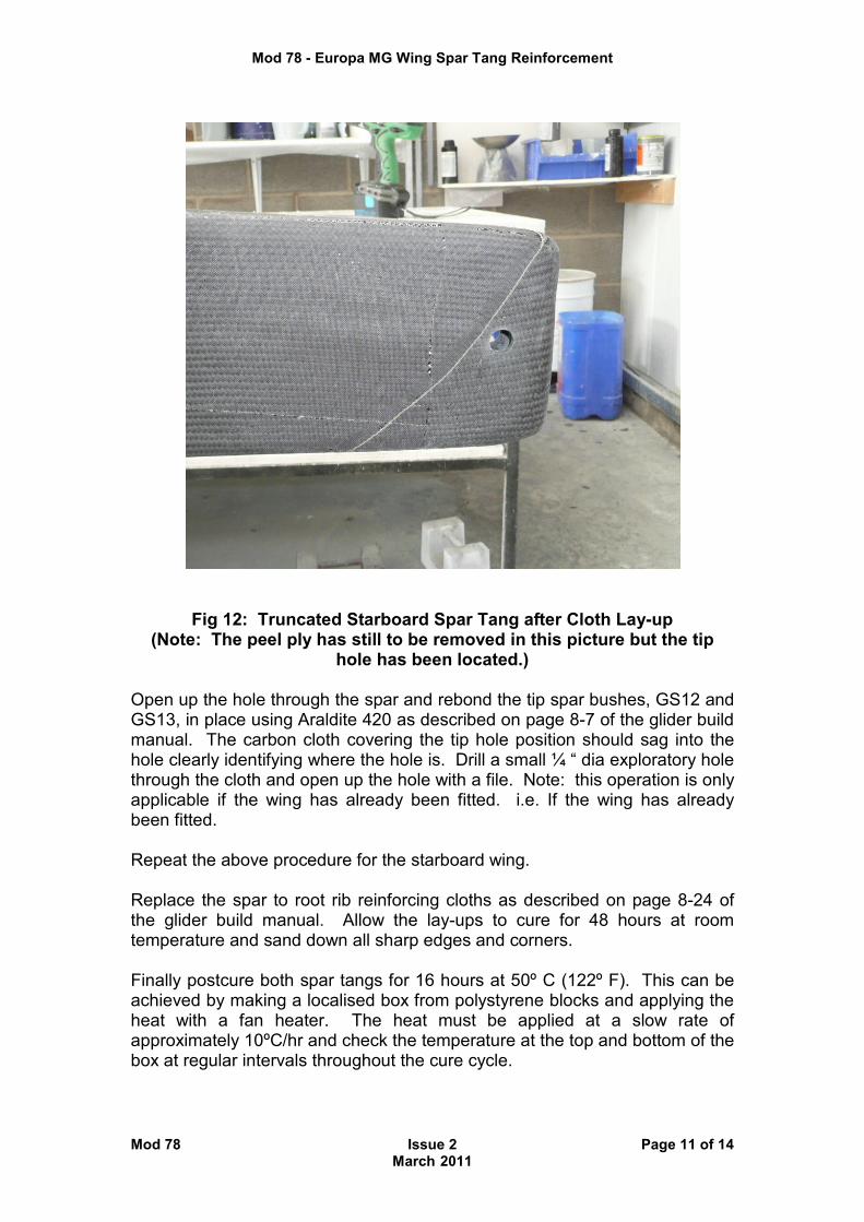
Cover the final layer with peel ply and allow to cure. Remove the peel ply and sand down any sharp edges and fibres. The modified spar tangs are shown in Figs. 11 and 12.
Fig. 11: Port Spar Tang after cloth Lay-up
Spar Boom
4 x Side cloths
4 Complete cloth wrappings, joint to be on side webs and staggered
Mod 78 - Europa MG Wing Spar Tang Reinforcement
Mod 78 Issue 2 Page 11 of 14 March 2011
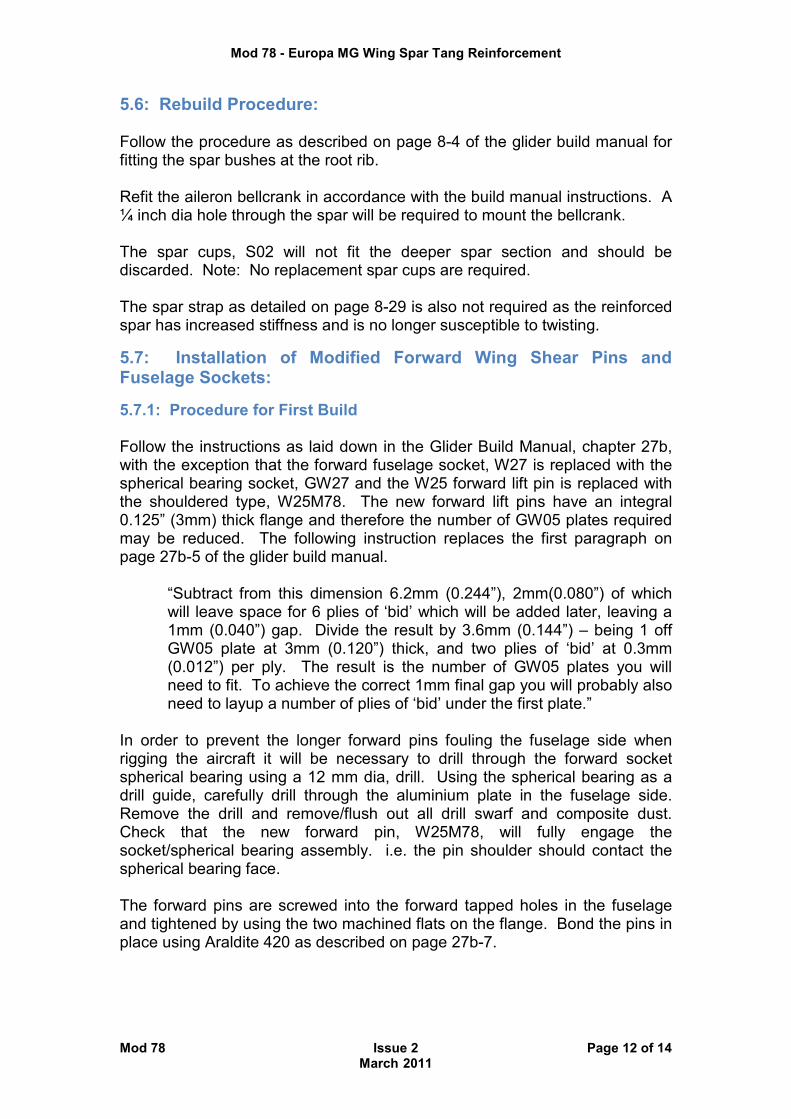
Fig 12: Truncated Starboard Spar Tang after Cloth Lay-up (Note: The peel ply has still to be removed in this picture but the tip
hole has been located.) Open up the hole through the spar and rebond the tip spar bushes, GS12 and GS13, in place using Araldite 420 as described on page 8-7 of the glider build manual. The carbon cloth covering the tip hole position should sag into the hole clearly identifying where the hole is. Drill a small ¼ “ dia exploratory hole through the cloth and open up the hole with a file. Note: this operation is only applicable if the wing has already been fitted. i.e. If the wing has already been fitted. Repeat the above procedure for the starboard wing. Replace the spar to root rib reinforcing cloths as described on page 8-24 of the glider build manual. Allow the lay-ups to cure for 48 hours at room temperature and sand down all sharp edges and corners. Finally postcure both spar tangs for 16 hours at 50º C (122º F). This can be achieved by making a localised box from polystyrene blocks and applying the heat with a fan heater. The heat must be applied at a slow rate of approximately 10ºC/hr and check the temperature at the top and bottom of the box at regular intervals throughout the cure cycle.
Mod 78 - Europa MG Wing Spar Tang Reinforcement
Mod 78 Issue 2 Page 12 of 14 March 2011
5.6: Rebuild Procedure: Follow the procedure as described on page 8-4 of the glider build manual for fitting the spar bushes at the root rib. Refit the aileron bellcrank in accordance with the build manual instructions. A ¼ inch dia hole through the spar will be required to mount the bellcrank. The spar cups, S02 will not fit the deeper spar section and should be discarded. Note: No replacement spar cups are required. The spar strap as detailed on page 8-29 is also not required as the reinforced spar has increased stiffness and is no longer susceptible to twisting.
5.7: Installation of Modified Forward Wing Shear Pins and Fuselage Sockets:
5.7.1: Procedure for First Build Follow the instructions as laid down in the Glider Build Manual, chapter 27b, with the exception that the forward fuselage socket, W27 is replaced with the spherical bearing socket, GW27 and the W25 forward lift pin is replaced with the shouldered type, W25M78. The new forward lift pins have an integral 0.125” (3mm) thick flange and therefore the number of GW05 plates required may be reduced. The following instruction replaces the first paragraph on page 27b-5 of the glider build manual. “Subtract from this dimension 6.2mm (0.244”), 2mm(0.080”) of which
will leave space for 6 plies of ‘bid’ which will be added later, leaving a 1mm (0.040”) gap. Divide the result by 3.6mm (0.144”) – being 1 off GW05 plate at 3mm (0.120”) thick, and two plies of ‘bid’ at 0.3mm (0.012”) per ply. The result is the number of GW05 plates you will need to fit. To achieve the correct 1mm final gap you will probably also need to layup a number of plies of ‘bid’ under the first plate.”
In order to prevent the longer forward pins fouling the fuselage side when rigging the aircraft it will be necessary to drill through the forward socket spherical bearing using a 12 mm dia, drill. Using the spherical bearing as a drill guide, carefully drill through the aluminium plate in the fuselage side. Remove the drill and remove/flush out all drill swarf and composite dust. Check that the new forward pin, W25M78, will fully engage the socket/spherical bearing assembly. i.e. the pin shoulder should contact the spherical bearing face. The forward pins are screwed into the forward tapped holes in the fuselage and tightened by using the two machined flats on the flange. Bond the pins in place using Araldite 420 as described on page 27b-7.
Mod 78 - Europa MG Wing Spar Tang Reinforcement
Mod 78 Issue 2 Page 13 of 14 March 2011
5.7.2: Procedure for retro-fitting onto existing glider and XS wings This procedure applies to glider wings that have previously been fitted and also to the wings of XS and Classic aircraft that have been modified to accept the glider wings. The existing forward sockets, W27, are bolted through the fuselage with the bolt heads on the inside and the socket itself is bonded to the outside of the fuselage side and is further retained by 2 nuts. Remove the 2 nuts retaining each socket. If the sockets do not readily release from the fuselage sides then it will be necessary to apply gentle heat to the sockets in order to soften the flox. Note: in this case it will be necessary to provide a small heatshield in order to prevent damaging the adjacent paint surfaces. Remove the sockets. Remove all traces of the old flox from the area under the old socket position. Apply flox to the area between the new socket, GW27, and the fuselage side and secure the socket in place with the 2 nuts. In order to prevent the longer forward pins fouling the fuselage side when rigging the aircraft it will be necessary to drill through the forward socket spherical bearing using a 12 mm dia, drill. Using the spherical bearing as a drill guide, carefully drill through the aluminium plate in the fuselage side. Remove the drill and remove/flush out all drill swarf and composite dust. Check that the new forward pin, W25M78, will fully engage the socket/spherical bearing assembly. i.e. the pin shoulder should contact the spherical bearing face. Remove the forward wing pins, W25, by applying localised heat to soften the Araldite bond. Replace the pins with the modified W25M78 shouldered pins which can be tightened using the two machined flats on the flange. Bond the pins in place using Araldite 420 as described on page 27b-7.
5.7.3: Rigging Checks: Note: With the longer W25M78 forward pin installed it will be easier to rig the aircraft if the wing tip is positioned slightly forward in order to engage this pin in its socket first and then, rotating the wing backwards again in order to engage the aft pin. With the Glider wings installed onto the aircraft fuselage, carry out the following checks.
• Wing incidence. This should be 2º nose up relative to the fuselage door sill (page 27b-2).
• Wing Dihedral. This should be 2.4º
• Wing Sweep. Check the wings for zero sweep as described on page
27a –2 for retro-fits and 27b-3 for new builds.
Mod 78 - Europa MG Wing Spar Tang Reinforcement
Mod 78 Issue 2 Page 14 of 14 March 2011
6. Useful References: Ampreg 21 Epoxy laminating resin system http://pdf.directindustry.com/pdf/gurit/ampreg-21-epoxy-wet-laminating-system-v7/37817-79049.html Partall Wax for mould release www.fibreglast.com/product/Parting_wax_1016/Mold_Releases Fiber Glast Poly Vinyl Alcohol (PVA) www.fibreglast.com/product/PVA_Release_Film_13/Mold_Releases Mold FAQs www.rexco-usa.com/faq.htm#1 Carbon Fiber Safety Precautions: www.tapplastics.com/uploads/pdf/MSDS%20Carbon%20Fiber%20Sheet.pdf Special Precautions: Airborne carbon fibers or dust are electrically conductive and may create electrical short-circuits that could result in damage to and malfunction of electrical equipment and/or personal injury. Grafil 34-700 Carbon fiber MSDS www.grafil.com/images/pdf/MSDS_Grafil_Continuous_A_Sized_10-2009.pdf