EUROCONTROL EXPERIMENTAL CENTRE ORGANISATION FOR THE SAFETY OF AIR NAVIGATION EUROCONTROL...
130
EUROPEAN ORGANISATION FOR THE SAFETY OF AIR NAVIGATION EUROCONTROL EXPERIMENTAL CENTRE DESIGN AND USER MANUAL FOR BADA EXCEL SPREADSHEETS Issue 2.0 EEC Note No. 13/98 EEC Task D09 EATCHIP Task SDV-D-E7 Issued: May 1998 The information contained in this document is the property of the EUROCONTROL Agency and no part should be reproduced in any form without the Agency’s permission. The views expressed herein do not necessarily reflect the official views or policy of the Agency. EUROCONTROL
-
Upload
nguyenkhuong -
Category
Documents
-
view
237 -
download
0
Transcript of EUROCONTROL EXPERIMENTAL CENTRE ORGANISATION FOR THE SAFETY OF AIR NAVIGATION EUROCONTROL...
EUROPEAN ORGANISATIONFOR THE SAFETY OF AIR NAVIGATION
EUROCONTROL EXPERIMENTAL CENTRE
DESIGN AND USER MANUALFOR
BADA EXCEL SPREADSHEETSIssue 2.0
EEC Note No. 13/98
EEC Task D09EATCHIP Task SDV-D-E7
Issued: May 1998
The information contained in this document is the property of the EUROCONTROL Agency and no part should be reproduced inany form without the Agency’s permission.
The views expressed herein do not necessarily reflect the official views or policy of the Agency.
EUROCONTROL

EEC Note No. 13/98 BADA Excel Spreadsheet Manual
May1998 i
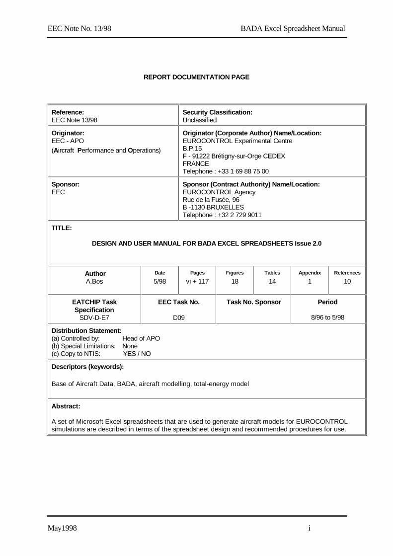
REPORT DOCUMENTATION PAGE
Reference:EEC Note 13/98
Security Classification:Unclassified
Originator:EEC - APO(Aircraft Performance and Operations)
Originator (Corporate Author) Name/Location:EUROCONTROL Experimental CentreB.P.15F - 91222 Brétigny-sur-Orge CEDEXFRANCETelephone : +33 1 69 88 75 00
Sponsor:EEC
Sponsor (Contract Authority) Name/Location:EUROCONTROL AgencyRue de la Fusée, 96B -1130 BRUXELLESTelephone : +32 2 729 9011
TITLE:
DESIGN AND USER MANUAL FOR BADA EXCEL SPREADSHEETS Issue 2.0
AuthorA.Bos
Date
5/98Pages
vi + 117Figures
18Tables
14Appendix
1References
10
EATCHIP TaskSpecification
SDV-D-E7
EEC Task No.
D09
Task No. Sponsor Period
8/96 to 5/98
Distribution Statement:(a) Controlled by: Head of APO(b) Special Limitations: None(c) Copy to NTIS: YES / NO
Descriptors (keywords):
Base of Aircraft Data, BADA, aircraft modelling, total-energy model
Abstract:
A set of Microsoft Excel spreadsheets that are used to generate aircraft models for EUROCONTROLsimulations are described in terms of the spreadsheet design and recommended procedures for use.
EEC Note No. 13/98 BADA Excel Spreadsheet Manual
May1998 ii
This document has been collated by mechanical means. Should there be missing pages, please reportto:
EUROCONTROL Experimental CentrePublications Office
B.P. 1591222 - BRETIGNY-SUR-ORGE CEDEX
France

EEC Note No. 13/98 BADA Excel Spreadsheet Manual
May1998 iii
Design and User Manualfor
BADA Excel SpreadsheetsIssue 2.0
EUROCONTROL Experimental Centre
Summary
A set of Microsoft Excel spreadsheets which are used to generate aircraft models forEUROCONTROL simulations are described in terms of the spreadsheet design, whilerecommended procedures for use are also given.
EEC Note No. 13/98 BADA Excel Spreadsheet Manual
May1998 iv
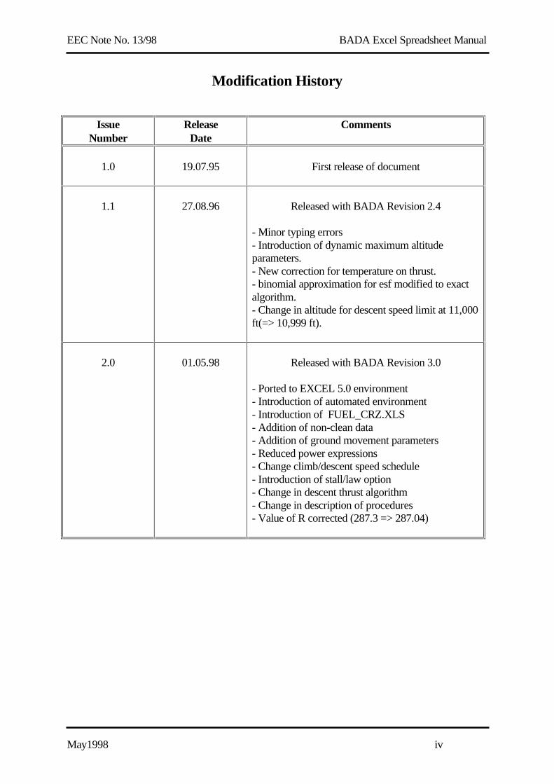
Modification History
IssueNumber
ReleaseDate
Comments
1.0 19.07.95 First release of document
1.1 27.08.96 Released with BADA Revision 2.4
- Minor typing errors- Introduction of dynamic maximum altitudeparameters.- New correction for temperature on thrust.- binomial approximation for esf modified to exactalgorithm.- Change in altitude for descent speed limit at 11,000ft(=> 10,999 ft).
2.0 01.05.98 Released with BADA Revision 3.0
- Ported to EXCEL 5.0 environment- Introduction of automated environment- Introduction of FUEL_CRZ.XLS- Addition of non-clean data- Addition of ground movement parameters- Reduced power expressions- Change climb/descent speed schedule- Introduction of stall/law option- Change in descent thrust algorithm- Change in description of procedures- Value of R corrected (287.3 => 287.04)

EEC Note No. 13/98 BADA Excel Spreadsheet Manual
May1998 v
Table of Contents
1. INTRODUCTION .................................................................................................................1
1.1 Identification and Purpose.............................................................................................................................1
1.2 Document Organisation.................................................................................................................................1
1.3 Referenced Documents...................................................................................................................................2
1.4 Glossary of Acronyms....................................................................................................................................3
2. OVERVIEW...........................................................................................................................4
2.1 Spreadsheet Organisation..............................................................................................................................4
2.2 New and Modified Features...........................................................................................................................7
3. DESIGN..................................................................................................................................9
3.1 BADA.XLS....................................................................................................................................................113.1.1 Standard Atmosphere Block.................................................................................................................123.1.2 Speed Block ..........................................................................................................................................173.1.3 Aircraft Mass Block..............................................................................................................................263.1.4 Engine Thrust Block.............................................................................................................................303.1.5 Drag Block............................................................................................................................................373.1.6 Total-Energy Block...............................................................................................................................423.1.7 Trajectory Block ...................................................................................................................................473.1.8 Fuel Consumption Block ......................................................................................................................553.1.9 Cruise Fuel Block .................................................................................................................................62
3.2 <A/C>.XLS....................................................................................................................................................673.2.1 BADA Coefficient Block......................................................................................................................683.2.2 Selected Trajectory Block .....................................................................................................................753.2.3 Reference Trajectory Blocks .................................................................................................................81
3.3 TRAJECT.XLS ............................................................................................................................................90
3.4 ROCD.XLS ...................................................................................................................................................93
3.5 FUEL.XLS ....................................................................................................................................................95
3.6 FUEL_CRZ.XLS..........................................................................................................................................97
4. PROCEDURES FOR USE .................................................................................................99
4.1 Acquisition of Reference Information ........................................................................................................99
4.2 Initialisation of Aircraft Modelling Report..............................................................................................101
4.3 Initialisation of <A/C>.XLS Spreadsheet .................................................................................................104
4.4 Determination of Climb Thrust and Drag Coefficients ..........................................................................106
4.5 Determination of Thrust Temperature Coefficients ...............................................................................110
4.6 Determination of Fuel Flow Coefficients..................................................................................................111
4.7 Dynamic Maximum Altitude parameters ................................................................................................112
4.8 Buffeting parameters..................................................................................................................................112
4.9 Update of APF and OPF Files...................................................................................................................112
EEC Note No. 13/98 BADA Excel Spreadsheet Manual
May1998 vi
4.10 Create PTF file ......................................................................................................................................113
4.11 Completion of Aircraft Modelling Report ..........................................................................................113
4.12 Use of the SOLV.XLS spreadsheet ......................................................................................................113
5. CONFIGURATION MANAGEMENT...........................................................................114
Appendix A: Configuration Maintenance Logs
EEC Note No. 13/98 BADA Excel Spreadsheet Manual
May 1998 1
1. INTRODUCTION
1.1 Identification and Purpose
This document describes the design and use of the set of BADA Excel Spreadsheets.
BADA, the Base of Aircraft Data, is a collection of ASCII files which specifies performanceparameters and operating procedure parameters for different aircraft types. This information isdesigned for use in trajectory simulation and prediction algorithms within the domain of AirTraffic Management (ATM). The files are maintained by the Eurocontrol Experimental Centre(EEC) at Brétigny-sur-Orge, France. In the last release of BADA, Revision 3.0 in April 1998,files were provided for 67 different aircraft types.
The set of Excel spreadsheets described in this document is used at the EEC for maintaining A/Creference profile data and for calculating BADA coefficients from the reference profiles. Thesespreadsheets replace a previous version described in RD2. This new version of the spreadsheets iscompatible with the BADA model as described in the User Manual for BADA Revision 3.0[RD1].
Both design and user information is contained in this one document since the spreadsheets havebeen designed under the assumption that the same individual will be responsible for both using and maintaining the spreadsheets.
1.2 Document Organisation
This document is presented in five sections including Section 1, the Introduction. A list ofreference documents along with a glossary of acronyms is included in this section.
Section 2, Overview, explains the organisation of the spreadsheets, that is, identifying anddescribing the separate spreadsheets and charts that are used. This section also summarises thenew features in the spreadsheets that distinguishes them from the previous version [RD2].
Section 3, Design, presents a detailed description of each of the Excel spreadsheets and charts. In particular, an explanation of the Excel definitions placed in each spreadsheet cell is provided.
Section 4, Procedures for Use, describes how the spreadsheets are used to prepare a BADAaircraft model.
Section 5, Configuration Management, provides a description of the procedures for testing andmaintaining the spreadsheets. Examples of maintenance logs are then provided as appendices.

EEC Note No. 13/98 BADA Excel Spreadsheet Manual
May 1998 2
1.3 Referenced Documents
RD1 User Manual for the Base of Aircraft Data (BADA) Revision 3.0; EEC Note 6/98,March 1998
RD2 Design and User Manual for BADA Excel Spreadsheets Issue 1.1; EEC Note16/96, August 1996.
RD3 Aircraft Type Designators; ICAO Document 8643, 25th Edition; January 1997.
RD4 Manual of the ICAO Standard Atmosphere, ICAO Document No. 7488, Edition2, 1964
RD5 BADA Modelling Report for B73V Aircraft (Boeing 737-500); EEC CAPODocument Number BADA/AC/B73V/01; 14 April 1995.
RD6 BADA Modelling Report for D328 Aircraft (Dornier 328); EEC CAPODocument Number BADA/AC/D328/01; 17 February 1995.
RD7 BADA Configuration Management Manual; EEC Internal Note 1/APO/1998;April 1998
RD8 Test Report for BADA Excel Spreadsheets; EEC CAPO Document NumberBADA/TN/95/03; May 1995.
RD9 Technical Note on a Low Speed Buffeting Algorithm for BADA Jet Aircraft;EEC APO Document Number TN/96/01; August 1996
RD10 Technical Note on an automated BADA coefficient optimization environment;EEC APO Number TN/97/01; July 1997

EEC Note No. 13/98 BADA Excel Spreadsheet Manual
May 1998 3
1.4 Glossary of Acronyms
A/C Aircraft
APF Airline Procedures File
APO Centre for Aircraft Performance and Operations
ASCII American Standard Code for the Interchange of Information
ATM Air Traffic Management
BADA Base of Aircraft Data
CAS Calibrated Airspeed
CM Configuration Management
EEC Eurocontrol Experimental Centre
ESF Energy Share Factor
FL Flight Level
ICAO International Civil Aviation Organisation
ISA International Standard Atmosphere
MASS Multi-Aircraft Simplified Simulator
OPF Operations Procedures File
rms root-mean-square
ROCD Rate of Climb or Descent
TAS True Air Speed
TEM Total Energy Model
TSFC Thrust Specific Fuel Consumption
EEC Note No. 13/98 BADA Excel Spreadsheet Manual
May 1998 4
<A/C>.XLS
2. OVERVIEW
2.1 Spreadsheet Organisation
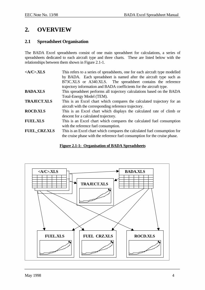
The BADA Excel spreadsheets consist of one main spreadsheet for calculations, a series ofspreadsheets dedicated to each aircraft type and three charts. These are listed below with therelationships between them shown in Figure 2.1-1.
<A/C>.XLS This refers to a series of spreadsheets, one for each aircraft type modelledby BADA. Each spreadsheet is named after the aircraft type such asB73C.XLS or A340.XLS. The spreadsheet contains the referencetrajectory information and BADA coefficients for the aircraft type.
BADA.XLS This spreadsheet performs all trajectory calculations based on the BADATotal-Energy Model (TEM).
TRAJECT.XLS This is an Excel chart which compares the calculated trajectory for anaircraft with the corresponding reference trajectory.
ROCD.XLS This is an Excel chart which displays the calculated rate of climb ordescent for a calculated trajectory.
FUEL.XLS This is an Excel chart which compares the calculated fuel consumptionwith the reference fuel consumption.
FUEL_CRZ.XLS This is an Excel chart which compares the calculated fuel consumption forthe cruise phase with the reference fuel consumption for the cruise phase.
Figure 2.1-1: Organisation of BADA Spreadsheets
BADA.XLS
TRAJECT.XLS
FUEL.XLS ROCD.XLS FUEL CRZ.XLS

EEC Note No. 13/98 BADA Excel Spreadsheet Manual
May 1998 5
The general use of these spreadsheets for the generation of a BADA aircraft model is describedbelow.
(a) For each aircraft type to be modelled, a new instance of the <A/C>.XLS spreadsheet iscreated. This spreadsheet is named after the ICAO designator [RD3] for the aircraft typeunder consideration (e.g. B73C.XLS for Boeing 737-300).
(b) Reference data on the aircraft type (e.g. mass, maximum speeds, dimensions) are enteredinto the <A/C>.XLS spreadsheet along with reference data for climb and descenttrajectories. The reference trajectory data consists of values for distances, times and fuelto climb to or descent from different flight levels with ROCD being an optional entry. Anumber of various trajectories (typically on the order of 10) are entered corresponding todifferent mass, speed or temperature conditions. Each reference trajectory is associatedwith a string identifier (e.g. CL1, CL2, DES1, etc.)
(c) Initial values of BADA coefficients are entered into the <A/C>.XLS spreadsheet. Theseinitial values are based on either standard default values or values corresponding to similaraircraft types previously modelled.
(d) The BADA.XLS spreadsheet is updated to have an external link set to the new<A/C>.XLS spreadsheet. This results in the BADA.XLS spreadsheet importing BADAcoefficients and reference trajectory information from this spreadsheet.
(e) The TRAJECT.XLS, FUEL.XLS, FUEL_CRZ.XLS and ROCD.XLS charts are updatedto have their external links set to the new <A/C>.XLS spreadsheet. This allows forreference information to be imported from the <A/C>.XLS spreadsheet for plotting.
(f) The values of the BADA coefficients are varied in order to obtain a good as match aspossible between the calculated trajectories and the reference trajectories. TheBADA.XLS spreadsheet performs all calculations. Comparisons between calculated andreference trajectories are observed on the TRAJECT.XLS, FUEL.XLS, FUEL_CRZ.XLScharts. The ROCD.XLS chart is also used to observe the calculated rates of climb anddescent. Note that the addition of ROCD data in the <A/C>.XLS spreadsheet is optionalwhich means that a comparison between reference data and calculated data. The inclusionof ROCD data in the <A/C>.XLS spreadsheet is recommended whenever this data isavailable.
The selection of the BADA coefficients is done with the aim of obtaining the best possible matchbetween the calculated and reference trajectories. For this, typically one descent trajectory andseveral climb trajectories are used. Cruise data is also entered in the alst column of the<A/C>.XLS file. This only concerns fuel flow data as a function of altitude.
The descent trajectory represents nominal mass, speed and temperature (ISA) conditions.
The climb trajectories cover a range of mass, speed and temperature conditions. Typically, threemass conditions are used (nominal, minimum, maximum), two speed conditions (nominal and onealternative speed) and three temperature conditions (ISA, ISA+10 and ISA+20).
EEC Note No. 13/98 BADA Excel Spreadsheet Manual
May 1998 6
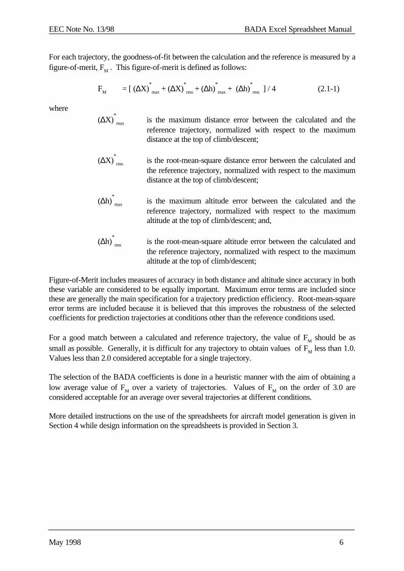
For each trajectory, the goodness-of-fit between the calculation and the reference is measured by afigure-of-merit, FM . This figure-of-merit is defined as follows:
FM = [ (∆X)*
max + (∆X)*
rms + (∆h)*
max + (∆h)*
rms ] / 4 (2.1-1)
where
(∆X)*
max is the maximum distance error between the calculated and thereference trajectory, normalized with respect to the maximumdistance at the top of climb/descent;
(∆X)*
rms is the root-mean-square distance error between the calculated andthe reference trajectory, normalized with respect to the maximumdistance at the top of climb/descent;
(∆h)*
max is the maximum altitude error between the calculated and thereference trajectory, normalized with respect to the maximumaltitude at the top of climb/descent; and,
(∆h)*
rms is the root-mean-square altitude error between the calculated andthe reference trajectory, normalized with respect to the maximumaltitude at the top of climb/descent;
Figure-of-Merit includes measures of accuracy in both distance and altitude since accuracy in boththese variable are considered to be equally important. Maximum error terms are included sincethese are generally the main specification for a trajectory prediction efficiency. Root-mean-squareerror terms are included because it is believed that this improves the robustness of the selectedcoefficients for prediction trajectories at conditions other than the reference conditions used.
For a good match between a calculated and reference trajectory, the value of FM should be assmall as possible. Generally, it is difficult for any trajectory to obtain values of FM less than 1.0.Values less than 2.0 considered acceptable for a single trajectory.
The selection of the BADA coefficients is done in a heuristic manner with the aim of obtaining alow average value of FM over a variety of trajectories. Values of FM on the order of 3.0 areconsidered acceptable for an average over several trajectories at different conditions.
More detailed instructions on the use of the spreadsheets for aircraft model generation is given inSection 4 while design information on the spreadsheets is provided in Section 3.

EEC Note No. 13/98 BADA Excel Spreadsheet Manual
May 1998 7
2.2 New and Modified Features
The main differences between this version and the previous version of the BADA Excelspreadsheets [RD2] are summarised below.
(a) Ported to Excel 5.0/Excel 97 environment
All old .XLC files have been replaced by .XLS files (Excel 5.0). The charts are now imbedded instandard spreadsheets.
(b) Introduction of automated environment
The SOLV.XLS spreadsheet has been created, containing several Visual Basic modules, whichcan be used to find the optimum values of BADA thrust, drag and fuel flow parameters in anautomated way.
(c) Introduction of FUEL_CRZ.XLS
The FUEL_CRZ.XLS spreadsheet was added in order to help find the optimum value for theCf,cr coefficient.
(d) Addition of non-clean data
Non clean data has been added to BADA. This data concerns drag and thrust information for theapproach and landing configurations.
(e) Addition of ground movement parameters
Ground movement parameters were added to help the simulation of airport movements. Theparameters are all directly defined from reference data without the intervention of a calculationprocess.
(f) Reduced power expressions
The reduced power expression is introduced to allow the simulation of reduced power climbs. Thereduction of power is calculated automatically and is a function of the aircraft mass. The choicebetween reduced power yes or no is given to the user. The option yes should be used at all timesduring the modelling process. Only after the process is finished one can chose the option no toinvestigate the influence of this option on the climb profiles
(g) Change climb/descent speed schedule
Several changes have been made to the climb and descent speed schedules for all aircraft types.Details on these changes can be found in RD1.
(h) Introduction of stall/law option
The stall/law option gives the user the possibility to use either the speed law used by the referencedata (law) or the speedschedule defined by BADA based on the stallspeeds (stall). This has only
EEC Note No. 13/98 BADA Excel Spreadsheet Manual
May 1998 8
effect at altitudes below 10,000 ft. Above 10,000 ft the option has no influence. During modellingthe option should be set to law in order to simulate the reference data as close as possible. Theoption stall can be used afterwards, particularly when assessing the ROCD at lower altitudes.
(i) Change in descent thrust algorithm
The thrust algorithm has been simplified. The algorithm no longer uses a correction for mass orspeed. The precise definition can be found in RD1.
(j) Change in description of procedures
Several procedures in the modelling process have been modified. These modified procedures aredescribed in Section 4
(k) Value of R corrected
The gas constant R was defined as having the value 287.3. This has been corrected to the propervalue of 287.04.
EEC Note No. 13/98 BADA Excel Spreadsheet Manual
May 1998 9
3. DESIGN
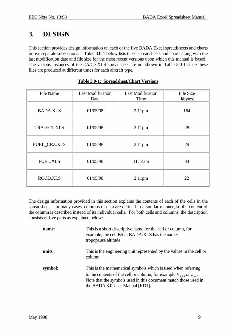
This section provides design information on each of the five BADA Excel spreadsheets and chartsin five separate subsections. Table 3.0-1 below lists these spreadsheets and charts along with thelast modification date and file size for the most recent versions upon which this manual is based. The various instances of the <A/C>.XLS spreadsheet are not shown in Table 3.0-1 since thesefiles are produced at different times for each aircraft type.
Table 3.0-1: Spreadsheet/Chart Versions
File Name Last ModificationDate
Last ModificationTime
File Size[kbytes]
BADA.XLS 01/05/98 2:11pm 164
TRAJECT.XLS 01/05/98 2:11pm 28
FUEL_CRZ.XLS 01/05/98 2:11pm 29
FUEL.XLS 01/05/98 11:14am 34
ROCD.XLS 01/05/98 2:11pm 22
The design information provided in this section explains the contents of each of the cells in thespreadsheets. In many cases, columns of data are defined in a similar manner, so the content ofthe column is described instead of its individual cells. For both cells and columns, the descriptionconsists of five parts as explained below:
name: This is a short descriptive name for the cell or column, forexample, the cell B5 in BADA.XLS has the name:tropopause altitude
units: This is the engineering unit represented by the values in the cell orcolumn.
symbol: This is the mathematical symbols which is used when referringto the contents of the cell or column, for example VTAS or ztrop. Note that the symbols used in this document match those used inthe BADA 3.0 User Manual [RD1].
EEC Note No. 13/98 BADA Excel Spreadsheet Manual
May 1998 10
description: this is a short description of the cell contents including whereappropriate a mathematical representation,example: ztrop = 11000 + 100 ∆T / 6.5In some cases a reference to the BADA User Manual is included.
Excel definition: this is the Excel code that is written into the cell or columnexample: B5 = 11000 + 1000*$A$5/6.5
At this point, it is worth noting two items concerning Excel syntax:
(a) All Excel cells are defined by a column letter (A, B, C, ...) and a row number (1,2, 3, ...). Code placed in a cell can refer to the contents of other cells using eitherrelative or absolute addressing where the dollar symbols “$” is used to indicate anabsolute address.
(b) Values are imported from external spreadsheets using the notation:
<spreadsheet_name>!<cell_address>
Some special notation is used for describing the Excel code placed in columns, that is, the symbol{n} is used to refer to a row number the same as the current row number.
As an example, cells in the column M can be defined as functions of the cells in the same row butcolumn K as follows:
M{n} = K{n}*.5151
Similarly a cell in column AO can be defined to be a function of the cell below it in the samecolumn:
AO{n} = AO{n+1} + $AG{n}/60
EEC Note No. 13/98 BADA Excel Spreadsheet Manual
May 1998 11
3.1 BADA.XLS
The BADA.XLS spreadsheet is responsible for calculating a climb or descent trajectory based onthe total-energy model and the BADA coefficients for a particular aircraft.
The spreadsheet has one external link to the spreadsheet containing the aircraft specificinformation (i.e. BADA coefficients and reference profiles). This link can be set to any one of the<A/C_code>.XLS spreadsheets in order to calculate trajectories for one of the supported aircrafttypes.
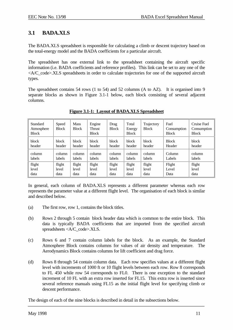
The spreadsheet contains 54 rows (1 to 54) and 52 columns (A to AZ). It is organised into 9separate blocks as shown in Figure 3.1-1 below, each block consisting of several adjacentcolumns.
Figure 3.1-1: Layout of BADA.XLS Spreadsheet
StandardAtmosphereBlock
SpeedBlock
MassBlock
EngineThrustBlock
DragBlock
TotalEnergyBlock
TrajectoryBlock
FuelConsumptionBlock
Cruise FuelConsumptionBlock
blockheader
blockheader
blockheader
blockheader
blockheader
blockheader
blockheader
BlockHeader
blockheader
columnlabels
columnlabels
columnlabels
columnlabels
columnlabels
columnlabels
columnlabels
ColumnLabels
columnlabels
flightleveldata
flightleveldata
flightleveldata
flightleveldata
flightleveldata
flightleveldata
flightleveldata
FlightLevelData
flightleveldata
In general, each column of BADA.XLS represents a different parameter whereas each rowrepresents the parameter value at a different flight level. The organisation of each block is similarand described below.
(a) The first row, row 1, contains the block titles.
(b) Rows 2 through 5 contain block header data which is common to the entire block. Thisdata is typically BADA coefficients that are imported from the specified aircraftspreadsheets <A/C_code>.XLS.
(c) Rows 6 and 7 contain column labels for the block. As an example, the StandardAtmosphere Block contains columns for values of air density and temperature. TheAerodynamics Block contains columns for lift coefficient and drag force.
(d) Rows 8 through 54 contain column data. Each row specifies values at a different flightlevel with increments of 1000 ft or 10 flight levels between each row. Row 8 correspondsto FL 450 while row 54 corresponds to FL0. There is one exception to the standardincrement of 10 FL with an extra row inserted for FL15. This extra row is inserted sinceseveral reference manuals using FL15 as the initial flight level for specifying climb ordescent performance.
The design of each of the nine blocks is described in detail in the subsections below.
EEC Note No. 13/98 BADA Excel Spreadsheet Manual
May 1998 12
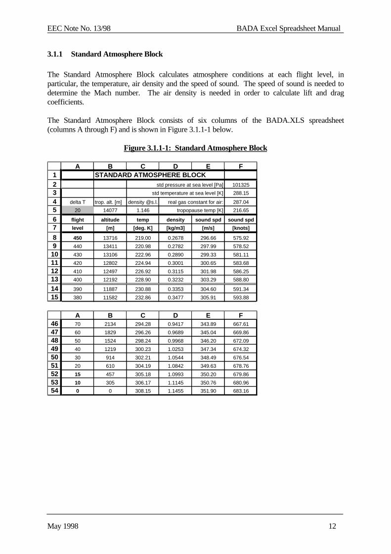
3.1.1 Standard Atmosphere Block
The Standard Atmosphere Block calculates atmosphere conditions at each flight level, inparticular, the temperature, air density and the speed of sound. The speed of sound is needed todetermine the Mach number. The air density is needed in order to calculate lift and dragcoefficients.
The Standard Atmosphere Block consists of six columns of the BADA.XLS spreadsheet(columns A through F) and is shown in Figure 3.1.1-1 below.
Figure 3.1.1-1: Standard Atmosphere Block
1234567
89
101112131415
A B C D E FSTANDARD ATMOSPHERE BLOCK
std pressure at sea level [Pa] 101325
std temperature at sea level [K] 288.15
delta T trop. alt. [m] density @s.l. real gas constant for air: 287.04
20 14077 1.146 tropopause temp [K] 216.65
flight altitude temp density sound spd sound spd
level [m] [deg. K] [kg/m3] [m/s] [knots]
450 13716 219.00 0.2678 296.66 575.92
440 13411 220.98 0.2782 297.99 578.52
430 13106 222.96 0.2890 299.33 581.11
420 12802 224.94 0.3001 300.65 583.68
410 12497 226.92 0.3115 301.98 586.25
400 12192 228.90 0.3232 303.29 588.80
390 11887 230.88 0.3353 304.60 591.34
380 11582 232.86 0.3477 305.91 593.88
464748495051525354
A B C D E F70 2134 294.28 0.9417 343.89 667.61
60 1829 296.26 0.9689 345.04 669.86
50 1524 298.24 0.9968 346.20 672.09
40 1219 300.23 1.0253 347.34 674.32
30 914 302.21 1.0544 348.49 676.54
20 610 304.19 1.0842 349.63 678.76
15 457 305.18 1.0993 350.20 679.86
10 305 306.17 1.1145 350.76 680.96
0 0 308.15 1.1455 351.90 683.16

EEC Note No. 13/98 BADA Excel Spreadsheet Manual
May 1998 13
Individual cells in header of the Standard Atmosphere Block are defined below.
F2 name: ISA air pressure at sea levelunits: Pascalssymbol: (P0)ISA
description: a constant specified by the ICAO Standard Atmosphere(ISA) [RD4]
(P0)ISA = 101325
Excel definition: F2 = 101325
F3 name: ISA air temperature at sea levelunits: degrees Kelvin [K]symbol: (T0)ISA
description: a constant specified by the ICAO Standard Atmosphere(ISA) [RD4]
(T0)ISA = 288.15
Excel definition F3 = 288.15
F4 name: real gas constant for airunits: m
2 / (Ks
2)
symbol: R
description: a constant specified by the ICAO Standard Atmosphere(ISA) [RD4]
R = 287.04
Excel definition: F4 = 287.04
F5 name: air temperature above the tropopauseunits: degrees Kelvin [K]symbol: Ttrop
description: a constant specified by the ICAO Standard Atmosphere(ISA) [RD4]
Ttrop = 216.65
Excel definition: F5 = 216.65
EEC Note No. 13/98 BADA Excel Spreadsheet Manual
May 1998 14
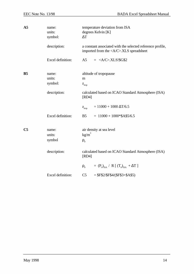
A5 name: temperature deviation from ISAunits: degrees Kelvin [K]symbol: ∆T
description: a constant associated with the selected reference profile,imported from the <A/C>.XLS spreadsheet
Excel definition: A5 = <A/C>.XLS!$G$2
B5 name: altitude of tropopauseunits: msymbol: ztrop
description: calculated based on ICAO Standard Atmosphere (ISA) [RD4]
ztrop = 11000 + 1000 ∆T/6.5
Excel definition: B5 = 11000 + 1000*$A$5/6.5
C5 name: air density at sea levelunits: kg/m
3
symbol ρ0
description: calculated based on ICAO Standard Atmosphere (ISA)[RD4]
ρ0 = (P0)ISA / R [ (T0)ISA + ∆T ]
Excel definition: C5 = $F$2/$F$4/($F$3+$A$5)

EEC Note No. 13/98 BADA Excel Spreadsheet Manual
May 1998 15
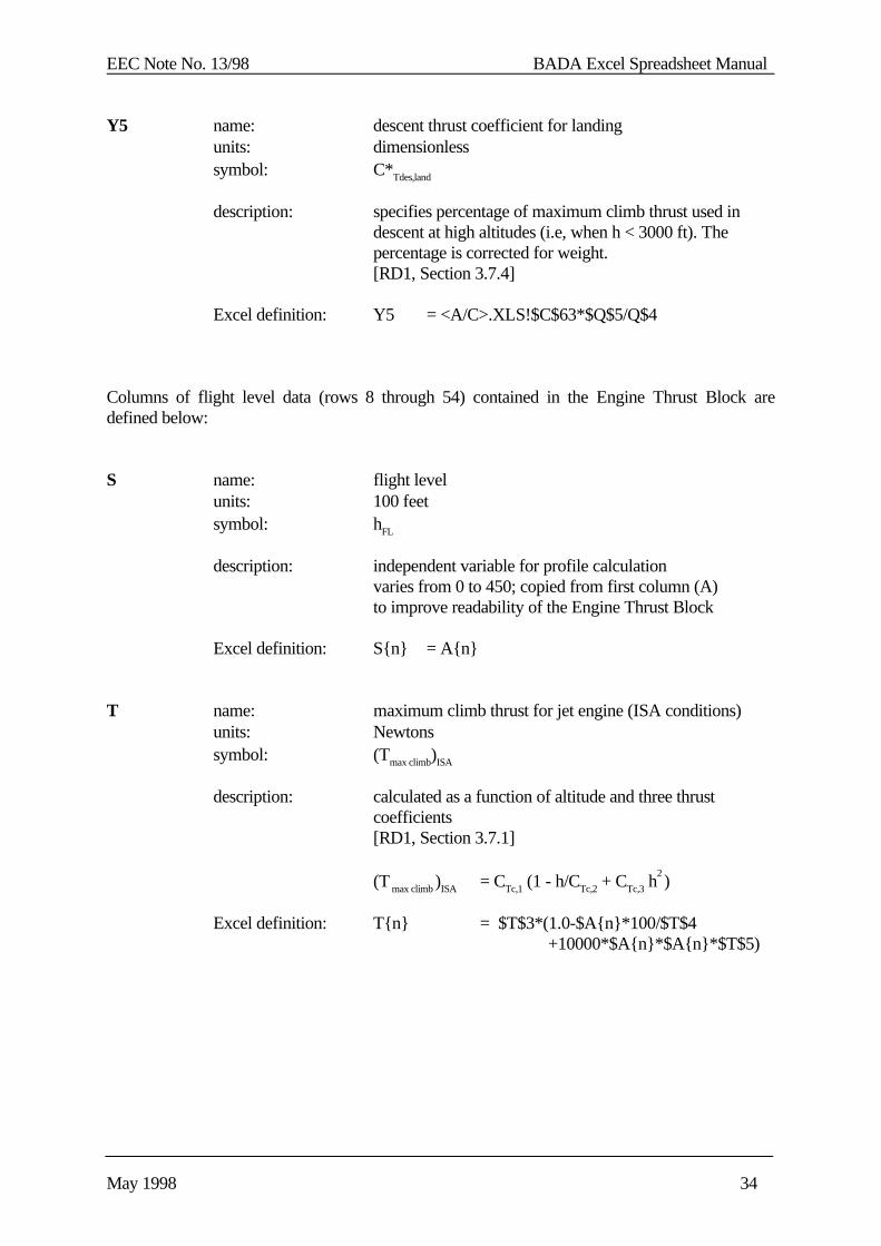
Columns of flight level data (rows 8 through 54) contained in the Standard Atmosphere Block aredefined below:
A name: flight levelunits: 100 feetsymbol: hFL
description: independent variable for trajectory calculationvaries from 0 to 450 with increment of 10 (46 values)additional value for hFL =15 (total of 47 values)
Excel definition: A8 = 450for 9 ≥ n ≥ 51
A{n}= A{n-1} -10A52 = 15A53 = 10A54 = 0
Note: Fields A8, A52, A54 and A54 are highlighted in boldsince these fields do not have the same definition as theother fields in the column.
B name: altitude above sea levelunits: msymbol: z
description: conversion of flight level to metric units
z = 30.48 hFL
Excel definition: B{n} = 30.48*A{n}
C name: air temperatureunits: degrees Kelvin [K]symbol: T
description: calculated based in ICAO Standard Atmosphere (ISA)[RD4]
if z < ztrop
then T = (T0)ISA - 0.0065z + ∆Telse T = Ttrop
Excel definition: C{n} = IF ( $B{n} < $B$5, $F$3 - 0.0065*$B{n} + $A$5, $F$5 )
EEC Note No. 13/98 BADA Excel Spreadsheet Manual
May 1998 16
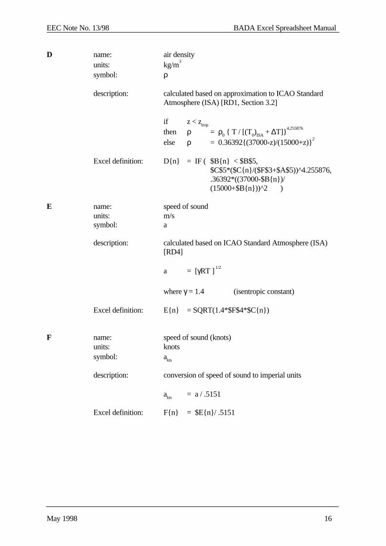
D name: air densityunits: kg/m
3
symbol: ρ
description: calculated based on approximation to ICAO StandardAtmosphere (ISA) [RD1, Section 3.2]
if z < ztrop
then ρ = ρ0 { T / [(T0)ISA + ∆T]}4.255876
else ρ = 0.36392{(37000-z)/(15000+z)}2
Excel definition: D{n} = IF ( $B{n} < $B$5,$C$5*($C{n}/($F$3+$A$5))^4.255876,.36392*((37000-$B{n})/
(15000+$B{n}))^2 )
E name: speed of soundunits: m/ssymbol: a
description: calculated based on ICAO Standard Atmosphere (ISA)[RD4]
a = [γRT ] 1/2
where γ = 1.4 (isentropic constant)
Excel definition: E{n} = SQRT(1.4*$F$4*$C{n})
F name: speed of sound (knots)units: knotssymbol: akts
description: conversion of speed of sound to imperial units
akts = a / .5151
Excel definition: F{n} = $E{n}/ .5151
EEC Note No. 13/98 BADA Excel Spreadsheet Manual
May 1998 17
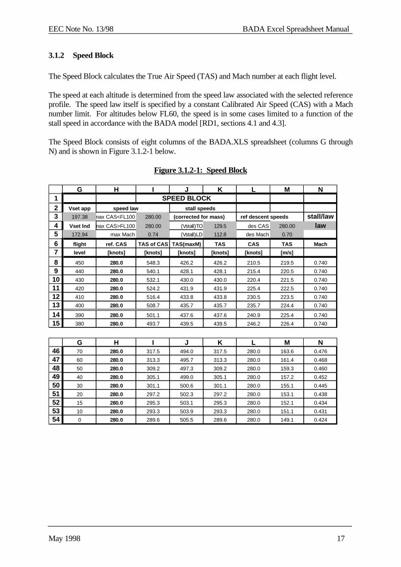
3.1.2 Speed Block
The Speed Block calculates the True Air Speed (TAS) and Mach number at each flight level.
The speed at each altitude is determined from the speed law associated with the selected referenceprofile. The speed law itself is specified by a constant Calibrated Air Speed (CAS) with a Machnumber limit. For altitudes below FL60, the speed is in some cases limited to a function of thestall speed in accordance with the BADA model [RD1, sections 4.1 and 4.3].
The Speed Block consists of eight columns of the BADA.XLS spreadsheet (columns G throughN) and is shown in Figure 3.1.2-1 below.
Figure 3.1.2-1: Speed Block
1234567
89
101112131415
G H I J K L M NSPEED BLOCK
Vset app speed law stall speeds
197.38 max CAS<FL100 280.00 (corrected for mass) ref descent speeds stall/lawVset lnd max CAS>FL100 280.00 (Vstall)TO 129.5 des CAS 280.00 law172.94 max Mach 0.74 (Vstall)LD 112.8 des Mach 0.70
flight ref. CAS TAS of CAS TAS(maxM) TAS CAS TAS Mach
level [knots] [knots] [knots] [knots] [knots] [m/s]
450 280.0 548.3 426.2 426.2 210.5 219.5 0.740
440 280.0 540.1 428.1 428.1 215.4 220.5 0.740
430 280.0 532.1 430.0 430.0 220.4 221.5 0.740
420 280.0 524.2 431.9 431.9 225.4 222.5 0.740
410 280.0 516.4 433.8 433.8 230.5 223.5 0.740
400 280.0 508.7 435.7 435.7 235.7 224.4 0.740
390 280.0 501.1 437.6 437.6 240.9 225.4 0.740
380 280.0 493.7 439.5 439.5 246.2 226.4 0.740
464748495051525354
G H I J K L M N70 280.0 317.5 494.0 317.5 280.0 163.6 0.476
60 280.0 313.3 495.7 313.3 280.0 161.4 0.468
50 280.0 309.2 497.3 309.2 280.0 159.3 0.460
40 280.0 305.1 499.0 305.1 280.0 157.2 0.452
30 280.0 301.1 500.6 301.1 280.0 155.1 0.445
20 280.0 297.2 502.3 297.2 280.0 153.1 0.438
15 280.0 295.3 503.1 295.3 280.0 152.1 0.434
10 280.0 293.3 503.9 293.3 280.0 151.1 0.431
0 280.0 289.6 505.5 289.6 280.0 149.1 0.424
EEC Note No. 13/98 BADA Excel Spreadsheet Manual
May 1998 18
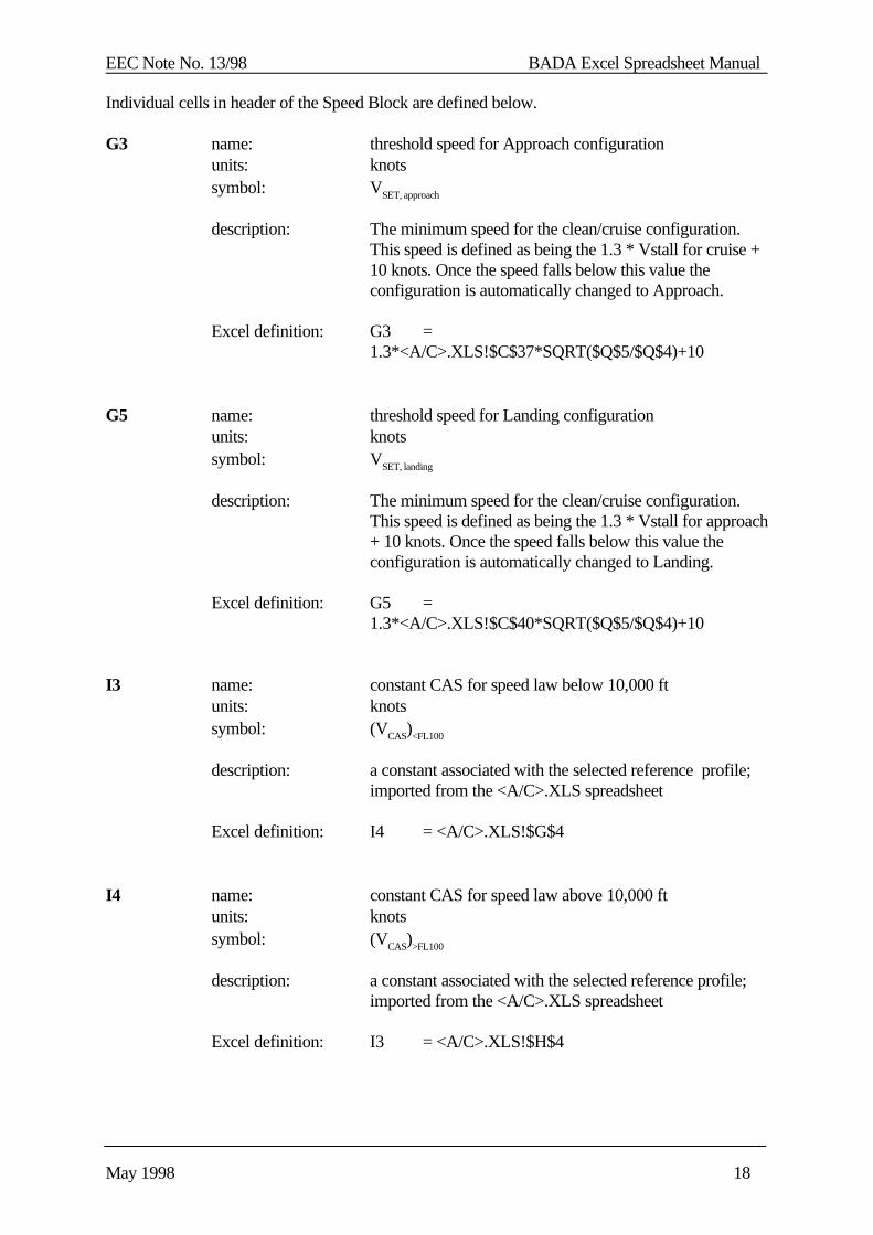
Individual cells in header of the Speed Block are defined below.
G3 name: threshold speed for Approach configurationunits: knotssymbol: VSET, approach
description: The minimum speed for the clean/cruise configuration.This speed is defined as being the 1.3 * Vstall for cruise +10 knots. Once the speed falls below this value theconfiguration is automatically changed to Approach.
Excel definition: G3 =1.3*<A/C>.XLS!$C$37*SQRT($Q$5/$Q$4)+10
G5 name: threshold speed for Landing configurationunits: knotssymbol: VSET, landing
description: The minimum speed for the clean/cruise configuration.This speed is defined as being the 1.3 * Vstall for approach+ 10 knots. Once the speed falls below this value theconfiguration is automatically changed to Landing.
Excel definition: G5 =1.3*<A/C>.XLS!$C$40*SQRT($Q$5/$Q$4)+10
I3 name: constant CAS for speed law below 10,000 ftunits: knotssymbol: (VCAS)<FL100
description: a constant associated with the selected reference profile;imported from the <A/C>.XLS spreadsheet
Excel definition: I4 = <A/C>.XLS!$G$4
I4 name: constant CAS for speed law above 10,000 ftunits: knotssymbol: (VCAS)>FL100
description: a constant associated with the selected reference profile;imported from the <A/C>.XLS spreadsheet
Excel definition: I3 = <A/C>.XLS!$H$4
EEC Note No. 13/98 BADA Excel Spreadsheet Manual
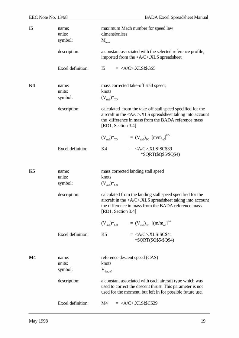
May 1998 19
I5 name: maximum Mach number for speed lawunits: dimensionlesssymbol: Mmax
description: a constant associated with the selected reference profile;imported from the <A/C>.XLS spreadsheet
Excel definition: I5 = <A/C>.XLS!$G$5
K4 name: mass corrected take-off stall speed;units: knotssymbol: (Vstall)*TO
description: calculated from the take-off stall speed specified for theaircraft in the <A/C>.XLS spreadsheet taking into accountthe difference in mass from the BADA reference mass[RD1, Section 3.4]
(Vstall)*TO = (Vstall)TO [m/mref]0.5
Excel definition: K4 = <A/C>.XLS!$C$39 *SQRT($Q$5/$Q$4)
K5 name: mass corrected landing stall speedunits: knotssymbol: (Vstall)*LD
description: calculated from the landing stall speed specified for theaircraft in the <A/C>.XLS spreadsheet taking into accountthe difference in mass from the BADA reference mass[RD1, Section 3.4]
(Vstall)*LD = (Vstall)LD [(m/mref]0.5
Excel definition: K5 = <A/C>.XLS!$C$41 *SQRT($Q$5/$Q$4)
M4 name: reference descent speed (CAS)units: knotssymbol: Vdes,ref
description: a constant associated with each aircraft type which wasused to correct the descent thrust. This parameter is notused for the moment, but left in for possible future use.
Excel definition: M4 = <A/C>.XLS!$C$29
EEC Note No. 13/98 BADA Excel Spreadsheet Manual
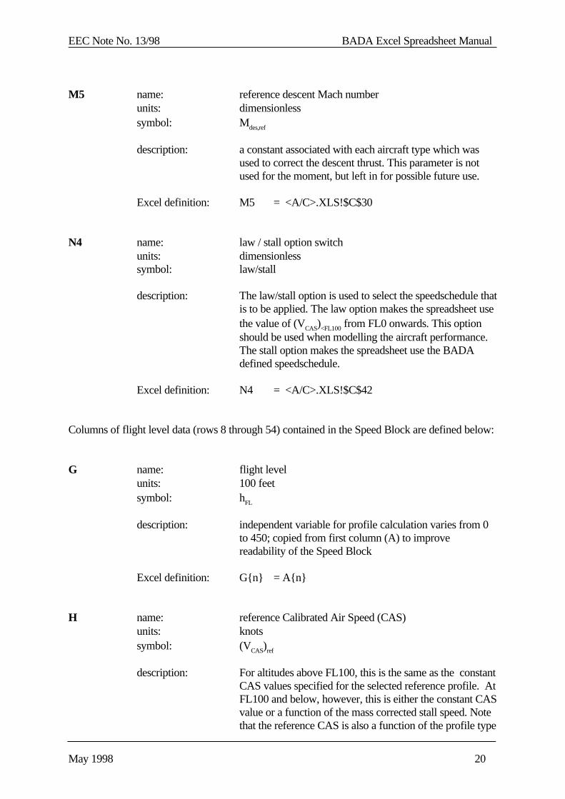
May 1998 20
M5 name: reference descent Mach numberunits: dimensionlesssymbol: Mdes,ref
description: a constant associated with each aircraft type which wasused to correct the descent thrust. This parameter is notused for the moment, but left in for possible future use.
Excel definition: M5 = <A/C>.XLS!$C$30
N4 name: law / stall option switchunits: dimensionlesssymbol: law/stall
description: The law/stall option is used to select the speedschedule thatis to be applied. The law option makes the spreadsheet usethe value of (VCAS)<FL100 from FL0 onwards. This optionshould be used when modelling the aircraft performance.The stall option makes the spreadsheet use the BADAdefined speedschedule.
Excel definition: N4 = <A/C>.XLS!$C$42
Columns of flight level data (rows 8 through 54) contained in the Speed Block are defined below:
G name: flight levelunits: 100 feetsymbol: hFL
description: independent variable for profile calculation varies from 0to 450; copied from first column (A) to improvereadability of the Speed Block
Excel definition: G{n} = A{n}
H name: reference Calibrated Air Speed (CAS)units: knotssymbol: (VCAS)ref
description: For altitudes above FL100, this is the same as the constantCAS values specified for the selected reference profile. AtFL100 and below, however, this is either the constant CASvalue or a function of the mass corrected stall speed. Notethat the reference CAS is also a function of the profile type
EEC Note No. 13/98 BADA Excel Spreadsheet Manual
May 1998 21
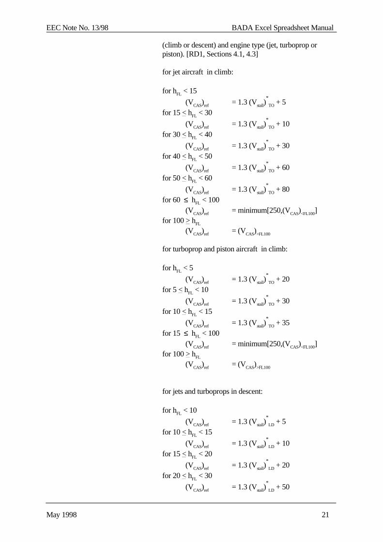
(climb or descent) and engine type (jet, turboprop orpiston). [RD1, Sections 4.1, 4.3]
for jet aircraft in climb:
for hFL < 15
(VCAS)ref = 1.3 (Vstall)*
TO + 5for 15 < hFL < 30
(VCAS)ref = 1.3 (Vstall)*
TO + 10for 30 < hFL < 40
(VCAS)ref = 1.3 (Vstall)*
TO + 30for 40 < hFL < 50
(VCAS)ref = 1.3 (Vstall)*
TO + 60for 50 < hFL < 60
(VCAS)ref = 1.3 (Vstall)*
TO + 80for 60 ≤ hFL < 100
(VCAS)ref = minimum[250,(VCAS)<FL100]for 100 > hFL
(VCAS)ref = (VCAS)>FL100
for turboprop and piston aircraft in climb:
for hFL < 5
(VCAS)ref = 1.3 (Vstall)*
TO + 20for 5 < hFL < 10
(VCAS)ref = 1.3 (Vstall)*
TO + 30for 10 < hFL < 15
(VCAS)ref = 1.3 (Vstall)*
TO + 35for 15 ≤ hFL < 100
(VCAS)ref = minimum[250,(VCAS)<FL100]for 100 > hFL
(VCAS)ref = (VCAS)>FL100
for jets and turboprops in descent:
for hFL < 10
(VCAS)ref = 1.3 (Vstall)*
LD + 5for 10 < hFL < 15
(VCAS)ref = 1.3 (Vstall)*
LD + 10for 15 < hFL < 20
(VCAS)ref = 1.3 (Vstall)*
LD + 20for 20 < hFL < 30
(VCAS)ref = 1.3 (Vstall)*
LD + 50
EEC Note No. 13/98 BADA Excel Spreadsheet Manual
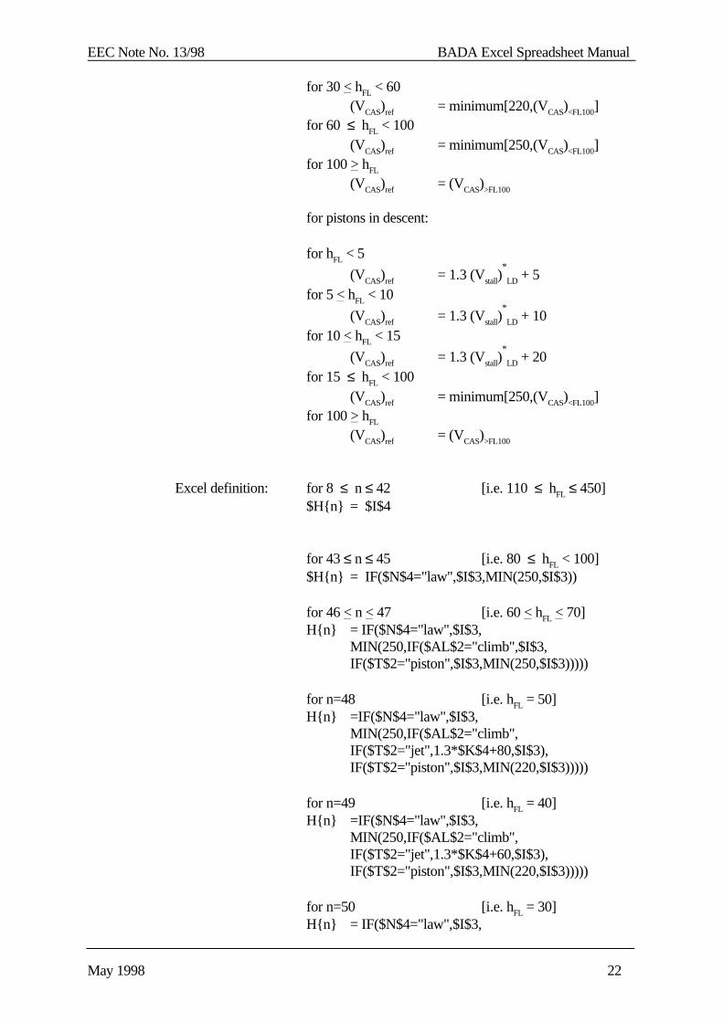
May 1998 22
for 30 < hFL < 60(VCAS)ref = minimum[220,(VCAS)<FL100]
for 60 ≤ hFL < 100(VCAS)ref = minimum[250,(VCAS)<FL100]
for 100 > hFL
(VCAS)ref = (VCAS)>FL100
for pistons in descent:
for hFL < 5
(VCAS)ref = 1.3 (Vstall)*
LD + 5for 5 < hFL < 10
(VCAS)ref = 1.3 (Vstall)*
LD + 10for 10 < hFL < 15
(VCAS)ref = 1.3 (Vstall)*
LD + 20for 15 ≤ hFL < 100
(VCAS)ref = minimum[250,(VCAS)<FL100]for 100 > hFL
(VCAS)ref = (VCAS)>FL100
Excel definition: for 8 ≤ n ≤ 42 [i.e. 110 ≤ hFL ≤ 450]$H{n} = $I$4
for 43 ≤ n ≤ 45 [i.e. 80 ≤ hFL < 100]$H{n} = IF($N$4="law",$I$3,MIN(250,$I$3))
for 46 < n < 47 [i.e. 60 < hFL < 70]H{n} = IF($N$4="law",$I$3,
MIN(250,IF($AL$2="climb",$I$3,IF($T$2="piston",$I$3,MIN(250,$I$3)))))
for n=48 [i.e. hFL = 50]H{n} =IF($N$4="law",$I$3,
MIN(250,IF($AL$2="climb",IF($T$2="jet",1.3*$K$4+80,$I$3),IF($T$2="piston",$I$3,MIN(220,$I$3)))))
for n=49 [i.e. hFL = 40]H{n} =IF($N$4="law",$I$3,
MIN(250,IF($AL$2="climb",IF($T$2="jet",1.3*$K$4+60,$I$3),IF($T$2="piston",$I$3,MIN(220,$I$3)))))
for n=50 [i.e. hFL = 30]H{n} = IF($N$4="law",$I$3,
EEC Note No. 13/98 BADA Excel Spreadsheet Manual
May 1998 23
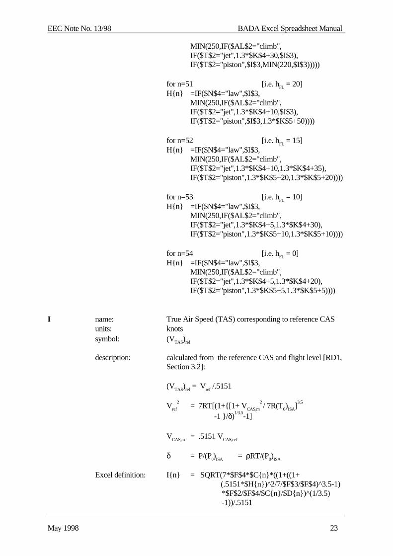
MIN(250,IF($AL$2="climb",IF($T$2="jet",1.3*$K$4+30,$I$3),IF($T$2="piston",$I$3,MIN(220,$I$3)))))
for n=51 [i.e. hFL = 20]H{n} =IF($N$4="law",$I$3,
MIN(250,IF($AL$2="climb",IF($T$2="jet",1.3*$K$4+10,$I$3),IF($T$2="piston",$I$3,1.3*$K$5+50))))
for n=52 [i.e. hFL = 15]H{n} =IF($N$4="law",$I$3,
MIN(250,IF($AL$2="climb",IF($T$2="jet",1.3*$K$4+10,1.3*$K$4+35),IF($T$2="piston",1.3*$K$5+20,1.3*$K$5+20))))
for n=53 [i.e. hFL = 10]H{n} =IF($N$4="law",$I$3,
MIN(250,IF($AL$2="climb",IF($T$2="jet",1.3*$K$4+5,1.3*$K$4+30),IF($T$2="piston",1.3*$K$5+10,1.3*$K$5+10))))
for n=54 [i.e. hFL = 0]H{n} =IF($N$4="law",$I$3,
MIN(250,IF($AL$2="climb",IF($T$2="jet",1.3*$K$4+5,1.3*$K$4+20),IF($T$2="piston",1.3*$K$5+5,1.3*$K$5+5))))
I name: True Air Speed (TAS) corresponding to reference CASunits: knotssymbol: (VTAS)ref
description: calculated from the reference CAS and flight level [RD1,Section 3.2]:
(VTAS)ref = Vref /.5151
Vref
2= 7RT[(1+{[1+ VCAS,m
2 / 7R(T0)ISA]
3.5
-1 }/δ)1/3.5
-1]
VCAS,m = .5151 VCAS,ref
δ = P/(P0)ISA = ρRT/(P0)ISA
Excel definition: I{n} = SQRT(7*$F$4*$C{n}*((1+((1+ (.5151*$H{n})^2/7/$F$3/$F$4)^3.5-1)
*$F$2/$F$4/$C{n}/$D{n})^(1/3.5) -1))/.5151
EEC Note No. 13/98 BADA Excel Spreadsheet Manual
May 1998 24
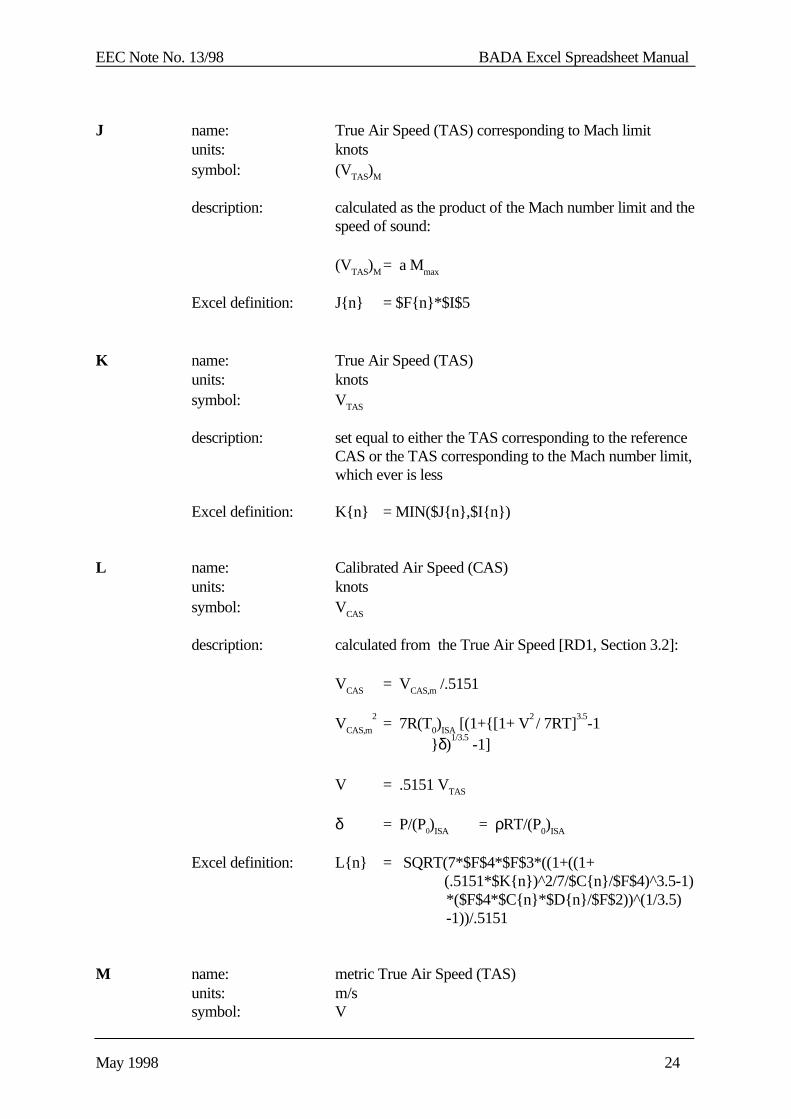
J name: True Air Speed (TAS) corresponding to Mach limitunits: knotssymbol: (VTAS)M
description: calculated as the product of the Mach number limit and thespeed of sound:
(VTAS)M = a Mmax
Excel definition: J{n} = $F{n}*$I$5
K name: True Air Speed (TAS)units: knotssymbol: VTAS
description: set equal to either the TAS corresponding to the referenceCAS or the TAS corresponding to the Mach number limit,which ever is less
Excel definition: K{n} = MIN($J{n},$I{n})
L name: Calibrated Air Speed (CAS)units: knotssymbol: VCAS
description: calculated from the True Air Speed [RD1, Section 3.2]:
VCAS = VCAS,m /.5151
VCAS,m
2= 7R(T0)ISA [(1+{[1+ V
2 / 7RT]
3.5-1
}δ)1/3.5
-1]
V = .5151 VTAS
δ = P/(P0)ISA = ρRT/(P0)ISA
Excel definition: L{n} = SQRT(7*$F$4*$F$3*((1+((1+ (.5151*$K{n})^2/7/$C{n}/$F$4)^3.5-1)
*($F$4*$C{n}*$D{n}/$F$2))^(1/3.5) -1))/.5151
M name: metric True Air Speed (TAS)units: m/ssymbol: V

EEC Note No. 13/98 BADA Excel Spreadsheet Manual
May 1998 25
description: conversion of true airspeed to metric units
V = 0.5151 VTAS
Excel definition: M{n} = K{n}*.5151
N name: Mach numberunits: dimensionlesssymbol: M
description: calculated as ratio of true air speed to speed of sound
M = VTAS / akts
Excel definition: N{n} = $K{n}/$F{n}

EEC Note No. 13/98 BADA Excel Spreadsheet Manual
May 1998 26
3.1.3 Aircraft Mass Block
The Aircraft Mass Block calculates the aircraft mass at each flight level, taking into account thefuel consumed.
The fuel consumed at each flight level is taken from the reference profile data in the <A/C>.XLSspreadsheet. For flight levels for which no reference data is supplied, the fuel consumed iscalculated through linear interpolation.
The Aircraft Mass Block consists of four columns of the BADA.XLS spreadsheet (columns Othrough R) and is shown in Figure 3.1.3-1 below.
Figure 3.1.3-1: Aircraft Mass Block
1234567
89
101112131415
O P Q R AIRCRAFT MASS BLOCK
mass in tonnes
reference 280.00
selected trajectory (initial) 240.00
flight fuel (ref.) fuel (fltr) A/C mass
level [kg] [kg] [kg]
450
440
430
420
410
400 465.00 465.0 240000
390 460.0 239995
380 455.0 239990
464748495051525354
O P Q R70 132.0 239667
60 116.0 239651
50 100.00 100.0 239635
40 71.4 239606
30 42.9 239578
20 14.3 239549
15 0.00 0.0 239535
10 0.0 239535
0 0.0 239535
EEC Note No. 13/98 BADA Excel Spreadsheet Manual
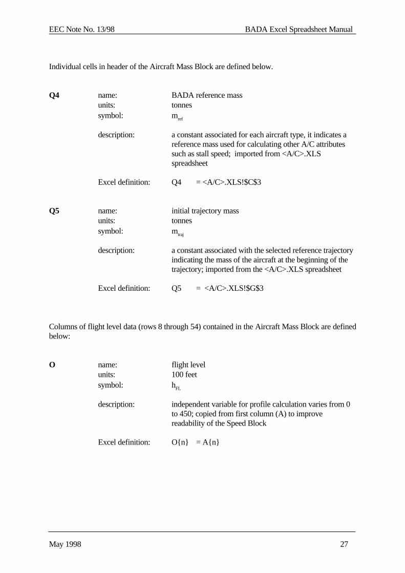
May 1998 27
Individual cells in header of the Aircraft Mass Block are defined below.
Q4 name: BADA reference massunits: tonnessymbol: mref
description: a constant associated for each aircraft type, it indicates areference mass used for calculating other A/C attributessuch as stall speed; imported from <A/C>.XLSspreadsheet
Excel definition: Q4 = <A/C>.XLS!$C$3
Q5 name: initial trajectory massunits: tonnessymbol: mtraj
description: a constant associated with the selected reference trajectoryindicating the mass of the aircraft at the beginning of thetrajectory; imported from the <A/C>.XLS spreadsheet
Excel definition: Q5 = <A/C>.XLS!$G$3
Columns of flight level data (rows 8 through 54) contained in the Aircraft Mass Block are definedbelow:
O name: flight levelunits: 100 feetsymbol: hFL
description: independent variable for profile calculation varies from 0to 450; copied from first column (A) to improvereadability of the Speed Block
Excel definition: O{n} = A{n}
EEC Note No. 13/98 BADA Excel Spreadsheet Manual
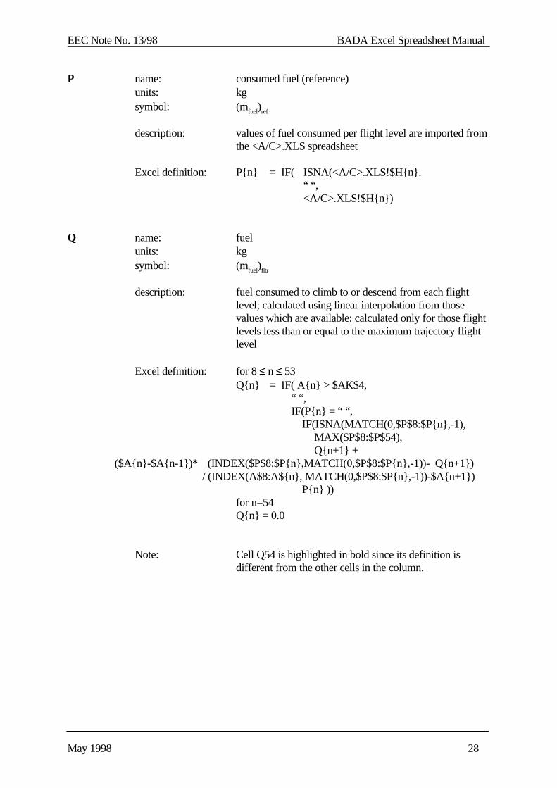
May 1998 28
P name: consumed fuel (reference)units: kgsymbol: (mfuel)ref
description: values of fuel consumed per flight level are imported fromthe <A/C>.XLS spreadsheet
Excel definition: P{n} = IF( ISNA(<A/C>.XLS!$H{n},“ “,<A/C>.XLS!$H{n})
Q name: fuelunits: kgsymbol: (mfuel)fltr
description: fuel consumed to climb to or descend from each flightlevel; calculated using linear interpolation from thosevalues which are available; calculated only for those flightlevels less than or equal to the maximum trajectory flightlevel
Excel definition: for 8 ≤ n ≤ 53Q{n} = IF( A{n} > $AK$4,
“ “, IF(P{n} = “ “, IF(ISNA(MATCH(0,$P$8:$P{n},-1),
MAX($P$8:$P$54), Q{n+1} +
($A{n}-$A{n-1})* (INDEX($P$8:$P{n},MATCH(0,$P$8:$P{n},-1))- Q{n+1}) / (INDEX(A$8:A${n}, MATCH(0,$P$8:$P{n},-1))-$A{n+1})
P{n} ))for n=54Q{n} = 0.0
Note: Cell Q54 is highlighted in bold since its definition isdifferent from the other cells in the column.
EEC Note No. 13/98 BADA Excel Spreadsheet Manual
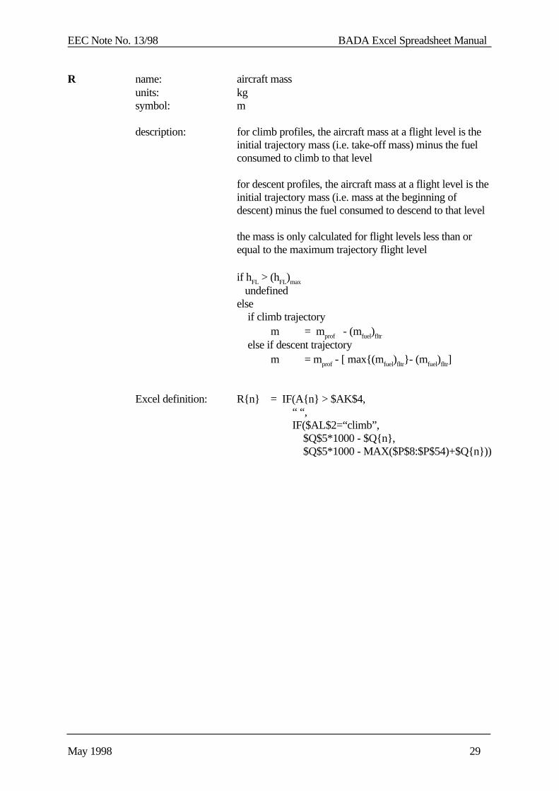
May 1998 29
R name: aircraft massunits: kgsymbol: m
description: for climb profiles, the aircraft mass at a flight level is theinitial trajectory mass (i.e. take-off mass) minus the fuelconsumed to climb to that level
for descent profiles, the aircraft mass at a flight level is theinitial trajectory mass (i.e. mass at the beginning ofdescent) minus the fuel consumed to descend to that level
the mass is only calculated for flight levels less than orequal to the maximum trajectory flight level
if hFL > (hFL)max
undefinedelse if climb trajectory
m = mprof - (mfuel)fltr
else if descent trajectorym = mprof - [ max{(mfuel)fltr}- (mfuel)fltr]
Excel definition: R{n} = IF(A{n} > $AK$4, “ “, IF($AL$2=“climb”, $Q$5*1000 - $Q{n}, $Q$5*1000 - MAX($P$8:$P$54)+$Q{n}))
EEC Note No. 13/98 BADA Excel Spreadsheet Manual
May 1998 30
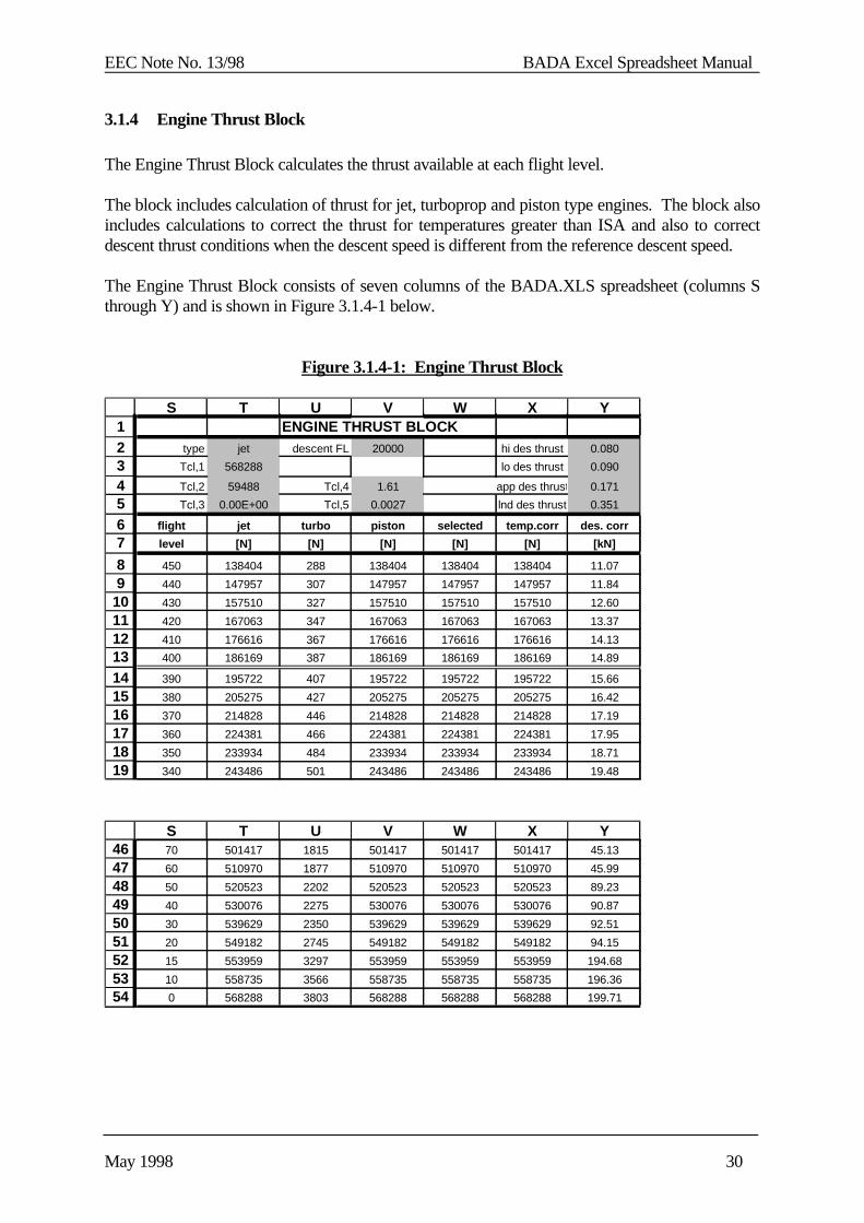
3.1.4 Engine Thrust Block
The Engine Thrust Block calculates the thrust available at each flight level.
The block includes calculation of thrust for jet, turboprop and piston type engines. The block alsoincludes calculations to correct the thrust for temperatures greater than ISA and also to correctdescent thrust conditions when the descent speed is different from the reference descent speed.
The Engine Thrust Block consists of seven columns of the BADA.XLS spreadsheet (columns Sthrough Y) and is shown in Figure 3.1.4-1 below.
Figure 3.1.4-1: Engine Thrust Block
464748495051525354
S T U V W X Y70 501417 1815 501417 501417 501417 45.13
60 510970 1877 510970 510970 510970 45.99
50 520523 2202 520523 520523 520523 89.23
40 530076 2275 530076 530076 530076 90.87
30 539629 2350 539629 539629 539629 92.51
20 549182 2745 549182 549182 549182 94.15
15 553959 3297 553959 553959 553959 194.68
10 558735 3566 558735 558735 558735 196.36
0 568288 3803 568288 568288 568288 199.71
1234567
89
10111213141516171819
S T U V W X YENGINE THRUST BLOCK
type jet descent FL 20000 hi des thrust 0.080
Tcl,1 568288 lo des thrust 0.090
Tcl,2 59488 Tcl,4 1.61 app des thrust 0.171
Tcl,3 0.00E+00 Tcl,5 0.0027 lnd des thrust 0.351
flight jet turbo piston selected temp.corr des. corr
level [N] [N] [N] [N] [N] [kN]
450 138404 288 138404 138404 138404 11.07
440 147957 307 147957 147957 147957 11.84
430 157510 327 157510 157510 157510 12.60
420 167063 347 167063 167063 167063 13.37
410 176616 367 176616 176616 176616 14.13
400 186169 387 186169 186169 186169 14.89
390 195722 407 195722 195722 195722 15.66
380 205275 427 205275 205275 205275 16.42
370 214828 446 214828 214828 214828 17.19
360 224381 466 224381 224381 224381 17.95
350 233934 484 233934 233934 233934 18.71
340 243486 501 243486 243486 243486 19.48

EEC Note No. 13/98 BADA Excel Spreadsheet Manual
May 1998 31
Individual cells in header of the Engine Thrust Block are defined below.
T2 name: engine typeunits: string, either “jet”, “turbo” or “piston”symbol: none
description: a constant associated with with each aircraft type;imported from A/C spreadsheet
Excel definition: T2 = <A/C>.XLS!$C$16
T3 name: first climb thrust coefficientunits: Newtons (jet/piston)
knot-Newton (turbo)symbol: CTc,1
description: a constant associated with with each aircraft type; used tocalculate maximum climb thrust as a function of speed andaltitude; imported from A/C spreadsheet[RD1, Section 3.7.1]
Excel definition: T3 = <A/C>.XLS!$C$19
T4 name: second climb thrust coefficientunits: feetsymbol: CTc,2
description: a constant associated with with each aircraft type; used tocalculate maximum climb thrust as a function of speed andaltitude; imported from A/C spreadsheet[RD1, Section 3.7.1]
Excel definition: T4 = <A/C>.XLS!$C$20

EEC Note No. 13/98 BADA Excel Spreadsheet Manual
May 1998 32
T5 name: third climb thrust coefficientunits: feet
-2 (jet)
Newton (turboprop)knot-Newton (piston)
symbol: CTc,3
description: a constant associated with with each aircraft type; used tocalculate maximum climb thrust as a function of speed andaltitude; imported from A/C spreadsheet[RD1, Section 3.7.1]
Excel definition: T5 = <A/C>.XLS!$C$21
V2 name: descent thrust transition altitudeunits: feetsymbol: hdes
description: a constant associated with with each aircraft type; used todetermine descent thrust from maximum climb thrust; imported from A/C spreadsheet[RD1, Section 3.7.4]
Excel definition: V2 = <A/C>.XLS!$C$28
V4 name: first thrust temperature coefficientunits: degrees Celsiussymbol: CTc,4
description: a constant associated with with each aircraft type; used tocorrect maximum climb thrust for temperature deviationsfrom ISA; imported from A/C spreadsheet[RD1, Section 3.7.1]
Excel definition: V4 = <A/C>.XLS!$C$22
EEC Note No. 13/98 BADA Excel Spreadsheet Manual
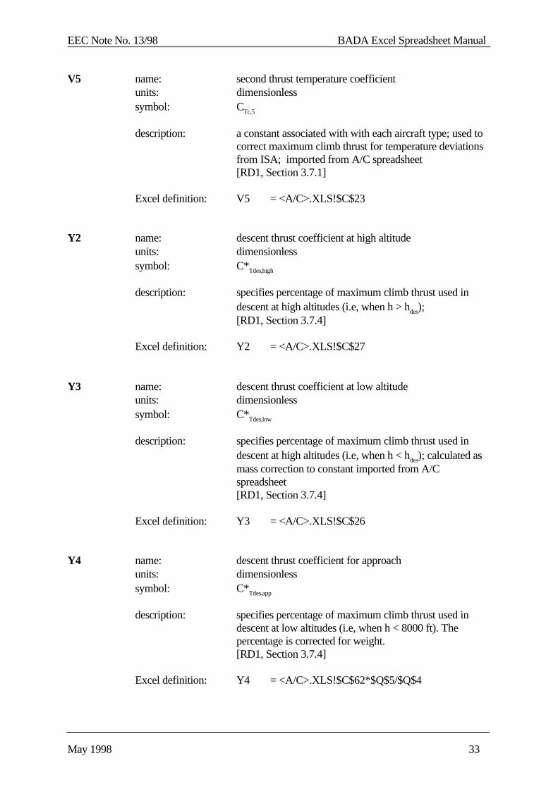
May 1998 33
V5 name: second thrust temperature coefficientunits: dimensionlesssymbol: CTc,5
description: a constant associated with with each aircraft type; used tocorrect maximum climb thrust for temperature deviationsfrom ISA; imported from A/C spreadsheet[RD1, Section 3.7.1]
Excel definition: V5 = <A/C>.XLS!$C$23
Y2 name: descent thrust coefficient at high altitudeunits: dimensionlesssymbol: C*Tdes,high
description: specifies percentage of maximum climb thrust used indescent at high altitudes (i.e, when h > hdes);[RD1, Section 3.7.4]
Excel definition: Y2 = <A/C>.XLS!$C$27
Y3 name: descent thrust coefficient at low altitudeunits: dimensionlesssymbol: C*Tdes,low
description: specifies percentage of maximum climb thrust used indescent at high altitudes (i.e, when h < hdes); calculated asmass correction to constant imported from A/Cspreadsheet[RD1, Section 3.7.4]
Excel definition: Y3 = <A/C>.XLS!$C$26
Y4 name: descent thrust coefficient for approachunits: dimensionlesssymbol: C*Tdes,app
description: specifies percentage of maximum climb thrust used indescent at low altitudes (i.e, when h < 8000 ft). Thepercentage is corrected for weight.[RD1, Section 3.7.4]
Excel definition: Y4 = <A/C>.XLS!$C$62*$Q$5/$Q$4
EEC Note No. 13/98 BADA Excel Spreadsheet Manual
May 1998 34
Y5 name: descent thrust coefficient for landingunits: dimensionlesssymbol: C*Tdes,land
description: specifies percentage of maximum climb thrust used indescent at high altitudes (i.e, when h < 3000 ft). Thepercentage is corrected for weight.[RD1, Section 3.7.4]
Excel definition: Y5 = <A/C>.XLS!$C$63*$Q$5/Q$4
Columns of flight level data (rows 8 through 54) contained in the Engine Thrust Block aredefined below:
S name: flight levelunits: 100 feetsymbol: hFL
description: independent variable for profile calculationvaries from 0 to 450; copied from first column (A)to improve readability of the Engine Thrust Block
Excel definition: S{n} = A{n}
T name: maximum climb thrust for jet engine (ISA conditions)units: Newtonssymbol: (Tmax climb)ISA
description: calculated as a function of altitude and three thrustcoefficients[RD1, Section 3.7.1]
(T max climb )ISA = CTc,1 (1 - h/CTc,2 + CTc,3 h2 )
Excel definition: T{n} = $T$3*(1.0-$A{n}*100/$T$4 +10000*$A{n}*$A{n}*$T$5)
EEC Note No. 13/98 BADA Excel Spreadsheet Manual
May 1998 35
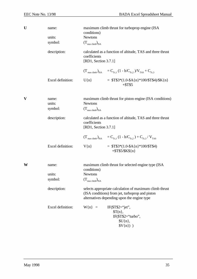
U name: maximum climb thrust for turboprop engine (ISAconditions)
units: Newtonssymbol: (Tmax climb)ISA
description: calculated as a function of altitude, TAS and three thrustcoefficients[RD1, Section 3.7.1]
(T max climb )ISA = CTc,1 (1 - h/CTc,2 )/VTAS + CTc,3
Excel definition: U{n} = $T$3*(1.0-$A{n}*100/$T$4)/$K{n} +$T$5
V name: maximum climb thrust for piston engine (ISA conditions)units: Newtonssymbol: (Tmax climb)ISA
description: calculated as a function of altitude, TAS and three thrustcoefficients[RD1, Section 3.7.1]
(T max climb )ISA = CTc,1 (1 - h/CTc,2 ) + CTc,3 / VTAS
Excel definition: V{n} = $T$3*(1.0-$A{n}*100/$T$4) +$T$5/$K${n}
W name: maximum climb thrust for selected engine type (ISAconditions)
units: Newtonssymbol: (Tmax climb)ISA
description: selects appropriate calculation of maximum climb thrust(ISA conditions) from jet, turboprop and pistonalternatives depending upon the engine type
Excel definition: W{n} = IF($T$2=“jet”, $T(n}, IF($T$2=“turbo”, $U{n}, $V{n}) )
EEC Note No. 13/98 BADA Excel Spreadsheet Manual
May 1998 36
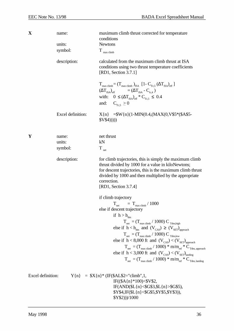
X name: maximum climb thrust corrected for temperatureconditions
units: Newtonssymbol: T max climb
description: calculated from the maximum climb thrust at ISAconditions using two thrust temperature coefficients[RD1, Section 3.7.1]
Tmax climb= (Tmax climb )ISA [1- CTc,5 (∆TISA)eff ](∆TISA)eff = (∆TISA - Ctc,4 )with: 0 ≤ (∆TISA)eff * CTc,5 ≤ 0.4and: CTc,5 > 0
Excel definition: X{n} =$W{n}(1-MIN(0.4,(MAX(0,V$5*($A$5-
$V$4)))))
Y name: net thrustunits: kNsymbol: T net
description: for climb trajectories, this is simply the maximum climbthrust divided by 1000 for a value in kiloNewtons;for descent trajectories, this is the maximum climb thrustdivided by 1000 and then multiplied by the appropriatecorrection.[RD1, Section 3.7.4]
if climb trajectoryTnet = Tmax climb / 1000
else if descent trajectoryif h > hdes
Tnet = (Tmax climb / 1000) C Tdes,high
else if h < hdes and (VCAS) ≥ (VSET)approach
Tnet = (Tmax climb / 1000) C Tdes,low
else if h < 8,000 ft and (VCAS) < (VSET)approach
Tnet = (Tmax climb / 1000) * m/mref * C Tdes, approach
else if h < 3,000 ft and (VCAS) < (VSET)landing
Tnet = (Tmax climb / 1000) * m/mref * C Tdes, landing
Excel definition: Y{n} = $X{n}* (IF($AL$2="climb",1,IF(($A{n}*100)<$V$2,IF(AND($L{n}<$G$3,$L{n}>$G$5),$Y$4,IF($L{n}<$G$5,$Y$5,$Y$3)),$Y$2)))/1000
EEC Note No. 13/98 BADA Excel Spreadsheet Manual
May 1998 37
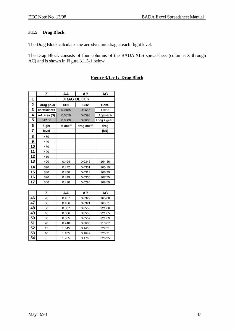
3.1.5 Drag Block
The Drag Block calculates the aerodynamic drag at each flight level.
The Drag Block consists of four columns of the BADA.XLS spreadsheet (columns Z throughAC) and is shown in Figure 3.1.5-1 below.
Figure 3.1.5-1: Drag Block
1234567
89
1011121314151617
Z AA AB AC DRAG BLOCK
drag polar CD0 CD2 Conf.
coefficients 0.0185 0.0656 Clean
ref. area (S) 0.0350 0.0590 Approach
512.00 0.0800 0.0600 Lndg + gear !
flight lift coeff. drag coeff. drag
level [kN]
450
440
430
420
410
400 0.494 0.0345 164.46
390 0.472 0.0331 165.19
380 0.450 0.0318 166.29
370 0.429 0.0306 167.75
360 0.410 0.0295 169.59
464748495051525354
Z AA AB AC70 0.457 0.0322 165.68
60 0.456 0.0321 165.71
50 0.587 0.0553 221.60
40 0.586 0.0553 221.65
30 0.585 0.0552 221.69
20 0.748 0.0680 213.67
15 1.045 0.1456 327.21
10 1.185 0.1642 325.71
0 1.265 0.1760 326.95
EEC Note No. 13/98 BADA Excel Spreadsheet Manual
May 1998 38
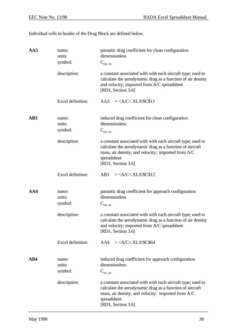
Individual cells in header of the Drag Block are defined below.
AA3 name: parasitic drag coefficient for clean configurationunits: dimensionlesssymbol: CD0, CR
description: a constant associated with with each aircraft type; used tocalculate the aerodynamic drag as a function of air densityand velocity; imported from A/C spreadsheet[RD1, Section 3.6]
Excel definition: AA3 = <A/C>.XLS!$C$11
AB3 name: induced drag coefficient for clean configurationunits: dimensionlesssymbol: CD2, CR
description: a constant associated with with each aircraft type; used tocalculate the aerodynamic drag as a function of aircraftmass, air density, and velocity; imported from A/Cspreadsheet[RD1, Section 3.6]
Excel definition: AB3 = <A/C>.XLS!$C$12
AA4 name: parasitic drag coefficient for approach configurationunits: dimensionlesssymbol: CD0, AP
description: a constant associated with with each aircraft type; used tocalculate the aerodynamic drag as a function of air densityand velocity; imported from A/C spreadsheet[RD1, Section 3.6]
Excel definition: AA4 = <A/C>.XLS!$C$64
AB4 name: induced drag coefficient for approach configurationunits: dimensionlesssymbol: CD2, AP
description: a constant associated with with each aircraft type; used tocalculate the aerodynamic drag as a function of aircraftmass, air density, and velocity; imported from A/Cspreadsheet[RD1, Section 3.6]
EEC Note No. 13/98 BADA Excel Spreadsheet Manual
May 1998 39
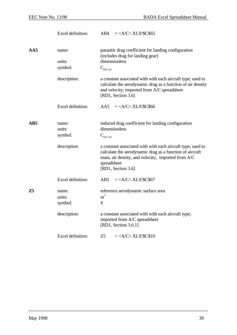
Excel definition: AB4 = <A/C>.XLS!$C$65
AA5 name: parasitic drag coefficient for landing configuration(includes drag for landing gear)
units: dimensionlesssymbol: CD0, LD
description: a constant associated with with each aircraft type; used tocalculate the aerodynamic drag as a function of air densityand velocity; imported from A/C spreadsheet[RD1, Section 3.6]
Excel definition: AA5 = <A/C>.XLS!$C$66
AB5 name: induced drag coefficient for landing configurationunits: dimensionlesssymbol: CD2, LD
description: a constant associated with with each aircraft type; used tocalculate the aerodynamic drag as a function of aircraftmass, air density, and velocity; imported from A/Cspreadsheet[RD1, Section 3.6]
Excel definition: AB5 = <A/C>.XLS!$C$67
Z5 name: reference aerodynamic surface areaunits: m
2
symbol: S
description: a constant associated with with each aircraft type; imported from A/C spreadsheet[RD1, Section 3.6.1]
Excel definition: Z5 = <A/C>.XLS!$C$10
EEC Note No. 13/98 BADA Excel Spreadsheet Manual
May 1998 40
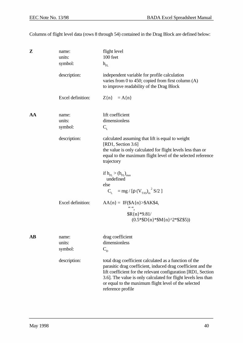
Columns of flight level data (rows 8 through 54) contained in the Drag Block are defined below:
Z name: flight levelunits: 100 feetsymbol: hFL
description: independent variable for profile calculationvaries from 0 to 450; copied from first column (A)to improve readability of the Drag Block
Excel definition: Z{n} = A{n}
AA name: lift coefficientunits: dimensionlesssymbol: CL
description: calculated assuming that lift is equal to weight[RD1, Section 3.6]the value is only calculated for flight levels less than orequal to the maximum flight level of the selected referencetrajectory
if hFL > (hFL)max
undefinedelse CL = mg / [ρ (VTAS)m
2 S/2 ]
Excel definition: AA{n} = IF($A{n}>$AK$4, “ “, $R{n}*9.81/
(0.5*$D{n}*$M{n}^2*$Z$5))
AB name: drag coefficientunits: dimensionlesssymbol: CD
description: total drag coefficient calculated as a function of theparasitic drag coefficient, induced drag coefficient and thelift coefficient for the relevant configuration [RD1, Section3.6]. The value is only calculated for flight levels less thanor equal to the maximum flight level of the selectedreference profile

EEC Note No. 13/98 BADA Excel Spreadsheet Manual
May 1998 41
if hFL > (hFL)max
undefinedif phase = “climb”
CD = CD0,CR + CD2,CR CL 2
else if h > 8,000 ftCD = CD0,CR + CD2,CR CL
2
else if h < 8,000 ft and (VCAS) < (VSET)approach
CD = CD0,AP + CD2,AP CL 2
else if h < 3,000 ft and (VCAS) < (VSET)landing
CD = CD0,LD + CD2,LD CL 2
Excel definition: AB{n} =IF($A{n}>$AK$4,"",IF($AL$2="climb",$AA$3+$AB$3*$AA{n}^2,IF($L{n}>$G$3,$AA$3+$AB$3*$AA{n}^2,IF(AND($L{n}<$G$3,$L{n}>$G$5),$AA$4+$AB$4*$AA{n}^2,$AA$5+$AB$5*$AA{n}^2))))
AC name: aerodynamic dragunits: kNsymbol: D
description: calculated from drag coefficient, reference aerodynamicsurface area and dynamic pressure;[RD1, Section 3.6]the value is only calculated for flight levels less than orequal to the maximum flight level of the selected referenceprofile;
if hFL > (hFL)max
undefinedelse D = [ CD ρ (VTAS)m
2 S /2 ] / 1000
Excel definition: AC{n} = IF($A{n}>$AK$4, “ “, $AB{n}*$D${n}*$M{n}^2*$Z$5/2/1000 )

EEC Note No. 13/98 BADA Excel Spreadsheet Manual
May 1998 42
3.1.6 Total-Energy Block
The Total-Energy Block calculates the rate of climb or descent at each flight level based on thetotal-energy model.
The Total-Energy Block consists of six columns of the BADA.XLS spreadsheet (columns ADthrough AI) and is shown in Figure 3.1.6-1 below.
Figure 3.1.6-1: Total-Energy Model Block
1234567
89
1011121314151617181920
AD AE AF AG AH AI TOTAL ENERGY BLOCK
max pow. red. power reduction
0.150 1.000
flight energy avl. power time step esf ROCD
level [MJ] [kW] [sec] [fpm]
450
440
430
420
410
400 36077 -37071 19.4 1.000 3099
390 35358 -37063 19.4 1.000 3099
380 34640 -37145 19.3 1.000 3106
370 33922 -37318 19.0 1.000 3120
360 33209 -37600 17.2 1.104 3470
350 32558 -38141 16.9 1.104 3520
340 31908 -38778 16.6 1.104 3578
330 31257 -39509 24.2 1.104 3646
464748495051525354
AD AE AF AG AH AI70 7443 -17156 46.3 0.910 1307
60 6657 -16793 78.9 0.913 1284
50 5359 -16116 48.3 0.933 1259
40 4591 -15693 49.5 0.935 1229
30 3825 -15280 81.2 0.937 1199
20 2705 -12318 61.6 0.951 982
15 1971 -11471 43.4 0.965 927
10 1496 -10439 77.8 0.969 848
0 710 -9794 0.0 0.972 798
EEC Note No. 13/98 BADA Excel Spreadsheet Manual
May 1998 43
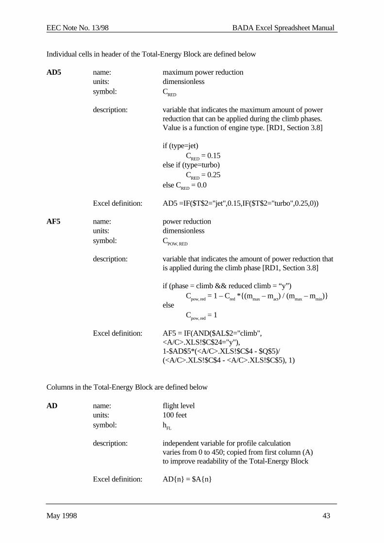
Individual cells in header of the Total-Energy Block are defined below
AD5 name: maximum power reductionunits: dimensionlesssymbol: CRED
description: variable that indicates the maximum amount of powerreduction that can be applied during the climb phases.Value is a function of engine type. [RD1, Section 3.8]
if (type=jet)CRED = 0.15
else if (type=turbo)CRED = 0.25
else CRED = 0.0
Excel definition: AD5 =IF($T$2="jet",0.15,IF($T$2="turbo",0.25,0))
AF5 name: power reductionunits: dimensionlesssymbol: CPOW, RED
description: variable that indicates the amount of power reduction thatis applied during the climb phase [RD1, Section 3.8]
if (phase = climb && reduced climb = “y”)Cpow, red = 1 – Cred *{(m max – mact) / (mmax – mmin)}
elseCpow, red = 1
Excel definition: AF5 = IF(AND($AL$2="climb",<A/C>.XLS!$C$24="y"),1-$AD$5*(<A/C>.XLS!$C$4 - $Q$5)/(<A/C>.XLS!$C$4 - <A/C>.XLS!$C$5), 1)
Columns in the Total-Energy Block are defined below
AD name: flight levelunits: 100 feetsymbol: hFL
description: independent variable for profile calculationvaries from 0 to 450; copied from first column (A)to improve readability of the Total-Energy Block
Excel definition: AD{n} = $A{n}
EEC Note No. 13/98 BADA Excel Spreadsheet Manual
May 1998 44
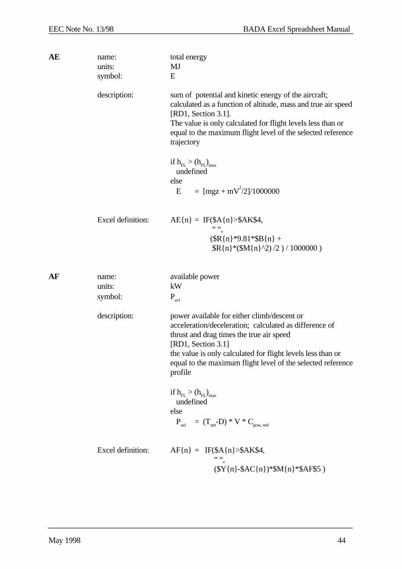
AE name: total energyunits: MJsymbol: E
description: sum of potential and kinetic energy of the aircraft;calculated as a function of altitude, mass and true air speed[RD1, Section 3.1].The value is only calculated for flight levels less than orequal to the maximum flight level of the selected referencetrajectory
if hFL > (hFL)max
undefinedelse E = [mgz + mV
2/2]/1000000
Excel definition: AE{n} = IF($A{n}>$AK$4, “ “, ($R{n}*9.81*$B{n} + $R{n}*($M{n}^2) /2 ) / 1000000 )
AF name: available powerunits: kWsymbol: Pavl
description: power available for either climb/descent oracceleration/deceleration; calculated as difference ofthrust and drag times the true air speed[RD1, Section 3.1]the value is only calculated for flight levels less than orequal to the maximum flight level of the selected referenceprofile
if hFL > (hFL)max
undefinedelse Pavl = (Tnet-D) * V * Cpow, red
Excel definition: AF{n} = IF($A{n}>$AK$4, “ “, ($Y{n}-$AC{n})*$M{n}*$AF$5 )
EEC Note No. 13/98 BADA Excel Spreadsheet Manual
May 1998 45
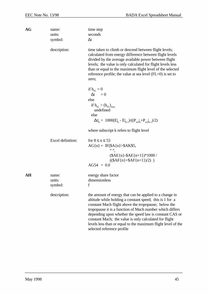
AG name: time stepunits: secondssymbol: ∆t
description: time taken to climb or descend between flight levels;calculated from energy difference between flight levelsdivided by the average available power between flightlevels; the value is only calculated for flight levels lessthan or equal to the maximum flight level of the selectedreference profile; the value at sea level (FL=0) is set tozero;
if hFL = 0 ∆t = 0else if hFL > (hFL)max
undefined else ∆t|k = 1000(E|k - E|k-1)/((Pavl|k+Pavl|k-1)/2)
where subscript k refers to flight level
Excel definition: for 8 ≤ n ≤ 53AG{n} = IF($A{n}>$AK$5,
“ “, ($AE{n}-$AE{n+1})*1000 / (($AF{n}+$AF{n+1})/2) )
AG54 = 0.0
AH name: energy share factorunits: dimensionlesssymbol: f
description: the amount of energy that can be applied to a change inaltitude while holding a constant speed; this is 1 for aconstant Mach flight above the tropopause; below thetropopause it is a function of Mach number which differsdepending upon whether the speed law is constant CAS orconstant Mach; the value is only calculated for flightlevels less than or equal to the maximum flight level of theselected reference profile
EEC Note No. 13/98 BADA Excel Spreadsheet Manual
May 1998 46
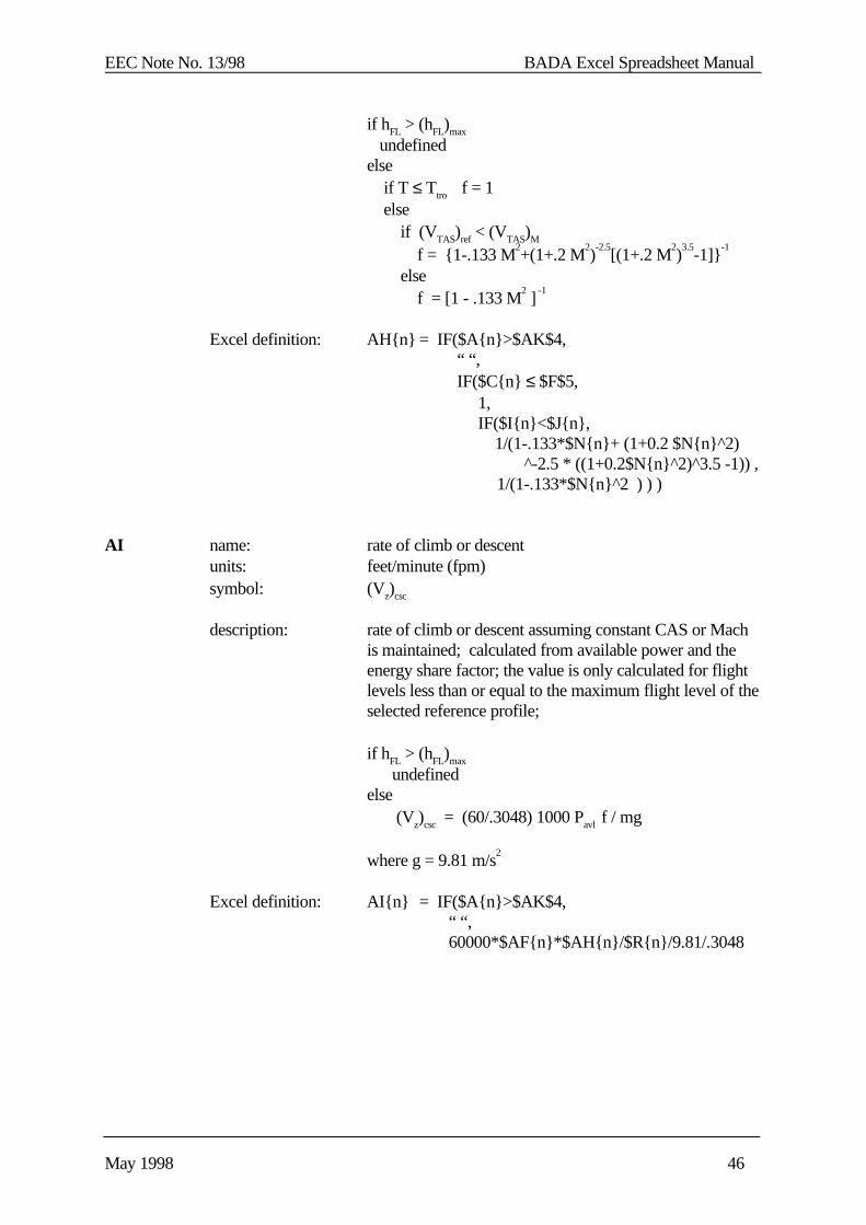
if hFL > (hFL)max
undefinedelse if T ≤ Ttro f = 1 else if (VTAS)ref < (VTAS)M
f = {1-.133 M2+(1+.2 M
2)
-2.5[(1+.2 M
2)
3.5-1]}
-1
else f = [1 - .133 M
2 ]
-1
Excel definition: AH{n} = IF($A{n}>$AK$4, “ “,
IF($C{n} ≤ $F$5, 1, IF($I{n}<$J{n}, 1/(1-.133*$N{n}+ (1+0.2 $N{n}^2)
^-2.5 * ((1+0.2$N{n}^2)^3.5 -1)) , 1/(1-.133*$N{n}^2 ) ) )
AI name: rate of climb or descentunits: feet/minute (fpm)symbol: (Vz)csc
description: rate of climb or descent assuming constant CAS or Machis maintained; calculated from available power and theenergy share factor; the value is only calculated for flightlevels less than or equal to the maximum flight level of theselected reference profile;
if hFL > (hFL)max
undefinedelse (Vz)csc = (60/.3048) 1000 Pavl f / mg
where g = 9.81 m/s2
Excel definition: AI{n} = IF($A{n}>$AK$4, “ “, 60000*$AF{n}*$AH{n}/$R{n}/9.81/.3048

EEC Note No. 13/98 BADA Excel Spreadsheet Manual
May 1998 47
3.1.7 Trajectory Block
The Trajectory Block calculates a trajectory in terms of the time and distance to climb or descentat each flight level. This block also calculates the error between the calculated trajectory and thereference trajectory.
The Trajectory Block consists of seven columns of the BADA.XLS spreadsheet (columns AJthrough AP) and is shown in Figure 3.1.7-1 below.
Figure 3.1.7-1: Trajectory Block
1234567
89
1011121314151617181920
AJ AK AL AM AN AO AP TRAJECTORY BLOCK
B747 DES1 descent dist. [n.m] dist[%TOCD] alt. [ft] alt.[%TOCD]
min FL 15 max error 12.0 10.3 5078 12.7
max FL 400 rms error 10.1 8.6 3539 8.8
max dist. 117 figure of merit 10.1
flight allowed gnd speed distance time dist. error alt.error
level FL [knots] [n. miles] [min] [n. miles] [ft]
450 #N/A
440 #N/A
430 #N/A
420 #N/A
410 #N/A
400 400 480.20 128.17 22.07 11.2 4327
390 390 480.20 125.59 21.75
380 380 480.20 123.00 21.42
370 370 480.19 120.43 21.10
360 360 480.15 117.90 20.79
350 350 482.31 115.60 20.50 11.6 5078
340 340 484.46 113.33 20.22
330 330 486.59 111.08 19.94
464748495051525354
AJ AK AL AM AN AO AP70 70 275.97 23.40 6.10
60 60 272.00 19.87 5.32
50 50 236.04 14.30 4.01 0.8 257
40 40 232.64 11.16 3.20
30 30 229.32 7.99 2.38
20 20 199.85 3.15 1.03
15 15 167.77 0.00 0.00
10 10 156.45 0.00 0.00
0 0 149.22 0.00 0.00
EEC Note No. 13/98 BADA Excel Spreadsheet Manual
May 1998 48
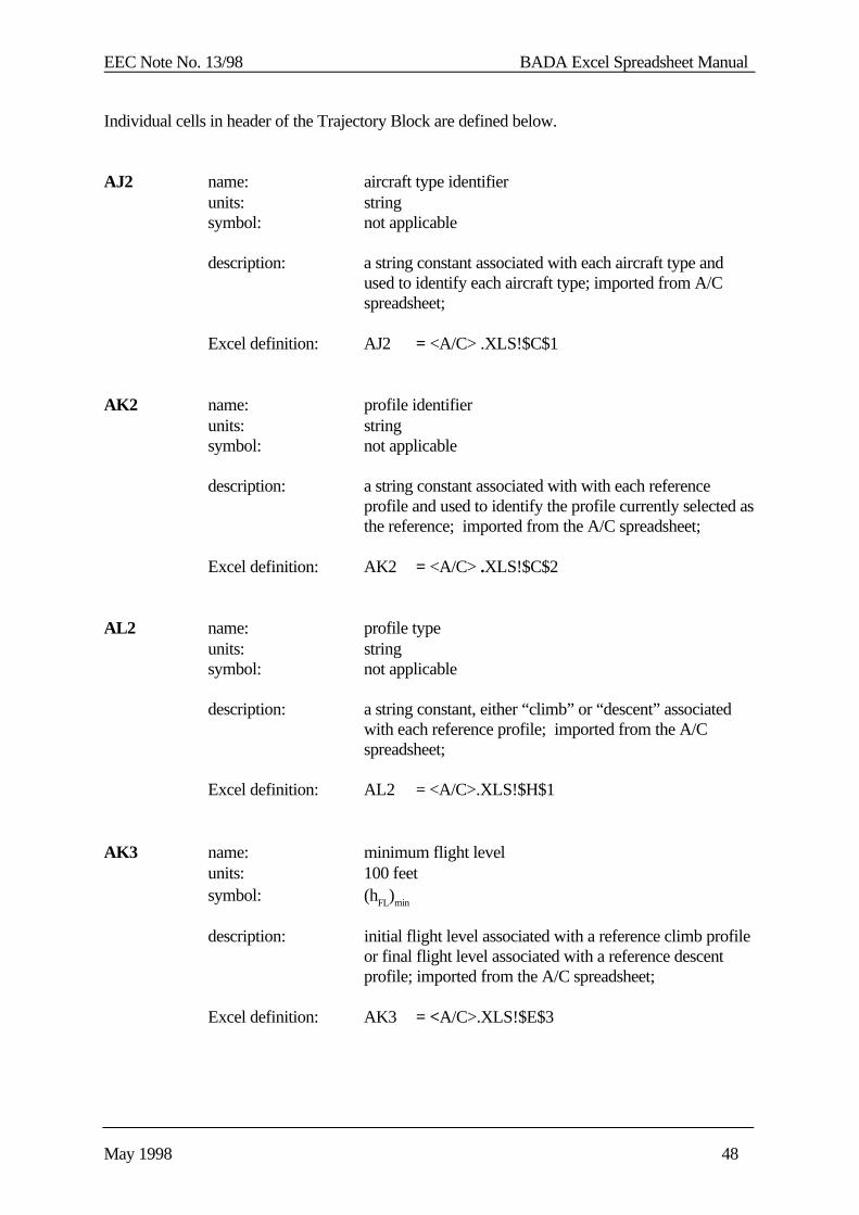
Individual cells in header of the Trajectory Block are defined below.
AJ2 name: aircraft type identifierunits: stringsymbol: not applicable
description: a string constant associated with each aircraft type andused to identify each aircraft type; imported from A/Cspreadsheet;
Excel definition: AJ2 = <A/C> .XLS!$C$1
AK2 name: profile identifierunits: stringsymbol: not applicable
description: a string constant associated with with each referenceprofile and used to identify the profile currently selected asthe reference; imported from the A/C spreadsheet;
Excel definition: AK2 = <A/C> .XLS!$C$2
AL2 name: profile typeunits: stringsymbol: not applicable
description: a string constant, either “climb” or “descent” associatedwith each reference profile; imported from the A/Cspreadsheet;
Excel definition: AL2 = <A/C>.XLS!$H$1
AK3 name: minimum flight levelunits: 100 feetsymbol: (hFL)min
description: initial flight level associated with a reference climb profileor final flight level associated with a reference descentprofile; imported from the A/C spreadsheet;
Excel definition: AK3 = <A/C>.XLS!$E$3
EEC Note No. 13/98 BADA Excel Spreadsheet Manual
May 1998 49
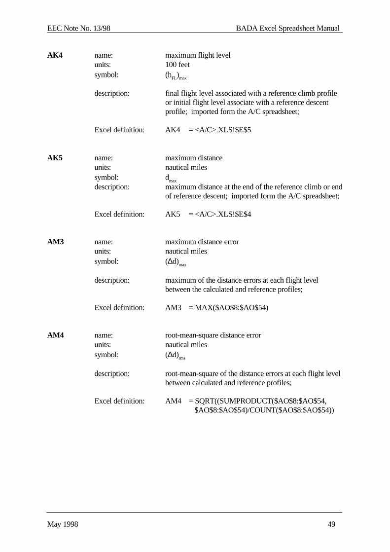
AK4 name: maximum flight levelunits: 100 feetsymbol: (hFL)max
description: final flight level associated with a reference climb profileor initial flight level associate with a reference descentprofile; imported form the A/C spreadsheet;
Excel definition: AK4 = <A/C>.XLS!$E$5
AK5 name: maximum distanceunits: nautical milessymbol: dmax
description: maximum distance at the end of the reference climb or endof reference descent; imported form the A/C spreadsheet;
Excel definition: AK5 = <A/C>.XLS!$E$4
AM3 name: maximum distance errorunits: nautical milessymbol: (∆d)max
description: maximum of the distance errors at each flight level between the calculated and reference profiles;
Excel definition: AM3 = MAX($AO$8:$AO$54)
AM4 name: root-mean-square distance errorunits: nautical milessymbol: (∆d)rms
description: root-mean-square of the distance errors at each flight levelbetween calculated and reference profiles;
Excel definition: AM4 = SQRT((SUMPRODUCT($AO$8:$AO$54, $AO$8:$AO$54)/COUNT($AO$8:$AO$54))
EEC Note No. 13/98 BADA Excel Spreadsheet Manual
May 1998 50
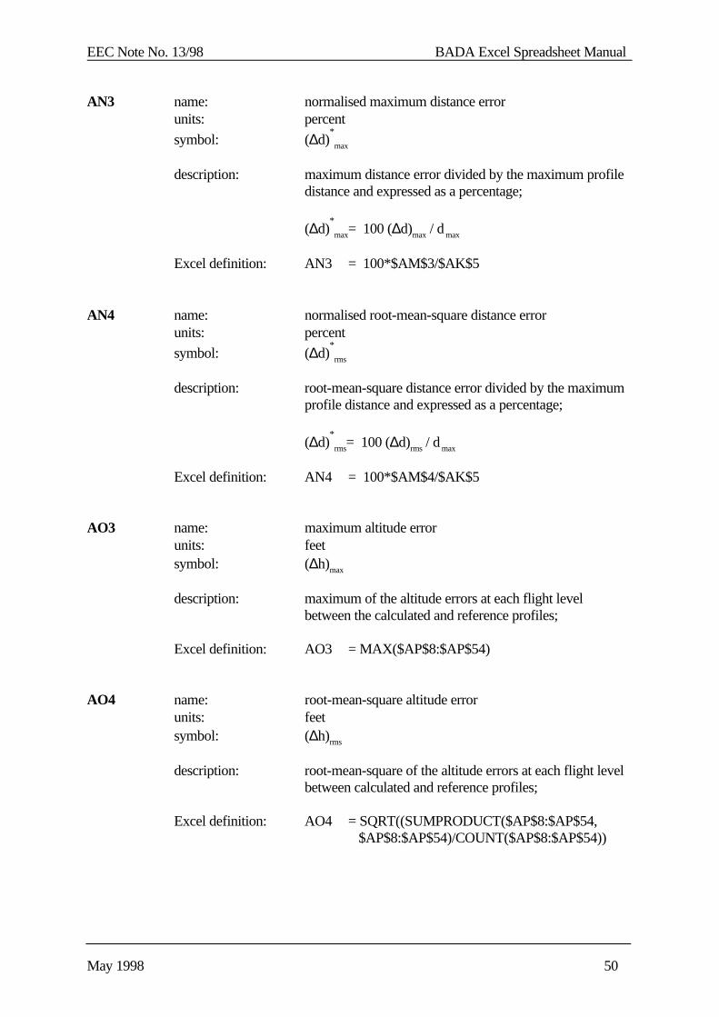
AN3 name: normalised maximum distance errorunits: percent
symbol: (∆d)*
max
description: maximum distance error divided by the maximum profiledistance and expressed as a percentage;
(∆d)*
max= 100 (∆d)max / d max
Excel definition: AN3 = 100*$AM$3/$AK$5
AN4 name: normalised root-mean-square distance errorunits: percent
symbol: (∆d)*
rms
description: root-mean-square distance error divided by the maximumprofile distance and expressed as a percentage;
(∆d)*
rms= 100 (∆d)rms / d max
Excel definition: AN4 = 100*$AM$4/$AK$5
AO3 name: maximum altitude errorunits: feetsymbol: (∆h)max
description: maximum of the altitude errors at each flight level between the calculated and reference profiles;
Excel definition: AO3 = MAX($AP$8:$AP$54)
AO4 name: root-mean-square altitude errorunits: feetsymbol: (∆h)rms
description: root-mean-square of the altitude errors at each flight levelbetween calculated and reference profiles;
Excel definition: AO4 = SQRT((SUMPRODUCT($AP$8:$AP$54, $AP$8:$AP$54)/COUNT($AP$8:$AP$54))
EEC Note No. 13/98 BADA Excel Spreadsheet Manual
May 1998 51
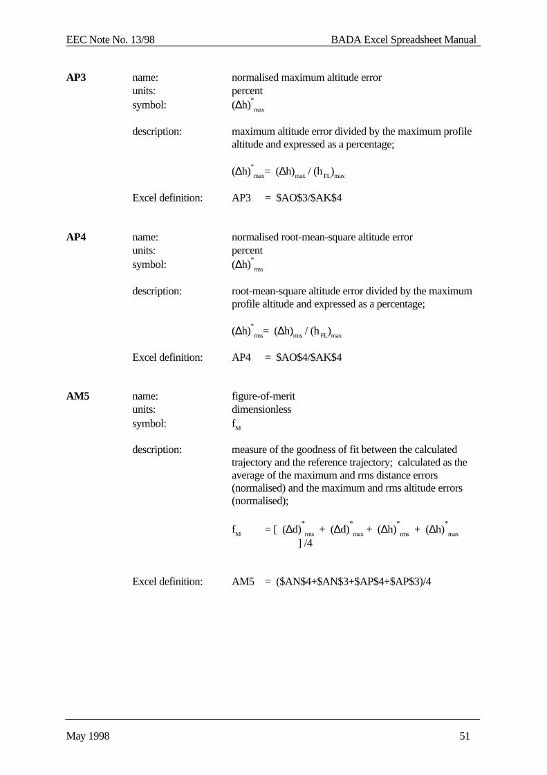
AP3 name: normalised maximum altitude errorunits: percentsymbol: (∆h)
*
max
description: maximum altitude error divided by the maximum profilealtitude and expressed as a percentage;
(∆h)*
max= (∆h)max / (h FL)max
Excel definition: AP3 = $AO$3/$AK$4
AP4 name: normalised root-mean-square altitude errorunits: percentsymbol: (∆h)
*
rms
description: root-mean-square altitude error divided by the maximumprofile altitude and expressed as a percentage;
(∆h)*
rms= (∆h)rms / (h FL)max
Excel definition: AP4 = $AO$4/$AK$4
AM5 name: figure-of-meritunits: dimensionlesssymbol: fM
description: measure of the goodness of fit between the calculatedtrajectory and the reference trajectory; calculated as theaverage of the maximum and rms distance errors(normalised) and the maximum and rms altitude errors(normalised);
fM = [ (∆d)*
rms + (∆d)*
max + (∆h)*
rms + (∆h)*
max ] /4
Excel definition: AM5 = ($AN$4+$AN$3+$AP$4+$AP$3)/4

EEC Note No. 13/98 BADA Excel Spreadsheet Manual
May 1998 52
Columns in the Trajectory Block are defined below
AJ name: flight levelunits: 100 feetsymbol: hFL
description: independent variable for profile calculationvaries from 0 to 450; copied from first column (A)to improve readability of the Trajectory Block
Excel definition: AJ{n} = $A{n}
AK name: allowed flight levelunits: 100 feetsymbol: h FL,allowed
description: same as flight level, but flagged as “not available” forflight levels greater than the maximum flight level of thereference trajectory; this is used as the independentvariable for Excel plots where the “not available” flagresults in the suppression of data points at flight levelsabove the maximum
Excel definition: AK{n} = IF($A{n}>$AK$4, NA( ), $A{n} )
AL name: ground speedunits: knotssymbol: Vx
description: calculated using pythagorean theorem from true air speedand vertical speed; the value is only calculated for flightlevels less than or equal to the maximum flight level of theselected reference profile;
if hFL > (hFL)max
undefinedelse Vx = [VTAS
2 - .000975Vz
2]
0.5
Excel definition: AL{n} = IF($A{n}>$AK$4, “ “, SQRT($K{n}^2-.000975*$AI{n}^2)
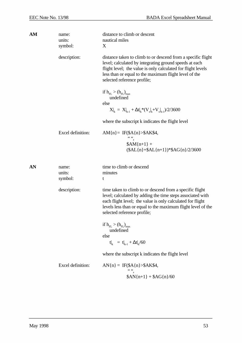
EEC Note No. 13/98 BADA Excel Spreadsheet Manual
May 1998 53
AM name: distance to climb or descentunits: nautical milessymbol: X
description: distance taken to climb to or descend from a specific flightlevel; calculated by integrating ground speeds at eachflight level; the value is only calculated for flight levelsless than or equal to the maximum flight level of theselected reference profile;
if hFL > (hFL)max
undefinedelse X|k = X|k-1 + ∆t|k*(Vx|k+Vx|k-1)/2/3600
where the subscript k indicates the flight level
Excel definition: AM{n}= IF($A{n}>$AK$4, “ “, $AM{n+1} + ($AL{n}+$AL{n+1})*$AG{n}/2/3600
AN name: time to climb or descendunits: minutessymbol: t
description: time taken to climb to or descend from a specific flightlevel; calculated by adding the time steps associated witheach flight level; the value is only calculated for flightlevels less than or equal to the maximum flight level of theselected reference profile;
if hFL > (hFL)max
undefinedelse t|k = t|k-1 + ∆t|k/60
where the subscript k indicates the flight level
Excel definition: AN{n} = IF($A{n}>$AK$4, “ “, $AN{n+1} + $AG{n}/60

EEC Note No. 13/98 BADA Excel Spreadsheet Manual
May 1998 54
AO name: distance error
units: nautical milessymbol: ∆X
description: absolute distance between the calculated time to climb ordescent and the reference profile; the value is onlycalculated for flight levels for which reference distancesare available and if the distance to climb/descent is greaterthan 5% of the distance at the top of climb/descent; thislatter criterion rejects large relative errors that can occur atthe low altitudes
if reference distance not available or X < 0.05dmax
undefinedelse ∆X = | Xref - X |
Excel definition: AO{n} = IF(ISNA(<AC>.XLS!$F{n}), “ “,
IF($AM{n}<0.05*$AK$5 “ “, ABS(<AC> .XLS!$F{n}-$AM{n}))
AP name: equivalent altitude error
units: feetsymbol: ∆h
description: equivalent altitude error at each flight level; calculatedfrom distance error using ratio of ground and verticalspeeds; the value is only calculated for flight levels forwhich distance errors are available;
if ∆X not available undefinedelse ∆h = 60 ∆X (Vz / Vx )
Excel definition: AP{n} = IF($AO{n}=” “, “ “, 60*$AO{n}*$AI{n}/$AL{n} )
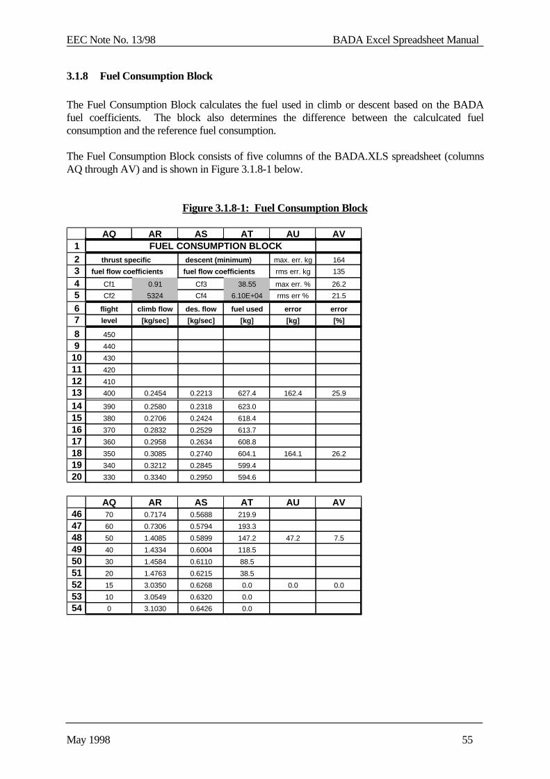
EEC Note No. 13/98 BADA Excel Spreadsheet Manual
May 1998 55
3.1.8 Fuel Consumption Block
The Fuel Consumption Block calculates the fuel used in climb or descent based on the BADAfuel coefficients. The block also determines the difference between the calculcated fuelconsumption and the reference fuel consumption.
The Fuel Consumption Block consists of five columns of the BADA.XLS spreadsheet (columnsAQ through AV) and is shown in Figure 3.1.8-1 below.
Figure 3.1.8-1: Fuel Consumption Block
1234567
89
1011121314151617181920
AQ AR AS AT AU AV FUEL CONSUMPTION BLOCK
thrust specific descent (minimum) max. err. kg 164
fuel flow coefficients fuel flow coefficients rms err. kg 135
Cf1 0.91 Cf3 38.55 max err. % 26.2
Cf2 5324 Cf4 6.10E+04 rms err % 21.5
flight climb flow des. flow fuel used error error
level [kg/sec] [kg/sec] [kg] [kg] [%]
450
440
430
420
410
400 0.2454 0.2213 627.4 162.4 25.9
390 0.2580 0.2318 623.0
380 0.2706 0.2424 618.4
370 0.2832 0.2529 613.7
360 0.2958 0.2634 608.8
350 0.3085 0.2740 604.1 164.1 26.2
340 0.3212 0.2845 599.4
330 0.3340 0.2950 594.6
464748495051525354
AQ AR AS AT AU AV70 0.7174 0.5688 219.9
60 0.7306 0.5794 193.3
50 1.4085 0.5899 147.2 47.2 7.5
40 1.4334 0.6004 118.5
30 1.4584 0.6110 88.5
20 1.4763 0.6215 38.5
15 3.0350 0.6268 0.0 0.0 0.0
10 3.0549 0.6320 0.0
0 3.1030 0.6426 0.0
EEC Note No. 13/98 BADA Excel Spreadsheet Manual
May 1998 56
Individual cells in header of the Fuel Consumption Block are defined below.
AR4 name: first thrust specific fuel consumption coefficientunits: kg/min/kN (jet)
kg/min/kN/knot (turboprop)kg/min (piston)
symbol: Cf1
description: a constant associated with each aircraft type; used tocalculate thrust specific fuel consumption as a function oftrue airspeed; imported from A/C spreadsheet;[RD1, Section 3.9]
Excel definition: AR4 = <A/C>.XLS!$C$32
AR5 name: second thrust specific fuel consumption coefficientunits: knotssymbol: Cf2
description: a constant associated with each aircraft type; used tocalculate thrust specific fuel consumption as a function oftrue airspeed; imported from A/C spreadsheet;[RD1, Section 3.9]
Excel definition: AR5 = <A/C>.XLS!$C$33
AT4 name: first minimum fuel flow coefficientunits: kg/minsymbol: Cf3
description: a constant associated with each aircraft type; used tocalculate minimum fuel flow as a function of altitude;imported from A/C spreadsheet;[RD1, Section 3.9]
Excel definition: AT4 = <A/C>.XLS!$C$34

EEC Note No. 13/98 BADA Excel Spreadsheet Manual
May 1998 57
AT5 name: second thrust specific fuel consumption coefficientsunits: feetsymbol: Cf4
description: a constant associated with each aircraft type; used tocalculate minimum fuel flow as a function of altitude;imported from A/C spreadsheet;[RD1, Section 3.9]
Excel definition: AT5 = <A/C>.XLS!$C$35
AV2 name: maximum fuel consumption errorunits: kgsymbol: (∆w)max
description: maximum error between calculated fuel consumption andreference fuel consumption
Excel definition: AV2 = MAX($AU$8:$AU$54)
AV3 name: root-mean-square fuel consumption errorunits: kgsymbol: (∆w)rms
description: root-mean-square error between calculated fuelconsumption and reference fuel consumption
Excel definition: AV3 = SQRT(SUMPRODUCT($AU$8:$AU$54, $AU$8:$AU$54)/COUNT($AU$8:$AU$54))
AV4 name: normalized maximum fuel consumption errorunits: percent
symbol: (∆w)*
max
description: maximum of normalized error between calculated fuelconsumption and reference fuel consumption
Excel definition: AV4 = MAX($AV$8:$AV$54)
EEC Note No. 13/98 BADA Excel Spreadsheet Manual
May 1998 58
AV5 name: normalized root-mean-square fuel consumption errorunits: percent
symbol: (∆w)*
rms
description: root-mean-square of normalized error between calculatedfuel consumption and reference fuel consumption
Excel definition: AV5 = SQRT(SUMPRODUCT($AV$8:$AV$54, $AV$8:$AV$54)/COUNT($AV$8:$AV$54))
Columns in the Fuel Consumption Block are defined below
AQ name: flight levelunits: 100 feetsymbol: hFL
description: independent variable for profile calculationvaries from 0 to 450; copied from first column (A)to improve readability of the Fuel Consumption Block
Excel definition: AQ{n} = $A{n}
AR name: climb fuel flowunits: kg/secsymbol: fcl
description: fuel flow during climb trajectory, calculated as product ofthrust times the thrust specific fuel consumption;[RD1, Section 3.9]the value is only calculated for flight levels less than orequal to the maximum flight level of the selected referenceprofile
if hFL > (hFL)max then fcl is undefinedelse if engine type is jet then fcl = Cf1 (1+VTAS/Cf2 )T/ 60 else if engine type is turboprop then fcl = Cf1 (1-VTAS/Cf2 ) T (VTAS/1000) /60 else engine type is piston then fcl = Cf1 /60
EEC Note No. 13/98 BADA Excel Spreadsheet Manual
May 1998 59
Excel definition: AR{n} = IF($A{n}>$AK$4, “ “, IF($T$2 = “jet”
$AR$4*(1+$K{n}/$AR$5)*$Y{n}/60, IF$T$2 = “turbo”, $AR$4*(1-$K{n}/$AR$5)
*$Y{n}*($K{n}/1000)/60, $AR$4 / 60 ) ) )
AS name: descent fuel flowunits: kg/secsymbol: fdes
description: fuel flow during descent trajectory calculated the same asminimum fuel flow;[RD1, Section 3.9]the value is only calculated for flight levels less than orequal to the maximum flight level of the selected referenceprofile
if hFL > (hFL)max then fcl is undefinedelse if engine type is jet or turboprop then fcl = Cf3 (1-100hFL/Cf4 ) / 60 else engine type is piston then fcl = Cf4 /60
Excel definition: AS{n} = IF($A{n}>$AK$4, “ “, IF($T$2 = “jet”
$AT$4*(1-$A{n}/$AT$5)/60, IF$T$2 = “turbo”, $AT$4*(1-$A{n}/$AT$5)/60,
$AT$4 / 60 ) ) )
AT name: fuel to climb or descentunits: kgsymbol: w
description: fuel needed to climb to or descend from a specific flightlevel; calculated by integrating either the climb fuel flowor descent fuel flow as appropriate; for flight levels lessthan the minimum flight level the fuel needed is set tozero; the value is only calculated for flight levels less thanor equal to the maximum flight level of the selectedreference profile
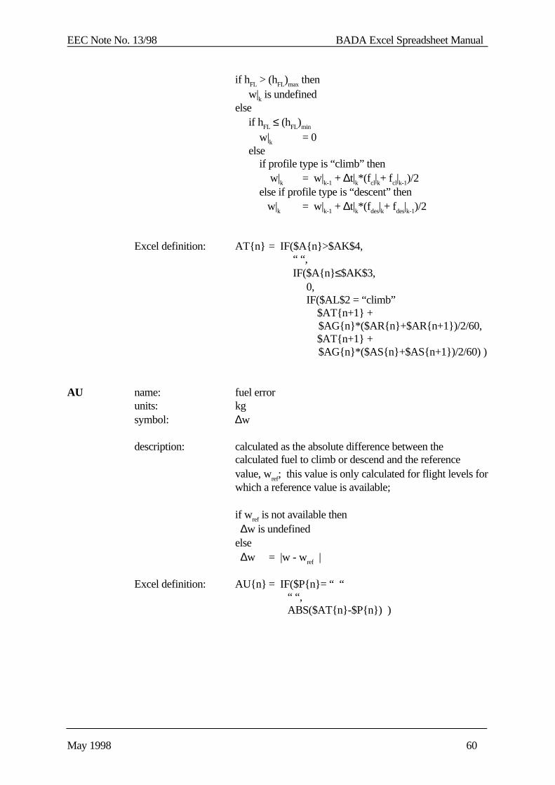
EEC Note No. 13/98 BADA Excel Spreadsheet Manual
May 1998 60
if hFL > (hFL)max then w|k is undefinedelse if hFL ≤ (hFL)min
w|k = 0 else if profile type is “climb” then w|k = w|k-1 + ∆t|k*(f cl|k+ fcl|k-1)/2 else if profile type is “descent” then w|k = w|k-1 + ∆t|k*(f des|k+ fdes|k-1)/2
Excel definition: AT{n} = IF($A{n}>$AK$4, “ “, IF($A{n}≤$AK$3, 0, IF($AL$2 = “climb” $AT{n+1} +
$AG{n}*($AR{n}+$AR{n+1})/2/60, $AT{n+1} +
$AG{n}*($AS{n}+$AS{n+1})/2/60) )
AU name: fuel errorunits: kgsymbol: ∆w
description: calculated as the absolute difference between thecalculated fuel to climb or descend and the referencevalue, wref; this value is only calculated for flight levels forwhich a reference value is available;
if w ref is not available then ∆w is undefinedelse ∆w = |w - wref |
Excel definition: AU{n} = IF($P{n}= “ “ “ “, ABS($AT{n}-$P{n}) )
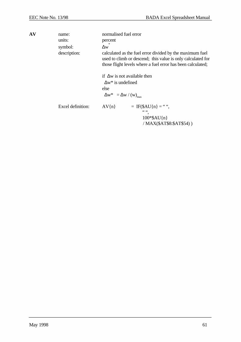
EEC Note No. 13/98 BADA Excel Spreadsheet Manual
May 1998 61
AV name: normalised fuel errorunits: percent
symbol: ∆w*
description: calculated as the fuel error divided by the maximum fuelused to climb or descend; this value is only calculated forthose flight levels where a fuel error has been calculated;
if ∆w is not available then ∆w* is undefinedelse ∆w* = ∆w / (w)max
Excel definition: AV{n} = IF($AU{n} = “ “, “ “, 100*$AU{n}
/ MAX($AT$8:$AT$54) )
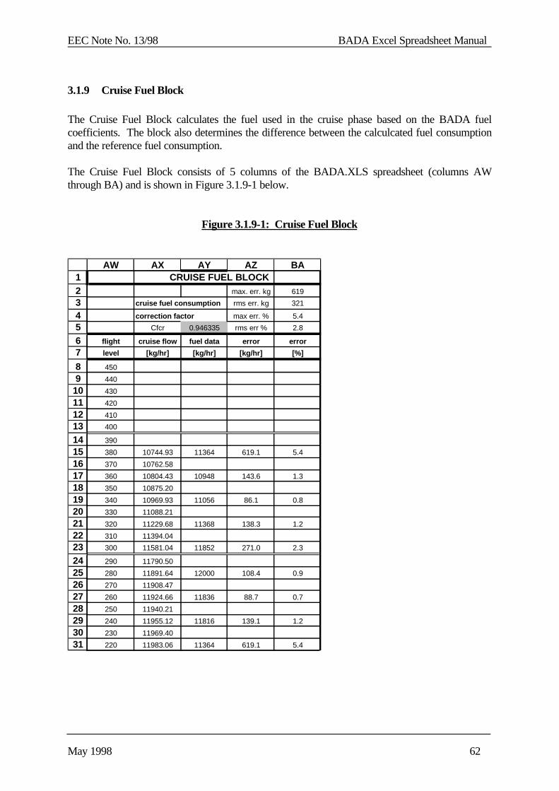
EEC Note No. 13/98 BADA Excel Spreadsheet Manual
May 1998 62
3.1.9 Cruise Fuel Block
The Cruise Fuel Block calculates the fuel used in the cruise phase based on the BADA fuelcoefficients. The block also determines the difference between the calculcated fuel consumptionand the reference fuel consumption.
The Cruise Fuel Block consists of 5 columns of the BADA.XLS spreadsheet (columns AWthrough BA) and is shown in Figure 3.1.9-1 below.
Figure 3.1.9-1: Cruise Fuel Block
1234567
89
10111213141516171819202122232425262728293031
AW AX AY AZ BA CRUISE FUEL BLOCK
max. err. kg 619
cruise fuel consumption rms err. kg 321
correction factor max err. % 5.4
Cfcr 0.946335 rms err % 2.8
flight cruise flow fuel data error error
level [kg/hr] [kg/hr] [kg/hr] [%]
450
440
430
420
410
400
390
380 10744.93 11364 619.1 5.4
370 10762.58
360 10804.43 10948 143.6 1.3
350 10875.20
340 10969.93 11056 86.1 0.8
330 11088.21
320 11229.68 11368 138.3 1.2
310 11394.04
300 11581.04 11852 271.0 2.3
290 11790.50
280 11891.64 12000 108.4 0.9
270 11908.47
260 11924.66 11836 88.7 0.7
250 11940.21
240 11955.12 11816 139.1 1.2
230 11969.40
220 11983.06 11364 619.1 5.4
EEC Note No. 13/98 BADA Excel Spreadsheet Manual
May 1998 63
Note that the data in the Cruise Fuel Block is only relevant when a Cruise Trajectory (e.g. CRZ1)has been selected in the <A/C>.XLS. Furthermore the cruise data below 10,000 ft is usually notentered in the <A/C>.XLS, so all data below 10,000 ft is ignored.
Individual cells in header of the Fuel Consumption Block are defined below.
AY5 name: cruise fuel flow factorunits: dimensionlesssymbol: Cfcr
description: factor used as a correction to the thrust specific fuelconsumption in order to calculate the cruise fuel flow[RD1, Section 3.9]
Excel definition: AY5 = <A/C>.XLS!$C$60
BA2 name: maximum cruise fuel consumption errorunits: kgsymbol: (∆w)max
description: maximum error between calculated cruise fuelconsumption and reference cruise fuel consumption
Excel definition: BA2 = MAX($AZ$8:$AZ$53)
BA3 name: root-mean-square cruise fuel consumption errorunits: kgsymbol: (∆w)rms
description: root-mean-square error between calculated cruise fuelconsumption and reference cruise fuel consumption
Excel definition: BA3 = SQRT(SUMPRODUCT($AZ$8:$AZ$53, $AZ$8:$AZ$53)/COUNT($AZ$8:$AZ$53))

EEC Note No. 13/98 BADA Excel Spreadsheet Manual
May 1998 64
BA4 name: normalized maximum cruise fuel consumption errorunits: percent
symbol: (∆w)*
max
description: maximum of normalized error between calculated cruisefuel consumption and reference cruise fuel consumption
Excel definition: BA4 = MAX($BA$8:$BA$53)
BA5 name: normalized root-mean-square cruise fuel consumptionerror
units: percent
symbol: (∆w)*
rms
description: root-mean-square of normalized error between calculatedcruise fuel consumption and reference cruise fuelconsumption
Excel definition: BA5 = SQRT(SUMPRODUCT($BA$8:$BA$53, $BA$8:$BA$53)/COUNT($BA$8:$BA$53))
Columns in the Cruise Fuel Block are defined below
AW name: flight levelunits: 100 feetsymbol: hFL
description: independent variable for profile calculationvaries from 0 to 450; copied from first column (A)to improve readability of the Fuel Consumption Block
Excel definition: AW{n}= $A{n}
AX name: cruise fuel flowunits: kg/hrsymbol: fcr
description: fuel flow during cruise, calculated as product of thrusttimes the thrust specific fuel consumption time the cruisefuel flow factor[RD1, Section 3.9]the value is only calculated for flight levels less than orequal to the maximum flight level of the selected referenceprofile
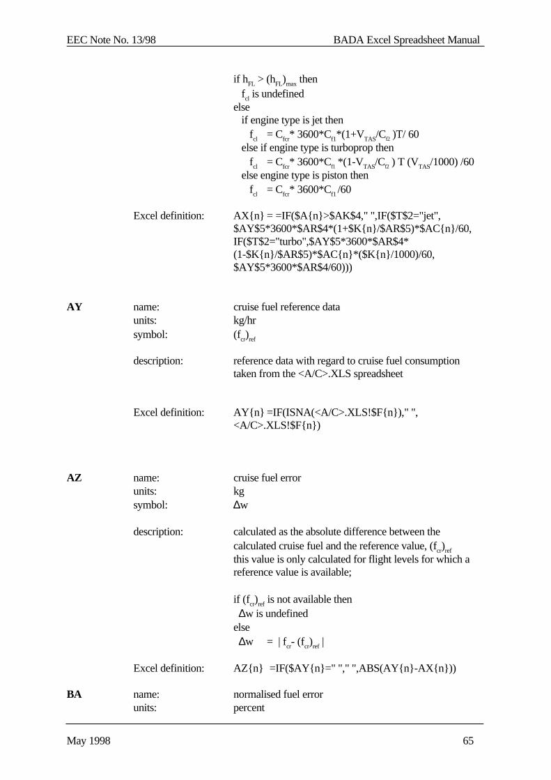
EEC Note No. 13/98 BADA Excel Spreadsheet Manual
May 1998 65
if hFL > (hFL)max then fcl is undefinedelse if engine type is jet then fcl = Cfcr* 3600*Cf1*(1+VTAS/Cf2 )T/ 60 else if engine type is turboprop then fcl = Cfcr* 3600*Cf1 *(1-VTAS/Cf2 ) T (VTAS/1000) /60 else engine type is piston then fcl = Cfcr* 3600*Cf1 /60
Excel definition: AX{n} = =IF($A{n}>$AK$4," ",IF($T$2="jet",$AY$5*3600*$AR$4*(1+$K{n}/$AR$5)*$AC{n}/60,IF($T$2="turbo",$AY$5*3600*$AR$4*(1-$K{n}/$AR$5)*$AC{n}*($K{n}/1000)/60,$AY$5*3600*$AR$4/60)))
AY name: cruise fuel reference dataunits: kg/hrsymbol: (fcr)ref
description: reference data with regard to cruise fuel consumptiontaken from the <A/C>.XLS spreadsheet
Excel definition: AY{n} =IF(ISNA(<A/C>.XLS!$F{n})," ",<A/C>.XLS!$F{n})
AZ name: cruise fuel errorunits: kgsymbol: ∆w
description: calculated as the absolute difference between thecalculated cruise fuel and the reference value, (fcr)ref
this value is only calculated for flight levels for which areference value is available;
if (fcr)ref is not available then ∆w is undefinedelse ∆w = | fcr- (fcr)ref |
Excel definition: AZ{n} =IF($AY{n}=" "," ",ABS(AY{n}-AX{n}))
BA name: normalised fuel errorunits: percent
EEC Note No. 13/98 BADA Excel Spreadsheet Manual
May 1998 66
symbol: ∆w*
description: calculated as the fuel error divided by the maximum cruisefuel; this value is only calculated for those flight levelswhere a fuel error has been calculated;
if ∆w is not available then ∆w* is undefinedelse ∆w* = ∆w / (fcr)max
Excel definition: BA{n} = IF($AY{n}=" "," ",ABS((($AX{n}-$AY{n})/$AY{n})*100))

EEC Note No. 13/98 BADA Excel Spreadsheet Manual
May 1998 67
3.2 <A/C>.XLS
The purpose of the <A/C>.XLS spreadsheet is to store all the reference information and BADAcoefficients that are associated with a specific aircraft type.
The name of each spreadsheet is based on the ICAO code of the aircraft type. Thus, thespreadsheet for the Boeing 737-300 is named B73S.XLS. Similarly, the spreadsheet for theMcDonnell-Douglas DC-9 is named DC9.XLS. Note that most of the <A/C>.XLS files werecreated using the old ICAO designator standard. Each <A/C>.XLS spreadsheet has the samestructure, consisting of a BADA Coefficient Block, a Selected Trajectory Block and a variablenumber of Reference Trajectories Block. Each block is 54 rows in length. This organisation isshown in Figure 3.2.0-1 below.
Figure 3.2.0-1: Organisation of <A/C>.XLS Spreadsheet
BADACoefficientBlock
SelectedTrajectoryBlock
ReferenceTrajectoryClimb/DesBlockNumber 1
ReferenceTrajectoryClimb/DesBlockNumber 2
... ... ...
ReferenceTrajectoryClimb/DesBlockNumber N
ReferenceTrajectoryCruiseBlockNumber 1
The BADA Coefficient Block contains all BADA coefficients that are to be placed in the OPFand APF files. Some of these coefficients such as reference surface area (S) and maximumoperating altitude (hMO) are determined from reference manuals. Other coefficients such as thedrag coefficients (CD0 and CD2 ) need to be calculated as described in Section 4.
The BADA.XLS spreadsheet imports the coefficient values from the BADA Coefficient Blockwhen calculating climb and descent trajectories. Each of the Reference Trajectory Blocksspecifies a climb or descent trajectory in terms of distance, time and fuel needed to climb to ordescent from a flight level, or a provides cruise fuel flow data as a function of altitude (always thelast block). Values for flight levels from 450 to 0 are placed in rows 8 to 54, compatible with theBADA.XLS spreadsheet. Each of the reference trajectories represents different conditions interms of climb/descent, aircraft mass, speed or temperature deviation from ISA. Each of thereference trajectories is given an identifier (eg. CL1, CL2, DES1, CRZ1) to distinguish it from theother trajectories. Note that the cruise trajectory (CRZx) has a different format and will bedescribed seperately.
The Selected Trajectory Block is similar in structure to a Reference Trajectory Block. It is usedas a working area and contains the values corresponding to the reference trajectory which iscurrently selected as a basis for calculations. The BADA.XLS spreadsheet, as well as theTRAJECT.XLS, FUEL_CRZ.XLS, ROCD.XLS and FUEL.XLS charts import the referencetrajectory specifications from the Selected Trajectory Block.
Further information on all of the four types of blocks in the <A/C>.XLS spreadsheet are given inthe subsections below.

EEC Note No. 13/98 BADA Excel Spreadsheet Manual
May 1998 68
3.2.1 BADA Coefficient Block
The BADA Coefficient Block contains all BADA coefficients that are to be placed in theOperations Performance File (OPF) and (Airline Performance File) APF files. This blockconsists of three columns, A through C, of each <A/C>.XLS spreadsheet and is shown in Figure3.2.1-1.
All coefficient values are placed in row C with labels placed in rows A and B. All values that areto be entered by the user are shaded in light blue. This comprises all values except the minimumdrag speed, which is automatically calculated from the mass and drag coefficients.
The values in row C can be divided into the following categories:
(a) Input from A/C Reference Manuals
These are values such as aircraft mass and stall speeds, which are looked up inA/C reference manuals or Jane’s and entered directly into the spreadsheet. Oncethese values are entered they need not be changed. A special case of this type iscell C1, which specifies the aircraft identifier. This corresponds to the ICAOidentifier for the aircraft type and must be the same as the name of thespreadsheet, for example, B727 for the B727.XLS spreadsheet. Some input is notdirectly available but needs to be extracted from data in the Flight Manual.Expamples are the maximum dynamic altitude parameters. These parameters arenot directly available but need to be determined using maximum altitude graphs.
(b) Optimised Coefficients
These are values that are calculated in order to obtain the best match betweenBADA calculated trajectories and the reference trajectories. This includes thedrag coefficients, thrust coefficients and fuel flow coefficients.
(c) Automatic Calculation Parameters
There is only on value of this type. This is the minimum drag speed in cell C14which is automatically calculated as a function of the mass and drag coefficients.
(d) Profile Selection Parameter
There is only one value of this type. This is the profile identifier in cell C2. Thiscell can be set to any one of the profile identifiers associated with a ReferenceTrajectory Block in the spreadsheet. This causes the Selected Trajectory Block tobe updated to contain the selected profile data.
A detailed description of each of the coefficients in the block is given in Table 3.2.1-1.

EEC Note No. 13/98 BADA Excel Spreadsheet Manual
May 1998 69
Figure 3.2.1-1 : Coefficient Block
123456789
1011121314151617181920212223242526272829303132333435363738394041424344454647484950515253
A B C
Aircraft Type B747
Selected Trajectory DES1
A/C m(ref) 280
mass m(max) 380
m(min) 173.0
m(payload) 64.6
speed Vmo 375
limits Mmo 0.92
ceiling hmo 45100
drag S 512
coeff. CD0 0.0185
CD2 0.0656
CM16 0
min drag speed 249
engine type jet
number 4
climb C Tc,1 568288
thrust C Tc,2 59488
coeff. C Tc,3 0.00E+00
temp. C Tc,4 1.6100
coeff C Tc,5 0.0027
reduced power [y/n] n
cruise C Tcr 0.95
descent C Tdes,lo 0.0900
thrust C Tdes,hi 0.0800
coeff. hdes 20000
reference V des,ref 300
descent Mdes,ref 0.84
TSFC Cf1 0.9068
Cf2 5324
minimum Cf3 38.5540
fuel flow Cf4 61014
stall (Vstall)CR 179
speeds (Vstall)IC 132
(Vstall)TO 130
(Vstall)AP 130
(Vstall)LD 120
spd.sched.[law/stall] law
nominal V cl,1 340
climb V cl,2 340
speeds M cl 0.82
nominal V cr,1 340
cruise V cr,2 340
speeds M cr 0.82
nominal V des,1 300
descent V des,2 300
speeds M des 0.84
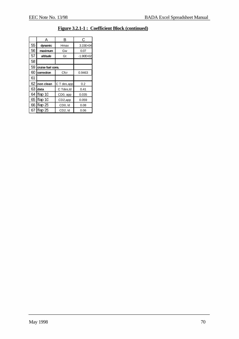
EEC Note No. 13/98 BADA Excel Spreadsheet Manual
May 1998 70
Figure 3.2.1-1 : Coefficient Block (continued)
55565758596061626364656667
A B Cdynamic Hmax 3.15E+04
maximum Gw 0.07
altitude Gt -1.90E+02
cruise fuel cons.
correction Cfcr 0.9463
non clean C T des,app 0.2
data C Tdes,ld 0.41
flap 10 CD0, app 0.035
flap 10 CD2,app 0.059
flap 25 CD0, ld 0.08
flap 25 CD2, ld 0.06
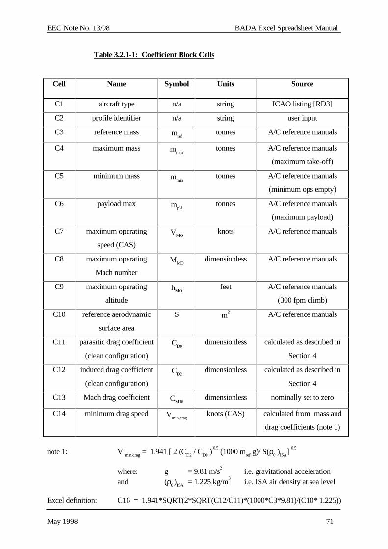
EEC Note No. 13/98 BADA Excel Spreadsheet Manual
May 1998 71
Table 3.2.1-1: Coefficient Block Cells
Cell Name Symbol Units Source
C1 aircraft type n/a string ICAO listing [RD3]
C2 profile identifier n/a string user input
C3 reference mass mreftonnes A/C reference manuals
C4 maximum mass mmaxtonnes A/C reference manuals
(maximum take-off)
C5 minimum mass mmintonnes A/C reference manuals
(minimum ops empty)
C6 payload max mpldtonnes A/C reference manuals
(maximum payload)
C7 maximum operating
speed (CAS)
VMOknots A/C reference manuals
C8 maximum operating
Mach number
MMOdimensionless A/C reference manuals
C9 maximum operating
altitude
hMOfeet A/C reference manuals
(300 fpm climb)
C10 reference aerodynamic
surface area
S m2 A/C reference manuals
C11 parasitic drag coefficient
(clean configuration)
CD0dimensionless calculated as described in
Section 4
C12 induced drag coefficient
(clean configuration)
CD2dimensionless calculated as described in
Section 4
C13 Mach drag coefficient CM16dimensionless nominally set to zero
C14 minimum drag speed Vmin,dragknots (CAS) calculated from mass and
drag coefficients (note 1)
note 1: V min,drag = 1.941 [ 2 (CD2 / CD0 ) 0.5
(1000 mref g)/ S(ρ0 )ISA] 0.5
where: g = 9.81 m/s2 i.e. gravitational acceleration
and (ρ0 )ISA = 1.225 kg/m3
i.e. ISA air density at sea level
Excel definition: C16 = 1.941*SQRT(2*SQRT(C12/C11)*(1000*C3*9.81)/(C10* 1.225))

EEC Note No. 13/98 BADA Excel Spreadsheet Manual
May 1998 72
Table 3.2.1-1: Coefficient Block Cells (continued)
Cell Name Symbol Units Source
C16 engine type n/a “jet”, “turbo” or
“piston”
A/C reference manuals
C17 number of engines nengdimensionless A/C reference manuals
C19 1st maximum climb
thrust coefficient
C Tc,1N (jet/turbo)
knot-N (piston)
calculated as described in
Section 4
C20 2nd maximum climb
thrust coefficient
C Tc,2feet calculated as described in
Section 4
C21 3rd maximum climb
thrust coefficient
C Tc,3 1/ft2 (jet)
N (turbo)
knot-N (piston)
calculated as described in
Section 4
C22 1st thrust temperature
coefficient
C Tc,4deg. C calculated as described in
Section 4
C23 2nd thrust temperature
coefficient
C Tc,5dimensionless calculated as described in
Section 4
C25 cruise thrust coefficient C Tcrdimensionless set to 0.95
C26 low altitude descent
thrust coefficient
C Tdes,lodimensionless calculated as described in
Section 4
C27 high altitude descent
thrust coefficient
C Tdes,hidimensionless calculated as described in
Section 4
C28 descent thrust transition
altitude
h desfeet calculated as described in
Section 4
C29 reference descent speed Vdes,refknots (CAS) calculated as described in
Section 4
C30 reference descent Mach
number
Mdes,refdimensionless calculated as described in
Section 4
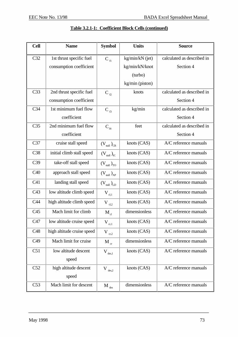
EEC Note No. 13/98 BADA Excel Spreadsheet Manual
May 1998 73
Table 3.2.1-1: Coefficient Block Cells (continued)
Cell Name Symbol Units Source
C32 1st thrust specific fuel
consumption coefficient
C f1 kg/min/kN (jet)
kg/min/kN/knot
(turbo)
kg/min (piston)
calculated as described in
Section 4
C33 2nd thrust specific fuel
consumption coefficient
C f2 knots calculated as described in
Section 4
C34 1st minimum fuel flow
coefficient
C f3 kg/min calculated as described in
Section 4
C35 2nd minimum fuel flow
coefficient
C f4feet calculated as described in
Section 4
C37 cruise stall speed (Vstall )CRknots (CAS) A/C reference manuals
C38 initial climb stall speed (Vstall )ICknots (CAS) A/C reference manuals
C39 take-off stall speed (Vstall )TOknots (CAS) A/C reference manuals
C40 approach stall speed (Vstall )APknots (CAS) A/C reference manuals
C41 landing stall speed (Vstall )LDknots (CAS) A/C reference manuals
C43 low altitude climb speed V cl,1knots (CAS) A/C reference manuals
C44 high altitude climb speed V cl,2knots (CAS) A/C reference manuals
C45 Mach limit for climb M cldimensionless A/C reference manuals
C47 low altitude cruise speed V cr,1knots (CAS) A/C reference manuals
C48 high altitude cruise speed V cr,2knots (CAS) A/C reference manuals
C49 Mach limit for cruise M crdimensionless A/C reference manuals
C51 low altitude descent
speed
V des,1knots (CAS) A/C reference manuals
C52 high altitude descent
speed
V des,2knots (CAS) A/C reference manuals
C53 Mach limit for descent M desdimensionless A/C reference manuals
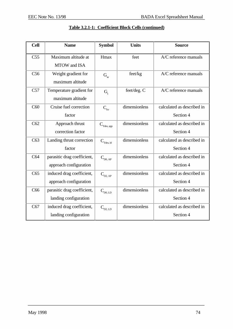
EEC Note No. 13/98 BADA Excel Spreadsheet Manual
May 1998 74
Table 3.2.1-1: Coefficient Block Cells (continued)
Cell Name Symbol Units Source
C55 Maximum altitude at
MTOW and ISA
Hmax feet A/C reference manuals
C56 Weight gradient for
maximum altitude
Gwfeet/kg A/C reference manuals
C57 Temperature gradient for
maximum altitude
Gtfeet/deg. C A/C reference manuals
C60 Cruise fuel correction
factor
Cfcrdimensionless calculated as described in
Section 4
C62 Approach thrust
correction factor
CTdes, appdimensionless calculated as described in
Section 4
C63 Landing thrust correction
factor
CTdes, lddimensionless calculated as described in
Section 4
C64 parasitic drag coefficient,
approach configuration
CD0, APdimensionless calculated as described in
Section 4
C65 induced drag coefficient,
approach configuration
CD2, APdimensionless calculated as described in
Section 4
C66 parasitic drag coefficient,
landing configuration
CD0, LDdimensionless calculated as described in
Section 4
C67 induced drag coefficient,
landing configuration
CD2, LDdimensionless calculated as described in
Section 4

EEC Note No. 13/98 BADA Excel Spreadsheet Manual
May 1998 75
3.2.2 Selected Trajectory Block
The Selected Trajectory Block holds the data corresponding to the selected reference trajectory. The data is copied from the particularly Reference Trajectory Block that corresponds to the profileselected by the user in cell C2. This allows for the BADA.XLS spreadsheet and the charts to havea constant link point when importing reference profile information.
The Selected Trajectory Block consists of five columns of the <A/C>.XLS spreadsheet (columnsD through I) and is shown in Figure 3.2.2-1 below. Rows 1 through 7 contain header informationthat applies globally to the profile. Rows 8 through 54 contain distance, time, fuel and ROCDdata as a function of flight level.
Figure 3.2.2-1: Selected Trajectory Block
123456789
101112131415161718
D E F G H I
selected trajectory CL1 climb
delta T 0.00 C
min FL: 15 mass 190.00 tonnes
max dist: 114 max spd KCAS 310 310
max FL: 440 0.820 Mach
REF. FLIGHT DIST TIME FUEL ROCD
LEVEL LEVEL [n. miles] [min] [kg] [fpm]
450 #N/A #N/A #N/A #N/A
440 440 114.00 16.00 4500.00 #N/A
430 #N/A #N/A #N/A #N/A
420 420 97.00 13.00 4150.00 #N/A
410 #N/A #N/A #N/A #N/A
400 400 84.00 12.00 3850.00 #N/A
390 #N/A #N/A #N/A #N/A
380 380 75.00 11.00 3600.00 #N/A
370 #N/A #N/A #N/A #N/A
360 360 67.00 10.00 3400.00 #N/A
350 #N/A #N/A #N/A #N/A
464748495051525354
D E F G H I 70 #N/A #N/A #N/A #N/A
60 #N/A #N/A #N/A #N/A
50 #N/A #N/A #N/A #N/A
40 #N/A #N/A #N/A #N/A
30 #N/A #N/A #N/A #N/A
20 #N/A #N/A #N/A #N/A
15 15 0.00 0.00 0.00 #N/A
10 #N/A #N/A #N/A #N/A
0 #N/A #N/A #N/A #N/A
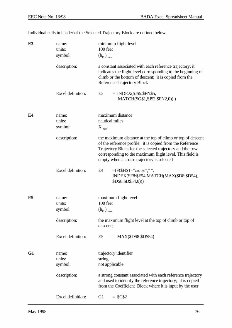
EEC Note No. 13/98 BADA Excel Spreadsheet Manual
May 1998 76
Individual cells in header of the Selected Trajectory Block are defined below.
E3 name: minimum flight levelunits: 100 feetsymbol: (hFL) min
description: a constant associated with each reference trajectory; itindicates the flight level corresponding to the beginning ofclimb or the bottom of descent; it is copied from theReference Trajectory Block
Excel definition: E3 = INDEX($J$5:$FN$5, MATCH($G$1,$J$2:$FN2,0)) )
E4 name: maximum distanceunits: nautical milessymbol: X max
description: the maximum distance at the top of climb or top of descentof the reference profile; it is copied from the ReferenceTrajectory Block for the selected trajectory and the rowcorresponding to the maximum flight level. This field isempty when a cruise trajectory is selected
Excel definition: E4 =IF($H$1="cruise"," ",INDEX($F8:$F54,MATCH(MAX($D8:$D54),$D$8:$D$54,0)))
E5 name: maximum flight levelunits: 100 feetsymbol: (hFL) max
description: the maximum flight level at the top of climb or top ofdescent;
Excel definition: E5 = MAX($D$8:$D$54)
G1 name: trajectory identifierunits: stringsymbol: not applicable
description: a strong constant associated with each reference trajectoryand used to identify the reference trajectory; it is copiedfrom the Coefficient Block where it is input by the user
Excel definition: G1 = $C$2
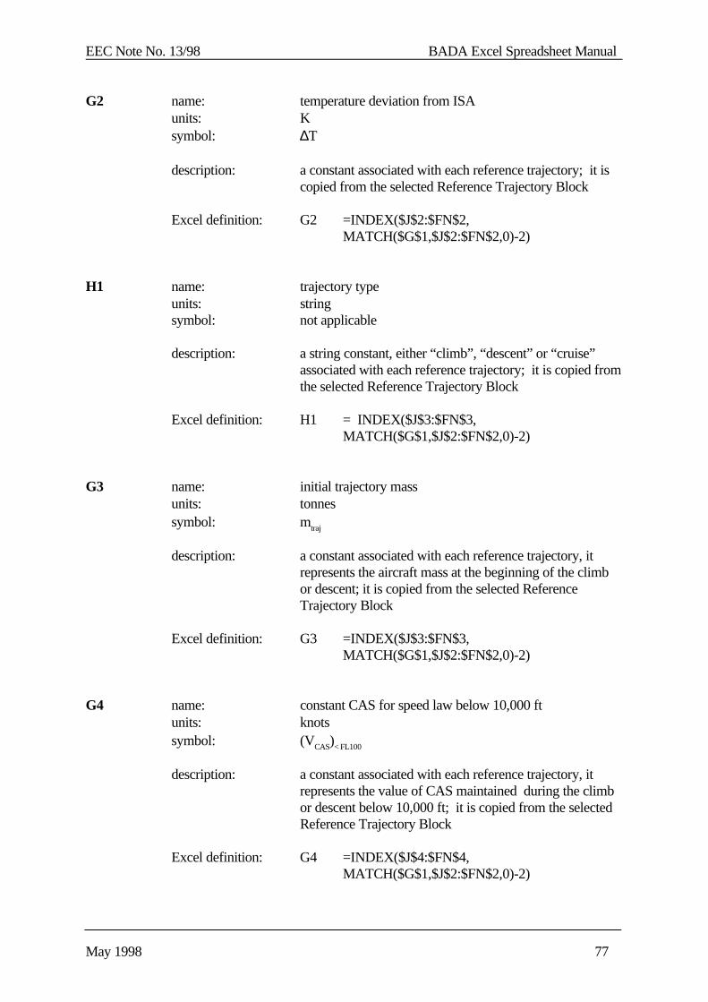
EEC Note No. 13/98 BADA Excel Spreadsheet Manual
May 1998 77
G2 name: temperature deviation from ISAunits: Ksymbol: ∆T
description: a constant associated with each reference trajectory; it iscopied from the selected Reference Trajectory Block
Excel definition: G2 =INDEX($J$2:$FN$2,MATCH($G$1,$J$2:$FN$2,0)-2)
H1 name: trajectory typeunits: stringsymbol: not applicable
description: a string constant, either “climb”, “descent” or “cruise”associated with each reference trajectory; it is copied fromthe selected Reference Trajectory Block
Excel definition: H1 = INDEX($J$3:$FN$3,MATCH($G$1,$J$2:$FN$2,0)-2)
G3 name: initial trajectory massunits: tonnessymbol: mtraj
description: a constant associated with each reference trajectory, itrepresents the aircraft mass at the beginning of the climbor descent; it is copied from the selected ReferenceTrajectory Block
Excel definition: G3 =INDEX($J$3:$FN$3,MATCH($G$1,$J$2:$FN$2,0)-2)
G4 name: constant CAS for speed law below 10,000 ftunits: knotssymbol: (VCAS)< FL100
description: a constant associated with each reference trajectory, itrepresents the value of CAS maintained during the climbor descent below 10,000 ft; it is copied from the selectedReference Trajectory Block
Excel definition: G4 =INDEX($J$4:$FN$4,MATCH($G$1,$J$2:$FN$2,0)-2)
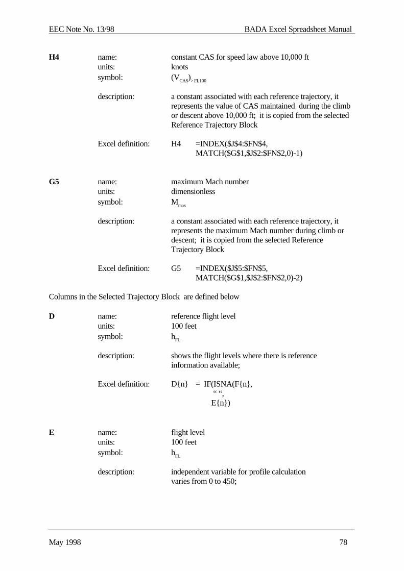
EEC Note No. 13/98 BADA Excel Spreadsheet Manual
May 1998 78
H4 name: constant CAS for speed law above 10,000 ftunits: knotssymbol: (VCAS)> FL100
description: a constant associated with each reference trajectory, itrepresents the value of CAS maintained during the climbor descent above 10,000 ft; it is copied from the selectedReference Trajectory Block
Excel definition: H4 =INDEX($J$4:$FN$4,MATCH($G$1,$J$2:$FN$2,0)-1)
G5 name: maximum Mach numberunits: dimensionlesssymbol: Mmax
description: a constant associated with each reference trajectory, itrepresents the maximum Mach number during climb ordescent; it is copied from the selected ReferenceTrajectory Block
Excel definition: G5 =INDEX($J$5:$FN$5,MATCH($G$1,$J$2:$FN$2,0)-2)
Columns in the Selected Trajectory Block are defined below
D name: reference flight levelunits: 100 feetsymbol: hFL
description: shows the flight levels where there is referenceinformation available;
Excel definition: D{n} = IF(ISNA(F{n}, “ “, E{n})
E name: flight levelunits: 100 feetsymbol: hFL
description: independent variable for profile calculationvaries from 0 to 450;
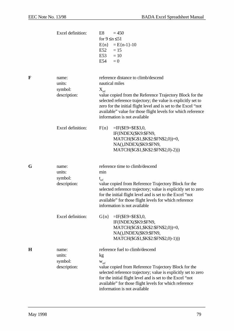
EEC Note No. 13/98 BADA Excel Spreadsheet Manual
May 1998 79
Excel definition: E8 = 450for 9 ≤n ≤51E{n} = E{n-1}-10E52 = 15E53 = 10E54 = 0
F name: reference distance to climb/descendunits: nautical milessymbol: Xref
description: value copied from the Reference Trajectory Block for theselected reference trajectory; the value is explicitly set tozero for the initial flight level and is set to the Excel “notavailable” value for those flight levels for which referenceinformation is not available
Excel definition: F{n} =IF($E9=$E$3,0,IF(INDEX($K9:$FN9,MATCH($G$1,$K$2:$FN$2,0))=0,NA(),INDEX($K9:$FN9,MATCH($G$1,$K$2:$FN$2,0)-2)))
G name: reference time to climb/descendunits: minsymbol: terf
description: value copied from Reference Trajectory Block for theselected reference trajectory; value is explicitly set to zerofor the initial flight level and is set to the Excel “notavailable” for those flight levels for which referenceinformation is not available
Excel definition: G{n} =IF($E9=$E$3,0,IF(INDEX($K9:$FN9,MATCH($G$1,$K$2:$FN$2,0))=0,NA(),INDEX($K9:$FN9,MATCH($G$1,$K$2:$FN$2,0)-1)))
H name: reference fuel to climb/descendunits: kgsymbol: wref
description: value copied from Reference Trajectory Block for theselected reference trajectory; value is explicitly set to zerofor the initial flight level and is set to the Excel “notavailable” for those flight levels for which referenceinformation is not available
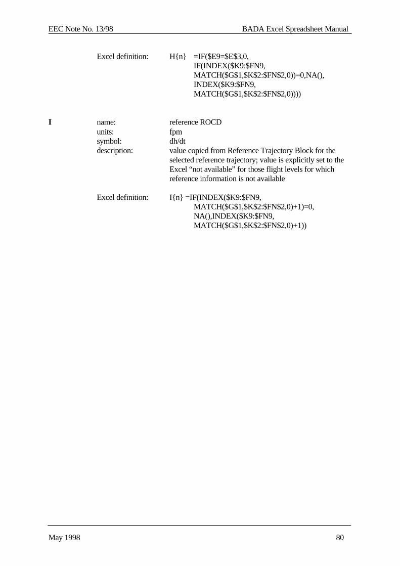
EEC Note No. 13/98 BADA Excel Spreadsheet Manual
May 1998 80
Excel definition: H{n} =IF($E9=$E$3,0,IF(INDEX($K9:$FN9,MATCH($G$1,$K$2:$FN$2,0))=0,NA(),INDEX($K9:$FN9,MATCH($G$1,$K$2:$FN$2,0))))
I name: reference ROCDunits: fpmsymbol: dh/dtdescription: value copied from Reference Trajectory Block for the
selected reference trajectory; value is explicitly set to theExcel “not available” for those flight levels for whichreference information is not available
Excel definition: I{n} =IF(INDEX($K9:$FN9,MATCH($G$1,$K$2:$FN$2,0)+1)=0,NA(),INDEX($K9:$FN9,MATCH($G$1,$K$2:$FN$2,0)+1))

EEC Note No. 13/98 BADA Excel Spreadsheet Manual
May 1998 81
3.2.3 Reference Trajectory Blocks for Climb and Descent Profiles
A Reference Trajectory Block holds the data corresponding to a reference climb ,cruise or descenttrajectory. There are several such blocks in each <A/C>.XLS spreadsheet corresponding toprofiles for different conditions of mass, speed and temperature. For the cruise data, only oneblock (the last one) is available. This profile has a different format and will be described inSection 3.2.4.
Each Reference Trajectory Block consists of four columns of the <A/C>.XLS spreadsheet. Anexample is shown in Figure 3.2.3-1 below. Rows 1 through 7 contain header information thatapplies globally to the profile. Rows 8 through 54 contain distance, time, fuel and ROCD data asa function of flight level.
All fields that require data entry by the user are shown in blue on the screen.
Figure 3.2.3-1: Reference Trajectory Block (Climb and Descent)
Individual cells in header of the Reference Trajectory Block are defined below. Note that theColumn letter is valid only for the example shown in Figure 3.2.3-1.
123456789
1011121314151617181920
J K L M N
trajectory: nom. spd/min mass/ISA B747
delta T 0 deg. C CL1
mass 190 tonnes climb
max CAS 310 310 knots
max Mach 0.820 minimum FL 15
LEVEL DIST TIME FUEL ROCD
[n. miles] [min] [kg] [fpm]
450
440 114.0 16.0 4500
430
420 97.0 13.0 4150
410
400 84.0 12.0 3850
390
380 75.0 11.0 3600
370
360 67.0 10.0 3400
350
340 61.0 9.0 3200
330
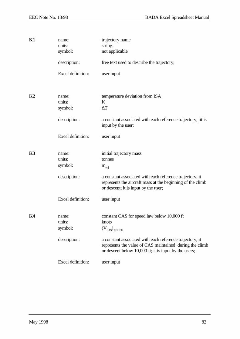
EEC Note No. 13/98 BADA Excel Spreadsheet Manual
May 1998 82
K1 name: trajectory nameunits: stringsymbol: not applicable
description: free text used to describe the trajectory;
Excel definition: user input
K2 name: temperature deviation from ISAunits: Ksymbol: ∆T
description: a constant associated with each reference trajectory; it isinput by the user;
Excel definition: user input
K3 name: initial trajectory massunits: tonnessymbol: mtraj
description: a constant associated with each reference trajectory, itrepresents the aircraft mass at the beginning of the climbor descent; it is input by the user;
Excel definition: user input
K4 name: constant CAS for speed law below 10,000 ftunits: knotssymbol: (VCAS)< FL100
description: a constant associated with each reference trajectory, itrepresents the value of CAS maintained during the climbor descent below 10,000 ft; it is input by the users;
Excel definition: user input
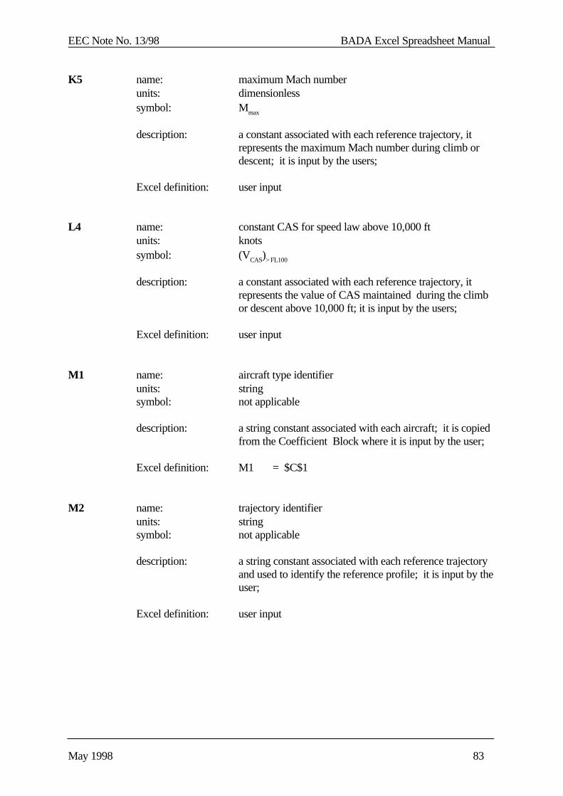
EEC Note No. 13/98 BADA Excel Spreadsheet Manual
May 1998 83
K5 name: maximum Mach numberunits: dimensionlesssymbol: Mmax
description: a constant associated with each reference trajectory, itrepresents the maximum Mach number during climb ordescent; it is input by the users;
Excel definition: user input
L4 name: constant CAS for speed law above 10,000 ftunits: knotssymbol: (VCAS)> FL100
description: a constant associated with each reference trajectory, itrepresents the value of CAS maintained during the climbor descent above 10,000 ft; it is input by the users;
Excel definition: user input
M1 name: aircraft type identifierunits: stringsymbol: not applicable
description: a string constant associated with each aircraft; it is copiedfrom the Coefficient Block where it is input by the user;
Excel definition: M1 = $C$1
M2 name: trajectory identifierunits: stringsymbol: not applicable
description: a string constant associated with each reference trajectoryand used to identify the reference profile; it is input by theuser;
Excel definition: user input
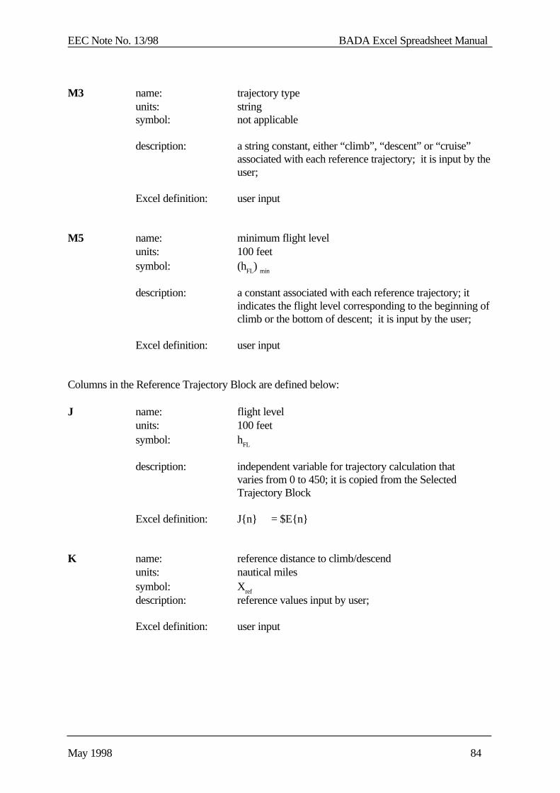
EEC Note No. 13/98 BADA Excel Spreadsheet Manual
May 1998 84
M3 name: trajectory typeunits: stringsymbol: not applicable
description: a string constant, either “climb”, “descent” or “cruise”associated with each reference trajectory; it is input by theuser;
Excel definition: user input
M5 name: minimum flight levelunits: 100 feetsymbol: (hFL) min
description: a constant associated with each reference trajectory; itindicates the flight level corresponding to the beginning ofclimb or the bottom of descent; it is input by the user;
Excel definition: user input
Columns in the Reference Trajectory Block are defined below:
J name: flight levelunits: 100 feetsymbol: hFL
description: independent variable for trajectory calculation thatvaries from 0 to 450; it is copied from the SelectedTrajectory Block
Excel definition: J{n} = $E{n}
K name: reference distance to climb/descendunits: nautical milessymbol: Xref
description: reference values input by user;
Excel definition: user input
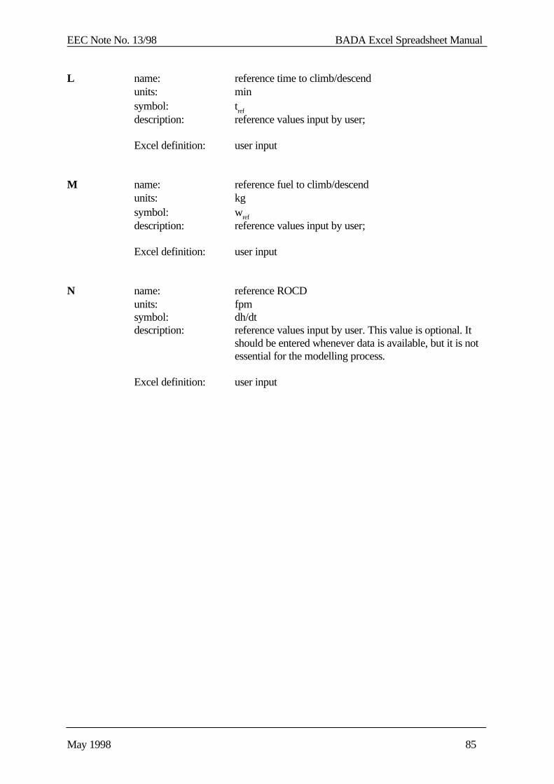
EEC Note No. 13/98 BADA Excel Spreadsheet Manual
May 1998 85
L name: reference time to climb/descendunits: minsymbol: tref
description: reference values input by user;
Excel definition: user input
M name: reference fuel to climb/descendunits: kgsymbol: wref
description: reference values input by user;
Excel definition: user input
N name: reference ROCDunits: fpmsymbol: dh/dtdescription: reference values input by user. This value is optional. It
should be entered whenever data is available, but it is notessential for the modelling process.
Excel definition: user input
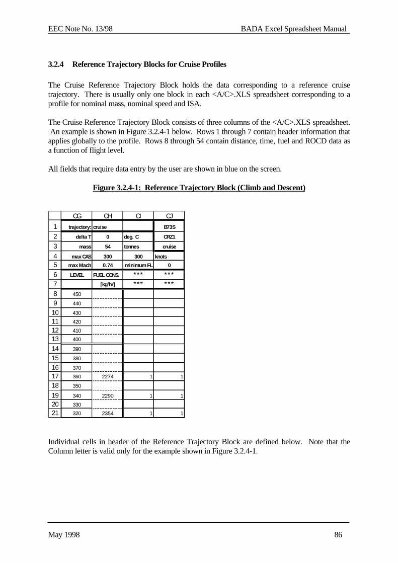
EEC Note No. 13/98 BADA Excel Spreadsheet Manual
May 1998 86
3.2.4 Reference Trajectory Blocks for Cruise Profiles
The Cruise Reference Trajectory Block holds the data corresponding to a reference cruisetrajectory. There is usually only one block in each <A/C>.XLS spreadsheet corresponding to aprofile for nominal mass, nominal speed and ISA.
The Cruise Reference Trajectory Block consists of three columns of the <A/C>.XLS spreadsheet. An example is shown in Figure 3.2.4-1 below. Rows 1 through 7 contain header information thatapplies globally to the profile. Rows 8 through 54 contain distance, time, fuel and ROCD data asa function of flight level.
All fields that require data entry by the user are shown in blue on the screen.
Figure 3.2.4-1: Reference Trajectory Block (Climb and Descent)
Individual cells in header of the Reference Trajectory Block are defined below. Note that theColumn letter is valid only for the example shown in Figure 3.2.4-1.
123456789
101112131415161718192021
CG CH CI CJ
trajectory: cruise B73S
delta T 0 deg. C CRZ1
mass 54 tonnes cruise
max CAS 300 300 knots
max Mach 0.74 minimum FL 0
LEVEL FUEL CONS. *** ***[kg/hr] *** ***
450
440
430
420
410
400
390
380
370
360 2274 1 1
350
340 2290 1 1
330
320 2354 1 1

EEC Note No. 13/98 BADA Excel Spreadsheet Manual
May 1998 87
CH1 name: trajectory nameunits: stringsymbol: not applicable
description: free text used to describe the trajectory;
Excel definition: user input
CH2 name: temperature deviation from ISAunits: Ksymbol: ∆T
description: a constant associated with each reference trajectory; it isinput by the user;
Excel definition: user input
CH3 name: trajectory massunits: tonnessymbol: mtraj
description: a constant associated with each reference trajectory
Excel definition: user input
CH4 name: constant CAS for speed law below 10,000 ftunits: knotssymbol: (VCAS)< FL100
description: a constant associated with each reference trajectory, itrepresents the value of CAS maintained below 10,000 ft; itis input by the users;
Excel definition: user input
CH5 name: maximum Mach numberunits: dimensionlesssymbol: Mmax
description: a constant associated with each reference trajectory, itrepresents the maximum Mach number; it is input by theusers;
Excel definition: user input
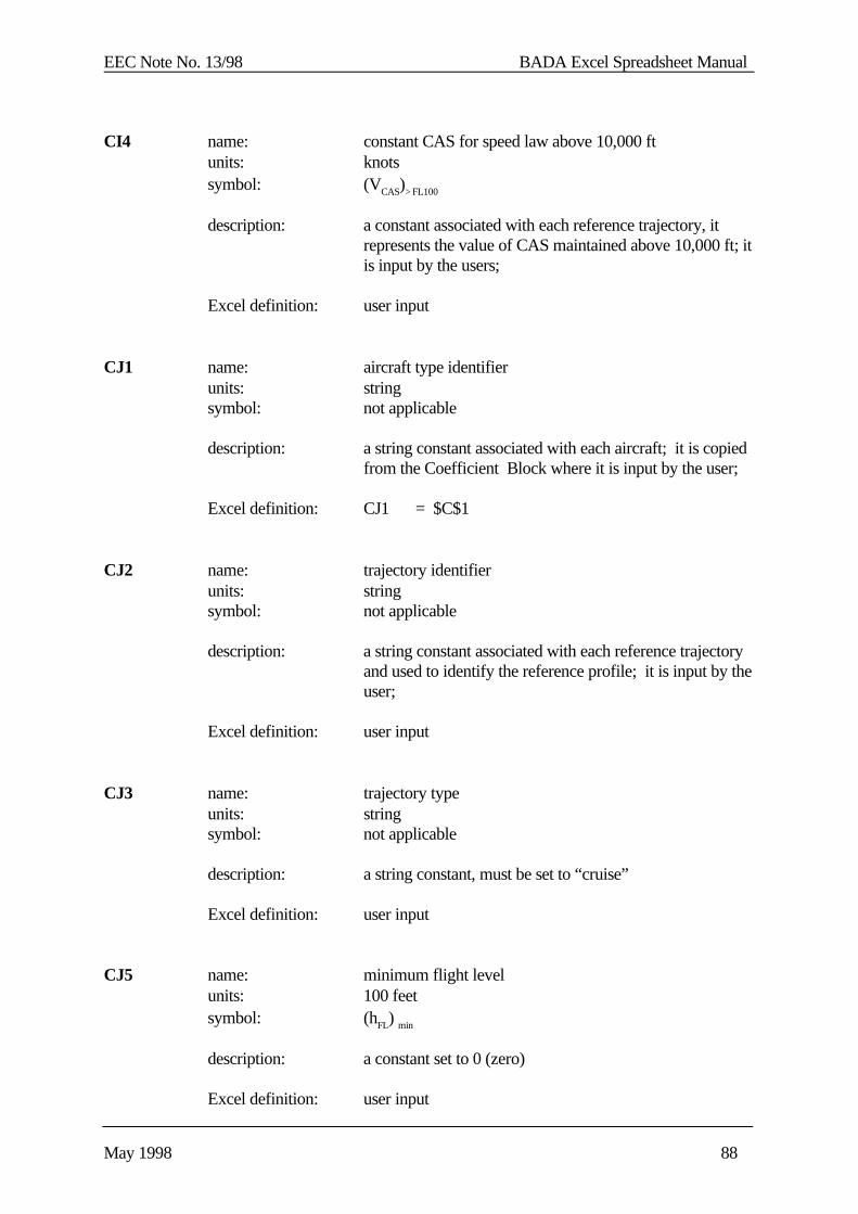
EEC Note No. 13/98 BADA Excel Spreadsheet Manual
May 1998 88
CI4 name: constant CAS for speed law above 10,000 ftunits: knotssymbol: (VCAS)> FL100
description: a constant associated with each reference trajectory, itrepresents the value of CAS maintained above 10,000 ft; itis input by the users;
Excel definition: user input
CJ1 name: aircraft type identifierunits: stringsymbol: not applicable
description: a string constant associated with each aircraft; it is copiedfrom the Coefficient Block where it is input by the user;
Excel definition: CJ1 = $C$1
CJ2 name: trajectory identifierunits: stringsymbol: not applicable
description: a string constant associated with each reference trajectoryand used to identify the reference profile; it is input by theuser;
Excel definition: user input
CJ3 name: trajectory typeunits: stringsymbol: not applicable
description: a string constant, must be set to “cruise”
Excel definition: user input
CJ5 name: minimum flight levelunits: 100 feetsymbol: (hFL) min
description: a constant set to 0 (zero)
Excel definition: user input
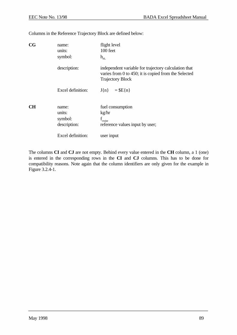
EEC Note No. 13/98 BADA Excel Spreadsheet Manual
May 1998 89
Columns in the Reference Trajectory Block are defined below:
CG name: flight levelunits: 100 feetsymbol: hFL
description: independent variable for trajectory calculation thatvaries from 0 to 450; it is copied from the SelectedTrajectory Block
Excel definition: J{n} = $E{n}
CH name: fuel consumptionunits: kg/hrsymbol: fcruise
description: reference values input by user;
Excel definition: user input
The columns CI and CJ are not empty. Behind every value entered in the CH column, a 1 (one)is entered in the corresponding rows in the CI and CJ columns. This has to be done forcompatibility reasons. Note again that the column identifiers are only given for the example inFigure 3.2.4-1.
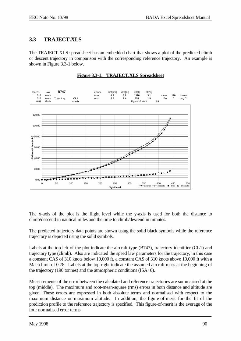
EEC Note No. 13/98 BADA Excel Spreadsheet Manual
May 1998 90
3.3 TRAJECT.XLS
The TRAJECT.XLS spreadsheet has an embedded chart that shows a plot of the predicted climbor descent trajectory in comparison with the corresponding reference trajectory. An example isshown in Figure 3.3-1 below.
Figure 3.3-1: TRAJECT.XLS Spreadsheet
The x-axis of the plot is the flight level while the y-axis is used for both the distance toclimb/descend in nautical miles and the time to climb/descend in minutes.
The predicted trajectory data points are shown using the solid black symbols while the referencetrajectory is depicted using the solid symbols.
Labels at the top left of the plot indicate the aircraft type (B747), trajectory identifier (CL1) andtrajectory type (climb). Also are indicated the speed law parameters for the trajectory, in this casea constant CAS of 310 knots below 10,000 ft, a constant CAS of 310 knots above 10,000 ft with aMach limit of 0.78. Labels at the top right indicate the assumed aircraft mass at the beginning ofthe trajectory (190 tonnes) and the atmospheric conditions (ISA+0).
Measurements of the error between the calculated and reference trajectories are summarised at thetop (middle). The maximum and root-mean-square (rms) errors in both distance and altitude aregiven. These errors are expressed in both absolute terms and normalised with respect to themaximum distance or maximum altitude. In addition, the figure-of-merit for the fit of theprediction profile to the reference trajectory is specified. This figure-of-merit is the average of thefour normalised error terms.
speeds law B747 errors dist[nm] dist[%] alt[ft] alt[%]310 knots max 4.3 3.8 1376 3.1 mass 190 tonnes310 knots Trajectory: CL1 rms 2.8 2.4 855 1.9 ISA 0 deg.C
0.82 Mach climb Figure of Merit: 2.8
0.00
20.00
40.00
60.00
80.00
100.00
120.00
0 50 100 150 200 250 300 350 400 450 500
flight level
dis
t (n
m)
/ tim
e (m
in)
distance dist.data time time.data
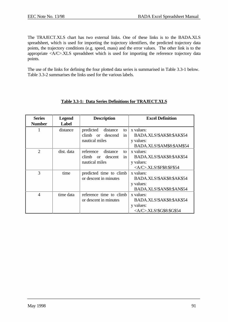
EEC Note No. 13/98 BADA Excel Spreadsheet Manual
May 1998 91
The TRAJECT.XLS chart has two external links. One of these links is to the BADA.XLSspreadsheet, which is used for importing the trajectory identifiers, the predicted trajectory datapoints, the trajectory conditions (e.g. speed, mass) and the error values. The other link is to theappropriate <A/C>.XLS spreadsheet which is used for importing the reference trajectory datapoints.
The use of the links for defining the four plotted data series is summarised in Table 3.3-1 below. Table 3.3-2 summarises the links used for the various labels.
Table 3.3-1: Data Series Definitions for TRAJECT.XLS
SeriesNumber
LegendLabel
Description Excel Definition
1 distance predicted distance toclimb or descend innautical miles
x values: BADA.XLS!$AK$8:$AK$54y values: BADA.XLS!$AM$8:$AM$54
2 dist. data reference distance toclimb or descent innautical miles
x values: BADA.XLS!$AK$8:$AK$54y values: <A/C>.XLS!$F$8:$F$54
3 time predicted time to climbor descent in minutes
x values: BADA.XLS!$AK$8:$AK$54y values: BADA.XLS!$AN$8:$AN$54
4 time data reference time to climbor descent in minutes
x values: BADA.XLS!$AK$8:$AK$54y values: <A/C>.XLS!$G$8:$G$54
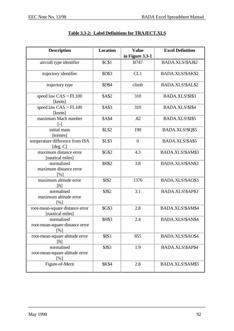
EEC Note No. 13/98 BADA Excel Spreadsheet Manual
May 1998 92
Table 3.3-2: Label Definitions for TRAJECT.XLS
Description Location Valuein Figure 3.3-1
Excel Definition
aircraft type identifier $C$1 B747 BADA.XLS!$AJ$2
trajectory identifier $D$3 CL1 BADA.XLS!$AK$2
trajectory type $D$4 climb BADA.XLS!$AL$2
speed law CAS < FL100[knots]
$A$2 310 BADA.XLS!$I$3
speed law CAS > FL100[knots]
$A$3 310 BADA.XLS!$I$4
maximum Mach number[-]
$A$4 .82 BADA.XLS!$I$5
initial mass[tonnes]
$L$2 190 BADA.XLS!$Q$5
temperature difference from ISA[deg. C]
$L$3 0 BADA.XLS!$A$5
maximum distance error[nautical miles]
$G$2 4.3 BADA.XLS!$AM$3
normalizedmaximum distance error
[%]
$H$2 3.8 BADA.XLS!$AN$3
maximum altitude error[ft]
$I$2 1376 BADA.XLS!$AO$3
normalisedmaximum altitude error
[%]
$J$2 3.1 BADA.XLS!$AP$3
root-mean-square distance error[nautical miles]
$G$3 2.8 BADA.XLS!$AM$4
normalised root-mean-square distance error
[%]
$H$3 2.4 BADA.XLS!$AN$4
root-mean-square altitude error[ft]
$I$3 855 BADA.XLS!$AO$4
normalisedroot-mean-square altitude error
[%]
$J$3 1.9 BADA.XLS!$AP$4
Figure-of-Merit $K$4 2.8 BADA.XLS!$AM$5

EEC Note No. 13/98 BADA Excel Spreadsheet Manual
May 1998 93
3.4 ROCD.XLS
The ROCD.XLS spreadsheet contains a chart that shows a plot of the predicted rate of climb ordescent and the reference rate of climb or descent if available. The reference rate of climb ordescent is an optional field in the trajectory block and usually only available when the referencedata comes from an aircraft performance program instead of a flight Manual. An example of anROCD.XLS spreadsheet is shown in Figure 3.4-1 below.
Figure 3.4-1: ROCD.XLS Chart
The x-axis of the plot is the flight level while the y-axis is used for the rate of climb or descent infeet per minute [fpm]. The predicted data points are shown using the solid black symbols. Thereference data points (if available) are shown in white
Labels at the top left of the plot indicate the aircraft type (B747), trajectory identifier (CL1) andtrajectory type (climb). Also indicated are the speed law parameters for the trajectory, in this casea constant CAS of 310 knots (both below and above 10,000 ft) with a Mach limit of 0.82. Labelsat the top right indicate the assumed aircraft mass at the beginning of the trajectory (190 tonnes)and the atmospheric conditions (ISA+0). The ROCD.XLs chart has two external links. One link isto the BADA.XLS spreadsheet, which is used for importing the trajectory identifiers, thepredicted rate of climb/descent data points, and the trajectory conditions (e.g. speed, mass). Theother link is to the <A/C>.XLS, which is used for importing the ROCD reference data.
speeds law B747310 knots310 knots Trajectory: CL1 mass 190 tonnes
0.82 Mach climb ROCD ISA 0 deg.C
0
1000
2000
3000
4000
5000
6000
7000
0 50 100 150 200 250 300 350 400 450 500
flight level
RO
CD
[ft
/min
]
ROCD ROCD data
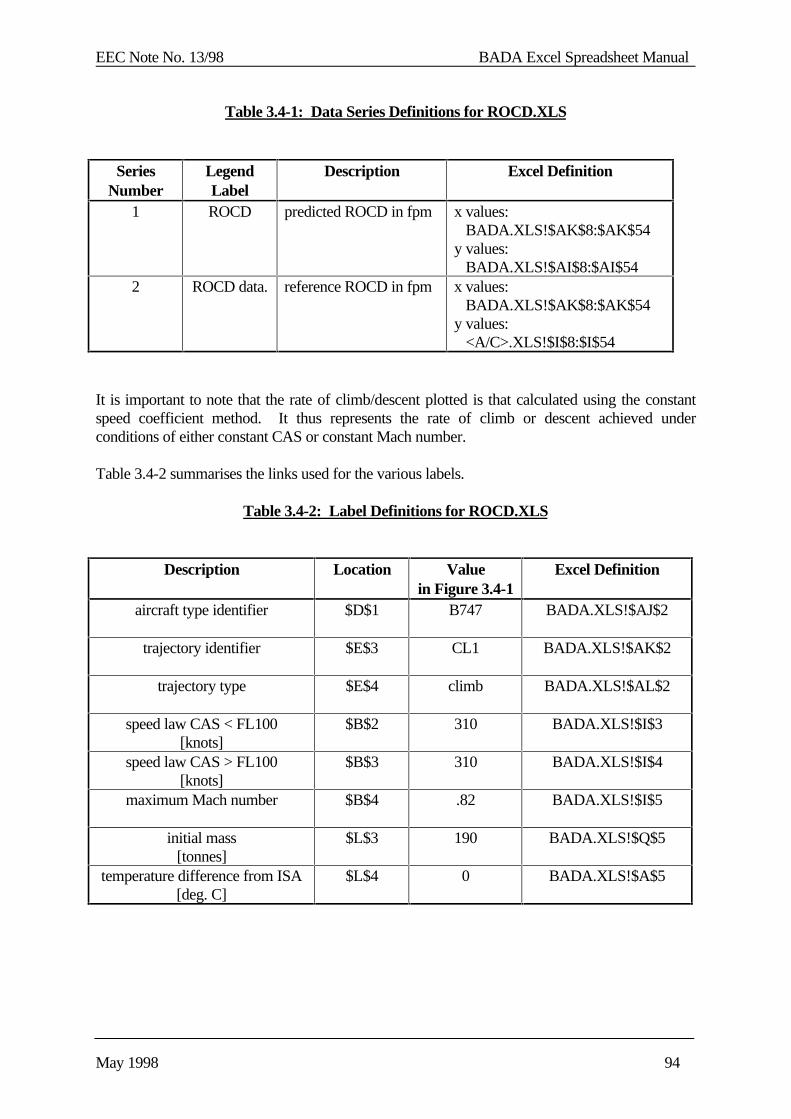
EEC Note No. 13/98 BADA Excel Spreadsheet Manual
May 1998 94
Table 3.4-1: Data Series Definitions for ROCD.XLS
SeriesNumber
LegendLabel
Description Excel Definition
1 ROCD predicted ROCD in fpm x values: BADA.XLS!$AK$8:$AK$54y values: BADA.XLS!$AI$8:$AI$54
2 ROCD data. reference ROCD in fpm x values: BADA.XLS!$AK$8:$AK$54y values: <A/C>.XLS!$I$8:$I$54
It is important to note that the rate of climb/descent plotted is that calculated using the constantspeed coefficient method. It thus represents the rate of climb or descent achieved underconditions of either constant CAS or constant Mach number.
Table 3.4-2 summarises the links used for the various labels.
Table 3.4-2: Label Definitions for ROCD.XLS
Description Location Valuein Figure 3.4-1
Excel Definition
aircraft type identifier $D$1 B747 BADA.XLS!$AJ$2
trajectory identifier $E$3 CL1 BADA.XLS!$AK$2
trajectory type $E$4 climb BADA.XLS!$AL$2
speed law CAS < FL100[knots]
$B$2 310 BADA.XLS!$I$3
speed law CAS > FL100[knots]
$B$3 310 BADA.XLS!$I$4
maximum Mach number $B$4 .82 BADA.XLS!$I$5
initial mass[tonnes]
$L$3 190 BADA.XLS!$Q$5
temperature difference from ISA[deg. C]
$L$4 0 BADA.XLS!$A$5
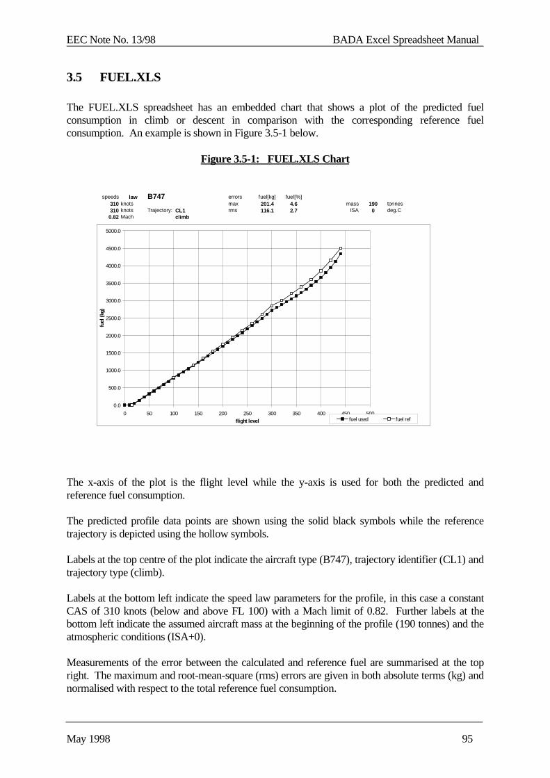
EEC Note No. 13/98 BADA Excel Spreadsheet Manual
May 1998 95
3.5 FUEL.XLS
The FUEL.XLS spreadsheet has an embedded chart that shows a plot of the predicted fuelconsumption in climb or descent in comparison with the corresponding reference fuelconsumption. An example is shown in Figure 3.5-1 below.
Figure 3.5-1: FUEL.XLS Chart
The x-axis of the plot is the flight level while the y-axis is used for both the predicted andreference fuel consumption.
The predicted profile data points are shown using the solid black symbols while the referencetrajectory is depicted using the hollow symbols.
Labels at the top centre of the plot indicate the aircraft type (B747), trajectory identifier (CL1) andtrajectory type (climb).
Labels at the bottom left indicate the speed law parameters for the profile, in this case a constantCAS of 310 knots (below and above FL 100) with a Mach limit of 0.82. Further labels at thebottom left indicate the assumed aircraft mass at the beginning of the profile (190 tonnes) and theatmospheric conditions (ISA+0).
Measurements of the error between the calculated and reference fuel are summarised at the topright. The maximum and root-mean-square (rms) errors are given in both absolute terms (kg) andnormalised with respect to the total reference fuel consumption.
speeds law B747 errors fuel[kg] fuel[%]310 knots max 201.4 4.6 mass 190 tonnes310 knots Trajectory: CL1 rms 116.1 2.7 ISA 0 deg.C
0.82 Mach climb
0.0
500.0
1000.0
1500.0
2000.0
2500.0
3000.0
3500.0
4000.0
4500.0
5000.0
0 50 100 150 200 250 300 350 400 450 500flight level
fuel
(kg)
fuel used fuel ref
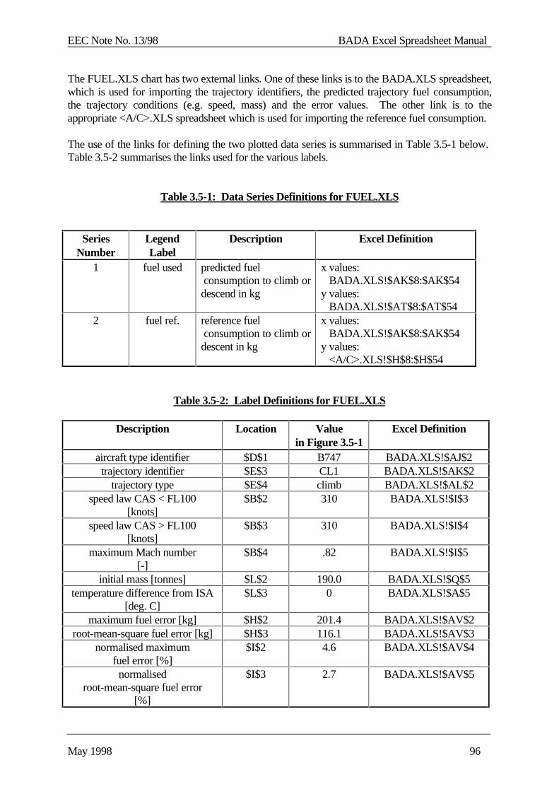
EEC Note No. 13/98 BADA Excel Spreadsheet Manual
May 1998 96
The FUEL.XLS chart has two external links. One of these links is to the BADA.XLS spreadsheet,which is used for importing the trajectory identifiers, the predicted trajectory fuel consumption,the trajectory conditions (e.g. speed, mass) and the error values. The other link is to theappropriate <A/C>.XLS spreadsheet which is used for importing the reference fuel consumption.
The use of the links for defining the two plotted data series is summarised in Table 3.5-1 below. Table 3.5-2 summarises the links used for the various labels.
Table 3.5-1: Data Series Definitions for FUEL.XLS
SeriesNumber
LegendLabel
Description Excel Definition
1 fuel used predicted fuel consumption to climb ordescend in kg
x values: BADA.XLS!$AK$8:$AK$54y values: BADA.XLS!$AT$8:$AT$54
2 fuel ref. reference fuel consumption to climb ordescent in kg
x values: BADA.XLS!$AK$8:$AK$54y values: <A/C>.XLS!$H$8:$H$54
Table 3.5-2: Label Definitions for FUEL.XLS
Description Location Valuein Figure 3.5-1
Excel Definition
aircraft type identifier $D$1 B747 BADA.XLS!$AJ$2trajectory identifier $E$3 CL1 BADA.XLS!$AK$2
trajectory type $E$4 climb BADA.XLS!$AL$2speed law CAS < FL100
[knots]$B$2 310 BADA.XLS!$I$3
speed law CAS > FL100[knots]
$B$3 310 BADA.XLS!$I$4
maximum Mach number[-]
$B$4 .82 BADA.XLS!$I$5
initial mass [tonnes] $L$2 190.0 BADA.XLS!$Q$5temperature difference from ISA
[deg. C]$L$3 0 BADA.XLS!$A$5
maximum fuel error [kg] $H$2 201.4 BADA.XLS!$AV$2root-mean-square fuel error [kg] $H$3 116.1 BADA.XLS!$AV$3
normalised maximumfuel error [%]
$I$2 4.6 BADA.XLS!$AV$4
normalisedroot-mean-square fuel error
[%]
$I$3 2.7 BADA.XLS!$AV$5
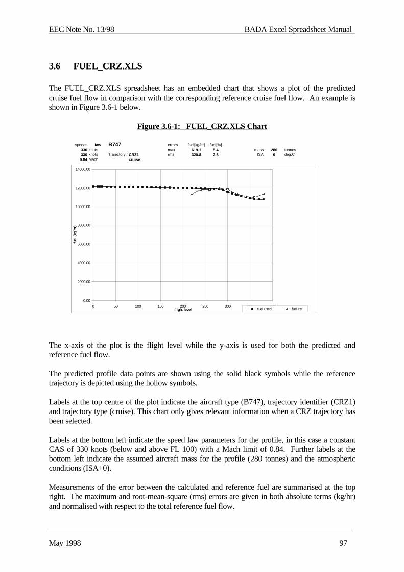
EEC Note No. 13/98 BADA Excel Spreadsheet Manual
May 1998 97
3.6 FUEL_CRZ.XLS
The FUEL_CRZ.XLS spreadsheet has an embedded chart that shows a plot of the predictedcruise fuel flow in comparison with the corresponding reference cruise fuel flow. An example isshown in Figure 3.6-1 below.
Figure 3.6-1: FUEL_CRZ.XLS Chart
The x-axis of the plot is the flight level while the y-axis is used for both the predicted andreference fuel flow.
The predicted profile data points are shown using the solid black symbols while the referencetrajectory is depicted using the hollow symbols.
Labels at the top centre of the plot indicate the aircraft type (B747), trajectory identifier (CRZ1)and trajectory type (cruise). This chart only gives relevant information when a CRZ trajectory hasbeen selected.
Labels at the bottom left indicate the speed law parameters for the profile, in this case a constantCAS of 330 knots (below and above FL 100) with a Mach limit of 0.84. Further labels at thebottom left indicate the assumed aircraft mass for the profile (280 tonnes) and the atmosphericconditions (ISA+0).
Measurements of the error between the calculated and reference fuel are summarised at the topright. The maximum and root-mean-square (rms) errors are given in both absolute terms (kg/hr)and normalised with respect to the total reference fuel flow.
speeds law B747 errors fuel[kg/hr] fuel[%]330 knots max 619.1 5.4 mass 280 tonnes330 knots Trajectory: CRZ1 rms 320.8 2.8 ISA 0 deg.C
0.84 Mach cruise
0.00
2000.00
4000.00
6000.00
8000.00
10000.00
12000.00
14000.00
0 50 100 150 200 250 300 350 400flight level
fuel
(kg/
hr)
fuel used fuel ref

EEC Note No. 13/98 BADA Excel Spreadsheet Manual
May 1998 98
The FUEL_CRZ.XLS chart has two external links. One of these links is to the BADA.XLSspreadsheet, which is used for importing the trajectory identifiers, the predicted trajectory fuelconsumption, the trajectory conditions (e.g. speed, mass) and the error values. The other link is tothe appropriate <A/C>.XLS spreadsheet which is used for importing the reference fuel flow.
The use of the links for defining the two plotted data series is summarised in Table 3.6-1 below. Table 3.6-2 summarises the links used for the various labels.
Table 3.6-1: Data Series Definitions for FUEL_CRZ.XLS
SeriesNumber
LegendLabel
Description Excel Definition
1 fuel used predicted cruise fuelflow in kg/hr
x values: BADA.XLS!$AK$8:$AK$54y values: BADA.XLS!$AX$8:$AX$54
2 fuel ref. reference cruise fuelflow in kg/hr
x values: BADA.XLS!$AK$8:$AK$54y values: <A/C>.XLS!$F$8:$F$54
Table 3.6-2: Label Definitions for FUEL_CRZ.XLS
Description Location Valuein Figure 3.6-1
Excel Definition
aircraft type identifier $D$1 B747 BADA.XLS!$AJ$2trajectory identifier $E$3 CRZ1 BADA.XLS!$AK$2
trajectory type $E$4 cruise BADA.XLS!$AL$2speed law CAS < FL100
[knots]$B$2 330 BADA.XLS!$I$3
speed law CAS > FL100[knots]
$B$3 330 BADA.XLS!$I$4
maximum Mach number $B$4 .84 BADA.XLS!$I$5mass [tonnes] $L$2 280.0 BADA.XLS!$Q$5
temperature difference from ISA[deg. C]
$L$3 0 BADA.XLS!$A$5
maximum fuel error [kg/hr] $H$2 201.4 BADA.XLS!$BA$2root-mean-square fuel error
[kg/hr]$H$3 116.1 BADA.XLS!$BA$3
normalised maximumfuel error [%]
$I$2 4.6 BADA.XLS!$BA$4
normalised root-mean-squarefuel error [%]
$I$3 2.7 BADA.XLS!$BA$5
EEC Note No. 13/98 BADA Excel Spreadsheet Manual
May 1998 99
4. PROCEDURES FOR USE
This section describes how the BADA Excel spreadsheets are used for the preparation of a BADAaircraft model. This preparation process consists of the following eight stages, each of which isseparately described by a subsection below.
(i) Acquisition of Reference Information
(ii) Initialisation of Aircraft Modelling Report
(iii) Initialisation of a <A/C>.XLS Spreadsheet
(iv) Determination of Thrust and Drag Coefficients
(v) Determination of Thrust Temperature Coefficients
(vi) Determination of Fuel Flow Coefficients
(vii) Dynamic Maximum Altitude parameters
(viii) Buffeting Parameters
(ix) Update of APF and OPF Files
(x) Create PTF file
(xi) Completion of Aircraft Modelling Report
(xii) Use of SOLV.XLS spreadsheet
4.1 Acquisition of Reference Information
The first step in the preparation of a BADA aircraft model is the acquisition of referenceinformation. The main source of information is A/C Operation Manuals as published by themanufacturer or by operating airlines. In particular, the A/C Operation Manuals contain a numberof reference climb and descent profiles which specify, in either tabular or graphical form, theclimb and descent performance of the aircraft at various mass, speed and temperature conditions. It is primarily these reference profiles which are used for the generation of the BADA thrust, dragand fuel coefficients. Other sources of information are the aircraft performance programs that areavailable to APO. Currently these progrmas are available for the Airbus family (PEP program)and ATR family (FOS program). These programs offer the user a level of flexibility and accuracythat cannot be matched by the Flight Manual. They also provide the user with a number ofparameters that are normally not available (drag coefficients, thrust level, angle of attack etc.)Reference data from these programs should be used whenever available. User Manuals for bothprograms are available from the APO library.
EEC Note No. 13/98 BADA Excel Spreadsheet Manual
May 1998 100
It is possible to generate BADA coefficients using only one reference climb and one referencedescent profile. However, in order to have coefficients that can robustly represent the aircraftbehaviour over a variety of conditions the following number of profiles is recommended:
(a) one descent profile at ISA conditions for a nominal mass and speed;
(b) three climb profiles at ISA conditions for the nominal speed and representingminimum, nominal and maximum mass conditions;
(c) three climb profiles at ISA conditions for an alternative speed and representingminimum, nominal and maximum mass conditions;
(d) three climb profiles at ISA+10 conditions for the nominal speed and representingminimum, nominal and maximum mass conditions; and,
(e) one climb profile at ISA+20 conditions for the nominal speed and mass.
(f) one cruise profile for the nominal speed, nominal weight and ISA conditions.
Currently, the reference information is obtained by members of RTO and APO CoE throughadhoc contacts with airlines and national certification agencies. All reference manuals that areobtained, are maintained by APO within an A/C Performance Library.
A secondary source of information is Jane’s All the World’s Aircraft which is published annually.Jane’s is suitable for providing information such as maximum weights, dimensions, and maximumoperating speeds but it does not provide reference climb or descent profiles. Copies of Jane’s Allthe World’s Aircraft for each year are also maintained by APO within an A/C PerformanceLibrary.
It is important to note that BADA provides just one aircraft model for each aircraft type asdistinguished by an ICAO Aircraft Type Designator [RD3]. Each ICAO designator may be usedfor several series of aircraft. As an example, the H25B designator represents the following seriesof the Hawker Siddely 125 aircraft:
Series 1/1A/1BSeries 2Series 3/3A/3BSeries 400A/BSeries 600A/BSeries 700A/BSeries 800A/B
Each of the different series will have different performance due to changes in the airframe (e.g.extended fuselage) or engines.
The first decision for the modelling process is thus to decide which aircraft series to base theBADA model upon. If possible, the selected series should be that which is most commonly usedin the European airspace. Both Jane's and Flight International provide statistics on the number ofdifferent series of each aircraft that has been sold or continue to be operated. This informationcan be used when making a decision.
EEC Note No. 13/98 BADA Excel Spreadsheet Manual
May 1998 101
Unfortunately, most often the decision is limited by the availability of reference information. Inthis case, the choice which series to use as a basis is set to that series for which referenceinformation has been obtained.
Regardless of why a particular model is chosen, it is important to note that all further decisions onBADA coefficients must be consistent with the chosen series.
It should also be noted that while it may be acceptable to produce a model based on whateverreference information is available, the model should be regenerated if more suitable referenceinformation becomes available. As an example, the version of the H25B model for BADARevision 3.0 is based on the HS-125/3B aircraft. This is an older version, which accounts forapproximately 5% of the HS-125 aircraft in operation. When available, a revised model shouldbe generated that is based on a series 700 or 800 aircraft which accounts for a much largerproportion of the HS-125 aircraft operating today.
4.2 Initialisation of Aircraft Modelling Report
The preparation of each BADA aircraft model is documented by a BADA Modelling Report. Thepurpose of this report is to record the source of all reference information used for the generationof the model and to record the decisions made during the modelling process.
All BADA Modelling Reports follow a standard format. Examples of this format can be found inthe reports for the Boeing 737-500 or the Dornier 328 aircraft [RD5 and RD6]. Followingstandard Eurocontrol practice, the BADA Modelling Reports are written using Microsoft Word. Some earlier reports have been written using WordPerfect.
For a new aircraft model, the BADA Modelling Report is initialised as a copy of a report foranother aircraft. For example, the report for the Fokker 70 aircraft was initialised as a copy of thereport for the previously modelled Fokker 100. Once an initial copy of the report is made, anumber of edits are done to change the report title, page headers, page footers and introductorysections as appropriate for the aircraft under consideration. Following this, summary tables ofaircraft parameters and reference profiles are updated in Section 2 of the report.
An example of a Parameter Summary Table for the Dornier 328 is shown below as Table 4.2-1. This table would be Table 2-1 in the modelling report. Note that the references in this table referto references of the A/C Modelling Report and not to references in this document. The ParameterSummary Table contains a list of parameters that must be extracted from the referenceinformation for each aircraft to be modelled. For every parameter a reference including pagenumber must be given. This ensures that all values can be traced back to the original source.
Some points to remember when extracting these parameters are given below.
(a) The BADA reference mass is typically chosen to be 70% of the way between theminimum (operational empty mass) and the maximum (maximum take-off) mass whilecorresponding to a mass value for which reference climb and descent profiles areavailable. This is thus typically a multiple of 1000 or 500 kg.
(b) The service ceiling should be specified while allowing for 300 fpm climb.
(c) Stall speeds refer to the minimum stall speed in a configuration and not the 1-g stall speed.

EEC Note No. 13/98 BADA Excel Spreadsheet Manual
May 1998 102
(d) The BADA reference descent speed must correspond to the speed for which the referencedescent profile is available. This is typically but not necessarily the same as the nominaldescent speed.
(e) The maximum altitude at MTOW and ISA can be the same as the (absolute) maximumaltitude. This is normally the case for smaller aircraft. For the larger jet aircraft howeverthere is usually a distinct difference between the two.
(f) The temperature and weight gradients can usually be found by examining the flight
envelope given in the manuals. If Gw can not be determined using Flight Manual
information than the following approximation may be used: Gw= 23500 / MTOW. Gt cannot be approximated which means that it will be set to 0 (zero) if no temperatureinformation is available. Note that the temperature and weight gradients are not usedduring the spreadsheet calculation and that they maybe entered at the end of the process.
Table 4.2-1: D328 Parameter Summary
Parameter Value Source Reference
manufacturer series Series 100 [RD3] pg 01
number of engines andengine type
two 1380 kW turbopropsPratt & Whitney Canada PW119B
[RD2] pg 98
ICAO wake category M (medium) [RD1] pg 2-4
mass (kg) maximum: 13640 (maximum take-off)minimum: 8810 (operating weight empty)maximum payload: 3450reference: 12000
[RD3] pg 03-03
[RD3] pg 08-03
[RD3] pg 08-03
maximum operatingspeed
CAS (knots): 270Mach: 0.59
[RD3] pg A1-01-02[RD3] pg A1-01-02
maximum altitude(ft above sea level)
32800service ceiling with 300 fpm climb
[RD3] pg A1-02-01
reference aerodynamicsurface area ( m2 )
40.0 [RD3] pg 06-01
stall speed(knots, CAS)
cruise: 109climb: 109take-off: 109 approach: 109landing: 90
[RD3] pg A1-01-02
nominal climb speed 180 kts / 0.59 M [RD3] pg A1-30-06
nominal cruise speed 270 kts / 0.59 M [RD3] pg 03-05
nominal descent speed 250 kts /270 kts / 0.59 M [RD3] pg A1-50-03
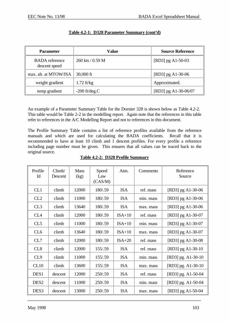
EEC Note No. 13/98 BADA Excel Spreadsheet Manual
May 1998 103
Table 4.2-1: D328 Parameter Summary (cont’d)
Parameter Value Source Reference
BADA referencedescent speed
260 kts / 0.59 M [RD3] pg A1-50-03
max. alt. at MTOW/ISA 30,000 ft [RD3] pg A1-30-06
weight gradient 1.72 ft/kg Approximated.
temp gradient -200 ft/deg.C [RD3] pg A1-30-06/07
An example of a Parameter Summary Table for the Dornier 328 is shown below as Table 4.2-2. This table would be Table 2-2 in the modelling report. Again note that the references in this tablerefer to references in the A/C Modelling Report and not to references in this document.
The Profile Summary Table contains a list of reference profiles available from the referencemanuals and which are used for calculating the BADA coefficients. Recall that it isrecommended to have at least 10 climb and 1 descent profiles. For every profile a referenceincluding page number must be given. This ensures that all values can be traced back to theoriginal source.
Table 4.2-2: D328 Profile Summary
Profile Id
Climb/Descent
Mass(kg)
SpeedLaw
(CAS/M)
Atm. Comments ReferenceSource
CL1 climb 12000 180/.59 ISA ref. mass [RD3] pg A1-30-06
CL2 climb 11000 180/.59 ISA min. mass [RD3] pg A1-30-06
CL3 climb 13640 180/.59 ISA max. mass [RD3] pg A1-30-06
CL4 climb 12000 180/.59 ISA+10 ref. mass [RD3] pg A1-30-07
CL5 climb 11000 180/.59 ISA+10 min. mass [RD3] pg A1-30-07
CL6 climb 13640 180/.59 ISA+10 max. mass [RD3] pg A1-30-07
CL7 climb 12000 180/.59 ISA+20 ref. mass [RD3] pg A1-30-08
CL8 climb 12000 155/.59 ISA ref. mass [RD3] pg A1-30-10
CL9 climb 11000 155/.59 ISA min. mass [RD3] pg. A1-30-10
CL10 climb 13600 155/.59 ISA max. mass [RD3] pg. A1-30-10
DES1 descent 12000 250/.59 ISA ref. mass [RD3] pg. A1-50-04
DES2 descent 11000 250/.59 ISA min. mass [RD3] pg. A1-50-04
DES3 descent 13000 250/.59 ISA max. mass [RD3] pg A1-50-04
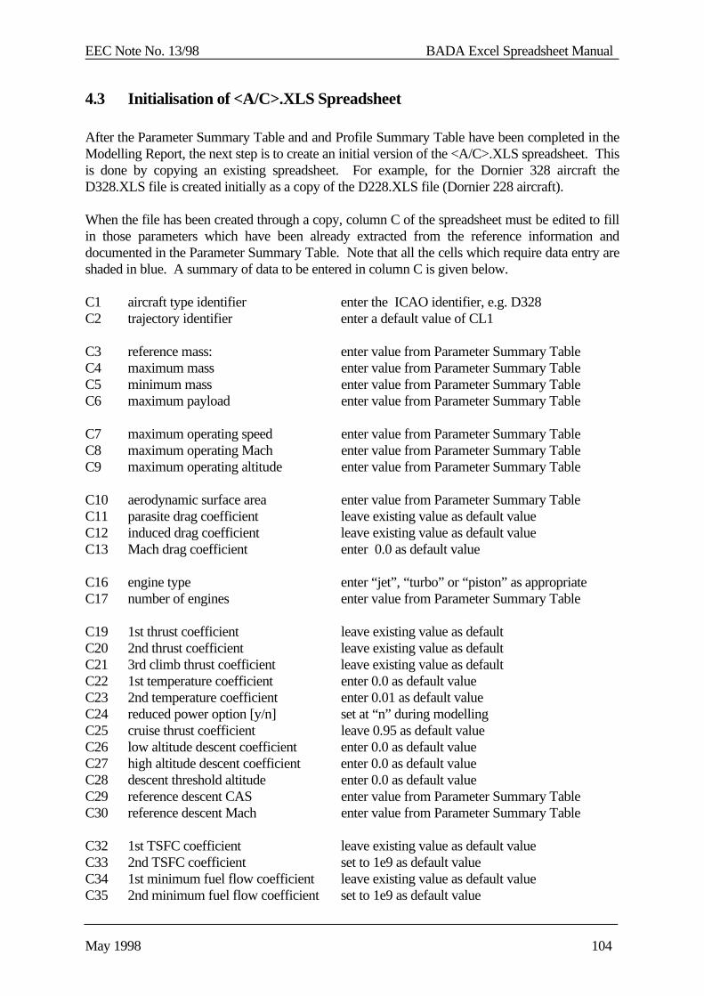
EEC Note No. 13/98 BADA Excel Spreadsheet Manual
May 1998 104
4.3 Initialisation of <A/C>.XLS Spreadsheet
After the Parameter Summary Table and and Profile Summary Table have been completed in theModelling Report, the next step is to create an initial version of the <A/C>.XLS spreadsheet. Thisis done by copying an existing spreadsheet. For example, for the Dornier 328 aircraft theD328.XLS file is created initially as a copy of the D228.XLS file (Dornier 228 aircraft).
When the file has been created through a copy, column C of the spreadsheet must be edited to fillin those parameters which have been already extracted from the reference information anddocumented in the Parameter Summary Table. Note that all the cells which require data entry areshaded in blue. A summary of data to be entered in column C is given below.
C1 aircraft type identifier enter the ICAO identifier, e.g. D328C2 trajectory identifier enter a default value of CL1
C3 reference mass: enter value from Parameter Summary TableC4 maximum mass enter value from Parameter Summary TableC5 minimum mass enter value from Parameter Summary TableC6 maximum payload enter value from Parameter Summary Table
C7 maximum operating speed enter value from Parameter Summary TableC8 maximum operating Mach enter value from Parameter Summary TableC9 maximum operating altitude enter value from Parameter Summary Table
C10 aerodynamic surface area enter value from Parameter Summary TableC11 parasite drag coefficient leave existing value as default valueC12 induced drag coefficient leave existing value as default valueC13 Mach drag coefficient enter 0.0 as default value
C16 engine type enter “jet”, “turbo” or “piston” as appropriateC17 number of engines enter value from Parameter Summary Table
C19 1st thrust coefficient leave existing value as defaultC20 2nd thrust coefficient leave existing value as defaultC21 3rd climb thrust coefficient leave existing value as defaultC22 1st temperature coefficient enter 0.0 as default valueC23 2nd temperature coefficient enter 0.01 as default valueC24 reduced power option [y/n] set at “n” during modellingC25 cruise thrust coefficient leave 0.95 as default valueC26 low altitude descent coefficient enter 0.0 as default valueC27 high altitude descent coefficient enter 0.0 as default valueC28 descent threshold altitude enter 0.0 as default valueC29 reference descent CAS enter value from Parameter Summary TableC30 reference descent Mach enter value from Parameter Summary Table
C32 1st TSFC coefficient leave existing value as default valueC33 2nd TSFC coefficient set to 1e9 as default valueC34 1st minimum fuel flow coefficient leave existing value as default valueC35 2nd minimum fuel flow coefficient set to 1e9 as default value
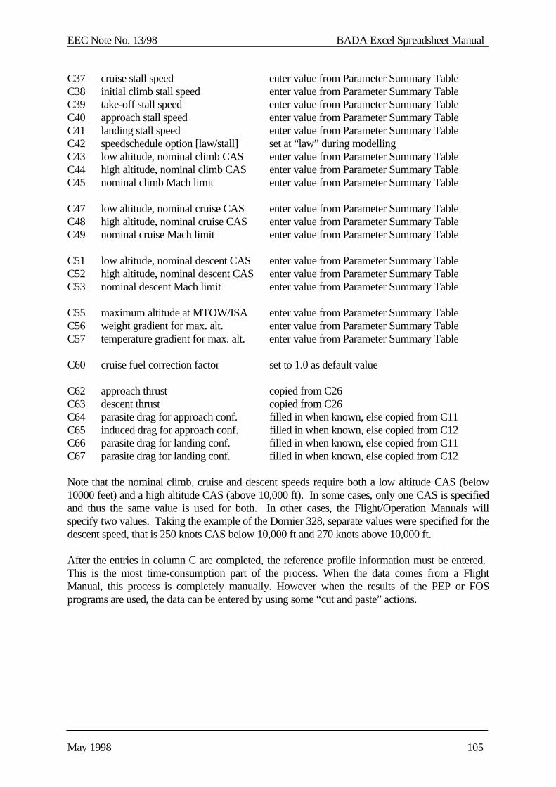
EEC Note No. 13/98 BADA Excel Spreadsheet Manual
May 1998 105
C37 cruise stall speed enter value from Parameter Summary TableC38 initial climb stall speed enter value from Parameter Summary TableC39 take-off stall speed enter value from Parameter Summary TableC40 approach stall speed enter value from Parameter Summary TableC41 landing stall speed enter value from Parameter Summary TableC42 speedschedule option [law/stall] set at “law” during modellingC43 low altitude, nominal climb CAS enter value from Parameter Summary TableC44 high altitude, nominal climb CAS enter value from Parameter Summary TableC45 nominal climb Mach limit enter value from Parameter Summary Table
C47 low altitude, nominal cruise CAS enter value from Parameter Summary TableC48 high altitude, nominal cruise CAS enter value from Parameter Summary TableC49 nominal cruise Mach limit enter value from Parameter Summary Table
C51 low altitude, nominal descent CAS enter value from Parameter Summary TableC52 high altitude, nominal descent CAS enter value from Parameter Summary TableC53 nominal descent Mach limit enter value from Parameter Summary Table
C55 maximum altitude at MTOW/ISA enter value from Parameter Summary TableC56 weight gradient for max. alt. enter value from Parameter Summary TableC57 temperature gradient for max. alt. enter value from Parameter Summary Table
C60 cruise fuel correction factor set to 1.0 as default value
C62 approach thrust copied from C26C63 descent thrust copied from C26C64 parasite drag for approach conf. filled in when known, else copied from C11C65 induced drag for approach conf. filled in when known, else copied from C12C66 parasite drag for landing conf. filled in when known, else copied from C11C67 parasite drag for landing conf. filled in when known, else copied from C12
Note that the nominal climb, cruise and descent speeds require both a low altitude CAS (below10000 feet) and a high altitude CAS (above 10,000 ft). In some cases, only one CAS is specifiedand thus the same value is used for both. In other cases, the Flight/Operation Manuals willspecify two values. Taking the example of the Dornier 328, separate values were specified for thedescent speed, that is 250 knots CAS below 10,000 ft and 270 knots above 10,000 ft.
After the entries in column C are completed, the reference profile information must be entered. This is the most time-consumption part of the process. When the data comes from a FlightManual, this process is completely manually. However when the results of the PEP or FOSprograms are used, the data can be entered by using some “cut and paste” actions.
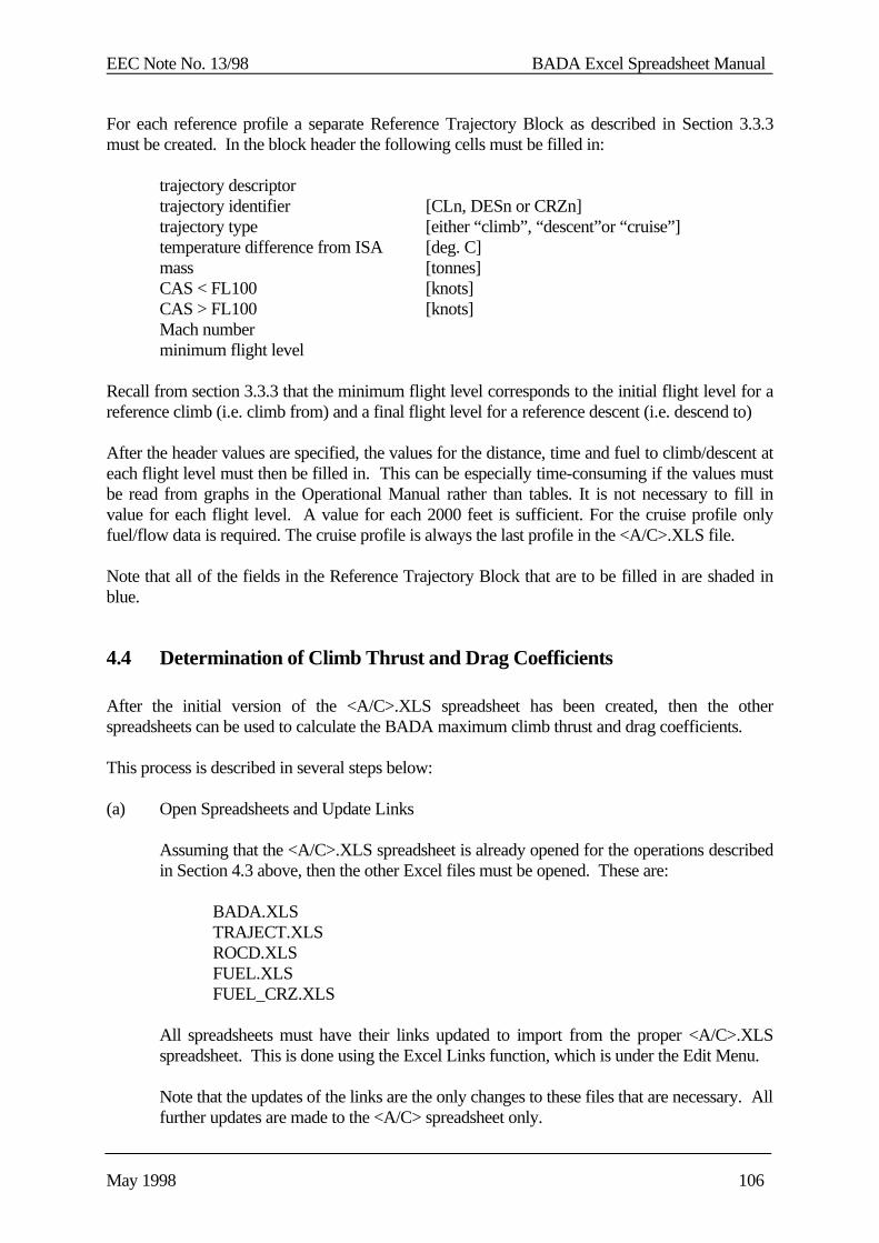
EEC Note No. 13/98 BADA Excel Spreadsheet Manual
May 1998 106
For each reference profile a separate Reference Trajectory Block as described in Section 3.3.3must be created. In the block header the following cells must be filled in:
trajectory descriptortrajectory identifier [CLn, DESn or CRZn]trajectory type [either “climb”, “descent”or “cruise”]temperature difference from ISA [deg. C]mass [tonnes]CAS < FL100 [knots]CAS > FL100 [knots]Mach numberminimum flight level
Recall from section 3.3.3 that the minimum flight level corresponds to the initial flight level for areference climb (i.e. climb from) and a final flight level for a reference descent (i.e. descend to)
After the header values are specified, the values for the distance, time and fuel to climb/descent ateach flight level must then be filled in. This can be especially time-consuming if the values mustbe read from graphs in the Operational Manual rather than tables. It is not necessary to fill invalue for each flight level. A value for each 2000 feet is sufficient. For the cruise profile onlyfuel/flow data is required. The cruise profile is always the last profile in the <A/C>.XLS file.
Note that all of the fields in the Reference Trajectory Block that are to be filled in are shaded inblue.
4.4 Determination of Climb Thrust and Drag Coefficients
After the initial version of the <A/C>.XLS spreadsheet has been created, then the otherspreadsheets can be used to calculate the BADA maximum climb thrust and drag coefficients.
This process is described in several steps below:
(a) Open Spreadsheets and Update Links
Assuming that the <A/C>.XLS spreadsheet is already opened for the operations describedin Section 4.3 above, then the other Excel files must be opened. These are:
BADA.XLSTRAJECT.XLSROCD.XLSFUEL.XLSFUEL_CRZ.XLS
All spreadsheets must have their links updated to import from the proper <A/C>.XLSspreadsheet. This is done using the Excel Links function, which is under the Edit Menu.
Note that the updates of the links are the only changes to these files that are necessary. Allfurther updates are made to the <A/C> spreadsheet only.
EEC Note No. 13/98 BADA Excel Spreadsheet Manual
May 1998 107
(b) Set Drag Coefficients to Match Reference Descent
The first coefficients to be set are the drag coefficients CD0 and CD2. The Mach dragcoefficient, CM16 , is already initialised to zero. This coefficient can be kept at zero as it isnot used for the calculation of drag.
The two drag coefficients are set by matching the descent performance to a referencedescent trajectory. The trajectory chosen should be one that isolates the drag term asmuch as possible and thus should be a low-speed, low thrust descent. This is especiallyimportant with turboprop aircraft where high speed descents use a significant amount ofthrust.
To select the reference profile, update the C3 field in the <A/C>.XLS spreadsheet tomatch the desired trajectory identifier. For example, to select the trajectory DES1, enter“DES1” in the C3 field.
Once the trajectory is selected, the match of the calculated trajectory with the referencetrajectory can be seen by opening the TRAJECT.XLS chart. To improve the match, thevalues of CD0 and CD2 can be adjusted by entering in different values in the C11 and C12cells of the <A/C> spreadsheet.
Typically it is convenient to size the TRAJECT.XLS chart and the <A/C> spreadsheetsuch that both can fit on the screen at the same time. In this way changes in the dragcoefficients can be almost instantaneously evaluated.
In general, the fit of the calculated trajectory to the reference trajectory can be evaluatedvisually on the TRAJECT.XLS chart. Once a reasonable fit is obtained, however, smallimprovements are difficult to visualise. When this level has been reached the Figure-of-Merit which is displayed in the top-right corner of the TRAJECT.XLS chart should beused to indicate whether the fit is improved or not. The aim is to minimise this Figure-of-Merit which is an average of the normalised maximum and normalised rms errors in bothaltitude and distance. A value of 2.0 is considered acceptable.
In some cases, notably with turboprop aircraft, it will be difficult to match that profile athigh altitudes. This is because some thrust is generally needed. If this is the case, set thedescent thrust threshold, hdes (cell C27) and the high altitude descent thrust coefficient,CTdes,high (cell C28) to some reasonable values (eg. 15,000 ft and 0.3 respectively) to obtaina better match. At this point it is not important that the thrust coefficients themselves havenot been optimised.
Notably with turboprop aircraft, there can be extreme difficulty in obtaining a reasonablematch for the descent. That is, it may be difficult to get the Figure-of-Merit below avalue of 4.0. This often occurs because the reference descent trajectory is based on aconstant rate of descent where the thrust is being continually adjusted. For these cases, itis often better to try to match the rate-of-descent to the constant value specified by usingthe ROCD.XLS spreadsheet.

EEC Note No. 13/98 BADA Excel Spreadsheet Manual
May 1998 108
Not too much time should be spent trying to optimise the two drag coefficients at thispoint. This is because they will need to be adjusted in a later stage in order to matchreference climbs for different masses as described in step (e) below while the descentthrust coefficients will be used to fine-tune the descent performance as described in step(f). Thus, the drag coefficients determined at this stage are still a rough estimation.
In some cases however, the drag coefficients are known before the modelling processstarts. This can be the case when an aircraft performance program is available for theparticular aircraft type. In that case the values for the drag parameters should be keptfixed, and the modelling starts by setting the thrust coefficients (c).
(c) Set Thrust Coefficient to Match Reference Climb
Given the first estimate of the drag coefficients in step (b) above, the next step is to set thethree maximum climb thrust coefficients, CTC,1 , CTC,2 , and CTC, 3 located in cells C19, C20and C21 of the <A/C>.XLS spreadsheet.
The selected profile should be changed to the reference climb profile for conditions ofnominal mass, nominal speed and ISA+0. When this is done the TRAJECT.XLS chartshows the match between the calculated climb profile and the reference.
Note that these three coefficients are used differently for jet, turboprop and piston engines.The equations that use these coefficients for determining thrust [RD1, Section 3.7] shouldbe referred to as a guide for deciding how the coefficients should be varied to improve thefit.
The three coefficients should be varied to optimise the match and minimise the Figure-of-Merit. A value of 2.0 is generally acceptable. Further optimisation is not necessary sincefurther adjustment must consider other profiles for alternative speeds and different massvalues.
(d) Update Thrust Coefficients to Match Different Speeds
At this point there is now an initial estimate of the two drag coefficients and the threemaximum climb thrust coefficients. This is, however, based on a consideration of onlyone climb profile and one descent profile.
The next step is to adjust the three thrust coefficients so that as good a match as possible isobtained for different speed conditions.
To compare the results for different trajectories, the trajectory identifier in the C3 cell ofthe <A/C>.XLS spreadsheet is changed. The trajectories to be considered should all usethe reference mass with ISA+0 conditions. The climb speed, however should be different.
Again, the thrust equations in RD1, Section 3.7 should be used as a guide for decidingwhat coefficients to change. As an example, for turboprop aircraft the ratio of CTC,1 toCTC,3 should be varied (while keeping the sum constant) match the performance atdifferent speeds.

EEC Note No. 13/98 BADA Excel Spreadsheet Manual
May 1998 109
The optimisation criteria is now that the average of the Figure-of-Merit over the differentprofiles be a minimum. It should still be possible to obtain a value of approximately 2.0.
(e) Update Thrust and Drag Coefficients to Match Different Mass
The next step is to adjust both the drag and thrust coefficients so that as good as match aspossible is obtained for different mass conditions.
The number of climb profiles that are to be taken into consideration can be six or more. That is, three mass conditions at the nominal speed, three mass conditions at an alternativespeed and possibly three mass conditions at a second alternative speed. All profiles are atISA+0.
Generally, a divergence at minimum and maximum mass is corrected by adjusting theration of CD2 to CD0. That is, if the climb is too slow at maximum mass then this indicatesthat the CD2 term for induced drag is too large and so a small ratio of CD2 / CD0 would help.Conversely, if the climb is too fast at maximum mass then this indicates that the CD2 termfor induced drag is not large enough and that the ratio of CD2 / CD0 should be increased.
Each time the drag coefficients are changed, the three thrust coefficients need to beadjusted.
The optimisation criteria is now that the average of the Figure-of-Merit over all theprofiles be a minimum. It should be possible to obtain a value of approximately 3.0 withthe nominal mass profiles remaining at a value around 2.0.
(f) Determination of Descent Thrust Coefficients
After the climb thrust and drag coefficients have been adjusted as described in (d) and (e)above the descent thrust coefficients must be finalised.
The descent thrust coefficients are set to match one and only one reference trajectory. This is the descent trajectory with nominal mass, speed and ISA conditions. There arethree coefficients to be set, that is:
low altitude descent thrust coefficient CTdes,low (cell C26)high altitude descent thrust coefficient CTdes,high (cell C27)descent thrust transition altitude hdes (cell C28)
A Figure-of-Merit of 2.0 should be aimed for. This can often prove to be difficult forturboprop aircraft however that use significant amounts of thrust which variescontinuously with altitude.
As a final check, other descent trajectories for different speed or mass conditions can bechecked. It should be possible to match these trajectories with different descent thrustsettings. If this cannot be done, then it may be necessary to increase or decrease the dragcoefficients as required and re-iterate starting at step (c).
EEC Note No. 13/98 BADA Excel Spreadsheet Manual
May 1998 110
After completion of this process it is wise to check ROCD.XLS to verify the ROCDvalues predicted by BADA. These values can be checked by using the information in theFlight Manual regarding the time necessary to climb from one FL to the next FL or byusing the ROCD reference information if available. The ROCDs obtained through thiscalculation should not deviate more than 20% from those calculated by BADA.
For some aircraft models, non-clean data may be available (fields C64-C67 in the<A/C>.XLS). In that case the approach and landing thrust coefficients need to bedetermined (C62 and C63). The most appropriate way is to set the law/stall option to stalland to analyse the ROCD.XLS spreadsheet. The landing thrust should be set first so thatthe resulting ROD gives (combined with the landing speeds) a gradient of about 3degrees. Once this is set the approach thrust should be changed in order to have a smoothtransition from the clean ROD at lower altitudes to the landing ROD. If only clean dat isavailable then the final values of C26 are copied into C62-C63.
At the end of this step the drag and climb thrust coefficients are finalised.
4.5 Determination of Thrust Temperature Coefficients
After the thrust and drag coefficients have been finalised as described in Section 4.4 above, thenext step is to determine the thrust temperature coefficients. There are two such coefficients:
CTC,4 1st thrust temperature coefficient (cell C22)CTC,5 2nd thrust temperature coefficient (cell C23)
The coefficient CTC,4 is in units of degrees Celsius. Essentially this coefficient specifies thetemperature threshold below which the thrust is assumed to be constant. For example, if CTC,4 isset to 5, then this means that the thrust does not vary with temperatures below ISA+5.
The coefficient CTC,5 specifies the rate at which the thrust is reduced for temperatures above thethreshold specified by CTC,4. For example, if CTC,4 is set to 5 and CTC,5 is set to 0.01 then this meansthat the thrust is reduced by 1 % for each degree Celsius above ISA+5.
Recall that default values for CTC,4 and CTC,5 are 0 and 0.01 respectively. These are typically veryclose to the final values for any aircraft.
Two climb trajectories, one at ISA+10 and the other at ISA+20 are used to determine thesecoefficients. Both of the profiles should represent conditions of the nominal mass and nominalclimb speeds.
First the value of CTC,5 is optimised for the climb trajectory at ISA+10. The results for thecondition of ISA+20 are then checked.
If the calculated climb is too slow at ISA+20 then the value of CTC,4 can be increased from 0 tosome positive value while decreasing the value of CTC,5. This should allow for the ISA+20calculation to improve while retaining the same results for the ISA+10 condition.
EEC Note No. 13/98 BADA Excel Spreadsheet Manual
May 1998 111
If the calculated climb at ISA+20 is too fast then no adjustments are made. The reasons for thisare as follows:
(i) The value of CTC,5 is limited to be greater than 0; and,
(ii) It is more important to match the ISA+10 conditions than to improve the ISA+20conditions.
4.6 Determination of Fuel Flow Coefficients
After the descent thrust coefficients have been determined, the next BADA coefficients to bedetermined are the fuel coefficients.
There are three kinds of fuel coefficients. The first kind are the two coefficients, Cf1 and Cf2 , thatspecify the Thrust Specific Fuel Consumption (TSFC). The second kind are the two coefficients,Cf3 and Cf4 , that specify the minimum fuel flow. The third is the cruise fuel correction factor Cfcr.
The TSFC coefficients are determined first using just one climb trajectory. This should be theclimb trajectory under nominal mass, speed and ISA conditions. This trajectory is selected forcalculation by entering the appropriate trajectory identifier in the C2 cell of the <A/C>.XLS spreadsheet.
The FUEL.XLS chart shows the match between the actual fuel consumption and the calculatedvalue. The Cf1 and Cf2 coefficients are adjusted in cells C32 and C33 of the <A/C>.XLSspreadsheet to make this match as good as possible. The optimisation criterium for obtaining agood match is to minimise the sum of the normalised maximum error and normalised rms error inpercent. These two figures are shown in the top-right corner of the chart. It is usually possible toobtain a minimum of 6% or less for this sum.
In general, an acceptable fit for the climb fuel consumption can be achieved using just the Cf1
coefficient, that is, assuming that TSFC is a constant value. Indeed, this possibility should alwaysbe tried first with the Cf2 coefficient set to a high value (eg. 1e9) so that its affect is negligible. Only if it is not possible to obtain an acceptable fit in this manner should the Cf2 coefficient bevaried. Note that the Cf2 term introduces a dependency of the TSFC on true airspeed [RD1,Section 3.9] for jets and turboprops but is ignored completely for piston aircraft.
The minimum fuel flow coefficients, Cf3 and Cf4, are determined next. Minimum fuel flow isdetermined by trying to match the fuel consumption to a descent trajectory. Similar to the TSFCcoefficients, the FUEL.XLS chart is used while adjusting the Cf3 and Cf4 values in cells C34 andC35 of the <A/C>.XLS spreadsheet.
Also similar to the TSFC, an acceptable fit to the minimum fuel flow condition can be achievedby setting Cf4 to a high value (e.g. 1e9) so that it is negligible and using only Cf3. This thenassumes that the minimum fuel flow is a constant. The Cf4 coefficient be varied only if it is notpossible to obtain an acceptable fit in this manner. Note that the Cf4 term introduces a dependencyof the minimum fuel flow on altitude [RD1, Section 3.9] for jets and turboprops but is ignoredcompletely for piston aircraft.
EEC Note No. 13/98 BADA Excel Spreadsheet Manual
May 1998 112
Finally the cruise fuel correction factor, Cfcr, is determined. For this the only cruise profile (CRZ1)is selected. The value of Cfcr should be modified in order to obtain the lowest maximum error. Thedefault value of Cfcr is 1.0 and the end value is usually between 0.85 and 1.15.
4.7 Dynamic Maximum Altitude parameters
The dynamic maximum altitude parameters are determined directly from the Flight Manualwithout the intervention of the BADA spreadsheets. The data necessary to determine the values ofHmax, Gw and Gt is not always available though. What is needed is a graph or a table that showsthe influence of weight and temperature on the maximum operational altitude. The maximumoperational altitude is the altitude at which the aircraft is still capable of climbing with at least 300fpm. Hmax is defined as the maximum operational altitude at MTOW/ISA condition. This valuecan usually be read directly from the graph. For Gw one needs to determine the gradient of themaximum altitude line that is given as a function of weight. Gw is expressed in ft/kg. For Gt thetemperature gradient needs to be determined by analysing the difference between the maximumaltitude lines for ISA and ISA+10/20 condition. Gt is expressed in ft/C.
4.8 Buffeting parameters
Buffeting parameters are only determined for jet aircraft. The reference data needed to determinethe two buffeting parameters is often diffcult to find. RD9 gives an explanation of the process thatneeds to be followed to determine the parameters k and CLbo (M=0) . The latest version of thespreadsheet that is to be used to determine the parameters is called Buffet4.XLS and is availablein C:\BADA\BUFFET\. The fields Q9:S12 are used for entering the reference data. Fields R22and R23 are used for the values of CLbo (M=0) and k respectively. Field W22 should be minimised bychanging the values of CLbo (M=0) and k. The values of CLbo (M=0) and k are, for the moment, directlyentered in the .OPF files. They is no place reserved for these parameters in the <A/C>.XLS file,but this should be corrected in the near future.
4.9 Update of APF and OPF Files
Once the fuel coefficients are determined, then all BADA coefficients are known and the APF andOPF files can be constructed. For a new aircraft model, the SYNONYM files also need to beupdated to add the new aircraft and the new files should be added to RCS. Configurationmanagement procedures for these files are specified in the BADA Configuration ManagementManual [RD7].
The format of the APF, OPF and SYNONYM files are described in Section 4 of the BADA UserManual [RD1].
EEC Note No. 13/98 BADA Excel Spreadsheet Manual
May 1998 113
4.10 Create PTF file
After the OPF and APF files have been produced, the PTF file can be created. This is done usingthe "badaMakePTF" command. This utility program creates a PTF file using the OPF and APFfile and place the PTF file in the bada/current directory.
4.11 Completion of Aircraft Modelling Report
The last step for the preparation of an aircraft model is the completion of the BADA AircraftModelling Report.
The selection of the coefficient values must be written in Section 3 of this report describing thechoices made and the reasoning behind the choices. In addition, summary tables must be filled inthat show the errors and Figures-of-Merit of the calculated profiles compared to each referenceprofile. Hardcopies of the charts and reference material are included in the reports as appendices.Examples of this are shown in the reports for the Boeing 737-500 [RD5] and Dornier 328 [RD6]Modelling Reports.
4.12 Use of the SOLV.XLS spreadsheet
Sections 4.4 throught 4.6 have described how drag, thrust and fuel flow parameters are to bedetermined. This can be a lengthy task particularly with many reference trajectories. It is for thisreason that an automated environment has been developed. This environment is based upon theSOLV.XLS spreadsheet, which is explained in RD10. The SOLV.XLS spreadsheet can find theoptimum values for the drag, thrust and fuel flow parameters. Depending on the number ofreference profiles, this process can take several hours. Tests have shown that the result is nearlyalways a better match than with the manual process. However, the initial values of the drag, thrustand fuel flow coefficients need to be at least in the same order as the final values. If the initialvalue is too far away from the optimal value, then the program will not be able to converge to auseful solution. This means that despite the fact that the process is automated, a fair amount ofknowledge is necessary to determine the initial values of the parameters. It is suggested that anyfirst modelling of a (new) aircraft is done “manually” and that any re-modelling, usually donewhen new or more reference data has become available, is done using the SOLV.XLSspreadsheet. Instructions on how to set up the SOLV.XLS environment are given in RD10.

EEC Note No. 13/98 BADA Excel Spreadsheet Manual
May 1998 114
5. CONFIGURATION MANAGEMENT
The BADA/Excel spreadsheet files are not controlled within any formal ConfigurationManagement (CM) system. A formal CM system should be added in the near future.
Instead, any modifications to the BADA/Excel spreadsheets are recorded in log files. There isone log file, ACLOG.DOC for the aircraft spreadsheets and another log file, MNTLOG.DOC forthe spreadsheets that perform the calculations (BADA.XLS, TRAJECT.XLS, ROCD.XLS,FUEL.XLS).
Copies of these log files are included in this document as Appendix A. In both log files the filemodification date, time and size are used as identifiers for the file versions. However since theBADA environment has moved to a new PC, these dates no longer correspond to the dates of thefiles on the PC but only to those on the back-up diskettes.

EEC Note No. 13/98 BADA Excel Spreadsheet Manual
May 1998 115
APPENDIX A
Configuration Maintenance Logs
Excel Spreadsheet Modification Log
Aircraft Spreadsheet Log
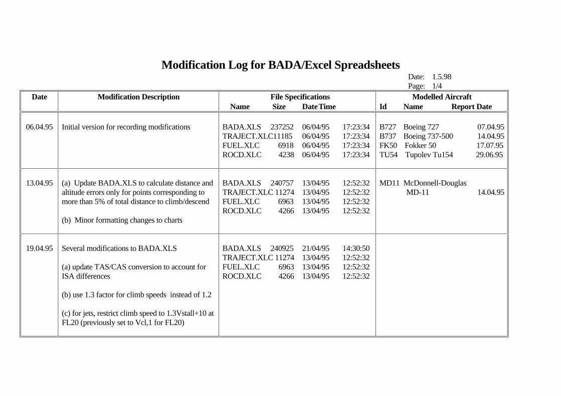
Modification Log for BADA/Excel SpreadsheetsDate: 1.5.98Page: 1/4
Date Modification Description File Specifications Name Size DateTime
Modelled AircraftId Name Report Date
06.04.95 Initial version for recording modifications BADA.XLS 237252 06/04/95 17:23:34TRAJECT.XLC11185 06/04/95 17:23:34FUEL.XLC 6918 06/04/95 17:23:34ROCD.XLC 4238 06/04/95 17:23:34
B727 Boeing 727 07.04.95B737 Boeing 737-500 14.04.95FK50 Fokker 50 17.07.95TU54 Tupolev Tu154 29.06.95
13.04.95 (a) Update BADA.XLS to calculate distance andaltitude errors only for points corresponding to more than 5% of total distance to climb/descend
(b) Minor formatting changes to charts
BADA.XLS 240757 13/04/95 12:52:32TRAJECT.XLC 11274 13/04/95 12:52:32FUEL.XLC 6963 13/04/95 12:52:32ROCD.XLC 4266 13/04/95 12:52:32
MD11 McDonnell-Douglas MD-11 14.04.95
19.04.95 Several modifications to BADA.XLS
(a) update TAS/CAS conversion to account forISA differences
(b) use 1.3 factor for climb speeds instead of 1.2
(c) for jets, restrict climb speed to 1.3Vstall+10 atFL20 (previously set to Vcl,1 for FL20)
BADA.XLS 240925 21/04/95 14:30:50TRAJECT.XLC 11274 13/04/95 12:52:32FUEL.XLC 6963 13/04/95 12:52:32ROCD.XLC 4266 13/04/95 12:52:32
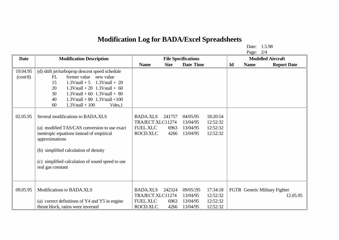
Modification Log for BADA/Excel SpreadsheetsDate: 1.5.98Page: 2/4
Date Modification Description File Specifications Name Size Date Time
Modelled AircraftId Name Report Date
19.04.95(cont’d)
(d) shift jet/turboprop descent speed scheduleFL former value new value15 1.3Vstall + 5 1.3Vstall + 2020 1.3Vstall + 20 1.3Vstall + 6030 1.3Vstall + 60 1.3Vstall + 8040 1.3Vstall + 80 1.3Vstall +10060 1.3Vstall + 100 Vdes,1
02.05.95 Several modifications to BADA.XLS
(a) modified TAS/CAS conversion to use exactisentropic equations instead of empiricalapproximations
(b) simplified calculation of density
(c) simplified calculation of sound speed to usereal gas constant
BADA.XLS 241757 04/05/95 18:20:54TRAJECT.XLC11274 13/04/95 12:52:32FUEL.XLC 6963 13/04/95 12:52:32ROCD.XLC 4266 13/04/95 12:52:32
09.05.95 Modifications to BADA.XLS
(a) correct definitions of Y4 and Y5 in enginethrust block, ratios were inversed
BADA.XLS 242324 09/05/;95 17:34:18TRAJECT.XLC11274 13/04/95 12:52:32FUEL.XLC 6963 13/04/95 12:52:32ROCD.XLC 4266 13/04/95 12:52:32
FGTR Generic Military Fighter 12.05.95
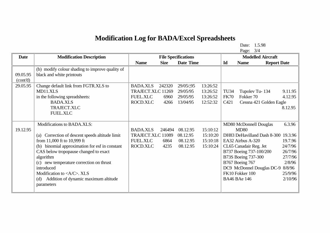
Modification Log for BADA/Excel SpreadsheetsDate: 1.5.98Page: 3/4
Date Modification Description File Specifications Name Size Date Time
Modelled AircraftId Name Report Date
09.05.95(cont’d)
(b) modify colour shading to improve quality ofblack and white printouts
29.05.95 Change default link from FGTR.XLS toMD11.XLSin the following spreadsheets:
BADA.XLSTRAJECT.XLCFUEL.XLC
BADA.XLS 242320 29/05/;95 13:26:52TRAJECT.XLC 11269 29/05/95 13:26:52FUEL.XLC 6960 29/05/95 13:26:52ROCD.XLC 4266 13/04/95 12:52:32
TU34 Tupolev Tu- 134 9.11.95FK70 Fokker 70 4.12.95C421 Cessna 421 Golden Eagle 8.12.95
19.12.95 Modifications to BADA.XLS:
(a) Correction of descent speeds altitude limitfrom 11,000 ft to 10,999 ft(b) binomial approximation for esf in constantCAS below tropopause changed to exactalgorithm(c) new temperature correction on thrustintroducedModification to <A/C>. XLS(d) Addition of dynamic maximum altitudeparameters
BADA.XLS 246494 08.12.95 15:10:12TRAJECT.XLC 11089 08.12.95 15:10:20FUEL.XLC 6864 08.12.95 15:10:18ROCD.XLC 4235 08.12.95 15:10:24
MD80 McDonnell Douglas 6.3.96 MD80 DH83 DeHavilland Dash 8-300 19.3.96EA32 Airbus A-320 19.7.96CL65 Canadair Reg. Jet 24/7/96B737 Boeing 737-100/200 26/7/96B73S Boeing 737-300 27/7/96B767 Boeing 767 2/8/96DC9 McDonnel Douglas DC-9 8/8/96FK10 Fokker 100 25/9/96BA46 BAe 146 2/10/96
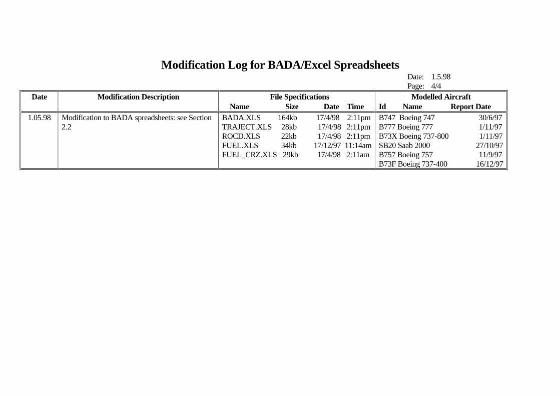
Modification Log for BADA/Excel SpreadsheetsDate: 1.5.98Page: 4/4
Date Modification Description File Specifications Name Size Date Time
Modelled AircraftId Name Report Date
1.05.98 Modification to BADA spreadsheets: see Section2.2
BADA.XLS 164kb 17/4/98 2:11pmTRAJECT.XLS 28kb 17/4/98 2:11pmROCD.XLS 22kb 17/4/98 2:11pmFUEL.XLS 34kb 17/12/97 11:14amFUEL_CRZ.XLS 29kb 17/4/98 2:11am
B747 Boeing 747 30/6/97B777 Boeing 777 1/11/97B73X Boeing 737-800 1/11/97SB20 Saab 2000 27/10/97B757 Boeing 757 11/9/97B73F Boeing 737-400 16/12/97
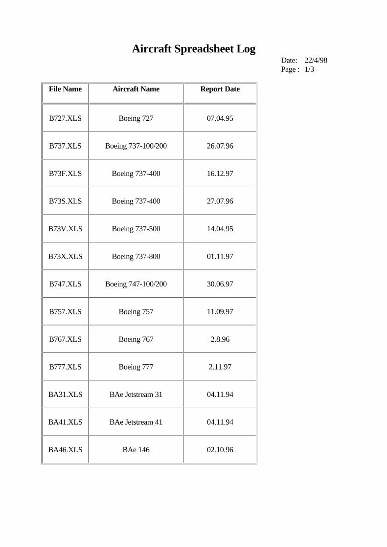
Aircraft Spreadsheet LogDate: 22/4/98Page : 1/3
File Name Aircraft Name Report Date
B727.XLS Boeing 727 07.04.95
B737.XLS Boeing 737-100/200 26.07.96
B73F.XLS Boeing 737-400 16.12.97
B73S.XLS Boeing 737-400 27.07.96
B73V.XLS Boeing 737-500 14.04.95
B73X.XLS Boeing 737-800 01.11.97
B747.XLS Boeing 747-100/200 30.06.97
B757.XLS Boeing 757 11.09.97
B767.XLS Boeing 767 2.8.96
B777.XLS Boeing 777 2.11.97
BA31.XLS BAe Jetstream 31 04.11.94
BA41.XLS BAe Jetstream 41 04.11.94
BA46.XLS BAe 146 02.10.96

Aircraft Spreadsheet LogDate: 22/4/98Page : 2/3
File Name Aircraft Name Report Date
BATP.XLS BAe Advanced Turboprop 19.11.94
C421.XLS Cessna 421 Golden Eagle 8.12.95
CL65.XLS Canadair Regional Jet 24.07.96
D228.XLS Dornier 228 26.01.95
D328.XLS Dornier 328 17.02.95
DC9.XLS McDonnell-Douglas DC-9 08.08.96
DH83.XLS DeHavilland Dash 8-300 19.03.96
EA32.XLS Airbus A-320 19.07.96
FGTR.XLS Generic Military Fighter 12.05.95
FK10.XLS Fokker 100 25.09.96
FK50.XLS Fokker 50 17.07.95
FK70.XLS Fokker 70 04.14.95
MD80.XLS McDonnell-Douglas MD-80 06.03.96
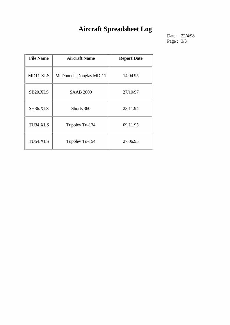
Aircraft Spreadsheet LogDate: 22/4/98Page : 3/3
File Name Aircraft Name Report Date
MD11.XLS McDonnell-Douglas MD-11 14.04.95
SB20.XLS SAAB 2000 27/10/97
SH36.XLS Shorts 360 23.11.94
TU34.XLS Tupolev Tu-134 09.11.95
TU54.XLS Tupolev Tu-154 27.06.95