EUR FREQUENCY MANAGEMENT MANUAL and NAT Documents/EUR...EUR Frequency Management Manual – ivICAO...
102
EUR Doc 011 INTERNATIONAL CIVIL AVIATION ORGANIZATION EUROPEAN AND NORTH ATLANTIC OFFICE EUR FREQUENCY MANAGEMENT MANUAL for Aeronautical Mobile and Aeronautical Radio Navigation Services Edition December 2019
Transcript of EUR FREQUENCY MANAGEMENT MANUAL and NAT Documents/EUR...EUR Frequency Management Manual – ivICAO...
EUR Doc 011
INTERNATIONAL CIVIL AVIATION ORGANIZATION
EUROPEAN AND NORTH ATLANTIC OFFICE
EUR FREQUENCY MANAGEMENT MANUAL
for
Aeronautical Mobile
and
Aeronautical Radio Navigation
Services
Edition December 2019
EUR Frequency Management Manual – ICAO EUR Doc 011 (2019) ii
AMENDMENTS
Procedure for the Amendment of the EUR Frequency Management Manual
Principles and procedures for the amendment of EUR Documents, as approved by EANPG, are
contained in the EANPG Handbook, EUR Doc 001. Accordingly, amendments to the EUR Frequency
Management Manual which have been approved by the FMG are formally endorsed by EANPG
and/or COG. Amendments to the EUR Frequency Management Manual shall be effected on the basis
of an adequately documented proposal submitted to the FMG of the EANPG. Such proposals should
include draft new text clearly identifying additions, modifications and deletions of existing text.
The latest edition of this Manual, including endorsed amendments, will be promulgated to FMG
members by the ICAO Regional Office and access will be provided at the ICAO Website.
INTERNATIONAL CIVIL AVIATION ORGANIZATION
European and North Atlantic Office
Web http://www.icao.int/EURNAT/
E-mail [email protected]
Tel +33 1 46 41 85 85
Fax +33 1 46 41 85 00
Mail 3 bis Villa Emile Bergerat
F-92522 Neuilly-sur-Seine Cedex
France
Edition Subject(s) Approved
2002 Introduction of EUR Frequency Management Manual FMG/6
2003 Amendment of criteria for 3rd
adjacent 8.33 kHz COM channel;
Addition of note on COM offset-carrier systems;
Addition of note on extension of ILS Glide Path up to 15 NM;
Amendment of DME planning criteria for different pulse code;
and
Amendment of planning criteria for identifications of radio
navigation aids.
FMG/7
2004 Amendment concerning VDL and 8.33 kHz for OPC;
Amendment concerning VHF COM area to broadcast services
separation distance;
Amendment concerning NDB frequency co-ordination above
526.5 kHz;
Amendment of GBAS VDB provisions; and
Amendment of planning criteria for identifications according to
Annex 11.
FMG/8
2005 Amendment concerning ILS frequency assignment planning;
Addition of note concerning VHF COM vertical separation;
Addition of Block Planning Rules (Appendix to Part II); and
Addition of offset carrier (CLIMAX) information.
FMG/9
2006 Amendment concerning temporary guidance for GBAS/H
planning criteria,
Amendment concerning temporary use of ILS to GBAS planning
co-ordination criteria,
Amendment concerning GBAS VDB frequency planning
assignment criteria,
Amendment concerning Block Planning procedure
FMG/10
EUR Frequency Management Manual – ICAO EUR Doc 011 (2019) iii
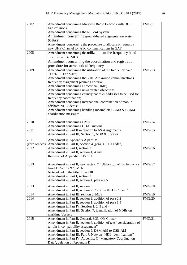
2007 Amendment concerning Maritime Radio Beacons with DGPS
transmissions
Amendment concerning the RSBN4 System
Amendment concerning ground-based augmentation system
(GBAS)
Amendment concerning the procedure to allocate or request a
new UHF Channel for ATC communications in GAT
FMG/11
2008 Amendment concerning the utilization of the frequency band
117.975 – 137 MHz
Amendment concerning the coordination and registration
procedure for aeronautical frequency
2009
Amendment concerning the utilization of the frequency band
117.975 – 137 MHz;
Amendment concerning the VHF AirGround communications
frequency assignment planning criteria;
Amendment concerning Directional DME;
Amendment concerning unwarranted objections;
Amendment concerning country codes & addresses to be used for
frequency coordination;
Amendment concerning international coordination of mobile
offshore NDB idents;
Amendment concerning handling incomplete COM3 & COM4
coordination messages.
FMG/13
2010 Amendment concerning DME.
Amendment concerning GBAS material
FMG/14
2011
2011
(corrigended)
Amendment in Part II in relation to AS Assignments
Amendment in Part III, Section 1, NDB & Locator
Amendment in Appendix A part IV
Amendment in Part II, Section 4 (para. 4.1.1.1 added)
FMG/15
2012 Amendment in Part I, section 3
Amendment in Part II, section 1, 4 and 5
Removal of Appendix in Part II
FMG/16
2013 Amendment in Part II, new section 7 “Utilization of the frequency
band 112 – 117.975 MHz
Note added to the title of Part III
Amendment in Part I, section 3
Amendment in Part II, section 4, para 4.2.5
FMG/17
2013 Amendment in Part II, section 5
Amendment in Part II, section 2 , “8.33 in the OPC band”
FMG/18
2014 Amendment in Part III, section 3, MLS FMG/19
2014
Amendment in Part II, section 2, addition of para 2.2
Amendment in Part II, section 1, addition of para 1.9
Amendment in Part IV, Section 1, 2, 3 and 4
Amendment in Part III, Section 7, identification of NDBs on
maritime Vessels
FMG/20
2015 Amendment in Part II, General, 8.33 kHz Climax
Amendment in Part II, section 4, addition of text “consideration of
terrain in compatibility assessment”
Amendment in Part II, section 5, DSM-AM to DSB-AM
Amendment in Part III, Part 7, Note on “NDB identifications”
Amendment in Part IV, Appendix C “Mandatory Coordination
Data”, deletion of Appendix D
FMG/21
EUR Frequency Management Manual – ICAO EUR Doc 011 (2019) iv
2016 Amendment in Part II, Section 2, utilization of frequency band
117.975-137 MHz
FMG/22
Amendment in Part II, Section 3 and 4
Amendments in Part II, Section 7, Utilization of the Frequency
band 112 – 117.975 MHz
Amendment in Part II, addition of section 8 “VDL Mode 2
Assignments”
Amendment in Part III, Section 1, NDB
Amendment in Part III, Section 3, Addition of Note in Para 3.1.1
Amendment in Part III, Section 5, DME
Amendment to the Supplement of EUR Doc 011, Insertion of
section “B. Guidance on the Coordination of Common
Assignments”
2017 Amendment in Part II, Section 1
Amendment in Part II, Section 3 and Section 8
Amendment in Part III, Section 2, ILS Frequency Assignment
Planning Criteria
Amendment in Part III, Section 5, DME
Editorial Updates in Part III, Section 1
Amendment to the Supplement of EUR Doc 011, Insertion of
section F “VDL Ground Station Installation Guidance”
FMG/23
2018 Amendment List of Abbreviations and Part I, General Overview
Amendment Part II, Section 1, Pilot Controlled Lighting
Amendment Part II, Add Section 9, VLD Mode 4 Assignements
Amendment part III, Section 5, DME
Amendment part III, Section 4, GBAS
Amendment to the Supplement of EUR Doc 011:
Addition of Guidance on DME First Adjacent-Channel
Compatibility
Addition Section D ‘Prioritisation Method for DME
Channels’
FMG/24
2019 Amendment Part III, Section 3, VOR
Amendment Part III, Section 7, Identification of Radio Navigation
Aids, deletion of a note
Amendment to Appendix A to Part III
Updates for Spain in Appendix A “Country Codes and AFTN
Addresses”
Amendment to the Supplement of EUR Doc 011:
Amendment in Part A Section 2.2
Addition of Part I : “Convention for Indicating the angular
limits of sectorization in range”, old method.
FMG/25
EUR Frequency Management Manual – ICAO EUR Doc 011 (2019) v
TABLE OF CONTENTS
AMENDMENTS ...................................................................................................................................................................... ii
LIST OF ABBREVIATIONS ................................................................................................................................................ vii
PART I SCOPE AND GENERAL OVERVIEW ............................................................................................................ 1
1 Scope ............................................................................................................................................................................... 1
2 The Frequency Management Group ............................................................................................................................ 2
3 General Rules for Co-ordination of Frequency Assignments .................................................................................... 3
PART II VHF AIR-GROUND COMMUNICATIONS FREQUENCY ASSIGNMENT PLANNING CRITERIA ... 5
1 General ........................................................................................................................................................................... 5
2 Utilization of the frequency band 117.975 – 137 MHz ................................................................................................ 7
3 Services and frequency protection volumes ................................................................................................................. 9
4 Co-channel separation distances between services .................................................................................................... 11
5 Adjacent channel separation distances between services ......................................................................................... 15
6 Operational Control .................................................................................................................................................... 17
7 Utilization of the Frequency Band 112 – 117.975 MHz ............................................................................................ 17
8 VDL Mode 2 Assignments ........................................................................................................................................... 19
9 VDL Mode 4 Assignments ........................................................................................................................................... 19
PART III RADIO NAVIGATION AID FREQUENCY ASSIGNMENT PLANNING CRITERIA ...................... 20
1 NDB and locator .......................................................................................................................................................... 20
2 ILS................................................................................................................................................................................. 30
3 VOR .............................................................................................................................................................................. 37
4 GBAS ............................................................................................................................................................................ 49
5 DME .............................................................................................................................................................................. 59
6 MLS .............................................................................................................................................................................. 75
7 Identifications of Radio Navigation Aids ................................................................................................................... 76
8. Non-ICAO Standard Systems operating in Part or in Total within ARNS Bands ................................................. 78
PART IV FREQUENCY CO-ORDINATION AND REGISTRATION PROCEDURES ............................................ 84
1 Introduction ................................................................................................................................................................. 84
2 General ......................................................................................................................................................................... 84
3 Basic Co-ordination and Registration Procedures for Aeronautical Frequency Assignments .............................. 85
EUR Frequency Management Manual – ICAO EUR Doc 011 (2019) vi
4 Procedure to allocate or request a New UHF Channel for ATC Communications in GAT .................................. 94
EUR Frequency Management Manual – ICAO EUR Doc 011 (2019) vii
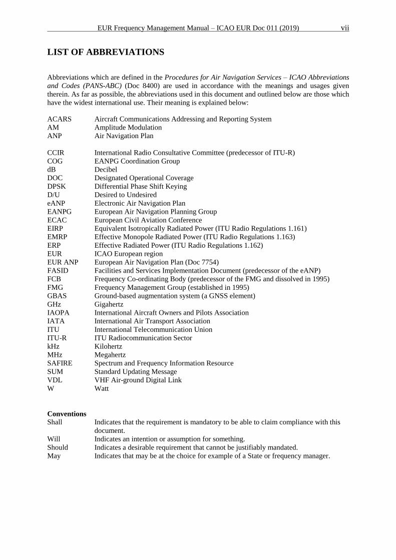
LIST OF ABBREVIATIONS
Abbreviations which are defined in the Procedures for Air Navigation Services – ICAO Abbreviations
and Codes (PANS-ABC) (Doc 8400) are used in accordance with the meanings and usages given
therein. As far as possible, the abbreviations used in this document and outlined below are those which
have the widest international use. Their meaning is explained below:
ACARS Aircraft Communications Addressing and Reporting System
AM Amplitude Modulation
ANP Air Navigation Plan
CCIR International Radio Consultative Committee (predecessor of ITU-R)
COG EANPG Coordination Group
dB Decibel
DOC Designated Operational Coverage
DPSK Differential Phase Shift Keying
D/U Desired to Undesired
eANP Electronic Air Navigation Plan
EANPG European Air Navigation Planning Group
ECAC European Civil Aviation Conference
EIRP Equivalent Isotropically Radiated Power (ITU Radio Regulations 1.161)
EMRP Effective Monopole Radiated Power (ITU Radio Regulations 1.163)
ERP Effective Radiated Power (ITU Radio Regulations 1.162)
EUR ICAO European region
EUR ANP European Air Navigation Plan (Doc 7754)
FASID Facilities and Services Implementation Document (predecessor of the eANP)
FCB Frequency Co-ordinating Body (predecessor of the FMG and dissolved in 1995)
FMG Frequency Management Group (established in 1995)
GBAS Ground-based augmentation system (a GNSS element)
GHz Gigahertz
IAOPA International Aircraft Owners and Pilots Association
IATA International Air Transport Association
ITU International Telecommunication Union
ITU-R ITU Radiocommunication Sector
kHz Kilohertz
MHz Megahertz
SAFIRE Spectrum and Frequency Information Resource
SUM Standard Updating Message
VDL VHF Air-ground Digital Link
W Watt
Conventions
Shall Indicates that the requirement is mandatory to be able to claim compliance with this
document.
Will Indicates an intention or assumption for something.
Should Indicates a desirable requirement that cannot be justifiably mandated.
May Indicates that may be at the choice for example of a State or frequency manager.
EUR Frequency Management Manual – ICAO EUR Doc 011 (2019) 1
_________________________________________________________________________________________________________________ PART I SCOPE AND GENERAL OVERVIEW
PART I SCOPE AND GENERAL OVERVIEW
1 Scope
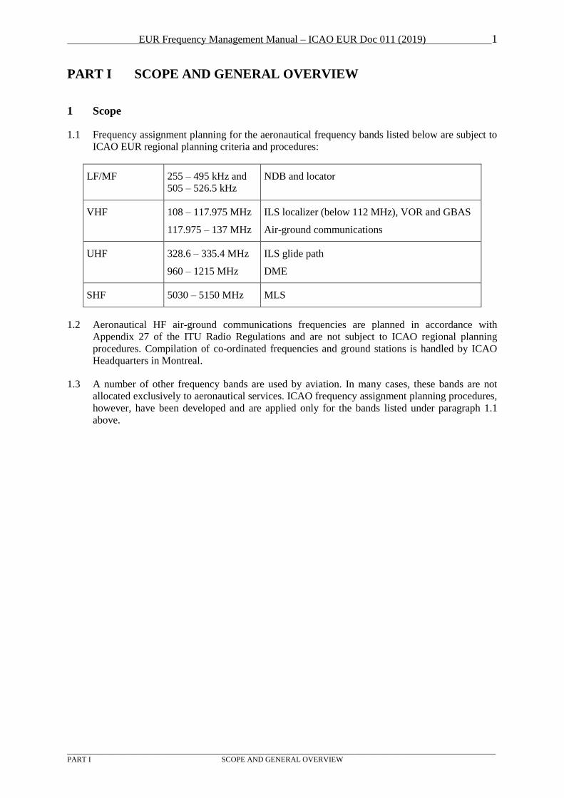
1.1 Frequency assignment planning for the aeronautical frequency bands listed below are subject to
ICAO EUR regional planning criteria and procedures:
LF/MF 255 – 495 kHz and
505 – 526.5 kHz
NDB and locator
VHF 108 – 117.975 MHz
117.975 – 137 MHz
ILS localizer (below 112 MHz), VOR and GBAS
Air-ground communications
UHF 328.6 – 335.4 MHz
960 – 1215 MHz
ILS glide path
DME
SHF 5030 – 5150 MHz MLS
1.2 Aeronautical HF air-ground communications frequencies are planned in accordance with
Appendix 27 of the ITU Radio Regulations and are not subject to ICAO regional planning
procedures. Compilation of co-ordinated frequencies and ground stations is handled by ICAO
Headquarters in Montreal.
1.3 A number of other frequency bands are used by aviation. In many cases, these bands are not
allocated exclusively to aeronautical services. ICAO frequency assignment planning procedures,
however, have been developed and are applied only for the bands listed under paragraph 1.1
above.
EUR Frequency Management Manual – ICAO EUR Doc 011 (2019) 2
_________________________________________________________________________________________________________________ PART I SCOPE AND GENERAL OVERVIEW
2 The Frequency Management Group
2.1 The Frequency Management Group (FMG) is established by EANPG Decision 37/2 to
pursue the tasks of the Group in the field of aeronautical frequency spectrum management in
support to the relevant ICAO Strategic Objectives with the following TORs:
a) Ensure the continuous and coherent development of the relevant sections of the European
eANP and other relevant regional documents, including EUR Doc 011 Frequency
Management Manual, taking into account the evolving operational requirements in the
EUR Region and the need for harmonization with the adjacent regions in compliance
with the Global Air Navigation Plan;
b) Monitor and coordinate implementation of the relevant ICAO SARPs and regional
procedures, facilities and services by the EUR States and where necessary promote and
facilitate harmonization, taking due account of financial and institutional issues;
c) Identify any deficiencies in the aeronautical frequency spectrum management related
matters in the EUR Region and coordinate the development and implementation of
relevant action plans by the States to resolve them;
d) Foster implementation by facilitating the exchange of know-how and transfer of
knowledge and experience among States of the Region;
e) Provide input to the work of appropriate ICAO bodies in the field of aeronautical
frequency spectrum, according to the established procedures.
2.2 The main tasks of the FMG are:
a) to establish co-ordinated frequency assignment plans for the EUR aeronautical mobile
services and the EUR radio navigation aids service, and to make recommendations, as
necessary, concerning frequency aspects of their implementation;
b) to co-ordinate the frequency aspects of new requirements, as necessary;
c) to give advice to States on questions of frequency assignment, rated coverage, etc., as
necessary;
d) to undertake specific tasks assigned to it by the EANPG;
e) to advise the EANPG on frequency spectrum issues covering all aeronautical radio
services, including satellite based facilities; and
f) to work in liaison with relevant international organisations.
2.3 Each State within the region and relevant international organisations such as
EUROCONTROL, IATA and IAOPA should nominate a FMG Member, being authorised
with the responsibility for aeronautical frequency management. In order to take care of
possible problems in the border area between Regions, the EUR FMG also includes experts
from States adjacent to the European Region, in practice the States along the Mediterranean.
Contact details can be found in a "List of FMG members and frequency experts" published
by the ICAO Paris office.
EUR Frequency Management Manual – ICAO EUR Doc 011 (2019) 3
_________________________________________________________________________________________________________________ PART I SCOPE AND GENERAL OVERVIEW
3 General Rules for Co-ordination of Frequency Assignments
3.1 Chapters 4 and 5 of Volume I of the ICAO “Handbook on Radio Frequency Spectrum
Requirements for Civil Aviation” (Doc 9718) provide an overview of institutional relations
important to aeronautical frequency management and co-ordination of assignments.
3.2 In most cases a Telecommunications Administration / Radio Authority within a State is the
responsible superior authority for use of the radio spectrum. This includes the authority to co-
ordinate new assignments with other States under the rules of the ITU and after successful co-
ordination to register the new assignment.
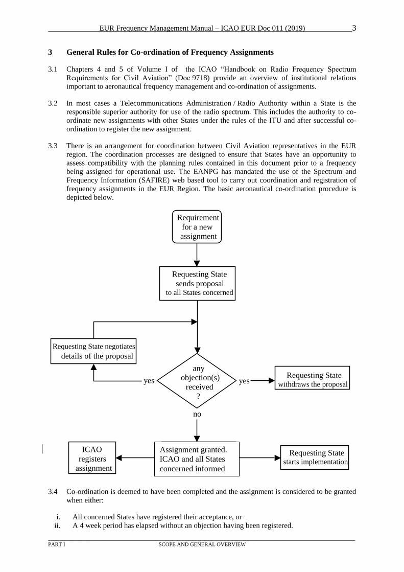
3.3 There is an arrangement for coordination between Civil Aviation representatives in the EUR
region. The coordination processes are designed to ensure that States have an opportunity to
assess compatibility with the planning rules contained in this document prior to a frequency
being assigned for operational use. The EANPG has mandated the use of the Spectrum and
Frequency Information (SAFIRE) web based tool to carry out coordination and registration of
frequency assignments in the EUR Region. The basic aeronautical co-ordination procedure is
depicted below.
3.4 Co-ordination is deemed to have been completed and the assignment is considered to be granted
when either:
i. All concerned States have registered their acceptance, or
ii. A 4 week period has elapsed without an objection having been registered.
Requesting State
sends proposal to all States concerned
Requesting State negotiates
details of the proposal
Requesting State withdraws the proposal
Requesting State sends
SUM to ICAO and all
States concerned
ICAO
registers
assignment
Requesting State starts implementation
any
objection(s)
received
?
Requirement
for a new
assignment
yes
no
yes
Assignment granted.
ICAO and all States
concerned informed
EUR Frequency Management Manual – ICAO EUR Doc 011 (2019) 4
_________________________________________________________________________________________________________________ PART I SCOPE AND GENERAL OVERVIEW
3.5 For the VHF communications band 117.975 - 137 MHz special procedures are applied due to
the congestion problems in this band. Block Planning Exercises are organised, as required,
based on the mutual arrangements agreed between the States involved. These exercises are
organized for those requirements for which an available channel can only be identified through
shifting of one or more existing assignments to some other channel. The normal coordination
procedure can be used if no shifts are involved.
3.6 Co-ordination must be made with all States that in some way may be affected by the proposed
assignment. Additionally some States may have an interest in being informed about changes,
although not directly affecting them, in order to update national databases or for other purposes.
3.7 After successful co-ordination of a new or modified assignment, the assignment is registered in
SAFIRE database. All States and ICAO are informed about the registration of assignments
through SAFIRE. The registered assignments are published in the appropriate frequency
assignment table of the ICAO EUR Air Navigation Plan.
EUR Frequency Management Manual – ICAO EUR Doc 011 (2019) 5
_________________________________________________________________________________________________________________
PART II RADIO NAVIGATION AID FREQUENCY ASSIGNMENT PLANNING CRITERIA
PART II VHF AIR-GROUND COMMUNICATIONS FREQUENCY
ASSIGNMENT PLANNING CRITERIA
1 General
1.1 The band 117.975 - 137 MHz is allocated to the aeronautical mobile (R) service and used
mainly for air/ground voice communications and, to some extent, air/ground data
communications.
1.2 References to documents:
- Annex 10, Volume V, paragraph 4.1
(allotment table, channelling, protection criteria);
- Annex 10, Attachment A to Volume V
(protection criteria, calculations, propagation curves);
- European Region Air Navigation Plan (Doc 7754), Volume I, Basic ANP, Part IV,
paragraphs 25, 28-30, 33-41
(136-137 MHz, communications for ATS, uniform designated operational coverage,
frequency assignment planning).
- European Region Air Navigation Plan (Doc 7754), Volume II, FASID, Part IV, paragraphs
11, 18-21
(tables of requirements, co-existence of different channel spacing, sector combinations).
1.3 Depending on the type of service, the protected range can be from 16 NM to 260 NM or defined
by the border of a FIR or sector. The protected altitude can vary from 3000 ft up to 45000 ft.
The actual protection details can be obtained from the frequency assignment table.
1.3.1 Protection by distance separation has in the past been achieved by making sure that any other
transmitter (on the ground or airborne) is below the radio horizon. Alternatively, a recently
introduced change to Annex 10 allows the Regional use of a desired to undesired signal ratio of
14 dB, equivalent to a 5 to 1 distance ratio, if this separation distance is shorter than the distance
to the radio horizon.
1.3.2 Risk of conflict normally only occurs between two aircraft, one in each service area, while the
location of the ground transmitter is of less importance. For practical planning special software
made available through EUROCONTROL or a table may be used, listing the required distance
between combinations of services on the same channel. Also the adjacent channel is considered.
1.3.3 Some sub-bands are reserved for special purposes. From 121.5417 to 121.9917 MHz only
ground-ground communication is allowed, typically for communications between the TWR and
taxiing aircraft. The bands 131.400 to 131.975 MHz is used by airlines for OPC according to
special rules. In several States, common frequencies are used for applications such as light
aviation, gliding and ballooning activities, etc.
1.3.3.1 Frequency assignment should be done in the dedicated sub-bands. Due to the limitations of the
sub-bands, States are strongly encouraged to introduce 8.33 kHz channel spacing to reduce
frequency congestion.
1.3.3.2 It is recommended that States reduce the antenna height and transmit power to reduce the
possibility of interference to other stations, but still be able to provide sufficient coverage.
1.3.3.3 In case of congestion of the dedicated AS sub-band, frequencies may be planned on a
temporary basis outside the sub-band in accordance with the planning criteria.

EUR Frequency Management Manual – ICAO EUR Doc 011 (2019) 6
_________________________________________________________________________________________________________________
PART II RADIO NAVIGATION AID FREQUENCY ASSIGNMENT PLANNING CRITERIA
1.3.4 Three channels are used for ACARS which is not an ICAO system. The uppermost part of the
VHF COM band (136.700 – 136.975 MHz) is reserved for VDL Mode 2 and VDL Mode 4.
1.3.5 Frequency assignments can be reserved for a common use over several States. Guidance
material on the allotment, coordination and compatibility assessment between common
assignments is provided in the Supplement to EUR Doc011.
1.4 The risk of interference from broadcasting stations in the band 87 - 108 MHz, due to
interference caused by unwanted emissions into the aeronautical band or generated in the
airborne receiver, is generally not considered to be an operational problem for this type of
communications.
1.5 Co-ordination must at least be made with States which may be affected by the proposal. Special
care is required for assignments with a very large co-ordination distance (e.g. VOLMET) which
may exist on almost any frequency in the band.
1.6 It has been agreed within the FMG to use a special procedure due to the congestion problems in
this band. Requests for assignments which cannot be satisfied without shifts have to be
submitted to a Block Planning exercise , which is run about every six months and based on the
mutual arrangements agreed between the States involved.
1.7 Call signs and designators are not considered as part of the frequency planning process in this
band.
1.8 The ICAO planning criteria presented in this document do not provide protection against
interference phenomena which may occur if communication facilities are co-located (e.g.
interference caused by intermodulation). It is therefore possible that a proposed frequency is not
acceptable due to specific local conditions.
1.9 8.33 kHz CLIMAX. Significant numbers of aircraft currently operating in European airspace are
believed not to be equipped with radios intended for 8.33 kHz offset carrier operation.
Consequently,the assignment of 8.33 kHz channels for operation in offset carrier mode shall not
be permitted until further notice, whilst studies are conducted, except in cases where all aircraft
receiving the service are equipped with a radio intended for 8.33 kHz offset carrier operation.
Note: Aircraft radios intended for 8.33 kHz offset carrier operation should be compliant
with the requirements for EUROCAE ED-23C Class H1 or H2 receivers.
1.10 EANPG Conclusion 56/04 invites States to permit the use of TWR frequencies by vehicles
involved in runway operations, where required:
Note: Any assignment of a TWR frequency to vehicles involved in runway operation should be
subject to local safety assessment. Such assessment should address in particular training,
operating procedures and the use of one language in radiotelephony communications between
air crews, vehicle drivers and TWR controllers, and enforcement measures.
1.11 At aerodromes where a VHF pilot-controlled lighting systems are deployed, these should
generally operate on the frequency assigned to the aerodrome. No separate frequency should be
required.
1.12 Assignment of VHF Data Link (VDL) services. States shall only coordinate and assign VDL
Mode 2 and 4 frequencies approved by the FMG and contained in the VHF data link channel
plan.
EUR Frequency Management Manual – ICAO EUR Doc 011 (2019) 7
_________________________________________________________________________________________________________________
PART II RADIO NAVIGATION AID FREQUENCY ASSIGNMENT PLANNING CRITERIA
2 Utilization of the frequency band 117.975 – 137 MHz
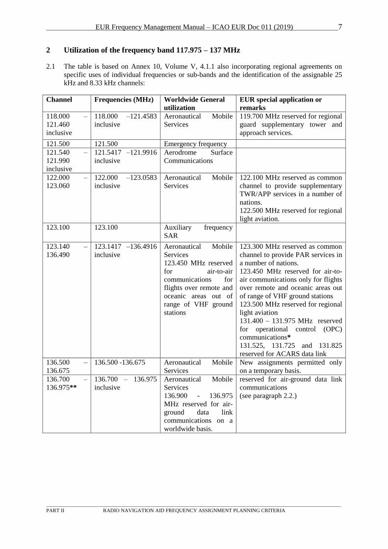
2.1 The table is based on Annex 10, Volume V, 4.1.1 also incorporating regional agreements on
specific uses of individual frequencies or sub-bands and the identification of the assignable 25
kHz and 8.33 kHz channels:
Channel Frequencies (MHz) Worldwide General
utilization
EUR special application or
remarks
118.000 –
121.460
inclusive
118.000 –121.4583
inclusive
Aeronautical Mobile
Services
119.700 MHz reserved for regional
guard supplementary tower and
approach services.
121.500 121.500 Emergency frequency
121.540 –
121.990
inclusive
121.5417 –121.9916
inclusive
Aerodrome Surface
Communications
122.000 –
123.060
122.000 –123.0583
inclusive
Aeronautical Mobile
Services
122.100 MHz reserved as common
channel to provide supplementary
TWR/APP services in a number of
nations.
122.500 MHz reserved for regional
light aviation.
123.100 123.100 Auxiliary frequency
SAR
123.140 –
136.490
123.1417 –136.4916
inclusive
Aeronautical Mobile
Services
123.450 MHz reserved
for air-to-air
communications for
flights over remote and
oceanic areas out of
range of VHF ground
stations
123.300 MHz reserved as common
channel to provide PAR services in
a number of nations.
123.450 MHz reserved for air-to-
air communications only for flights
over remote and oceanic areas out
of range of VHF ground stations
123.500 MHz reserved for regional
light aviation
131.400 – 131.975 MHz reserved
for operational control (OPC)
communications*
131.525, 131.725 and 131.825
reserved for ACARS data link
136.500 –
136.675
136.500 -136.675 Aeronautical Mobile
Services
New assignments permitted only
on a temporary basis.
136.700 –
136.975**
136.700 – 136.975
inclusive
Aeronautical Mobile
Services
136.900 - 136.975
MHz reserved for air-
ground data link
communications on a
worldwide basis.
reserved for air-ground data link
communications
(see paragraph 2.2.)
EUR Frequency Management Manual – ICAO EUR Doc 011 (2019) 8
_________________________________________________________________________________________________________________
PART II RADIO NAVIGATION AID FREQUENCY ASSIGNMENT PLANNING CRITERIA
Guard bands:
For 121.500: Channels 121.475, and 121.525, are not assignable; and
For 123.100: Channels 123.065, 123.075, 123.080, 123.085, 123.115, 123.125, 123.130, and 123.135 are not assignable, except for ATIS on channels 123.080 and 123.130.
For VDL: Channels 136.700, 136.750, 136.800, 136.850, 136.900 and 136.950 are not assignable (FMG/6).
*OPC: Assignments used for OPC purposes shall not be co-ordinated on protected channels. 8.33 kHz channel spacing to be used
wherever possible, between 131.405 – 131.9801 except for the ACARS channels 131.525, 131.725 and 131.825. The use of voice
at the first adjacent 8,33KHz channel to ACARS is not possible. Care should be taken when considering the use of the second adjacent channel at 16,67 KHz from the ACARS.
Unprotected assignments within this band can accommodate services other than OPC, where local planning conditions permit.
Concerning the use for ATS purposes of the lower adjacent frequencies to 131.400 and the upper adjacent frequencies to 131.975,
care should be exercised for the observance of adjacent channel compatibility requirements.
**Note: 8.33 kHz channel spacing is not to be used for frequencies 136.500 – 136.975 MHz inclusive (Annex 10, Volume V, Note 1 to
paragraph 4.1.8.1.1).
1 The band 131.405 – 131.980 is suggested in accordance with the proposed definition on Unprotected assignments. (FMG22/WP11)
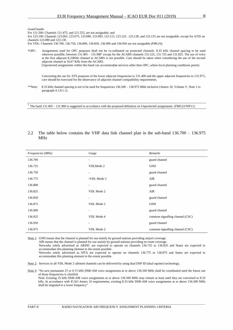
2.2 The table below contains the VHF data link channel plan in the sub-band 136.700 – 136.975
MHz
Frequencies (MHz) Usage Remarks
136.700 - guard channel
136.725 VDLMode 2 GND
136.750 - guard channel
136.775 -VDL Mode 2 AIR
136.800 - guard channel
136.825 VDL Mode 2 AIR
136.850 - guard channel
136.875 VDL Mode 2 GND
136.900 - guard channel
136.925 VDL Mode 4 common signalling channel (CSC)
136.950 - guard channel
136.975 VDL Mode 2 common signalling channel (CSC)
Note 1: GND means that the channel is planned for use mainly by ground stations providing airport coverage. AIR means that the channel is planned for use mainly by ground stations providing en-route coverage.
Networks solely advertised as ARINC are expected to operate on channels 136.725 or 136.825 and States are expected to
accommodate this planning element to the extent possible. Networks solely advertised as SITA are expected to operate on channels 136.775 or 136.875 and States are expected to
accommodate this planning element to the extent possible.
Note 2: Services in all VDL Mode 2-allotted channels can be delivered by using dual DSP ID (dual squitter) technology.
Note 3: “No new permanent 25 or 8.33 kHz DSB-AM voice assignments at or above 136.500 MHz shall be coordinated until the future use of those frequencies is clarified.
Note: Existing 25 kHz DSB-AM voice assignments at or above 136.500 MHz may remain at least until they are converted to 8.33
kHz. In accordance with ICAO Annex 10 requirements, existing 8.33 kHz DSB-AM voice assignments at or above 136.500 MHz shall be migrated to a lower frequency”
EUR Frequency Management Manual – ICAO EUR Doc 011 (2019) 9
_________________________________________________________________________________________________________________
PART II RADIO NAVIGATION AID FREQUENCY ASSIGNMENT PLANNING CRITERIA
3 Services and frequency protection volumes
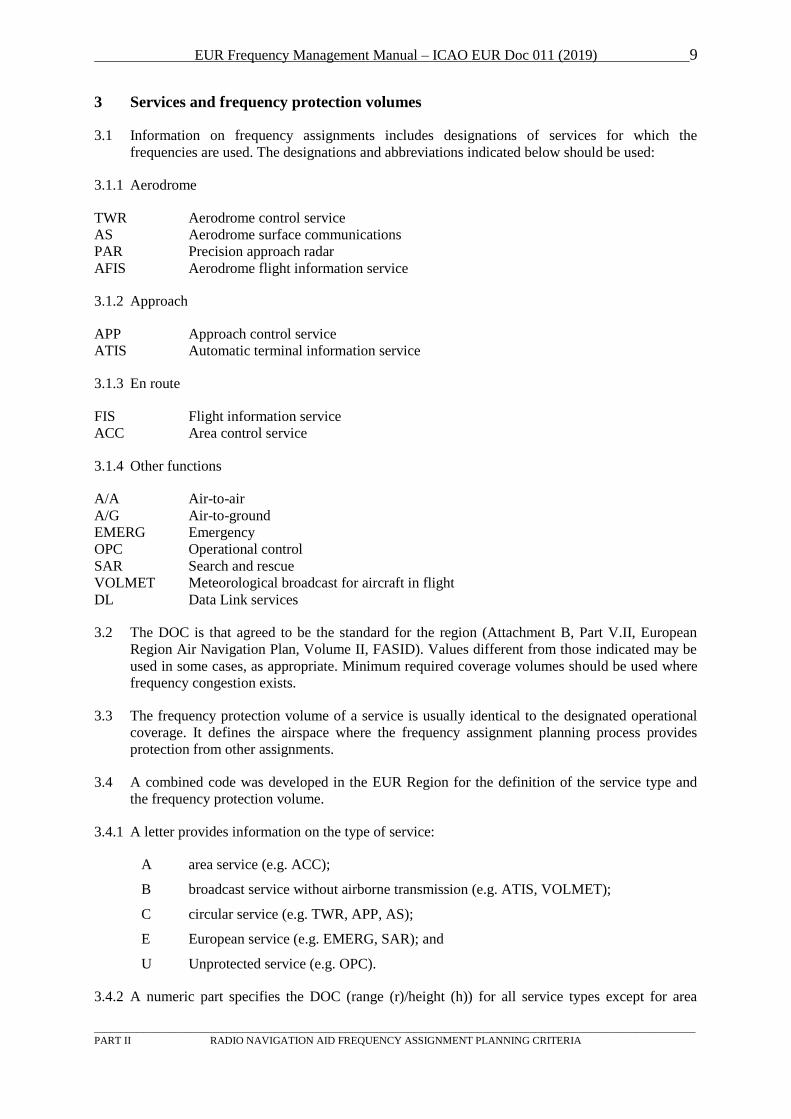
3.1 Information on frequency assignments includes designations of services for which the
frequencies are used. The designations and abbreviations indicated below should be used:
3.1.1 Aerodrome
TWR Aerodrome control service
AS Aerodrome surface communications
PAR Precision approach radar
AFIS Aerodrome flight information service
3.1.2 Approach
APP Approach control service
ATIS Automatic terminal information service
3.1.3 En route
FIS Flight information service
ACC Area control service
3.1.4 Other functions
A/A Air-to-air
A/G Air-to-ground
EMERG Emergency
OPC Operational control
SAR Search and rescue
VOLMET Meteorological broadcast for aircraft in flight
DL Data Link services
3.2 The DOC is that agreed to be the standard for the region (Attachment B, Part V.II, European
Region Air Navigation Plan, Volume II, FASID). Values different from those indicated may be
used in some cases, as appropriate. Minimum required coverage volumes should be used where
frequency congestion exists.
3.3 The frequency protection volume of a service is usually identical to the designated operational
coverage. It defines the airspace where the frequency assignment planning process provides
protection from other assignments.
3.4 A combined code was developed in the EUR Region for the definition of the service type and
the frequency protection volume.
3.4.1 A letter provides information on the type of service:
A area service (e.g. ACC);
B broadcast service without airborne transmission (e.g. ATIS, VOLMET);
C circular service (e.g. TWR, APP, AS);
E European service (e.g. EMERG, SAR); and
U Unprotected service (e.g. OPC).
3.4.2 A numeric part specifies the DOC (range (r)/height (h)) for all service types except for area
EUR Frequency Management Manual – ICAO EUR Doc 011 (2019) 10
_________________________________________________________________________________________________________________
PART II RADIO NAVIGATION AID FREQUENCY ASSIGNMENT PLANNING CRITERIA
services where the horizontal extension is defined as a polygon):
A-h the vertical extension is provided as an integer multiple of 100 ft (e.g. A-450 is used
for an area service with an upper limit at 45000 ft for sector Upper1);
B-r/h the horizontal circular extension is expressed in NM and the vertical extension in
integer multiples of 100 ft (e.g. B-60/200 is used for a broadcast service with a range
of 60 NM and a vertical extension of 20000 ft);
C-r/h as for B-r/h (e.g. C-40/150 is used for an approach service with a range of 40 NM and
a vertical extension of 15000 ft);
ICAO Table COM 2 contains a specific field to indicate whether an assignment has protected
or unprotected status. Unprotected services, such as OPC, are recorded in Table COM 2 with
the protection field set to “U”.
EUR Frequency Management Manual – ICAO EUR Doc 011 (2019) 11
_________________________________________________________________________________________________________________
PART II RADIO NAVIGATION AID FREQUENCY ASSIGNMENT PLANNING CRITERIA
4 Co-channel separation distances between services
DSM-AM TO DSB-AM
4.1 The following principles for VHF planning criteria for determining the separation distances
between RTF services with DSB AM carriers and 8.33 or 25 kHz channel spacing should be
used in the EUR region. Co-channel separation criteria should be applied between an 8.33 kHz
and a 25 kHz channel using the same frequency (co-frequency, e.g. channels 132.000 /
132.005).To protect a service with a circular operational coverage (circular service), the distance
from the edge of the service to another airborne or ground transmitter should be 5 times the
range of that circular service; if the other transmitter is below the radio horizon from that service
edge and the radio horizon distance is also less than 5 times the circular service range then radio
horizon distance should be used.
4.1.1 In order to ensure the appropriate frequency planning and assignment of circular services, it is
recommended that the operational coverage of circular services is such that the radius is in
appropriate proportion to the height (note : further work on this issue to be carried out).
4.1.2 To protect a service with a non-circular operational coverage area, the ground or airborne
transmitter of the other service should be below the radio horizon.
4.1.3 The protection criteria for both the requested service and the existing assignment should be met
for a valid assignment.
4.2 The following co-channel protection criteria should be used for planning purposes.
4.2.1 Circular service areas (except broadcast functions) should be planned so that the separation
distance from the edge of one circular service area to another circular service should be 5 times
the larger range from those respective DOCs or the sum of their radio horizon, whichever is
least.
4.2.2 The separation distance between circular and area services should be calculated using the radio
horizon method. The separation distance between the service edge of the two services should be
the sum of the two relevant radio horizon distances (radio line-of-sight distance).
4.2.3 The separation distance between circular and broadcast services should be determined as
follows:
a) the separation distance between the aircraft receiver at the circular service edge and the ground
broadcast transmitter (actual location, not broadcast service edge) should be a minimum of 5
times the circular service range or the radio line-of-sight distance, assuming a ground antenna
height of 20 m (65 ft);
b) the separation distance between an aircraft receiver at the broadcast service edge and an
airborne transmitter at the circular service edge should be a minimum of 5 times the broadcast
service range or the sum of the two radio horizon distances; and
c) both criteria in a) and b) should be satisfied to make a valid assignment.
4.2.4 The separation distance between two area services should be calculated using the radio horizon
method.
4.2.5 In the case of national aerodrome assignments, the co-channel protection criteria applied and the
coordinated DOC should be sufficient to protect, but not exceed, that of its sub-ordinate
services.
EUR Frequency Management Manual – ICAO EUR Doc 011 (2019) 12
_________________________________________________________________________________________________________________
PART II RADIO NAVIGATION AID FREQUENCY ASSIGNMENT PLANNING CRITERIA
4.2.6 For broadcast service to broadcast service planning, the separation distance between the edge of
one service and the ground station of the other should be calculated as follows:
a) for each service in turn, calculate:
1) the radio line-of-sight distance, assuming a ground antenna height of 20 m (65 ft); and
2) 5 times the service range; and
b) take the minimum of these figures for each service.
The broadcast service having the larger of these two figures determines the separation distance
between the edge of that service and the ground station of the other.
4.2.7 The separation distance between area and broadcast services should be determined as follows:
a) the separation distance between the aircraft receiver at the area service edge and the ground
broadcast transmitter (actual location, not broadcast service edge) should be at least the radio
line-of-sight distance, assuming a ground antenna height of 20 m (65 ft);
b) the separation distance between an aircraft receiver at the broadcast service edge and an
airborne transmitter at the area service edge should be a minimum of 5 times the broadcast
service range or the sum of the two radio horizon distances; and
c) both criteria in a) and b) should be satisfied to make a valid assignment.
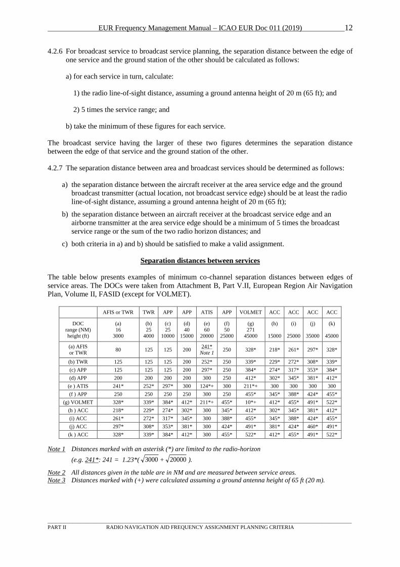
Separation distances between services
The table below presents examples of minimum co-channel separation distances between edges of
service areas. The DOCs were taken from Attachment B, Part V.II, European Region Air Navigation
Plan, Volume II, FASID (except for VOLMET).
AFIS or TWR TWR APP APP ATIS APP VOLMET ACC ACC ACC ACC
DOC
range (NM) height (ft)
(a)
16 3000
(b)
25 4000
(c)
25 10000
(d)
40 15000
(e)
60 20000
(f)
50 25000
(g)
271 45000
(h)
15000
(i)
25000
(j)
35000
(k)
45000
(a) AFIS
or TWR 80 125 125 200
U241*
Note 1 250 328* 218* 261* 297* 328*
(b) TWR 125 125 125 200 252* 250 339* 229* 272* 308* 339*
(c) APP 125 125 125 200 297* 250 384* 274* 317* 353* 384*
(d) APP 200 200 200 200 300 250 412* 302* 345* 381* 412*
(e ) ATIS 241* 252* 297* 300 124*+ 300 211*+ 300 300 300 300
(f ) APP 250 250 250 250 300 250 455* 345* 388* 424* 455*
(g) VOLMET 328* 339* 384* 412* 211*+ 455* 10*+ 412* 455* 491* 522*
(h ) ACC 218* 229* 274* 302* 300 345* 412* 302* 345* 381* 412*
(i) ACC 261* 272* 317* 345* 300 388* 455* 345* 388* 424* 455*
(j) ACC 297* 308* 353* 381* 300 424* 491* 381* 424* 460* 491*
(k ) ACC 328* 339* 384* 412* 300 455* 522* 412* 455* 491* 522*
Note 1 Distances marked with an asterisk (*) are limited to the radio-horizon
(e.g. U241*U: 241 = 1.23*( 3000 + 20000 ).
Note 2 All distances given in the table are in NM and are measured between service areas.
Note 3 Distances marked with (+) were calculated assuming a ground antenna height of 65 ft (20 m).
EUR Frequency Management Manual – ICAO EUR Doc 011 (2019) 13
_________________________________________________________________________________________________________________
PART II RADIO NAVIGATION AID FREQUENCY ASSIGNMENT PLANNING CRITERIA
Consideration of terrain in compatibility assessment
4.2.8 Frequency managers are encouraged to take into consideration the effect of terrain when
conducting frequency compatibility assessment. When assessing frequency compatibility
between co-channel assignments, in cases where the path profile of the undesired co-channel
transmission is intersected by terrain, the resulting undesired field strength at a receiver can be
expected to be lower by at least 6 dB than that which would be achieved if the signal path was
unobstructed. This equates to a 50% reduction in the undesired path length. The following
approach to assessing compatibility in these cases is recommended.
4.2.9 The 5:1 Case
4.2.9.1 In cases where the co-channel planning rule requires that the separation distance between the
edges of two services should be 5 times the larger of their respective DOCs (e.g. circular-
versus-circular), compatibility can generally be assumed when:
a) The undesired signal path is intercepted by terrain; and
b) The distance between the edges of the DOCs is not less than 2.5 times the path length of
the desired signal.
4.2.10 The RLOS case
4.2.10.1 In cases where the co-channel planning rules require that the minimum separation distance
between DOC edges is the sum of the RLOS distances of the two services (e.g. area-versus-
area), compatibility can generally be assumed when:
a) The undesired signal path is intercepted by terrain; and
b) The distance between the edges of the DOCs is not less than 5 times the path length of the
desired signal.
4.2.10.2 In the case of area services where the length of the desired path is not known (i.e. where the
ground station location has not been coordinated), it is recommended that the desired path
length is taken to be 70% of the length of the maximum diagonal of the desired DOC
polygon.
Notes:
1. MANIF AFM provides a capability for conducting the compatibility assessment using the
above criteria;
2. A technical justification for the above recommendations is provided in the Supplement to
ICAO EUR Doc 011.
4.2.11 Recording of terrain masking in SAFIRE
4.2.11.1 Where a State coordinates a new assignment that does not comply with the co-channel
planning rules but, by reason of the terrain effects described above, is deemed to be
compatible with another existing assignment or with a proposal under coordination, a
relevant remark should be provided in the SAFIRE Remarks field simply by inserting the
word "TERRAIN".
VDL TO VDL & OTHER SERVICES
4.2.12 The separation distance between VDL and DSB-AM as well as between VDL and another
VDL service shall be calculated using the radio horizon method. The separation distance
between the service edges of the two services shall be the sum of their radio horizon
EUR Frequency Management Manual – ICAO EUR Doc 011 (2019) 14
_________________________________________________________________________________________________________________
PART II RADIO NAVIGATION AID FREQUENCY ASSIGNMENT PLANNING CRITERIA
distances.
AERODROME SURFACE ASSIGNMENTS
4.2.13 Aerodrome Surface assignments should be planned according to the following guidance:
4.2.13.1. The band [121.5417 to 121.9916 MHz] inclusive is reserved exclusively for aerodrome
surface movement assignments (AS).
4.2.13.2. The DOC area should be coordinated as circular, with a radius of 5NM and a maximum
antenna height of 100ft (C-5/1).
4.2.13.3. AS assignments used for ATS purposes should be coordinated as protected.
4.2.13.4. AS assignments should be co-ordinated preferably in the dedicated band [121.5417 to
121.9916 MHz] inclusive. If it is necessary to plan an AS assignment outside of this band, it
should be coordinated on a temporary basis.
EUR Frequency Management Manual – ICAO EUR Doc 011 (2019) 15
_________________________________________________________________________________________________________________
PART II RADIO NAVIGATION AID FREQUENCY ASSIGNMENT PLANNING CRITERIA
5 Adjacent channel separation distances between services
DSM-AM to DSB-AM
The following planning criteria should be used for the deployment of DSB AM RTF services on
adjacent channels:
5.1. Services with equal channel spacing (either 8.33 or 25 kHz) and frequency separation of one (1)
channel or with different channel spacing and frequency separation of 25 kHz:
a) These services may have overlapping service areas provided that a separation distance of at
least 10 NM is maintained between a ground receiver of one service and a ground transmitter
of the other service, except when both services under consideration are on 8.33 kHz channels
and at least one utilises offset carrier systems.
b) In the case of two 8.33 kHz services where one or both utilises an offset carrier system, the
separation distance between services should be determined on the basis of co-channel
separation criteria.
Note: For international co-ordination purposes, the only requirement for States in this case is to notify to a
neighbouring State the location of ground receivers and ground transmitters that are located within
10NM of the land mass of the neighbouring State except when they are sited at the centre of a circular
service. Notwithstanding, States are urged to ensure compliance with the constraint in a) within their own
territories.
5.2. Services using different channel spacing and frequency separation of 8.33 kHz:
The distance separation of services as above should be determined on the basis of co-channel
separation criteria.
5.3. Services using different channel spacing and frequency separation of 16.67 kHz:
a) The separation distance between edges of service areas should be at least 10 NM except
when both services under consideration are broadcast services;
b) A broadcast service may have an overlapping service area with another broadcast service
provided that the ground transmitter of each service is at least 10 NM outside the edge of the
service area of the other service.
Note 1: These planning rules are based on the assumption that the ground transmitters and receivers are placed
within the protected service volume.
Note 2: As a consequence of the above criteria, adjacent channel services for ATS purposes should not be
deployed in the same airport.
Note 3: Where a State proposes a new offset-carrier service where the location of the ground transmitter(s) may
affect an existing foreign assignment, it is the responsibility of that State to ensure that sufficient
technical data is made available to the adjacent State(s) through bi-lateral coordination to allow the
other State to complete a compatibility assessment.”
VDL to VDL & Other Services
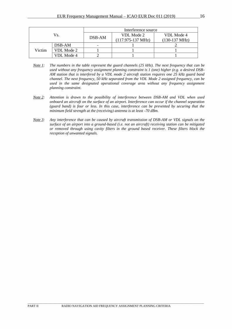
5.4. Adjacent channel separation between VDL and DSB-AM systems operating in the same
geographical area shall be in accordance with the following table.
EUR Frequency Management Manual – ICAO EUR Doc 011 (2019) 16
_________________________________________________________________________________________________________________
PART II RADIO NAVIGATION AID FREQUENCY ASSIGNMENT PLANNING CRITERIA
Vs.
Interference source
DSB-AM VDL Mode 2
(117.975-137 MHz)
VDL Mode 4
(130-137 MHz)
Victim
DSB-AM - 1 2
VDL Mode 2 1 1 1
VDL Mode 4 2 1 1
Note 1: The numbers in the table represent the guard channels (25 kHz). The next frequency that can be
used without any frequency assignment planning constraint is 1 (one) higher (e.g. a desired DSB-
AM station that is interfered by a VDL mode 2 aircraft station requires one 25 kHz guard band
channel. The next frequency, 50 kHz separated from the VDL Mode 2 assigned frequency, can be
used in the same designated operational coverage area without any frequency assignment
planning constraint.
Note 2: Attention is drawn to the possibility of interference between DSB-AM and VDL when used
onboard an aircraft on the surface of an airport. Interference can occur if the channel separation
(guard band) is four or less. In this case, interference can be prevented by securing that the
minimum field strength at the (receiving) antenna is at least -70 dBm.
Note 3: Any interference that can be caused by aircraft transmission of DSB-AM or VDL signals on the
surface of an airport into a ground-based (i.e. not an aircraft) receiving station can be mitigated
or removed through using cavity filters in the ground based receiver. These filters block the
reception of unwanted signals.
EUR Frequency Management Manual – ICAO EUR Doc 011 (2019) 17
_________________________________________________________________________________________________________________
PART II RADIO NAVIGATION AID FREQUENCY ASSIGNMENT PLANNING CRITERIA
6 Operational Control
6.1 Dedicated frequencies for operational control purposes should be assigned to those aircraft
operators who are required to maintain a system of Operational Control under the provisions of
Annex 6, Part I.
6.2 Strict economy in the number and use of frequencies assigned for this purpose should be
observed. Shared use of channels by different operators is a method which may help to achieve
this goal. Eurocontrol can provide advice to States (see paragraph 1.3.3).
6.3 The Annex 10 provisions for frequency protection should not apply to OPC frequencies used in
the EUR region.
7 Utilization of the Frequency Band 112 – 117.975 MHz
7.1 In accordance with provisions of the Regional Supplementary Procedures (Doc 7030), based on
an agreement reached at FMG/21, the assignment of VDL Mode 4 frequencies in the band 112 –
117.975 MHz shall not be permitted until further notice.
Note: Currently, all navigation aids operating in the band 112-117.975 MHz make use of ground
based transmitters and no transmissions take place from the aircraft. There is the potential for
aircraft-based VDL Mode 4 transmissions to cause harmful interference to the users of these
existing ground-based navigation aids, and their monitors, unless a capability is provided to
prohibit unintended VDL Mode 4 transmission outside of designated operational coverage. It is
not currently clear whether this capability is available and further studies need to be conducted.
7.2 Subject to a satisfactory solution ensuring that VDL Mode 4 transmission do not cause harmful
interference to other users of the band, the Regional Supplementary Procedures FMG may be
amended to remove the above restriction. In those circumstances, in accordance with the
provisions of Annex 10 and the ITU Radio Regulations, the frequency band 112 – 117.975 MHz
could be used for VDL Mode 4. When making frequency assignments to VDL Mode 4 in this
frequency band, the following frequency assignment planning parameters apply:
7.3 VDL Mode 4 to VDL and VHF DSB/AM (air/ground voice)
7.3.1 Co-frequency
Note: the frequency band 112 – 117.975 MHz is (currently) not to be used for VHF DSB/AM or VDL mode 3
systems as per provisions of Annex 10, Volume III and no co-frequency assignment planning to secure
compatibility between VDL Mode 4 and VHF DSB/AM or VDL Mode 2 are necessary.
Co-frequency use of frequencies for VDL Mode 4 (different VDL Mode 4 networks)
The separation distance between VDL Mode 4 frequency assignments shall be calculated using
the radio horizon method. The separation distance between the service edges of the two services
shall be equal or greater than the sum of their respective distances to the radio horizon (see also
paragraphs 4.2.8 above)
7.3.2 Adjacent frequency
Adjacent channel compatibility of VDL Mode 4 with DSB/AM or VDL Mode 2 systems is
secured when applying the provisions of paragraph 5.4 above.
EUR Frequency Management Manual – ICAO EUR Doc 011 (2019) 18
_________________________________________________________________________________________________________________
PART II RADIO NAVIGATION AID FREQUENCY ASSIGNMENT PLANNING CRITERIA
7.4 VDL Mode 4 and ILS-Localizer
7.4.1 Co-frequency
Note: Since, in accordance with the provisions of Annex 10 (Volumes I and II) the highest assignable frequency
for the ILS Localizer is 111.950 MHz and the lowest assignable VDL Mode 4 frequency is 112 MHz, no
co-frequency use of VDL Mode 4 and the ILS Localizer is expected.
7.4.2 Adjacent frequency
Note: Since, in accordance with the provisions of Annex 10 (Volumes I and III) the highest assignable frequency
for the ILS Localizer is 111.950 MHz and the lowest assignable frequency for VDL Mode 4 is 112 MHz,
the minimum frequency separation between an ILS-Localizer frequency and a VDL Mode 4 frequency is
50 kHz.
VDL Mode 4 can be used without frequency assignment planning constraints when separated
from an operational ILS-Localizer frequency with 50 kHz or more.
Note: In certain cases VDL Mode 4 may be subject to harmful interference from transmissions from the ILS-
Localizer transmitter if the separation distance is less than 2.5 NM. Such interference is typically
transient in nature.
7.5 VDL Mode 4 and VOR
7.5.1 Co-frequency and first adjacent (25 kHz) frequency
The separation distance between VDL Mode 4 and VOR frequency assignments shall be
calculated using the radio horizon method. The separation distance between the service edges
of the two services shall be equal or greater than the sum of their respective distance to the
radio horizon.
7.5.2 Second adjacent frequency (50 kHz separation between VOR and VDL Mode 4
frequency assignments)
VDL Mode 4 can be used without frequency assignment planning constraints when separated
from an operational VOR station with 50 kHz or more.
Note: In certain cases VDL Mode 4 may be subject to harmful interference from transmissions from the VOR
transmitter if the separation distance is less than 2.5 NM. Such interference is typically transient in
nature.
7.6 VDL Mode 4 and GBAS
7.6.1 Co-frequency and first adjacent (25 kHz) frequency
The co-frequency separation distance between VDL Mode 4 and GBAS frequency assignments
shall be calculated using the radio horizon method. The separation distance between the service
edges of the two services shall be equal or greater than the sum of their respective distance to
the radio horizon.
The first adjacent (25kHz) frequency channel separation distance shall be 10 Km between the
service edge of the GBAS VDB and any VDL4 transmitter.
7.6.2 Second adjacent frequency (50 kHz separation between VDL Mode 4 and GBAS)
EUR Frequency Management Manual – ICAO EUR Doc 011 (2019) 19
_________________________________________________________________________________________________________________
PART II RADIO NAVIGATION AID FREQUENCY ASSIGNMENT PLANNING CRITERIA
VDL Mode 4 can be used without frequency assignment planning constraints when separated
from an operational GBAS station with 50 kHz or more.
Note: VDL Mode 4 should not operate on the 2nd
, 3rd
or 4th adjacent channel to a VDB GBAS frequency at the
surface of an airport in case the separation between a VDB GBAS and a VDL Mode 4 equipped aircraft
can be less than 130 m. Note: This is an operating restriction that may affect the use of VDL Mode 4 on
an airport.
8 VDL Mode 2 Assignments
8.1 In order to support evolution of the VDL band plan, the VHF data link assignments should be
coordinated as follows:
a) Assignments on auxiliary frequencies should be made on temporary basis to support
changes to the Data Link Allotment Plan accordingly;
b) Assignments should be deleted if the frequencies are not used within one year;
c) Discrete assignments should be made for each CSP at each location;
d) Assignments should be coordinated as DL services with a DOC of C-1/0 and include the
precise location of the ground station(s) and their EIRP;
e) Assignments should include the CSP name and the ground station identifier in the Remarks
field.
9 VDL Mode 4 Assignments
9.1 In order to support evolution of the VDL band plan, VDL Mode 4 assignments on the VDL4
Common Signalling Channel (CSC) 136.925 should be coordinated as follows:
a) Assignments on channel 136.925 should be on a temporary basis to support changes to the
Data Link Allotment Plan accordingly;
b) Assignments should be deleted if the frequencies are not used within one year;
c) States using VDL4 should create Assignments on channel 136.925. Assignments should be
coordinated as DL services with the text “VDL4 CSC” in the SAFIRE Remarks field;
d) Protected polygonal assignments should be created in the areas where aircraft will use
VDL4 CSC;
e) Discrete assignments could be made for each fixed ground station: they should include the
precise location of the ground station(s) and their EIRP. In addition, they should contain the
operator name in the Remarks field.
EUR Frequency Management Manual – ICAO EUR Doc 011 (2019) 20
_________________________________________________________________________________________________________________
PART III RADIO NAVIGATION AID FREQUENCY ASSIGNMENT PLANNING CRITERIA
PART III RADIO NAVIGATION AID FREQUENCY ASSIGNMENT
PLANNING CRITERIA
1 NDB and locator
1.1 General
1.1.1 A number of sub-bands in the range of 255 – 526.5 kHz (excluding 495 - 505 kHz) are allocated
to aeronautical radio navigation with various status. Only the sub-band 325 - 405 kHz is
allocated exclusively to the aeronautical radio navigation service, the other sub-bands being
shared with other services.
1.1.1.1. As for the other users of the band, the sub-band 255 - 283.5 kHz is mainly used by
broadcasting stations, while the sub-bands 283.5 - 315 kHz and 315 - 325 kHz are used by
maritime beacons. The small segment 405 - 415 kHz is designated for radio direction-finding
in the maritime radio navigation service, while the sub-bands in the range 415 - 526.5 kHz
(excluding the segment 495 – 505 kHz) are used by the maritime mobile service, limited to
radiotelegraphy.
1.1.1.2. It is noted additionally that Rradio frequency carrier systems are widely used for remote
control or transmission of speech or data over segments of high-voltage overhead power lines.
In some cases frequencies in the LF/MF bands are used and this has been proved to be able to
affect ADF indications in aircraft at several nautical miles from the power lines.
1.1.2 Organization of Planning
1.1.2.1. In order to secure the international and the operational status of their assignments, States are
required to apply the rules and procedures of the ITU Radio Regulations. This is particularly
necessary for the shared sub-bands, since the ICAO EUR Table COM4 is not supposed to
include non-aeronautical assignments.
1.1.2.2. For assignments in the aeronautical radio navigation service, States are required to apply the
ICAO EUR FMG rules and procedures.
Note 1: Although in the shared sub-bands the FMG process is evidently partial and cannot result, if applied
alone, in the required status, this process is necessary for the co-ordination of the identifications of
the radio navigation aids.
Note 2: In the shared sub-bands, States are advised to avoid including assignments for non-aeronautical
services (e.g. maritime services) in the FMG co-ordination process, as such assignments are not
taken into account in compatibility assessments.
1.1.3 References to documents:
- Annex 10, Volume I, Attachment C, paragraph 6.2.1.6
(field strength);
- Annex 10, Volume V, paragraph 3.2
(general about protection, sharing and frequency congestion);
- Annex 10, Attachment A to Volume V
(protection, receiver characteristics, filter attenuation);
- European Region Air Navigation Plan (Doc 7754), Volume II, FASID, Part IV, paragraphs 19-20
(reference to Table COM4).
EUR Frequency Management Manual – ICAO EUR Doc 011 (2019) 21
_________________________________________________________________________________________________________________
PART III RADIO NAVIGATION AID FREQUENCY ASSIGNMENT PLANNING CRITERIA
1.1.4 The range can be from 10 NM (nautical miles) up to 100 NM (in some rare cases more) and the
operational range is listed in the national AIP and the frequency assignment table. The
maximum altitude is not specified. Co-channel separation between two transmitters shall be
such that an unwanted signal is more than 15 dB below the wanted signal within the specified
service area (DOC). This protection criterion is also included in the ITU Radio Regulations. The
bandwidth characteristics of the airborne receiver need to be taken into account which require in
principle that existing transmitters within ± 7 kHz from the frequency of the wanted station be
considered.
1.1.5 In the band 325 - 405 kHz, aviation is the only user and new assignments should therefore
preferably be made in this segment. Use of a segment where aeronautical radio navigation is
secondary should only be considered in areas where the primary service is not used, like inland
areas where the distance to any maritime station is sufficient.
1.1.6 The co-ordination of LF/MF radio navigation aids to be applied for aeronautical purposes above
526.5 kHz shall be carried out between national radio regulators, applying the relevant ITU
procedures. The co-ordination of the identification of such a radio navigation aid shall be carried
out between FMG members according to the rules in Part IV.
1.1.7 For normal coverage ranges (15 - 50 NM) co-ordination should, as an absolute minimum, be
made with States within a radius of 300 - 400 NM. Co-ordination should also be made with the
national authority responsible for protection of the maritime services if a shared band segment is
to be used.
1.1.8 Information on the planning of identifications can be found in section 7.
1.2 Frequency Assignment Planning Principles
1.2.1 Wherever possible, frequencies at kHz points (i.e. integral multiples of 1 kHz) in the bands used
for NDBs should be chosen to meet particular requirements. Frequency assignments at 0.5 kHz
points may also be utilized, provided the full required protection can be ensured.
1.2.2 In the planning of frequency assignments, ADF receiver characteristics as specified in paragraph
3 of Attachment A to Annex 10, Volume V, should be assumed.
1.2.3 For the purpose of assessing the signal attenuation with distance, the LF/MF ground wave
propagation curves agreed by the ITU-R should be used, taking into account the frequency of
operation and the effect of mixed land/sea path where appropriate.
1.3 Frequency Assignment Planning Criteria
1.3.1 The protection of a NDB against interference from another NDB can be calculated using the
propagation curves in Recommendation ITU-R P.368-9. These curves (known also as CCIR
curves) represent the propagation characteristics of a transmitter (beacon) with an effective
monopole radiated power (e.m.r.p.) of 1 kW. These curves can be adjusted to describe the
propagation characteristics (field strength as a function of the distance from the beacon) of a
beacon with a given coverage area. Such adjustment needs to ensure that the field strength at the
edge of the coverage area is the minimum required. For aeronautical beacons this field strength
is 70 µV/m or 36.9 dB (µV/m). (Ref.: Annex 10, Volume I, section 3.4 and ITU Radio
Regulations Appendix 12).
1.3.2 For frequency planning purposes, the CCIR curves for sea water and wet ground propagation are
used, with the following characteristics:
EUR Frequency Management Manual – ICAO EUR Doc 011 (2019) 22
_________________________________________________________________________________________________________________
PART III RADIO NAVIGATION AID FREQUENCY ASSIGNMENT PLANNING CRITERIA
Sea water: σ = 5 S/m Wet ground: σ = 10P-2P S/m
ε = 70 ε = 30
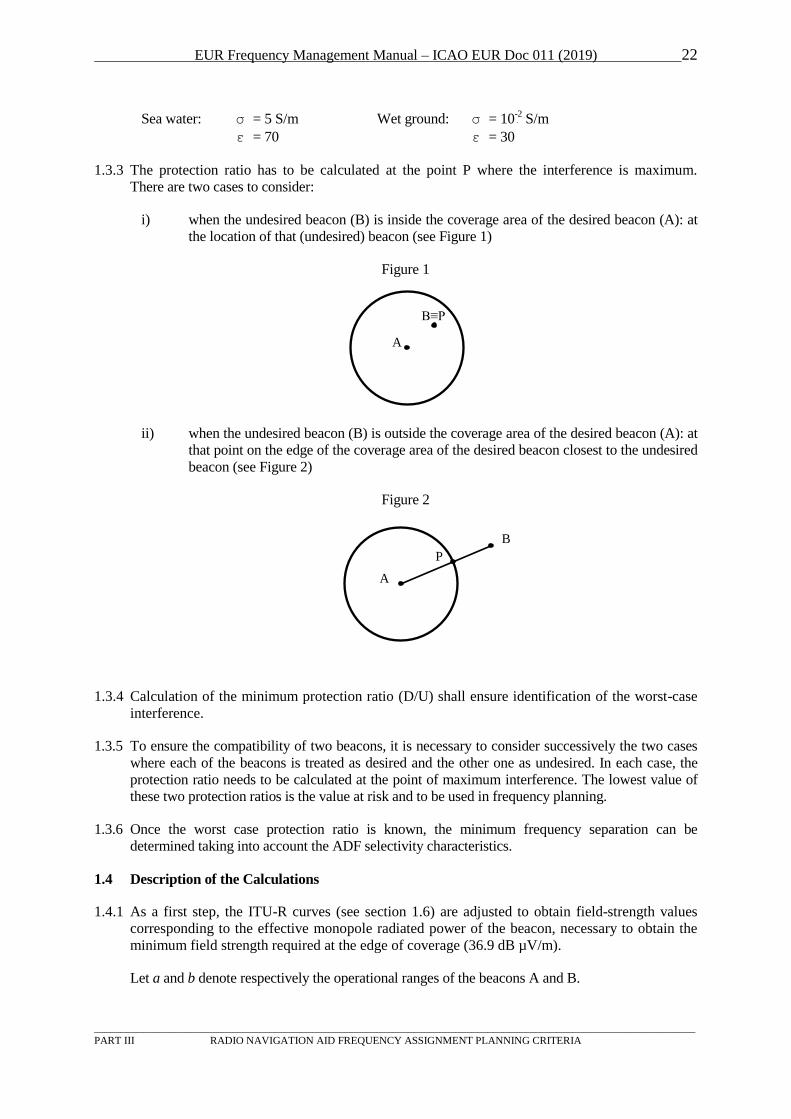
1.3.3 The protection ratio has to be calculated at the point P where the interference is maximum.
There are two cases to consider:
i) when the undesired beacon (B) is inside the coverage area of the desired beacon (A): at
the location of that (undesired) beacon (see Figure 1)
Figure 1
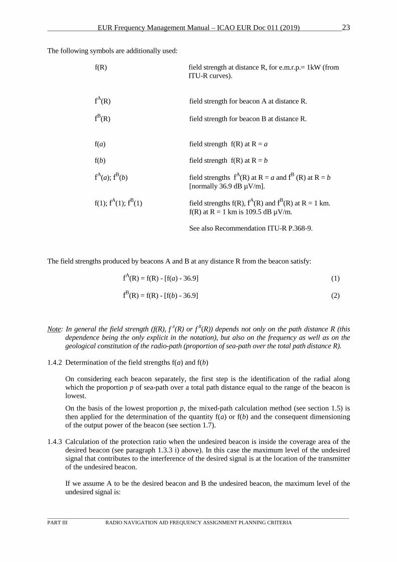
ii) when the undesired beacon (B) is outside the coverage area of the desired beacon (A): at
that point on the edge of the coverage area of the desired beacon closest to the undesired
beacon (see Figure 2)
Figure 2
1.3.4 Calculation of the minimum protection ratio (D/U) shall ensure identification of the worst-case
interference.
1.3.5 To ensure the compatibility of two beacons, it is necessary to consider successively the two cases
where each of the beacons is treated as desired and the other one as undesired. In each case, the
protection ratio needs to be calculated at the point of maximum interference. The lowest value of
these two protection ratios is the value at risk and to be used in frequency planning.
1.3.6 Once the worst case protection ratio is known, the minimum frequency separation can be
determined taking into account the ADF selectivity characteristics.
1.4 Description of the Calculations
1.4.1 As a first step, the ITU-R curves (see section 1.6) are adjusted to obtain field-strength values
corresponding to the effective monopole radiated power of the beacon, necessary to obtain the
minimum field strength required at the edge of coverage (36.9 dB µV/m).
Let a and b denote respectively the operational ranges of the beacons A and B.
A
B≡P
B
P
A
EUR Frequency Management Manual – ICAO EUR Doc 011 (2019) 23
_________________________________________________________________________________________________________________
PART III RADIO NAVIGATION AID FREQUENCY ASSIGNMENT PLANNING CRITERIA
The following symbols are additionally used:
f(R) field strength at distance R, for e.m.r.p.= 1kW (from
ITU-R curves).
fP
AP(R) field strength for beacon A at distance R.
fP
BP(R) field strength for beacon B at distance R.
f(a) field strength f(R) at R = a
f(b) field strength f(R) at R = b
fP
AP(a); fP
BP(b) field strengths fP
AP(R) at R = a and fP
BP (R) at R = b
[normally 36.9 dB µV/m].
f(1); fP
AP(1); fP
BPP(1) field strengths f(R), fP
AP(R) and fP
BP(R) at R = 1 km.
f(R) at R = 1 km is 109.5 dB µV/m.
See also Recommendation ITU-R P.368-9.
The field strengths produced by beacons A and B at any distance R from the beacon satisfy:
fP
AP(R) = f(R) - [f(a) - 36.9] (1)
fP
BP(R) = f(R) - [f(b) - 36.9] (2)
Note: In general the field strength (f(R), f A(R) or f
B(R)) depends not only on the path distance R (this
dependence being the only explicit in the notation), but also on the frequency as well as on the
geological constitution of the radio-path (proportion of sea-path over the total path distance R).
1.4.2 Determination of the field strengths f(a) and f(b)
On considering each beacon separately, the first step is the identification of the radial along
which the proportion p of sea-path over a total path distance equal to the range of the beacon is
lowest.
On the basis of the lowest proportion p, the mixed-path calculation method (see section 1.5) is
then applied for the determination of the quantity f(a) or f(b) and the consequent dimensioning
of the output power of the beacon (see section 1.7).
1.4.3 Calculation of the protection ratio when the undesired beacon is inside the coverage area of the
desired beacon (see paragraph 1.3.3 i) above). In this case the maximum level of the undesired
signal that contributes to the interference of the desired signal is at the location of the transmitter
of the undesired beacon.
If we assume A to be the desired beacon and B the undesired beacon, the maximum level of the
undesired signal is:
EUR Frequency Management Manual – ICAO EUR Doc 011 (2019) 24
_________________________________________________________________________________________________________________
PART III RADIO NAVIGATION AID FREQUENCY ASSIGNMENT PLANNING CRITERIA
EU B = fP
BP(1) = f(1) - [f(b) - 36.9]
= 109.5 - [f(b) - 36.9] (3)
The signal level of the desired facility A at this point of maximum interference is:
ED B = fP
AP(Rs) = f(Rs) - [f(a) - 36.9] 0<Rs<a (4)
Rs = separation distance between A and B.
The protection ratio D/U is: EBDB - EBUB or fP
AP(Rs) - fP
BP(1).
Substitution of (3) and (4) in this formula gives:
D/U = f(Rs) - f(a) + f(b) - 109.5 (5)
Note: For the application of formula (5), the quantity f(Rs) at the position of the undesired beacon is
determined by the application of the mixed-path calculation method (see section 1.5).
1.4.4 Calculation of the protection ratio when the undesired beacon is outside the coverage area of the
desired beacon (see paragraph 1.3.3 ii) above). In this case the maximum level of the undesired
signal that contributes to the interference of the desired signal is at the location of point P in
Figure 2.
At this point the signal level of the desired facility A is:
ED B = fP
AP(a*) = f(a*) - [f(a) - 36.9]
(6)
(fA(a*), f(a*) denote respectively the adjusted and the non-adjusted (corresponding to
e.m.r.p.=1kW) field strengths at the particular point P).
The signal level of the undesired facility B at this point is:
EU = fP
BP(Rs - a)
= f(Rs - a) - [f(b) - 36.9] , a<Rs, (7)
Rs = separation distance between beacon A and B.
The protection ratio D/U is: EBDB - EBUB or fP
AP(a*) - fP
BP(Rs-a).
Substitution of (6) and (7) in this formula gives:
D/U = f(b) - f(Rs - a) + f(a*) - f(a). (8)
Note: For the application of formula (8), the quantities f(a*) and f(Rs-a) are determined by the
application of the mixed-path calculation method (see section 1.5), f(a*) corresponding to the
propagation path AP, while f(Rs-a) corresponding to propagation path BP (see Figure 2).
1.4.5 Formulas (5) and (8) can be used to calculate the interference from beacon B (undesired) to
beacon A (desired). When the outcome of the calculations shows that the D/U is equal or greater
than 15 dB, the desired beacon is protected and the beacons can operate on the same frequency.
When the outcome is less than 15 dB, a frequency separation between the frequencies assigned
to these beacons has to be maintained.
The required frequency-separation depends upon the calculated D/U ratio and can be taken from
the following table:
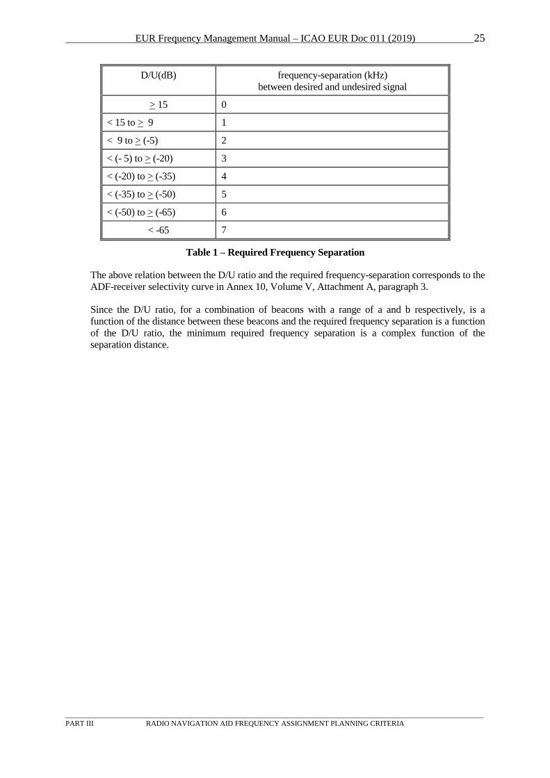
EUR Frequency Management Manual – ICAO EUR Doc 011 (2019) 25
_________________________________________________________________________________________________________________
PART III RADIO NAVIGATION AID FREQUENCY ASSIGNMENT PLANNING CRITERIA
D/U(dB) frequency-separation (kHz)
between desired and undesired signal
U>U 15 0
< 15 to U>U 9 1
< 9 to U>U (-5) 2
< (- 5) to U>U (-20) 3
< (-20) to U>U (-35) 4
< (-35) to U>U (-50) 5
< (-50) to U>U (-65) 6
< -65 7
Table 1 – Required Frequency Separation
The above relation between the D/U ratio and the required frequency-separation corresponds to the
ADF-receiver selectivity curve in Annex 10, Volume V, Attachment A, paragraph 3.
Since the D/U ratio, for a combination of beacons with a range of a and b respectively, is a
function of the distance between these beacons and the required frequency separation is a function
of the D/U ratio, the minimum required frequency separation is a complex function of the
separation distance.
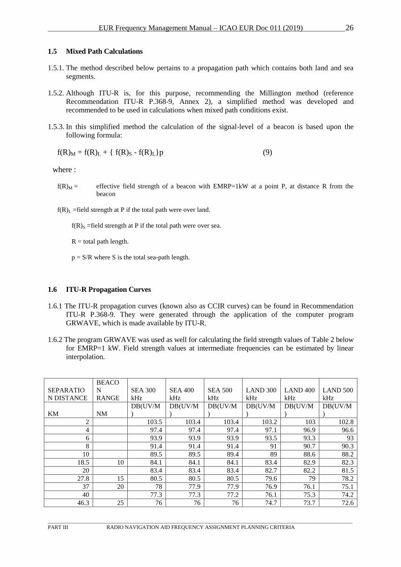
EUR Frequency Management Manual – ICAO EUR Doc 011 (2019) 26
_________________________________________________________________________________________________________________
PART III RADIO NAVIGATION AID FREQUENCY ASSIGNMENT PLANNING CRITERIA
1.5 Mixed Path Calculations
1.5.1. The method described below pertains to a propagation path which contains both land and sea
segments.
1.5.2. Although ITU-R is, for this purpose, recommending the Millington method (reference
Recommendation ITU-R P.368-9, Annex 2), a simplified method was developed and
recommended to be used in calculations when mixed path conditions exist.
1.5.3. In this simplified method the calculation of the signal-level of a beacon is based upon the
following formula:
f(R)M = f(R)L + { f(R)S - f(R)L}p (9)
where :
f(R)M = effective field strength of a beacon with EMRP=1kW at a point P, at distance R from the
beacon
f(R)L =field strength at P if the total path were over land.
f(R)S =field strength at P if the total path were over sea.
R = total path length.
p = S/R where S is the total sea-path length.
1.6 ITU-R Propagation Curves
1.6.1 The ITU-R propagation curves (known also as CCIR curves) can be found in Recommendation
ITU-R P.368-9. They were generated through the application of the computer program
GRWAVE, which is made available by ITU-R.
1.6.2 The program GRWAVE was used as well for calculating the field strength values of Table 2 below
for EMRP=1 kW. Field strength values at intermediate frequencies can be estimated by linear
interpolation.
SEPARATIO
N DISTANCE
BEACO
N
RANGE
SEA 300
kHz
SEA 400
kHz
SEA 500
kHz
LAND 300
kHz
LAND 400
kHz
LAND 500
kHz
KM NM
DB(UV/M
)
DB(UV/M
)
DB(UV/M
)
DB(UV/M
)
DB(UV/M
)
DB(UV/M
)
2 103.5 103.4 103.4 103.2 103 102.8
4 97.4 97.4 97.4 97.1 96.9 96.6
6 93.9 93.9 93.9 93.5 93.3 93
8 91.4 91.4 91.4 91 90.7 90.3
10 89.5 89.5 89.4 89 88.6 88.2
18.5 10 84.1 84.1 84.1 83.4 82.9 82.3
20 83.4 83.4 83.4 82.7 82.2 81.5
27.8 15 80.5 80.5 80.5 79.6 79 78.2
37 20 78 77.9 77.9 76.9 76.1 75.1
40 77.3 77.3 77.2 76.1 75.3 74.2
46.3 25 76 76 76 74.7 73.7 72.6
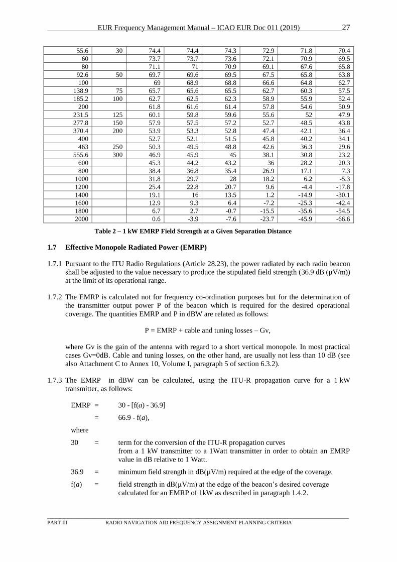
EUR Frequency Management Manual – ICAO EUR Doc 011 (2019) 27
_________________________________________________________________________________________________________________
PART III RADIO NAVIGATION AID FREQUENCY ASSIGNMENT PLANNING CRITERIA
55.6 30 74.4 74.4 74.3 72.9 71.8 70.4
60 73.7 73.7 73.6 72.1 70.9 69.5
80 71.1 71 70.9 69.1 67.6 65.8
92.6 50 69.7 69.6 69.5 67.5 65.8 63.8
100 69 68.9 68.8 66.6 64.8 62.7
138.9 75 65.7 65.6 65.5 62.7 60.3 57.5
185.2 100 62.7 62.5 62.3 58.9 55.9 52.4
200 61.8 61.6 61.4 57.8 54.6 50.9
231.5 125 60.1 59.8 59.6 55.6 52 47.9
277.8 150 57.9 57.5 57.2 52.7 48.5 43.8
370.4 200 53.9 53.3 52.8 47.4 42.1 36.4
400 52.7 52.1 51.5 45.8 40.2 34.1
463 250 50.3 49.5 48.8 42.6 36.3 29.6
555.6 300 46.9 45.9 45 38.1 30.8 23.2
600 45.3 44.2 43.2 36 28.2 20.3
800 38.4 36.8 35.4 26.9 17.1 7.3
1000 31.8 29.7 28 18.2 6.2 -5.3
1200 25.4 22.8 20.7 9.6 -4.4 -17.8
1400 19.1 16 13.5 1.2 -14.9 -30.1
1600 12.9 9.3 6.4 -7.2 -25.3 -42.4
1800 6.7 2.7 -0.7 -15.5 -35.6 -54.5
2000 0.6 -3.9 -7.6 -23.7 -45.9 -66.6
Table 2 – 1 kW EMRP Field Strength at a Given Separation Distance
1.7 Effective Monopole Radiated Power (EMRP)
1.7.1 Pursuant to the ITU Radio Regulations (Article 28.23), the power radiated by each radio beacon
shall be adjusted to the value necessary to produce the stipulated field strength (36.9 dB (µV/m))
at the limit of its operational range.
1.7.2 The EMRP is calculated not for frequency co-ordination purposes but for the determination of
the transmitter output power P of the beacon which is required for the desired operational
coverage. The quantities EMRP and P in dBW are related as follows:
P = EMRP + cable and tuning losses – Gv,
where Gv is the gain of the antenna with regard to a short vertical monopole. In most practical
cases Gv=0dB. Cable and tuning losses, on the other hand, are usually not less than 10 dB (see
also Attachment C to Annex 10, Volume I, paragraph 5 of section 6.3.2).
1.7.3 The EMRP in dBW can be calculated, using the ITU-R propagation curve for a 1 kW
transmitter, as follows:
EMRP = 30 - [f(a) - 36.9]
= 66.9 - f(a),
where
30 = term for the conversion of the ITU-R propagation curves
from a 1 kW transmitter to a 1Watt transmitter in order to obtain an EMRP
value in dB relative to 1 Watt.
36.9 = minimum field strength in dB(µV/m) required at the edge of the coverage.
f(a) = field strength in dB(µV/m) at the edge of the beacon’s desired coverage
calculated for an EMRP of 1kW as described in paragraph 1.4.2.
EUR Frequency Management Manual – ICAO EUR Doc 011 (2019) 28
_________________________________________________________________________________________________________________
PART III RADIO NAVIGATION AID FREQUENCY ASSIGNMENT PLANNING CRITERIA
1.8 Treatment of Assignments over Polygonal Areas
1.8.1. In exceptional cases, frequency assignments can be co-ordinated over polygonal areas. In such a
case :
1.8.1.1. Frequency protection is accorded over the co-ordinated polygonal area.
1.8.1.2. The envisaged distance (range) between receiver and transmitting beacon is specified at co-
ordination in addition to the polygonal area. This range shall not exceed the length of the
maximum diagonal of the polygonal area.
1.8.1.3. The transmitting beacon can be anywhere inside the polygonal area.
1.8.2. The following instructions are provided for the calculation of the required D/U ratio involving
assignments over polygonal areas (referred to henceforth as area assignments) :
1.8.3. The field strength f(a) at the range of an area assignment is calculated by considering all
possible paths of length a within the polygonal area and by identifying the lowest sea-path
proportion among those paths.
1.8.4. Area assignment versus circular assignment.
1.8.4.1. Protection of the area assignment
1.8.4.1.1. If the centre of the circular assignment is inside the polygon of the area assignment,
formula (5) is applicable with Rs being equal to the minimum of (i) the range a of the area
assignment and (ii) the maximum distance between the centre of the circular assignment and
the polygon. f(Rs) can be calculated by considering the radial with the lowest sea-path
proportion among those radials of length Rs from the centre of the circular assignment which
end up within the polygon.
Note: When Rs=a, f(Rs)≥f(a). In general Rs=a does not imply f(Rs)=f(a) because the minimisation of
the sea-path proportion is effected over different sets of possible paths of length a.
1.8.4.1.2. If the centre of the circular assignment is outside the polygon of the area assignment,
formula (8) is applicable with Rs-a being equal to the distance between the centre of the
circular assignment and its closest point on the polygon. f(a*) can be calculated by
considering the radial with the lowest sea-path proportion among those radials which
originate from the point on the polygon closest to the centre of the circular assignment, have
length equal to the range a of the area assignment and end up within the polygon. If the
distance of this point from any other point on the polygon is less than the range a, the length
of the radial for the calculation of f(a*) is reduced to the maximum value of this distance.
1.8.4.2. Protection of the circular assignment
1.8.4.2.1 If the polygon of the area assignment overlaps with the coverage area of the circular
assignment, formula (5) is applicable with Rs being equal to the minimum of (i) the range a
of the circular assignment and (ii) the maximum distance between the centre of the circular
assignment and the polygon. f(Rs) can be calculated by considering the radial with the
lowest sea-path proportion among those radials of length Rs from the centre of the circular
assignment which end up within the polygon.
1.84.2.2 If the polygon of the area assignment does not overlap with the coverage area of the
circular assignment, formula (8) is applicable with Rs being equal to distance between the
EUR Frequency Management Manual – ICAO EUR Doc 011 (2019) 29
_________________________________________________________________________________________________________________
PART III RADIO NAVIGATION AID FREQUENCY ASSIGNMENT PLANNING CRITERIA
centre of the circular assignment and its closest point on the polygon. In this case the
situation is very similar to the compatibility between two circular assignments.
1.8.5. Area assignment versus area assignment
1.8.5.1 Protection of each area assignment
1.8.5.1.1 If the two polygonal areas overlap, formula (5) is applicable with Rs being equal to the
minimum of (i) the range a of the area assignment to be protected and (ii) the maximum
distance between any point in the intersection of the two polygonal areas and any other point
on the polygon to be protected. f(Rs) can be calculated by considering the path with the
lowest sea-path proportion among all possible paths of length Rs which originate from points
in the intersection of the two polygonal areas and end up within the polygon to be protected.
1.8.5.1.2 If the two polygonal areas do not overlap, formula (8) is applicable with Rs-a being equal
to distance between the two polygons. f(a*) can be calculated by considering the radial with
the lowest sea-path proportion among those radials which originate from the point on the
polygon to be protected closest to the opposite polygon, have length equal to the range a of
the area assignment to be protected and end up within the polygon to be protected. If the
distance of this point from any other point on the polygon to be protected is less than the
range a, the length of the radial for the calculation of f(a*) is reduced to the maximum value
of this distance.
EUR Frequency Management Manual – ICAO EUR Doc 011 (2019) 30
_________________________________________________________________________________________________________________
PART III RADIO NAVIGATION AID FREQUENCY ASSIGNMENT PLANNING CRITERIA
2 ILS
2.1 General
2.1.1 The band 108 - 112 MHz is used by ILS Localizer and VOR, on different channels and the ILS
Glide Path is using the band 328.6 - 335.4 MHz. Within the band 108 - 112 MHz, channels on
odd multiples of 100 kHz (108.10, 108.30, ...) are used for ILS. Normally channels spaced
100 kHz are used, however, in congested areas also the intermediate channels (50 kHz) may be
used.
2.1.2 References to documents:
- Annex 10, Attachment C to Volume I, paragraph 2.6
(signal ratios, localizer and glide path receiver protection requirements and distance
separations);
- Annex 10, Volume I, paragraphs 3.1.3.3 and 3.1.5.3
(localiser and glide path coverage);
- Annex 10, Volume I, paragraph 3.1.6
(localiser and glide path frequency pairing);
- European Region Air Navigation Plan (Doc 7754), Volume I, Basic ANP, Part IV,
paragraph 44
(geographical separation criteria and channel spacing).
2.1.3 The operational service area of an ILS localizer is defined Annex 10 and often formed as a "key-
hole" out to 25 NM. The ILS Glide Path has shorter range and the frequency is fixed in relation
to the ILS Localizer. The adjacent channel criteria require special attention, because the
localizer to glide path frequency pairing does not make sure that facilities on the adjacent
localizer channel are automatically using an adjacent glide path channel and vice versa (e.g.
330.65/110.95 MHz; 330.80/110.90 MHz; 330.95/111.95 MHz). Therefore, the frequency
assignment planning for localizer and glide path has to be performed separately.
2.1.4 For the co-channel case, the wanted signal must be at least 20 dB stronger than an unwanted
signal. The distance from the edge of the service area of the wanted station to another ILS on the
same frequency should be more than 80 NM. Another ILS on the first adjacent channel (50 kHz)
should not be closer than 5 NM.
2.1.5 The co-ordination should also take into account the risk of interference from broadcasting
stations in the band 87.5 - 108 MHz, due to interference caused by unwanted emissions into the
aeronautical band or generated in the airborne receiver. Rules for this are available from the
Recommendation ITU-R SM.1009-1 “Compatibility between the sound-broadcasting service in
the band of about 87 - 108 MHz and the aeronautical services in the band 108 - 118 MHz”.
2.1.6 Co-ordination should be made with States within a radius of at least 150 NM. Co-ordination
should also be made with the authority responsible for the analysis of the broadcasting versus
aeronautical situation.
2.1.7 Information on the planning of identifications can be found in section 7 below.
2.2 Frequency Assignment Planning Criteria
2.2.1 Frequencies for ILS facilities should be selected from the list at Annex 10, Volume I, 3.1.6.1 in
accordance with the regional agreement permitted under Annex 10, Volume V, 4.2.2.1. Where
DME is provided, the appropriate DME channel selected from Table A at Annex 10, Volume I,
Chapter 3 should be used.
EUR Frequency Management Manual – ICAO EUR Doc 011 (2019) 31
_________________________________________________________________________________________________________________
PART III RADIO NAVIGATION AID FREQUENCY ASSIGNMENT PLANNING CRITERIA
2.2.2 The co-channel and adjacent channel geographical separations between ILS localizers and
between ILS glide path installations should be as specified in Annex 10, Volume I,
Attachment C, 2.6 – for ILS localizers designed for 50 kHz channel spacing and for ILS glide
paths designed for 150 kHz channel spacing.
2.2.3 The geographical separations between ILS and VOR installations where they operate on an
adjacent frequency should conform to the criteria stated at Annex 10, Volume I,
Attachment C, 3.5.
2.3 Required Separation Distances
2.3.1 Table of required ILS localizer and glide path separation distances
Equipment
Frequency
Separation
Minimum separation between second facility
and the service volume of the
first facility (NM)
Localizer Co-Channel 80
50 kHz 5
Glide Path Co-Channel 50
150 kHz 1
Note 1. The above figures are based on the assumption of protection points for the localizer at 46 km
(25 NM) distance and 1900 m (6250 ft) height and for the ILS glide path at 10 NM distance
and 760 m (2500 ft) height.
Note 2. States, in applying the separations shown in the table, should recognize the necessity to site
the ILS and VOR facilities in a manner which will preclude the possibility of airborne
receiver error due to overloading by high unwanted signal levels when the aircraft is in the
initial and final approach phases.
Note 3. States, in applying the separations shown in the table, should recognize the necessity to site
ILS glide path facilities in a manner which will preclude the possibility of erroneous glide
path indications due to reception of adjacent channel signals when the desired signal ceases
to radiate for any reason while the aircraft is in the final approach phase.
Note 4. Criteria for geographical separation between ILS and VOR facilities operating in the band
108 - 112 MHz can be found in paragraph 3.5 of Attachment C to Volume I of Annex 10.
Note 5. Studies have shown that for an extended glide path range of 10 to 15 NM, a separation
distance of 2 NM instead of 1 NM for the adjacent channel provides adequate protection.
The co-channel is automatically protected by the localizer separation distance.
2.3.2 The horizontal extensions of the ILS localizer and glide path DOCs are shown in the figures
below.
Horizontal extension of the ILS localizer DOC
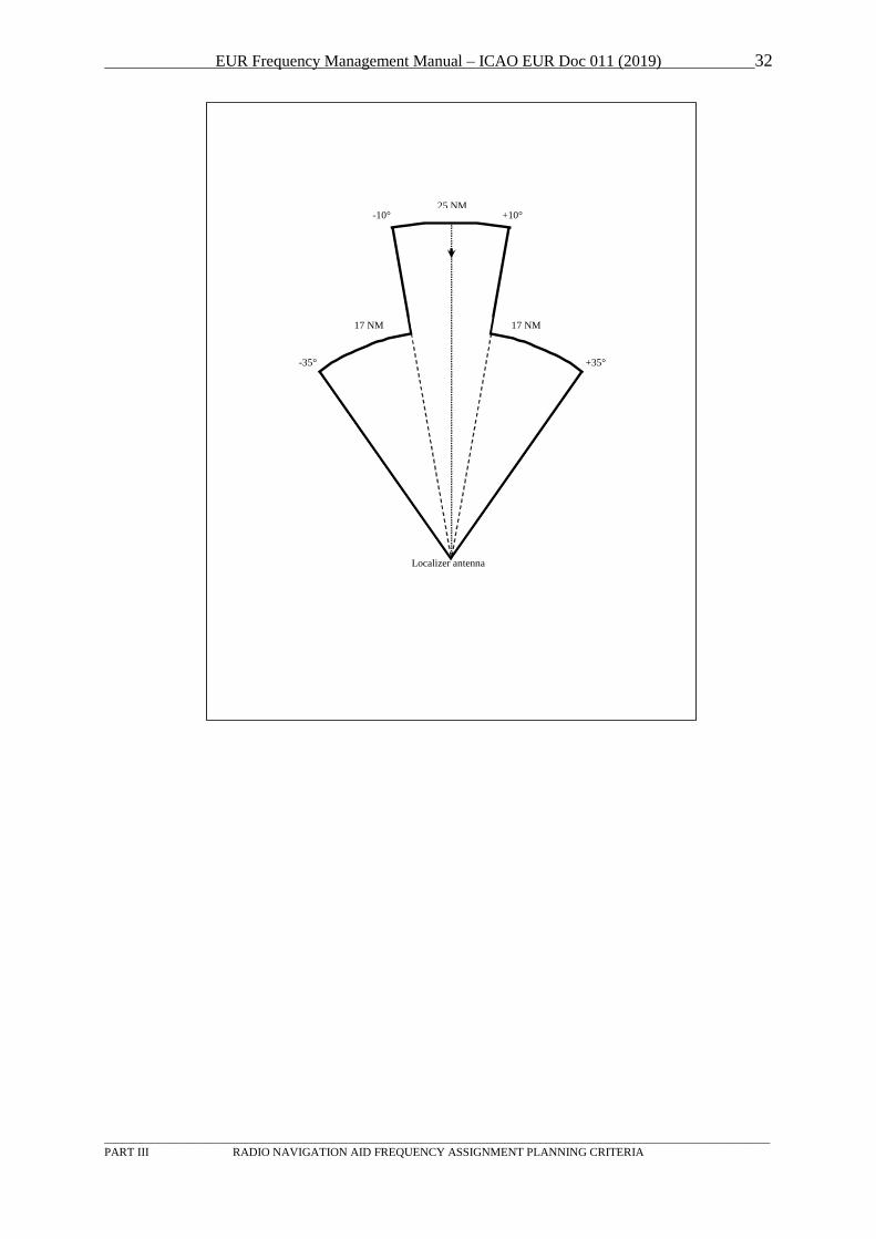
EUR Frequency Management Manual – ICAO EUR Doc 011 (2019) 32
_________________________________________________________________________________________________________________
PART III RADIO NAVIGATION AID FREQUENCY ASSIGNMENT PLANNING CRITERIA
-10° +10°
-35° +35°
25 NM
17 NM 17 NM
Localizer antenna

EUR Frequency Management Manual – ICAO EUR Doc 011 (2019) 33
_________________________________________________________________________________________________________________
PART III RADIO NAVIGATION AID FREQUENCY ASSIGNMENT PLANNING CRITERIA
Horizontal extension of the ILS glide path DOC
2.3.3 The glide path co-channel minimum separation distance of 50 NM does not require any specific
action, because it is indirectly and automatically provided for by the application of the localizer
co-channel minimum separation distance of 80 NM.
2.3.4 The adjacent channel glide path minimum separation distance of 1 NM does not require any
specific action for about half of the adjacent channels, because it is indirectly and automatically
covered by the adjacent localizer channel minimum separation distance of 5 NM.
Glide path antenna
+8° -8°
10 NM
EUR Frequency Management Manual – ICAO EUR Doc 011 (2019) 34
_________________________________________________________________________________________________________________
PART III RADIO NAVIGATION AID FREQUENCY ASSIGNMENT PLANNING CRITERIA
Column A of the table below lists the ILS channels. Column B lists the adjacent glide path channels
that require no specific action. Column C lists the adjacent glide path channels that do require specific
action (i.e. to check if the minimum required separation distance of 1 NM is respected).
A B C
LLZ / GP
(MHz)
adjacent GP / (LLZ)
(MHz)
adjacent GP / (LLZ)
(MHz)
108.10 / 334.70 334.55 / (108.15) 334.85 / (110.35)
108.15 / 334.55 334.70 / (108.10) 334.40 / (110.10)
108.30 / 334.10 333.95 / (108.35) 334.25 / (110.15)
108.35 / 333.95 334.10 / (108.30) 333.80 / (109.90)
108.50 / 329.90 329.75 / (108.55) 330.05 / (110.75)
108.55 / 329.75 329.90 / (108.50) 329.60 / (110.50)
108.70 / 330.50 330.35 / (108.75) 330.65 / (110.95)
108.75 / 330.35 330.50 / (108.70) 330.20 / (110.70)
108.90 / 329.30 329.15 / (108.95) 329.45 / (110.55)
108.95 / 329.15 329.30 / (108.90) - / (-)
109.10 / 331.40 331.25 / (109.15) 331.55 / (111.15)
109.15 / 331.25 331.40 / (109.10) 331.10 / (111.90)
109.30 / 332.00 331.85 / (109.35) 332.15 / (111.35)
109.35 / 331.85 332.00 / (109.30) 331.70 / (111.10)
109.50 / 332.60 332.45 / (109.55) 332.75 / (111.55)
109.55 / 332.45 332.60 / (109.50) 332.30 / (111.30)
109.70 / 333.20 333.05 / (109.75) 333.35 / (111.75)
109.75 / 333.05 333.20 / (109.70) 332.90 / (111.50)
109.90 / 333.80 333.65 / (109.95) 333.95 / (108.35)
109.95 / 333.65 333.80 / (109.90) 333.50 / (111.70)
110.10 / 334.40 334.25 / (110.15) 334.55 / (108.15)
110.15 / 334.25 334.40 / (110.10) 334.10 / (108.30)
110.30 / 335.00 334.85 / (110.35) - / (-)
110.35 / 334.85 335.00 / (110.30) 334.70 / (108.10)
110.50 / 329.60 329.45 / (110.55) 329.75 / (108.55)
110.55 / 329.45 329.60 / (110.50) 329.30 / (108.90)
110.70 / 330.20 330.05 / (110.75) 330.35 / (108.75)
110.75 / 330.05 330.20 / (110.70) 329.90 / (108.50)
110.90 / 330.80 330.65 / (110.95) 330.95 / (111.95)
110.95 / 330.65 330.80 / (110.90) 330.50 / (108.70)
111.10 / 331.70 331.55 / (111.15) 331.85 / (109.35)
111.15 / 331.55 331.70 / (111.10) 331.40 / (109.10)
111.30 / 332.30 332.15 / (111.35) 332.45 / (109.55)
111.35 / 332.15 332.30 / (111.30) 332.00 / (109.30)
111.50 / 332.90 332.75 / (111.55) 333.05 / (109.75)
111.55 / 332.75 332.90 / (111.50) 332.60 / (109.50)
111.70 / 333.50 333.35 / (111.75) 333.65 / (109.95)
111.75 / 333.35 333.50 / (111.70) 333.20 / (109.70)
111.90 / 331.10 330.95 / (111.95) 331.25 / (109.15)
111.95 / 330.95 331.10 / (111.90) 330.80 / (110.90)
2.3.5 The ILS co-ordinates provided shall be those of the localizer antenna system.
2.3.6 The calculation of the required separations distances may be simplified by the following
procedures (see figures below):
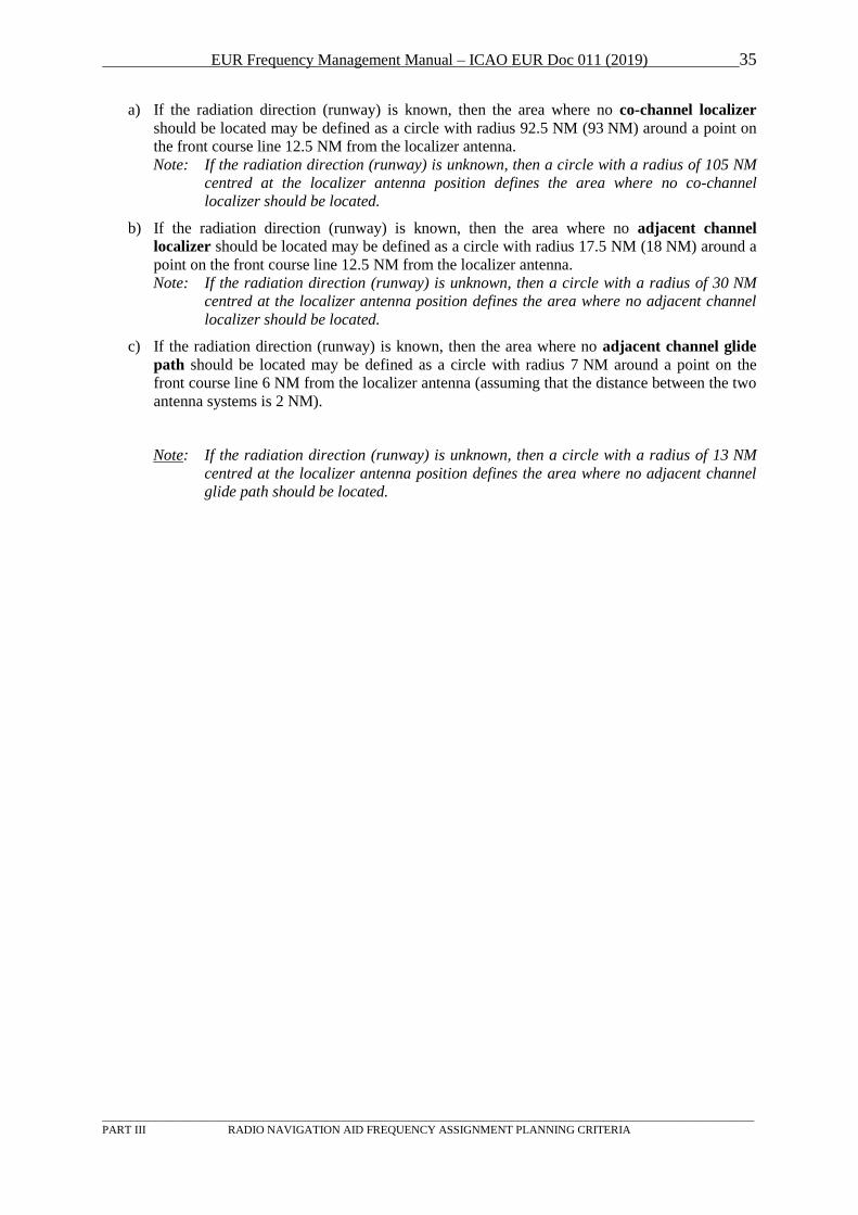
EUR Frequency Management Manual – ICAO EUR Doc 011 (2019) 35
_________________________________________________________________________________________________________________
PART III RADIO NAVIGATION AID FREQUENCY ASSIGNMENT PLANNING CRITERIA
a) If the radiation direction (runway) is known, then the area where no co-channel localizer
should be located may be defined as a circle with radius 92.5 NM (93 NM) around a point on
the front course line 12.5 NM from the localizer antenna.
Note: If the radiation direction (runway) is unknown, then a circle with a radius of 105 NM
centred at the localizer antenna position defines the area where no co-channel
localizer should be located.
b) If the radiation direction (runway) is known, then the area where no adjacent channel
localizer should be located may be defined as a circle with radius 17.5 NM (18 NM) around a
point on the front course line 12.5 NM from the localizer antenna.
Note: If the radiation direction (runway) is unknown, then a circle with a radius of 30 NM
centred at the localizer antenna position defines the area where no adjacent channel
localizer should be located.
c) If the radiation direction (runway) is known, then the area where no adjacent channel glide
path should be located may be defined as a circle with radius 7 NM around a point on the
front course line 6 NM from the localizer antenna (assuming that the distance between the two
antenna systems is 2 NM).
Note: If the radiation direction (runway) is unknown, then a circle with a radius of 13 NM
centred at the localizer antenna position defines the area where no adjacent channel
glide path should be located.
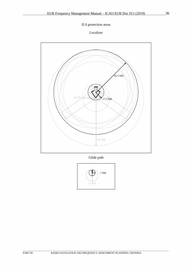
EUR Frequency Management Manual – ICAO EUR Doc 011 (2019) 36
_________________________________________________________________________________________________________________
PART III RADIO NAVIGATION AID FREQUENCY ASSIGNMENT PLANNING CRITERIA
ILS protection areas
Localizer
Glide path
92.5 NM
105 NM
30 NM 17.5 NM
7 NM
13 NM
EUR Frequency Management Manual – ICAO EUR Doc 011 (2019) 37
_________________________________________________________________________________________________________________
PART III RADIO NAVIGATION AID FREQUENCY ASSIGNMENT PLANNING CRITERIA
3 VOR
3.1 General
3.1.1 The band 108 - 112 MHz is used by ILS Localizer and VOR, on different channels, while the
band 112 - 118 MHz is used only by VOR. Within the band 108 - 112 MHz, all channels on
even multiples of 100 kHz (108.20, 108.40, ...) are used for VOR. Normally channels spaced
100 kHz are used, however, in congested areas also the intermediate channels (50 kHz) may be
used. The VOR channels in this sub-band are usually used for terminal VOR, with short range.
Within the 112 - 118 MHz portion of the band all channels (100 and 50 kHz) are available for
VOR services.
Note : In the EUR region, for the avoidance of harmful interference, it is not permitted for a VOR
facility to operate, even on a temporary basis, on a frequency allotted to ILS localizers.
3.1.2 References to documents:
- Annex 10, Volume I, paragraphs 3.3.2
(frequency band, channel spacing);
- Annex 10, Attachment C to Volume I, paragraphs 3.4 and 3.5
(geographical separations);
- European Region Air Navigation Plan (Doc 7754), Volume I, Basic ANP, Part IV,
paragraphs 42-44
(geographical separation criteria, channel spacing and harmonics;
- European Region Air Navigation Plan (Doc 7754), Volume II, FASID, Part IV, paragraphs
22, 24
(principles and criteria).
3.1.3 The DOC of a VOR can typically vary from 25 NM to approximately 100 NM and the protected
altitude up to between 10 000 feet and 60 000 feet. Any unwanted signal must be at least 20 dB
lower than the signal from the wanted station. Sectorization of the coverage may be used, in this
case the range is different in different directions according to a system described in Appendix A
to Part III. Information of the designated operational coverage of each station is available from
Table COM 3 and published accordingly in the national AIP. Both the co-channel and the first
adjacent channels on each side are considered in the planning.
3.1.4 The co-ordination should also take into account the risk of interference from broadcasting
stations in the band 87.5-108 MHz, due to interference caused by unwanted emissions into the
aeronautical band or generated in the airborne receiver. Rules for this are available from the
Recommendation ITU-R SM.1009-1 “Compatibility between the sound-broadcasting service in
the band of about 87 - 108 MHz and the aeronautical services in the band 108 - 118 MHz”.
3.1.5 Co-ordination should as a minimum be made with States within a radius of approximately 400 -
500 NM, and also be made with the authority responsible for the analysis of the broadcasting
versus aeronautical situation.
3.1.6 Information on the planning of identifications can be found in section 7 below.
3.2 Basic Principles
3.2.1 Frequencies for VOR facilities should be selected at 50 kHz points, in accordance with
Annex 10, Volume I, 3.3.2.1 and Volume V, 4.2.1, 4.2.3 and 4.2.3.1. The associated DME
channels should be selected from Table A of Chapter 3 of Volume I.
EUR Frequency Management Manual – ICAO EUR Doc 011 (2019) 38
_________________________________________________________________________________________________________________
PART III RADIO NAVIGATION AID FREQUENCY ASSIGNMENT PLANNING CRITERIA
3.2.2 Where the designated operational range of a given station is not the same throughout 360°, the
angular limits of sectorization in range should be indicated in accordance with the method
described in Appendix A to Part III.
3.3 Frequency Assignment Planning Criteria
3.3.1 Introduction
Note: 113.250 MHz is reserved for possible future use as a VDL Mode 4 CSC. Assignments of VOR on this
frequency are not permitted until further notice.
3.3.1.1 The criteria for VOR frequency planning are based on paragraph 3.4 of Attachment C of
Volume I, Annex 10.
3.3.1.2 The 1976 EUR FCB Meeting agreed that, for VOR frequency planning purposes, the attached
Tables should be used in replacement of existing material, for the calculation of geographical
separation between VOR in the co-channel and adjacent channel cases in the EUR Region (cf.
Resolution No. 10).
3.3.1.3 These tables take into account, as appropriate:
a) The fact that 20 dB has been retained by the EUR FCB as the planned minimum D/U signal
strength ratio, within the protected coverage of EUR VOR facilities;
b) The relative VOR effective radiated power, covering power ratios up to 100 (i.e. ±20 dB), so
that account can be taken of VORs whose ERP varies, for example, from 200 W to 2 W;
c) The adjacent channel protection ratio corresponding to the particular ground and airborne
equipment situations.
3.3.1.4 As the geographical separations have been calculated on the basis of a typical ground VOR
antenna and its vertical directivity taken into account, it is only necessary in the case of VOR
facilities having typical ground VOR antennas to specify the total radiated power. The
pertinent characteristics of the assumed ground VOR antenna are given in 3.3.2.2 and such
characteristics are typical for range calculation purposes of existing known VOR ground
facilities having single dipoles located above the counterpoise and for which the elevation
angle of maximum radiation is about 25 to 30 degrees.
3.3.1.5 In the case of any facilities where the vertical pattern substantially differs from that of a single
dipole (i.e. where a two-element antenna may be used to enhance the lower angle radiation),
the radiated power could be suitably adjusted for the angles of elevation of most interest. A
factor of 3 to 4 dB would appear to be appropriate, i.e. for geographical separation purposes a
VOR with a two-element antenna and having a total radiated power of 25 W would be
considered as having a total radiated power of 50/65 W.
3.3.1.6 Criteria for geographical separation between ILS and VOR facilities operating in the band
108 - 112 MHz can be found in paragraph 3.5 of Attachment C to Volume I of Annex 10.
3.3.2 Desired to Undesired Signal Ratio Contours
3.3.2.1 If two VOR facilities of equal radiated power are separated in distance, it is possible to
construct desired/undesired facility signal ratio contours. Figure 1 shows the contours that will
be obtained when the desired facility is at 0 NM and the undesired facility at 371 km
(200 NM) (i.e. a geographical separation of 200 NM). The 20 dB contour is relevant to the co-
channel case, the -34 dB contour relevant to the 50 kHz adjacent channel case (9960
EUR Frequency Management Manual – ICAO EUR Doc 011 (2019) 39
_________________________________________________________________________________________________________________
PART III RADIO NAVIGATION AID FREQUENCY ASSIGNMENT PLANNING CRITERIA
harmonics in conformity with Annex 10), and the -20 dB contour relevant to the 50 kHz
adjacent channel case (9960 Hz harmonics not in conformity with Annex 10). For other
geographical separation distances the D/U ratio contours follow a similar pattern.
3.3.2.2 Also shown on Figure 1 is a "nominal range curve". The nominal range curve shows the range
and altitude at which a power density of -113 dBW/m2 will be obtained at 108 MHz for a
radiated power of 100 W (20 dBW), the ground VOR facility being assumed to have a circular
horizontal pattern and a vertical pattern similar to a dipole 1.22 m (4 ft) above a 16 m (52 ft)
diameter counterpoise which in turn is assumed to be 4.83 m (16 ft) above ground level.
Under favourable conditions (e.g. path, airborne receiver sensitivity greater than that
assumed), the range obtainable may exceed the "nominal range" by a factor of 1.15 or so. This
greater range approximates to the horizon range based on a true earth radius.
3.3.2.3 The following deductions can be made from Figure 1:
a) +20 dB Contour. This is applicable to the co-channel case. For the geographical separation
distance of 371 km (200 NM), it would be possible to have cylindrical service volumes of
93 km (50 NM), 11278 m (37000 ft) or 139 km (75 NM), 3353 m (11000 ft). It will be noted
that in the co-channel case, because of the direction of the +20 dB contour, the highest altitude
to be protected is the controlling factor in determining the geographical separation distance.
b) -20 and -34 dB contours. These are applicable to adjacent channel cases. Because the direction
of the slope of the contour is the opposite of the co-channel case, the lowest altitude to be
protected is the controlling factor. For a given distance separation, it is only necessary to
protect those altitudes above the "horizon" curve because at lower altitudes there will be
insufficient signal level to reliably actuate the airborne receiver (see 3.3.2.2 above).
3.3.3 The Co-channel Case
3.3.3.1 The geographical separation distances, at Tables 1 to 9 inclusive, have been derived from the
formulas given at 3.4.5 of Attachment C to Volume I of ICAO Annex 10 and reproduced here,
for easy reference. When using geographical separation distances derived from ICAO Annex
10, particular note should be taken of 3.4.7 of Attachment C to Volume I which states that "the
application of the figures will only be correct within the limitations set by those (the)
assumptions. The assumptions include that the change of field strength with distance (Factor
"S") at various altitudes of reception is only valid for angles of elevation at the VOR of up to
about 5 degrees, but above the radio line of sight". In practice account need only be taken of
this limitation for short range/high altitude facilities, where the altitude component is 15240 m
(50000 ft) and above, and long range/high altitude facilities, where the altitude component is
12192 m (40000 ft) and above. Increased geographical separation distances (marked + in the
tables) are recommended to assure adequate protection for the combinations specified, i.e.
where the elevation angle exceeds 5 degrees. Decreased geographical separation distances
(marked *) may be used for the combinations specified due to the higher rate of change of
field strength (Factor "S") at or near the horizon.
EUR Frequency Management Manual – ICAO EUR Doc 011 (2019) 40
_________________________________________________________________________________________________________________
PART III RADIO NAVIGATION AID FREQUENCY ASSIGNMENT PLANNING CRITERIA
Example:
Facility 1: DOC 25 NM / 10000 ft, 100 W (20 dBW) EIRP
Facility 2: DOC 100 NM / 50000 ft 400 W (26 dBW) EIRP
D/U = 20 dB
DB1B = 25 NM
DB2B = 100 NM
K = -6 dB (20 dBW - 26 dBW)
S (10000 ft) = 0.43 dB/NM (Table C-3, Attachment C to Volume I of Annex 10)
S (50000 ft) = 0.18 dB/NM (Table C-3, Attachment C to Volume I of Annex 10)
Separation distance: the greater of 2DB1B + (D/U-K)/S or 2DB2B + (D/U+K)/S:
2*25+(20+6)/0.43 NM= 110 NM or 2*100+(20-6)/0.18 NM = 278 NM
Required minimum separation distance = 278 NM
3.3.4 The Adjacent Channel Case
3.3.4.1 Tables 10 and 11 give the necessary geographical separation of adjacent channel facilities for
the following cases:
a) 50 kHz channel spacing, harmonic levels low (Table 10)
b) 50 kHz channel spacing, harmonic levels high (Table 11)
The undesired facility should always be outside the DOC of the desired facility.
3.3.4.2 In each table, the necessary geographical separation has been derived from the formula at
3.4.5, Attachment C to Volume I of ICAO Annex 10, in accordance with the method given in
3.3.4.3 below.
3.3.4.3 The derivation of adjacent channel geographical separation distances requires that account be
taken of both the range and the lowest altitude at which the provision of the necessary
desired/undesired (D/U) field strength ratio is required. The lowest altitude at which protection
is to be provided is assumed to be that height corresponding to the horizon distance (based on
true earth radius) for the range in question, experience having shown that this horizon distance
is the normal maximum range achievable (see 3.3.2.2 and 3.3.2.3 b) above).
The horizon distance for a true earth radius is given by the formula:
D = H13.1
where H is in feet, D in NM.
This formula can be re-arranged as follows :
H = 0.9 D2
3.3.4.4 The following Table gives for the ranges specified, values of H together with corresponding S
values to be inserted in the ICAO adjacent channel geographical separation formula:
EUR Frequency Management Manual – ICAO EUR Doc 011 (2019) 41
_________________________________________________________________________________________________________________
PART III RADIO NAVIGATION AID FREQUENCY ASSIGNMENT PLANNING CRITERIA
D km(NM) H m (ft) S (dB/NM)
46 km (25) 171 m (560) 1.0
74 km (40) 439 m (1 440) 1.0
111 km (60) 987 m (3 240) 0.65
148 km (80) 1 756 m (5 760) 0.55
185 km (100) 2 743 m (9 000) 0.44
278 km (150) 6 172 m (20 250) 0.28
333 km (180) 8 888 m (29 160) 0.23
380 km (205) 11 521 m ( 37 800) 0.20
426 km (230) 14 511 m (47 610) 0.18
The above values D and S have been used in the derivation of geographical separation distances based
on the use of the adjacent channel geographical separation formula given at 3.4.5 of Attachment C to
Volume I of ICAO Annex 10.
Example:
Facility 1: DOC 25 NM / 10000 ft, 100 W (20 dBW) EIRP
Facility 2: DOC 100 NM / 50000 ft 400 W (26 dBW) EIRP
D/U = -34 dB (Paragraph 3.4.6.1 b), Attachment C to Volume I of Annex 10)
D1 = 25 NM
D2 = 100 NM
K = -6 dB (20 dBW - 26 dBW)
S (25 NM) = 1.00 dB/NM (Paragraph 3.3.4.4)
S (100 NM) = 0.44 dB/NM (Paragraph 3.3.4.4)
Separation distance: the greater of 2D1 - (34+K)/S or 2D2 - (34-K)/S:
2*25-(34-6)/1.00 NM= 22 NM or 2*100-(34+6)/0.44 NM = 109 NM
Required minimum separation distance: 109 NM.
3.3.5 Sectorization
3.3.5.1 Application of the calculation methods described above may produce incorrect results if
sectorization (key-holing) is used. The figure below can be used to explain the problem:
Consider A to be the desired VOR facility and B the undesired one. The “Critical Point” is most
exposed to interference from facility B because it is the point of the DOC of facility A which is nearest
to transmitter B. Its vulnerability is further enhanced by the distance from facility A which is the
maximum possible within the DOC of A.
3.3.5.2 The correct assessment of compatibility for facility A requires the following calculations:
Co-channel:
Minimum separation distance between “Critical Point” and transmitter B: D1+(20-K)/S;
(this is derived from a subtraction of D1 from 2D1+(20-K)/S).
Adjacent channel:
Minimum separation distance between “ Critical Point” and transmitter B: D1-(34+K)/S;
(this is derived from a subtraction of D1 from 2D1-(34+K)/S);
where
D1 = range of facility A at the “Critical Point”.
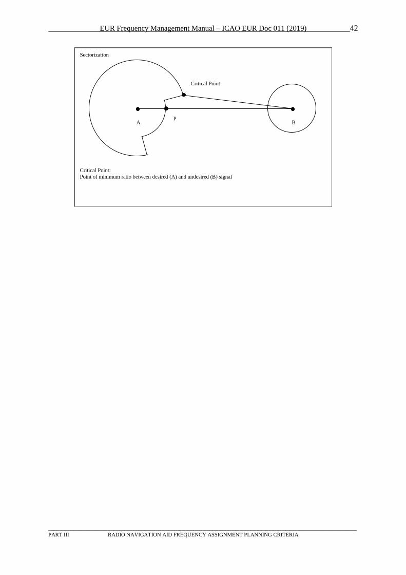
EUR Frequency Management Manual – ICAO EUR Doc 011 (2019) 42
_________________________________________________________________________________________________________________
PART III RADIO NAVIGATION AID FREQUENCY ASSIGNMENT PLANNING CRITERIA
Critical Point
A BP
Sectorization
Critical Point:
Point of minimum ratio between desired (A) and undesired (B) signal
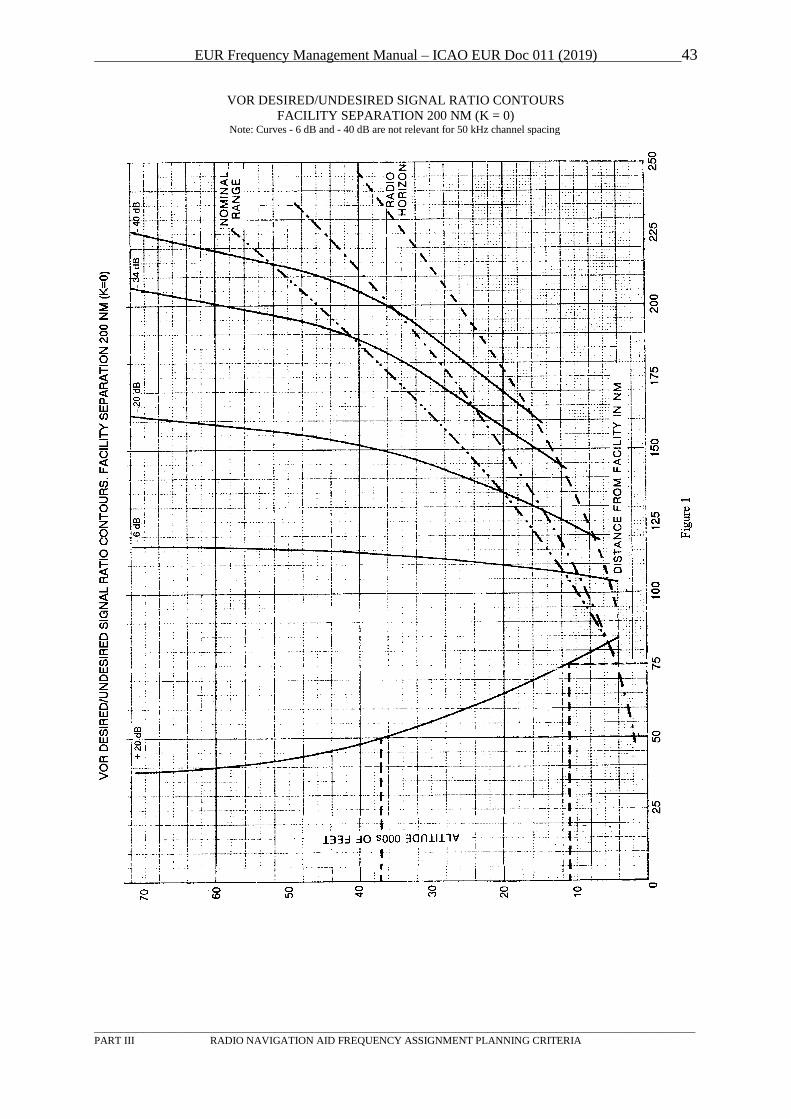
EUR Frequency Management Manual – ICAO EUR Doc 011 (2019) 43
_________________________________________________________________________________________________________________
PART III RADIO NAVIGATION AID FREQUENCY ASSIGNMENT PLANNING CRITERIA
VOR DESIRED/UNDESIRED SIGNAL RATIO CONTOURS
FACILITY SEPARATION 200 NM (K = 0) Note: Curves - 6 dB and - 40 dB are not relevant for 50 kHz channel spacing
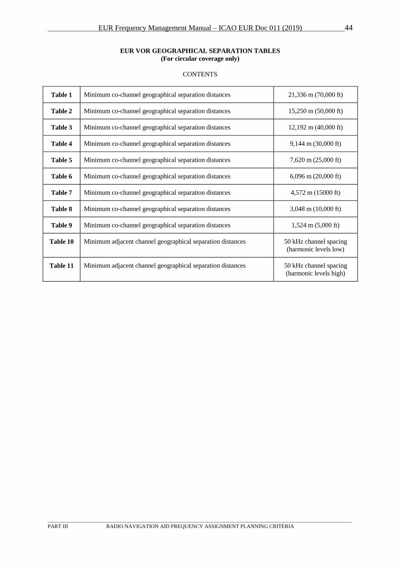
EUR Frequency Management Manual – ICAO EUR Doc 011 (2019) 44
_________________________________________________________________________________________________________________
PART III RADIO NAVIGATION AID FREQUENCY ASSIGNMENT PLANNING CRITERIA
EUR VOR GEOGRAPHICAL SEPARATION TABLES
(For circular coverage only)
CONTENTS
Table 1 Minimum co-channel geographical separation distances 21,336 m (70,000 ft)
Table 2 Minimum co-channel geographical separation distances 15,250 m (50,000 ft)
Table 3 Minimum co-channel geographical separation distances 12,192 m (40,000 ft)
Table 4 Minimum co-channel geographical separation distances 9,144 m (30,000 ft)
Table 5 Minimum co-channel geographical separation distances 7,620 m (25,000 ft)
Table 6 Minimum co-channel geographical separation distances 6,096 m (20,000 ft)
Table 7 Minimum co-channel geographical separation distances 4,572 m (15000 ft)
Table 8 Minimum co-channel geographical separation distances 3,048 m (10,000 ft)
Table 9 Minimum co-channel geographical separation distances 1,524 m (5,000 ft)
Table 10 Minimum adjacent channel geographical separation distances 50 kHz channel spacing
(harmonic levels low)
Table 11 Minimum adjacent channel geographical separation distances 50 kHz channel spacing
(harmonic levels high)
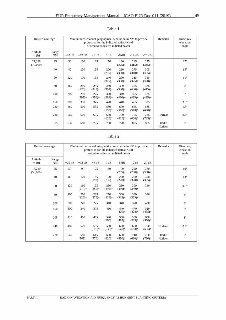
EUR Frequency Management Manual – ICAO EUR Doc 011 (2019) 45
_________________________________________________________________________________________________________________
PART III RADIO NAVIGATION AID FREQUENCY ASSIGNMENT PLANNING CRITERIA
Table 1
Desired coverage Minimum co-channel geographical separation in NM to provide
protection for the indicated ratios (K) of desired to undesired radiated power
Remarks Direct ray
elevation angle
Altitude
m (ft)
Range
NM +20 dB +12 dB +6 dB 0 dB -6 dB -12 dB -20 dB
21,336 (70,000)
25 50 100 125 170 190 (225)+
245 (315)+
275 (345)+
27°
40 80 130 155 200
(255)+
220
(300)+
275
(340)+
305
(365)+
15°
60 120 170 195 240
(325)+
260
(350)+
315
(375)+
345
(390)+
11°
80 160 210 (270)+
235 (325)+
280 (360)+
300 (380)+
355 (400)+
385 (415)+
9°
100 200 250
(295)+
275
(350)+
320
(380)+
340
(410)+
395
(425)+
425
(435)+
6°
150 300 350 375 420 440 495 525 3.5°
230 460 510 535 580
(555)*
600
(560)*
655
(570)*
685
(600)*
1.3°
280 560 610 635 680
(620)*
700
(625)*
755
(680)*
785
(725)*
Horizon 0.4°
315 630 680 705 750 770 825 855 Radio Horizon
0°
Table 2
Desired coverage Minimum co-channel geographical separation in NM to provide
protection for the indicated ratios (K) of desired to undesired radiated power
Remarks Direct ray
elevation angle
Altitude
m (ft)
Range
NM +20 dB +12 dB +6 dB 0 dB -6 dB -12 dB -20 dB
15,240 (50,000)
25 50 90 125 160 190 (205)+
220 (260)+
270 (300)+
19°
40 80 120 155 (190)+
190 (235)+
220 (270)+
250 (320)+
300 (335)+
13°
60 120 160 (210)+
195 (250)+
230 (290)+
260 (310)+
290 (330)+
340 9.5°
80 160 200 (225)+
235 (275)+
270 (310)+
300 (335)+
330 (355)+
380 6°
100 200 240 275 310 340 370 420 4°
150 300 340 375 410 440 (420)*
470 (428)*
520 (435)*
2°
205 410 450 485 520 (490)*
550 (495)*
580 (505)*
630 (560)*
1°
240 480 520 555 (525)*
590 (535)*
620 (540)*
650 (600)*
700 (655)*
Horizon 0.4°
270 540 580 (565)*
615 (570)*
650 (620)*
680 (650)*
710 (680)*
760 (730)*
Radio Horizon
0°
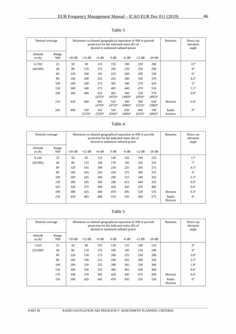
EUR Frequency Management Manual – ICAO EUR Doc 011 (2019) 46
_________________________________________________________________________________________________________________
PART III RADIO NAVIGATION AID FREQUENCY ASSIGNMENT PLANNING CRITERIA
Table 3
Desired coverage Minimum co-channel geographical separation in NM to provide
protection for the indicated ratios (K) of desired to undesired radiated power
Remarks Direct ray
elevation angle
Altitude
m (ft)
Range
NM +20 dB +12 dB +6 dB 0 dB -6 dB -12 dB -20 dB
12.592 25 50 90 125 155 190 220 260 15°
(40.000) 40 80 120 155 185 220 250 290 9°
60 120 160 195 225 260 290 330 6°
80 160 200 235 265 300 330 370 4.2°
100 200 240 275 305 340 370 410 3°
150 300 340 375 405 440 470 510 1.5°
180 360 400 435 (425)*
465 (435)*
500 (440)*
530 (450)*
570 (485)*
0.9°
210 420 460 495 (470)*
525 (475)*
560 (480)*
590 (535)*
630 (580)*
Horizon 0.4°
245 490 530
(515)*
565 (520)*
595 (560)*
630 (600)*
660 (635)*
700 (680)*
Radio
horizon
0°
Table 4
Desired coverage Minimum co-channel geographical separation in NM to provide protection for the indicated ratios (K) of
desired to undesired radiated power
Remarks Direct ray elevation
angle
Altitude
m (ft)
Range
NM +20 dB +12 dB +6 dB 0 dB -6 dB -12 dB -20 dB
9.144 25 50 85 110 140 165 190 225 11°
(30.000) 40 80 115 140 170 195 220 235 7°
60 120 165 180 210 235 260 275 4.5°
80 160 205 220 250 275 300 315 3°
100 200 245 260 290 315 340 355 2.3°
150 300 345 360 390 415 440 455 0.9°
165 330 375 390 420 445 470 485 0.6°
190 380 425 440 470 495 520 535 Horizon 0.3°
210 420 465 480 510 535 560 575 Radio Horizon
0°
Table 5
Desired coverage Minimum co-channel geographical separation in NM to provide protection for the indicated ratios (K) of
desired to undesired radiated power
Remarks Direct ray elevation
angle
Altitude
m (ft)
Range
NM +20 dB +12 dB +6 dB 0 dB -6 dB -12 dB -20 dB
7,620 25 50 80 105 130 155 180 210 9°
(25,000) 40 80 110 135 160 185 210 240 6°
60 120 150 175 200 225 250 280 3.8°
80 160 190 215 240 265 290 320 2.5°
100 200 230 255 280 305 330 360 1.8°
150 300 330 355 380 405 430 460 0.6°
170 340 370 395 420 445 470 500 Horizon 0.4°
195 390 420 445 470 495 520 550 Radio
Horizon
0°
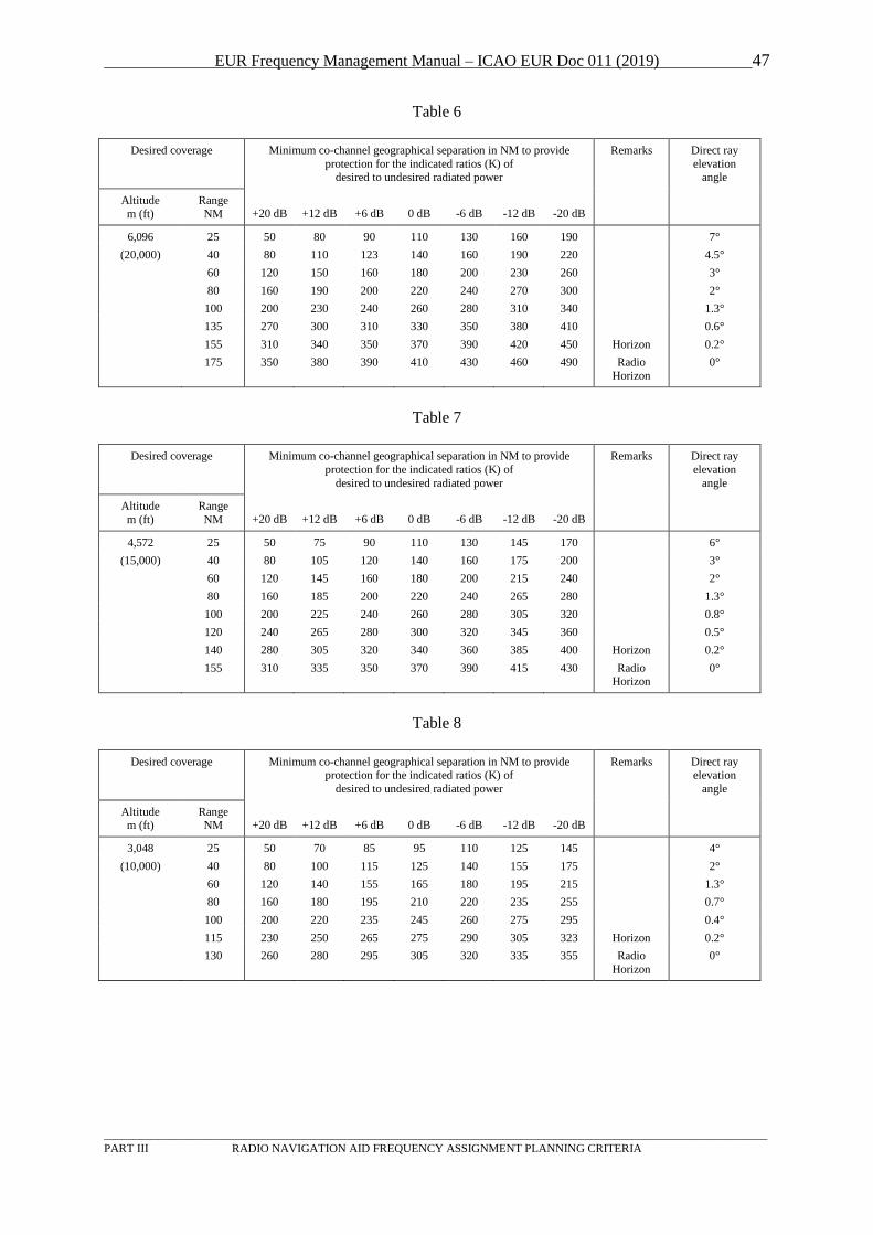
EUR Frequency Management Manual – ICAO EUR Doc 011 (2019) 47
_________________________________________________________________________________________________________________
PART III RADIO NAVIGATION AID FREQUENCY ASSIGNMENT PLANNING CRITERIA
Table 6
Desired coverage Minimum co-channel geographical separation in NM to provide
protection for the indicated ratios (K) of desired to undesired radiated power
Remarks Direct ray
elevation angle
Altitude
m (ft)
Range
NM +20 dB +12 dB +6 dB 0 dB -6 dB -12 dB -20 dB
6,096 25 50 80 90 110 130 160 190 7°
(20,000) 40 80 110 123 140 160 190 220 4.5°
60 120 150 160 180 200 230 260 3°
80 160 190 200 220 240 270 300 2°
100 200 230 240 260 280 310 340 1.3°
135 270 300 310 330 350 380 410 0.6°
155 310 340 350 370 390 420 450 Horizon 0.2°
175 350 380 390 410 430 460 490 Radio
Horizon
0°
Table 7
Desired coverage Minimum co-channel geographical separation in NM to provide
protection for the indicated ratios (K) of
desired to undesired radiated power
Remarks Direct ray
elevation
angle
Altitude
m (ft)
Range
NM +20 dB +12 dB +6 dB 0 dB -6 dB -12 dB -20 dB
4,572 25 50 75 90 110 130 145 170 6°
(15,000) 40 80 105 120 140 160 175 200 3°
60 120 145 160 180 200 215 240 2°
80 160 185 200 220 240 265 280 1.3°
100 200 225 240 260 280 305 320 0.8°
120 240 265 280 300 320 345 360 0.5°
140 280 305 320 340 360 385 400 Horizon 0.2°
155 310 335 350 370 390 415 430 Radio Horizon
0°
Table 8
Desired coverage Minimum co-channel geographical separation in NM to provide protection for the indicated ratios (K) of
desired to undesired radiated power
Remarks Direct ray elevation
angle
Altitude m (ft)
Range NM +20 dB +12 dB +6 dB 0 dB -6 dB -12 dB -20 dB
3,048 25 50 70 85 95 110 125 145 4°
(10,000) 40 80 100 115 125 140 155 175 2°
60 120 140 155 165 180 195 215 1.3°
80 160 180 195 210 220 235 255 0.7°
100 200 220 235 245 260 275 295 0.4°
115 230 250 265 275 290 305 323 Horizon 0.2°
130 260 280 295 305 320 335 355 Radio
Horizon
0°
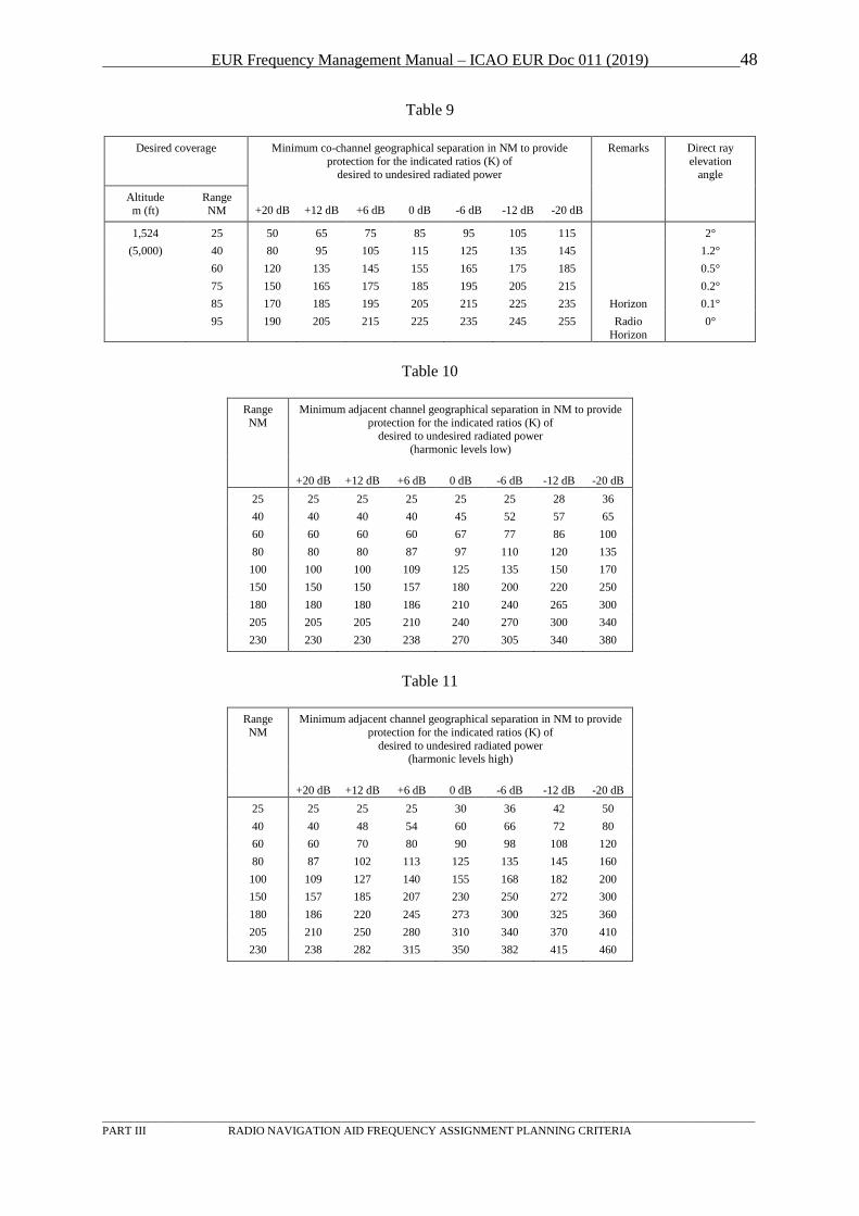
EUR Frequency Management Manual – ICAO EUR Doc 011 (2019) 48
_________________________________________________________________________________________________________________
PART III RADIO NAVIGATION AID FREQUENCY ASSIGNMENT PLANNING CRITERIA
Table 9
Desired coverage Minimum co-channel geographical separation in NM to provide
protection for the indicated ratios (K) of desired to undesired radiated power
Remarks Direct ray
elevation angle
Altitude
m (ft)
Range
NM +20 dB +12 dB +6 dB 0 dB -6 dB -12 dB -20 dB
1,524 25 50 65 75 85 95 105 115 2°
(5,000) 40 80 95 105 115 125 135 145 1.2°
60 120 135 145 155 165 175 185 0.5°
75 150 165 175 185 195 205 215 0.2°
85 170 185 195 205 215 225 235 Horizon 0.1°
95 190 205 215 225 235 245 255 Radio
Horizon
0°
Table 10
Range
NM
Minimum adjacent channel geographical separation in NM to provide
protection for the indicated ratios (K) of desired to undesired radiated power
(harmonic levels low)
+20 dB +12 dB +6 dB 0 dB -6 dB -12 dB -20 dB
25 25 25 25 25 25 28 36
40 40 40 40 45 52 57 65
60 60 60 60 67 77 86 100
80 80 80 87 97 110 120 135
100 100 100 109 125 135 150 170
150 150 150 157 180 200 220 250
180 180 180 186 210 240 265 300
205 205 205 210 240 270 300 340
230 230 230 238 270 305 340 380
Table 11
Range
NM
Minimum adjacent channel geographical separation in NM to provide
protection for the indicated ratios (K) of
desired to undesired radiated power (harmonic levels high)
+20 dB +12 dB +6 dB 0 dB -6 dB -12 dB -20 dB
25 25 25 25 30 36 42 50
40 40 48 54 60 66 72 80
60 60 70 80 90 98 108 120
80 87 102 113 125 135 145 160
100 109 127 140 155 168 182 200
150 157 185 207 230 250 272 300
180 186 220 245 273 300 325 360
205 210 250 280 310 340 370 410
230 238 282 315 350 382 415 460
EUR Frequency Management Manual – ICAO EUR Doc 011 (2019) 49
_________________________________________________________________________________________________________________
PART III RADIO NAVIGATION AID FREQUENCY ASSIGNMENT PLANNING CRITERIA
4 GBAS
4.1 General
4.1.1 The GNSS ground-based augmentation system (GBAS) VHF data broadcast (VDB) frequency
band is 108 to 117.975 MHz. The lowest assignable frequency is 108.025 MHz and the highest
assignable frequency is 117.950 MHz – channel spacing is 25 kHz. This band is also used for
ILS (below 112 MHz) and for VOR. GBAS VDB applies a time division multiple access
(TDMA) technique with 8 time slots which are repeated every 0.5 seconds. The signal timing is
synchronised with UTC.
Note: 113.250 MHz is reserved for possible future use as a VDL Mode 4 CSC. Assignments of GBAS on the
frequencies 113.225, 113.250 and 113.275 MHz are not permitted until further notice.
4.1.2 References to documents:
- Annex 10, Volume I, paragraph 3.7.3.5
(coverage, carrier frequency, channelling, field strength);
- Annex 10, Appendix B to Volume I, paragraph 3.6.8.2.2.5-7
(co- and adjacent channel rejection requirements);
- Annex 10, Attachment D to Volume I, paragraph 7.2.1 and 7.9
(frequency planning, geographical separation, adjacent frequency requirements,
assignment of reference path data selector and reference station data selector);
- Annex 10, Volume V, paragraph 4.2
(use of the band 108 – 117.975 MHz).
4.1.3 The GBAS precision approach coverage is defined relative to the runway. However, it is
recommended to use an omnidirectional designated operational coverage (DOC) with a range of
23 NM and up to a height of 10000 ft above threshold. The GBAS positioning service coverage
is dependent upon the specific operations intended. Undesired signals from co-channel GBAS or
VOR stations must be at least 26 dB below the desired GBAS signal. Adjacent channels up to
±100 kHz must be considered in the compatibility assessment.
4.1.4 The risk of interference from FM broadcasting stations in the band 87.5 – 108 MHz caused by
unwanted emissions into the aeronautical band or generated in the airborne receiver should be
taken into account. The relevant Recommendation for GBAS is ITU-R SM.1841.
4.1.5 Co-ordination should be made with States within a radius of about 500 NM and also with the
authority responsible for compatibility between FM broadcasting and aeronautical radio
navigation services.
4.1.6 Besides the frequency, co-ordination must also take into account reference path data selectors
and reference station data selectors (RPDS and RSDS) and time slots.
4.1.7 Information on the planning of identifications can be found in section 7 below.
4.1.8 The prerequisite for any D/U calculation to be valid is that the minimal receive power is
achieved at all points throughout the coverage.
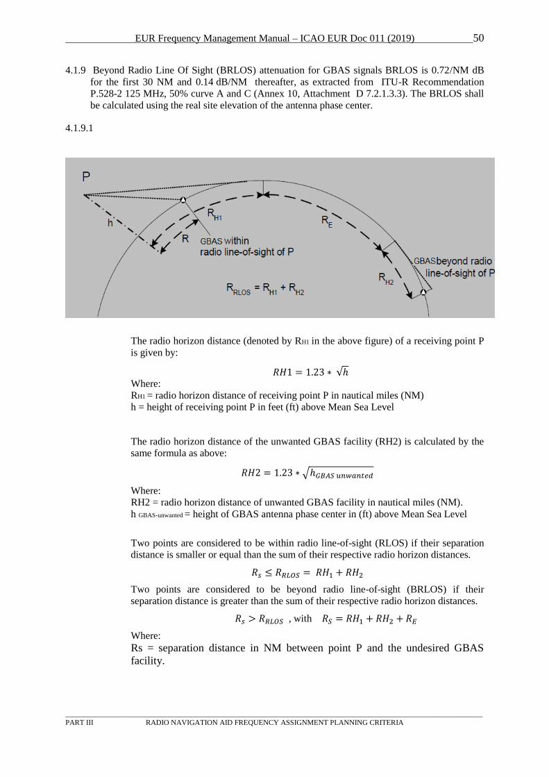
EUR Frequency Management Manual – ICAO EUR Doc 011 (2019) 50
_________________________________________________________________________________________________________________
PART III RADIO NAVIGATION AID FREQUENCY ASSIGNMENT PLANNING CRITERIA
4.1.9 Beyond Radio Line Of Sight (BRLOS) attenuation for GBAS signals BRLOS is 0.72/NM dB
for the first 30 NM and 0.14 dB/NM thereafter, as extracted from ITU-R Recommendation
P.528-2 125 MHz, 50% curve A and C (Annex 10, Attachment D 7.2.1.3.3). The BRLOS shall
be calculated using the real site elevation of the antenna phase center.
4.1.9.1
The radio horizon distance (denoted by R BH1 in the above figure) of a receiving point P
is given by:
𝑅𝐻1 = 1.23 ∗ √ℎ Where:
RBH1 B= radio horizon distance of receiving point P in nautical miles (NM)
h = height of receiving point P in feet (ft) above Mean Sea Level
The radio horizon distance of the unwanted GBAS facility (RH2) is calculated by the
same formula as above:
𝑅𝐻2 = 1.23 ∗ √ℎ𝐺𝐵𝐴𝑆 𝑢𝑛𝑤𝑎𝑛𝑡𝑒𝑑
Where:
RH2 = radio horizon distance of unwanted GBAS facility in nautical miles (NM).
h GBAS-unwanted = height of GBAS antenna phase center in (ft) above Mean Sea Level
Two points are considered to be within radio line-of-sight (RLOS) if their separation
distance is smaller or equal than the sum of their respective radio horizon distances.
𝑅𝑠 ≤ 𝑅𝑅𝐿𝑂𝑆 = 𝑅𝐻1 + 𝑅𝐻2
Two points are considered to be beyond radio line-of-sight (BRLOS) if their
separation distance is greater than the sum of their respective radio horizon distances.
𝑅𝑠 > 𝑅𝑅𝐿𝑂𝑆 , with 𝑅𝑆 = 𝑅𝐻1 + 𝑅𝐻2 + 𝑅𝐸
Where:
Rs = separation distance in NM between point P and the undesired GBAS
facility.
EUR Frequency Management Manual – ICAO EUR Doc 011 (2019) 51
_________________________________________________________________________________________________________________
PART III RADIO NAVIGATION AID FREQUENCY ASSIGNMENT PLANNING CRITERIA
RBRLOS B= radio line-of-sight distance in NM, given the heights of point P and the
unwanted GBAS facility (= sum of radio horizon distances from height P and
hGBAS-unwanted).
RBE B= propagation distance in NM covered by diffraction (= radio path distance
separating point P from the GBAS facility minus RRLOS)
4.1.10 The EIRP of a GBAS system shall be provided as Peak Envelope Power. Since MOPS specify
the output power to be measured as mean power over a bit-sequence in the preamble, care must
be taken that the PEP are used for calculation!
EIRP PEP[dBW] = P Transmitter-Output [dBW] - A Cable loss [dBW] + G Antenna gain [dBi]
4.1.11 Polarization of GBAS systems for aviation purposes shall use horizontal polarization
(=GBAS/H).
Note: While, Annex 10 states that elliptical polarization is permissible, FMG/10 decided the standard
polarization for GBAS in Europe to be horizontal. Therefore no D/U calculation criteria for
coordination of vertical polarization (GBAS/E) are available The reasoning for allowing
elliptical polarization was that a number of US military aircraft were identified that do not
possess a horizontal polarized antenna. To provide, where necessary, service for these type of
aircraft elliptical polarization (GBAS/E) was added to Annex 10. The VDB link budget from
Annex 10, Attachment D, Table D-2 (Table 1 of this working paper) specifies the system loss for
vertical polarized aircraft systems to be a 4 dB lower than for a comparable horizontally
polarized aircraft system. Horizontally polarized signal have to be therefore 4 dB stronger then
vertical polarized signals in order to achieve the same signal strength (e.g if the horizontal
polarization transmitter has 17 dBW EIRP PEP then the vertical polarized signal requires only
13 dBW EIRP PEP).
4.1.12 Since only horizontal polarization is assumed to be in operation in the European Region, the
consideration of cross polar isolation between a purely horizontal polarized GBAS system and
a vertical polarized system, like VHF-COM-CDSB will provide significantly reduced
separation requirements. The temporary value for cross polarization isolation between
horizontal and vertical polarization is assumed to be 10 dB (Annex 10, Attachement D, 7.2.4).
4.1.13 To allow a use of Frequency Management Programs, temporary values for calculation are
given in the table below. The appropriate GBAS vertical and horizontal polarization and the
respective EIRP PEP have to be available for calculation. The temporary separation
requirements based on EIRP PEP, polarization and system GBAS, ILS and VHF-COM-CDSB,
is provided in the table below.
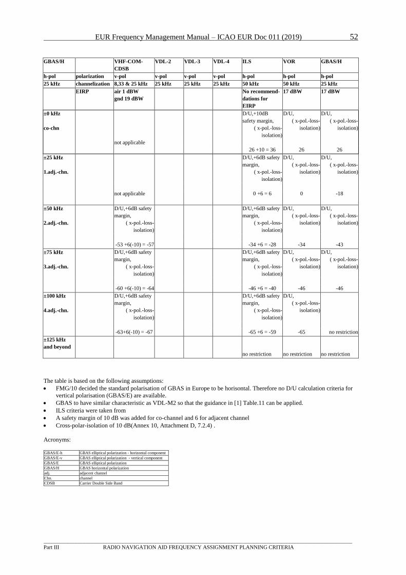
EUR Frequency Management Manual – ICAO EUR Doc 011 (2019) 52
_________________________________________________________________________________________________________________
Part III RADIO NAVIGATION AID FREQUENCY ASSIGNMENT PLANNING CRITERIA
GBAS/H VHF-COM-
CDSB
VDL-2 VDL-3 VDL-4 ILS VOR GBAS/H
h-pol polarization v-pol v-pol v-pol v-pol h-pol h-pol h-pol
25 kHz channelization 8,33 & 25 kHz 25 kHz 25 kHz 25 kHz 50 kHz 50 kHz 25 kHz
EIRP
air 1 dBW
gnd 19 dBW
No recommend-
dations for
EIRP
17 dBW 17 dBW
±0 kHz
co-chn
D/U,+10dB
safety margin,
( x-pol.-loss-
isolation)
D/U,
( x-pol.-loss-
isolation)
D/U,
( x-pol.-loss-
isolation)
not applicable
26 +10 = 36 26 26
±25 kHz
1.adj.-chn.
D/U,+6dB safety
margin,
( x-pol.-loss-
isolation)
D/U,
( x-pol.-loss-
isolation)
D/U,
( x-pol.-loss-
isolation)
not applicable 0 +6 = 6 0 -18
±50 kHz
2.adj.-chn.
D/U,+6dB safety
margin,
( x-pol.-loss-
isolation)
D/U,+6dB safety
margin,
( x-pol.-loss-
isolation)
D/U,
( x-pol.-loss-
isolation)
D/U,
( x-pol.-loss-
isolation)
-53 +6(-10) = -57 -34 +6 = -28 -34 -43
±75 kHz
3.adj.-chn.
D/U,+6dB safety
margin,
( x-pol.-loss-
isolation)
D/U,+6dB safety
margin,
( x-pol.-loss-
isolation)
D/U,
( x-pol.-loss-
isolation)
D/U,
( x-pol.-loss-
isolation)
-60 +6(-10) = -64 -46 +6 = -40 -46 -46
±100 kHz
4.adj.-chn.
D/U,+6dB safety
margin,
( x-pol.-loss-
isolation)
D/U,+6dB safety
margin,
( x-pol.-loss-
isolation)
D/U,
( x-pol.-loss-
isolation)
-63+6(-10) = -67 -65 +6 = -59 -65 no restriction
±125 kHz
and beyond
no restriction no restriction no restriction
The table is based on the following assumptions:
FMG/10 decided the standard polarisation of GBAS in Europe to be horisontal. Therefore no D/U calculation criteria for
vertical polarisation (GBAS/E) are available.
GBAS to have similar characteristic as VDL-M2 so that the guidance in [1] Table.11 can be applied.
ILS criteria were taken from
A safety margin of 10 dB was added for co-channel and 6 for adjacent channel
Cross-polar-isolation of 10 dB(Annex 10, Attachment D, 7.2.4) .
Acronyms:
GBAS/E-h GBAS elliptical polarization - horizontal component
GBAS/E-v GBAS elliptical polarization - vertical component
GBAS/E GBAS elliptical polarization
GBAS/H GBAS horizontal polarization
adj. adjacent channel
Chn. channel
CDSB Carrier Double Side Band
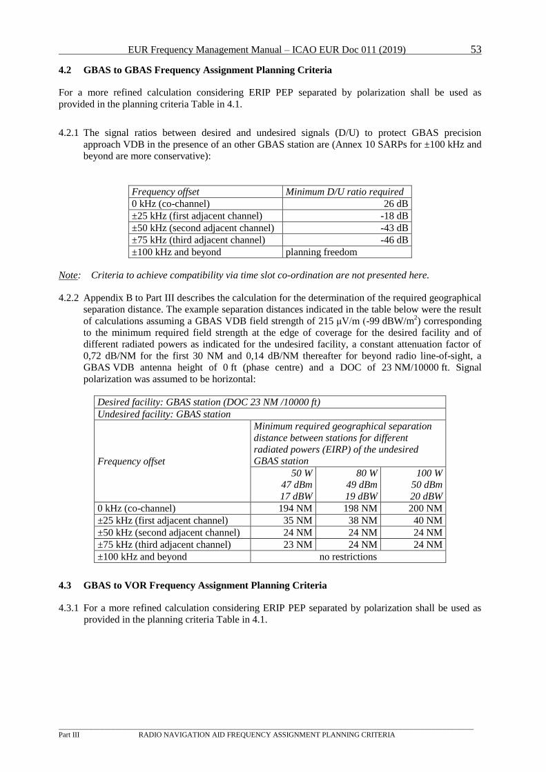
EUR Frequency Management Manual – ICAO EUR Doc 011 (2019) 53
_________________________________________________________________________________________________________________
Part III RADIO NAVIGATION AID FREQUENCY ASSIGNMENT PLANNING CRITERIA
4.2 GBAS to GBAS Frequency Assignment Planning Criteria
For a more refined calculation considering ERIP PEP separated by polarization shall be used as
provided in the planning criteria Table in 4.1.
4.2.1 The signal ratios between desired and undesired signals (D/U) to protect GBAS precision
approach VDB in the presence of an other GBAS station are (Annex 10 SARPs for ±100 kHz and
beyond are more conservative):
Frequency offset Minimum D/U ratio required
0 kHz (co-channel) 26 dB
±25 kHz (first adjacent channel) -18 dB
±50 kHz (second adjacent channel) -43 dB
±75 kHz (third adjacent channel) -46 dB
±100 kHz and beyond planning freedom
Note: Criteria to achieve compatibility via time slot co-ordination are not presented here.
4.2.2 Appendix B to Part III describes the calculation for the determination of the required geographical
separation distance. The example separation distances indicated in the table below were the result
of calculations assuming a GBAS VDB field strength of 215 μV/m (-99 dBW/mP
2P) corresponding
to the minimum required field strength at the edge of coverage for the desired facility and of
different radiated powers as indicated for the undesired facility, a constant attenuation factor of
0,72 dB/NM for the first 30 NM and 0,14 dB/NM thereafter for beyond radio line-of-sight, a
GBAS VDB antenna height of 0 ft (phase centre) and a DOC of 23 NM/10000 ft. Signal
polarization was assumed to be horizontal:
Desired facility: GBAS station (DOC 23 NM /10000 ft)
Undesired facility: GBAS station
Frequency offset
Minimum required geographical separation
distance between stations for different
radiated powers (EIRP) of the undesired
GBAS station
50 W
47 dBm
17 dBW
80 W
49 dBm
19 dBW
100 W
50 dBm
20 dBW
0 kHz (co-channel) 194 NM 198 NM 200 NM
±25 kHz (first adjacent channel) 35 NM 38 NM 40 NM
±50 kHz (second adjacent channel) 24 NM 24 NM 24 NM
±75 kHz (third adjacent channel) 23 NM 24 NM 24 NM
±100 kHz and beyond no restrictions
4.3 GBAS to VOR Frequency Assignment Planning Criteria
4.3.1 For a more refined calculation considering ERIP PEP separated by polarization shall be used as
provided in the planning criteria Table in 4.1.
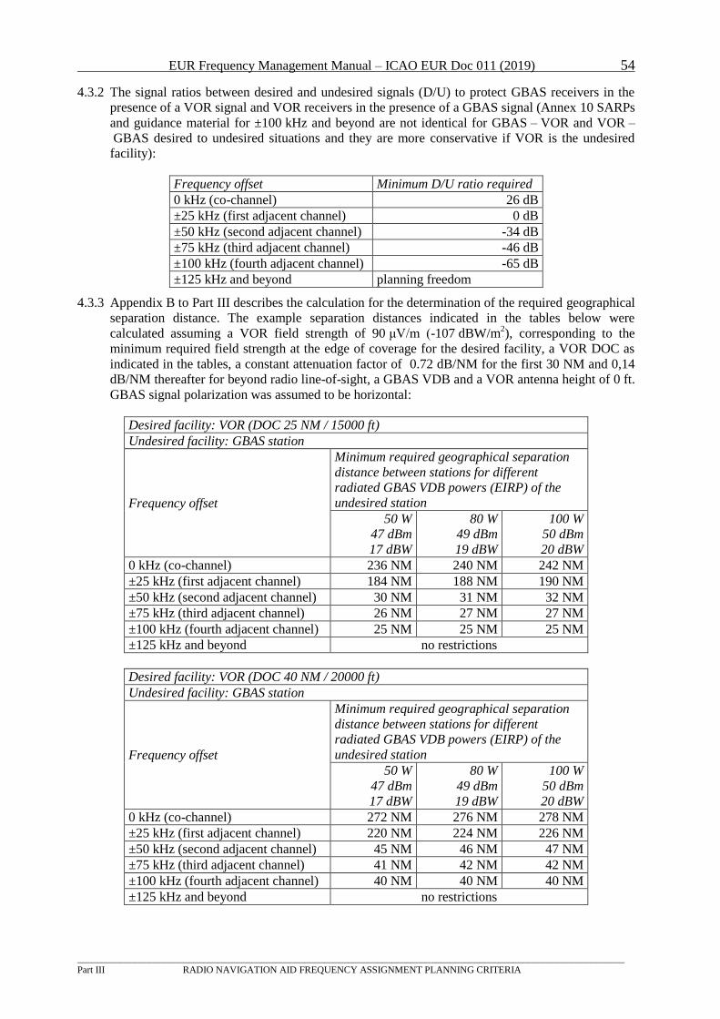
EUR Frequency Management Manual – ICAO EUR Doc 011 (2019) 54
_________________________________________________________________________________________________________________
Part III RADIO NAVIGATION AID FREQUENCY ASSIGNMENT PLANNING CRITERIA
4.3.2 The signal ratios between desired and undesired signals (D/U) to protect GBAS receivers in the
presence of a VOR signal and VOR receivers in the presence of a GBAS signal (Annex 10 SARPs
and guidance material for ±100 kHz and beyond are not identical for GBAS – VOR and VOR –
GBAS desired to undesired situations and they are more conservative if VOR is the undesired
facility):
Frequency offset Minimum D/U ratio required
0 kHz (co-channel) 26 dB
±25 kHz (first adjacent channel) 0 dB
±50 kHz (second adjacent channel) -34 dB
±75 kHz (third adjacent channel) -46 dB
±100 kHz (fourth adjacent channel) -65 dB
±125 kHz and beyond planning freedom
4.3.3 Appendix B to Part III describes the calculation for the determination of the required geographical
separation distance. The example separation distances indicated in the tables below were
calculated assuming a VOR field strength of 90 μV/m (-107 dBW/mP2P), corresponding to the
minimum required field strength at the edge of coverage for the desired facility, a VOR DOC as
indicated in the tables, a constant attenuation factor of 0.72 dB/NM for the first 30 NM and 0,14
dB/NM thereafter for beyond radio line-of-sight, a GBAS VDB and a VOR antenna height of 0 ft.
GBAS signal polarization was assumed to be horizontal:
Desired facility: VOR (DOC 25 NM / 15000 ft)
Undesired facility: GBAS station
Frequency offset
Minimum required geographical separation
distance between stations for different
radiated GBAS VDB powers (EIRP) of the
undesired station
50 W
47 dBm
17 dBW
80 W
49 dBm
19 dBW
100 W
50 dBm
20 dBW
0 kHz (co-channel) 236 NM 240 NM 242 NM
±25 kHz (first adjacent channel) 184 NM 188 NM 190 NM
±50 kHz (second adjacent channel) 30 NM 31 NM 32 NM
±75 kHz (third adjacent channel) 26 NM 27 NM 27 NM
±100 kHz (fourth adjacent channel) 25 NM 25 NM 25 NM
±125 kHz and beyond no restrictions
Desired facility: VOR (DOC 40 NM / 20000 ft)
Undesired facility: GBAS station
Frequency offset
Minimum required geographical separation
distance between stations for different
radiated GBAS VDB powers (EIRP) of the
undesired station
50 W
47 dBm
17 dBW
80 W
49 dBm
19 dBW
100 W
50 dBm
20 dBW
0 kHz (co-channel) 272 NM 276 NM 278 NM
±25 kHz (first adjacent channel) 220 NM 224 NM 226 NM
±50 kHz (second adjacent channel) 45 NM 46 NM 47 NM
±75 kHz (third adjacent channel) 41 NM 42 NM 42 NM
±100 kHz (fourth adjacent channel) 40 NM 40 NM 40 NM
±125 kHz and beyond no restrictions
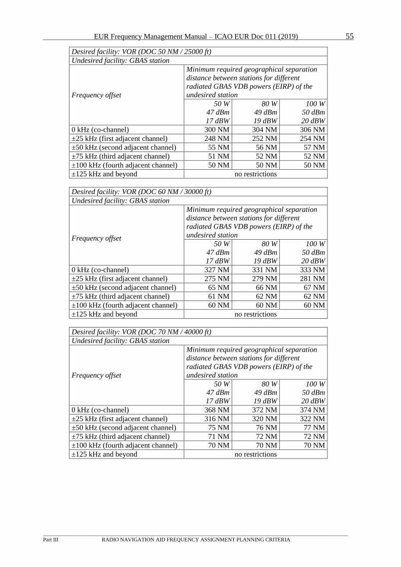
EUR Frequency Management Manual – ICAO EUR Doc 011 (2019) 55
_________________________________________________________________________________________________________________
Part III RADIO NAVIGATION AID FREQUENCY ASSIGNMENT PLANNING CRITERIA
Desired facility: VOR (DOC 50 NM / 25000 ft)
Undesired facility: GBAS station
Frequency offset
Minimum required geographical separation
distance between stations for different
radiated GBAS VDB powers (EIRP) of the
undesired station
50 W
47 dBm
17 dBW
80 W
49 dBm
19 dBW
100 W
50 dBm
20 dBW
0 kHz (co-channel) 300 NM 304 NM 306 NM
±25 kHz (first adjacent channel) 248 NM 252 NM 254 NM
±50 kHz (second adjacent channel) 55 NM 56 NM 57 NM
±75 kHz (third adjacent channel) 51 NM 52 NM 52 NM
±100 kHz (fourth adjacent channel) 50 NM 50 NM 50 NM
±125 kHz and beyond no restrictions
Desired facility: VOR (DOC 60 NM / 30000 ft)
Undesired facility: GBAS station
Frequency offset
Minimum required geographical separation
distance between stations for different
radiated GBAS VDB powers (EIRP) of the
undesired station
50 W
47 dBm
17 dBW
80 W
49 dBm
19 dBW
100 W
50 dBm
20 dBW
0 kHz (co-channel) 327 NM 331 NM 333 NM
±25 kHz (first adjacent channel) 275 NM 279 NM 281 NM
±50 kHz (second adjacent channel) 65 NM 66 NM 67 NM
±75 kHz (third adjacent channel) 61 NM 62 NM 62 NM
±100 kHz (fourth adjacent channel) 60 NM 60 NM 60 NM
±125 kHz and beyond no restrictions
Desired facility: VOR (DOC 70 NM / 40000 ft)
Undesired facility: GBAS station
Frequency offset
Minimum required geographical separation
distance between stations for different
radiated GBAS VDB powers (EIRP) of the
undesired station
50 W
47 dBm
17 dBW
80 W
49 dBm
19 dBW
100 W
50 dBm
20 dBW
0 kHz (co-channel) 368 NM 372 NM 374 NM
±25 kHz (first adjacent channel) 316 NM 320 NM 322 NM
±50 kHz (second adjacent channel) 75 NM 76 NM 77 NM
±75 kHz (third adjacent channel) 71 NM 72 NM 72 NM
±100 kHz (fourth adjacent channel) 70 NM 70 NM 70 NM
±125 kHz and beyond no restrictions
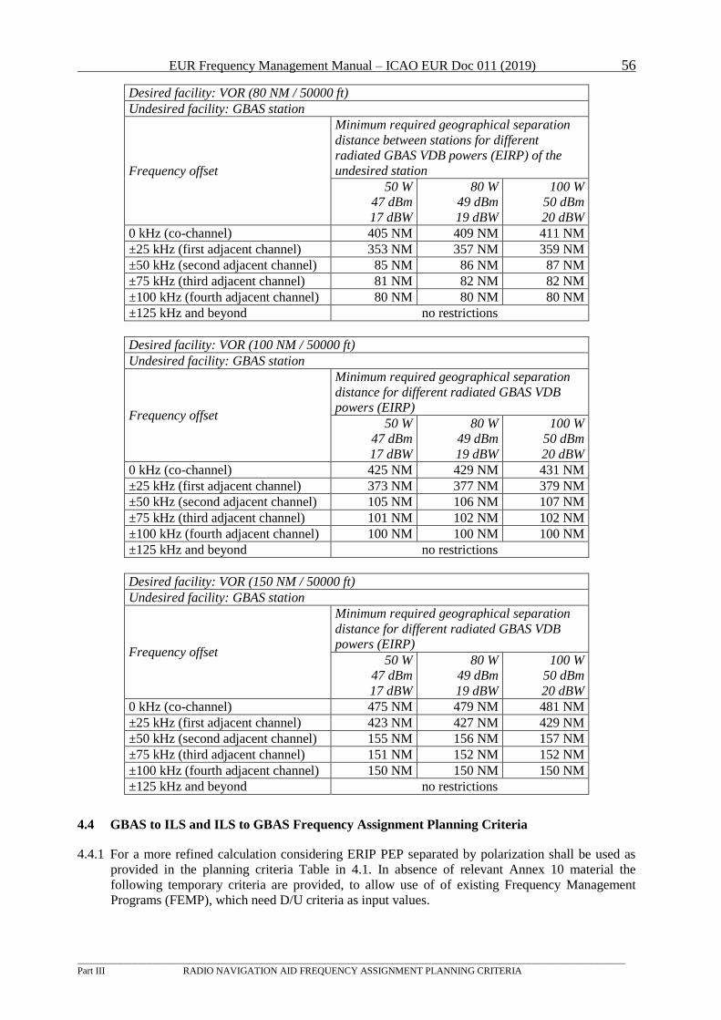
EUR Frequency Management Manual – ICAO EUR Doc 011 (2019) 56
_________________________________________________________________________________________________________________
Part III RADIO NAVIGATION AID FREQUENCY ASSIGNMENT PLANNING CRITERIA
Desired facility: VOR (80 NM / 50000 ft)
Undesired facility: GBAS station
Frequency offset
Minimum required geographical separation
distance between stations for different
radiated GBAS VDB powers (EIRP) of the
undesired station
50 W
47 dBm
17 dBW
80 W
49 dBm
19 dBW
100 W
50 dBm
20 dBW
0 kHz (co-channel) 405 NM 409 NM 411 NM
±25 kHz (first adjacent channel) 353 NM 357 NM 359 NM
±50 kHz (second adjacent channel) 85 NM 86 NM 87 NM
±75 kHz (third adjacent channel) 81 NM 82 NM 82 NM
±100 kHz (fourth adjacent channel) 80 NM 80 NM 80 NM
±125 kHz and beyond no restrictions
Desired facility: VOR (100 NM / 50000 ft)
Undesired facility: GBAS station
Frequency offset
Minimum required geographical separation
distance for different radiated GBAS VDB
powers (EIRP)
50 W
47 dBm
17 dBW
80 W
49 dBm
19 dBW
100 W
50 dBm
20 dBW
0 kHz (co-channel) 425 NM 429 NM 431 NM
±25 kHz (first adjacent channel) 373 NM 377 NM 379 NM
±50 kHz (second adjacent channel) 105 NM 106 NM 107 NM
±75 kHz (third adjacent channel) 101 NM 102 NM 102 NM
±100 kHz (fourth adjacent channel) 100 NM 100 NM 100 NM
±125 kHz and beyond no restrictions
Desired facility: VOR (150 NM / 50000 ft)
Undesired facility: GBAS station
Frequency offset
Minimum required geographical separation
distance for different radiated GBAS VDB
powers (EIRP)
50 W
47 dBm
17 dBW
80 W
49 dBm
19 dBW
100 W
50 dBm
20 dBW
0 kHz (co-channel) 475 NM 479 NM 481 NM
±25 kHz (first adjacent channel) 423 NM 427 NM 429 NM
±50 kHz (second adjacent channel) 155 NM 156 NM 157 NM
±75 kHz (third adjacent channel) 151 NM 152 NM 152 NM
±100 kHz (fourth adjacent channel) 150 NM 150 NM 150 NM
±125 kHz and beyond no restrictions
4.4 GBAS to ILS and ILS to GBAS Frequency Assignment Planning Criteria
4.4.1 For a more refined calculation considering ERIP PEP separated by polarization shall be used as
provided in the planning criteria Table in 4.1. In absence of relevant Annex 10 material the
following temporary criteria are provided, to allow use of of existing Frequency Management
Programs (FEMP), which need D/U criteria as input values.
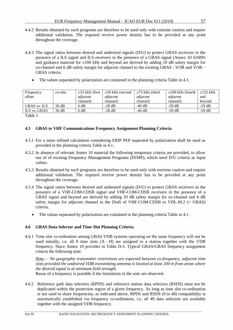
EUR Frequency Management Manual – ICAO EUR Doc 011 (2019) 57
_________________________________________________________________________________________________________________
Part III RADIO NAVIGATION AID FREQUENCY ASSIGNMENT PLANNING CRITERIA
4.4.2 Results obtained by such programs are therefore to be used only with extreme caution and require
additional validation. The required receive power density has to be provided at any point
throughout the coverage.
4.4.3 The signal ratios between desired and undesired signals (D/U) to protect GBAS receivers in the
presence of a ILS signal and ILS receivers in the presence of a GBAS signal (Annex 10 SARPs
and guidance material for ±100 kHz and beyond are derived by adding 10 dB safety margin for
co-channel and 6 dB safety margin for adjacent channel to the existing GBAS - VOR and VOR –
GBAS criteria.
The values separated by polarization are contained in the planning criteria Table in 4.1.
Frequency
offset
co-chn. ±25 kHz (first
adjacent
channel)
±50 kHz (second
adjacent
channel)
±75 kHz (third
adjacent
channel)
±100 kHz (fourth
adjacent
channel)
±125 kHz
and
beyond
GBAS vs. ILS 36 dB 6 dB -28 dB -40 dB -59 dB -59 dB
ILS vs. GBAS 36 dB 6 dB -28 dB -40 dB -59 dB -59 dB
Table 1
4.5 GBAS to VHF Communications Frequency Assignment Planning Criteria
4.5.1 For a more refined calculation considering ERIP PEP separated by polarization shall be used as
provided in the planning criteria Table in 4.1.
4.5.2 In absence of relevant Annex 10 material the following temporary criteria are provided, to allow
use of of existing Frequency Management Programs (FEMP), which need D/U criteria as input
values.
4.5.3 Results obtained by such programs are therefore to be used only with extreme caution and require
additional validation. The required receive power density has to be provided at any point
throughout the coverage.
4.5.4 The signal ratios between desired and undesired signals (D/U) to protect GBAS receivers in the
presence of a VHF-COM-CDSB signal and VHF-COM-CDSB receivers in the presence of a
GBAS signal and beyond are derived by adding 10 dB safety margin for co-channel and 6 dB
safety margin for adjacent channel to the Draft of VHF-COM-CDSB to VDL-M.2 (= GBAS)
criteria.
The values separated by polarization are contained in the planning criteria Table in 4.1.
4.6 GBAS Data Selector and Time Slot Planning Criteria
4.6.1 Time slot co-ordination among GBAS VDB systems operating on the same frequency will not be
used initially, i.e. all 8 time slots (A – H) are assigned to a station together with the VDB
frequency. Since Annex 10 provides in Table D-3. Typical GBAS/GBAS frequency assignment
criteria the following note:
Note.— No geographic transmitter restrictions are expected between co-frequency, adjacent time
slots provided the undesired VDB transmitting antenna is located at least 200 m from areas where
the desired signal is at minimum field strength.
Reuse of a frequency is possible if the limitations in the note are observed.
4.6.2 Reference path data selectors (RPDS) and reference station data selectors (RSDS) must not be
duplicated within the protection region of a given frequency. As long as time slot co-ordination
is not used to share frequencies, as indicated above, RPDS and RSDS (0 to 48) compatibility is
automatically established via frequency co-ordination, i.e. all 49 data selectors are available
together with the assigned VDB frequency.
EUR Frequency Management Manual – ICAO EUR Doc 011 (2019) 58
_________________________________________________________________________________________________________________
Part III RADIO NAVIGATION AID FREQUENCY ASSIGNMENT PLANNING CRITERIA
4.7 Special Provisions
4.7.1 The provisions below apply as long as ICAO Annex 10 GBAS frequency assignment criteria have
not been completed:
frequency assignments for GBAS VDB services should only be made on a temporary basis
and may have to be revised after 31 December 2019;
frequencies should be selected from the frequency range of 112.050 – 116.400 MHz
(frequencies above 116.400 MHz may be used if the necessary calculation using the D/U
criteria from table in 4.1. have indicated sufficient protection). Local ILS and VHF COM
frequency assignments shall be taken into account aiming at a maximum protection for ILS
and VHF-COM-CDSB;
VDB signal polarization is to be taken into account for both possible polarizations
separately, but is assumed to be horizontal;
radiated peak power of the GBAS VDB signals should be as low as practicable;
GBAS VDB systems with multiple antennas which are separated more than 1 NM must be
considered individually; and
VDB time slot and data selector shall be co-ordinated.
4.7.2 Proposals for co-ordination of GBAS assignments must include at a minimum
ITU Country Code;
Location name and co-ordinates;
Frequency;
Equipment (i.e. GBAS/H or GBAS/E);
Identification;
DOC (23 NM / 10000 ft is recommended);
Peak radiated power EIRP PEP in W for horizontal polarization;
• Peak radiated power EIRP PEP in W for vertical polarization;
antenna elevation above MSL of the phase center of the antenna;
Time slot in operation.
EUR Frequency Management Manual – ICAO EUR Doc 011 (2019) 59
_________________________________________________________________________________________________________________
Part III RADIO NAVIGATION AID FREQUENCY ASSIGNMENT PLANNING CRITERIA
5 DME
5.1 General
5.1.1 The band 960 - 1215 MHz is allocated, though not exclusively, to the aeronautical radio
navigation service and used mainly by the DME system. Within this band, two segments, around
1030 MHz and 1090 MHz, are reserved for SSR. Furthermore, some military systems make use
of this band, e.g. TACAN (essentially a DME with additional pulses for bearing information) and
data/voice systems employing frequency hopping techniques. Part 960-1164 MHz of the band is
also allocated to the aeronautical mobile (route) service, for use by next generation aeronautical
communication systems.
Note: In order to support compatibility between DME/TACAN assignments and GNSS
L5/E5 aeronautical receivers, States are encouraged to apply the recommendations
contained in section D of the Supplement to EUR Doc011 when planning new
DME/TACAN assignments.
5.1.2 References to documents:
- Annex 10, Volume I, paragraphs 3.5.3.3, 3.5.5.3.4.1
(channelling, interference rejection);
- Annex 10, Volume V, paragraph 4.3
(channel groups, pairing);
- Annex 10, Attachment C to Volume I, paragraphs 7.1.7 - 7.1.10
(signal ratios, pulse coding, adjacent channels, etc.);
- European Region Air Navigation Plan (Doc 7754), Volume I, Basic ANP, Part IV,
paragraphs 42, 44
(principles and criteria);
- European Region Air Navigation Plan (Doc 7754), Volume II, FASID, Part IV, paragraph 22
(principles and criteria).
5.1.3 DME is in many cases co-located and frequency paired (Annex 10, Volume I, chapter 3, Table A)
with another facility (VOR, ILS, MLS) and normally has the same protected range. The protection
also takes into account the pulse coding and output power. Both the first and second adjacent
channels are considered.
5.1.4 Co-ordination should follow the rules for the co-located equipment; for a stand-alone DME co-
ordination should at least include States within a radius of 400 - 500 NM.
5.1.5 Information on the planning of identifications can be found in section 7 below.
5.2 Frequency Assignment Planning Criteria
Notes: For frequency planning purposes,
1) there is no difference between DME/N and DME/P.
2) TACAN facilities are treated in the same way as DME stations.
3) no criteria are defined for DME/W because it is not used in EUR Region.
5.2.1 Protection Requirements
5.2.1.1 The necessary desired to undesired (D/U) signal ratios are needed to protect the desired
transponder reply signals at the airborne receiver from the various co-frequency/adjacent-
frequency, same pulse code/different pulse code, undesired transponder reply signal
combinations that may exist.
5.2.1.2 In making an assignment, each facility must be treated as the desired source with the other
EUR Frequency Management Manual – ICAO EUR Doc 011 (2019) 60
_________________________________________________________________________________________________________________
Part III RADIO NAVIGATION AID FREQUENCY ASSIGNMENT PLANNING CRITERIA
acting as the undesired source. If both satisfy their individual D/U requirements, then the
assignment can be made.
5.2.1.3 The channelling arrangement for DME, when considering X and Y channels only, is such that
in the ground-to-air direction (transponder reply frequency) no use is made of multiplexing
techniques on the same frequency, thus avoiding the situation where different pulse codings on
the same or adjacent frequencies have to be studied when making frequency assignments.
However, when assign4ments on DME W or Z channels have to be made, these assignments
have to be checked against interference from DME X or Y channels and vice-versa.
5.2.1.4 Co-frequencyTP
1PT protection ratios (D/U)
The co-frequency protection ratios (D/U) are:
Same pulse code: 8 dB
Different pulse code: 8 dB (column A of Table C-4, Attachment C to Annex 10,
Volume I).
Geographical separation distances are based upon the required D/U ratio, taking into
consideration the EIRP of both the desired and the undesired DME and the appropriate
propagation characteristics.
5.2.1.5 Adjacent frequency protection ratios (D/U)
The following values are assumed for the adjacent-channel emissions of the transponder:
200 mW (-7 dBW) on the first adjacent frequency
2 mW (-27 dBW) on the second adjacent frequency.
The minimum required D/U ratio within the operational service volume shall be in accordance
with the values given in Table C-4, Attachment C to Annex 10, Volume I.
5.2.1.6 Designated Operational Coverage (DOC)
5.2.1.6.1 When the DME is associated with a VOR or an ILS the coverage should be at least that of the
VOR or ILS to the extent practicable.
5.2.1.6.2 When the DME is associated with an MLS, the coverage should be omnidirectional up to the
operational range of the MLS approach azimuth facility. The protected height of the DME
should be the same as for the MLS approach azimuth sector.
5.2.1.6.3 Where the designated operational range of a given DME facility is not the same throughout
360°, the angular limits of sectorization in range should be indicated in accordance with the
method described in Appendix A to Part III.
5.2.1.6.4 The DOC for a DME with directional antenna should be specified on the basis of the particular
operational requirements. The orientation of the DOC should be defined relative to the true
(i.e. with respect to the true north – not the magnetic one) radiation direction (TRD) of the
facility. When defining the DOC for a DME with directional antenna, the antenna
characteristics of the DME facility need to be taken into account in order to ensure that
throughout the DOC the available signal level will not be lower than the minimum signal level
to be protected (-89 Dbw/m²).
5.2.1.7 Calculation of EIRP
5.2.1.7.1 The EIRP (in dBW) in any particular direction α can be calculated by means of the general
formula:
TP
1PT Co-frequency and adjacent frequency are referred to the transponder reply frequency.
EUR Frequency Management Manual – ICAO EUR Doc 011 (2019) 61
_________________________________________________________________________________________________________________
Part III RADIO NAVIGATION AID FREQUENCY ASSIGNMENT PLANNING CRITERIA
EIRP(α)= EIRPmax+ GAntenna, rel (α),
where
EIRPmax = PTransmitter Output – ALine + GAntenna, max .
PTransmitter Output is the output power of the transmitter in dBW, ALine is the attenuation of the
transmission line in dB and GAntenna, max is the antenna gain in the main beam direction in dBi
(with respect to an isotropic antenna) at the given frequency. Furthermore, GAntenna, rel (α)
denotes the normalised antenna gain in dB relative to GAntenna, max, at the given vector direction
α. In the case of DME, EIRP and PTransmitter Output are meant as PEP (Peak Envelope Power)
values.
Note: GAntenna, rel is always less than or equal to 0 dB. For an omnidirectional antenna, the
normalized gain GAntenna, rel is taken equal to 0 dB.
5.2.1.7.2 The value of the foreseen EIRPmax shall be provided with the frequency co-ordination request.
It is calculated as above, where PTransmitter Output should be sufficient to produce adequate power
flux density throughout the DOC.
5.2.1.7.3 Typical EIRPmax values per category of facility are given below as guidance, based on
standard transmitter output power, feeder line losses and antenna gain:
Landing DME: 27 dBW, Omnidirectional
29 dBW, Directional
En-route DME: 37 dBW
TACAN: 40 dBW.
5.2.1.7.4 For the sake of spectrum economy, it is highly recommended that technical measures be taken
so that the EIRPmax of landing DME with directional antenna does not exceed 29 dBW,
despite the high gain provided by the beacon antenna.
5.2.2 Propagation model
5.2.2.1 Propagation characteristics
5.2.2.1.1 The same propagation conditions along the path of the desired and the undesired signals are
assumed. Within the radio line-of-sight, free space attenuation is assumed. Beyond the radio
line-of-sight, propagation is approximated by an attenuation rate of 1.6 dB/NM. This is derived
from the propagation 1200 MHz/50% time curve in Rec. ITU-R P.528-2 (former CCIR Rec.
528-1). For radio propagation and radio horizon calculations a smooth Earth is assumed with
an effective 4/3 Earth radius.
Within and beyond the radio line-of-sight situations are depicted below. Two points are
considered to be within radio line-of-sight if their separation distance is smaller than the sum
of their respective radio distances.
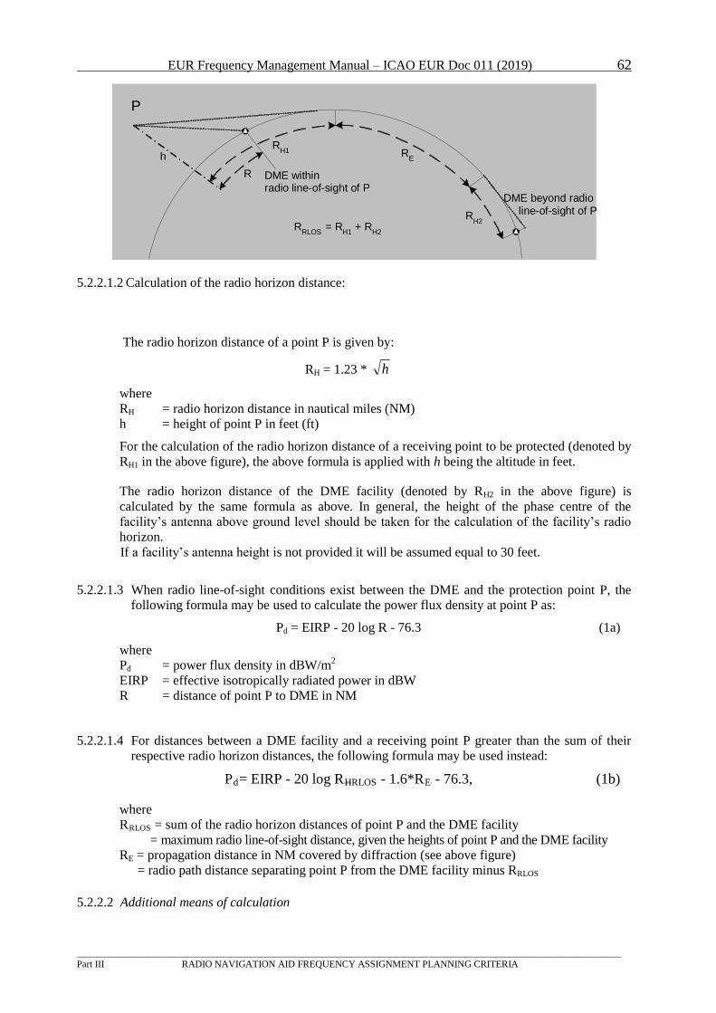
EUR Frequency Management Manual – ICAO EUR Doc 011 (2019) 62
_________________________________________________________________________________________________________________
Part III RADIO NAVIGATION AID FREQUENCY ASSIGNMENT PLANNING CRITERIA
5.2.2.1.2 Calculation of the radio horizon distance:
The radio horizon distance of a point P is given by:
RBHB = 1.23 * h
where
RBH B= radio horizon distance in nautical miles (NM)
h = height of point P in feet (ft)
For the calculation of the radio horizon distance of a receiving point to be protected (denoted by
RH1 in the above figure), the above formula is applied with h being the altitude in feet.
The radio horizon distance of the DME facility (denoted by RH2 in the above figure) is
calculated by the same formula as above. In general, the height of the phase centre of the
facility’s antenna above ground level should be taken for the calculation of the facility’s radio
horizon.
If a facility’s antenna height is not provided it will be assumed equal to 30 feet.
5.2.2.1.3 When radio line-of-sight conditions exist between the DME and the protection point P, the
following formula may be used to calculate the power flux density at point P as:
PBd B = EIRP - 20 log R - 76.3 (1a)
where
PBdB = power flux density in dBW/mP
2P
EIRP = effective isotropically radiated power in dBW
R = distance of point P to DME in NM
5.2.2.1.4 For distances between a DME facility and a receiving point P greater than the sum of their
respective radio horizon distances, the following formula may be used instead:
PBd = EIRP - 20 log RBHRLOSB - 1.6*RBEB - 76.3, (1b)
where
RBRLOSB = sum of the radio horizon distances of point P and the DME facility
= maximum radio line-of-sight distance, given the heights of point P and the DME facility
RE = propagation distance in NM covered by diffraction (see above figure)
= radio path distance separating point P from the DME facility minus RRLOS
5.2.2.2 Additional means of calculation
R E
R H2
h
P
R RLOS = R
H1 + R H2
R H1
R
DME beyond radio line-of-sight of P
DME within radio line-of-sight of P
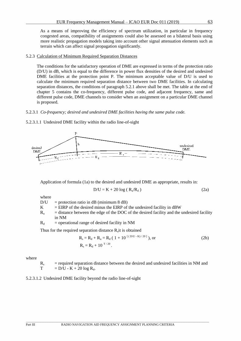
EUR Frequency Management Manual – ICAO EUR Doc 011 (2019) 63
_________________________________________________________________________________________________________________
Part III RADIO NAVIGATION AID FREQUENCY ASSIGNMENT PLANNING CRITERIA
As a means of improving the efficiency of spectrum utilization, in particular in frequency
congested areas, compatibility of assignments could also be assessed on a bilateral basis using
more realistic propagation models taking into account other signal attenuation elements such as
terrain which can affect signal propagation significantly.
5.2.3 Calculation of Minimum Required Separation Distances
The conditions for the satisfactory operation of DME are expressed in terms of the protection ratio
(D/U) in dB, which is equal to the difference in power flux densities of the desired and undesired
DME facilities at the protection point P. The minimum acceptable value of D/U is used to
calculate the minimum required separation distance between two DME facilities. In calculating
separation distances, the conditions of paragraph 5.2.1 above shall be met. The table at the end of
chapter 5 contains the co-frequency, different pulse code, and adjacent frequency, same and
different pulse code, DME channels to consider when an assignment on a particular DME channel
is proposed.
5.2.3.1 Co-frequency; desired and undesired DME facilities having the same pulse code.
5.2.3.1.1 Undesired DME facility within the radio line-of-sight
Application of formula (1a) to the desired and undesired DME as appropriate, results in:
D/U = K + 20 log ( RBuB/RBdB ) (2a)
where
D/U = protection ratio in dB (minimum 8 dB)
K = EIRP of the desired minus the EIRP of the undesired facility in dBW
RBuB = distance between the edge of the DOC of the desired facility and the undesired facility
in NM
RBdB = operational range of desired facility in NM
Thus for the required separation distance R BsBit is obtained
RBs B = Rd + Ru = RBdB ( 1 + 10 P
[ ( D/U - K) / 20 ]P ), or (2b)
Rs = Rd + 10 T / 20
.
where
RBs B = required separation distance between the desired and undesired facilities in NM and
T = D/U - K + 20 log Rd.
5.2.3.1.2 Undesired DME facility beyond the radio line-of-sight
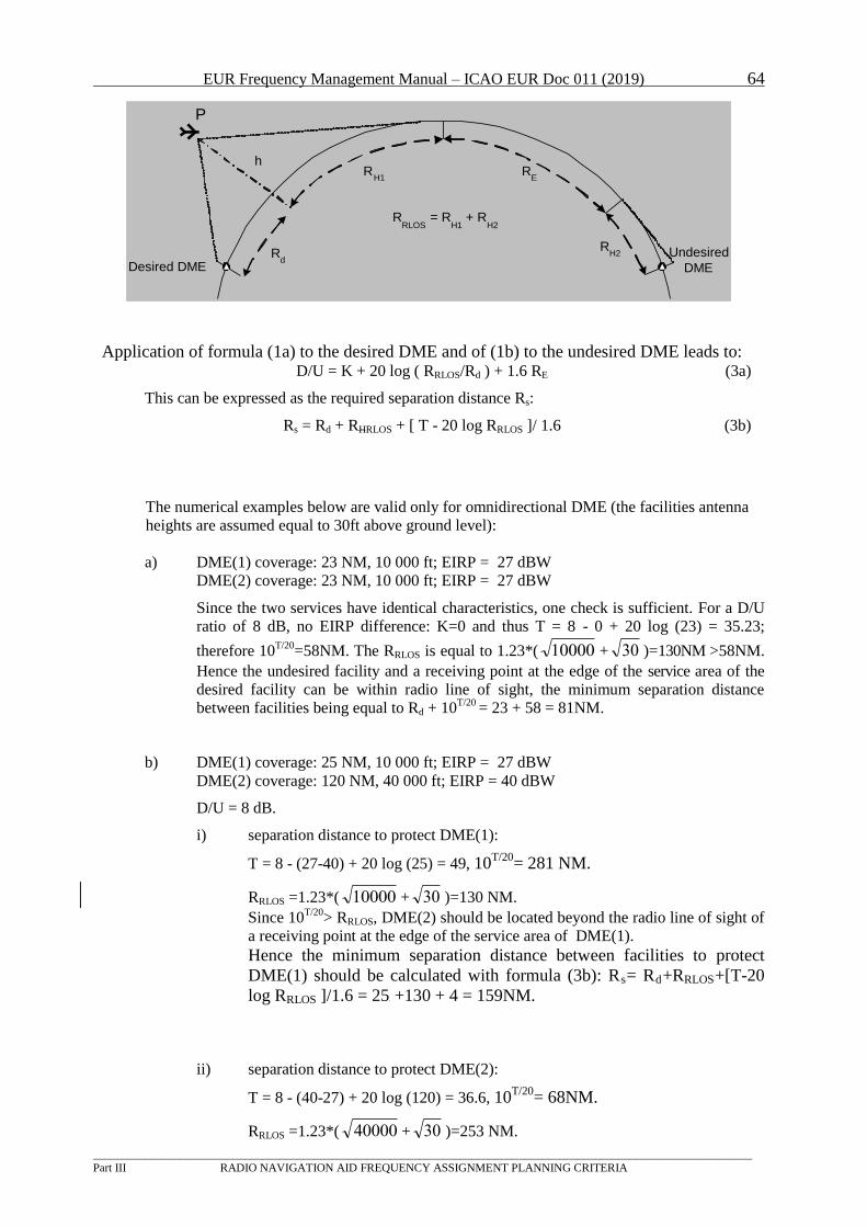
EUR Frequency Management Manual – ICAO EUR Doc 011 (2019) 64
_________________________________________________________________________________________________________________
Part III RADIO NAVIGATION AID FREQUENCY ASSIGNMENT PLANNING CRITERIA
R E
R H2
Desired DME Undesired
DME
h
P
R RLOS = R
H1 + R H2
R H1
R d
Application of formula (1a) to the desired DME and of (1b) to the undesired DME leads to: D/U = K + 20 log ( RRLOSB/RBdB ) + 1.6 RBEB (3a)
This can be expressed as the required separation distance RBs B:
RBs B = RBdB + RBHRLOSB + [ T - 20 log RRLOS ]/ 1.6 (3b)
The numerical examples below are valid only for omnidirectional DME (the facilities antenna
heights are assumed equal to 30ft above ground level):
a) DME(1) coverage: 23 NM, 10 000 ft; EIRP = 27 dBW
DME(2) coverage: 23 NM, 10 000 ft; EIRP = 27 dBW
Since the two services have identical characteristics, one check is sufficient. For a D/U
ratio of 8 dB, no EIRP difference: K=0 and thus T = 8 - 0 + 20 log (23) = 35.23;
therefore 10T/20
=58NM. The RRLOS is equal to 1.23*( 10000 + 30 )=130NM >58NM.
Hence the undesired facility and a receiving point at the edge of the service area of the
desired facility can be within radio line of sight, the minimum separation distance
between facilities being equal to RBdB + 10T/20
= 23 + 58 = 81NM.
b) DME(1) coverage: 25 NM, 10 000 ft; EIRP = 27 dBW
DME(2) coverage: 120 NM, 40 000 ft; EIRP = 40 dBW
D/U = 8 dB.
i) separation distance to protect DME(1):
T = 8 - (27-40) + 20 log (25) = 49, 10T/20
= 281 NM.
RRLOS =1.23*( 10000 + 30 )=130 NM.
Since 10T/20
> RRLOS, DME(2) should be located beyond the radio line of sight of
a receiving point at the edge of the service area of DME(1).
Hence the minimum separation distance between facilities to protect
DME(1) should be calculated with formula (3b): R BsB= RBdB+RRLOSB+[T-20
log RRLOS ]/1.6 = 25B +130 + 4 = 159NM.
ii) separation distance to protect DME(2):
T = 8 - (40-27) + 20 log (120) = 36.6, 10T/20
= 68NM.
RRLOS =1.23*( 40000 + 30 )=253 NM.
EUR Frequency Management Manual – ICAO EUR Doc 011 (2019) 65
_________________________________________________________________________________________________________________
Part III RADIO NAVIGATION AID FREQUENCY ASSIGNMENT PLANNING CRITERIA
Now 10T/20
<RRLOS, with the result that DME(1) can be within radio line of sight
of a receiving point at the edge of the service area of DME(2), the minimum
separation distance between facilities to protect DME(2) being equal to RBsB= RBd B
+ 10T/20
= 120 + 68 = 188 NM.
To assure protection to both facilities, the required separation distance between these facilities
should be at least 188 NM.
5.2.3.2 Co-frequency; desired and undesired DME facility having different pulse codes
Since the required protection is provided at the airborne DME receiver, different pulse coding
protection is only required when a DME X channel is interfered with a DME W channel (or
DME Y versus DME Z) or vice versa (see also paragraph 5.2.1.3). The separation distances can
be calculated along the same principles as indicated in paragraph 5.2.3.1. The protection ratio is
8 dB (see paragraph. 5.2.1.4).
5.2.3.3 Adjacent channel separation distances
5.2.3.3.1 First adjacent frequency
The minimum separation distance between DMEs operating on first-adjacent channels shall be
65 NM between beacons or 5NM from the DOC-edge of the desired beacon, whichever gives
the lesser distance between beacons.
Notes:
1 The above criteria ensure that the D/U ratio within the operational service volume does not fall
below the values given in Table C-4, Attachment C to Annex 10, Volume I.
2. Since calculations for a DME/P show that all separation distances derived for the Initial
Approach (IA) mode (-89 dBW/mP
2P at 23 NM) are larger than for the Final Approach (FA) mode
(-75 dBW/mP
2P at 7 NM), it is sufficient to consider only the IA mode protection.
5.2.3.3.2 Second adjacent frequency
The second adjacent frequency separation distances are almost insignificant. However it is
recommended that second adjacent frequency assignments on the same aerodrome should be
avoided. For practical planning purposes, a minimum required separation distance between
the facilities of 10 NM may be used.
5.2.3.4 Separation requirement for DME frequencies which are separated by 63 MHz
Annex 10, Attachment C to Volume I, paragraph 7.1.9 indicates that "assignment of an Y or Z
channel whose reply frequency is 63 MHz from the reply frequency of another channel (either
W, X, Y, Z) or vice versa requires a separation distance of at least 28 km (15 NM) between
facilities" (Annex 10, Attachment C to Volume I, paragraph 3.4.9 gives a less conservative
minimum separation distance of 10 NM).
This requirement is to prevent desensitization that may occur to the transponder that is receiving
on the same frequency the other transponder is transmitting, irrespective of the pulse code.
For example:
downlink uplink downlink uplink
18X(W) 1042 979 81X(W) U1105U 1168
EUR Frequency Management Manual – ICAO EUR Doc 011 (2019) 66
_________________________________________________________________________________________________________________
Part III RADIO NAVIGATION AID FREQUENCY ASSIGNMENT PLANNING CRITERIA
18Y(Z) 1042 U1105U 81Y(Z) U1105U 1042
Channel 18Y(Z), transmitting on 1105 MHz may cause interference to the transponder receiver
operating on channels 81X(W) or 81Y(Z). Similarly, channel 81Y(Z) may interfere with
channels 18X(W) and 18Y(Z).
5.2.3.5 Sectorization
The material of paragraph 3.3.5 (VOR) on sectorization is also applicable for DME. However,
the calculation of the separations distance must be adapted as indicated below:
The correct assessment of compatibility for facility A requires the following calculations:
Co-channel:
Minimum separation distance between “Critical Point” and transmitter B:
RBs B = RBdB*10P[(D/U– K)/20]P if undesired facility within radio line-of-sight;
or
RBs B = RBHB+[D/U-K-20 log (R BHB/RBd B)]/1.6 if undesired facility beyond radio line-of-sight;
(this is derived from a subtraction of Rd from R Bs B = RBdB (1 + 10[(D/U-K)/20]
) and from
RBdB+RBHB+[D/U-K-20 log (R BHB/RBdB)]/1.6.);
where
RBdB = operational range of facility A at the “ Critical Point”.
Co-frequency:
Minimum separation distance between “ Critical Point” and transmitter B:
RBs B = RBdB*10[(D/U-K)/20]
if undesired facility within radio line-of-sight; or
RBs B = RBHB+[D/U-K-20 log (RBHB/RBd B)]/1.6 if undesired facility beyond radio line-of-sight;
(this is derived from a subtraction of Rd from R Bs B = RBdB (1 + 10[(D/U-K)/20]
) and from
RBdB+RBHB+[D/U-K-20 log (R BHB/RBdB)]/1.6.).
First adjacent channel for DMEs with a DOC radius of 60 NM or less:
Minimum separation distance between “ Critical Point” and transmitter B:
Range of facility A plus 5 NM.
First adjacent channel for DMEs with a DOC radius of greater than 60 NM:
Minimum 65 NM separation distance between facilities A and B.
Second adjacent channel:
Minimum separation distance between transmitter A and transmitter B:
10 NM.
63 MHz separated facilities:
Minimum separation distance between transmitter A and transmitter B:
15 NM.
Compatibility of facility A (undesired facility) with B (desired facility) must also be considered.
If the “ Critical Point” lies on the direct line between the two facilities A and B, then the
“normal” calculation method may be applied (i.e. point “P” is “ Critical Point”).
5.2.3.6 Use of DMEs with directional antennas
When omnidirectional coverage is not required, the use of a DME with directional antenna is
encouraged, subject to the proviso that the operational requirements for the service to be
provided by this facility are met. In Particular, they are useful for the replacement of ILS marker
beacons. The directional DME could provide a means to mitigate frequency congestion.
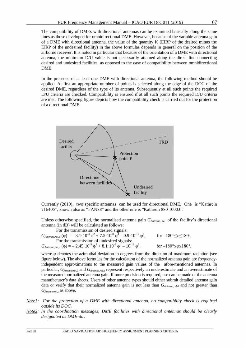
EUR Frequency Management Manual – ICAO EUR Doc 011 (2019) 67
_________________________________________________________________________________________________________________
Part III RADIO NAVIGATION AID FREQUENCY ASSIGNMENT PLANNING CRITERIA
Undesired
facility
Protection
point P
TRD Desired
facility
Direct line
between facilities
The compatibility of DMEs with directional antennas can be examined basically along the same
lines as those developed for omnidirectional DME. However, because of the variable antenna gain
of a DME with directional antenna, the value of the quantity K (EIRP of the desired minus the
EIRP of the undesired facility) in the above formulas depends in general on the position of the
airborne receiver. It is noted in particular that because of the orientation of a DME with directional
antenna, the minimum D/U value is not necessarily attained along the direct line connecting
desired and undesired facilities, as opposed to the case of compatibility between omnidirectional
DME.
In the presence of at least one DME with directional antenna, the following method should be
applied. At first an appropriate number of points is selected along the edge of the DOC of the
desired DME, regardless of the type of its antenna. Subsequently at all such points the required
D/U criteria are checked. Compatibility is ensured if at all such points the required D/U criteria
are met. The following figure depicts how the compatibility check is carried out for the protection
of a directional DME.
Currently (2010), two specific antennas can be used for directional DME. One is “Kathrein
716405”, known also as “FAN88” and the other one is “Kathrein 880 10003”.
Unless otherwise specified, the normalised antenna gain GAntenna, rel of the facility’s directional
antenna (in dB) will be calculated as follows:
For the transmission of desired signals:
GAntenna,rel,d (φ) = – 3.1·10-3
φ2 + 7.5·10
-8 φ
4 – 0.9·10
-12 φ
6, for –180°≤φ≤180°.
For the transmission of undesired signals:
GAntenna,rel,u (φ) = – 2.45·10-3
φ2 + 8.1·10
-8 φ
4 – 10
-12 φ
6, for –180°≤φ≤180°,
where φ denotes the azimuthal deviation in degrees from the direction of maximum radiation (see
figure below). The above formulas for the calculation of the normalized antenna gain are frequency-
independent approximations to the measured gain values of the afore-mentioned antennas. In
particular, GAntenna,rel,d and GAntenna,rel,u represent respectively an underestimate and an overestimate of
the measured normalized antenna gain. If more precision is required, use can be made of the antenna
manufacturer’s data sheets. Users of other antenna types should either submit detailed antenna gain
data or verify that their normalized antenna gain is not less than GAntenna,rel,d and not greater than
GAntenna,rel,u as above.
Note1: For the protection of a DME with directional antenna, no compatibility check is required
outside its DOC.
Note2: In the coordination messages, DME facilities with directional antennas should be clearly
designated as DME-dir.
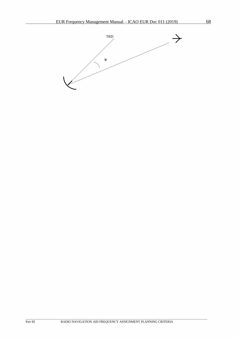
EUR Frequency Management Manual – ICAO EUR Doc 011 (2019) 68
_________________________________________________________________________________________________________________
Part III RADIO NAVIGATION AID FREQUENCY ASSIGNMENT PLANNING CRITERIA
TRD
φ
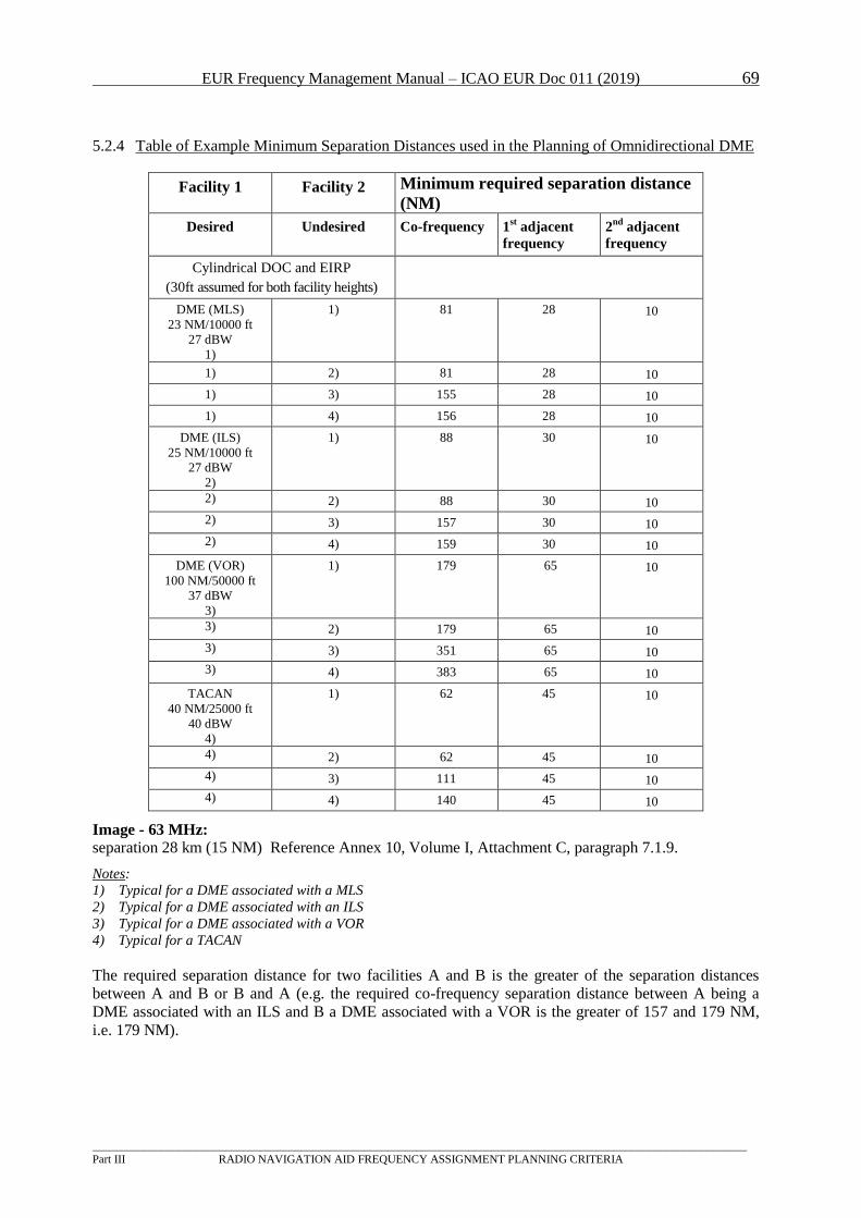
EUR Frequency Management Manual – ICAO EUR Doc 011 (2019) 69
_________________________________________________________________________________________________________________
Part III RADIO NAVIGATION AID FREQUENCY ASSIGNMENT PLANNING CRITERIA
5.2.4 Table of Example Minimum Separation Distances used in the Planning of Omnidirectional DME
Facility 1 Facility 2 Minimum required separation distance
(NM)
Desired Undesired Co-frequency 1 P
stP adjacent
frequency
2 P
ndP adjacent
frequency
Cylindrical DOC and EIRP
(30ft assumed for both facility heights)
DME (MLS)
23 NM/10000 ft
27 dBW
1)
1) 81 28 10
1) 2) 81 28 10
1) 3) 155 28 10
1) 4) 156 28 10
DME (ILS)
25 NM/10000 ft
27 dBW
2)
1) 88 30 10
2) 2) 88 30 10
2) 3) 157 30 10
2) 4) 159 30 10
DME (VOR)
100 NM/50000 ft
37 dBW
3)
1) 179 65 10
3) 2) 179 65 10
3) 3) 351 65 10
3) 4) 383 65 10
TACAN
40 NM/25000 ft
40 dBW
4)
1) 62 45 10
4) 2) 62 45 10
4) 3) 111 45 10
4) 4) 140 45 10
Image - 63 MHz:
separation 28 km (15 NM) Reference Annex 10, Volume I, Attachment C, paragraph 7.1.9.
Notes:
1) Typical for a DME associated with a MLS
2) Typical for a DME associated with an ILS
3) Typical for a DME associated with a VOR
4) Typical for a TACAN
The required separation distance for two facilities A and B is the greater of the separation distances
between A and B or B and A (e.g. the required co-frequency separation distance between A being a
DME associated with an ILS and B a DME associated with a VOR is the greater of 157 and 179 NM,
i.e. 179 NM).
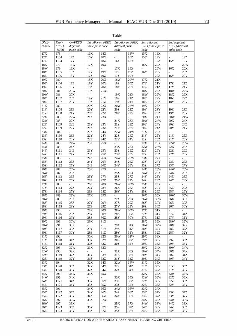
EUR Frequency Management Manual – ICAO EUR Doc 011 (2019) 70
_________________________________________________________________________________________________________________
Part III RADIO NAVIGATION AID FREQUENCY ASSIGNMENT PLANNING CRITERIA
Table
DME-channel
Reply FREQ
(MHz)
Co-FREQ different
pulse code
1st adjacent FREQ same pulse code
1st adjacent FREQ different pulse
code
2nd adjacent FREQ same pulse
code
2nd adjacent FREQ different
pulse code
17X
17Y 17Z
978
1104 1104
-
17Z 17Y
16X
16Y -
18X
18Y 18Z
-
- 16Y
18W
18Z 18Y
15X
15Y -
19X
19Y 19Z
-
- 15Y
-
19Z 19Y
18X
18W 18Y
18Z
979
979 1105
1105
18W
18X 18Z
18Y
17X
- 17Y
17Z
19X
- 19Y
19Z
-
17X 17Z
17Y
-
19X 19Z
19Y
16X
- 16Y
-
20X
20W 20Y
20Z
-
16X -
16Y
20W
20X 20Z
20Y
19X
19Y 19Z
980
1106 1106
-
19Z 19Y
18X
18Y 18Z
20X
20Y 20Z
18W
18Z 18Y
20W
20Z 20Y
17X
17Y 17Z
21X
21Y 21Z
-
17Z 17Y
-
21Z 21Y
20X
20W 20Y
20Z
981
981 1107
1107
20W
20X 20Z
20Y
19X
- 19Y
19Z
21X
- 21Y
21Z
-
19X 19Z
19Y
-
21X 21Z
21Y
18X
18W 18Y
18Z
22X
22W 22Y
22Z
18W
18X 18Z
18Y
22W
22X 22Z
22Y
21X
21Y
21Z
982
1108
1108
-
21Z
21Y
20X
20Y
20Z
22X
22Y
22Z
20W
20Z
20Y
22W
22Z
22Y
19X
19Y
19Z
23X
23Y
23Z
-
19Z
19Y
-
23Z
23Y
22X
22W 22Y
22Z
983
983 1109
1109
22W
22X 22Z
22Y
21X
- 21Y
21Z
23X
- 23Y
23Z
-
21X 21Z
21Y
-
23X 23Z
23Y
20X
20W 20Y
20Z
24X
24W 24Y
24Z
20W
20X 20Z
20Y
24W
24X 24Z
24Y
23X 23Y
23Z
984 1110
1110
- 23Z
23Y
22X 22Y
22Z
24X 24Y
24Z
22W 22Z
22Y
24W 24Z
24Y
21X 21Y
21Z
25X 25Y
25Z
- 21Z
21Y
- 25Z
25Y
24X
24W 24Y
24Z
985
985 1111
1111
24W
24X 24Z
24Y
23X
- 23Y
23Z
25X
- 25Y
25Z
-
23X 23Z
23Y
-
25X 25Z
25Y
22X
22W 22Y
22Z
26X
26W 26Y
26Z
22W
22X 22Z
22Y
26W
26X 26Z
26Y
25X 25Y
25Z
986 1112
1112
- 25Z
25Y
24X 24Y
24Z
26X 26Y
26Z
24W 24Z
24Y
26W 26Z
26Y
23X 23Y
23Z
27X 27Y
27Z
- 23Z
23Y
- 27Z
27Y
26X
26W 26Y
26Z
987
987 1113
1113
26W
26X 26Z
26Y
25X
- 25Y
25Z
27X
- 27Y
27Z
-
25X 25Z
25Y
-
27X 27Z
27Y
24X
24W 24Y
24Z
28W
28X 28Y
28Z
24W
24X 24Z
24Y
28W
28X 28Z
28Y
27X
27Y
27Z
988
1114
1114
-
27Z
27Y
26X
26Y
26Z
28X
28Y
28Z
26W
26Z
26Y
28W
28Z
28Y
25X
25Y
25Z
29X
29Y
29Z
-
25Z
25Y
-
29Z
29Y
28X
28W 28Y
28Z
989
989 1115
1115
28W
28X 28Z
28Y
27X
- 27Y
27Z
29X
- 29Y
29Z
-
27X 27Z
27Y
-
29X 29Z
29Y
26X
26W 26Y
26Z
30X
30W 30Y
30Z
26W
26X 26Z
26Y
30W
30X 30Z
30Y
29X 29Y
29Z
990 1116
1116
- 29Z
29Y
28X 28Y
28Z
30X 30Y
30Z
28W 28Z
28Y
30W 30Z
30Y
27X 27Y
27Z
31X 31Y
31Z
- 27Z
27Y
- 31Z
31Y
30X 30W
30Y
30Z
991 991
1117
1117
30W 30X
30Z
30Y
29X -
29Y
29Z
31X -
31Y
31Z
- 29X
29Z
29Y
- 31X
31Z
31Y
28X 28W
28Y
28Z
32X 32W
32Y
32Z
28W 28X
28Z
28Y
32W 32X
32Z
32Y
31X 31Y
31Z
992 1118
1118
- 31Z
31Y
30X 30Y
30Z
32X 32Y
32Z
30W 30Z
30Y
32W 32Z
32Y
29X 29Y
29Z
33X 33Y
33Z
- 29Z
29Y
- 33Z
33Y
32X 32W
32Y
32Z
993 993
1119
1119
32W 32X
32Z
32Y
31X -
31Y
31Z
33X -
33Y
33Z
- 31X
31Z
31Y
- 33X
33Y
33Z
30X 30W
30Y
30Z
34X 34W
34Y
34Z
30W 30X
30Z
30Y
34W 34X
34Z
34Y
33X 33Y
33Z
994 1120
1120
- 33Z
33Y
32X 32Y
32Z
34X 34Y
34Z
32W 32Z
32Y
34W 34Z
34Y
31X 31Y
31Z
35X 35Y
35Z
- 31Z
31Y
- 35Z
35Y
34X 34W
34Y
34Z
995 995
1121
1121
34W 34X
34Z
34Y
33X -
33Y
33Z
35X -
35Y
35Z
- 33X
33Z
33Y
- 35X
35Z
35Y
32X 32W
32Y
32Z
36X 36W
36Y
36Z
32W 32X
32Z
32Y
36W 36X
36Z
36Y
35X 35Y
35Z
996 1122
1122
- 35Z
35Y
34X 34Y
34Z
36X 36Y
36Z
34W 34Z
34Y
36W 36Z
36Y
33X 33Y
33Z
37X 37Y
37Z
- 33Z
33Y
- 37Z
37Y
36X 36W
36Y
36Z
997 997
1123
1123
36W 36X
36Z
36Y
35X -
35Y
35Z
37X -
37Y
37Z
- 35X
35Z
35Y
- 37X
37Z
37Y
34X 34W
34Y
34Z
38X 38W
38Y
38Z
34W 34X
34Z
34Y
38W 38X
38Z
38Y
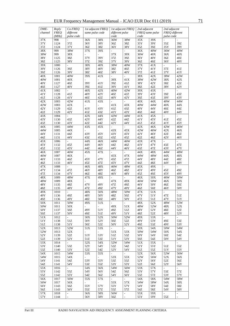
EUR Frequency Management Manual – ICAO EUR Doc 011 (2019) 71
_________________________________________________________________________________________________________________
Part III RADIO NAVIGATION AID FREQUENCY ASSIGNMENT PLANNING CRITERIA
DME-
channel
Reply
FREQ (MHz)
Co-FREQ
different pulse code
1st adjacent FREQ
same pulse code
1st adjacent FREQ
different pulse code
2nd adjacent
FREQ same pulse code
2nd adjacent
FREQ different pulse code
37X 37Y 37Z
998 1124 1124
- 37Z 37Y
36X 36Y 36Z
38X 38Y 38Z
36W 36Z 36Y
38W 38Z 38Y
35X 35Y 35Z
39X 39Y 39Z
- 35Z 35Y
- 39Z 39Y
38X 38W
38Y 38Z
999 999
1125 1125
38W 38X
38Z 38Y
37X -
37Y 37Z
39X -
39Y 39Z
- 37X
37Z 37Y
- 39X
39Z 39Y
36X 36W
36Y 36Z
40W 40X
40Y 40Z
36W 36X
36Z 36Y
40W 40X
40Z 40Y
39X 39Y 39Z
1000 1126 1126
- 39Z 39Y
38X 38Y 38Z
40X 40Y 40Z
38W 38Z 38Y
40W 40Z 40Y
37X 37Y 37Z
41X 41Y 41Z
- 37Z 37Y
- 41Z 41Y
40X 40W
40Y 40Z
1001 1001
1127 1127
40W 40X
40Z 40Y
39X -
39Y 39Z
41X -
41Y 41Z
- 39X
39Z 39Y
- 41X
41Z 41Y
38X 38W
38Y 38Z
42X 42W
42Y 42Z
38W 38X
38Z 38Y
42W 42X
42Z 42Y
41X 41Y 41Z
1002 1128 1128
- 41Z 41Y
40X 40Y 40Z
42X 42Y 42Z
40W 40Z 40Y
42W 42Z 42Y
39X 39Y 39Z
43X 43Y 43Z
- 39Z 39Y
- 43Z 43Y
42X
42W
42Y 42Z
1003
1003
1129 1129
42W
42X
42Z 42Y
41X
-
41Y 41Z
43X
-
43Y 43Z
-
41X
41Z 41Y
-
43X
43Z 43Y
40X
40W
40Y 40Z
44X
44W
44Y 44Z
40W
40X
40Z 40Y
44W
44X
44Z 44Y
43X
43Y 43Z
1004
1130 1130
-
43Z 43Y
42X
42Y 42Z
44X
44Y 44Z
42W
42Z 42Y
44W
44Z 44Y
41X
41Y 41Z
45X
45Y 45Z
-
41Z 41Y
-
45Z 45Y
44X
44W 44Y
44Z
1005
1005 1131
1131
44W
44X 44Z
44Y
43X
- 43Y
43Z
45X
- 45Y
45Z
-
43X 43Y
43Z
-
45X 45Y
45Z
42X
42W 42Y
42Z
46X
46W 46Y
46Z
42W
42X 42Z
42Y
46W
46X 46Z
46Y
45X
45Y 45Z
1006
1132 1132
-
45Z 45Y
44X
44Y 44Z
46X
46Y 46Z
44W
44Z 44Y
46W
46Z 46Y
43X
43Y 43Z
47X
47Y 47Z
-
43Z 43Y
-
47Z 47Y
46X
46W 46Y
46Z
1007
1007 1133
1133
46W
46X 46Z
46Y
45X
- 45Y
45Z
47X
- 47Y
47Z
-
45X 45Z
45Y
-
47X 47Z
47Y
44X
44W 44Y
44Z
48X
48W 48Y
48Z
44W
44X 44Z
44Y
48W
48X 48Z
48Y
47X
47Y 47Z
1008
1134 1134
-
47Z 47Y
46X
46Y 46Z
48X
48Y 48Z
46W
46Z 46Y
48W
48Z 48Y
45X
45Y 45Z
49X
49Y 49Z
-
45Z 45Y
-
49Z 49Y
48X
48W
48Y
48Z
1009
1009
1135
1135
48W
48X
48Z
48Y
47X
-
47Y
47Z
49X
-
49Y
49Z
-
47X
47Z
47Y
-
49X
49Z
49Y
46X
46W
46Y
46Z
50X
50W
50Y
50Z
46W
46X
46Z
46Y
50W
50X
50Z
50Y
49X
49Y 49Z
1010
1136 1136
-
49Z 49Y
48X
48Y 48Z
50X
50Y 50Z
48W
48Z 48Y
50W
50Z 50Y
47X
47Y 47Z
51X
51Y 51Z
-
47Z 47Y
-
51Z 51Y
50X
50W 50Y
50Z
1011
1011 1137
1137
50W
50X 50Z
50Y
49X
- 49Y
49Z
51X
- 51Y
51Z
-
49X 49Z
49Y
-
51X 51Z
51Y
48X
48W 48Y
48Z
52X
52W 52Y
52Z
48W
48X 48Z
48Y
52W
52X 52Z
52Y
51X 51Y
51Z
1012 1138
1138
- 51Z
51Y
50X 50Y
50Z
52X 52Y
52Z
50W 50Z
50Y
52W 52Z
52Y
49X 49Y
49Z
53X 53Y
53Z
- 49Z
49Y
- 53Z
53Y
52X
52W 52Y
52Z
1013
1013 1139
1139
52W
52X 52Z
52Y
51X
- 51Y
51Z
53X
- 53Y
53Z
-
51X 51Z
51Y
-
53X 53Z
53Y
50X
50W 50Y
50Z
54X
54W 54Y
54Z
50W
50X 50Z
50Y
54W
54X 54Z
54Y
53X 53Y
53Z
1014 1140
1140
- 53Z
53Y
52X 52Y
52Z
54X 54Y
54Z
52W 52Z
52Y
54W 54Z
54Y
51X 51Y
51Z
55X 55Y
55Z
- 51Z
51Y
- 55Z
55Y
54X
54W 54Y
54Z
1015
1015 1141
1141
54W
54X 54Z
54Y
53X
- 53Y
53Z
55X
- 55Y
55Z
-
53X 53Z
53Y
-
55X 55Z
55Y
52X
52W 52Y
52Z
56X
56W 56Y
56Z
52W
52X 52Z
52Y
56W
56X 56Z
56Y
55X 55Y
55Z
1016 1142
1142
- 55Z
55Y
54X 54Y
54Z
56X 56Y
56Z
54W 54Z
54Y
56W 56Z
56Y
53X 53Y
53Z
57X 57Y
57Z
- 53Z
53Y
- 57Z
57Y
56X
56W 56Y
56Z
1017
1017 1143
1143
56W
56X 56Z
56Y
55X
- 55Y
55Z
57X
- 57Y
57Z
-
55X 55Y
55Z
-
57X 57Y
57Z
54X
54W 54Y
54Z
58X
58W 58Y
58Z
54W
54X 54Z
54Y
58W
58X 58Z
58Y
57X 57Y
1018 1144
- -
56X 56Y
58X 58Y
56W 56Z
- -
55X 55Y
59X 59Y
- 55Z
- -
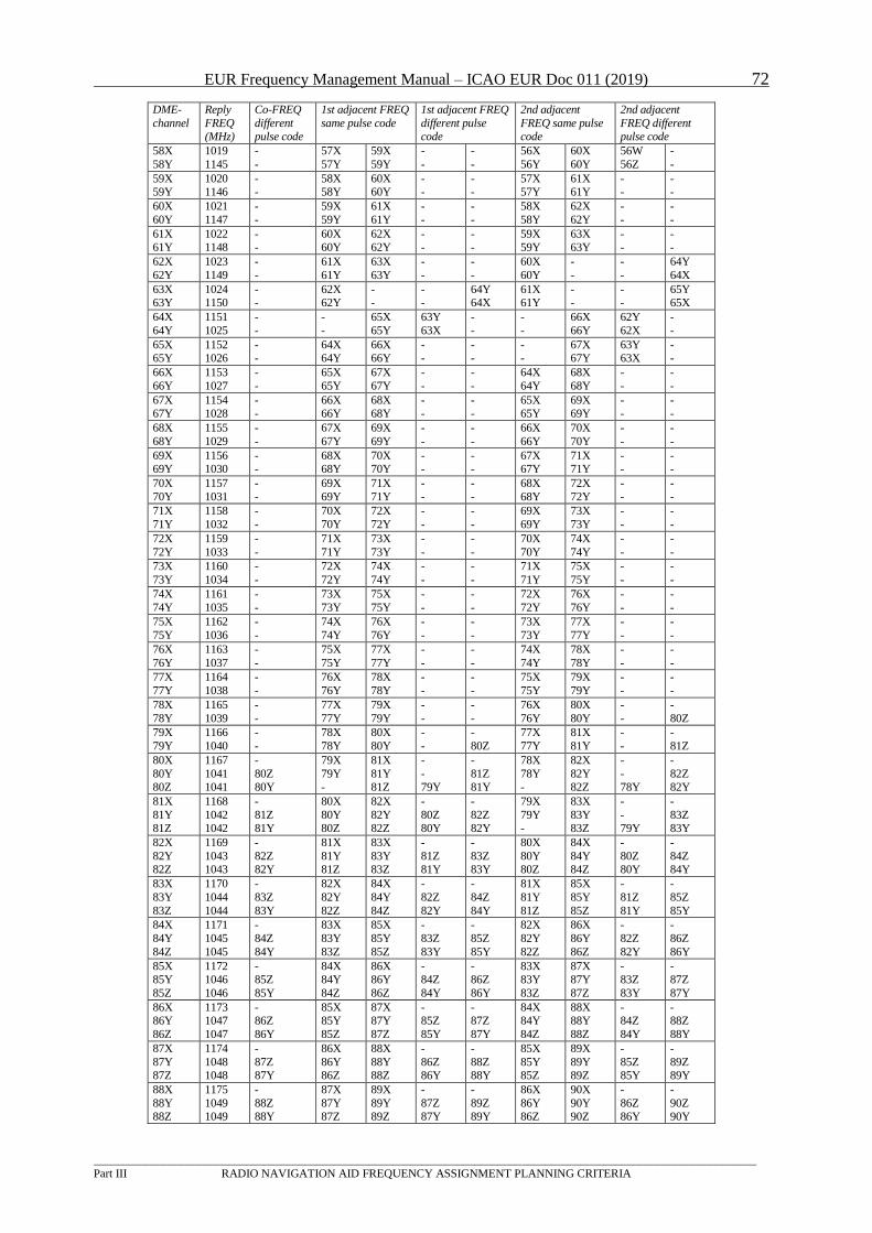
EUR Frequency Management Manual – ICAO EUR Doc 011 (2019) 72
_________________________________________________________________________________________________________________
Part III RADIO NAVIGATION AID FREQUENCY ASSIGNMENT PLANNING CRITERIA
DME-
channel
Reply
FREQ (MHz)
Co-FREQ
different pulse code
1st adjacent FREQ
same pulse code
1st adjacent FREQ
different pulse code
2nd adjacent
FREQ same pulse code
2nd adjacent
FREQ different pulse code
58X
58Y
1019
1145
-
-
57X
57Y
59X
59Y
-
-
-
-
56X
56Y
60X
60Y
56W
56Z
-
-
59X 59Y
1020 1146
- -
58X 58Y
60X 60Y
- -
- -
57X 57Y
61X 61Y
- -
- -
60X
60Y
1021
1147
-
-
59X
59Y
61X
61Y
-
-
-
-
58X
58Y
62X
62Y
-
-
-
-
61X 61Y
1022 1148
- -
60X 60Y
62X 62Y
- -
- -
59X 59Y
63X 63Y
- -
- -
62X
62Y
1023
1149
-
-
61X
61Y
63X
63Y
-
-
-
-
60X
60Y
-
-
-
-
64Y
64X
63X 63Y
1024 1150
- -
62X 62Y
- -
- -
64Y 64X
61X 61Y
- -
- -
65Y 65X
64X
64Y
1151
1025
-
-
-
-
65X
65Y
63Y
63X
-
-
-
-
66X
66Y
62Y
62X
-
-
65X 65Y
1152 1026
- -
64X 64Y
66X 66Y
- -
- -
- -
67X 67Y
63Y 63X
- -
66X
66Y
1153
1027
-
-
65X
65Y
67X
67Y
-
-
-
-
64X
64Y
68X
68Y
-
-
-
-
67X
67Y
1154
1028
-
-
66X
66Y
68X
68Y
-
-
-
-
65X
65Y
69X
69Y
-
-
-
-
68X
68Y
1155
1029
-
-
67X
67Y
69X
69Y
-
-
-
-
66X
66Y
70X
70Y
-
-
-
-
69X 69Y
1156 1030
- -
68X 68Y
70X 70Y
- -
- -
67X 67Y
71X 71Y
- -
- -
70X
70Y
1157
1031
-
-
69X
69Y
71X
71Y
-
-
-
-
68X
68Y
72X
72Y
-
-
-
-
71X
71Y
1158
1032
-
-
70X
70Y
72X
72Y
-
-
-
-
69X
69Y
73X
73Y
-
-
-
-
72X
72Y
1159
1033
-
-
71X
71Y
73X
73Y
-
-
-
-
70X
70Y
74X
74Y
-
-
-
-
73X
73Y
1160
1034
-
-
72X
72Y
74X
74Y
-
-
-
-
71X
71Y
75X
75Y
-
-
-
-
74X
74Y
1161
1035
-
-
73X
73Y
75X
75Y
-
-
-
-
72X
72Y
76X
76Y
-
-
-
-
75X
75Y
1162
1036
-
-
74X
74Y
76X
76Y
-
-
-
-
73X
73Y
77X
77Y
-
-
-
-
76X
76Y
1163
1037
-
-
75X
75Y
77X
77Y
-
-
-
-
74X
74Y
78X
78Y
-
-
-
-
77X
77Y
1164
1038
-
-
76X
76Y
78X
78Y
-
-
-
-
75X
75Y
79X
79Y
-
-
-
-
78X
78Y
1165
1039
-
-
77X
77Y
79X
79Y
-
-
-
-
76X
76Y
80X
80Y
-
-
-
80Z
79X
79Y
1166
1040
-
-
78X
78Y
80X
80Y
-
-
-
80Z
77X
77Y
81X
81Y
-
-
-
81Z
80X
80Y 80Z
1167
1041 1041
-
80Z 80Y
79X
79Y -
81X
81Y 81Z
-
- 79Y
-
81Z 81Y
78X
78Y -
82X
82Y 82Z
-
- 78Y
-
82Z 82Y
81X
81Y 81Z
1168
1042 1042
-
81Z 81Y
80X
80Y 80Z
82X
82Y 82Z
-
80Z 80Y
-
82Z 82Y
79X
79Y -
83X
83Y 83Z
-
- 79Y
-
83Z 83Y
82X
82Y 82Z
1169
1043 1043
-
82Z 82Y
81X
81Y 81Z
83X
83Y 83Z
-
81Z 81Y
-
83Z 83Y
80X
80Y 80Z
84X
84Y 84Z
-
80Z 80Y
-
84Z 84Y
83X
83Y
83Z
1170
1044
1044
-
83Z
83Y
82X
82Y
82Z
84X
84Y
84Z
-
82Z
82Y
-
84Z
84Y
81X
81Y
81Z
85X
85Y
85Z
-
81Z
81Y
-
85Z
85Y
84X
84Y
84Z
1171
1045
1045
-
84Z
84Y
83X
83Y
83Z
85X
85Y
85Z
-
83Z
83Y
-
85Z
85Y
82X
82Y
82Z
86X
86Y
86Z
-
82Z
82Y
-
86Z
86Y
85X 85Y
85Z
1172 1046
1046
- 85Z
85Y
84X 84Y
84Z
86X 86Y
86Z
- 84Z
84Y
- 86Z
86Y
83X 83Y
83Z
87X 87Y
87Z
- 83Z
83Y
- 87Z
87Y
86X 86Y
86Z
1173 1047
1047
- 86Z
86Y
85X 85Y
85Z
87X 87Y
87Z
- 85Z
85Y
- 87Z
87Y
84X 84Y
84Z
88X 88Y
88Z
- 84Z
84Y
- 88Z
88Y
87X
87Y 87Z
1174
1048 1048
-
87Z 87Y
86X
86Y 86Z
88X
88Y 88Z
-
86Z 86Y
-
88Z 88Y
85X
85Y 85Z
89X
89Y 89Z
-
85Z 85Y
-
89Z 89Y
88X
88Y 88Z
1175
1049 1049
-
88Z 88Y
87X
87Y 87Z
89X
89Y 89Z
-
87Z 87Y
-
89Z 89Y
86X
86Y 86Z
90X
90Y 90Z
-
86Z 86Y
-
90Z 90Y
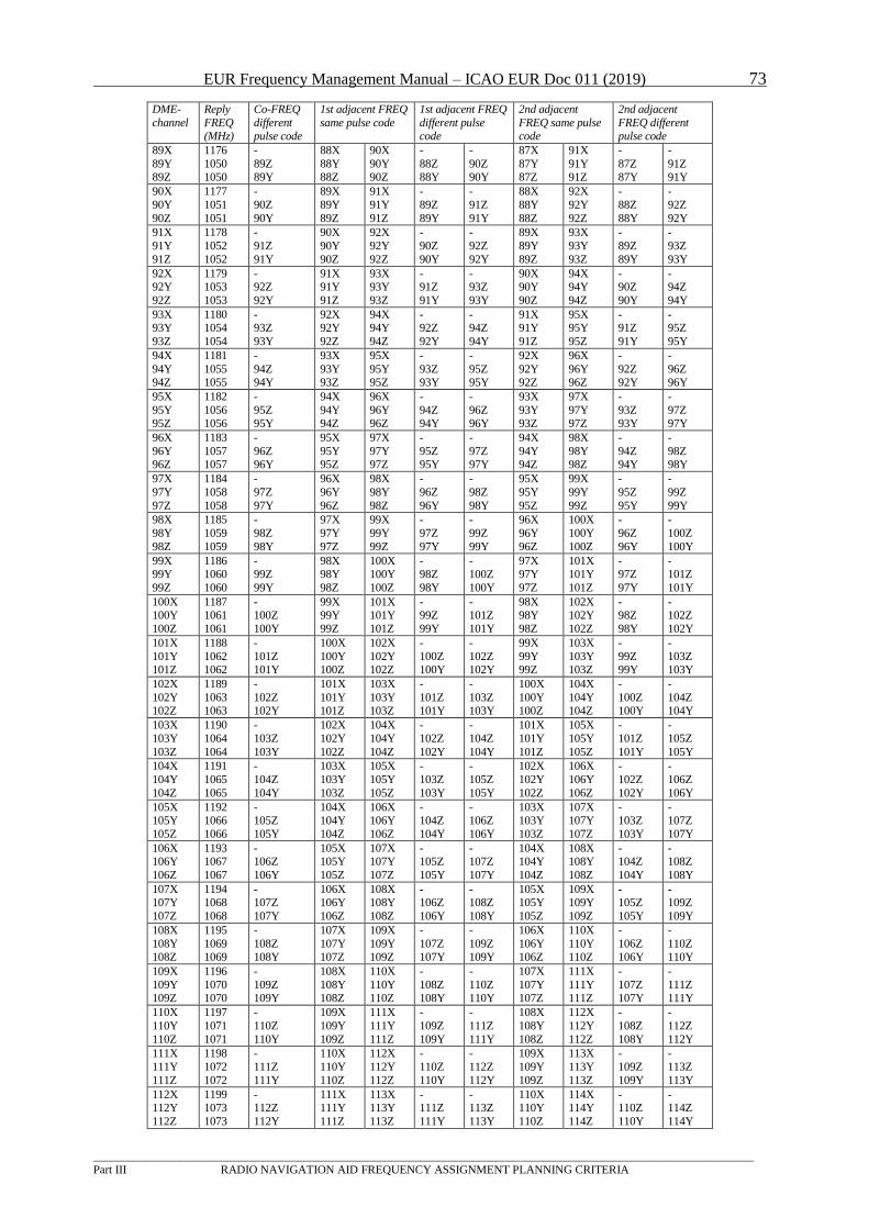
EUR Frequency Management Manual – ICAO EUR Doc 011 (2019) 73
_________________________________________________________________________________________________________________
Part III RADIO NAVIGATION AID FREQUENCY ASSIGNMENT PLANNING CRITERIA
DME-
channel
Reply
FREQ (MHz)
Co-FREQ
different pulse code
1st adjacent FREQ
same pulse code
1st adjacent FREQ
different pulse code
2nd adjacent
FREQ same pulse code
2nd adjacent
FREQ different pulse code
89X
89Y 89Z
1176
1050 1050
-
89Z 89Y
88X
88Y 88Z
90X
90Y 90Z
-
88Z 88Y
-
90Z 90Y
87X
87Y 87Z
91X
91Y 91Z
-
87Z 87Y
-
91Z 91Y
90X
90Y
90Z
1177
1051
1051
-
90Z
90Y
89X
89Y
89Z
91X
91Y
91Z
-
89Z
89Y
-
91Z
91Y
88X
88Y
88Z
92X
92Y
92Z
-
88Z
88Y
-
92Z
92Y
91X
91Y
91Z
1178
1052
1052
-
91Z
91Y
90X
90Y
90Z
92X
92Y
92Z
-
90Z
90Y
-
92Z
92Y
89X
89Y
89Z
93X
93Y
93Z
-
89Z
89Y
-
93Z
93Y
92X 92Y
92Z
1179 1053
1053
- 92Z
92Y
91X 91Y
91Z
93X 93Y
93Z
- 91Z
91Y
- 93Z
93Y
90X 90Y
90Z
94X 94Y
94Z
- 90Z
90Y
- 94Z
94Y
93X 93Y
93Z
1180 1054
1054
- 93Z
93Y
92X 92Y
92Z
94X 94Y
94Z
- 92Z
92Y
- 94Z
94Y
91X 91Y
91Z
95X 95Y
95Z
- 91Z
91Y
- 95Z
95Y
94X
94Y 94Z
1181
1055 1055
-
94Z 94Y
93X
93Y 93Z
95X
95Y 95Z
-
93Z 93Y
-
95Z 95Y
92X
92Y 92Z
96X
96Y 96Z
-
92Z 92Y
-
96Z 96Y
95X
95Y 95Z
1182
1056 1056
-
95Z 95Y
94X
94Y 94Z
96X
96Y 96Z
-
94Z 94Y
-
96Z 96Y
93X
93Y 93Z
97X
97Y 97Z
-
93Z 93Y
-
97Z 97Y
96X
96Y 96Z
1183
1057 1057
-
96Z 96Y
95X
95Y 95Z
97X
97Y 97Z
-
95Z 95Y
-
97Z 97Y
94X
94Y 94Z
98X
98Y 98Z
-
94Z 94Y
-
98Z 98Y
97X
97Y
97Z
1184
1058
1058
-
97Z
97Y
96X
96Y
96Z
98X
98Y
98Z
-
96Z
96Y
-
98Z
98Y
95X
95Y
95Z
99X
99Y
99Z
-
95Z
95Y
-
99Z
99Y
98X
98Y
98Z
1185
1059
1059
-
98Z
98Y
97X
97Y
97Z
99X
99Y
99Z
-
97Z
97Y
-
99Z
99Y
96X
96Y
96Z
100X
100Y
100Z
-
96Z
96Y
-
100Z
100Y
99X 99Y
99Z
1186 1060
1060
- 99Z
99Y
98X 98Y
98Z
100X 100Y
100Z
- 98Z
98Y
- 100Z
100Y
97X 97Y
97Z
101X 101Y
101Z
- 97Z
97Y
- 101Z
101Y
100X 100Y
100Z
1187 1061
1061
- 100Z
100Y
99X 99Y
99Z
101X 101Y
101Z
- 99Z
99Y
- 101Z
101Y
98X 98Y
98Z
102X 102Y
102Z
- 98Z
98Y
- 102Z
102Y
101X
101Y 101Z
1188
1062 1062
-
101Z 101Y
100X
100Y 100Z
102X
102Y 102Z
-
100Z 100Y
-
102Z 102Y
99X
99Y 99Z
103X
103Y 103Z
-
99Z 99Y
-
103Z 103Y
102X
102Y 102Z
1189
1063 1063
-
102Z 102Y
101X
101Y 101Z
103X
103Y 103Z
-
101Z 101Y
-
103Z 103Y
100X
100Y 100Z
104X
104Y 104Z
-
100Z 100Y
-
104Z 104Y
103X
103Y
103Z
1190
1064
1064
-
103Z
103Y
102X
102Y
102Z
104X
104Y
104Z
-
102Z
102Y
-
104Z
104Y
101X
101Y
101Z
105X
105Y
105Z
-
101Z
101Y
-
105Z
105Y
104X
104Y
104Z
1191
1065
1065
-
104Z
104Y
103X
103Y
103Z
105X
105Y
105Z
-
103Z
103Y
-
105Z
105Y
102X
102Y
102Z
106X
106Y
106Z
-
102Z
102Y
-
106Z
106Y
105X 105Y
105Z
1192 1066
1066
- 105Z
105Y
104X 104Y
104Z
106X 106Y
106Z
- 104Z
104Y
- 106Z
106Y
103X 103Y
103Z
107X 107Y
107Z
- 103Z
103Y
- 107Z
107Y
106X 106Y
106Z
1193 1067
1067
- 106Z
106Y
105X 105Y
105Z
107X 107Y
107Z
- 105Z
105Y
- 107Z
107Y
104X 104Y
104Z
108X 108Y
108Z
- 104Z
104Y
- 108Z
108Y
107X 107Y
107Z
1194 1068
1068
- 107Z
107Y
106X 106Y
106Z
108X 108Y
108Z
- 106Z
106Y
- 108Z
108Y
105X 105Y
105Z
109X 109Y
109Z
- 105Z
105Y
- 109Z
109Y
108X
108Y 108Z
1195
1069 1069
-
108Z 108Y
107X
107Y 107Z
109X
109Y 109Z
-
107Z 107Y
-
109Z 109Y
106X
106Y 106Z
110X
110Y 110Z
-
106Z 106Y
-
110Z 110Y
109X
109Y 109Z
1196
1070 1070
-
109Z 109Y
108X
108Y 108Z
110X
110Y 110Z
-
108Z 108Y
-
110Z 110Y
107X
107Y 107Z
111X
111Y 111Z
-
107Z 107Y
-
111Z 111Y
110X
110Y
110Z
1197
1071
1071
-
110Z
110Y
109X
109Y
109Z
111X
111Y
111Z
-
109Z
109Y
-
111Z
111Y
108X
108Y
108Z
112X
112Y
112Z
-
108Z
108Y
-
112Z
112Y
111X
111Y
111Z
1198
1072
1072
-
111Z
111Y
110X
110Y
110Z
112X
112Y
112Z
-
110Z
110Y
-
112Z
112Y
109X
109Y
109Z
113X
113Y
113Z
-
109Z
109Y
-
113Z
113Y
112X 112Y
112Z
1199 1073
1073
- 112Z
112Y
111X 111Y
111Z
113X 113Y
113Z
- 111Z
111Y
- 113Z
113Y
110X 110Y
110Z
114X 114Y
114Z
- 110Z
110Y
- 114Z
114Y
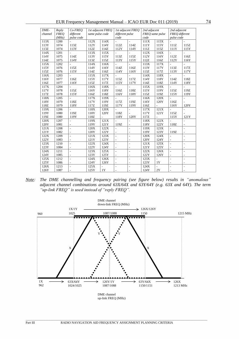
EUR Frequency Management Manual – ICAO EUR Doc 011 (2019) 74
_________________________________________________________________________________________________________________
Part III RADIO NAVIGATION AID FREQUENCY ASSIGNMENT PLANNING CRITERIA
DME-
channel
Reply
FREQ (MHz)
Co-FREQ
different pulse code
1st adjacent FREQ
same pulse code
1st adjacent FREQ
different pulse code
2nd adjacent
FREQ same pulse code
2nd adjacent
FREQ different pulse code
113X
113Y 113Z
1200
1074 1074
-
113Z 113Y
112X
112Y 112Z
114X
114Y 114Z
-
112Z 112Y
-
114Z 114Y
111X
111Y 111Z
115X
115Y 115Z
-
111Z 111Y
-
115Z 115Y
114X
114Y
114Z
1201
1075
1075
-
114Z
114Y
113X
113Y
113Z
115X
115Y
115Z
-
113Z
113Y
-
115Z
115Y
112X
112Y
112Z
116X
116Y
116Z
-
112Z
112Y
-
116Z
116Y
115X
115Y
115Z
1202
1076
1076
-
115Z
115Y
114X
114Y
114Z
116X
116Y
116Z
-
114Z
114Y
-
116Z
116Y
113X
113Y
113Z
117X
117Y
117Z
-
113Z
113Y
-
117Z
117Y
116X 116Y
116Z
1203 1077
1077
- 116Z
116Y
115X 115Y
115Z
117X 117Y
117Z
- 115Z
115Y
- 117Z
117Y
114X 114Y
114Z
118X 118Y
118Z
- 114Z
114Y
- 118Z
118Y
117X 117Y
117Z
1204 1078
1078
- 115Z
115Y
116X 116Y
116Z
118X 118Y
118Z
- 116Z
116Y
- 118Z
118Y
115X 115Y
115Z
119X 119Y
119Z
- 115Z
115Y
- 119Z
119Y
118X
118Y 118Z
1205
1079 1079
-
118Z 118Y
117X
117Y 117Z
119X
119Y 119Z
-
117Z 117Y
-
119Z 119Y
116X
116Y 116Z
120X
120Y -
-
116Z 116Y
-
- 120Y
119X
119Y 119Z
1206
1080 1080
-
119Z 119Y
118X
118Y 118Z
120X
120Y -
-
118Z 118Y
-
-S
120Y
117X
117Y 117Z
121X
121Y -
-
115Z 115Y
-
- 121Y
120X
120Y
1207
1081
-
-
119X
119Y
121X
121Y
-
119Z
-
-
118X
118Y
122X
122Y
-
118Z
-
-
121X 121Y
1208 1082
- -
120X 120Y
122X 122Y
- -
- -
119X 119Y
123X 123Y
- 119Z
- -
122X
122Y
1209
1083
-
-
121X
121Y
123X
123Y
-
-
-
-
120X
120Y
124X
124Y
-
-
-
-
123X 123Y
1210 1084
- -
122X 122Y
124X 124Y
- -
- -
121X 121Y
125X 125Y
- -
- -
124X
124Y
1211
1085
-
-
123X
123Y
125X
125Y
-
-
-
-
122X
122Y
126X
126Y
-
-
-
-
125X 125Y
1212 1086
- -
124X 124Y
126X 126Y
- -
- -
123X 123Y
- 1Y
- -
- -
126X
126Y
1213
1087
-
-
125X
125Y
-
1Y
-
-
-
-
124X
124Y
-
2Y
-
-
-
-
Note: The DME channelling and frequency pairing (see figure below) results in “anomalous”
adjacent channel combinations around 63X/64X and 63Y/64Y (e.g. 63X and 64Y). The term
“up-link FREQ” is used instead of “reply FREQ”.
960
1X/1Y
1025
126X/126Y
11501087/1088
63X/64Y
1024/1025
126Y/1Y
1087/1088
63Y/64X
1150/1151
126X
1213 MHz
1215 MHz
DME channel
down-link FREQ (MHz)
DME channel
up-link FREQ (MHz)
1X
962
X X
Y Y
EUR Frequency Management Manual – ICAO EUR Doc 011 (2019) 75
_________________________________________________________________________________________________________________
Part III RADIO NAVIGATION AID FREQUENCY ASSIGNMENT PLANNING CRITERIA
6 MLS
Note: the MLS material has been temporarily removed, pending conclusion of the on-going
work in various groups. For any additional information on this subject please consult FMG/19
WP02 and the ICAO EUR FMG.
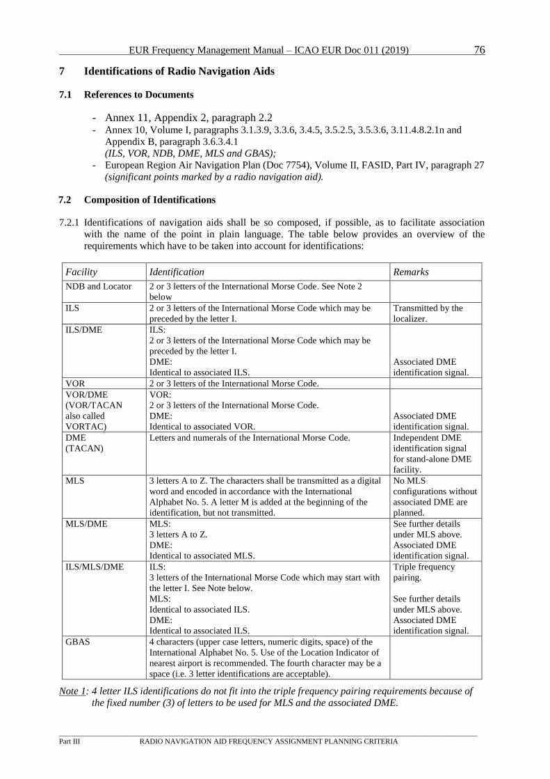
EUR Frequency Management Manual – ICAO EUR Doc 011 (2019) 76
_________________________________________________________________________________________________________________
Part III RADIO NAVIGATION AID FREQUENCY ASSIGNMENT PLANNING CRITERIA
7 Identifications of Radio Navigation Aids
7.1 References to Documents
- Annex 11, Appendix 2, paragraph 2.2 - Annex 10, Volume I, paragraphs 3.1.3.9, 3.3.6, 3.4.5, 3.5.2.5, 3.5.3.6, 3.11.4.8.2.1n and
Appendix B, paragraph 3.6.3.4.1
(ILS, VOR, NDB, DME, MLS and GBAS);
- European Region Air Navigation Plan (Doc 7754), Volume II, FASID, Part IV, paragraph 27
(significant points marked by a radio navigation aid).
7.2 Composition of Identifications
7.2.1 Identifications of navigation aids shall be so composed, if possible, as to facilitate association
with the name of the point in plain language. The table below provides an overview of the
requirements which have to be taken into account for identifications:
Facility Identification Remarks
NDB and Locator 2 or 3 letters of the International Morse Code. See Note 2
below
ILS 2 or 3 letters of the International Morse Code which may be
preceded by the letter I.
Transmitted by the
localizer.
ILS/DME ILS:
2 or 3 letters of the International Morse Code which may be
preceded by the letter I.
DME:
Identical to associated ILS.
Associated DME
identification signal.
VOR 2 or 3 letters of the International Morse Code.
VOR/DME
(VOR/TACAN
also called
VORTAC)
VOR:
2 or 3 letters of the International Morse Code.
DME:
Identical to associated VOR.
Associated DME
identification signal.
DME
(TACAN)
Letters and numerals of the International Morse Code. Independent DME
identification signal
for stand-alone DME
facility.
MLS 3 letters A to Z. The characters shall be transmitted as a digital
word and encoded in accordance with the International
Alphabet No. 5. A letter M is added at the beginning of the
identification, but not transmitted.
No MLS
configurations without
associated DME are
planned.
MLS/DME MLS:
3 letters A to Z.
DME:
Identical to associated MLS.
See further details
under MLS above.
Associated DME
identification signal.
ILS/MLS/DME ILS:
3 letters of the International Morse Code which may start with
the letter I. See Note below.
MLS:
Identical to associated ILS.
DME:
Identical to associated ILS.
Triple frequency
pairing.
See further details
under MLS above.
Associated DME
identification signal.
GBAS 4 characters (upper case letters, numeric digits, space) of the
International Alphabet No. 5. Use of the Location Indicator of
nearest airport is recommended. The fourth character may be a
space (i.e. 3 letter identifications are acceptable).
Note 1: 4 letter ILS identifications do not fit into the triple frequency pairing requirements because of
the fixed number (3) of letters to be used for MLS and the associated DME.
EUR Frequency Management Manual – ICAO EUR Doc 011 (2019) 77
_________________________________________________________________________________________________________________
Part III RADIO NAVIGATION AID FREQUENCY ASSIGNMENT PLANNING CRITERIA
7.2.2 A letter M is added ahead of the MLS identification as described above. This letter M is not
transmitted. Since it is added to all MLS identifications, it does not provide any additional
information which is not already available. It may be useful for operational purposes, but should
not be included in the planning process for identifications of radio navigation aids. With such an
arrangement, it is sufficient to co-ordinate and to register one single identification for each
collocated MLS/DME and ILS/MLS/DME facility.
7.2.3 The identification TST is reserved for radio navigation facilities on test and should not be used for
other purposes.
7.2.4 The two following combinations of letters should not be used for identifications
(FMG Decision 4/2): GAT and OAT.
7.3 Duplication
7.3.1 Duplication of the same identification of a navigation aid should, as far as possible, be avoided in
the EUR Region and in any case should not be permissible for two aids located less than 600 NM
apart. Due to these provisions, an aircraft at the maximum flight level will never be within radio
line-of-sight of more than one radio navigation facility using a specific identification.
7.3.2 The provisions of 7.3.1 above do not apply when two radio navigation aids operating in different
bands of the frequency spectrum are situated at the same location, then their identifications are
normally the same.
7.4 Co-ordination and Registration
7.4.1 Identifications should be subject to co-ordination and registration in the EUR Region in the same
way as frequencies of navigation aids.
EUR Frequency Management Manual – ICAO EUR Doc 011 (2019) 78
_________________________________________________________________________________________________________________
Part III RADIO NAVIGATION AID FREQUENCY ASSIGNMENT PLANNING CRITERIA
8. Non-ICAO Standard Systems operating in Part or in Total within ARNS Bands
RSBN
8.1 RSBN4 is a system that can provide information for APP and En Route Navigation similar as ILS,
VOR, DME and TACAN. RSBN4 uses for one system component the same frequencies as
DME/TACAN operating below channel 40x which is, why interference with DME and TACAN
is possible. This information was already presented as WP12 at the FMG-SG7 meeting in 2004,
but unfortunately no conclusion about further actions were reached. Continued operation could
have also an impact on a future ARNS system in the band.
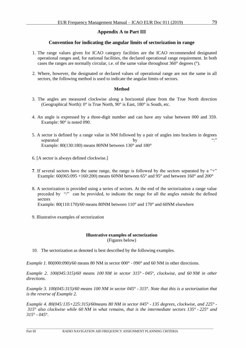
EUR Frequency Management Manual – ICAO EUR Doc 011 (2019) 79
_________________________________________________________________________________________________________________
Part III RADIO NAVIGATION AID FREQUENCY ASSIGNMENT PLANNING CRITERIA
Appendix A to Part III
Convention for indicating the angular limits of sectorization in range
1. The range values given for ICAO category facilities are the ICAO recommended designated
operational ranges and, for national facilities, the declared operational range requirement. In both
cases the ranges are normally circular, i.e. of the same value throughout 360° degrees (°).
2. Where, however, the designated or declared values of operational range are not the same in all
sectors, the following method is used to indicate the angular limits of sectors.
Method
3. The angles are measured clockwise along a horizontal plane from the True North direction
(Geographical North): 0° is True North, 90° is East, 180° is South, etc.
4. An angle is expressed by a three-digit number and can have any value between 000 and 359.
Example: 90° is noted 090.
5. A sector is defined by a range value in NM followed by a pair of angles into brackets in degrees
separated by “:”
Example: 80(130:180) means 80NM between 130° and 180°
6. [A sector is always defined clockwise.]
7. If several sectors have the same range, the range is followed by the sectors separated by a “+”
Example: 60(065:095 +160:200) means 60NM between 65° and 95° and between 160° and 200°
8. A sectorization is provided using a series of sectors. At the end of the sectorization a range value
preceded by “/” can be provided, to indicate the range for all the angles outside the defined
sectors
Example: 80(110:170)/60 means 80NM between 110° and 170° and 60NM elsewhere
9. Illustrative examples of sectorization
Illustrative examples of sectorization
(Figures below)
10. The sectorization as denoted is best described by the following examples.
Example 1. 80(000:090)/60 means 80 NM in sector 000° - 090° and 60 NM in other directions.
Example 2. 100(045:315)/60 means 100 NM in sector 315° - 045°, clockwise, and 60 NM in other
directions.
Example 3. 100(045:315)/60 means 100 NM in sector 045° - 315°. Note that this is a sectorization that
is the reverse of Example 2.
Example 4. 80(045:135+225:315)/60means 80 NM in sector 045° - 135 degrees, clockwise, and 225° -
315° also clockwise while 60 NM in what remains, that is the intermediate sectors 135° - 225° and
315° - 045°.
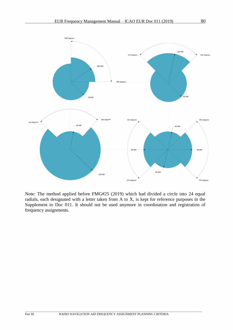
EUR Frequency Management Manual – ICAO EUR Doc 011 (2019) 80
_________________________________________________________________________________________________________________
Part III RADIO NAVIGATION AID FREQUENCY ASSIGNMENT PLANNING CRITERIA
000 degrees
090 degrees
080 NM
60 NM
60 NM
100 NM
045 degrees
135 degrees
80 NM
60 NM
225 degrees
315 degrees
60 NM
80 NM
315 degrees 045 degrees
100 NM
60 NM
Note: The method applied before FMG#25 (2019) which had divided a circle into 24 equal
radials, each designated with a letter taken from A to X, is kept for reference purposes in the
Supplement to Doc 011. It should not be used anymore in coordination and registration of
frequency assignments.
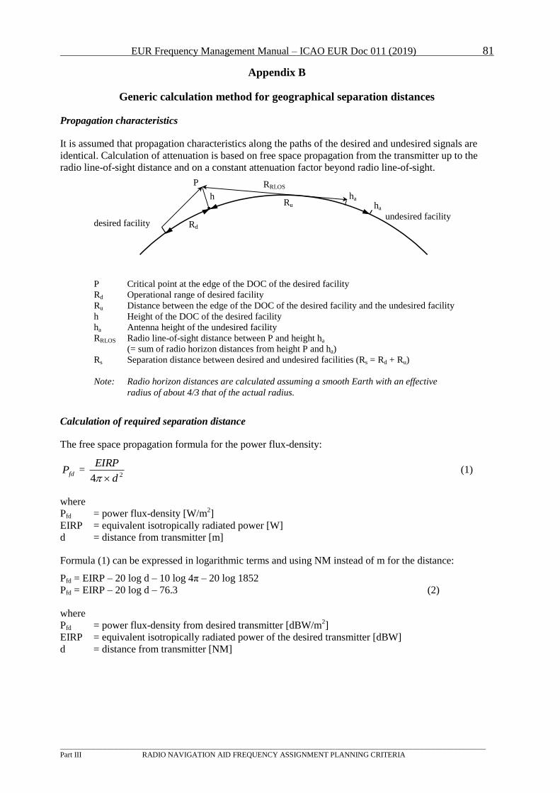
EUR Frequency Management Manual – ICAO EUR Doc 011 (2019) 81
_________________________________________________________________________________________________________________
Part III RADIO NAVIGATION AID FREQUENCY ASSIGNMENT PLANNING CRITERIA
Appendix B
Generic calculation method for geographical separation distances
Propagation characteristics
It is assumed that propagation characteristics along the paths of the desired and undesired signals are
identical. Calculation of attenuation is based on free space propagation from the transmitter up to the
radio line-of-sight distance and on a constant attenuation factor beyond radio line-of-sight.
Calculation of required separation distance
The free space propagation formula for the power flux-density:
fdP = 24 d
EIRP
(1)
where
P Bfd B = power flux-density [W/mP
2P]
EIRP = equivalent isotropically radiated power [W]
d = distance from transmitter [m]
Formula (1) can be expressed in logarithmic terms and using NM instead of m for the distance:
P Bfd B = EIRP – 20 log d – 10 log 4π – 20 log 1852
P Bfd B = EIRP – 20 log d – 76.3 (2)
where
P Bfd B = power flux-density from desired transmitter [dBW/mP
2P]
EIRP = equivalent isotropically radiated power of the desired transmitter [dBW]
d = distance from transmitter [NM]
desired facilityundesired facility
P RRLOS
Rd
Ru
h ha
P Critical point at the edge of the DOC of the desired facility
Rd Operational range of desired facility
Ru Distance between the edge of the DOC of the desired facility and the undesired facility
h Height of the DOC of the desired facility
ha Antenna height of the undesired facility
RRLOS Radio line-of-sight distance between P and height ha
(= sum of radio horizon distances from height P and ha)
Rs Separation distance between desired and undesired facilities (Rs = Rd + Ru)
Note: Radio horizon distances are calculated assuming a smooth Earth with an effective
radius of about 4/3 that of the actual radius.
ha
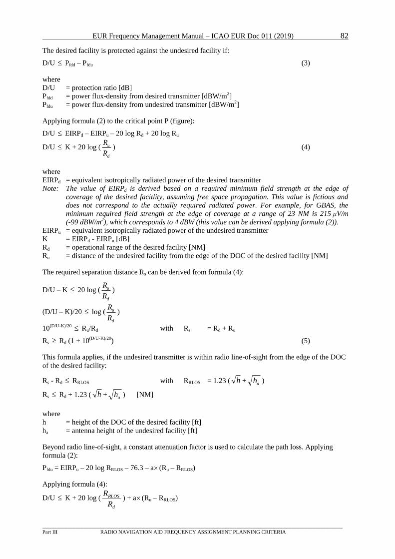
EUR Frequency Management Manual – ICAO EUR Doc 011 (2019) 82
_________________________________________________________________________________________________________________
Part III RADIO NAVIGATION AID FREQUENCY ASSIGNMENT PLANNING CRITERIA
The desired facility is protected against the undesired facility if:
D/U PBfdd B – PBfduB (3)
where
D/U = protection ratio [dB]
P BfddB = power flux-density from desired transmitter [dBW/mP
2P]
P BfduB = power flux-density from undesired transmitter [dBW/mP
2P]
Applying formula (2) to the critical point P (figure):
D/U EIRPBdB – EIRPBuB – 20 log RBdB + 20 log RBuB
D/U K + 20 log (d
u
R
R) (4)
where
EIRP Bd B= equivalent isotropically radiated power of the desired transmitter
Note: The value of EIRPBdB is derived based on a required minimum field strength at the edge of
coverage of the desired facitlity, assuming free space propagation. This value is fictious and
does not correspond to the actually required radiated power. For example, for GBAS, the
minimum required field strength at the edge of coverage at a range of 23 NM is 215 μV/m
(-99 dBW/mP
2P), which corresponds to 4 dBW (this value can be derived applying formula (2)).
EIRP BuB = equivalent isotropically radiated power of the undesired transmitter
K = EIRPBd B - EIRPBuB [dB]
RBdB = operational range of the desired facility [NM]
RBuB = distance of the undesired facility from the edge of the DOC of the desired facility [NM]
The required separation distance RBs B can be derived from formula (4):
D/U – K 20 log (d
u
R
R)
(D/U – K)/20 log (d
u
R
R)
10 P
(D/U-K)/20P RBuB/RBdB with RBs B = RBdB + RBuB
RBs B RBdB (1 + 10P
(D/U-K)/20P) (5)
This formula applies, if the undesired transmitter is within radio line-of-sight from the edge of the DOC
of the desired facility:
RBs B - RBdB RBRLOSB with RBRLOSB = 1.23 ( h + ah )
RBs B RBdB + 1.23 ( h + ah ) [NM]
where
h = height of the DOC of the desired facility [ft]
h Ba B = antenna height of the undesired facility [ft]
Beyond radio line-of-sight, a constant attenuation factor is used to calculate the path loss. Applying
formula (2):
P BfduB = EIRPBuB – 20 log RBRLOSB – 76.3 – a (RBuB – RBRLOSB)
Applying formula (4):
D/U K + 20 log (d
RLOS
R
R) + a (RBuB – RBRLOSB)
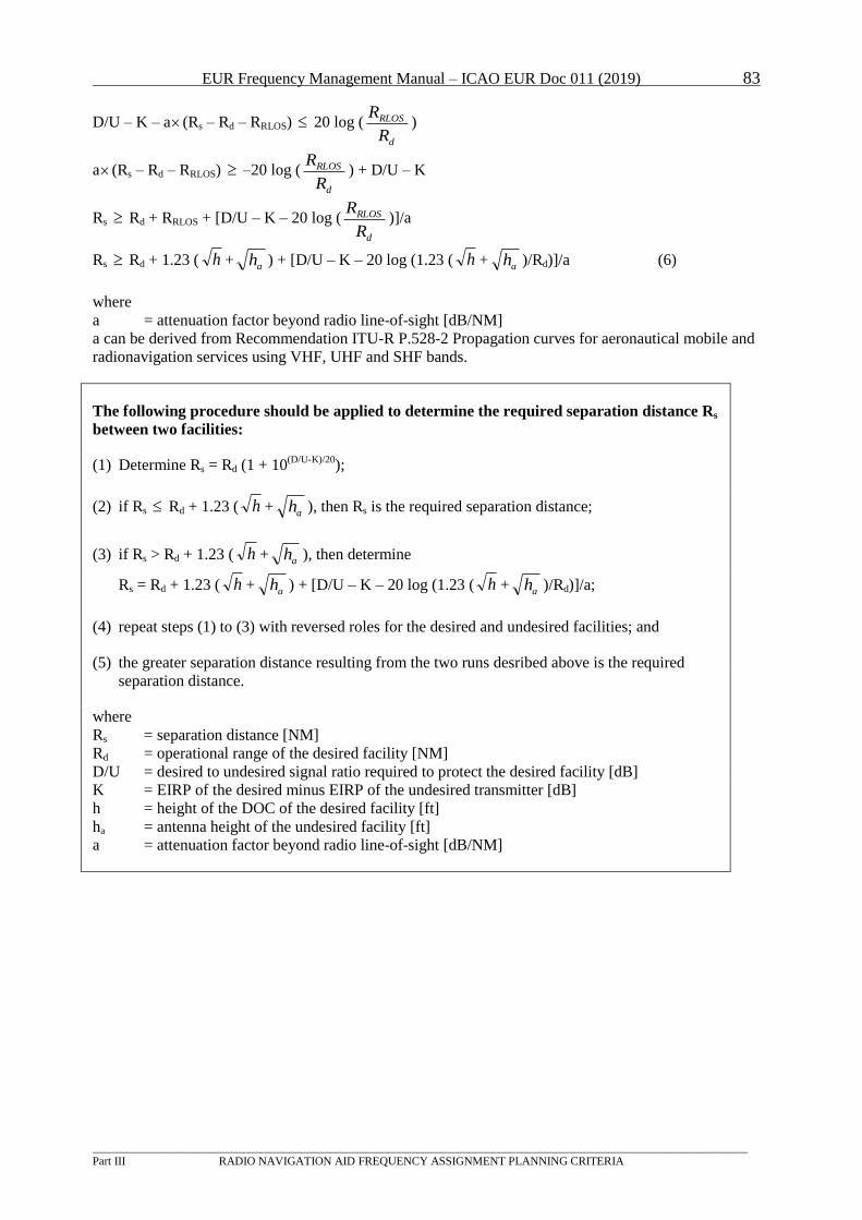
EUR Frequency Management Manual – ICAO EUR Doc 011 (2019) 83
_________________________________________________________________________________________________________________
Part III RADIO NAVIGATION AID FREQUENCY ASSIGNMENT PLANNING CRITERIA
D/U – K – a (RBsB – RBdB – RBRLOSB) 20 log (d
RLOS
R
R)
a (RBs B – RBdB – RBRLOSB) –20 log (d
RLOS
R
R) + D/U – K
RBs B RBdB + RBRLOSB + [D/U – K – 20 log (d
RLOS
R
R)]/a
RBs B RBdB + 1.23 ( h +ah ) + [D/U – K – 20 log (1.23 ( h +
ah )/RBdB)]/a (6)
where
a = attenuation factor beyond radio line-of-sight [dB/NM]
a can be derived from Recommendation ITU-R P.528-2 Propagation curves for aeronautical mobile and
radionavigation services using VHF, UHF and SHF bands.
The following procedure should be applied to determine the required separation distance R Bs B
between two facilities:
(1) Determine RBs B = RBdB (1 + 10P
(D/U-K)/20P);
(2) if RBs B RBdB + 1.23 ( h + ah ), then RBs B is the required separation distance;
(3) if RBs B > RBdB + 1.23 ( h + ah ), then determine
RBs B = RBdB + 1.23 ( h + ah ) + [D/U – K – 20 log (1.23 ( h + ah )/RBdB)]/a;
(4) repeat steps (1) to (3) with reversed roles for the desired and undesired facilities; and
(5) the greater separation distance resulting from the two runs desribed above is the required
separation distance.
where
RBs B = separation distance [NM]
RBdB = operational range of the desired facility [NM]
D/U = desired to undesired signal ratio required to protect the desired facility [dB]
K = EIRP of the desired minus EIRP of the undesired transmitter [dB]
h = height of the DOC of the desired facility [ft]
h Ba B = antenna height of the undesired facility [ft]
a = attenuation factor beyond radio line-of-sight [dB/NM]
EUR Frequency Management Manual – ICAO EUR Doc 011 (2019) 84
_________________________________________________________________________________________________________________
PART IV FREQUENCY CO-ORDINATION AND REGISTRATION PROCEDURES
PART IV FREQUENCY CO-ORDINATION AND REGISTRATION
PROCEDURES
1 Introduction
1.1 Co-ordination and registration procedures for frequency assignments are usually agreed between States
under the rules of the ITU. These procedures are agreed between States in order to assure mutual
acknowledgement of (the status of) each other's frequency assignments and the corresponding rights
and obligations under ITU rules. Within the aeronautical ICAO community in Europe, the FMG has
established co-ordination procedures between States, which can be regarded as mirror procedures to the
formal ITU versions. Although these procedures do not have the same formal status as the original ITU-
ones, in practice they are treated by States concerned in much the same way. This document highlights
the main parties involved in these procedures and their mutual relationship/responsibility.
2 General
2.1 The main part of this document contains the basic co-ordination and registration procedure for use in
the European Region.
2.2 The implementation of co-ordination and registration procedures is supported by SAFIRE, a dedicated
internet-based facility developed and managed by EUROCONTROL on behalf of the FMG and the
Registration Office (ICAO EANPG Conclusion 50/20 refers)*. The performance of SAFIRE is
regularly reviewed by the FMG. States are strongly encouraged to register as users of SAFIRE in order
to increase individual and overall efficiency.
2.3 Co-ordination of new or modified frequency assignments is required with all States concerned that may
be affected by the proposed assignment.
2.4 Special procedures apply if it is necessary to change the frequency of an existing assignment in order to
satisfy a request for a new assignment or for a modification of another existing assignment. In these
circumstances, the co-ordination activity should encompass also the States that may be involved in the
required frequency shifts of existing assignments as well as the States that may be concerned with these
frequency shifts. EUROCONTROL has established on behalf of the FMG specialized co-ordination
mechanisms for the satisfaction of such frequency requests. States are encouraged to request the support
of EUROCONTROL when faced with such frequency requests.
2.5 The ICAO Paris Office would be available to assist States in resolving any co-ordination difficulties or
disputes.
* EANPG Conclusion 50/20 - Implementation of the SAFIRE for COM2 coordination:
That starting on 1 January 2009, the on-line system SAFIRE be used as the only means of frequency assignments
coordination and registration for COM2 Tables in the ICAO EUR Region.
EUR Frequency Management Manual – ICAO EUR Doc 011 (2019) 85
_________________________________________________________________________________________________________________
PART IV FREQUENCY CO-ORDINATION AND REGISTRATION PROCEDURES
3 Basic Co-ordination and Registration Procedures for Aeronautical Frequency
Assignments
3.1 The basic procedure for the co-ordination and registration of aeronautical frequency assignments is
depicted in the figure of Section 3 of Part I of this manual (page 3). As can be seen from this, the main
parties involved are:
1) States having a requirement for an addition or modification of an assignment to a service;
2) all States concerned with a proposed new assignment or modification of an existing
assignment to a service;
3) the Registration Office (ICAO EUR/NAT Office).
It is clarified that in the co-ordination and registration process participate also States from adjacent
ICAO regions.
3.2 For the implementation of the co-ordination and registration procedures described below, the following
arrangements apply:
1) States registered to SAFIRE for a given category (COM2, COM3, COM4) of assignments
(referred to as SAFIRE States henceforth) make mandatorily use of the appropriate utilities of
the facility. Under normal conditions,, SAFIRE States are expected to execute their tasks
exclusively on SAFIRE.
2) States not registered to SAFIRE for a given category of assignments (referred to as non-
SAFIRE States henceforth) should exchange co-ordination and registration messages as
described in the following paragraph.
3) With the exception of bilateral negotiations, the exchange of information between a SAFIRE
State and a non-SAFIRE State or between two non-SAFIRE States is effected through the
mediation of the Registration Office. In particular, requests, reactions or notifications of non-
SAFIRE States which concern SAFIRE States or other non-SAFIRE States are sent to the
Registration Office, which in turn produces the appropriate entries into SAFIRE. Conversely
for requests, reactions or notifications of SAFIRE or non-SAFIRE States which concern non-
SAFIRE States, the Registration Office retrieves the corresponding information entered in
SAFIRE and generates the appropriate messages to the non-SAFIRE States concerned. In
their communication with the Registration Office for co-ordination and registration purposes,
non-SAFIRE States may usethe dedicated e-mail address [email protected].
4) For the distribution of co-ordination-related material entered in SAFIRE to concerned non-
SAFIRE States the Registration Office is supported by automation. Unless a non-SAFIRE
State informs the Registration Office of the list of SAFIRE States from which it wishes to
receive co-ordination-related messages, the Registration Office shall forward to such non
SAFIRE State all SAFIRE co-ordination-related messages.
3.3 The various actions and responsibilities of each of the parties in the co-ordination and registration
procedures are described in the paragraphs below.
3.4 A State having a requirement for an addition/modification of an assignment to a service is responsible
for:
EUR Frequency Management Manual – ICAO EUR Doc 011 (2019) 86
_________________________________________________________________________________________________________________
PART IV FREQUENCY CO-ORDINATION AND REGISTRATION PROCEDURES
a) the request for co-ordination and registration to be submitted to all States concerned and the
Registration Office (Note: Proposals establish priority with respect to their provisional protection
according to their time of submission to the Registration Office);
b) in case any objections are raised:
i) negotiating with objecting State(s) on details of the proposed assignment with a view to solving
identified incompatibilities; or
ii) the withdrawal of the objected proposal and corresponding notification to all States concerned
and the Registration Office
Note 1: In case of objection, requesting States may extend their bilateral negotiations with objecting States
beyond the 4-week period of paragraph 3.7 b) up until 3 months from the submission of the co-
ordination request.
Note 2: Requests for modifications of the remarks field or of the location name field as well as VHF COM
conversions to 8.33 kHz channel spacing on the same frequency may reach the Registration Office
without prior co-ordination.
Note 3: Care of the Registration Office, objected proposals, , are deleted from the pertinent databases after
the lapse of 3 months from their submission. Objected proposals under investigation by the
Registration Office are not subject to removal.
3.5 Deletions of assignments are submitted to the Registration Office and notified to all States concerned.
3.6 All States concerned with a possible impact of a proposed addition/modification of an assignment on
one or more of their registered assignments or proposals are responsible for:
a) the protection of their registered assignments and proposals against incompatibility with the
proposed addition/modification;
b) the proper reaction to the requesting State and the Registration Office, based on the
examination of a proposal as above, within 4 weeks from the notification of the co-ordination
request (Note: No answer by the target date will be taken as an approval); and
c) the proper reaction to the requesting State and the Registration Office in the eventof an
improperly registered proposal.
Note 1: Valid objections can be raised against proposals which do not contain all information required for
compatibility assessment or contain implausible data (e.g. frequencies not complying with the
appropriate pairing tables, in the case of paired services).
3.7 After the lapse of the 4-week period of paragraph 3.6b), non-objected proposals are registered in the
appropriate ICAO EUR COM table of frequency assignments. Objected proposals are registered in the
appropriate table only after all objections to these proposals are withdrawn.
Note 1: If bilateral negotiations are foreseen to last longer than 4 weeks, States having valid concerns
about a proposal are advised to object this proposal, without prejudice to the outcome of the
negotiations.
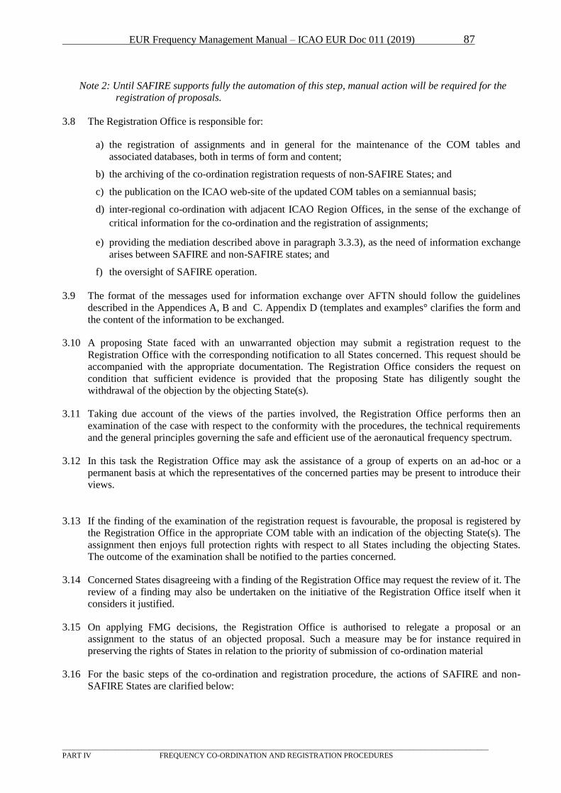
EUR Frequency Management Manual – ICAO EUR Doc 011 (2019) 87
_________________________________________________________________________________________________________________
PART IV FREQUENCY CO-ORDINATION AND REGISTRATION PROCEDURES
Note 2: Until SAFIRE supports fully the automation of this step, manual action will be required for the
registration of proposals.
3.8 The Registration Office is responsible for:
a) the registration of assignments and in general for the maintenance of the COM tables and
associated databases, both in terms of form and content;
b) the archiving of the co-ordination registration requests of non-SAFIRE States; and
c) the publication on the ICAO web-site of the updated COM tables on a semiannual basis;
d) inter-regional co-ordination with adjacent ICAO Region Offices, in the sense of the exchange of
critical information for the co-ordination and the registration of assignments;
e) providing the mediation described above in paragraph 3.3.3), as the need of information exchange
arises between SAFIRE and non-SAFIRE states; and
f) the oversight of SAFIRE operation.
3.9 The format of the messages used for information exchange over AFTN should follow the guidelines
described in the Appendices A, B and C. Appendix D (templates and examples° clarifies the form and
the content of the information to be exchanged.
3.10 A proposing State faced with an unwarranted objection may submit a registration request to the
Registration Office with the corresponding notification to all States concerned. This request should be
accompanied with the appropriate documentation. The Registration Office considers the request on
condition that sufficient evidence is provided that the proposing State has diligently sought the
withdrawal of the objection by the objecting State(s).
3.11 Taking due account of the views of the parties involved, the Registration Office performs then an
examination of the case with respect to the conformity with the procedures, the technical requirements
and the general principles governing the safe and efficient use of the aeronautical frequency spectrum.
3.12 In this task the Registration Office may ask the assistance of a group of experts on an ad-hoc or a
permanent basis at which the representatives of the concerned parties may be present to introduce their
views.
3.13 If the finding of the examination of the registration request is favourable, the proposal is registered by
the Registration Office in the appropriate COM table with an indication of the objecting State(s). The
assignment then enjoys full protection rights with respect to all States including the objecting States.
The outcome of the examination shall be notified to the parties concerned.
3.14 Concerned States disagreeing with a finding of the Registration Office may request the review of it. The
review of a finding may also be undertaken on the initiative of the Registration Office itself when it
considers it justified.
3.15 On applying FMG decisions, the Registration Office is authorised to relegate a proposal or an
assignment to the status of an objected proposal. Such a measure may be for instance required in
preserving the rights of States in relation to the priority of submission of co-ordination material
3.16 For the basic steps of the co-ordination and registration procedure, the actions of SAFIRE and non-
SAFIRE States are clarified below:

EUR Frequency Management Manual – ICAO EUR Doc 011 (2019) 88
_________________________________________________________________________________________________________________
PART IV FREQUENCY CO-ORDINATION AND REGISTRATION PROCEDURES
Non-SAFIRE States SAFIRE States
Submission of a
proposal
Send appropriate message to the
Registration Office
Make appropriate entry
into SAFIRE
Reaction to a
proposal
Send appropriate message to the
Registration Office
Make appropriate entry
into SAFIRE
Registration
request for a
proposal
Send appropriate message to the
Registration Office
Make appropriate entry
into SAFIRE
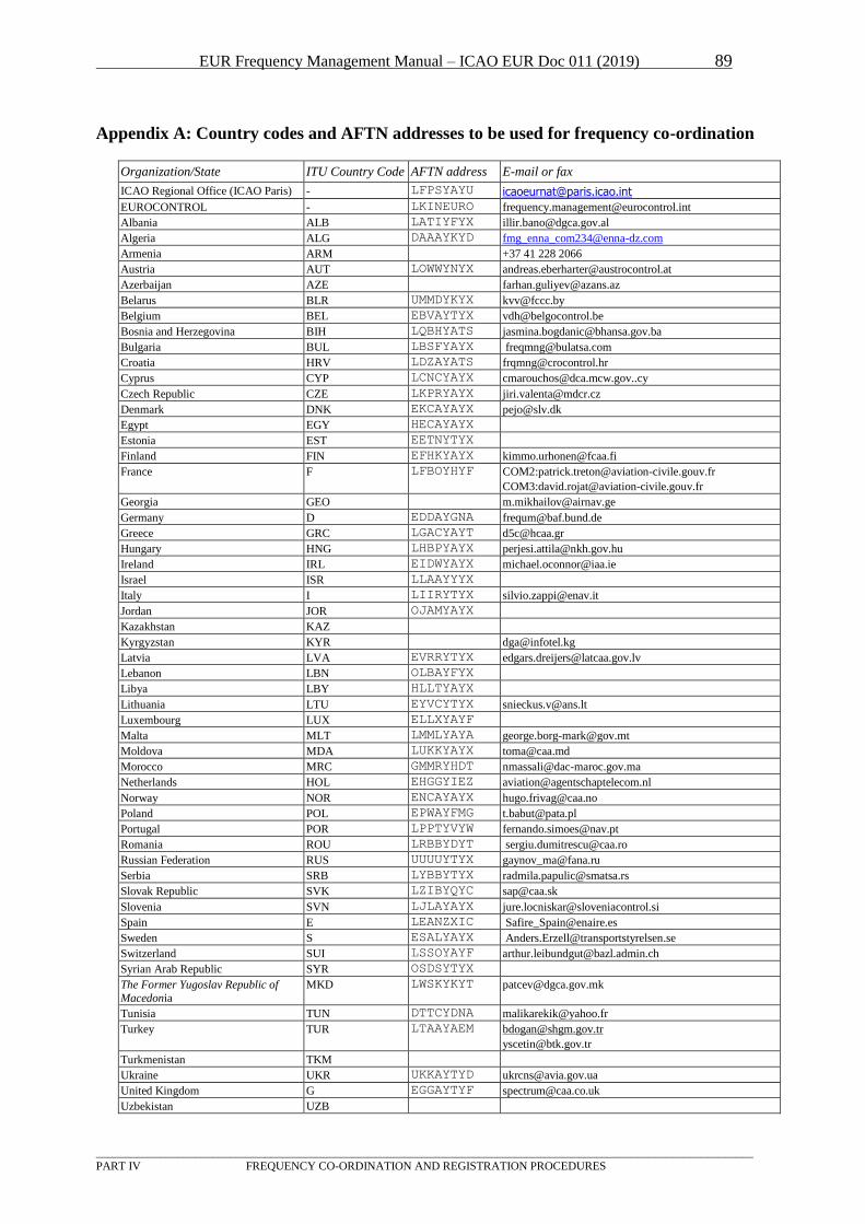
EUR Frequency Management Manual – ICAO EUR Doc 011 (2019) 89
_________________________________________________________________________________________________________________
PART IV FREQUENCY CO-ORDINATION AND REGISTRATION PROCEDURES
Appendix A: Country codes and AFTN addresses to be used for frequency co-ordination
Organization/State ITU Country Code AFTN address E-mail or fax
ICAO Regional Office (ICAO Paris) - LFPSYAYU [email protected]
EUROCONTROL - LKINEURO [email protected]
Albania ALB LATIYFYX [email protected]
Algeria ALG DAAAYKYD [email protected]
Armenia ARM +37 41 228 2066
Austria AUT LOWWYNYX [email protected]
Azerbaijan AZE [email protected]
Belarus BLR UMMDYKYX [email protected]
Belgium BEL EBVAYTYX [email protected]
Bosnia and Herzegovina BIH LQBHYATS [email protected]
Bulgaria BUL LBSFYAYX [email protected]
Croatia HRV LDZAYATS [email protected]
Cyprus CYP LCNCYAYX [email protected]
Czech Republic CZE LKPRYAYX [email protected]
Denmark DNK EKCAYAYX [email protected]
Egypt EGY HECAYAYX
Estonia EST EETNYTYX
Finland FIN EFHKYAYX [email protected]
France F LFBOYHYF COM2:[email protected]
COM3:[email protected]
Georgia GEO [email protected]
Germany D EDDAYGNA [email protected]
Greece GRC LGACYAYT [email protected]
Hungary HNG LHBPYAYX [email protected]
Ireland IRL EIDWYAYX [email protected]
Israel ISR LLAAYYYX
Italy I LIIRYTYX [email protected]
Jordan JOR OJAMYAYX
Kazakhstan KAZ
Kyrgyzstan KYR [email protected]
Latvia LVA EVRRYTYX [email protected]
Lebanon LBN OLBAYFYX
Libya LBY HLLTYAYX
Lithuania LTU EYVCYTYX [email protected]
Luxembourg LUX ELLXYAYF
Malta MLT LMMLYAYA [email protected]
Moldova MDA LUKKYAYX [email protected]
Morocco MRC GMMRYHDT [email protected]
Netherlands HOL EHGGYIEZ [email protected]
Norway NOR ENCAYAYX [email protected]
Poland POL EPWAYFMG [email protected]
Portugal POR LPPTYVYW [email protected]
Romania ROU LRBBYDYT [email protected]
Russian Federation RUS UUUUYTYX [email protected]
Serbia SRB LYBBYTYX [email protected]
Slovak Republic SVK LZIBYQYC [email protected]
Slovenia SVN LJLAYAYX [email protected]
Spain E LEANZXIC [email protected]
Sweden S ESALYAYX [email protected]
Switzerland SUI LSSOYAYF [email protected]
Syrian Arab Republic SYR OSDSYTYX
The Former Yugoslav Republic of
Macedonia
MKD LWSKYKYT [email protected]
Tunisia TUN DTTCYDNA [email protected]
Turkey TUR LTAAYAEM [email protected]
Turkmenistan TKM
Ukraine UKR UKKAYTYD [email protected]
United Kingdom G EGGAYTYF [email protected]
Uzbekistan UZB
EUR Frequency Management Manual – ICAO EUR Doc 011 (2019) 90
_________________________________________________________________________________________________________________
PART IV FREQUENCY CO-ORDINATION AND REGISTRATION PROCEDURES
Note 1: E-mail and fax are the only method of communication with ICAO EUR/NAT Office
Note2: Proposals for the assignment of frequencies or identifications have to be addressed to States
concerned. However, the following States would like to get copies of all proposals and registration
messages: BEL, D, F, G and HRV.
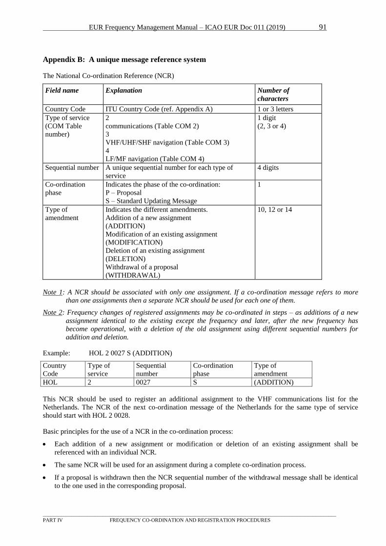
EUR Frequency Management Manual – ICAO EUR Doc 011 (2019) 91
_________________________________________________________________________________________________________________
PART IV FREQUENCY CO-ORDINATION AND REGISTRATION PROCEDURES
Appendix B: A unique message reference system
The National Co-ordination Reference (NCR)
Field name Explanation Number of
characters
Country Code ITU Country Code (ref. Appendix A) 1 or 3 letters
Type of service
(COM Table
number)
2
communications (Table COM 2)
3
VHF/UHF/SHF navigation (Table COM 3)
4
LF/MF navigation (Table COM 4)
1 digit
(2, 3 or 4)
Sequential number A unique sequential number for each type of
service
4 digits
Co-ordination
phase
Indicates the phase of the co-ordination:
P – Proposal
S – Standard Updating Message
1
Type of
amendment
Indicates the different amendments.
Addition of a new assignment
(ADDITION)
Modification of an existing assignment
(MODIFICATION)
Deletion of an existing assignment
(DELETION)
Withdrawal of a proposal
(WITHDRAWAL)
10, 12 or 14
Note 1: A NCR should be associated with only one assignment. If a co-ordination message refers to more
than one assignments then a separate NCR should be used for each one of them.
Note 2: Frequency changes of registered assignments may be co-ordinated in steps – as additions of a new
assignment identical to the existing except the frequency and later, after the new frequency has
become operational, with a deletion of the old assignment using different sequential numbers for
addition and deletion.
Example: HOL 2 0027 S (ADDITION)
Country
Code
Type of
service
Sequential
number
Co-ordination
phase
Type of
amendment
HOL 2 0027 S (ADDITION)
This NCR should be used to register an additional assignment to the VHF communications list for the
Netherlands. The NCR of the next co-ordination message of the Netherlands for the same type of service
should start with HOL 2 0028.
Basic principles for the use of a NCR in the co-ordination process:
Each addition of a new assignment or modification or deletion of an existing assignment shall be
referenced with an individual NCR.
The same NCR will be used for an assignment during a complete co-ordination process.
If a proposal is withdrawn then the NCR sequential number of the withdrawal message shall be identical
to the one used in the corresponding proposal.
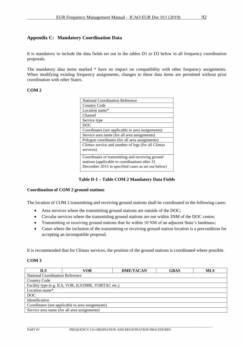
EUR Frequency Management Manual – ICAO EUR Doc 011 (2019) 92
_________________________________________________________________________________________________________________
PART IV FREQUENCY CO-ORDINATION AND REGISTRATION PROCEDURES
Appendix C: Mandatory Coordination Data
It is mandatory to include the data fields set out in the tables D1 to D3 below in all frequency coordination
proposals.
The mandatory data items marked * have no impact on compatibility with other frequency assignments.
When modifying existing frequency assignments, changes to these data items are permitted without prior
coordination with other States.
COM 2
National Coordination Reference
Country Code
Location name*
Channel
Service type
DOC
Coordinates (not applicable to area assignments)
Service area name (for all area assignments)
Polygon coordinates (for all area assignments)
Climax service and number of legs (for all Climax
services)
Coordinates of transmitting and receiving ground
stations (applicable to coordinations after 31
December 2015 in specified cases as set out below)
Table D-1 – Table COM 2 Mandatory Data Fields
Coordination of COM 2 ground stations
The location of COM 2 transmitting and receiving ground stations shall be coordinated in the following cases:
Area services where the transmitting ground stations are outside of the DOC;
Circular services where the transmitting ground stations are not within 3NM of the DOC centre;
Transmitting or receiving ground stations that lie within 10 NM of an adjacent State’s landmass;
Cases where the inclusion of the transmitting or receiving ground station location is a precondition for
accepting an incompatible proposal.
It is recommended that for Climax services, the position of the ground stations is coordinated where possible.
COM 3
ILS VOR DME/TACAN GBAS MLS
National Coordination Reference
Country Code
Facility type (e.g. ILS, VOR, ILS/DME, VORTAC etc.)
Location name*
DOC
Identification
Coordinates (not applicable to area assignments)
Service area name (for all area assignments)
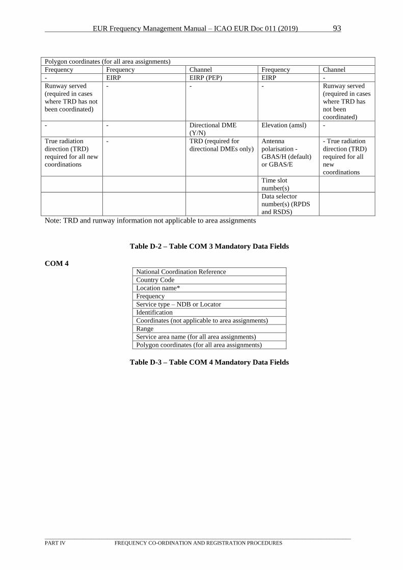
EUR Frequency Management Manual – ICAO EUR Doc 011 (2019) 93
_________________________________________________________________________________________________________________
PART IV FREQUENCY CO-ORDINATION AND REGISTRATION PROCEDURES
Polygon coordinates (for all area assignments)
Frequency Frequency Channel Frequency Channel
- EIRP EIRP (PEP) EIRP -
Runway served
(required in cases
where TRD has not
been coordinated)
- - - Runway served
(required in cases
where TRD has
not been
coordinated)
- - Directional DME
(Y/N)
Elevation (amsl) -
True radiation
direction (TRD)
required for all new
coordinations
- TRD (required for
directional DMEs only)
Antenna
polarisation -
GBAS/H (default)
or GBAS/E
- True radiation
direction (TRD)
required for all
new
coordinations
Time slot
number(s)
Data selector
number(s) (RPDS
and RSDS)
Note: TRD and runway information not applicable to area assignments
Table D-2 – Table COM 3 Mandatory Data Fields
COM 4 National Coordination Reference
Country Code
Location name*
Frequency
Service type – NDB or Locator
Identification
Coordinates (not applicable to area assignments)
Range
Service area name (for all area assignments)
Polygon coordinates (for all area assignments)
Table D-3 – Table COM 4 Mandatory Data Fields
EUR Frequency Management Manual – ICAO EUR Doc 011 (2019) 94
_________________________________________________________________________________________________________________
PART IV FREQUENCY CO-ORDINATION AND REGISTRATION PROCEDURES
4 Procedure to allocate or request a New UHF Channel for ATC Communications in GAT
4.1 General Overview
4.1.1 The UHF band (225-400 MHz) within NATO Member States is collectively managed by the NATO
Frequency Management Sub-Committee (FMSC), with the technical and administrative support of the
Spectrum Management Branch (SMB) which is a permanent Staff located at NATO Headquarters
(NATO HQ), Brussels.
4.1.2 When a request for assignment in the UHF band is received at SMB, it will be checked for correctness
and run through the NUFAS tool (NATO UHF Assignment Software) that will identify a proper UHF
channel taking into account all geographical, technical and administrative details provided in the
request. Once the frequency is identified and assigned, the assignment record is stored in the SMB
database and a copy is sent back to the national agency (NARFA or equivalent office) of the
requesting State (CASE 1 for NATO State or CASE 2 for Non NATO State).
Important Note:
Since the band is managed centrally by SMB which maintains a central database of all UHF
Air/Ground/Air assignments, the Nations do not normally nominate or propose frequencies in the
requests; SMB assigns directly the best suitable frequency for the request.
4.2 Case 1: For NATO Member States
4.2.1 The procedure for NATO Member States to get a deconflicted frequency assignment in the NATO
UHF band (225-400 MHz) is governed by a NATO Agreement which is of application throughout
NATO Europe. Every NATO Member State has within its Ministry of Defence a National Radio
Frequency Agency (NARFA), or equivalent office, which acts as the point of contact between the
Nation and the SMB at NATO HQ. NARFAs collect requests from their National Users, either
military or civilian, willing to operate in the UHF band, and forward them to the SMB. The format of
the request coming from the national users to its NARFA is a national decision, but the format of the
request forwarded to SMB must use the NATO “Spectrum Management Allied Data Exchange
Format” (SMADEF). A free software tool (ARCADE), is distributed by SMB to help producing
requests in SMADEF form.
4.3 Case 2: For Non NATO Members
4.3.1. These States that are not Member of NATO but that belong to EUR/NAT ICAO Region may also get
support from the SMB at NATO HQ in the process of deconflicting UHF channels to be used for
Civilian Communications. This deconfliction is necessary due to the large coordination distances
involved to avoid interferences.
4.3.2 The Appendix A is a simplified request form, based on the information normally provided in SMADEF
format. It lists the information that, as a minimum, is necessary to the SMB to run their Frequency
Assignment System in order to identify an available UHF channel. This form may be subject to changes
that will be notified by NATO as necessary. An example of a filled-in questionnaire is also attached.
Notes:
1. Other information may be required by SMB from those States on a case by case basis and this
will be done by bilateral coordination with the Point Of Contact mentioned in the request form.
2. Non NATO Member States who wish it are free to use the full SMADEF format and associated
free software tool ARCADE, in place of the simplified form at Appendix X.
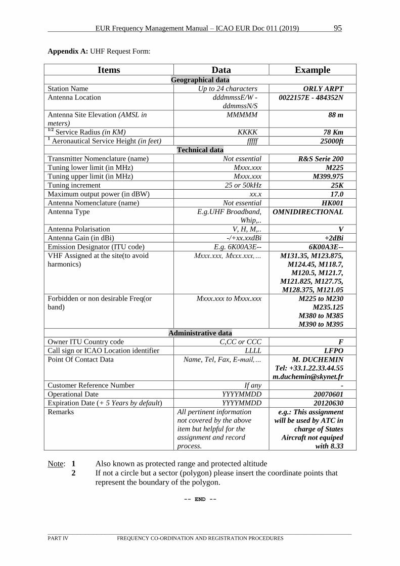
EUR Frequency Management Manual – ICAO EUR Doc 011 (2019) 95
_________________________________________________________________________________________________________________ PART IV FREQUENCY CO-ORDINATION AND REGISTRATION PROCEDURES
Appendix A: UHF Request Form:
Items Data Example Geographical data
Station Name Up to 24 characters ORLY ARPT
Antenna Location dddmmssE/W -
ddmmssN/S 0022157E - 484352N
Antenna Site Elevation (AMSL in
meters)
MMMMM 88 m
1/2 Service Radius (in KM) KKKK 78 Km
1 Aeronautical Service Height (in feet) fffff 25000ft
Technical data
Transmitter Nomenclature (name) Not essential R&S Serie 200
Tuning lower limit (in MHz) Mxxx.xxx M225
Tuning upper limit (in MHz) Mxxx.xxx M399.975
Tuning increment 25 or 50kHz 25K
Maximum output power (in dBW) xx.x 17.0
Antenna Nomenclature (name) Not essential HK001
Antenna Type E.g.UHF Broadband,
Whip,.. OMNIDIRECTIONAL
Antenna Polarisation V, H, M,.. V
Antenna Gain (in dBi) -/+xx.xxdBi +2dBi
Emission Designator (ITU code) E.g. 6K00A3E-- 6K00A3E--
VHF Assigned at the site(to avoid
harmonics)
Mxxx.xxx, Mxxx.xxx,… M131.35, M123.875,
M124.45, M118.7,
M120.5, M121.7,
M121.825, M127.75,
M128.375, M121.05
Forbidden or non desirable Freq(or
band)
Mxxx.xxx to Mxxx.xxx M225 to M230
M235.125
M380 to M385
M390 to M395
Administrative data
Owner ITU Country code C,CC or CCC F
Call sign or ICAO Location identifier LLLL LFPO
Point Of Contact Data Name, Tel, Fax, E-mail,… M. DUCHEMIN
Tel: +33.1.22.33.44.55
Customer Reference Number If any -
Operational Date YYYYMMDD 20070601
Expiration Date (+ 5 Years by default) YYYYMMDD 20120630
Remarks All pertinent information
not covered by the above
item but helpful for the
assignment and record
process.
e.g.: This assignment
will be used by ATC in
charge of States
Aircraft not equiped
with 8.33
Note: 1 Also known as protected range and protected altitude
2 If not a circle but a sector (polygon) please insert the coordinate points that
represent the boundary of the polygon.
-- END --