Understanding Addiction: Yours, Mine and Ours H.E. Logue, M.D.

DELTA
Venlighedsvej 4
2970 Hørsholm
Denmark
Tel. (+45) 72 19 40 00
Fax (+45) 72 19 40 01
www.delta.dk
www.madebydelta.com
VAT No. DK55117314
EU Type Examination Certificate
No. DK0199.486 Revision 1
DAD14x.y
NON-AUTOMATIC WEIGHING INSTRUMENT
Issued by DELTA Danish Electronics, Light & Acoustics
EU - Notified Body No. 0199
In accordance with the requirements in Directive 2014/31/EU of the European Parliament and
Council.
Issued to Flintec GmbH
Bemannsbruch 9
74909 Meckesheim
GERMANY
In respect of Non-automatic weighing instrument designated DAD14x.y with variants of
modules of load receptors, load cells and peripheral equipment.
Accuracy class III and IIII
Maximum capacity, Max: From 0.5 kg up to 500 000 kg
Verification scale interval: e = Max / n
Maximum number of verification scale intervals: n ≤ 10000 for single-interval
(however, dependent on environment and the composition of the modules).
Minimum input voltage per VSI: 0.2 µV
Variants of modules and conditions for the composition of the modules are set
out in the annex.
The conformity with the essential requirements in annex 1 of the Directive is met by the appli-
cation of the European Standard EN 45501:2015, OIML R76:2006 and WELMEC Guide
2.1:2001.
Note: This certificate is a revised edition. which replaces previous revisions and extend
the validation period.
The principal characteristics and approval conditions are set out in the descriptive
annex to this certificate.
The annex comprises 11 pages.
Issued on 2017-04-28
Valid until 2027-04-28 Signatory: J. Hovgård

Annex page 1 of 11 EU Type Examination Certificate no. DK0199.486 rev.1
Issued by DELTA – A PART OF FORCE TECHNOLOGY
Descriptive annex
Contents Page
1. Name and type of instrument and modules 2
2. Description of the construction and function 2
2.1 Construction 2
2.2 Functions 3
3. Technical data 4
3.1 Indicator 4
3.2 Load receptors, load cells, and load receptor supports 5
3.3 Composition of modules 6
3.4 Documents 6
4. Interfaces and peripheral equipment 6
4.1 Interfaces 6
4.2 Peripheral equipment 6
5. Approval conditions 6
5.1 Measurement functions other than non-automatic functions 6
5.2 Compatibility of modules 6
6. Special conditions for verification 6
6.1 Composition of modules 6
7. Securing and location of seals and verification marks 7
7.1 Securing and sealing 7
8. Location of CE mark of conformity and inscriptions 8
8.1 Indicator 8
9. Pictures 9
10. Composition of modules - example 11
Annex page 2 of 11 EU Type Examination Certificate no. DK0199.486 rev.1
Issued by DELTA – A PART OF FORCE TECHNOLOGY
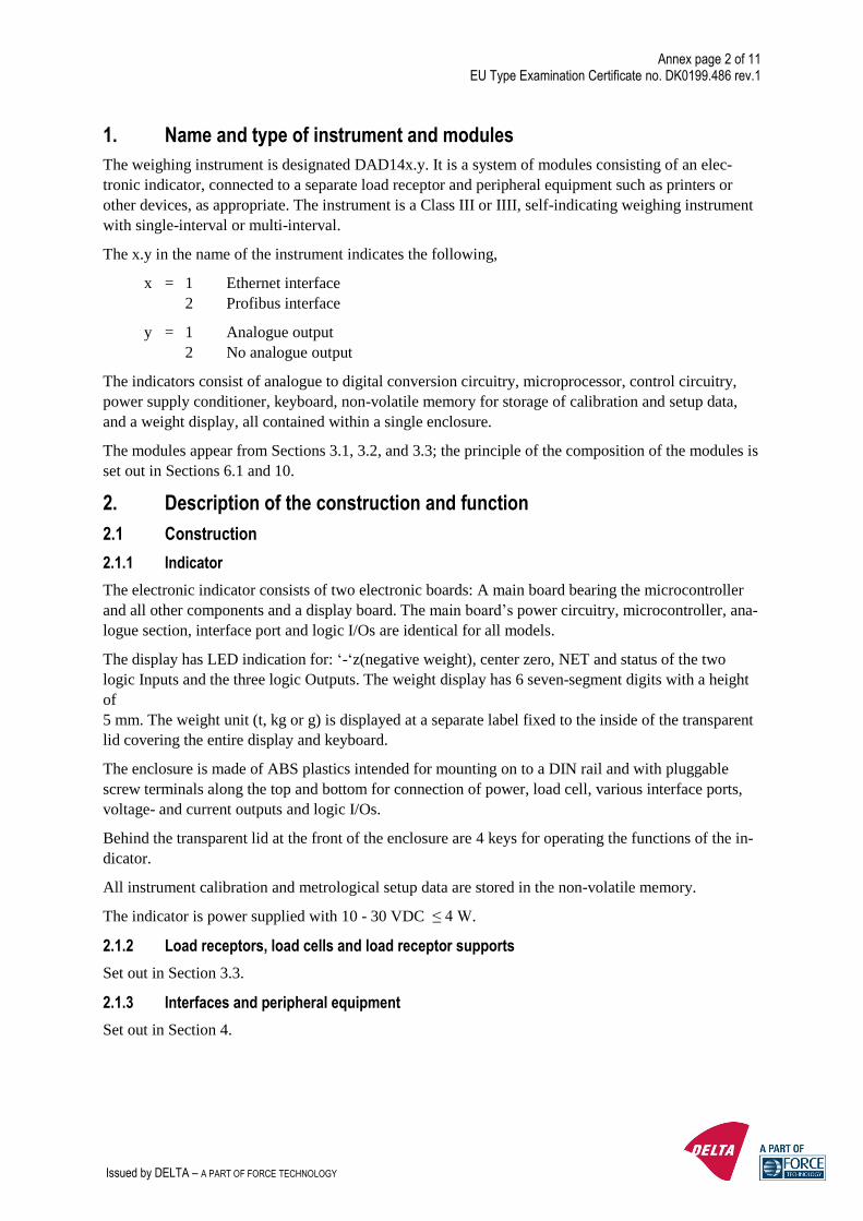
1. Name and type of instrument and modules
The weighing instrument is designated DAD14x.y. It is a system of modules consisting of an elec-
tronic indicator, connected to a separate load receptor and peripheral equipment such as printers or
other devices, as appropriate. The instrument is a Class III or IIII, self-indicating weighing instrument
with single-interval or multi-interval.
The x.y in the name of the instrument indicates the following,
x = 1 Ethernet interface
2 Profibus interface
y = 1 Analogue output
2 No analogue output
The indicators consist of analogue to digital conversion circuitry, microprocessor, control circuitry,
power supply conditioner, keyboard, non-volatile memory for storage of calibration and setup data,
and a weight display, all contained within a single enclosure.
The modules appear from Sections 3.1, 3.2, and 3.3; the principle of the composition of the modules is
set out in Sections 6.1 and 10.
2. Description of the construction and function
2.1 Construction
2.1.1 Indicator
The electronic indicator consists of two electronic boards: A main board bearing the microcontroller
and all other components and a display board. The main board’s power circuitry, microcontroller, ana-
logue section, interface port and logic I/Os are identical for all models.
The display has LED indication for: ‘-‘z(negative weight), center zero, NET and status of the two
logic Inputs and the three logic Outputs. The weight display has 6 seven-segment digits with a height
of
5 mm. The weight unit (t, kg or g) is displayed at a separate label fixed to the inside of the transparent
lid covering the entire display and keyboard.
The enclosure is made of ABS plastics intended for mounting on to a DIN rail and with pluggable
screw terminals along the top and bottom for connection of power, load cell, various interface ports,
voltage- and current outputs and logic I/Os.
Behind the transparent lid at the front of the enclosure are 4 keys for operating the functions of the in-
dicator.
All instrument calibration and metrological setup data are stored in the non-volatile memory.
The indicator is power supplied with 10 - 30 VDC ≤ 4 W.
2.1.2 Load receptors, load cells and load receptor supports
Set out in Section 3.3.
2.1.3 Interfaces and peripheral equipment
Set out in Section 4.

Annex page 3 of 11 EU Type Examination Certificate no. DK0199.486 rev.1
Issued by DELTA – A PART OF FORCE TECHNOLOGY
2.2 Functions
The weight indicating instruments are microcontroller based electronic weight indicators that require
the external connection of (a) strain gauge load cell(s). The weight information appears in the digital
display located on the front section and may be transmitted to peripheral equipment for recording, pro-
cessing or additional displaying. The primary functions provided are detailed below.
2.2.1 Display range
The weight indicators will display weight from –Max to Max (gross weight) within the limits of the
display capacity.
2.2.2 Display test
A self-test routine is initiated at power up. The test routine turns on and off all of the display segments
and indicators to verify that the display is fully functional.
2.2.3 Zero-setting
2.2.3.1 Initial zero-setting
If the selected Zero mode permit initial Zero-setting it will operate within a range of ± 10 % of Max.
Zero-setting is possible only when the load receptor is not in motion.
2.2.3.2 Zero-tracking
If the selected Zero mode permits the zero-tracking feature, it operates over a range of ±2% of Max
and only when the display shows zero (gross or net) and the load receptor is not in motion.
2.2.3.3 Semi-automatic zero-setting
If the selected Zero mode permits semi-automatic zero setting, the following procedure applies: Press-
ing the “ZERO” key causes a new zero reference to be established and turn on ZERO lamp indicating
the display is within the central 1/5th of zero state.
The semi-automatic zero-setting feature operates over a range of ±2 % of Max and only when the load
receptor is not in motion.
2.2.4 Tare
The instrument models are provided with a semi-automatic subtractive tare feature activated using the
“TARE” key. Tare is possible only when the load receptor is not in motion.
2.2.5 Operator information messages
The weight indicator has a number of general and diagnostic messages, which are described in detail
in the User’s Guide.
2.2.6 Software version
The software version is displayed during the start-up of the indicator. (Alternating with the TAC num-
ber). The version format is x.yy, where x is the basic software family, while yy version numbers for
changes and corrections not influencing the legal function of the software.
The approved software version is 1.06.
2.2.7 TAC number
The non-resettable Traceable Access Code is displayed during the start-up of the indicator in the for-
mat: xxxxx. (Alternating with the software version).

Annex page 4 of 11 EU Type Examination Certificate no. DK0199.486 rev.1
Issued by DELTA – A PART OF FORCE TECHNOLOGY
3. Technical data
The DAD14x.y weighing instrument is composed of separate modules, which are set out as follows:
3.1 Indicator
The indicators have the following characteristics:
Type: DAD14x.y
Accuracy class: III or IIII
Weighing range: Single-interval or multi-interval
Maximum number of verification scale intervals (n): 10000 per interval for Class III
1000 per interval for Class IIII
Minimum input voltage per VSI: 0.2 µV
Maximum capacity of interval or range (Max): n × e
Verification scale interval, ei = Max/n
Initial zero-setting range: ± 10 % of Max
Maximum tare effect: 100 % of Max
Fractional factor (pi): 0.5
Excitation voltage: 5 VDC
Circuit for remote sense: Active, (see below)
Minimum input impedance: 58 ohm
Maximum input impedance: 1200 ohm
Connecting cable to load cell(s): See Section 3.1.1
Supply voltage: 10 - 30 VDC, ≤ 4 W.
Operating temperature range: Min/Max = -15 °C/+55 °C
Peripheral interface(s): See Section 4
3.1.1 Connecting cable between the indicator and the load cell or the junction box for load cells
3.1.1.1 4-wire system
Line: 4 wires, shielded
Maximum length: The certified length of the load cell cable, which shall be con-
nected directly to the indicator. (No junction box is allowed).
3.1.1.2 6-wire system
Line: 6 wires, shielded
Option 1:
Maximum length: 2934 m/mm2 (for n = 10,000)
Maximum resistance per wire: 30.2 ohm
In case the (n) for the weighing instrument is less than (n) mentioned above, the following apply:
Option 2:
Coefficient of temperature of the span error of the indicator: Es = 0.0007 [%/25K]
Coefficient of resistance for the wires in the J-box cable: Sx = 0.0014 [%/ohm]
L/Amax = 295.86 / Sx * (emp/n - Es) [m/mm²] in which emp = p'i * mpe * 100/e
From this, the maximum cable length for the weighing instrument may be calculated with regard to (n)
for the actual configuration of the instrument.

Annex page 5 of 11 EU Type Examination Certificate no. DK0199.486 rev.1
Issued by DELTA – A PART OF FORCE TECHNOLOGY
Reference: See section 10.
The calculation program is obtainable by downloading at www.delta.dk/weighing.
3.2 Load receptors, load cells, and load receptor supports
Removable platforms shall be equipped with level indicators.
3.2.1 General acceptance of modules
Any load cell(s) may be used for instruments under this certificate of type approval provided the fol-
lowing conditions are met:
1) An evaluation / part / test certificate (EN 45501) or OIML Certificate of Conformity (R60)
respectively issued for the load cell by a Notified Body responsible for type examination un-
der the Directive 2014/31/EU.
2) The certificate contains the load cell types and the necessary load cell data required for the
manufacturer’s declaration of compatibility of modules (WELMEC 2:2015), and any partic-
ular installation requirements). A load cell marked NH is allowed only if humidity testing to
EN 45501 has been conducted on this load cell.
3) The compatibility of load cells and indicator is established by the manufacturer by means of
the compatibility of modules form, contained in the above WELMEC 2 document, or the
like, at the time of EC verification or declaration of EC conformity of type.
4) The load transmission must conform to one of the examples shown in the WELMEC 2.4
Guide for load cells.
3.2.2 Platforms, weigh bridge platforms
Construction in brief: All-steel or steel-reinforced concrete construction, surface or pit
mounted
Reduction ratio: 1
Junction box: Mounted in or on the platform
Load cells: Load cell according to Section 3.2.1
Drawings: Various
3.2.3 Bin, tank, and hopper
Construction in brief: Load cell assemblies each consisting of a load cell stand assembly to
support one of the mounting feet bin, tank or hopper
Reduction ratio: 1
Junction box: Mounted on dead structure
Load cell: Load cell according to Section 3.2.1
Drawings: Various
3.2.4 Small scale constructions
Construction in brief: Compositions of single point Load cells or Load cell connected with
Beranger or Roberval assemblies to support a scale platform or com-
position of two or four load cells to support a larger platform with or
without a conveyor belt or rollers etc.
Reduction ratio: 1
Junction box (if any) Mounted on dead structure
Load cell: Load cell according to Section 3.2.1
Drawings: Various

Annex page 6 of 11 EU Type Examination Certificate no. DK0199.486 rev.1
Issued by DELTA – A PART OF FORCE TECHNOLOGY
3.3 Composition of modules
In case of composition of modules, EN 45501 paragraph 3.5 and 4.12 shall be satisfied.
3.4 Documents
The documents filed at DELTA (reference No. T206408) are valid for the weighing instruments de-
scribed here.
4. Interfaces and peripheral equipment
4.1 Interfaces
4.1.1 Load cell input
The connector pins for load cell connection are located on the bottom of the enclosure.
4.1.2 Other interfaces
The indicator may in addition to the standard RS485 and Logic inputs/outputs be equipped with one of
following protective interfaces,
• Ethernet
• Profibus
• Modbus RTU
• CAN-open
• Device Net
• Analogue outputs
The interfaces are characterised “Protective interfaces” according to paragraph 8.4 in the Directive and
do not have to be secured.
4.2 Peripheral equipment
Connection between the indicator and peripheral equipment is allowed by a suitable cable.
The instrument may be connected to any simple peripheral device with a CE mark of conformity.
5. Approval conditions
5.1 Measurement functions other than non-automatic functions
Measurement functions that will enable the use of the instrument as an automatic weighing instrument
are not covered by this type approval.
5.2 Compatibility of modules
Composition of modules according to EN 45501:2015 annex F shall be satisfied.
6. Special conditions for verification
6.1 Composition of modules
The environmental conditions should be taken into consideration by the composition of modules for a
complete weighing instrument, for example instruments with load receptors placed outdoors and hav-
ing no special protection against the weather.
The composition of modules shall agree with Section 5.2.
An example of a composition of modules is shown in Section 10.
Annex page 7 of 11 EU Type Examination Certificate no. DK0199.486 rev.1
Issued by DELTA – A PART OF FORCE TECHNOLOGY
7. Securing and location of seals and verification marks
7.1 Securing and sealing
Seals shall bear the verification mark of a notified body or alternative mark of the manufacturer ac-
cording to ANNEX II, module F or D of Directive 2014/31/EU.
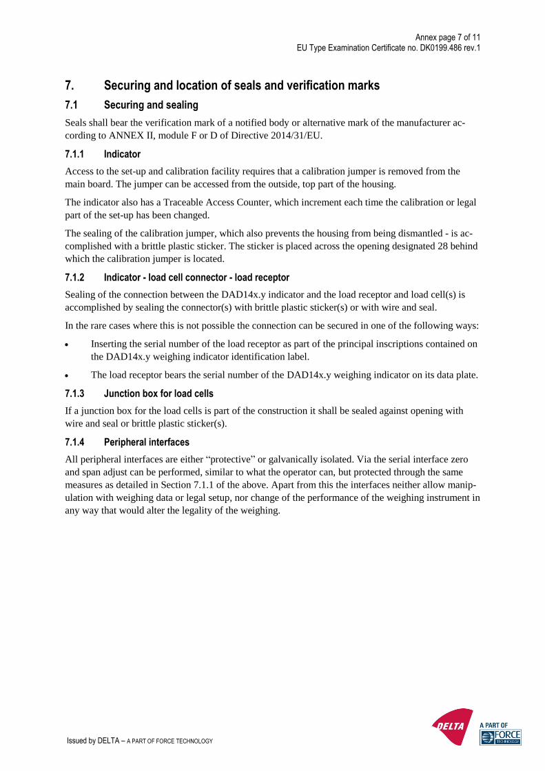
7.1.1 Indicator
Access to the set-up and calibration facility requires that a calibration jumper is removed from the
main board. The jumper can be accessed from the outside, top part of the housing.
The indicator also has a Traceable Access Counter, which increment each time the calibration or legal
part of the set-up has been changed.
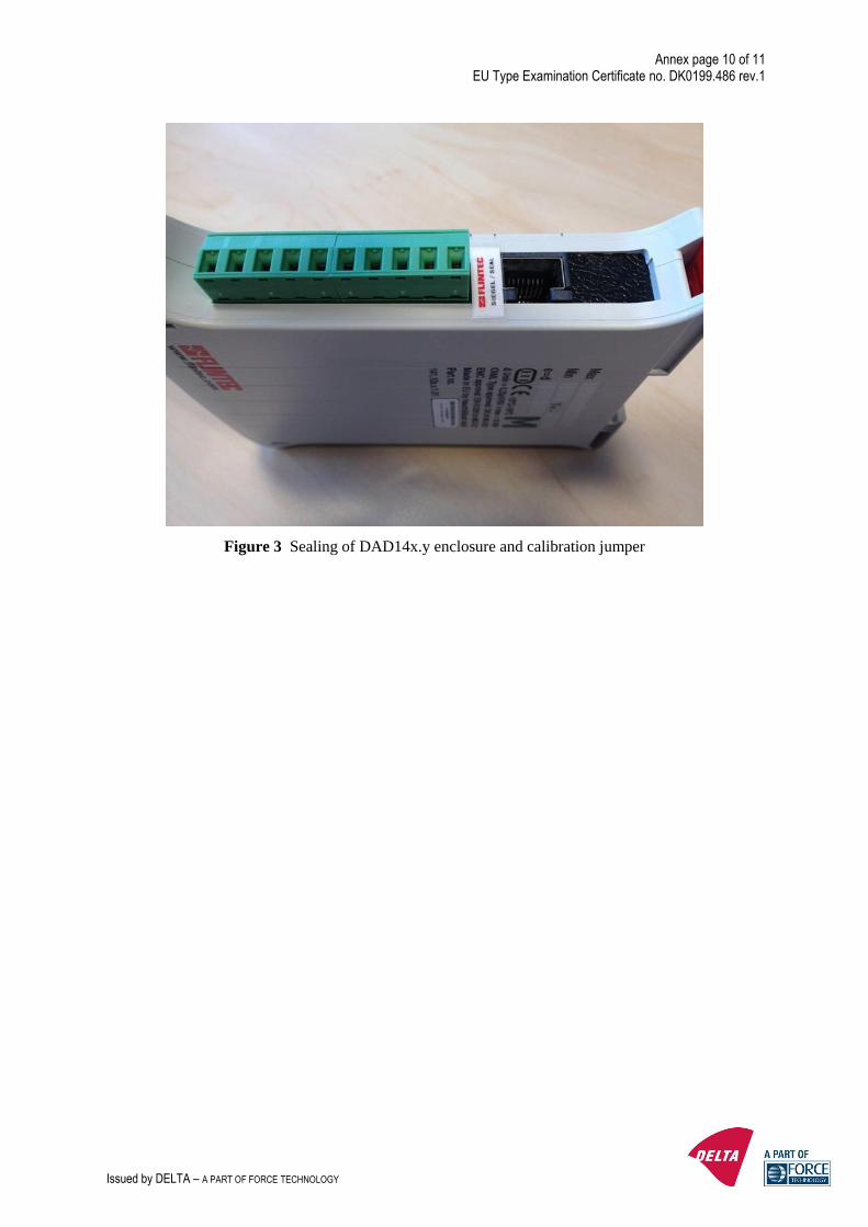
The sealing of the calibration jumper, which also prevents the housing from being dismantled - is ac-
complished with a brittle plastic sticker. The sticker is placed across the opening designated 28 behind
which the calibration jumper is located.
7.1.2 Indicator - load cell connector - load receptor
Sealing of the connection between the DAD14x.y indicator and the load receptor and load cell(s) is
accomplished by sealing the connector(s) with brittle plastic sticker(s) or with wire and seal.
In the rare cases where this is not possible the connection can be secured in one of the following ways:
• Inserting the serial number of the load receptor as part of the principal inscriptions contained on
the DAD14x.y weighing indicator identification label.
• The load receptor bears the serial number of the DAD14x.y weighing indicator on its data plate.
7.1.3 Junction box for load cells
If a junction box for the load cells is part of the construction it shall be sealed against opening with
wire and seal or brittle plastic sticker(s).
7.1.4 Peripheral interfaces
All peripheral interfaces are either “protective” or galvanically isolated. Via the serial interface zero
and span adjust can be performed, similar to what the operator can, but protected through the same
measures as detailed in Section 7.1.1 of the above. Apart from this the interfaces neither allow manip-
ulation with weighing data or legal setup, nor change of the performance of the weighing instrument in
any way that would alter the legality of the weighing.
Annex page 8 of 11 EU Type Examination Certificate no. DK0199.486 rev.1
Issued by DELTA – A PART OF FORCE TECHNOLOGY
8. Location of CE mark of conformity and inscriptions
8.1 Indicator
8.1.1 CE mark
CE mark and supplementary metrological marking shall be applied to the scale according to article 16
of Directive 2014/31/EU.
8.1.2 Inscriptions
The following details are found at the identification section, which is printed directly at the enclosure
or at a label placed at the enclosure of the weight indicator:
• Max, Min, e =
• Manufacturer’s name, postal address of manufacturer, model no., serial no., type-approval certifi-
cate no. and accuracy class.
Additional information such as serial no. of the load receptor or various trademarks are printed sepa-
rately or found at separate label(s).
8.1.2.1 Load receptors
On a data plate:
• Manufacturer's name, type, serial number, capacity
• Serial no. of the indicator

Annex page 9 of 11 EU Type Examination Certificate no. DK0199.486 rev.1
Issued by DELTA – A PART OF FORCE TECHNOLOGY
9. Pictures
Figure 1 DAD141.1 indicator.
Figure 2 2 DAD14x.y indicators seen from front.
Annex page 10 of 11 EU Type Examination Certificate no. DK0199.486 rev.1
Issued by DELTA – A PART OF FORCE TECHNOLOGY
Figure 3 Sealing of DAD14x.y enclosure and calibration jumper

Annex page 11 of 11 EU Type Examination Certificate no. DK0199.486 rev.1
Issued by DELTA – A PART OF FORCE TECHNOLOGY
10. Composition of modules - example