EU contract number RII3-CT-2003-506395 CARE/ELAN … · Beam envelope along the lattice Thus, beam...
25
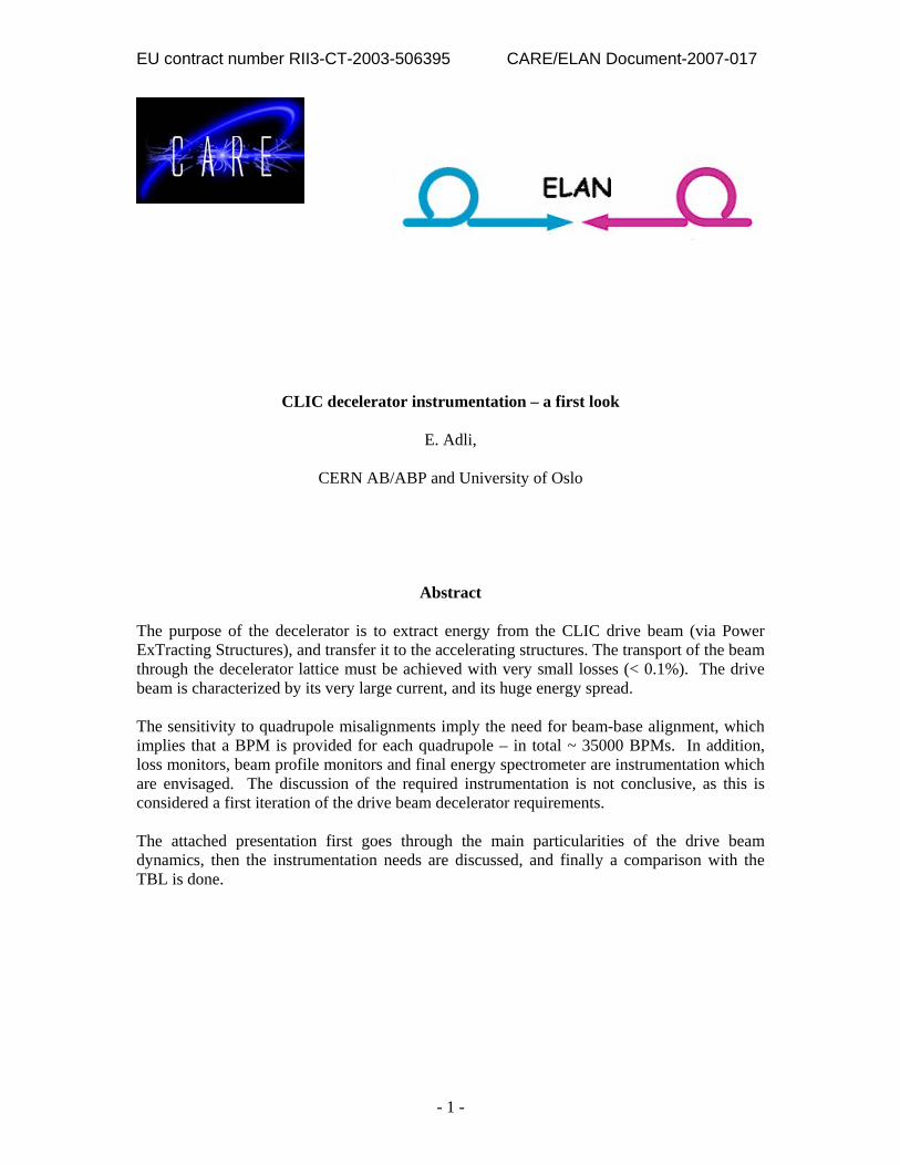
EU contract number RII3-CT-2003-506395 CARE/ELAN Document-2007-017 - 1 - CLIC decelerator instrumentation – a first look E. Adli, CERN AB/ABP and University of Oslo Abstract The purpose of the decelerator is to extract energy from the CLIC drive beam (via Power ExTracting Structures), and transfer it to the accelerating structures. The transport of the beam through the decelerator lattice must be achieved with very small losses (< 0.1%). The drive beam is characterized by its very large current, and its huge energy spread. The sensitivity to quadrupole misalignments imply the need for beam-base alignment, which implies that a BPM is provided for each quadrupole – in total ~ 35000 BPMs. In addition, loss monitors, beam profile monitors and final energy spectrometer are instrumentation which are envisaged. The discussion of the required instrumentation is not conclusive, as this is considered a first iteration of the drive beam decelerator requirements. The attached presentation first goes through the main particularities of the drive beam dynamics, then the instrumentation needs are discussed, and finally a comparison with the TBL is done.
Transcript of EU contract number RII3-CT-2003-506395 CARE/ELAN … · Beam envelope along the lattice Thus, beam...
EU contract number RII3-CT-2003-506395 CARE/ELAN Document-2007-017
- 1 -
CLIC decelerator instrumentation – a first look
E. Adli,
CERN AB/ABP and University of Oslo
Abstract
The purpose of the decelerator is to extract energy from the CLIC drive beam (via Power ExTracting Structures), and transfer it to the accelerating structures. The transport of the beam through the decelerator lattice must be achieved with very small losses (< 0.1%). The drive beam is characterized by its very large current, and its huge energy spread. The sensitivity to quadrupole misalignments imply the need for beam-base alignment, which implies that a BPM is provided for each quadrupole – in total ~ 35000 BPMs. In addition, loss monitors, beam profile monitors and final energy spectrometer are instrumentation which are envisaged. The discussion of the required instrumentation is not conclusive, as this is considered a first iteration of the drive beam decelerator requirements. The attached presentation first goes through the main particularities of the drive beam dynamics, then the instrumentation needs are discussed, and finally a comparison with the TBL is done.

EU contract number RII3-CT-2003-506395 CARE/ELAN Document-200X-YYY
- 2 -
Acknowledgements We acknowledge the support of the European Community-Research Infrastructure Activity under the FP6 “Structuring the European Research Area” programme (CARE, contract number RII3-CT-2003-506395)

The CLIC decelerator The CLIC decelerator Instrumentation issues Instrumentation issues –– a first looka first look
E. Adli, CERN AB/ABP / UiOE. Adli, CERN AB/ABP / UiOOctober 17, 2007October 17, 2007
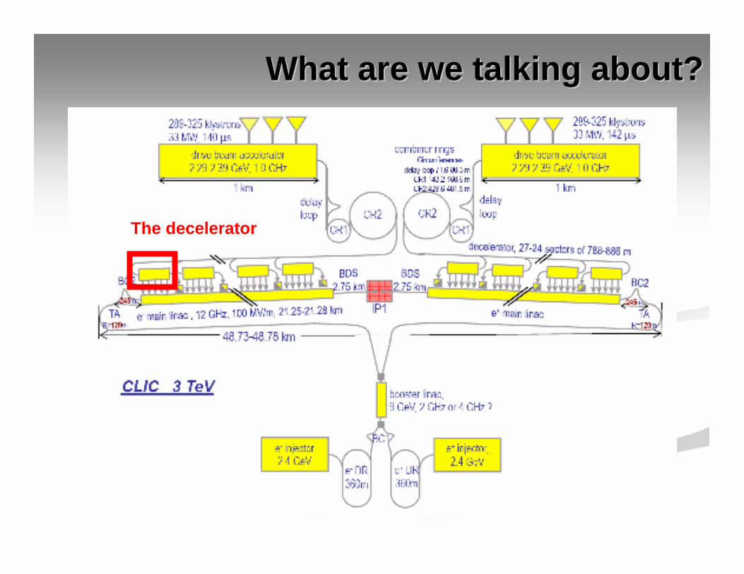
What are we talking about?What are we talking about?
The decelerator

ContentContent
Particularities of the decelerator beamParticularities of the decelerator beam
Instrumentation discussionInstrumentation discussion
Comparison with the TBLComparison with the TBL
Goal of presentation: convey beam dynamics of the drive beam decelerator, then discuss (in plenum) the instrumentation issues

Part 1Part 1
Particularities of the decelerator beamParticularities of the decelerator beam

Decelerator BD requirementsDecelerator BD requirementsDeliver required power to accelerating structuresDeliver required power to accelerating structures→→ Minimize losses ( smaller than 0.1% )Minimize losses ( smaller than 0.1% )
High power production efficiencyHigh power production efficiency→→ Low final energy Low final energy →→ large energy spreadlarge energy spread
Our target is to transport the beam, the Our target is to transport the beam, the whole whole beambeam, through the decelerator lattice, through the decelerator lattice
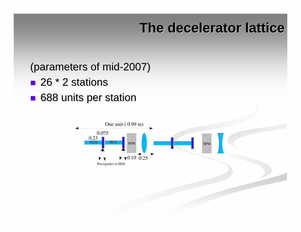
The decelerator latticeThe decelerator lattice
(parameters of mid(parameters of mid--2007)2007)26 * 2 stations26 * 2 stations688 units per station688 units per station

The CLIC drive beamThe CLIC drive beamHighHigh--current, lowcurrent, low--energy beam for strong wake field generationenergy beam for strong wake field generation
Initial beam parameters:Initial beam parameters:EE0 0 ≈≈ 2.5 2.5 GeVGeVI I ≈≈ 96 A96 Ad = 25 mm (bunch spacing, fd = 25 mm (bunch spacing, fbb = 12 GHz)= 12 GHz)τ τ ≈≈ 300 ns (3564 bunches) 300 ns (3564 bunches) Gaussian bunch, Gaussian bunch, σσz z ≈≈ 1 mm1 mmεεΝΝ ≈≈ 150 μ150 μm m
11stst particularity of the decelerator beam: huge currentparticularity of the decelerator beam: huge current

Principle of power generationPrinciple of power generationParticles will feel parasitic loss and induce a wake field in Particles will feel parasitic loss and induce a wake field in the PETSthe PETSThe wake field will interact with and further decelerate :The wake field will interact with and further decelerate :
1) rear part of bunch (1) rear part of bunch (singlesingle--bunchbunch effect)effect)2) following bunches (2) following bunches (multimulti--bunchbunch effect)effect)
The integrated effect in a PETS on a witness particle due The integrated effect in a PETS on a witness particle due to a source particle is given byto a source particle is given by

Simulation results: energy extractionSimulation results: energy extraction
PETS longitudinal wake parameters:PETS longitudinal wake parameters:RR’’/Q = 2295 /Q = 2295 ΩΩ/m (linac/m (linac--convention)convention)ffLL=11.99 GHz=11.99 GHzββgg = 0.453= 0.453
Beam energy profile after lattice: Beam energy profile after lattice: (initial: flat E(initial: flat E00=2.5 GeV)=2.5 GeV)
22ndnd particularity of the decelerator: huge energy spread particularity of the decelerator: huge energy spread
0
0.5
1
1.5
2
2.5
-0.2 0 0.2 0.4 0.6 0.8 1 1.2 1.4
E [G
eV]
s [m]
Energy distribution of the beam
0
0.5
1
1.5
2
2.5
-0.2 0 0.2 0.4 0.6 0.8 1 1.2 1.4
E [G
eV]
s [m]
Energy distribution of the beam
0
0.5
1
1.5
2
2.5
-0.05 0 0.05 0.1 0.15 0.2 0.25 0.3
E [G
eV]
s [m]
Energy distribution of the beam
0
0.5
1
1.5
2
2.5
-0.05 0 0.05 0.1 0.15 0.2 0.25 0.3
E [G
eV]
s [m]
Energy distribution of the beam
NB: leading particle always to the left! (PLACET output def.)NB: leading particle always to the left! (PLACET output def.)

Energy extraction efficiency: Energy extraction efficiency: ηηη=η=PPinin/P/Poutout : : steady statesteady state power extraction eff.: power extraction eff.: η=η=P[W]P[W]××N / E0[eV]N / E0[eV]××I[A] I[A]
We can express the We can express the steady statesteady state extraction efficiency as:extraction efficiency as:η η = S = S ×× F(F(σσ) ) ×× ηηdistdist
where for current CLIC parameters:where for current CLIC parameters:S = 90.0 % (max energy spread)S = 90.0 % (max energy spread)η η = S = S ×× F(F(σσ) ) ×× ηηdistdist = 90.0 % = 90.0 % ×× 96.9 %96.9 % ×× 97.4 %97.4 % ==84.5 %84.5 %
((ηηdistdist can be improved with detuning: not discussed further here)can be improved with detuning: not discussed further here)
0.2
0.3
0.4
0.5
0.6
0.7
0.8
0.9
1
1.1
-3000 -2000 -1000 0 1000 2000 3000
E [G
eV]
relative pos [um]
Energy distribution of a bunch (steady-state)
WeigthEnergy
0.2
0.3
0.4
0.5
0.6
0.7
0.8
0.9
1
1.1
-3000 -2000 -1000 0 1000 2000 3000
E [G
eV]
relative pos [um]
Energy distribution of a bunch (steady-state)
WeigthEnergy

Energy spread and beam envelopeEnergy spread and beam envelopeWhy is the max. energy spread, S, important?Why is the max. energy spread, S, important?In the TBL we will have the effect of In the TBL we will have the effect of adiabatic adiabatic undampingundamping
(fig: A. Chao)(fig: A. Chao)
The divergence, yThe divergence, y’’=dy/ds, and ultimately also beam =dy/ds, and ultimately also beam envelope, will increase with decreasing energyenvelope, will increase with decreasing energy

Beam envelope along the latticeBeam envelope along the latticeThus, beam envelope along the lattice rThus, beam envelope along the lattice radad ∝∝ 1/1/√√γγ
1
1.5
2
2.5
3
3.5
0 100 200 300 400 500 600 700
3-si
gma
beam
env
elop
e [m
m]
s [m]
Beam envelope along the lattice
1
1.5
2
2.5
3
3.5
0 100 200 300 400 500 600 700
3-si
gma
beam
env
elop
e [m
m]
s [m]
Beam envelope along the lattice
0.2
0.3
0.4
0.5
0.6
0.7
0.8
0.9
1
1.1
-3000 -2000 -1000 0 1000 2000 3000
E [G
eV]
relative pos [um]
Energy distribution of a bunch (steady-state)
WeigthEnergy
0.2
0.3
0.4
0.5
0.6
0.7
0.8
0.9
1
1.1
-3000 -2000 -1000 0 1000 2000 3000
E [G
eV]
relative pos [um]
Energy distribution of a bunch (steady-state)
WeigthEnergy
02/2222 )1/(2333 γεσσ SLr NFODOyxad −⋅≈+=
Beam envelope due to adiabatic undamping aloneBeam envelope due to adiabatic undamping alone

Misalignment: PETSMisalignment: PETS
Misalignment and beam jitter will introduce growth of Misalignment and beam jitter will introduce growth of beam envelope due to transverse wakesbeam envelope due to transverse wakesEffect on beam envelope for PETS misalignment of 200 Effect on beam envelope for PETS misalignment of 200 um:um:
1
1.5
2
2.5
3
3.5
4
4.5
0 100 200 300 400 500 600 700
3-si
gma
beam
env
elop
e [m
m]
s [m]
Beam envelope along the lattice
NC
1
1.5
2
2.5
3
3.5
4
4.5
0 100 200 300 400 500 600 700
3-si
gma
beam
env
elop
e [m
m]
s [m]
Beam envelope along the lattice
NC
1
1.5
2
2.5
3
3.5
0 100 200 300 400 500 600 700
3-si
gma
beam
env
elop
e [m
m]
s [m]
Beam envelope along the lattice
1
1.5
2
2.5
3
3.5
0 100 200 300 400 500 600 700
3-si
gma
beam
env
elop
e [m
m]
s [m]
Beam envelope along the lattice
Adiabatic effects alone
With PETS misalignment

Misalignment: quadsMisalignment: quads
Misalignment of quadruples will introduce growth of beam Misalignment of quadruples will introduce growth of beam envelope due to kicksenvelope due to kicksEffect on beam envelope for quadrupole misalignment of Effect on beam envelope for quadrupole misalignment of 20 um:20 um:
1
1.5
2
2.5
3
3.5
0 100 200 300 400 500 600 700
3-si
gma
beam
env
elop
e [m
m]
s [m]
Beam envelope along the lattice
1
1.5
2
2.5
3
3.5
0 100 200 300 400 500 600 700
3-si
gma
beam
env
elop
e [m
m]
s [m]
Beam envelope along the lattice
0
2
4
6
8
10
12
14
0 100 200 300 400 500 600 700
3-si
gma
beam
env
elop
e [m
m]
s [m]
Beam envelope along the lattice
NC
0
2
4
6
8
10
12
14
0 100 200 300 400 500 600 700
3-si
gma
beam
env
elop
e [m
m]
s [m]
Beam envelope along the lattice
NC
33rdrd particularity of the decelerator: large beam sizeparticularity of the decelerator: large beam size
Adiabatic effects alone
With quadrupole misalignment

BeamBeam--based alignmentbased alignment
Predicted prePredicted pre--alignment accuracy of quads is not alignment accuracy of quads is not acceptable for operationacceptable for operationBeamBeam--based alignment requiredbased alignment requiredForeseen methodsForeseen methods
11--toto--1 steering (for initial correction)1 steering (for initial correction)Dispersion Free SteeringDispersion Free Steering
Both methods require one BPMs for each quadrupoleBoth methods require one BPMs for each quadrupole
0
2
4
6
8
10
12
14
0 100 200 300 400 500 600 700
3-si
gma
beam
env
elop
e [m
m]
s [m]
Beam envelope along the lattice
NCDSF
0
2
4
6
8
10
12
14
0 100 200 300 400 500 600 700
3-si
gma
beam
env
elop
e [m
m]
s [m]
Beam envelope along the lattice
NCDSF
0.1 0.2 0.3 0.4 0.5 0.6 0.7 0.8 0.9
1 1.1 1.2
2 4 6 8 10 12 14 16 18
Cen
troi
d en
velo
pe [m
m]
BPM resolution [um] sigma
Max centroid envelope, BPM resolution
DFS
0.1 0.2 0.3 0.4 0.5 0.6 0.7 0.8 0.9
1 1.1 1.2
2 4 6 8 10 12 14 16 18
Cen
troi
d en
velo
pe [m
m]
BPM resolution [um] sigma
Max centroid envelope, BPM resolution
DFS
Part 2Part 2
Decelerator instrumentation Decelerator instrumentation –– a first looka first look
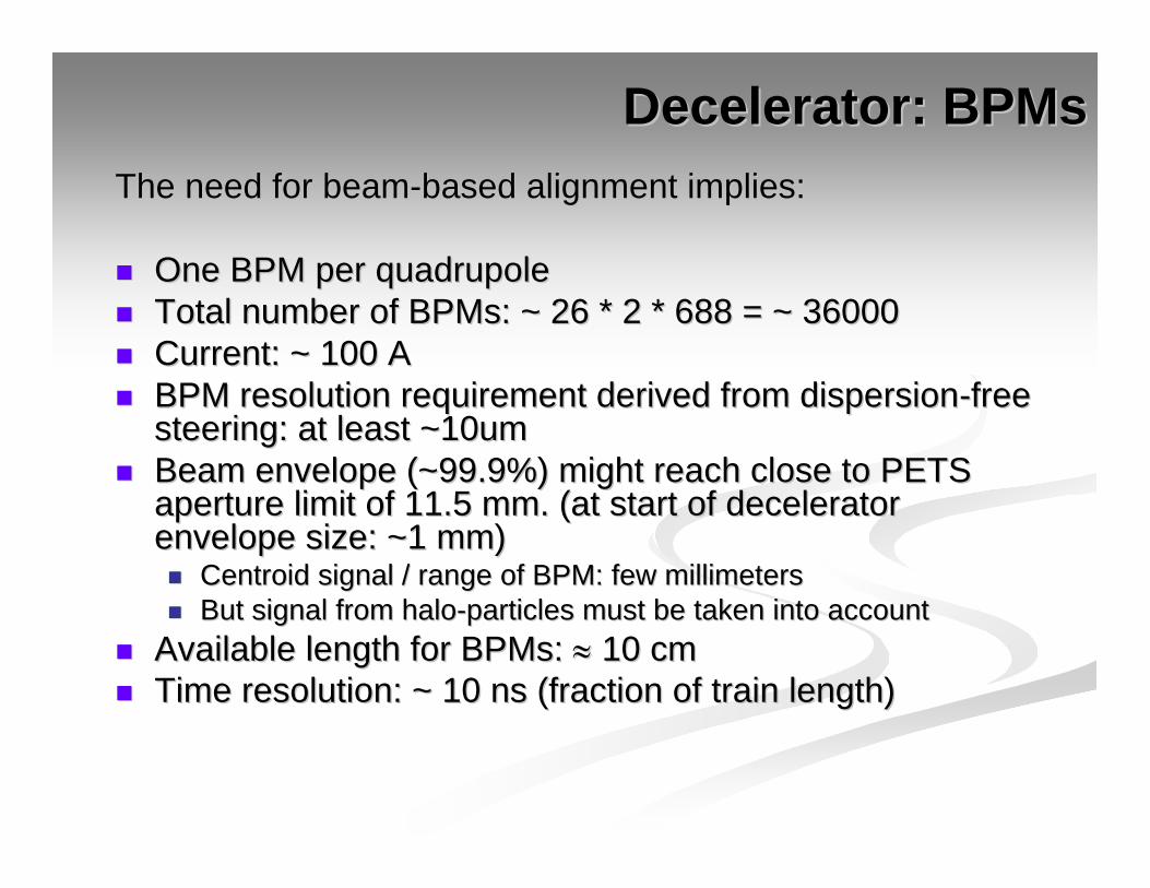
Decelerator: Decelerator: BPMsBPMsThe need for beamThe need for beam--based alignment implies:based alignment implies:
One BPM per quadrupoleOne BPM per quadrupoleTotal number of Total number of BPMsBPMs: ~ 26 * 2 * 688 = ~ 36000: ~ 26 * 2 * 688 = ~ 36000Current: ~ 100 ACurrent: ~ 100 ABPM resolution requirement derived from dispersionBPM resolution requirement derived from dispersion--free free steering: at least ~10umsteering: at least ~10umBeam envelope (~99.9%) might reach close to PETS Beam envelope (~99.9%) might reach close to PETS aperture limit of 11.5 mm. (at start of decelerator aperture limit of 11.5 mm. (at start of decelerator envelope size: ~1 mm)envelope size: ~1 mm)
CentroidCentroid signal / range of BPM: few millimeterssignal / range of BPM: few millimetersBut signal from haloBut signal from halo--particles must be taken into accountparticles must be taken into account
Available length for BPMs: Available length for BPMs: ≈≈ 10 cm10 cmTime resolution: ~ 10 ns (fraction of train length)Time resolution: ~ 10 ns (fraction of train length)

Decelerator: loss monitorsDecelerator: loss monitorsRequired: loss monitorsRequired: loss monitors
Ensuring beam transport with minimal losses is Ensuring beam transport with minimal losses is crucialcrucialInstallation frequency of these components is TBDInstallation frequency of these components is TBDKeeping instrumentation small is of concern (in the Keeping instrumentation small is of concern (in the current design: zero length is foreseen for such current design: zero length is foreseen for such instrumentation, except of PETSinstrumentation, except of PETS--free units)free units)
Desirable: instrumentation to measure Desirable: instrumentation to measure transverse beam size (frequency of these transverse beam size (frequency of these components TBD)components TBD)

Decelerator: other instrumentationDecelerator: other instrumentationMeasurement of beam energy at the end of the lattice (Measurement of beam energy at the end of the lattice (spectometerspectometer/ / dumpdump--measurement)measurement)
PhasePhase--monitors for synchronization drive beam and main beammonitors for synchronization drive beam and main beam
Entrance (feedback to BC) and possibly exit: bunch length/long. Entrance (feedback to BC) and possibly exit: bunch length/long. emittanceemittance measurementmeasurement
0.2
0.3
0.4
0.5
0.6
0.7
0.8
0.9
1
1.1
-3000 -2000 -1000 0 1000 2000 3000
E [G
eV]
relative pos [um]
Energy distribution of a bunch (steady-state)
WeigthEnergy
0.2
0.3
0.4
0.5
0.6
0.7
0.8
0.9
1
1.1
-3000 -2000 -1000 0 1000 2000 3000
E [G
eV]
relative pos [um]
Energy distribution of a bunch (steady-state)
WeigthEnergy
Part 3Part 3
The Test Beam LineThe Test Beam Line

TBL: the test of the deceleratorTBL: the test of the decelerator
Lattice:
16 units of one of each:
• PETS + coupler
• Quad
• BPM
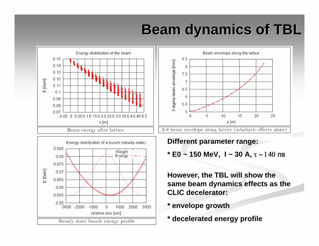
Beam dynamics of TBLBeam dynamics of TBL
However, the TBL will show the same beam dynamics effects as the CLIC decelerator:
* envelope growth
* decelerated energy profile
Different parameter range:
* E0 ~ 150 MeV, I ~ 30 A, τ ∼ 140 ns

Instrumentation for the TBLInstrumentation for the TBLBPMs: one per quad, resolution ~ 10 um and BPMs: one per quad, resolution ~ 10 um and dynamic range of up to ~ PETS aperture limit (?)dynamic range of up to ~ PETS aperture limit (?)
Spectrometer: here good energy measurement Spectrometer: here good energy measurement at end of lattice is very important (benchmarking at end of lattice is very important (benchmarking of model and code)of model and code)
...with z...with z--dependence? Ideas?dependence? Ideas?
Profile / loss monitorsProfile / loss monitorsbeam size at end of lattice?beam size at end of lattice?