ETSI TS 103 344 V0.0 · PDF fileETSI TS 103 344 V0.0.22 (2016-06) ... i.e. on signaling...
88
ETSI TS 103 344 V0.0.22 (2016-06) Core Network and Interoperability Testing (INT); Small Cell LTE Interoperability Test Specification TECHNICAL SPECIFICATION
Transcript of ETSI TS 103 344 V0.0 · PDF fileETSI TS 103 344 V0.0.22 (2016-06) ... i.e. on signaling...

ETSI TS 103 344 V0.0.22 (2016-06)
Core Network and Interoperability Testing (INT); Small Cell LTE Interoperability Test Specification
TECHNICAL SPECIFICATION

ETSI
ETSI TS 103 344 V0.0.22 (2016-06) 2 [Release 10]
Reference
DTS/INT-00126
Keywords
interoperability, testing
ETSI
650 Route des Lucioles
F-06921 Sophia Antipolis Cedex - FRANCE
Tel.: +33 4 92 94 42 00 Fax: +33 4 93 65 47 16
Siret N° 348 623 562 00017 - NAF 742 C
Association à but non lucratif enregistrée à la
Sous-préfecture de Grasse (06) N° 7803/88
Important notice
The present document can be downloaded from:
http://www.etsi.org
The present document may be made available in electronic versions and/or in print. The content of any electronic and/or
print versions of the present document shall not be modified without the prior written authorization of ETSI. In case of any
existing or perceived difference in contents between such versions and/or in print, the only prevailing document is the
print of the Portable Document Format (PDF) version kept on a specific network drive within ETSI Secretariat.
Users of the present document should be aware that the document may be subject to revision or change of status.
Information on the current status of this and other ETSI documents is available at
http://portal.etsi.org/tb/status/status.asp
If you find errors in the present document, please send your comment to one of the following services:
http://portal.etsi.org/chaircor/ETSI_support.asp
Copyright Notification
No part may be reproduced or utilized in any form or by any means, electronic or mechanical, including photocopying
and microfilm except as authorized by written permission of ETSI.
The content of the PDF version shall not be modified without the written authorization of ETSI.
The copyright and the foregoing restriction extend to reproduction in all media.
© European Telecommunications Standards Institute yyyy.
All rights reserved.
DECTTM, PLUGTESTSTM, UMTSTM and the ETSI logo are Trade Marks of ETSI registered for the benefit of its Members.
3GPPTM and LTE™ are Trade Marks of ETSI registered for the benefit of its Members and
of the 3GPP Organizational Partners.
GSM® and the GSM logo are Trade Marks registered and owned by the GSM Association.
ETSI
ETSI TS 103 344 V0.0.22 (2016-06) 3 [Release 10]
Contents
Contents .............................................................................................................................................................. 3
Intellectual Property Rights ................................................................................................................................ 4
Foreword............................................................................................................................................................. 4
Modal verbs terminology ................................................................................................................................... 5
1 Scope ........................................................................................................................................................ 6
2 References ................................................................................................................................................ 6 2.1 Normative references ......................................................................................................................................... 6 2.2 Informative references ....................................................................................................................................... 7
3 Abbreviations ........................................................................................................................................... 7
4 Conventions .............................................................................................................................................. 7 4.1 The test description proforma ............................................................................................................................ 7 4.2 Interoperable Feature Statement ........................................................................................................................ 8
5 Configurations .......................................................................................................................................... 8 5.1 CFG_eNB .......................................................................................................................................................... 8 5.2 CFG_HeNB ....................................................................................................................................................... 9 5.3 CFG_(H)eNB ..................................................................................................................................................... 9 5.4 CFG_LIPA ......................................................................................................................................................... 9 5.5 CFG_CMAS .................................................................................................................................................... 10 5.6 CFG_IMS ........................................................................................................................................................ 10 5.7 CFG_S1_MOB ................................................................................................................................................ 10 5.8 CFG_S1_MOB_LOCAL ................................................................................................................................. 11 5.9 CFG_X2 ........................................................................................................................................................... 11
6 Interoperable Feature Statement (IFS) ................................................................................................... 12
7 Test Descriptions .................................................................................................................................... 13 7.1 Test Groups ...................................................................................................................................................... 13 7.1.1 Regression .................................................................................................................................................. 13 7.1.1.1 Regression eNB .................................................................................................................................... 13 7.1.1.2 Regression HeNB ................................................................................................................................. 13 7.1.1.3 Regression Common............................................................................................................................. 13 7.1.1.4 CMAS ................................................................................................................................................... 14 7.1.2 Local IP Access Group (LIPA) .................................................................................................................. 14 7.1.3 Closed Subscriber Group (CSG) ................................................................................................................ 14 7.1.4 IMS............................................................................................................................................................. 14 7.1.5 Mobility (MOB) ......................................................................................................................................... 15 7.1.5.1 X2 Mobility .......................................................................................................................................... 15 7.1.5.2 S1 Mobility ........................................................................................................................................... 15 7.2 Regression Tests .............................................................................................................................................. 15 7.2.1 REG/ENB/01 – eNB Registration with EPC - Success .............................................................................. 15 7.2.2 REG/ENB/02 – eNB Registration with EPC – Failure .............................................................................. 16 7.2.3 REG/HENB/01 – HeNB-GW Registration with EPC - Success ................................................................ 17 7.2.4 REG/HENB/02 – HeNB Registration with HeNB-GW (pre-registered TAC) – Success .......................... 18 7.2.5 REG/HENB/03 – HeNB Registration with HeNB-GW (not pre-registered TAC) - Success (optional) .... 19 7.2.6 REG/HENB/04 – Registration with HeNB-GW (not pre-registered TAC) – Failure (optional) ................ 21

ETSI
ETSI TS 103 344 V0.0.22 (2016-06) 4 [Release 10]
7.2.7 REG/HENB/05 - HeNB Registration with HeNB-GW (unknown PLMN) – Failure ................................ 21 7.2.8 REG/UE/01 - UE Registration / Default Bearer Setup / Downlink-Uplink Traffic Flow .......................... 22 7.2.9 REG/UE/02 - UE Deregistration / Network Detach ................................................................................... 25 7.2.10 PS/01 - Paging ............................................................................................................................................ 26 7.2.11 PS/03 - Network initiated E-RAB setup – Distinct Bearer (optional) ........................................................ 28 7.2.12 PS/04 - Network initiated E-RAB setup – Combined Bearer (optional) .................................................... 30 7.2.13 PS/05 - Network initiated E-RAB release .................................................................................................. 31 7.2.14 PS/06 – E-RAB modification by the network ............................................................................................ 33 7.2.15 CMAS/01 - CMAS Warning Start to List of (H)eNBs .............................................................................. 35 7.2.16 CMAS/02 - CMAS Warning Start to TAI List .......................................................................................... 37 7.2.17 CMAS/03 - CMAS Warning Stop to List of HeNBs ................................................................................. 39 7.2.18 CMAS/04 - CMAS Warning Stop to TAI List ........................................................................................... 41 7.3 Test Description for Small Cell LTE Remote Plugfest 2015 ........................................................................... 43 7.3.1 LIPA/01 - Downlink Traffic Flow through L-GW ..................................................................................... 43 7.3.2 CSG/01 – UE Registration with CSG (H)eNB ........................................................................................... 44 7.3.3 CSG/02 – UE is no longer allowed to access the CSG cell ........................................................................ 46 7.3.4 CSG/03 – Manual CSG selection – allowed UE ........................................................................................ 47 7.3.5 CSG/04 – Manual CSG selection – not allowed UE .................................................................................. 50 7.3.6 CSG/05 - UE Registration with hybrid (H)eNB ......................................................................................... 51 7.3.7 IMS/01 – UE SIP Registration ................................................................................................................... 53 7.3.9 IMS/02 – UE SIP Originating Call (VoLTE) ............................................................................................. 57 7.3.10 IMS/03 – UE SIP Terminating Call (VoLTE) ........................................................................................... 58 7.3.11 IMS/04 – UE Originating Video Call ......................................................................................................... 60 7.3.12 IMS/05 – UE Terminating Video Call ....................................................................................................... 62 7.3.13 MOB/X2/01 – X2 Setup ............................................................................................................................. 64 7.3.14 MOB/X2/02 – X2 based Handover ............................................................................................................ 68 7.3.15 MOB/X2/03 – X2 Reset ............................................................................................................................. 70 7.3.16 MOB/X2/04 – X2 Load Indication ............................................................................................................ 71 7.3.17 MOB/S1/01 – S1 based Handover ............................................................................................................. 72 7.3.18 MOB/S1/02 – Local S1 based Handover ................................................................................................... 73
Annex A (informative): Standardized QCI characteristics ............................................................................... 84
Annex B (informative): Mapping of test description identifiers ...................................................................... 86
History .............................................................................................................................................................. 87
Intellectual Property Rights
IPRs essential or potentially essential to the present document may have been declared to ETSI. The information
pertaining to these essential IPRs, if any, is publicly available for ETSI members and non-members, and can be found
in ETSI SR 000 314: "Intellectual Property Rights (IPRs); Essential, or potentially Essential, IPRs notified to ETSI in
respect of ETSI standards", which is available from the ETSI Secretariat. Latest updates are available on the ETSI Web
server (http://ipr.etsi.org).
Pursuant to the ETSI IPR Policy, no investigation, including IPR searches, has been carried out by ETSI. No guarantee
can be given as to the existence of other IPRs not referenced in ETSI SR 000 314 (or the updates on the ETSI Web
server) which are, or may be, or may become, essential to the present document.
Foreword
This Technical Specification (TS) has been produced by ETSI Technical Committee Core Network and Interoperability
Testing (INT).

ETSI
ETSI TS 103 344 V0.0.22 (2016-06) 5 [Release 10]
Modal verbs terminology
In the present document "shall", "shall not", "should", "should not", "may", "may not", "need", "need not", "will",
"will not", "can" and "cannot" are to be interpreted as described in clause 3.2 of the ETSI Drafting Rules (Verbal forms
for the expression of provisions).
"must" and "must not" are NOT allowed in ETSI deliverables except when used in direct citation.

ETSI
ETSI TS 103 344 V0.0.22 (2016-06) 6 [Release 10]
1 Scope
The present document represents an interoperability test specification with the purpose of supporting the Small Cell
LTE Remote Plugfest 2016 by covering the following features:
Regression testing (Registration, setup, data transfer, CMAS)
Carrier Aggregation
LIPA and SIPTO
VoLTE
Closed Subscriber Group
The main focus is on Small Cell-LTE interoperability, i.e. on signaling messages over the S1 interface.
2 References
References are either specific (identified by date of publication and/or edition number or version number) or
non-specific. For specific references, only the cited version applies. For non-specific references, the latest version of the
reference document (including any amendments) applies.
Referenced documents which are not found to be publicly available in the expected location might be found at
http://docbox.etsi.org/Reference.
NOTE: While any hyperlinks included in this clause were valid at the time of publication, ETSI cannot guarantee
their long term validity.
2.1 Normative references
The following referenced documents are necessary for the application of the present document.
[1] 3GPP TS 22.220 10.10.0: "3rd Generation Partnership Project; Technical Specification Group
Services and System Aspects; Service requirements for Home Node B (HNB) and Home eNode B
(HeNB) (Release 10)".
[2] 3GPP TS 23.401 10.13.0: "3rd Generation Partnership Project; Technical Specification Group
Services and System Aspects; General Packet Radio Service (GPRS) enhancements for Evolved
Universal Terrestrial Radio Access Network (E-UTRAN) access (Release 10)".
[3] 3GPP TS 24.008 10.15.0: "3rd Generation Partnership Project; Technical Specification Group
Core Network and Terminals; Mobile radio interface Layer 3 specification; Core network
protocols; Stage 3 (Release 10)".
[4] 3GPP TS 24.301 10.15.0: "3rd Generation Partnership Project; Technical Specification Group
Core Network and Terminals; Non-Access-Stratum (NAS) protocol for Evolved Packet System
(EPS); Stage 3 (Release 10)".
[5] 3GPP TS 25.367 10.0.0: "3rd Generation Partnership Project; Technical Specification Group
Radio Access Network; Mobility procedures for Home Node B (HNB); Overall description; Stage
2 (Release 10)".
[6] 3GPP TS 25.467 10.6.0: "3rd Generation Partnership Project; Technical Specification Group
Radio Access Network; UTRAN architecture for 3G Home Node B (HNB); Stage 2 (Release 10)".
[7] 3GPP TS 36.300 10.12.0: "3rd Generation Partnership Project; Technical Specification Group
Radio Access Network; Evolved Universal Terrestrial Radio Access (E-UTRA) and Evolved
Universal Terrestrial Radio Access Network (E-UTRAN); Overall description; Stage 2 (Release
10)".
[8] 3GPP TS 24.229 10.18.0: "3rd Generation Partnership Project; Technical Specification Group
Core Network and Terminals; IP multimedia call control protocol based on Session Initiation
Protocol (SIP) and Session Description Protocol (SDP); Stage 3 (Release 10)".
[9] 3GPP TS 36.300 10.12.0: "3rd Generation Partnership Project; Technical Specification Group
Radio Access Network; Evolved Universal Terrestrial Radio Access (E-UTRA) and Evolved
Universal Terrestrial Radio Access Network (E-UTRAN); Overall description; Stage 2 (Release
10)".

ETSI
ETSI TS 103 344 V0.0.22 (2016-06) 7 [Release 10]
[10] 3GPP TS 36.331 10.16.0: "3rd Generation Partnership Project; Technical Specification Group
Radio Access Network; Evolved Universal Terrestrial Radio Access (E-UTRA); Radio Resource
Control (RRC); Protocol specification (Release 10)".
[11] 3GPP TS 36.412 10.1.0: "3rd Generation Partnership Project; Technical Specification Group
Radio Access Network; Evolved Universal Terrestrial Radio Access Network (E-UTRAN); S1
signalling transport (Release 10)".
[12] 3GPP TS 36.413 10.9.0: "3rd Generation Partnership Project; Technical Specification Group
Radio Access Network; Evolved Universal Terrestrial Radio Access Network (E-UTRAN); S1
Application Protocol (S1AP) (Release 10)".
[13] 3GPP TS 36.423 10.7.0: "3rd Generation Partnership Project; Technical Specification Group
Radio Access Network; Evolved Universal Terrestrial Radio Access Network (E-UTRAN); X2
application protocol (X2AP) (Release 10)".
[14] 3GPP TS 29.168 10.2.0 - "Universal Mobile Telecommunications System (UMTS); LTE; Cell
Broadcast Centre interfaces with the Evolved Packet Core; Stage 3 (Release 10)”
[15] GSMA IR.92 - IMS Profile for Voice and SMS Version 8.0
[16] IETF RFC4960: "Stream Control Transmission Protocol".
[17] Small Cell Forum: "Test Specification Revision 19".
2.2 Informative references
The following referenced documents are not necessary for the application of the present document but they assist the
user with regard to a particular subject area.
[i.1] 3GPP TR 23.829 10.0.1: "3rd Generation Partnership Project; Local IP Access and Selected IP
Traffic Offload (Release 10)".
3 Abbreviations
3GPP 3rd Generation Partnership Project
APN Access Point Name
CA Carrier Aggregation
CMAS Commercial Mobile Alert System
CSG Closed Subscriber Group
EPC Extended Packet Core
GBR Guaranteed Bit Rate
HeNB Home eNodeB
HeNB-GW Home eNodeB Gateway
IMS Internet protocol Multimedia Subsystem
LIPA Local IP Access
LTE Long Term Evolution (of 3rd generation radio technology)
MME Mobility Management Entity
P-GW Packet Data Network GateWay
QCI Quality of Service Class Indicator
SeGW Security GateWay
S-GW Serving GateWay
UE User Equipment
4 Conventions
4.1 The test description proforma
A Test Description (TD) is a detailed description of the process that needs to be followed to test one or more
interoperable functionalities between two or more vendor implementations.
A TD should include as a minimum the following elements:

ETSI
ETSI TS 103 344 V0.0.22 (2016-06) 8 [Release 10]
Table 1: Interoperability test description template
Interoperability Test Description
Identifier Unique test description ID: TD_AB_XXX_00. Should follow a well-defined naming
convention
Test Objective a concise summary of the test, which should reflect its purpose and allow readers to
easily distinguish this test from any other test in the document
Configuration List of all the required equipment for running this test, possibly also including a
(reference to) an illustration of a test architecture or test configuration
References List of references to the base specification section(s), use case(s), requirement(s),
etc. which are either used in the test or define the functionality being tested
Applicability List of features and capabilities in the IFS which are required to be supported by the
SUT in order to execute this test (e.g. if this list contains an optional feature to be
supported, then the test is optional).
Pre-test conditions List of test specific pre-conditions that need to be met by the SUT including
information about equipment configuration, i.e. precise description of the initial state
of the SUT prior to start executing the test sequence
Test Sequence Step Type Description
1 <Type> Step description
2
3
4
5
6
Notes Optional list of explanatory notes.
The following different types are defined:
A stimulus corresponds to an event that triggers an EUT to proceed with a specific protocol action, like
sending a message for instance.
A check step consists of verifying that the EUT behaves according to the expected behaviour (for instance the
EUT behaviour shows that it receives the expected message).
A configure corresponds to an action to modify the EUT configuration.
Each check step consists of the receipt of protocol messages on reference points, with valid content. The check
should be performed using a trace created by a monitor tool.
4.2 Interoperable Feature Statement
The "Interoperable Functions Statement" (IFS) identifies the standardised functions of a DUT. These functions can be
mandatory, optional or conditional (depending on other functions), and depend on the role played by the DUT.
The IFS can also be used as a pro-forma by a vendor to identify the functions that its DUT will support when
interoperating with corresponding functions from other vendors.
5 Configurations
5.1 CFG_eNB
CFG_eNB is shown in the figure below. UE, eNB and EPC are required. SeGW is part of the configuration, but its
behaviour is not tested. This configuration is used for tests of eNB registration.

ETSI
ETSI TS 103 344 V0.0.22 (2016-06) 9 [Release 10]
UE
UuS1-MME
S1-U
eNB SeGW EPC
S-GW
MME
S1-U
S1-MME
Figure 1: CFG_eNB
5.2 CFG_HeNB
CFG_HeNB is shown in the figure below. UE, HeNB, HeNB-GW and EPC are required. SeGW is part of the
configuration, but its behaviour is not tested. This configuration is used for tests of HeNB registration.
S1-MME
UE
Uu
S1-MME
S1-U
HeNB SeGWHeNB
GWEPC
S1-MME
S/P-GW
MME
S1-U S1-U
Figure 2: CFG_HeNB
5.3 CFG_(H)eNB
CFG_(H)eNB is shown in the figure below. UE, (H)eNB and EPC are required. In case eNB is used then HeNB-GW is
not required. In case a HeNB is used then HeNB-GW is required. SeGW is part of the configuration, but its behaviour is
not tested.
Note: For CSG tests UE1 (IMSI1) is an allowed member of the CSG and UE2 (IMSI2) is an allowed member of
the CSG.
S1-MMEUE1 (IMSI1)
Allowed CSG member
UuS1-MME
S1-U
(H)eNB SeGWHeNB
GWEPC
S1-MME
S/P-GW
MME
S1-U
UE2 (IMSI2)
Not allowed CSG member
Uu S1-U
Figure 3: CFG_(H)eNB
5.4 CFG_LIPA
CFG_LIPA is shown in the figure below. UE, HeNB with collocated L-GW and EPC are required. . In case eNB is used
then HeNB-GW is not required. In case a HeNB is used then HeNB-GW is required. SeGW is part of the configuration,
but its behaviour is not tested.

ETSI
ETSI TS 103 344 V0.0.22 (2016-06) 10 [Release 10]
S1-MME
UE
Uu
S1-MME
S1-U
(H)eNB
SeGWHeNB
GWEPC
S1-MME
S/P-GW
MME
S1-U
L-GW S5 S5
Residential
IP
Network
SGi
S1-U
S5
Figure 4: CFG_LIPA
5.5 CFG_CMAS
CFG_CMAS is shown in the figure below. It is based on CFG_(H)eNB with the addition of the CBC.
S1-MME
UE
UuS1-MME
S1-U
(H)eNB SeGWHeNB
GWEPC
S1-MME
S/P-GW
MME
S1-U
CMAS
S1-U
Figure 5: CFG_CMAS
5.6 CFG_IMS
CFG_IMS is shown in the figure below. It is based on CFG_(H)eNB with the addition of the IMS Core. It also allows
for multi-vendor IMS calls as the UEs may connect via two separate (H)eNBs.
S1-MME
UE-1
UuS1-MME
S1-U
(H)eNB-1 SeGWHeNB
GW
ePC
S1-MME
S/P-GW MME
S1-U
S1-MMEUE-2
UuS1-U
S1-MME
(H)eNB-2 SeGWHeNB
GW
S1-U S1-U
S1-MME
S1-U
IMS
Figure 6: CFG_IMS
5.7 CFG_S1_MOB
CFG_S1_MOB is shown in the figure below. It is based on CFG_(H)eNB with the addition of the Target (H)eNB and is
used for handover testing via the S1 interface.

ETSI
ETSI TS 103 344 V0.0.22 (2016-06) 11 [Release 10]
S1-MME
UE-1
UuS1-MME
S1-U
Source(H)eNB-1
SeGWHeNB
GW
ePC
S1-MME
S/P-GW MME
S1-U
S1-MMEUE-1
UuS1-U
S1-MME
Target(H)eNB-2
SeGWHeNB
GW
S1-U S1-U
S1-MME
S1-U
Figure 7: CFG_S1_HO
5.8 CFG_S1_MOB_LOCAL
CFG_S1_MOB_LOCAL is shown in the figure below. It is based on CFG_HeNB with the addition of the Target HeNB
and is used for local handover testing via the S1 interface when the handover is locally managed by the HeNB-GW to
which both source and target HeNB connect.
S1-MME
UE-1
UuS1-MME
S1-U
Source(H)eNB-1
SeGW
HeNB
GW
ePC
S1-MME
S/P-GW MME
S1-U
S1-MMEUE-1
UuS1-U
S1-MME
Target(H)eNB-2
SeGW
S1-U
S1-U
Figure 8: CFG_S1_HO_LOCAL
5.9 CFG_X2
CFG_X2 is shown in the figure below. It is based on CFG_S1_MOB with the addition of the X2 interface.
S1-MME
UE-1
UuS1-MME
S1-U
Source(H)eNB-1
SeGWHeNB
GW
ePC
S1-MME
S/P-GW MME
S1-U
S1-MMEUE-1
UuS1-U
S1-MME
Target(H)eNB-2
SeGWHeNB
GW
S1-U
X2
S1-U
S1-MME
S1-U
Figure 9: CFG_X2

ETSI
ETSI TS 103 344 V0.0.22 (2016-06) 12 [Release 10]
6 Interoperable Feature Statement (IFS)
Table 2: Entities
Item Which entity do you provide? Status Support
1 UE o
2 HeNB o
3 eNB o
4 HeNB-GW o
5 SeGW o
6 L-GW o
7 EPC o
Table 3: MME features
Item Entity IFS_ID Status Support
1 Does MME support to include ‘Time to Wait IE’ in S1 Setup
Failure message, when it replies to a received a Setup
Request message with unknown PLMN identities?
MME_TTW o
2 Does MME support LIPA procedures? MME_LIPA o
3 Does MME support SIPTO procedures? MME_SIPTO o
4 Does MME support CSG procedures? MME_CSG o
5 Does MME support CMAS procedures? MME_CMAS o
6 Does MME support X2 procedures? MME_X2 o
7 Does MME support VoLTE procedures? MME_VOLTE o
Table 4: UE features
Item Feature IFS_ID Status Support
1 Does UE provision CSG white list via the SIM card? UE_WL_SIM o
2 Does UE build the white list based on attempts during
manual selections?
UE_WL_MAN o
3 Does UE support Rel-10 CA capabilities to simultaneously
receive and/or transmit on multiple CCs corresponding to
multiple serving cells?
UE_CA o
4 Does the UE support video calls? UE_VIDEO o
A Rel-10 UE with reception and/or transmission capabilities for CA can simultaneously receive and/or transmit on
multiple CCs corresponding to multiple serving cells.
Table 5: (H)eNB configuration
Item Entity IFS_ID Status Support
1 Does (H)eNB support CA procedures? HENB_CA o
2 Does (H)eNB support LIPA procedures? HENB_LIPA o
3 Does (H)eNB support SIPTO procedures? HENB_SIPTO o
4 Does (H)eNB support CSG procedures? HENB_CSG o
5 Does (H)eNB support CMAS procedures? HENB_CMAS o
6 Does (H)eNB support X2 procedures? HENB_X2 o
7 Does (H)eNB support VoLTE procedures? HENB_VOLTE o

ETSI
ETSI TS 103 344 V0.0.22 (2016-06) 13 [Release 10]
Table 6: HeNB-GW features
Item Which feature is supported? Reference Status Support
1 update TAC list when unknown TAC HENBGW_UPD
ATE_TAC
o
2 block unknown TAC HENBGW_BLO
CK_UNKNOW_
TAC
o
3 distinct bearer establishment HENBGW_DIST
INCT_BEARER
o
4 combined bearer establishment (default and dedicated
bearers are established simultaneously)
HENBGW_COM
BINED_BEARE
R
o
5 local S1 HO handling HENBGW_LOC
AL_S1
o
7 Test Descriptions
7.1 Test Groups
7.1.1 Regression
7.1.1.1 Regression eNB
The Regression Test Group included two test cases specific to small cells behaving like eNBs, i.e. connecting directly to
the EPC. This group applies to the CFG_eNB configuration.
Table 7: Regression eNB test cases
Test ID Summary
REG/ENB/01 eNB Registration with EPC
REG/ENB/02 eNB Registration with EPC – Failure
7.1.1.2 Regression HeNB
The Regression Test Group included five test cases specific to small cells behaving like HeNBs, i.e. connecting to the
ePC through a HeNB-GW. This group applies to the CFG_HeNB configuration.
Table 8: Regression HeNB test cases
Test ID Summary
REG/HENB/01 HeNB-GW Registration with EPC - Success
REG/HENB/02 HeNB Registration with HeNB-GW (pre-registered TAC) – Success
REG/HENB/03 HeNB Registration with HeNB-GW (not pre-registered TAC) - Success (optional)
REG/HENB/04 Registration with HeNB-GW (not pre-registered TAC) – Failure (optional)
REG/HENB/05 HeNB Registration with HeNB-GW (unknown PLMN) – Failure
7.1.1.3 Regression Common
The Regression Test Group included six test cases applicable to both eNB and HeNB type Small Cells. This group
applies to the CFG_(H)eNB configuration.

ETSI
ETSI TS 103 344 V0.0.22 (2016-06) 14 [Release 10]
Table 9: Common regression test cases
Test ID Summary
REG/UE/01 UE Registration / Default Bearer Setup / Downlink-Uplink Traffic Flow
REG/UE/02 UE Deregistration / Network Detach
PS/01 Paging
PS/03 Network initiated E-RAB setup - Distinct Bearer (optional)
PS/04 Network initiated E-RAB setup - Combined Bearer (optional)
PS/05 Network initiated E-RAB release
PS/06 E-RAB modification by the network
7.1.1.4 CMAS
The CMAS Test Group included four test cases applicable to both eNB and HeNB type Small Cells. This group applies
to the CFG_CMAS configuration.
Table 10: CMAS test cases
Test ID Summary
CMAS/01 CMAS Warning Start to List of (H)eNBs
CMAS/02 CMAS Warning Start to TAI List
CMAS/03 CMAS Warning Stop to List of (H)eNBs
CMAS/04 CMAS Warning Stop to TAI List
7.1.2 Local IP Access Group (LIPA)
The LIPA Test Group included one test case applicable to HeNB type Small Cells. This group applies to the
CFG_LIPA configuration.
Table 11: LIPA test cases
Test ID Summary
LIPA/01 Downlink Traffic Flow through L-GW
7.1.3 Closed Subscriber Group (CSG)
The CSG Test Group included five test cases applicable to both eNB and HeNB type Small Cells. This group applies to
the CFG_(H)eNB configuration.
Table 12: CSG test cases
Test ID Summary
CSG/01 UE Registration with CSG (H)eNB
CSG/02 UE no longer allowed to access the CSG cell
CSG/03 Manual CSG selection - allowed UE
CSG/04 Manual CSG selection - not allowed UE
CSG/05 UE Registration with hybrid (H)eNB
7.1.4 IMS
The IMS Test Group included five test cases applicable to both eNB and HeNB type Small Cells. This group applies to
the CFG_IMS configuration.
Table 13: IMS test cases
Test ID Summary
IMS/01 UE SIP Registration
IMS/02 UE SIP Originating Call (VoLTE)
IMS/03 UE SIP Terminating Call (VoLTE)
IMS/04 UE Originating Video Call
IMS/05 UE SIP Terminating Video Call

ETSI
ETSI TS 103 344 V0.0.22 (2016-06) 15 [Release 10]
7.1.5 Mobility (MOB)
7.1.5.1 X2 Mobility
The X2 Mobility Test Group included four test cases applicable to both eNB and HeNB type Small Cells. This group
applies to CFG_X2 configuration.
Table 14: X2 mobility test cases
Test ID Summary
MOB/X2/01 X2 Setup
MOB/X2/02 X2 based Handover
MOB/X2/03 X2 Reset
MOB/X2/04 X2 Load Indication
7.1.5.2 S1 Mobility
The S1 Mobility Test Group included two test cases applicable to both eNB and HeNB type Small Cells. This group
applies to the CFG_S1_HO and CFG_S1_HO_LOCAL configurations.
Table 15: S1 mobility test cases
Test ID Summary
MOB/S1/01 S1 based Handover
MOB/S1/02 Local S1 based Handover
7.2 Regression Tests
7.2.1 REG/ENB/01 – eNB Registration with EPC - Success
Interoperability Test Description
Identifier REG/ENB/01
Test Objective Successful S1 interface setup between eNB and EPC
Configuration CFG_eNB
References 3GPP TS 36.300 [9] clause 19.2.2.8
3GPP TS 36.412 [11]
3GPP TS 36.413 [12] clause 9.1.8.4
Applicability
Pre-test conditions eNB is configured with EPC IP address and PLMN id
eNB is configured with a 20 BIT Macro eNB ID, see 3GPP 36.413 [12]
clause 9.2.1.37
EPC supports eNB’s TAC
SCTP association established between eNB and EPC
Test Sequence Step Type Description
1 stimulus Trigger eNB to send S1 Setup Request message to EPC
2 check S1 Setup Request message contains eNB ID, supported TAC
and broadcasted PLMN Identity.
3 check EPC sends S1 Setup Response Successful message to eNB
4 verify eNB is successfully attached to the EPC
5 verify S1 interface is up

ETSI
ETSI TS 103 344 V0.0.22 (2016-06) 16 [Release 10]
Figure 1: REG/ENB/01
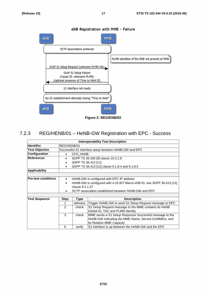
7.2.2 REG/ENB/02 – eNB Registration with EPC – Failure
Interoperability Test Description
Identifier REG/ENB/02
Test Objective Unsuccessful S1 interface setup between eNB and EPC
Configuration CFG_eNB
References 3GPP TS 36.300 [9] clause 19.2.2.8
3GPP TS 36.412 [11]
3GPP TS 36.413 [12] clause 8.7.3.3, clause 9.1.8.4
Applicability MME_TTW
Pre-test conditions eNB is configured with EPC IP address
eNB is configured with a 20 BIT Macro eNB ID, see 3GPP 36.413 [12]
clause 9.2.1.37
EPC does not support eNB’s PLMN identities
SCTP association established between eNB and EPC
Test Sequence Step Type Description
1 stimulus Trigger eNB to send S1 Setup Request message to EPC
2 check S1 Setup Request message contains PLMN identities that are
not identified by EPC
3 check EPC sends to eNB S1 Setup Failure message containing
“Cause IE” indicating “unknown-PLMN” and optionally
containing “Time to Wait IE"
4 verify eNB is not attached to the EPC
5 verify S1 interface is not ready for further operation (UE attach, etc)
6 verify If "Time to Wait IE" was received ENB does not reattempt the
S1 setup before the expiry of the indicated waiting period
ETSI
ETSI TS 103 344 V0.0.22 (2016-06) 17 [Release 10]
Figure 2: REG/ENB/02
7.2.3 REG/HENB/01 – HeNB-GW Registration with EPC - Success
Interoperability Test Description
Identifier REG/HENB/01
Test Objective Successful S1 interface setup between HeNB-GW and EPC
Configuration CFG_HeNB
References 3GPP TS 36.300 [9] clause 19.2.2.8
3GPP TS 36.412 [11]
3GPP TS 36.413 [12] clause 9.1.8.4 and 9.1.8.5
Applicability
Pre-test conditions HeNB-GW is configured with EPC IP address
HeNB-GW is configured with a 20 BIT Macro eNB ID, see 3GPP 36.413 [12]
clause 9.2.1.37
SCTP association established between HeNB-GW and EPC
Test Sequence Step Type Description
1 stimulus Trigger HeNB-GW to send S1 Setup Request message to EPC
2 check S1 Setup Request message to the MME contains its HeNB
Global ID, TAC and PLMN Identity
3 check MME sends a S1 Setup Response Successful message to the
HeNB-GW indicating the MME Name, Served GUMMEIs, and
its Relative MME Capacity
6 verify S1 interface is up between the HeNB-GW and the EPC

ETSI
ETSI TS 103 344 V0.0.22 (2016-06) 18 [Release 10]
Figure 3: REG/HENB/01
7.2.4 REG/HENB/02 – HeNB Registration with HeNB-GW (pre-registered
TAC) – Success
Interoperability Test Description
Identifier REG/HENB/02
Test Objective Successful S1 interface setup between HeNB and HeNB-GW, TAC registered in
EPC
Configuration CFG_HeNB
References 3GPP TS 36.300 [9] clause 19.2.2.8
3GPP TS 36.412 [11]
3GPP TS 36.413 [12] clause 9.1.8.4 and 9.1.8.5
Applicability
Pre-test conditions HeNB is configured with EPC IP address
HeNB is configured with a 28 BIT Home eNB ID, see 3GPP 36.413 [12]
clause 9.2.1.37
SCTP association establishment between HeNB-GW and EPC
S1 interface establishment between HeNB-GW and EPC
SCTP association establishment between HeNB and HeNB-GW
HeNB TAC registered in EPC
Test Sequence Step Type Description
1 stimulus Trigger HeNB to send S1 Setup Request message to
HeNB-GW
2 check S1 Setup Request message to the HeNB-GW contains Home
eNB ID, TAC and PLMN Identity
3 check HeNB-GW sends a S1 Setup Response Successful message to
the HeNB
4 verify S1 interface is up between the HeNB and HeNB-GW, and
between the HeNB-GW and the EPC

ETSI
ETSI TS 103 344 V0.0.22 (2016-06) 19 [Release 10]
Figure 4: REG/HENB/02
7.2.5 REG/HENB/03 – HeNB Registration with HeNB-GW (not pre-
registered TAC) - Success (optional)
Interoperability Test Description
Identifier REG/HENB/03
Test Objective Successful S1 interface setup between HeNB and HeNB-GW with TAC not yet
registered in EPC
Configuration CFG_HeNB
References 3GPP TS 36.300 [9] clause 19.2.2.8
3GPP TS 36.412 [11]
3GPP TS 36.413 [12] clause 9.1.8.7 and 9.1.8.8
Applicability HENBGW_UPDATE_TAC
Pre-test conditions HeNB is configured with EPC IP address
HeNB is configured with a 28 BIT Home eNB ID, see 3GPP 36.413 [12]
clause 9.2.1.37
SCTP association established between HeNB-GW and EPC
S1 interface establishment between HeNB-GW and EPC with pre-
registration of TACs
SCTP association establishment between HeNB and HeNB-GW
HeNB TAC not registered in EPC
Test Sequence Step Type Description
1 stimulus Trigger HeNB to send S1 Setup Request message to
HeNB-GW
2 check S1 Setup Request message to the HeNB-GW contains Home
eNB ID, not registered TAC and PLMN Identity
3 check HeNB-GW sends eNB Configuration Update to the EPC
4 check EPC sends eNB Configuration Update Achnowledge to the

ETSI
ETSI TS 103 344 V0.0.22 (2016-06) 20 [Release 10]
Interoperability Test Description
HeNB-GW
5 check HeNB-GW sends a S1 Setup Response Successful message to
the HeNB
6 verify S1 interface is up between the HeNB and HeNB-GW, and
between the HeNB-GW and the EPC
Figure 5: REG/HENB/03

ETSI
ETSI TS 103 344 V0.0.22 (2016-06) 21 [Release 10]
7.2.6 REG/HENB/04 – Registration with HeNB-GW (not pre-registered
TAC) – Failure (optional)
Interoperability Test Description
Identifier REG/HENB/04
Test Objective Unsuccessful S1 interface setup between HeNB and HeNB-GW with TAC not yet
pre-registered in EPC
Configuration CFG_HeNB
References 3GPP TS 36.300 [9] clause 19.2.2.8
3GPP TS 36.412
3GPP TS 36.413 [12] clause 9.1.8.4 and 9.1.8.6
Applicability HENBGW_BLOCK_UNKNOW_TAC
Pre-test conditions HeNB is configured with EPC IP address
HeNB is configured with a 28 BIT Home eNB ID, see 3GPP 36.413 [12]
clause 9.2.1.37
SCTP association established between HeNB-GW and EPC
S1 interface establishment between HeNB-GW and EPC with pre-
registration of allowed TACs
SCTP association establishment between HeNB and HeNB-GW
HeNB TAC not registered in EPC
Test Sequence Step Type Description
1 stimulus Trigger HeNB to send S1 Setup Request message to
HeNB-GW
2 check S1 Setup Request message to the HeNB-GW contains Home
eNB ID, not registered TAC and known PLMN Identity
3 check HeNB-GW sends to HeNB S1 Setup Failure message optionally
containing “Time to Wait IE"
4 verify HeNB is not successfully attached to the HeNB-GW
5 verify S1 interface is not ready for further operation (UE attach, etc)
6 verify If "Time to Wait IE" was received HeNB does not reattempt the
S1 setup before the expiry of the indicated waiting period
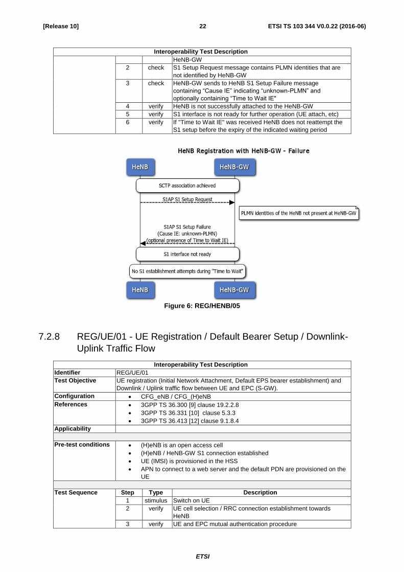
7.2.7 REG/HENB/05 - HeNB Registration with HeNB-GW (unknown
PLMN) – Failure
Interoperability Test Description
Identifier REG/HENB/05
Test Objective Unsuccessful S1 interface setup between HeNB and HeNB-GW
Configuration CFG_HeNB
References 3GPP TS 36.300 [9] clause 19.2.2.8
3GPP TS 36.412 [11]
3GPP TS 36.413 [12] clause 8.7.3.3, clause 9.1.8.4, 9.1.8.5 and 9.2.1.61
Applicability MME_TTW
Pre-test conditions HeNB is configured with HeNB-GW IP address
HeNB is configured with a 28 BIT Home eNB ID, see 3GPP 36.413 [12]
clause 9.2.1.37
HeNB-GW is configured with EPC IP address
HeNB-GW is configured with a 20 BIT Macro eNB ID, see 3GPP 36.413 [12]
clause 9.2.1.37
HeNB-GW does not support HeNB’s PLMN identities
SCTP association establishment between HeNB and HeNB-GW
Test Sequence Step Type Description
1 stimulus Trigger HeNB to send S1 Setup Request message to
ETSI
ETSI TS 103 344 V0.0.22 (2016-06) 22 [Release 10]
Interoperability Test Description
HeNB-GW
2 check S1 Setup Request message contains PLMN identities that are
not identified by HeNB-GW
3 check HeNB-GW sends to HeNB S1 Setup Failure message
containing “Cause IE” indicating “unknown-PLMN” and
optionally containing “Time to Wait IE"
4 verify HeNB is not successfully attached to the HeNB-GW
5 verify S1 interface is not ready for further operation (UE attach, etc)
6 verify If "Time to Wait IE" was received HeNB does not reattempt the
S1 setup before the expiry of the indicated waiting period
Figure 6: REG/HENB/05
7.2.8 REG/UE/01 - UE Registration / Default Bearer Setup / Downlink-
Uplink Traffic Flow
Interoperability Test Description
Identifier REG/UE/01
Test Objective UE registration (Initial Network Attachment, Default EPS bearer establishment) and
Downlink / Uplink traffic flow between UE and EPC (S-GW).
Configuration CFG_eNB / CFG_(H)eNB
References 3GPP TS 36.300 [9] clause 19.2.2.8
3GPP TS 36.331 [10] clause 5.3.3
3GPP TS 36.413 [12] clause 9.1.8.4
Applicability
Pre-test conditions (H)eNB is an open access cell
(H)eNB / HeNB-GW S1 connection established
UE (IMSI) is provisioned in the HSS
APN to connect to a web server and the default PDN are provisioned on the
UE
Test Sequence Step Type Description
1 stimulus Switch on UE
2 verify UE cell selection / RRC connection establishment towards
HeNB
3 verify UE and EPC mutual authentication procedure

ETSI
ETSI TS 103 344 V0.0.22 (2016-06) 23 [Release 10]
Interoperability Test Description
4 verify NAS Security establishment procedure between UE and EPC
5 verify UE capability enquiry procedure
6 verify Default EPS Bearer establishment procedure
7 verify DL/UL traffic flow between UE and EPC (S-GW)

ETSI
ETSI TS 103 344 V0.0.22 (2016-06) 24 [Release 10]

ETSI
ETSI TS 103 344 V0.0.22 (2016-06) 25 [Release 10]
Figure 7: REG/UE/01
7.2.9 REG/UE/02 - UE Deregistration / Network Detach
Interoperability Test Description
Identifier REG/UE/02
Test Objective UE deregistration (Network Detach – powering off)
Configuration CFG_eNB / CFG_(H)eNB
References 3GPP TS 36.300 [9] clause 19.2.2.2
3GPP TS 36.331 [10] clause 5.3.3
3GPP TS 36.413 [12] clause 8.3.2, 9.1.4.6, 9.1.4.7
Applicability
Pre-test conditions (H)eNB / HeNB-GW S1 connection established
UE attached, default EPS bearer established and in IDLE MODE
Test Sequence Step Type Description
2 stimulus Switch off the UE or set to \"flight mode\" or \"offline\" (RF part is
switched off)
3 verify RRC connection establishment towards (H)eNB (NAS: Detach
Request)
4 verify UE and EPC NAS Detach message exchange
5 verify S1 UE Context Release procedure between (H)eNB and EPC
6 verify RRC connection release towards the UE
7 verify UE is successfully detached from the LTE network
8 verify Packet service connection is not available at the UE
Figure 8: REG/UE/02
ETSI
ETSI TS 103 344 V0.0.22 (2016-06) 26 [Release 10]
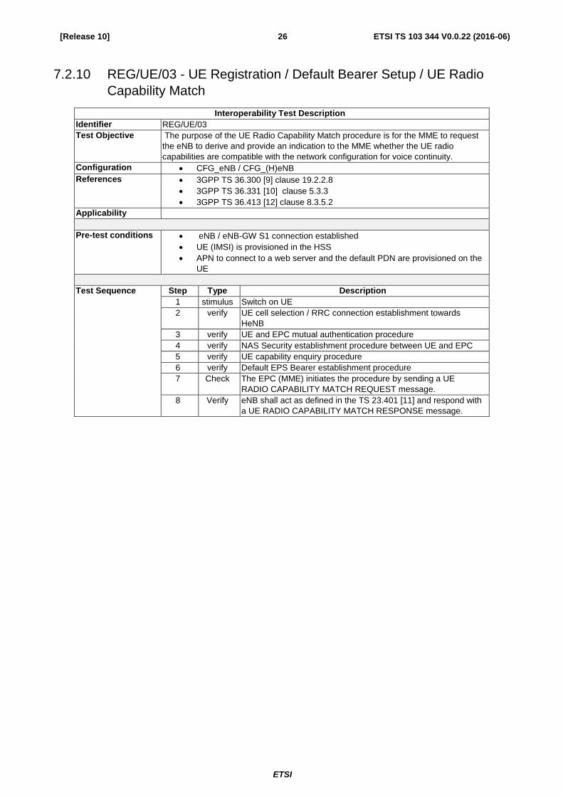
7.2.10 REG/UE/03 - UE Registration / Default Bearer Setup / UE Radio
Capability Match
Interoperability Test Description
Identifier REG/UE/03
Test Objective The purpose of the UE Radio Capability Match procedure is for the MME to request
the eNB to derive and provide an indication to the MME whether the UE radio
capabilities are compatible with the network configuration for voice continuity.
Configuration CFG_eNB / CFG_(H)eNB
References 3GPP TS 36.300 [9] clause 19.2.2.8
3GPP TS 36.331 [10] clause 5.3.3
3GPP TS 36.413 [12] clause 8.3.5.2
Applicability
Pre-test conditions eNB / eNB-GW S1 connection established
UE (IMSI) is provisioned in the HSS
APN to connect to a web server and the default PDN are provisioned on the
UE
Test Sequence Step Type Description
1 stimulus Switch on UE
2 verify UE cell selection / RRC connection establishment towards
HeNB
3 verify UE and EPC mutual authentication procedure
4 verify NAS Security establishment procedure between UE and EPC
5 verify UE capability enquiry procedure
6 verify Default EPS Bearer establishment procedure
7 Check The EPC (MME) initiates the procedure by sending a UE
RADIO CAPABILITY MATCH REQUEST message.
8 Verify eNB shall act as defined in the TS 23.401 [11] and respond with
a UE RADIO CAPABILITY MATCH RESPONSE message.

ETSI
ETSI TS 103 344 V0.0.22 (2016-06) 27 [Release 10]
7.2.11 PS/01 - Paging
Interoperability Test Description
Identifier PS/01
Test Objective Paging message is delivered from (H)eNB to UE
Configuration CFG_eNB / CFG_(H)eNB
References 3GPP TS 23.401 [2] clause 5.3.4.3
3GPP TS 36.413 [12] clause 8.5.2, 9.1.6
3GPP TS 36.300 [9] clause 19.2.2.1
Applicability
Pre-test conditions (H)eNB / HeNB-GW S1 connection established
UE attached, default EPS bearer established and in Idle Mode
UE (IMSI) is provisioned in the HSS
Download data can be provided to the UE
Test Sequence Step Type Description

ETSI
ETSI TS 103 344 V0.0.22 (2016-06) 28 [Release 10]
Interoperability Test Description
1 stimulus Generate downlink traffic for UE
2 verify MME sends S1AP PAGING to (H)eNB
3 verify UE is paged
Figure 9: PS/01
7.2.12 PS/03 - Network initiated E-RAB setup – Distinct Bearer (optional)
Interoperability Test Description
Identifier PS/03
Test Objective Network initiated E-RAB setup with GBR bearer
Configuration CFG_eNB / CFG_(H)eNB
References 3GPP TS 24.301 [4] clause 6.4.2
3GPP TS 36.300 [9] clause 19.2.2.4.1
3GPP TS 36.413 [12] clause 9.1.3.1, 9.1.3.2
Applicability HENBGW_DISTINCT_BEARER
Pre-test conditions (H)eNB / HeNB-GW S1 connection established
UE attached, default EPS bearer established and in IDLE MODE
UE (IMSI) is provisioned in the HSS
APN to connect to a web server and the default PDN are provisioned on the
UE
Test Sequence Step Type Description
1 stimulus From the EPC trigger an E-RAB setup procedure with a GBR
bearer
2 verify Dedicated bearer with the requested QoS and a valid data path
between UE and S-GW is established
3 verify Data transfer between UE and S-GW on the dedicated bearer
with requested QoS set

ETSI
ETSI TS 103 344 V0.0.22 (2016-06) 29 [Release 10]
Figure 10: PS/03

ETSI
ETSI TS 103 344 V0.0.22 (2016-06) 30 [Release 10]
7.2.13 PS/04 - Network initiated E-RAB setup – Combined Bearer
(optional)
Interoperability Test Description
Identifier PS/04
Test Objective Network initiated E-RAB setup with GBR bearer (default and dedicated bearer)
Configuration CFG_eNB / CFG_(H)eNB
References 3GPP TS 24.301 clause 6.4.2
3GPP TS 36.300 clause 19.2.2.4.1
3GPP TS 36.413 clause 9.1.3.1, 9.1.3.2
Applicability HENB_COMBINED_BEARER
Pre-test conditions (H)eNB / HeNB-GW S1 connection established
UE (IMSI) is provisioned in the HSS
APN to connect to a web server and the default PDN are provisioned on the
UE
Test Sequence Step Type Description
1 stimulus The UE attaches to the EPC and is 0in IDLE Mode. This triggers
the establishment of a default and a dedicated bearer.
2 verify Default and Dedicated bearer with the requested QoS and a
valid data path between UE and S-GW is established
3 verify Data transfer between UE and S-GW on the dedicated bearer
with requested QoS set

ETSI
ETSI TS 103 344 V0.0.22 (2016-06) 31 [Release 10]
Figure 11: PS/04
7.2.14 PS/05 - Network initiated E-RAB release
Interoperability Test Description
Identifier PS/05
Test Objective Network initiated ERAB release
Configuration CFG_eNB / CFG_(H)eNB
References 3GPP TS 24.301 [4] clause 6.4.4
3GPP TS 36.300 [9] clause 19.2.2.4.3
3GPP TS 36.413 [12] clause 9.1.3.5, 9.1.3.6
Applicability
Pre-test
conditions (H)eNB / HeNB-GW S1 connection established
UE attached, default EPS bearer established and ongoing data transfer on
default bearer
E-RAB established (GBR or non-GBR) from the UE or the EPC
UE (IMSI) is provisioned in the HSS
APN to connect to the IMS server and the default PDN are provisioned on the
UE
Test Sequence Step Type Description

ETSI
ETSI TS 103 344 V0.0.22 (2016-06) 32 [Release 10]
Interoperability Test Description
1 stimulus Trigger data transfer on E-RAB
2 verify Data transfer between UE and S-GW on the dedicated bearer
3 stimulus Trigger E-RAB release from the network
4 verify E-RAB is released and packet service connection is not available
at the UE
5 verify The on-going data session on the default bearer is not affected
Figure 12: PS/05

ETSI
ETSI TS 103 344 V0.0.22 (2016-06) 33 [Release 10]
7.2.15 PS/06 – E-RAB modification by the network
Interoperability Test Description
Identifier PS/04
Test Objective ERAB modification by the network.
Configuration CFG_eNB / CFG_(H)eNB
References 3GPP TS 24.301 [4] clause 6.4.3
3GPP TS 36.300 [9] clause 19.2.2.4.2
3GPP TS 36.413 [12] clause 9.1.3.3, 9.1.3.4
Applicability
Pre-test
conditions (H)eNB / HeNB-GW S1 connection established
UE attached, default EPS bearer established and ongoing data transfer on
default bearer
E-RAB established (GBR or non-GBR) from the UE or the EPC
UE (IMSI) is provisioned in the HSS
APN to connect to the IMS server and the default PDN are provisioned on the
UE
Test Sequence Step Type Description
1 stimulus Trigger data transfer on E-RAB
2 verify Data transfer between UE and S-GW on the dedicated bearer
3 stimulus Trigger E-RAB modification
4 verify Data transfer on E-RAB and on the default bearer is not stalled at
any point in time during modifications
5 verify Confirm that the QoS on E-RAB is as per the modification

ETSI
ETSI TS 103 344 V0.0.22 (2016-06) 34 [Release 10]
Figure 13: PS/06

ETSI
ETSI TS 103 344 V0.0.22 (2016-06) 35 [Release 10]
7.2.16 CMAS/01 - CMAS Warning Start to List of (H)eNBs
Interoperability Test Description
Identifier CMAS/01
Test Objective Delivery of Warning messages from CMAS Server to a list of HeNBs and distribution
to attached UEs
Configuration CFG_CMAS
References 3GPP TS 36.300 [9] clause 19.2.2.13
3GPP TS 36.413 [12] clause 8.12.1
3GPP TS 29.168 [14] clause 4.3.3
Applicability HENB_CMAS AND MME_CMAS
Pre-test conditions One or more HeNBs connected to a HeNB-GW which in turn is connected
to the CMAS server via an MME
One or more UEs connected to the HeNBs
CMAS connected to the MME
Test Sequence Step Type Description
1 stimulus The CMAS server sends a Write-Replace Warning request with
the Warning Area List set to a list of HeNBs and the TAI list has
the TAI of the HeNB-GW in it
2 check The MME uses the TAI in the TAI list to select the HeNB-GW
and sends the S1AP Write-Replace Warning request to the
appropriate HeNB-GW
3 check The HeNB-GW sends the S1AP Write-Replace Warning request
to the list of HeNBs specified in the Warning Area List
4 check The HeNBs that receive the Write-Replace Warning request
send the message to the UEs under them
5 verify All the UEs under the affected HeNBs get the Warning message

ETSI
ETSI TS 103 344 V0.0.22 (2016-06) 36 [Release 10]
Figure 14: CMAS/01

ETSI
ETSI TS 103 344 V0.0.22 (2016-06) 37 [Release 10]
7.2.17 CMAS/02 - CMAS Warning Start to TAI List
Interoperability Test Description
Identifier CMAS/02
Test Objective Delivery of Warning messages from CMAS Server to a TAI list and distribution to
attached UEs
Configuration CFG_CMAS
References 3GPP TS 36.300 [9] clause 19.2.2.13
3GPP TS 36.413 [12] clause 8.12.1
3GPP TS 29.168 [14] clause 4.3.3
Applicability HENB_CMAS AND MME_CMAS
Pre-test conditions One or more HeNBs connected to a HeNB-GW which in turn is connected
to the CMAS server via an MME
One or more UEs connected to the HeNBs
CMAS connected to the MME
At least one TA with 2 or more HeNB connected
Test Sequence Step Type Description
1 stimulus The CMAS server sends a Write-Replace Warning request with
the Warning Area List set to a list of TAIs and the TAI list has
the TAI of the HeNB-GW in it
2 check The MME uses the TAI in the TAI list to select the HeNB-GW
and sends the S1AP Write-Replace Warning request to the
appropriate HeNB-GW
3 check The HeNB-GW sends the S1AP Write-Replace Warning to the
list of HeNBs specified in the Warning Area List
4 check The HeNBs that receive the Write-Replace Warning request
send the message to the UEs under them
5 verify All the UEs under the affected HeNBs get the Warning message

ETSI
ETSI TS 103 344 V0.0.22 (2016-06) 38 [Release 10]
s
Figure 15: CMAS/02

ETSI
ETSI TS 103 344 V0.0.22 (2016-06) 39 [Release 10]
7.2.18 CMAS/03 - CMAS Warning Stop to List of HeNBs
Interoperability Test Description
Identifier CMAS/03
Test Objective Delivery of Kill messages from CMAS Server to a list of HeNBs and distribution to
attached UEs
Configuration CFG_CMAS
References 3GPP TS 36.300 [9] clause 19.2.2.17
3GPP TS 36.413 [12] clause 8.12.2
3GPP TS 29.168 [14] clause 4.3.3A
Applicability HENB_CMAS AND MME_CMAS
Pre-test conditions One or more HeNBs connected to a HeNB-GW which in turn is connected
to the CMAS server via an MME
One or more UEs connected to the HeNBs
CMAS connected to the MME
Test Sequence Step Type Description
1 stimulus The CMAS server sends the Stop Warning request with the
Warning Area List set to a list of HeNBs and the TAI list has the
TAI of the HeNB-GW in it
2 check The MME uses the TAI in the TAI list to select the HeNB-GW
and sends an S1AP Kill request to the appropriate HeNB-GW
3 check The HeNB-GW sends the S1AP Kill request to the list of HeNBs
specified in the Warning Area List
4 check The HeNBs that receive the Kill request send the message to
the UEs under them
5 verify All the UEs under the affected HeNBs stop receiving the
Warning message being sent out at regular intervals

ETSI
ETSI TS 103 344 V0.0.22 (2016-06) 40 [Release 10]
Figure 16: CMAS/03

ETSI
ETSI TS 103 344 V0.0.22 (2016-06) 41 [Release 10]
7.2.19 CMAS/04 - CMAS Warning Stop to TAI List
Interoperability Test Description
Identifier CMAS/04
Test Objective Delivery of Kill messages from CMAS Server to a TAI list and distribution to attached
UEs
Configuration CFG_CMAS
References 3GPP TS 36.300 [9] clause 19.2.2.17
3GPP TS 36.413 [12] clause 8.12.2
3GPP TS 29.168 [14] clause 4.3.3A
Applicability HENB_CMAS AND MME_CMAS
Pre-test conditions One or more HeNBs connected to a HeNB-GW which in turn is connected
to the CMAS server via an MME
One or more UEs connected to the HeNBs
CMAS connected to the MME
At least one TA with 2 or more HeNB connected
Test Sequence Step Type Description
1 stimulus The CMAS server sends the Stop Warning request with the
Warning Area List set to a list of TAIs and the TAI list has the
TAI of the HeNB-GW in it
2 check The MME uses the TAI in the TAI list to select the HeNB-GW
and sends an S1AP Kill request to the appropriate HeNB-GW
3 check The HeNB-GW sends the S1AP Kill request to the list of HeNBs
specified in the Warning Area List
4 check The HeNBs that receive the Kill request send the message to
the UEs under them
5 verify All the UEs under the affected HeNBs stop receiving the
Warning message being sent out at regular intervals

ETSI
ETSI TS 103 344 V0.0.22 (2016-06) 42 [Release 10]
Figure 17: CMAS/04

ETSI
ETSI TS 103 344 V0.0.22 (2016-06) 43 [Release 10]
7.3 Test Description for Small Cell LTE Remote Plugfest 2015
7.3.1 LIPA/01 - Downlink Traffic Flow through L-GW
Interoperability Test Description
Identifier LIPA/01
Test Objective UE requests connectivity to an APN that is LIPA enabled. Downlink traffic is routed
through the L-GW.
Configuration CFG_LIPA
References 3GPP TS 36.401 [2] clause 5.3.4.1
3GPP TS 36.300 [9] clause 19.2.2.3, 19.2.2.6
3GPP TS 36.413 [12] clause 8.3.1.2, 8.6.2.1
3GPP TR 23.829 [i.1] clause 5.2.3.1
Applicability HENB_LIPA AND MME_LIPA
Pre-test conditions HeNB/ HeNB-GW Normal Operation Mode (S1 Interface connection to
HeNB-GW/EPC established, Radio Connection Established)
L-GW collocated with HeNB.
S5 interface connection from L-GW to S-GW established
UE registered with the network (default bearer is established)
Test Sequence Step Type Description
1 stimulus UE cell selection / RRC connection establishment towards
HeNB
2 stimulus UE request PDN connectivity to LIPA enabled APN
3 check HeNB sends to MME S1AP INITIAL UE MESSAGE with L-GW
address
4 check HeNB sends to MME S1AP UPLINK NAS TRANSPORT with
L-GW address
5 check MME sends to HeNB S1AP INITIAL CONTEXT SETUP
REQUEST with LIPA Correlation Id
6 check HeNB sends to UE NAS ACTIVATE DEFAULT EPS BEARER
CONTEXT REQUEST message with Connectivity type IE
indicating "the PDN connection is considered a LIPA PDN
connection”
7 verify Downlink Traffic flow between UE and L-GW

ETSI
ETSI TS 103 344 V0.0.22 (2016-06) 44 [Release 10]
Figure 18: LIPA/01
7.3.2 CSG/01 – UE Registration with CSG (H)eNB
Interoperability Test Description
Identifier CSG/01
Test Objective Allowed UE registers with the LTE network via a CSG (H)eNB.
Configuration CFG_(H)eNB
References 3GPP TS 25.467 [6] clause 5.1.3
3GPP TS 36.413 [12] clause 9.1.4.1, 9.1.7.1
Applicability HENB_CSG AND MME_CSG
Pre-test conditions HeNB / HeNB-GW S1 connection established
UE (IMSI) is provisioned in the HSS
APN to connect to a web server and the default PDN are provisioned on the
UE
CSG (H)eNB broadcasting a CSG Indicator set to TRUE and a specific CSG
identity
UE is an allowed member of CSG
UE’s CSG whitelist contains broadcast specific CSG Identity
Test Sequence Step Type Description
1 stimulus Switch on UE
2 verify
UE cell selection / RRC connection establishment towards CSG
HeNB
3 check
CSG (H)eNB sends to MME S1AP INITIAL UE MESSAGE
containing CSG Id (and containing the Access Mode IE in case
of hybrid cell)
4 verify UE and EPC mutual authentication procedure
5 verify NAS Security establishment procedure between UE and EPC
6 verify UE capability enquiry procedure

ETSI
ETSI TS 103 344 V0.0.22 (2016-06) 45 [Release 10]
Interoperability Test Description
7 check
During Default EPS Bearer establishment procedure, MME
sends to CSG (H)eNB S1AP INITIAL CONTEXT SETUP
REQUEST (containing CSG Membership Status in case of
hybrid cell)
8 verify DL/UL traffic flow between UE and EPC
Figure 19: CSG/01

ETSI
ETSI TS 103 344 V0.0.22 (2016-06) 46 [Release 10]
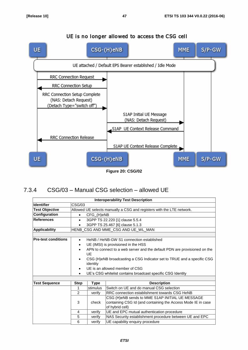
7.3.3 CSG/02 – UE is no longer allowed to access the CSG cell
Interoperability Test Description
Identifier CSG/02
Test Objective Allowed UE has registered with the LTE network via a CSG (H)eNB. After that it
becomes a non member and S1 connection is released.
Configuration CFG_(H)eNB
References 3GPP TS 36.413 [12] clause 8.3.3.1
3GPP TS 25.467 [6] clause 5.1.3, clause 5.10
Applicability HENB_CSG AND MME_CSG
Pre-test conditions HeNB / HeNB-GW S1 connection established
UE (IMSI) is provisioned in the HSS
APN to connect to a web server and the default PDN are provisioned on the
UE
CSG (H)eNB broadcasting a CSG Indicator set to TRUE and a specific CSG
identity
UE is an allowed member of CSG
UE’s CSG whitelist contains broadcast specific CSG Identity
UE attached, default EPS bearer established and in Active Mode (DL/UL
traffic flow between UE and S-GW)
Test Sequence Step Type Description
1 stimulus
Configure HSS so that UE is no longer member of CSG; HSS
will inform MME about UE membership status change
2 verify
MME sends to CSG (H)eNB S1AP UE Context Release
command containing cause ‘CSG Subscription Expiry’
3 verify RRC connection release towards the UE
4 check
CSG (H)eNB sends to MME S1AP UE Context Release
Complete
5 verify UE is successfully detached from the LTE network
6 verify Packet service connection is not available at the UE
ETSI
ETSI TS 103 344 V0.0.22 (2016-06) 47 [Release 10]
Figure 20: CSG/02
7.3.4 CSG/03 – Manual CSG selection – allowed UE
Interoperability Test Description
Identifier CSG/03
Test Objective Allowed UE selects manually a CSG and registers with the LTE network.
Configuration CFG_(H)eNB
References 3GPP TS 22.220 [1] clause 5.5.4
3GPP TS 25.467 [6] clause 5.1.3
Applicability HENB_CSG AND MME_CSG AND UE_WL_MAN
Pre-test conditions HeNB / HeNB-GW S1 connection established
UE (IMSI) is provisioned in the HSS
APN to connect to a web server and the default PDN are provisioned on the
UE
CSG (H)eNB broadcasting a CSG Indicator set to TRUE and a specific CSG
identity
UE is an allowed member of CSG
UE’s CSG whitelist contains broadcast specific CSG Identity
Test Sequence Step Type Description
1 stimulus Switch on UE and do manual CSG selection
2 verify RRC connection establishment towards CSG HeNB
3 check
CSG (H)eNB sends to MME S1AP INITIAL UE MESSAGE
containing CSG Id (and containing the Access Mode IE in case
of hybrid cell)
4 verify UE and EPC mutual authentication procedure
5 verify NAS Security establishment procedure between UE and EPC
6 verify UE capability enquiry procedure

ETSI
ETSI TS 103 344 V0.0.22 (2016-06) 48 [Release 10]
Interoperability Test Description
7 check
During Default EPS Bearer establishment procedure, MME
sends to CSG (H)eNB S1AP INITIAL CONTEXT SETUP
REQUEST (containing CSG Membership Status in case of
hybrid cell)
8 verify DL/UL traffic flow between UE and EPC

ETSI
ETSI TS 103 344 V0.0.22 (2016-06) 49 [Release 10]
ETSI
ETSI TS 103 344 V0.0.22 (2016-06) 50 [Release 10]
Figure 21: CSG/03
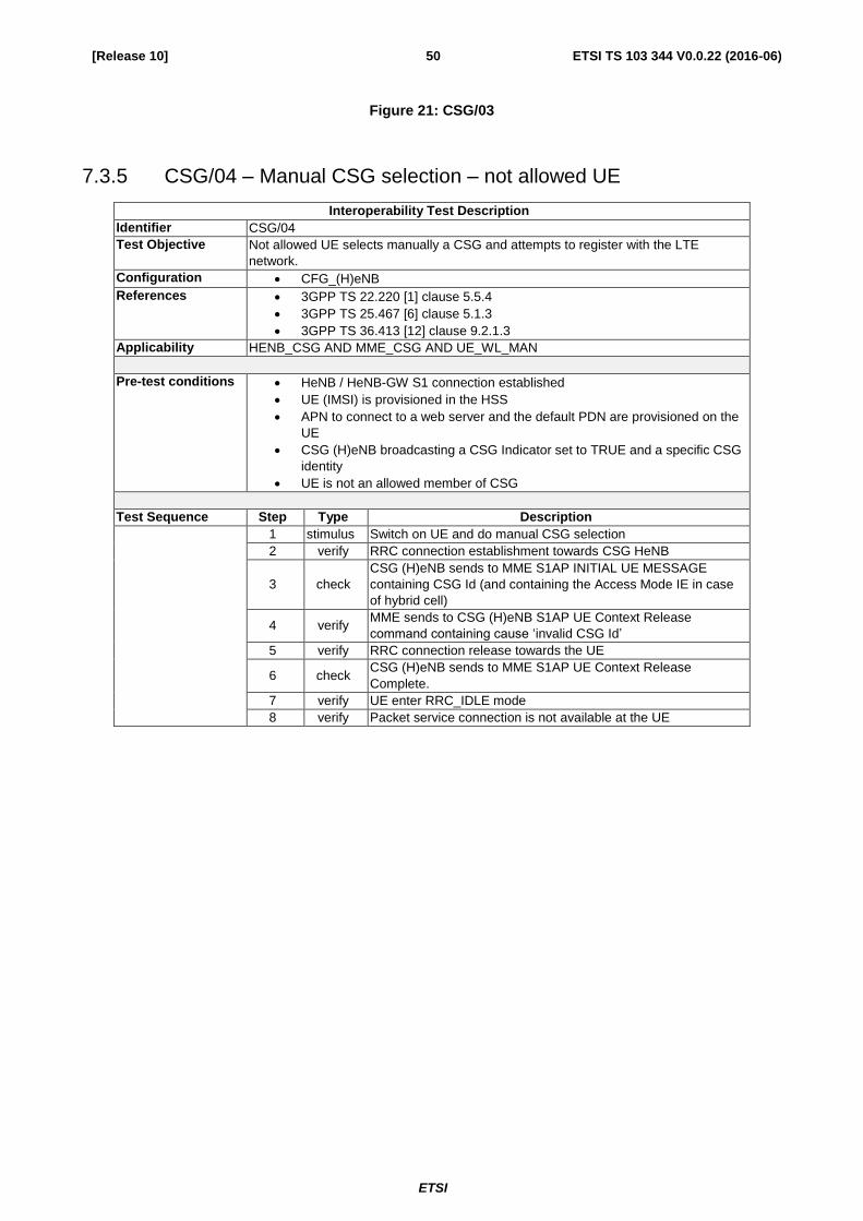
7.3.5 CSG/04 – Manual CSG selection – not allowed UE
Interoperability Test Description
Identifier CSG/04
Test Objective Not allowed UE selects manually a CSG and attempts to register with the LTE
network.
Configuration CFG_(H)eNB
References 3GPP TS 22.220 [1] clause 5.5.4
3GPP TS 25.467 [6] clause 5.1.3
3GPP TS 36.413 [12] clause 9.2.1.3
Applicability HENB_CSG AND MME_CSG AND UE_WL_MAN
Pre-test conditions HeNB / HeNB-GW S1 connection established
UE (IMSI) is provisioned in the HSS
APN to connect to a web server and the default PDN are provisioned on the
UE
CSG (H)eNB broadcasting a CSG Indicator set to TRUE and a specific CSG
identity
UE is not an allowed member of CSG
Test Sequence Step Type Description
1 stimulus Switch on UE and do manual CSG selection
2 verify RRC connection establishment towards CSG HeNB
3 check
CSG (H)eNB sends to MME S1AP INITIAL UE MESSAGE
containing CSG Id (and containing the Access Mode IE in case
of hybrid cell)
4 verify
MME sends to CSG (H)eNB S1AP UE Context Release
command containing cause ‘invalid CSG Id’
5 verify RRC connection release towards the UE
6 check
CSG (H)eNB sends to MME S1AP UE Context Release
Complete.
7 verify UE enter RRC_IDLE mode
8 verify Packet service connection is not available at the UE

ETSI
ETSI TS 103 344 V0.0.22 (2016-06) 51 [Release 10]
Figure 22: CSG/04
7.3.6 CSG/05 - UE Registration with hybrid (H)eNB
Interoperability Test Description
Identifier CSG/05
Test Objective Member UE1 and non-member UE2 register with the LTE network via a hybrid
(H)eNB.
Configuration CFG_(H)eNB
References 3GPP TS 25.467 [6] clause 5.1.3
Applicability HENB_CSG AND MME_CSG
Pre-test conditions HeNB / HeNB-GW S1 connection established
UE (IMSI) is provisioned in the HSS
APN to connect to a web server and the default PDN are provisioned on the
UE
CSG (H)eNB broadcasting a CSG Indicator set to FALSE and a specific
CSG identity
UE1 is an allowed member of CSG
UE’s CSG whitelist contains broadcast specific CSG Identity
UE2 is not an allowed member of CSG
HSS/MME configured/programmed to release a non-member UE 10
seconds after UE context establishment
Test Sequence Step Type Description
1 stimulus Switch on UE1
2 verify
UE cell selection / RRC connection establishment towards
hybrid CSG (H)eNB
3 check
hybrid CSG (H)eNB sends to MME S1AP INITIAL UE
MESSAGE containing CSG Id and containing Cell Access Mode
indicating hybrid
4 verify UE and EPC mutual authentication procedure

ETSI
ETSI TS 103 344 V0.0.22 (2016-06) 52 [Release 10]
Interoperability Test Description
5 verify NAS Security establishment procedure between UE and EPC
6 verify UE capability enquiry procedure
7 check
During Default EPS Bearer establishment procedure, MME
sends to hybrid CSG (H)eNB S1AP INITIAL CONTEXT SETUP
REQUEST containing CSG Membership Status with value
‘member’ for UE1 and ‘non-member’ for UE2
8a verify DL/UL traffic flow between UE1 and EPC
8b verify
DL/UL traffic flow between UE2 and EPC
After 10s S1 UE Context Release and RRC Connection
Release procedure for UE2
9 verify
Switch on UE2
Repeat steps 2 – 7 and step 8b with UE2
Figure 23: CSG/05

ETSI
ETSI TS 103 344 V0.0.22 (2016-06) 53 [Release 10]
7.3.7 IMS/01 – UE SIP Registration
Interoperability Test Description
Identifier IMS/01
Test Objective UE registers with the LTE network to receive services that require registration (Initial
Network Registration). Default EPS bearer is also established as part of Network
Attachment procedure. UE performs an IMS SIP Registration.
Configuration CFG_IMS
References 3GPP 24.229 [8] subclause 5.1.1
3GPP 34.229 subclause 8.1, Annex A.1 Default messages for IMS
Registration
Applicability HENB_VOLTE AND MME_VOLTE
Pre-test conditions eNB / eNB-GW S1 connection established
UE (IMSI) is provisioned in the HSS
At least IMS APN configured in UE
SIP client on UE ready to start Registration procedure
Test Sequence Step Type Description
1 stimulus Switch on UE
2 verify UE intiates LTE registration / RRC connection establishment
towards HeNB
3 verify UE and EPC mutual authentication procedure
4 verify NAS Security establishment procedure between UE and EPC
5 verify UE capability enquiry procedure
6 verify Default EPS Bearer establishment procedure
7 check eNB activates dedicated bearer (QCI:5)(Optional)
Note:IMS Registration can be performed on default bearer .
8 verify UE SIP Registration successful
Expected sequence for SIP Registration
Direction Message Comment
UE CFG_IM
S
1 REGISTER UE sends initial registration for IMS services.
2 401 Unauthorized The IMS Server responds with a valid AKAv1-
MD5 authentication challenge and security
mechanisms supported by the network.
3 REGISTER UE completes the security negotiation
procedures, sets up a temporary set of SAs and
uses those for sending another REGISTER with
AKAv1-MD5 credentials.
4 200 OK The IMS Server responds with 200 OK.
5 SUBSCRIBE UE subscribes to its registration event package.
6 200 OK The IMS Server responds SUBSCRIBE with 200
OK
7 NOTIFY The IMS Server sends initial NOTIFY for
registration event package, containing full
registration state information for the registered
public user identity in the XML body
8 200 OK The UE responds the NOTIFY with 200 OK

ETSI
ETSI TS 103 344 V0.0.22 (2016-06) 54 [Release 10]
Figure 24: IMS/01

ETSI
ETSI TS 103 344 V0.0.22 (2016-06) 55 [Release 10]
7.3.8 IMS/02 – UE SIP Emergency Registration and Emergency Call
Interoperability Test Description
Identifier IMS/02
Test Objective To verify that the UE can correctly register to IMS emergency services and initiate an
IMS emergency call when UE is registered to IMS non-emergency services of the
HPLMN.
Configuration CFG_IMS
References 3GPP TS 24.229 [10] clause 5.1.6.1
3GPP TS 34.229 [8] clause 19.1.1
3GPP TS 34.229 annex C 20
3GPP TS 34.229 annex C.22
3GPP TS 34.229 annex A.1 Default messages for IMS Registration
Applicability HENB_VOLTE AND MME_VOLTE
Pre-test conditions Support for IMS emergency services / speech
(H)eNB / HeNB-GW S1 connection established
UE (IMSI) is provisioned in the HSS
At least IMS APN configured in UE
SIP client on UE ready to start IMS Emergency Registration procedure
Test Sequence Step Type Description
1 stimulus UE initiates LTE registration/Default Bearer is established
2 check IMS SIP Emergency Registration is successful
3 stimulus Use SIP agent to start Emergency call
4 verify Dedicated EPS Bearer establishment procedure (QCI:1 voice)
5 verify Emergency call is established
6 verify Bidirectional RTP channel established using the dedicated voice
bearer
Expected sequence for Emergency Registration and Emergency Call:
Direction Message Comment
UE CFG_IMS
1 REGISTER The UE sends initial IMS emergency registration
2 401 Unauthorized The IMS Server responds with a valid AKAv1-
MD5 authentication challenge and security
mechanisms supported by the network.
3 REGISTER The UE completes the security negotiation
procedures, sets up a temporary set of SAs and
uses those for sending another REGISTER with
AKAv1-MD5 credentials.
4 200 OK The IMS Server responds with 200 OK.
5 INVITE UE sends INVITE with the first SDP offer.
6 100 Trying IMS Server sends a 100 Trying provisional
response.
7 180 Ringing IMS Server sends a 180 Ringing.
8 200 OK IMS Server responds INVITE with 200 OK.
9 ACK UE acknowledges.

ETSI
ETSI TS 103 344 V0.0.22 (2016-06) 56 [Release 10]

ETSI
ETSI TS 103 344 V0.0.22 (2016-06) 57 [Release 10]
7.3.9 IMS/03 – UE SIP Originating Call (VoLTE)
Interoperability Test Description
Identifier IMS/03
Test Objective SIP registered UE starts VoLTE call to other UE.
Configuration CFG_IMS
References 3GPP TS 24.229 [8] clause 5.1.3, 3GPP TS 34.229 clause 12.12, 3GPP TS
36.508 clause 4.5A.6.3
Applicability HENB_VOLTE AND MME_VOLTE
Pre-test conditions
Support for speech
(H)eNB / HeNB-GW S1 connection established
UE (IMSI) is provisioned in the HSS
At least IMS APN configured in UE
SIP client on UE ready to start Registration procedure
UE (UE1) registered in IMS
Second UE (UE2) registered in IMS and reachable to terminate call
Test Sequence Step Type Description
1 stimulus UE performs LTE registration/Default Bearer is established
2 check SIP Registration is successful
3 stimulus Use SIP agent to start VoLTE call to other UE
4 verify Dedicated EPS Bearer establishment procedure (QCI:1 voice)
5 verify VoLTE call to UE2 is established
6 verify Bidirectional RTP channel established using the dedicated voice
bearer between UEs
Expected sequence for IMS Call:
Direction Message Comment
UE CFG_IMS
1 Make the UE attempt an IMS
speech call
2 INVITE UE sends INVITE with the first SDP offer.
3 100 Trying IMS Server sends a 100 Trying provisional
response.
4 183 Session Progress IMS Server sends an SDP answer.
5 PRACK UE acknowledges and optionally offers a
second SDP if a dedicated EPS bearer is
established by the network.
6 200 OK IMS Server sends a 200 OK and answers the
second SDP if present.
7 UPDATE Optional step: UE sends a second SDP if a
dedicated EPS bearer is established by the
network.
8 200 OK Optional step: IMS Server sends a 200 OK.
9 180 Ringing IMS Server sends a 180 Ringing.
10 PRACK UE acknowledges.
11 200 OK IMS Server responds PRACK with 200 OK.
12 200 OK IMS Server responds INVITE with 200 OK.
13 ACK UE acknowledges.

ETSI
ETSI TS 103 344 V0.0.22 (2016-06) 58 [Release 10]
Figure 25: IMS/02
7.3.10 IMS/04 – UE SIP Terminating Call (VoLTE)
Interoperability Test Description
Identifier IMS/04
Test Objective SIP registered UE receives VoLTE call to other UE.
Configuration CFG_IMS
References 3GPP TS 24.229 [8] clause 5.1.4 ,3GPP TS 34.229 clause 12.13 , 3GPP TS
36.508 clause 4.5A.7.3
Applicability HENB_VOLTE AND MME_VOLTE
Pre-test conditions Support for speech
(H)eNB / HeNB-GW S1 connection established
UE (IMSI) is provisioned in the HSS
At least IMS APN configured in UE
SIP client on UE ready to start Registration procedure
UE (UE1) registered in IMS
Second UE (UE2) registered in IMS and ready to originate call
Test Sequence Step Type Description
1 stimulus UE performs LTE registration/Default Bearer is established
2 check SIP Registration is successful

ETSI
ETSI TS 103 344 V0.0.22 (2016-06) 59 [Release 10]
Interoperability Test Description
3 stimulus Use SIP agent on UE2 to originate VoLTE call
4 stimulus Accept incoming VoLTE call
5 verify Dedicated EPS Bearer establishment procedure (QCI:1 voice)
6 verify VoLTE call from UE2 is established
7 verify Bidirectional RTP channel established using the dedicated voice
bearer between UEs
Expected sequence for IMS MT call
Direction Message Comment
UE CFG_I
MS
1 INVITE IMS Server sends INVITE with the first SDP
offer.
2 Void
3 100 Trying (Optional) The UE responds with a 100 Trying
provisional response
4 183 Session Progress The UE sends 183 response reliably with the
SDP answer to the offer in INVITE
5 PRACK IMS Server acknowledges the receipt of 183
response from the UE.
6 200 OK The UE responds to PRACK with 200 OK.
7 UPDATE IMS Server sends an UPDATE with SDP offer
indicating IMS Server reserved resources.
8 200 OK The UE acknowledges the UPDATE with 200
OK and includes SDP answer to acknowledge
its current precondition status.
9 180 Ringing (Optional) The UE responds to INVITE with 180
Ringing.
10 PRACK (Optional) IMS Server shall send PRACK only if
the 180 response contains 100rel option tag
within the Require header.
11 200 OK (Optional) The UE acknowledges the PRACK
with 200 OK.
11A Make UE accept the speech AMR offer.
12 200 OK The UE responds to INVITE with a 200 OK final
response after the user answers the call.
13 ACK The IMS Server acknowledges the receipt of
200 OK for INVITE.
14 BYE The IMS Server sends BYE to release the call.
15 200 OK The UE sends 200 OK for the BYE request and
ends the call.

ETSI
ETSI TS 103 344 V0.0.22 (2016-06) 60 [Release 10]
Figure 26: IMS/03
7.3.11 IMS/05 – UE Originating Video Call
Interoperability Test Description
Identifier IMS/05
Test Objective SIP registered UE starts video call to other UE.
Configuration CFG_IMS
References 3GPP TS 24.229 [8] clause 5.1.3
Applicability HENB_VOLTE AND MME_VOLTE AND UE_VIDEO
Pre-test conditions (H)eNB / HeNB-GW S1 connection established
UE (IMSI) is provisioned in the HSS
At least IMS APN configured in UE
SIP client on UE ready to start Registration procedure
UE (UE1) registered in IMS
Second UE (UE2) registered in IMS and reachable to terminate call
Both UEs capable for video calls
Test Sequence Step Type Description
1 stimulus UE performs LTE registration/Default Bearer is established
2 check SIP Registration is successful
3 stimulus Use SIP agent to start video call to other UE (UE2)

ETSI
ETSI TS 103 344 V0.0.22 (2016-06) 61 [Release 10]
Interoperability Test Description
4 verify Dedicated EPS Bearer establishment procedure (QCI:2 video)
5a verify Video call to UE2 is established (5b step occurs parallely)
5b stimulus eNB configures two new RLC-UM data radio bearers with
condition DRB (0,2), associated with the dedicated EPS bearer
context.
6 verify Bidirectional RTP channel established using the dedicated video
bearer between UEs
Note: Please refer to 3GPP TS 36.508 subclause 4.5A.8.
Expected sequence for MO IMS video call
Direction Message Comment
UE CFG_
IMS
1 Make the UE attempt an IMS video call
2 INVITE UE sends INVITE with the first SDP offer.
3 100 Trying IMS Server sends a 100 Trying provisional
response.
4 183 Session Progress IMS Server sends an SDP answer.
5 PRACK UE acknowledges and optionally offer a
second SDP if a dedicated EPS bearer is
established by the network.
6 200 OK IMS Server sends a 200 OK and answers the
second SDP if present.
7 UPDATE Optional step: UE sends a second SDP if a
dedicated EPS bearer is established by the
network.
8 200 OK Optional step: IMS Server sends a 200 OK.
9 180 Ringing IMS Server sends a 180 Ringing.
10 PRACK UE acknowledges.
11 200 OK IMS Server responds PRACK with 200 OK.
12 200 OK IMS Server responds INVITE with 200 OK.
13 ACK UE acknowledges.
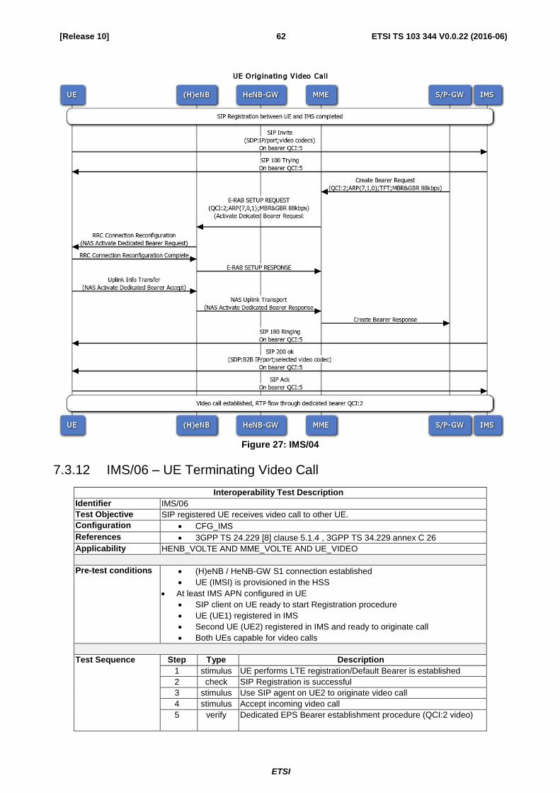
ETSI
ETSI TS 103 344 V0.0.22 (2016-06) 62 [Release 10]
Figure 27: IMS/04
7.3.12 IMS/06 – UE Terminating Video Call
Interoperability Test Description
Identifier IMS/06
Test Objective SIP registered UE receives video call to other UE.
Configuration CFG_IMS
References 3GPP TS 24.229 [8] clause 5.1.4 , 3GPP TS 34.229 annex C 26
Applicability HENB_VOLTE AND MME_VOLTE AND UE_VIDEO
Pre-test conditions (H)eNB / HeNB-GW S1 connection established
UE (IMSI) is provisioned in the HSS
At least IMS APN configured in UE
SIP client on UE ready to start Registration procedure
UE (UE1) registered in IMS
Second UE (UE2) registered in IMS and ready to originate call
Both UEs capable for video calls
Test Sequence Step Type Description
1 stimulus UE performs LTE registration/Default Bearer is established
2 check SIP Registration is successful
3 stimulus Use SIP agent on UE2 to originate video call
4 stimulus Accept incoming video call
5 verify Dedicated EPS Bearer establishment procedure (QCI:2 video)

ETSI
ETSI TS 103 344 V0.0.22 (2016-06) 63 [Release 10]
Interoperability Test Description
6a verify Video call from UE2 is established
6b stimulus eNB configures two new RLC-UM data radio bearers with
condition DRB (0,2), associated with the dedicated EPS bearer
context.
7 verify Bidirectional RTP channel established using the dedicated video
bearer between UEs
Note: Please refer to 3GPP TS 36.508 subclause 4.5A.9.
Expected sequence for IMS MT video call
Direction Message Comment
UE CFG_
IMS
1 INVITE IMS Server sends INVITE with the first SDP
offer.
2 Void
3 100 Trying (Optional) The UE responds with a 100 Trying
provisional response
4 183 Session Progress The UE sends 183 response reliably with the
SDP answer to the offer in INVITE
5 PRACK IMS Server acknowledges the receipt of 183
response from the UE.
6 200 OK The UE responds to PRACK with 200 OK.
7 UPDATE IMS Server sends an UPDATE with SDP offer
indicating IMS Server reserved resources.
8 200 OK The UE acknowledges the UPDATE with 200
OK and includes SDP answer to acknowledge
its current precondition status.
9 180 Ringing (Optional) The UE responds to INVITE with 180
Ringing.
10 PRACK (Optional) IMS Server shall send PRACK only if
the 180 response contains 100rel option tag
within the Require header.
11 200 OK (Optional) The UE acknowledges the PRACK
with 200 OK.
11A Make UE accept the video offer.
12 200 OK The UE responds to INVITE with a 200 OK final
response after the user answers the call.
13 ACK The IMS Server acknowledges the receipt of
200 OK for INVITE.
14 BYE The IMS Server sends BYE to release the call.
15 200 OK The UE sends 200 OK for the BYE request and
ends the call.

ETSI
ETSI TS 103 344 V0.0.22 (2016-06) 64 [Release 10]
Figure 28: IMS/05
7.3.13 IMS/07 – MO SMS over IMS
Interoperability Test Description
Identifier IMS/07
Test Objective To verify that the UE1 is able to send a Mobile Originating SMS over IMS to UE2
Configuration CFG_IMS
References 3GPP TS 24.229 [8] clause 5.1.4 , 3GPP TS 34.229 clause 18.1
Applicability HENB_VOLTE AND MME_VOLTE AND UE_VIDEO
Pre-test conditions (H)eNB / HeNB-GW S1 connection established
UE (IMSI) is provisioned in the HSS
At least IMS APN configured in UE
SIP client on UE ready to start Registration procedure
Test Sequence Step Type Description
1 stimulus UE performs LTE registration/Default Bearer is established
2 verify SIP registration is successful
3 stimulus Use SIP agent on UE1 to send MO SMS
4 verify UE recieves a status report

ETSI
ETSI TS 103 344 V0.0.22 (2016-06) 65 [Release 10]
Expected sequence for MO SMS over IMS
Direction Message Comment
UE CFG_IMS
1 SIP MESSAGE request UE sends a SIP MESSAGE request including a
vnd.3gpp.sms payload that contains a short
message
2 202 Accepted IMS Server responds with 202 Accepted
3 SIP MESSAGE request IMS Server sends a SIP MESSAGE request
including a vnd.3gpp.sms payload that contains
the short message submission report indicating a
positive acknowledgement of the short message
sent by the UE at Step 1
4 200 OK UE responds with 200 OK
5 SIP MESSAGE request IMS Server sends a SIP MESSAGE request
including a vnd.3gpp.sms payload that contains a
status report
6 200 OK UE responds with 200 OK
7 SIP MESSAGE request UE sends a SIP MESSAGE request including a
vnd.3gpp.sms payload that contains a delivery
report for the status report received at Step 5
8 202 Accepted IMS Server responds with 202 Accepted
Figure 7.3.13

ETSI
ETSI TS 103 344 V0.0.22 (2016-06) 66 [Release 10]
7.3.14 IMS/08 – MT SMS over IMS
Interoperability Test Description
Identifier IMS/08
Test Objective SIP registered UE receives SMS from other UE.
Configuration CFG_IMS
References 3GPP TS 24.229 [8] clause 5.1.4 , 3GPP TS 34.229 annex C 26
Applicability HENB_VOLTE AND MME_VOLTE AND UE_VIDEO
Pre-test conditions (H)eNB / HeNB-GW S1 connection established
UE (IMSI) is provisioned in the HSS
At least IMS APN configured in UE
SIP client on UE ready to start Registration procedure
Test Sequence Step Type Description
1 stimulus UE performs LTE registration/Default Bearer is established
2 verify SIP registration is successful
3 stimulus Use eNB to send MT SMS over IMS
4 verify UE responds with a delivery report
Expected sequence for MT SMS over IMS
Direction Message Comment
UE CFG_IM
S
1 MESSAGE The IMS Server sends a Short Message.
2 200 OK The UE responds with 200 OK.
3 MESSAGE The UE responds with a delivery report.
4 202 ACCEPTED The IMS Server sends an accepted response.
Figure 7.3.14
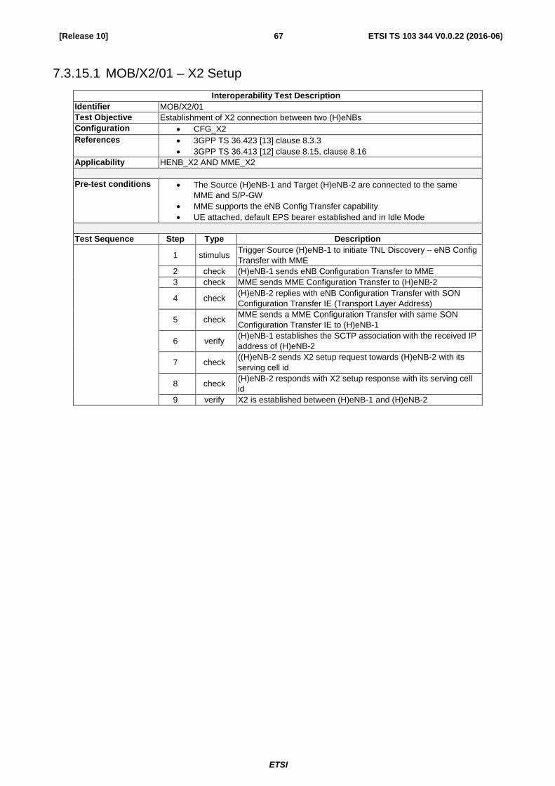
ETSI
ETSI TS 103 344 V0.0.22 (2016-06) 67 [Release 10]
7.3.15.1 MOB/X2/01 – X2 Setup
Interoperability Test Description
Identifier MOB/X2/01
Test Objective Establishment of X2 connection between two (H)eNBs
Configuration CFG_X2
References 3GPP TS 36.423 [13] clause 8.3.3
3GPP TS 36.413 [12] clause 8.15, clause 8.16
Applicability HENB_X2 AND MME_X2
Pre-test conditions The Source (H)eNB-1 and Target (H)eNB-2 are connected to the same
MME and S/P-GW
MME supports the eNB Config Transfer capability
UE attached, default EPS bearer established and in Idle Mode
Test Sequence Step Type Description
1 stimulus
Trigger Source (H)eNB-1 to initiate TNL Discovery – eNB Config
Transfer with MME
2 check (H)eNB-1 sends eNB Configuration Transfer to MME
3 check MME sends MME Configuration Transfer to (H)eNB-2
4 check
(H)eNB-2 replies with eNB Configuration Transfer with SON
Configuration Transfer IE (Transport Layer Address)
5 check
MME sends a MME Configuration Transfer with same SON
Configuration Transfer IE to (H)eNB-1
6 verify
(H)eNB-1 establishes the SCTP association with the received IP
address of (H)eNB-2
7 check
((H)eNB-2 sends X2 setup request towards (H)eNB-2 with its
serving cell id
8 check
(H)eNB-2 responds with X2 setup response with its serving cell
id
9 verify X2 is established between (H)eNB-1 and (H)eNB-2
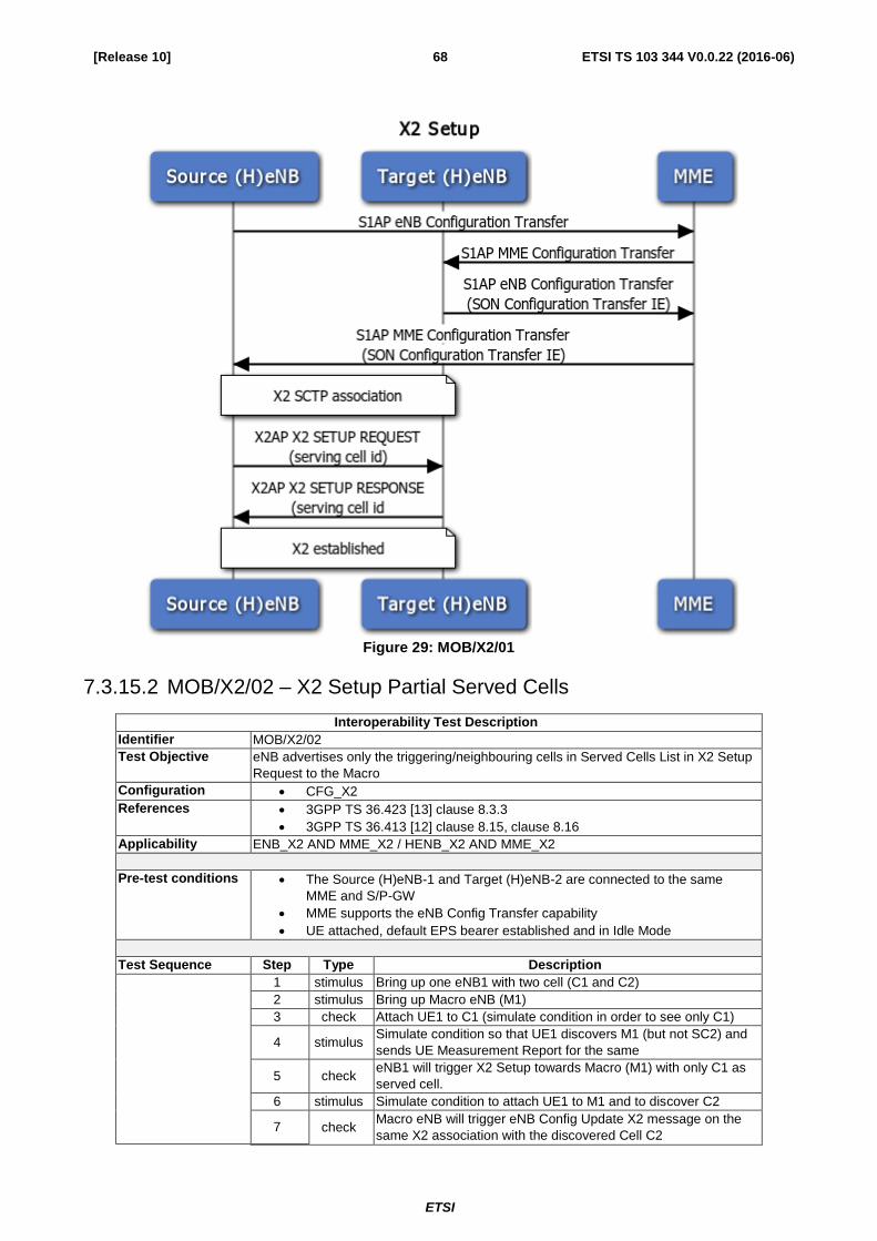
ETSI
ETSI TS 103 344 V0.0.22 (2016-06) 68 [Release 10]
Figure 29: MOB/X2/01
7.3.15.2 MOB/X2/02 – X2 Setup Partial Served Cells
Interoperability Test Description
Identifier MOB/X2/02
Test Objective eNB advertises only the triggering/neighbouring cells in Served Cells List in X2 Setup
Request to the Macro
Configuration CFG_X2
References 3GPP TS 36.423 [13] clause 8.3.3
3GPP TS 36.413 [12] clause 8.15, clause 8.16
Applicability ENB_X2 AND MME_X2 / HENB_X2 AND MME_X2
Pre-test conditions The Source (H)eNB-1 and Target (H)eNB-2 are connected to the same
MME and S/P-GW
MME supports the eNB Config Transfer capability
UE attached, default EPS bearer established and in Idle Mode
Test Sequence Step Type Description
1 stimulus Bring up one eNB1 with two cell (C1 and C2)
2 stimulus Bring up Macro eNB (M1)
3 check Attach UE1 to C1 (simulate condition in order to see only C1)
4 stimulus
Simulate condition so that UE1 discovers M1 (but not SC2) and
sends UE Measurement Report for the same
5 check
eNB1 will trigger X2 Setup towards Macro (M1) with only C1 as
served cell.
6 stimulus Simulate condition to attach UE1 to M1 and to discover C2
7 check
Macro eNB will trigger eNB Config Update X2 message on the
same X2 association with the discovered Cell C2

ETSI
ETSI TS 103 344 V0.0.22 (2016-06) 69 [Release 10]
Interoperability Test Description
8 verify
Macro should send eNB Config Update X2 message on the
same X2 association since a new neighbour has been
discovered with the same peer
7.3.16 MOB/X2/03 – X2 based Handover
Interoperability Test Description
Identifier MOB/X2/03
Test Objective UE connected to Source (H)eNB successfully hands over to a Target (H)eNB using
X2 messages
Configuration CFG_X2
References 3GPP TS 36.423 [13]
Applicability HENB_X2 AND MME_X2
Pre-test conditions The Source (H)eNB-1 and Target (H)eNB-2 are connected to the same
MME and S/P-GW
MME supports the eNB Config Transfer capability
The Source and Target (H)eNBs have established a X2 link
APN to connect to a web server and the default PDN are provisioned on the
UE
UL/DL data transfer between UE and Source (H)eNB-1
Test Sequence Step Type Description
1 stimulus
Raise attenuation towards Source (H)eNB-1 and lower
attenuation towards Target (H)eNB-2-Simu
2 verify
When the RSRP of the Target (H)eNB-2-Simu at the UE is
better than the Source (H)eNB by the configured amount, then
the UE sends a measurement report to the Source (H)eNB
3 check
The Source (H)eNB-1 initiates UE handover to the Target
(H)eNB-2 using X2AP HANDOVER REQUEST
4 check
The Target (H)eNB-2 responds with X2AP HANDOVER
REQUEST ACKNOWLEDGE
5 check
The Source (H)eNB sends the
RRCConnectionReconfigurationRequest with the Target
(H)eNB-2 information to the UE
6 check
The Source (H)eNB also sends SN STATUS TRANSFER with
the relevant PDCP SN information to the Target (H)eNB-2 and
starts forwarding the data traffic to the Target (H)eNB-2
7 check
After the UE synchronizes and successfully accesses the Target
(H)eNB, the UE sends
RRCConnectionReconfigurationComplete to the Target (H)eNB
8 check
The Target (H)eNB sends PATH SWITCH REQUEST to the
MME to inform the MME that the UE has switched cells
9 check
The MME informs the S/PGW to move the data path of the UE
to the Target (H)eNB and sends PATH SWITCH REQUEST
ACK
10 check
Now that the UE has successfully moved to the Target (H)eNB,
the Target (H)eNB sends UE CONTEXT RELEASE to the
Source (H)eNB to clear the UE context information
11 verify
The UE is able to successfully continue the PS call via the
Target (H)eNB

ETSI
ETSI TS 103 344 V0.0.22 (2016-06) 70 [Release 10]
Figure 30: MOB/X2/02
7.3.17 MOB/X2/04 – X2 Reset
Interoperability Test Description
Identifier MOB/X2/04
Test Objective Reset of X2 connection between two (H)eNBs
Configuration CFG_X2
References 3GPP TS 36.423 [13] clause 8.3.4
Applicability HENB_X2 AND MME_X2
Pre-test conditions The Source (H)eNB-1 and Target (H)eNB-2 are connected to the same
MME and S/P-GW
MME supports the eNB Config Transfer capability
UE attached, default EPS bearer established and in Idle Mode
(H)eNBs have completed X2 setup
Test Sequence Step Type Description
1 stimulus Trigger Source (H)eNB-1 to reset X2 connection to (H)eNB-2
2 check (H)eNB-1 sends Reset Request to neighbouring (H)eNB-2
3 check (H)eNB-2 sends Reset Response to (H)eNB-1
4 verify X2 is disconnected between (H)eNB-1 and (H)eNB-2

ETSI
ETSI TS 103 344 V0.0.22 (2016-06) 71 [Release 10]
Figure 31: MOB/X2/03
7.3.18 MOB/X2/05 – X2 Load Indication
Interoperability Test Description
Identifier MOB/X2/05
Test Objective X2 load indication procedure between two (H)eNBs
Configuration CFG_X2
References 3GPP TS 36.423 [13] clause 8.3.1
Applicability HENB_X2 AND MME_X2
Pre-test conditions The Source (H)eNB-1 and Target (H)eNB-2 are connected to the same
MME and S/P-GW
MME supports the eNB Config Transfer capability
UE attached, default EPS bearer established and in Idle Mode
(H)eNBs have completed X2 setup
Test Sequence Step Type Description
1 stimulus
Trigger Source (H)eNB-1 to start load indication procedure
towards (H)eNB-2
2 check (H)eNB-1 sends Load Information to neighbouring (H)eNB-2
3 verify
(H)eNB-2 successfully receives load information and integrates
information into its behaviour.
Figure 32: MOB/X2/04

ETSI
ETSI TS 103 344 V0.0.22 (2016-06) 72 [Release 10]
7.3.19 MOB/S1/01 – S1 based Handover
Interoperability Test Description
Identifier MOB/S1/01
Test Objective UE connected to Source (H)eNB successfully hands over to a Target (H)eNB using
S1 messages
Configuration CFG_S1_MOB
References 3GPP TS 36.413 [12] clause 8.4
Applicability
Pre-test conditions The Source (H)eNB-1 and Target (H)eNB-2 are connected to the same
MME and S/P-GW
The Source and Target (H)eNBs do not have an X2 link between
themselves
APN to connect to a web server and the default PDN are provisioned on the
UE
UL/DL data transfer between UE and Source (H)eNB-1
Test Sequence Step Type Description
1 stimulus
Raise attenuation towards Source (H)eNB-1 and lower
attenuation towards Target (H)eNB-2-Simu
2 verify
When the RSRP of the Target (H)eNB-2-Simu at the UE is
better than the Source (H)eNB by the configured amount, then
the UE sends a measurement report to the Source (H)eNB
3 check
The Source (H)eNB initiates UE handover to the Target (H)eNB
by sending a HANDOVER REQUIRED message to the MME
4 check
The MME sends the HANDOVER REQUEST message to the
Target (H)eNB
5 check
The Target (H)eNB sends a HANDOVER REQUEST
ACKNOWLEDGE to the MME
6 check
The MME sends a HANDOVER COMMAND to the Source
(H)eNB
7 check
The Source (H)eNB sends the HANDOVER COMMAND with
the Target (H)eNB information to the UE
8 check
The Source (H)eNB also sends an SN STATUS TRANSFER
with the relevant PDCP SN information to the Target The
Source (H)eNB also sends SN STATUS TRANSFER with the
relevant PDCP SN information to the Target (H)eNB via the
MME
9 check The UE sends HANDOVER CONFIRM to the Target (H)eNB
10 check
The MMEsends a Modify Bearer Request to the S/P-GW to
move the data path of the UE to the Target (H)eNB
11 check
The MME sends UE CONTEXT RELEASE with Cause IE
indication “Successful Handover” to the Source (H)eNB
12 verify
The UE is able to successfully continue the PS call via the
Target (H)eNB

ETSI
ETSI TS 103 344 V0.0.22 (2016-06) 73 [Release 10]
Figure 33: MOB/S1/01
7.3.20 MOB/S1/02 – Local S1 based Handover
Behaviour described in this test is not 3GPP standards compliant, but it is based on a valid SmallCell Forum Enterprise
Deployment configuration.
Interoperability Test Description
Identifier MOB/S1/02
Test Objective UE connected to Source HeNB successfully hands over locally to a Target HeNB
using S1 messages via the HeNB-GW
Configuration CFG_S1_MOB_LOCAL
References

ETSI
ETSI TS 103 344 V0.0.22 (2016-06) 74 [Release 10]
Interoperability Test Description
Applicability
Pre-test conditions The Source HeNB-1 and Target HeNB-2 are connected to the same HeNB-
GW
The Source and Target (H)eNBs do not have an X2 link between
themselves
The Source and Target (H)eNBs must have the same tracking area code
(otherwise MME needs to be updated)
APN to connect to a web server and the default PDN are provisioned on the
UE
UL/DL data transfer between UE and Source HeNB-1
Test Sequence Step Type Description
1 stimulus
Raise attenuation towards Source HeNB-1 and lower
attenuation towards Target HeNB-2-Simu
2 verify
When the RSRP of the Target HeNB-2-Simu at the UE is better
than the Source HeNB by the configured amount, then the UE
sends a measurement report to the Source HeNB
3 check
The Source HeNB initiates UE handover to the Target HeNB by
sending a HANDOVER REQUIRED message to the HeNB-GW
4 check
The HeNB-GW sends the HANDOVER REQUEST message to
the Target HeNB
5 check
The Target HeNB sends a HANDOVER REQUEST
ACKNOWLEDGE to the HeNB-GW
6 check
The HeNB-GW sends a HANDOVER COMMAND to the Source
HeNB
7 check
The Source HeNB sends the HANDOVER COMMAND with the
Target HeNB information to the UE
8 check
The Source HeNB also sends an SN STATUS TRANSFER with
the relevant PDCP SN information to the Target The Source
HeNB also sends SN STATUS TRANSFER with the relevant
PDCP SN information to the Target HeNB via the HeNB-GW
9 check The UE sends HANDOVER CONFIRM to the Target HeNB
10 check
The HeNB-GW sends a Modify Bearer Request to the S/P-GW
to move the data path of the UE to the Target HeNB
11 check
The HeNB-GW sends UE CONTEXT RELEASE with Cause IE
indication “Successful Handover” to the Source HeNB
12 verify
The UE is able to successfully continue the PS call via the
Target HeNB

ETSI
ETSI TS 103 344 V0.0.22 (2016-06) 75 [Release 10]
Figure 34: MOB/S1/02

ETSI
ETSI TS 103 344 V0.0.22 (2016-06) 76 [Release 10]
7.3.21 CA/UE/01 – SCell addition - Success - Interband/Intraband
Interoperability Test Description
Identifier CA/UE/01
Test Objective SCell addition
Configuration CFG_eNB
References 3GPP TS 36.300 [9] clause 19.2.2.8
3GPP TS 36.331 [10] clause 5.3.3
3GPP TS 36.413 [12] clause 9.1.8.4
3GPP TS 36.523 clause 8.2.2.3.2
Applicability
Pre-test conditions eNB / eNB-GW S1 connection established
UE (IMSI) is provisioned in the HSS
Cell 1 is the PCell, Cell3 is the SCell to be added.
APN to connect to a web server and the default PDN are provisioned on the
UE
Test Sequence Step Type Description
1 stimulus Switch on UE
2 verify UE cell selection / RRC connection establishment towards
HeNB
3 verify UE and EPC mutual authentication procedure
4 verify NAS Security establishment procedure between UE and EPC
5 verify UE capability enquiry procedure
6 verify Default EPS Bearer establishment procedure
7 stimulus
The eNB transmits an RRCConnectionReconfiguration
message containing an sCellToAddModList with SCell 3
addition.
8 verify
UE transmit an RRCConnectionReconfigurationComplete
message
Figure 7.3.21

ETSI
ETSI TS 103 344 V0.0.22 (2016-06) 77 [Release 10]
7.3.22 CA/UE/02 – Handover / SCell release
Interoperability Test Description
Identifier CA/UE/02
Test Objective To test handover and Scell release
Configuration CFG_eNB
References 3GPP TS 36.300 [9] clause 19.2.2.8
3GPP TS 36.331 [10] clause 5.3.3
3GPP TS 36.413 [12] clause 9.1.8.4
3GPP TS 36.523 clause 8.2.4.18.1
Applicability
Pre-test conditions Cell 1 is PCell, Cell 2 is intra-frequency cell of PCell, and Cell 3 is SCell to
be added
eNB / eNB-GW S1 connection established
UE (IMSI) is provisioned in the HSS
APN to connect to a web server and the default PDN are provisioned on the
UE
The UE is in state Generic RB Established state 3 (defined in 3GPP TS
36.508 subclause 4.5.1) on Cell 1.
Test Sequence Step Type Description
1 stimulus
eNB transmits an RRCConnectionReconfiguration message on
Cell 1 to configure Cell 3 as a SCell. (refer to 3GPP TS 36.523-
1 clause 8.2.4.18.1 for specific messages)
2 verify
UE transmit an RRCConnectionReconfigurationComplete
message on cell 1.
3 check
eNB setup intra-frequency measurement reporting for event A3
on Cell 1. (refer to 3GPP TS 36.523-1 clause 8.2.4.18.1 for
specific messages)
4 stimulus
Cell 1 = -85 Cell 2 = -79 Cell 3 = -97 (dBm/15kHz). The power
level values are such that measurement results for Cell 1 (M1)
and Cell 2 (M2) satisfy entry condition for event A3 (M2 > M1).
5 verify
UE transmits a MeasurementReport message on Cell 1 to
report event A3. (refer to 3GPP TS 36.523-1 clause 8.2.4.18.1
for specific messages)
6 check
eNB transmits an RRCConnectionReconfiguration message to
perform intra-frequency handover and SCell release on Cell 1.
(refer to 3GPP TS 36.523-1 clause 8.2.4.18.1 for specific
messages)
7 verify
UE transmit an RRCConnectionReconfigurationComplete
message on Cell 2

ETSI
ETSI TS 103 344 V0.0.22 (2016-06) 78 [Release 10]
Figure 7.3.22

ETSI
ETSI TS 103 344 V0.0.22 (2016-06) 79 [Release 10]
7.3.23 CA/UE/03 – Handover / SCell change
Interoperability Test Description
Identifier CA/UE/03
Test Objective To test handover and changing of pCell
Configuration CFG_eNB
References 3GPP TS 36.300 [9] clause 19.2.2.8
3GPP TS 36.331 [10] clause 5.3.3
3GPP TS 36.413 [12] clause 9.1.8.4
3GPP TS 36.523 clause 8.2.4.20.1
Applicability
Pre-test conditions
Cell 1 is the PCell, Cell 3 is the SCell to be added and Cell 12 is the intra-
frequency neighbour cell of Cell 3 (Inactive)
eNB / eNB-GW S1 connection established
UE (IMSI) is provisioned in the HSS
APN to connect to a web server and the default PDN are provisioned on the
UE
Test Sequence Step Type Description
1 stimulus Switch on UE
2 verify UE cell selection / RRC connection establishment towards
HeNB
3 verify UE and EPC mutual authentication procedure
4 verify NAS Security establishment procedure between UE and EPC
5 verify UE capability enquiry procedure
6 verify Default EPS Bearer establishment procedure
7 stimulus
eNB transmits an RRCConnectionReconfiguration message on
Cell 1 to configure Cell 3 as a SCell.(refer to 3GPP TS 36.523-1
clause 8.2.4.20.1 for specific messages)
8 verify
UE transmit an RRCConnectionReconfigurationComplete
message on cell 1.
9 check
eNB setup intra-frequency measurement reporting for event A6
on Cell 1. (refer to 3GPP TS 36.523-1 clause 8.2.4.20.1 for
specific messages)
10 stimulus
Cell 1 = -85 Cell 3 = --85 Cell 12 = -79 (dBm/15kHz). The power
level values are such that measurement results for Cell 12
(M12) and Cell 3 (M3) satisfy entry condition for event A6.
11 verify
UE transmits a MeasurementReport message on Cell 1 to
report event A6. (refer to 3GPP TS 36.523-1 clause 8.2.4.20.1
for specific messages)
12 check
eNB transmits an RRCConnectionReconfiguration message to
perform inter-frequency handover to Cell 12 with original SCell
Cell 3 release and new SCell Cell1addition. (refer to 3GPP TS
36.523-1 clause 8.2.4.20.1 for specific messages)
13 verify
UE transmit an RRCConnectionReconfigurationComplete
message on Cell 12.
14 verify UE performs Tracking Area Update Procedure

ETSI
ETSI TS 103 344 V0.0.22 (2016-06) 80 [Release 10]
Figure 7.3.23

ETSI
ETSI TS 103 344 V0.0.22 (2016-06) 81 [Release 10]
7.3.24 CSFB/01 – Call setup from E-UTRAN RRC_IDLE / CS fallback to
UTRAN with redirection / MO call
Interoperability Test Description
Identifier CSFB/01
Test Objective To test when the user initiates a CS voice call,UE transmits an EXTENDED
SERVICE REQUEST message with Service Type IE set to "mobile
originating CS fallback .UE receives an RRCConnectionRelease message
with redirection to a UMTS cell which belongs to the LA allocated to the UE
during the previous registration procedure in E-UTRAN then UE establishes
a connection to the designated UMTS cell, performs a RA update procedure
and establishes a CS call.
Configuration CFG_eNB / CFG_HeNB
References 3GPP TS 24.301 subclauses 5.6.1.1.
3GPP TS 24.008, subclause 4.5.1.1.
3GPP TS 36.523 subclause 13.1.2.
Applicability
Pre-test conditions Cell 1 is EUTRA and Cell 5 is UTRA (NMO-1).
eNB / eNB-GW S1 connection established
UE (IMSI) is provisioned in the HSS
APN to connect to a web server and the default PDN are provisioned on the
UE
the UE is in state Registered, Idle Mode (state 2 defined in 3GPP TS 36.508
subclause 4.5.1) on Cell 1. Cell1 = -75(dBm/15kHz) and Cell5 CPICH_Ec =
70 (dBm/3.84 MHz),P-CCPCH=-72(dBm/1.28 MHz).
Test Sequence Step Type Description
1 Check A CS call is initiated.
2 Verify The UE transmits an RRCConnectionRequest message.
3 Check The eNB transmits an RRCConnectionSetup message
4 Verify Does the UE transmit an EXTENDED SERVICE REQUEST
message?
5 Check The eNB transmits an RRCConnectionRelease message
indicating redirection to cell 5
6 Verify The UE transmits an RRC CONNECTION REQUEST with an
establishment cause indicating ' Originating Conversational Call
'.
7 stimulus CFG_eNB adjusts cell levels Cell 1 =-110(dBm/15kHz) and Cell
5 remains the same.
8 Check Call should be completed as per the generic test procedure in
TS 36.508 subclause 6.4.3.7.2(steps 2 to 19).

ETSI
ETSI TS 103 344 V0.0.22 (2016-06) 82 [Release 10]
Figure 7.3.24

ETSI
ETSI TS 103 344 V0.0.22 (2016-06) 83 [Release 10]
7.3.25 CSFB/02 – Call setup from E-UTRA RRC_IDLE / CS fallback to
GSM with CCO without NACC / MO call
Interoperability Test Description
Identifier CSFB/02
Test Objective To test when the user initiates a CS voice call, UE receives a
MobilityFromEUTRACommand message including a cs-FallbackIndicator
set to 'true', a targetRAT-Type set to 'geran' and purpose set to
'cellChangeOrder' and no 'networkControlOrder' then UE acquires
networkControlOrder and establishes the connection to the target cell
indicated in the CellChangeOrder
Configuration CFG_eNB / CFG_HeNB
References 3GPP TS 23.272, subclauses 6.4 and 6.3,
3GPP TS 36.331, subclause 5.4.3.3, 5.3.9.2, 5.3.12 and B.1
3GPP TS 36.523 subclause 13.1.9.
Applicability
Pre-test conditions Cell 1 is EUTRA and Cell 24 is GERAN.
eNB / eNB-GW S1 connection established
UE (IMSI) is provisioned in the HSS
APN to connect to a web server and the default PDN are provisioned on the
UE
the UE is in state Registered, Idle Mode (state 2 defined in 3GPP TS 36.508
subclause 4.5.1) on Cell 1. Cell1 = -85(dBm/15kHz) and Cell24 will be
Suitable Neighbour Cell.
Test Sequence Step Type Description
1 Check A CS call is initiated.
2 Verify Generic test procedure 'UE triggered CS call' as described in
3GPP TS 36.508, subclause 6.4.3.5.
3 Check eNB transmits a MobilityFromEUTRACommand message on
Cell 1 including a cs-FallbackIndicator set to 'true', a targetRAT-
Type set to 'geran', purpose set to 'cellChangeOrder' and no
'networkControlOrder'
4 stimulus CFG_eNB changes cell 1 power level to -115 dBm/15kHz
5 Verify Call should be completed as per the generic test procedure in
TS 36.508 subclause 6.4.3.8.2(steps 2 to 32)

ETSI
ETSI TS 103 344 V0.0.22 (2016-06) 84 [Release 10]
Figure 7.3.25
Annex A (informative):
Standardized QCI characteristics
Default bearers are of type non-guaranteed bit rate (non-GBR). For services that do not require IMS, the QoS parameter
stems from the HSS configuration. For example Internet access will use a priority with QCI 9 (see Table below) . For
services based on IMS, there is a link between the Application Server and the PCRF (which manages the QoS and
billing policy.) Through this link, and the configuration associated with the requested service, the LTE network can
establish the necessary dedicated bearers with the appropriate QoS (QCI value).The Default Bearer is obtained during
the attach process, and ensures continuous IP connectivity.

ETSI
ETSI TS 103 344 V0.0.22 (2016-06) 85 [Release 10]
Dedicated bearers are obtained on demand, when it is required to carry GBR for certain delay-sensitive services, such as
voice or video. The same dedicated bearer is used in case of multiple concurrent voice sessions (as in call waiting,
conference supplementary services, etc...).
In a IMS session, four bearers are used:
Bearer with QCI9: Default bearer created when connecting to the network.
Bearer with QCI5: Bearer created for IMS signalling (SIP messages) as soon as the connection to the IMS APN
is established.
Bearer with QCI1: This bearer is created once the voice session has been successfully initiated, to ensure audio
transport (RTP messages)
Bearer with QCI2: This bearer is created once the video session has been successfully initiated, to ensure video
and audio transport (RTP messages)

ETSI
ETSI TS 103 344 V0.0.22 (2016-06) 86 [Release 10]
Annex B (informative):
Mapping of test description identifiers
The interoperability test descriptions for regression testing in clause 7.2 of the present document have been derived
from a test specification previously produced by the Small Cell Forum. To allow for a consistent naming of the test
description identifiers the original identifiers have been changed. The table below shows the mapping between the
Small Cell Forum test description identifiers and the ones used in the present document.
Table 16: Test description identifier mapping
Test description identifier in present document/clause number Small Cell Forum identifier
REG/ENB/01 clause 7.2.1 FIC/ENB/01
REG/ENB/02 clause 7.2.2 FIC/ENB/02
REG/HENB/01 clause 7.2.3 FIC/HENB/01
REG/HENB/02 clause 7.2.4 FIC/HENB/02
REG/HENB/03 clause 7.2.5 FIC/HENB/03
REG/HENB/04 clause 7.2.6 FIC/HENB/03a
REG/HENB/05 clause 7.2.7 FIC/HENB/04
REG/UE/01 clause 7.2.8 FIC/UE/01
REG/UE/02 clause 7.2.9 FIC/UE/02
REG/UE/03 clause 7.2.10 FIC/UE/03
PS/01 clause 7.2.11 SVC/LTEPS/01
PS/03 clause 7.2.12 SVC/PS/03
PS/04 clause 7.2.13 SVC/PS/03a
PS/05 clause 7.2.14 SVC/PS/04
PS/06 clause 7.2.15 SVC/PS/06
CMAS/01 clause 7.2.16 PWS/CMAS/01
CMAS/02 clause 7.2.17 PWS/CMAS/02
CMAS/03 clause 7.2.18 PWS/CMAS/03
CMAS/04 clause 7.2.19 PWS/CMAS/04
LIPA/01 clause 7.3.1 FIC/LIPA/01
CSG/01 clause 7.3.2 FIC/CSG/01
CSG/02 clause 7.3.3 FIC/CSG/02
CSG/03 clause 7.3.4 FIC/CSG/03
CSG/04 clause 7.3.5 FIC/CSG/04
CSG/05 clause 7.3.6 FIC/CSG/05
IMS/01 clause 7.3.7 FIC/IMS/01
IMS/02 clause 7.3.8 FIC/IMS/02
IMS/03 clause 7.3.9 FIC/IMS/03
IMS/04 clause 7.3.10 FIC/IMS/04
IMS/05 clause 7.3.11 FIC/IMS/05
IMS/06 clause 7.3.12 FIC/IMS/06
IMS/07 clause 7.3.13 FIC/IMS/07
IMS/08 clause 7.3.14 FIC/IMS/08
MOB/X2/01 clause 7.3.15 FIC/X2/01
MOB/X2/02 clause 7.3.16 FIC/X2/02
MOB/X2/03 clause 7.3.17 FIC/X2/03
MOB/X2/04 clause 7.3.18 FIC/X2/04
MOB/S1/01 clause 7.3.19 FIC/S1/01
MOB/S1/02 clause 7.3.20 FIC/S1/02
CA/UE/01 clause 7.3.21 FIC/CA/01
CA/UE/02 clause 7.3.22 FIC/CA/02
CA/UE/03 clause 7.3.23 FIC/CA/03
eICIC/01 clause 7.3.24 FIC/eICIC/01

ETSI
ETSI TS 103 344 V0.0.22 (2016-06) 87 [Release 10]
History
Document history
‘SCTP Association / S1 Interface Setup / Successful Operation’ split in two new
tests
1) eNB Registration with MME
2) HeNB Registration with HeNB-GW
MSCs corrected and text corrected
‘SCTP Association / S1 Interface Setup / Failure without reattempt’ split in two
new tests
1) eNB Registration with MME – Failure without reattempt
2) HeNB Registration with HeNB-GW – Failure without reattempt
MSCs corrected and text corrected
REG/UELTE/01 updated with (H)eNB and HeNB-GW MSC
LIPA test added
SCTP Association / S1 Interface Setup / Failure with reattempt’ split in two new
tests
1) eNB Registration with MME – Failure with reattempt
2) HeNB Registration with HeNB-GW – Failure with reattempt
MSCs corrected and text corrected
Created REG/UE/01 - UE Registration and REG/UE/02 - UE De-Registration
(formerly REG/S1/01)
v0.0.4 SVC/PS/01 – Paging deleted because it is covered by SVC/PS/03 - Network
initiated ERAB setup - GBR
20 and 23/03/2015 V07 PS Style and References clean-up
30/03/2015 V08 Comment resolution, REG/HENB group modified
01/04/2015 V09 Some resolutions after conf call of 31/03
01/04/2015 V10 Work on REG/HENB and further cleanup
07/04/2015 V11 X2 modified, S1 handover added, IFS added to applicability field, move regression
tests to the top
10/04/2015 V12 Collecting feedback from plugfest participants
14/04/2015 V13 Comments from Plugtest Conf Call #1 included
SVC/PS/02 and 05 removed
REG/HENB/03 clarified
14/04/2015 V14 SVC/PS/03a added
15/04/2015 V15 Annex A Standardized QCI characteristics added
QCI values added in tests
04-06/2015 V16-17 Intermediate versions

ETSI
ETSI TS 103 344 V0.0.22 (2016-06) 88 [Release 10]
03-06/06/2015 V18 FIC/ -> REG/
FIC/HENB/03a->04
FIC/HENB/04->05
SVC/PS/03a ->04
SVC/PS/04->05
PWS/CMAS -> CMAS
SVC/PS -> PS
MOB/PS -> MOB/S1
Complete cleanup and comment resolution
09/06/2015 V19 Included Silvia’s e-mail comments
01/07/2015 V20 corrected a cross –reference to a bookmark in LIPA test
deleted CA test
replaced config drawings of type unknown with VSDX files