
ETSI ETR 343 TECHNICAL March 1997 REPORT · 4.1 Protocol stack ... 4.4.5 Content and format of the...
94
ETSI ETR 343 TECHNICAL March 1997 REPORT Source: ETSI TC-TE Reference: DTR/TE-02042 ICS: 33.020 Key words: ISDN, lower layer, protocol, satellite, terminal Integrated Services Digital Network (ISDN); Extended lower layer protocols; Definition of B and D Channel protocols with proposed Requirements List (RL) and profile specific Implementation Conformance Statement (ICS) ETSI European Telecommunications Standards Institute ETSI Secretariat Postal address: F-06921 Sophia Antipolis CEDEX - FRANCE Office address: 650 Route des Lucioles - Sophia Antipolis - Valbonne - FRANCE X.400: c=fr, a=atlas, p=etsi, s=secretariat - Internet: [email protected] Tel.: +33 4 92 94 42 00 - Fax: +33 4 93 65 47 16 Copyright Notification: No part may be reproduced except as authorized by written permission. The copyright and the foregoing restriction extend to reproduction in all media. © European Telecommunications Standards Institute 1997. All rights reserved.
Transcript of ETSI ETR 343 TECHNICAL March 1997 REPORT · 4.1 Protocol stack ... 4.4.5 Content and format of the...
ETSI ETR 343
TECHNICAL March 1997
REPORT
Source: ETSI TC-TE Reference: DTR/TE-02042
ICS: 33.020
Key words: ISDN, lower layer, protocol, satellite, terminal
Integrated Services Digital Network (ISDN);Extended lower layer protocols;
Definition of B and D Channel protocolswith proposed Requirements List (RL) and
profile specific Implementation Conformance Statement (ICS)
ETSI
European Telecommunications Standards Institute
ETSI Secretariat
Postal address: F-06921 Sophia Antipolis CEDEX - FRANCEOffice address: 650 Route des Lucioles - Sophia Antipolis - Valbonne - FRANCEX.400: c=fr, a=atlas, p=etsi, s=secretariat - Internet: [email protected]
Tel.: +33 4 92 94 42 00 - Fax: +33 4 93 65 47 16
Copyright Notification: No part may be reproduced except as authorized by written permission. The copyright and theforegoing restriction extend to reproduction in all media.
© European Telecommunications Standards Institute 1997. All rights reserved.

Page 2ETR 343: March 1997
Whilst every care has been taken in the preparation and publication of this document, errors in content,typographical or otherwise, may occur. If you have comments concerning its accuracy, please write to"ETSI Editing and Committee Support Dept." at the address shown on the title page.

Page 3ETR 343: March 1997
Contents
Foreword .......................................................................................................................................................9
Introduction....................................................................................................................................................9
1 Scope ................................................................................................................................................11
2 References........................................................................................................................................12
3 Definitions and abbreviations ............................................................................................................143.1 Definitions ..........................................................................................................................143.2 Abbreviations .....................................................................................................................14
4 Conformance requirements...............................................................................................................154.1 Protocol stack ....................................................................................................................15
4.1.1 Supported protocols ......................................................................................154.1.2 Relationship between protocols ....................................................................16
4.2 Physical interface (layer 1).................................................................................................164.3 Link layer (layer 2): D-channel ...........................................................................................164.4 Link layer (layer 2): B-channel ...........................................................................................17
4.4.1 Protocol to be used .......................................................................................174.4.2 Octet alignment .............................................................................................17
4.4.2.1 Idle channel state.................................................................174.4.2.2 Active channel state - called terminal ..................................174.4.2.3 Active channel state - calling terminal .................................174.4.2.4 Recognition of octet alignment ............................................174.4.2.5 Return to idle channel state .................................................18
4.4.3 Terminal type selection .................................................................................184.4.3.1 General ................................................................................184.4.3.2 Procedure at calling terminal ...............................................194.4.3.3 Procedure at called terminal................................................194.4.3.4 Selection by calling terminal ................................................19
4.4.4 Negotiation of essential data link parameters ...............................................194.4.4.1 During terminal type selection .............................................194.4.4.2 On receipt of XID frame with FIS = 82.................................20
4.4.5 Content and format of the XID frame ............................................................204.4.5.1 Format Identifier Subfield (FIS) ...........................................214.4.5.2 Data Link Subfield (DLS) .....................................................214.4.5.3 User Data Subfield (UDS) ...................................................21
4.4.6 Data link procedures .....................................................................................224.4.6.1 Mode of transmission ..........................................................224.4.6.2 Mode of operation................................................................224.4.6.3 Frame reject response.........................................................224.4.6.4 Single link procedure ...........................................................224.4.6.5 Procedure for addressing ....................................................234.4.6.6 Link set-up ...........................................................................234.4.6.7 Disconnected phase ............................................................234.4.6.8 Receiving an I-frame ...........................................................234.4.6.9 Unsolicited UA in information transfer phase ......................234.4.6.10 Procedure for link resetting..................................................234.4.6.11 Timer T1 ..............................................................................244.4.6.12 Parameter T2.......................................................................244.4.6.13 Timer T3 ..............................................................................244.4.6.14 Maximum number of transmissions N2...............................244.4.6.15 Maximum frame length N1 ..................................................244.4.6.16 Maximum number of outstanding I-frames k.......................24

Page 4ETR 343: March 1997
4.5 Network layer (layer 3): D-channel.................................................................................... 254.5.1 Protocol to be used....................................................................................... 254.5.2 Terminal selection......................................................................................... 25
4.5.2.1 Compatibility information provided by the calling terminal .. 254.5.2.1.1 BC information element........................ 254.5.2.1.2 Low layer compatibility information
element ................................................ 264.5.2.1.3 HLC information element ..................... 28
4.5.2.2 Compatibility checking by the called terminal ..................... 294.5.2.3 Low layer compatibility negotiation between users. ............ 304.5.2.4 Call acceptance conditions ................................................. 30
4.5.3 Interworking with other networks .................................................................. 314.5.3.1 Interworking with non-ISDNs............................................... 31
4.5.3.1.1 Outgoing calls....................................... 314.5.3.1.2 Incoming calls ...................................... 31
4.5.3.2 Interworking with private telecommunication networks....... 314.5.3.3 Interworking with a network having restricted bearer
capability ............................................................................. 324.5.4 Use of ISDN supplementary services........................................................... 32
4.6 Network layer (layer 3): B-channel .................................................................................... 324.6.1 Protocol to be used....................................................................................... 324.6.2 Logical channels ........................................................................................... 324.6.3 Procedures for restart, virtual calls, data transfer, and reset........................ 32
4.6.3.1 Procedures to be used........................................................ 324.6.3.2 General packet format ........................................................ 324.6.3.3 Format of CALL REQUEST/INCOMING CALL packets ..... 33
4.6.4 Flow control parameters ............................................................................... 334.6.4.1 Flow control parameter negotiation..................................... 334.6.4.2 Maximum length of user data field ...................................... 344.6.4.3 Window size and numbering of packets ............................. 34
4.6.5 Delivery confirmation bit ............................................................................... 344.6.6 Complete packet sequence .......................................................................... 354.6.7 Qualifier bit.................................................................................................... 354.6.8 Default throughput classes assignment........................................................ 354.6.9 Error handling ............................................................................................... 354.6.10 Support of optional facilities of ISO/IEC 8208............................................... 35
4.6.10.1 Throughput class negotiation.............................................. 354.6.10.2 Fast select........................................................................... 364.6.10.3 Transit delay selection and indication ................................. 364.6.10.4 Minimum throughput class negotiation ............................... 364.6.10.5 End-to-end transit delay negotiation ................................... 364.6.10.6 Expedited data negotiation.................................................. 36
4.6.11 Handling of unsupported optional facilities of ISO/IEC 8208 [20] ................. 364.7 Support of the OSI Connection-mode network service..................................................... 37
4.7.1 General ......................................................................................................... 374.7.2 Additional D-channel requirements (network layer)...................................... 37
4.7.2.1 Coding of LLC information element .................................... 374.7.2.2 Conveyance of NSAP addresses........................................ 374.7.2.3 Non-use of User-to-User signalling supplementary service 374.7.2.4 Mapping of cause values to CONS reasons ....................... 37
4.7.3 Additional B-channel requirements (network layer) ...................................... 384.7.3.1 Conveyance of NSAP addresses........................................ 394.7.3.2 Optional facilities of ISO/IEC 8208...................................... 39
4.7.3.2.1 Throughput class negotiation ............... 394.7.3.2.2 Fast select............................................ 394.7.3.2.3 Transit delay selection and indication .. 394.7.3.2.4 Minimum throughput class negotiation. 394.7.3.2.5 End-to-end transit delay negotiation..... 394.7.3.2.6 Expedited data negotiation................... 39
4.7.3.3 Interworking with calling terminals not supporting CONS ... 394.7.3.4 Throughput Quality Of Service (QOS) parameters............. 394.7.3.5 Transit delay QOS parameter ............................................. 40

Page 5ETR 343: March 1997
4.8 Transport layer (layer 4).....................................................................................................404.8.1 General..........................................................................................................404.8.2 The ISDN telematic transport service ...........................................................40
4.8.2.1 Supervisory timers ...............................................................404.8.2.2 Connection establishment - calling terminal: transport-
selector ................................................................................404.8.2.3 Connection establishment - called terminal: transport-
selector ................................................................................414.8.2.4 Transport protocol Identification ..........................................41
4.8.3 Support of the OSI Connection-mode Transport Service..............................414.8.3.1 Expedited data transfer .......................................................414.8.3.2 Classes and options ............................................................414.8.3.3 TPDU Numbering ................................................................424.8.3.4 Explicit flow control ..............................................................424.8.3.5 Connection establishment - calling terminal: Transport-
Selector................................................................................424.8.3.6 Connection establishment - called terminal: transport-
selector ................................................................................434.8.3.7 Supervisory timers (TS).......................................................434.8.3.8 Length indicator value..........................................................434.8.3.9 Transport protocol identification ..........................................434.8.3.10 Treatment of protocol errors................................................43
Annex A: Profile Requirements List........................................................................................................44
A.1 General..............................................................................................................................................44
A.2 Relationship between RL and PICS proformas.................................................................................44
A.3 Tables for the physical layer..............................................................................................................44
A.4 Tables for the link layer: D-channel...................................................................................................44
A.5 Tables for the link layer: B-channel ...................................................................................................45A.5.1 Requirements List for ISO/IEC 8885 [23] ..........................................................................45A.5.2 Requirements List for ISO/IEC 7776 [17] ..........................................................................45A.5.3 ISO/IEC 7776 [17] Major capabilities .................................................................................45A.5.4 Basic/extended operation ..................................................................................................46A.5.5 Link set-up .........................................................................................................................46A.5.6 Timers, etc. ........................................................................................................................46
A.6 Tables for the network layer: D-channel............................................................................................47A.6.1 Relationship between RL and PICS proformas .................................................................47A.6.2 Roles..................................................................................................................................47A.6.3 Major capabilities of the user role ......................................................................................48A.6.4 Subsidiary capabilities of the user role ..............................................................................48A.6.5 Information elements in SETUP received by the user .......................................................49A.6.6 Information elements in SETUP transmitted by the user...................................................49A.6.7 Bearer capability ................................................................................................................50A.6.8 High layer compatibility ......................................................................................................51A.6.9 Low layer compatibility .......................................................................................................52
A.7 Tables for the network layer: B-channel............................................................................................55A.7.1 Requirements List for ISO/IEC 8208 [20] ..........................................................................55
A.7.1.1 General DTE characteristics .........................................................................56A.7.1.2 Call set-up .....................................................................................................56A.7.1.3 Call clearing...................................................................................................57A.7.1.4 Resetting of logical channels.........................................................................57A.7.1.5 Error procedures ...........................................................................................57A.7.1.6 Sending data .................................................................................................58A.7.1.7 Receiving data...............................................................................................59A.7.1.8 Delivery confirmation.....................................................................................59A.7.1.9 Values of cause and diagnostic code fields ..................................................60

Page 6ETR 343: March 1997
A.7.1.10 Facilities sent in CALL REQUEST packets .................................................. 61A.7.1.11 Facilities sent in CALL ACCEPT packets ..................................................... 62A.7.1.12 Facilities sent in CLEAR REQUEST packets ............................................... 62A.7.1.13 Facilities received in INCOMING CALL packets .......................................... 63A.7.1.14 Facilities received in call connect packets.................................................... 64A.7.1.15 Facilities received in clear indication packets ............................................... 64A.7.1.16 Facilities received in CLEAR CONFIRMATION packets .............................. 65A.7.1.17 Registration-facilities sent in REGISTRATION REQUEST packets............. 65A.7.1.18 Registration-facilities sent in registration confirmation packets.................... 66A.7.1.19 Registration-facilities received in registration confirmation packets ............. 66A.7.1.20 Registration-facilities received in registration request packets..................... 67A.7.1.21 Values for flow control parameters, etc. ....................................................... 67A.7.1.22 Timers, Retransmission Counts and logical channel ranges ....................... 68
A.7.2 Requirements List for ISO/IEC 8878 [22].......................................................................... 68A.7.2.1 Major capabilities .......................................................................................... 68A.7.2.2 Network Address mapping ........................................................................... 69A.7.2.3 Interrupt packet............................................................................................. 69A.7.2.4 Data packet with D-bit set to 1...................................................................... 69A.7.2.5 Facilities missing in an INCOMING CALL packet......................................... 69A.7.2.6 Restrictions on ISO/IEC 8208 [20] requirements.......................................... 70
A.8 Tables for the transport layer: B-channel.......................................................................................... 73A.8.1 Requirements List for ITU-T Recommendation T.70 [3] ................................................... 73A.8.2 Requirements List for ISO/IEC 8073 [19].......................................................................... 73
A.8.2.1 Classes implemented ................................................................................... 74A.8.2.2 Parameter values for CR TPDU ................................................................... 74A.8.2.3 Supported parameters for class 0 TPDUs.................................................... 75A.8.2.4 Class negotiation - initiator ........................................................................... 75A.8.2.5 Class negotiation - responder....................................................................... 75A.8.2.6 Action on receipt of a protocol error.............................................................. 75A.8.2.7 Timers and protocol parameters................................................................... 76
Annex B: Profile specific ICS proforma.................................................................................................. 77
B.1 General ............................................................................................................................................. 77
B.2 Copyright release for profile specific ICS proforma.......................................................................... 77
B.3 Conformance .................................................................................................................................... 77
B.4 Identification...................................................................................................................................... 78B.4.1 Identification of Implementation Under Test (IUT) ............................................................ 78B.4.2 Identification of the profile ................................................................................................. 79
B.5 Profile specific ICS proforma structure and contents ....................................................................... 79B.5.1 General.............................................................................................................................. 79B.5.2 Pre-printed table contents ................................................................................................. 79B.5.3 The status column............................................................................................................. 79B.5.4 Table and item identification ............................................................................................. 79
B.6 Guidance for completion of the profile specific ICS proforma .......................................................... 80
B.7 Profile specific ICS tables................................................................................................................. 80B.7.1 Supported protocols .......................................................................................................... 80B.7.2 Profile specific ICS proforma for the physical layer........................................................... 80B.7.3 Profile specific ICS proforma for the link layer: D-channel................................................ 81B.7.4 Profile specific ICS proforma for the link layer: B-channel ................................................ 81
B.7.4.1 Terminal type selection................................................................................. 81B.7.4.2 Receipt of XID frames with FIS = 82 ............................................................ 81B.7.4.3 Establishment of data link............................................................................. 82B.7.4.4 System parameters....................................................................................... 82

Page 7ETR 343: March 1997
B.7.5 Profile specific ICS proforma for the network layer: D-channel .........................................82B.7.5.1 Compatibility information provided by the calling terminal.............................82B.7.5.2 Compatibility checking by the called terminal................................................83B.7.5.3 Interworking with other networks...................................................................83B.7.5.4 Use of ISDN supplementary services............................................................83
B.7.6 Profile specific ICS proforma for the network layer: B-channel .........................................84B.7.7 Profile specific ICS proforma for the CONS ......................................................................85B.7.8 Profile specific ICS proforma for the transport layer ..........................................................86
B.7.8.1 Profile specific ICS proforma for the ISDN telematic transport service.........86B.7.8.2 Profile specific ICS proforma for the COTS ..................................................89
Annex C: Applicability of this ETR ..........................................................................................................90
Annex D: Bibliography ............................................................................................................................91
History..........................................................................................................................................................94

Page 8ETR 343: March 1997
Blank page

Page 9ETR 343: March 1997
Foreword
This ETSI Technical Report (ETR) has been produced by the Terminal Equipment (TE) TechnicalCommittee of the European Telecommunications Standards Institute (ETSI).
Introduction
To permit the effective interchange of non-voice (telematic) information between two terminal equipments,connected together by means of an Integrated Services Digital Network (ISDN) bearer service connection,an end-to-end protocol for controlling the data transmission process needs to be agreed.
The basic reference model of Open System Interconnection (OSI), the OSI model, provides a frameworkin which such protocols can be agreed. The OSI model is an internationally standardized description of theactivities and functions necessary to allow systems to interwork using telecommunications services.However other (non-OSI) methods are available and the ISDN circuit-mode 64 kbit/s unrestricted bearerservices may be used in conjunction with any end-to-end protocols.
This ETR recommends, for use on the ISDN, a set of protocols based upon the structure defined by thelower 4 layers of the OSI model. It takes into account the longer transmission delays which areencountered on connections routed via satellite systems. The protocols reflect:
a) the importance of "open systems" as a means of achieving Europe-wide and World-wideinformation interchange; and
b) the position of ISDN as a means for providing Europe-wide and World-wide telecommunicationsservices; and
c) the possibility that international connections will include a satellite link and the need for globalapplications which use the ISDN to operate efficiently over them.
However, the need to ensure compatibility with existing protocols has not been overlooked. Sufficientflexibility has been incorporated to allow communication with systems that are not necessarily OSIconformant and with those which conform to existing standards, such as ETS 300 080 [1].
Protocols to support the data link service, the network service and the transport service can be individuallydesigned for each telematic application. However, there are benefits to be gained from using commonprotocols that generally satisfy the requirements of all the applications concerned. The objective of thisETR is to define a common protocol stack and to specify, as far as possible, a common protocol at eachlayer of the stack to support all future telematic applications with optional features to enable interoperationwith existing applications. This will:
a) more readily allow data interchange between systems providing multiple services; and
b) limit the number of variants, enabling a standard implementation to be realized, thereby reducingcosts (of both construction and testing).
This ETR describes a set of protocols, up to layer 4, which may be used by terminal equipment withtelematic functions attached to the European ISDN. The protocols are based uponITU-T Recommendation T.90 [28] and ETS 300 080 [1], Ed 1. Requirements previously contained inENV 41112 (see annex D). are also included. To broaden the scope of this recommendation, giving it amore general ISDN application, the lower layer protocols are specified such that they can be used by anytype of telematic terminal regardless of whether a transport service is specified for that application. Inother words, the layer 2 and 3 requirements are for general application and are independent of the higherlayer aspects of the protocol stack of each application. Furthermore, the type selection procedure forterminals at call set up allows applications using protocols that are not within the scope of thisrecommendation to be detected. Such protocols may be implemented in addition to those recommendedin this ETR as part of a multifunction terminal.
For historic reasons the protocols to be implemented in existing facsimile group 4, file transfer andSyntax-based Videotex applications are defined in ETS 300 080 [1].

Page 10ETR 343: March 1997
A TE implementing data link control procedures in accordance with ITU-T Recommendation X.75 (seeannex D) as modified by Edition 1 of ETS 300 080 [1], does not conform to the requirements of thisrecommendation However, a TE implementing data link control procedures in accordance with this ETRwill be able to interwork (but possibly less efficiently) with such terminal equipment.
The requirements recommended in this ETR are sufficiently general to be applicable to ITU telematicservices, appropriate OSI-based applications and future multimedia applications. In addition proceduresare defined to enable communication with group 3 facsimile terminals (G3C and G3F) operating inaccordance with ITU-T Recommendations.
Some existing telematic applications do not include a transport layer (layer 4) in their protocol stack forend-to-end communication. In this case the next higher layer protocol for that application maps directly onto the layer 3 protocols. The protocol defined in subclause 4.8 of this recommendation is for thoseterminals that require an intermediate layer between the higher layers (5 to 7) and layer 3.
It is recognized that whilst many future developments are likely to be based upon the OSI model, somefuture applications (as some existing applications) will employ a minimal transport service and some (e.g.like, Videotex and Eurofile Transfer) might not define any kind of transport layer. Similarly, some existing(and possibly future) applications do not conform entirely to the requirements of the OSI model. All suchapplications should be able to operate over the ISDN and be capable of interchanging data with oneanother.
This implies the need for all multi-function TE to be capable of modifying their behaviour to conform to therequirements of each of the applications supported. To increase the probability of successful calls a singledefault protocol stack, with a single default set of parameters at each layer, is recommended for use onthe B-channel.
Application specific variations to the recommended protocols, if necessary, are expected to be specifiedelsewhere.
This ETR contains a recommendation for the application of base standards to permit efficient interworkingbetween a TE with telematic functions and the ISDN and between two TE telematic functions via an ISDNconnection. Such a connection may be a wholly terrestrial connection or it may include a satellite system.
Options are defined which enable the system to select throughput parameters that permit efficientoperation over most types of connection. The optimization of throughput for a particular application isoutside the scope of this ETR.
Implementation of this recommendation requires reference to the appropriate base standards.

Page 11ETR 343: March 1997
1 Scope
This ETSI Technical Report (ETR) contains a recommended method of extending the lower layerprotocols specified in ETS 300 080 [1] to cover, in particular, new non-voice applications and to includerequirements for efficient information transfer over long connections, typically when routed via a satellitesystem. The recommendation includes a set of protocols up to and including layer 4 of the IntegratedServices Digital Network (ISDN) Protocol Reference Model (PRM) for use with Terminal Equipment (TE)with telematic functions (telematic terminals), attached to the pan-European ISDN. It contains aspecification of the profile (including additional aspects not specified in the base standards to which theprofile refers), the Requirements List (RL) and the profile specific Implementation Conformance Statement(ICS) for the profile. Together, clause 4 and annex A specify the complete requirements for theimplementation of the profile.
The protocols recommended in this ETR do not constitute a normative requirement and are, therefore,published as an ETR.
This ETR defines a profile containing:
- lower layer protocols which may be used on the D-channel to establish an ISDN (public and/orprivate) circuit-mode connection between two terminal equipments incorporating telematicfunctions; and
- lower layer protocols which may be (subsequently) used on the B-channel for end-to-endcommunication between the telematic functions of the two terminal equipments, specified tosupport the provision of the Open System Interconnection (OSI) Connection-mode Network Serviceand to support the higher layer protocols of the full range of ISDN telematic applications.
The protocols recommended in this ETR may be applied to any TE that supports one or more telematicfunctions. Application specific requirements, where required for particular telematic functions, areexpected to be covered elsewhere.
The migration of existing telematic applications or services (e.g. Group 4 facsimile, videotex, etc.) to theuse of the protocols defined in this ETR would need certain additional requirements to be specified. Notesin the text identify where such additional requirements may be necessary. When implemented, theprotocols recommended in this ETR should be applied to terminal equipment with telematic functionsconnected via an interface at the S reference point, at the T reference point, or at the coincident S and Treference point, as defined in ITU-T Recommendation I.411 [2]. These interfaces may be either the BasicAccess or the Primary Rate Interface. The scope of this recommendation also includes interfaces ofPrivate Telecommunication Network Exchanges (PTNX) at the T and Q reference points (as specified inISO/IEC 11579-1 [27]) in so far as is necessary for the correct operation of calls between telematicterminals. The requirements for terminal equipment intended for attachment to non-ISDNs (e.g. PSTN,PDN) are covered elsewhere.
The scope of the protocols recommended in this ETR is limited to demand calls using the circuit-mode64 kbit/s unrestricted digital information bearer service and to the Data Terminal Equipment (DTE)-to-DTEcase of the network layer peer entities on the B-channel connection. The requirements included in thisrecommendation are based on ETSs, International Standards or ITU-T Recommendations. In particular,they are based on the requirements contained in ITU-T Recommendation T.90 [28] and, whereappropriate, ITU-T Recommendation X.224 [29].
This recommendation follows the methodology specified in ISO/IEC TR 10000-1. It provides the RL andthe profile specific ICS proforma in compliance with the relevant requirements, and in accordance with therelevant guidance, given in ISO/IEC 9646-7 [26] and ETS 300 406 (see annex D). Annex A contains theprofile RL and annex B contains the profile specific ICS proforma. The supplier of an implementation thatis claimed to conform to the requirements of this recommendation is required to complete a copy of theICS proforma provided in annex B and is required to provide the information necessary to identify both thesupplier and the implementation.
This recommendation does not identify all the standards to which TE intended for connection to the ISDNneed to comply. In particular, this ETR does not identify standards related to safety and protection, andelectromagnetic compatibility (EMC) for the physical interface(s) of the equipment. Neither does it identifyregulatory requirements with which such equipment may be required to comply.

Page 12ETR 343: March 1997
2 References
This ETR incorporates by dated or undated reference, provisions from other publications. Thesereferences are cited at the appropriate places in the text and the publications are listed hereafter. Fordated references, subsequent amendments to or revisions of any of these publications apply to this ETRonly when incorporated in it by amendment or revision. For undated references the latest edition of thepublication referred to applies. These references become normative in the event that therecommendations contained in this ETR are implemented.
[1] ETS 300 080 (1992): "Integrated Services Digital Network (ISDN); ISDN lowerlayer protocols for telematic terminals".
[2] ITU-T Recommendation I.411 (1988): "ISDN user-network interfaces -Reference configurations".
[3] ITU-T Recommendation T.70 (1988): "Network-independent basic transportservice for the telematic services".
[4] ITU-T Recommendation X.25 (1988): "Interface between Data TerminalEquipment (DTE) and Data Circuit terminating Equipment (DCE) for terminalsoperating in the packet mode and connected to public data networks bydedicated circuits".
[5] ETS 300 011 (1992): "Integrated Services Digital Network (ISDN); Primary rateuser-network interface, Layer 1 specification and test principles".
NOTE 1: Including Amendments 1 and 2.
[6] ETS 300 012 (1992): "Integrated Services Digital Network (ISDN); Basic user-network interface, Layer 1 specification and test principles".
NOTE 2: Including Amendments 1 and 2.
[7] ETS 300 172 (1993): "Private Telecommunication Network (PTN); Specification,functional models and information flows; Identification supplementary services;ECMA-ISSD" (ISO/IEC 11572 (1994) modified).
[8] ETS 300 192 (1992): "Private telecommunication network (PTN); Signallingprotocol at the S-reference point; Circuit mode basic services ECMA-SSIG-BC".
[9] ETS 300 345 (1995): "Integrated Services Digital Network (ISDN); Interworkingbetween public ISDNs and private ISDNs for the provision oftelecommunications services; General aspects".
[10] prETS 300 402-1: "Integrated Services Digital Network (ISDN); DigitalSubscriber Signalling System No. one (DSS1) protocol; Data link layer; Part 1:General aspects" (ITU-T Recommendation Q.920 (1993) modified).
[11] prETS 300 402-2: "Integrated Services Digital Network (ISDN); DigitalSubscriber Signalling System No. one (DSS1) protocol; Data link layer; Part 2:General protocol specification. (ITU-T Recommendation Q.921 (1993)modified)".
[12] prETS 300 402-4: "Integrated Services Digital Network (ISDN); DigitalSubscriber Signalling System No. one (DSS1) protocol; Data link layer; Part 4:Protocol Implementation Conformance Statement (PICS)".
[13] prETS 300 403-1: "Integrated Services Digital Network (ISDN); DigitalSubscriber Signalling System No. one (DSS1) protocol; Signalling network layerfor circuit-mode basic call control; Part 1: Protocol specifications"(ITU-T Recommendation Q.931(1993) modified).

Page 13ETR 343: March 1997
[14] prETS 300 403-2: "Integrated Services Digital Network (ISDN); DigitalSubscriber Signalling System No. one (DSS1) protocol; Signalling network layerfor circuit-mode basic call control; Part 2: Specifications and DescriptionLanguage (SDL) diagrams".
[15] prETS 300 403-3: "Integrated Services Digital Network (ISDN); DigitalSubscriber Signalling System No. one (DSS1) protocol; Signalling network layerfor circuit-mode basic call control; Part 3: Protocol Implementation ConformanceStatement (PICS)".
[16] ISO/IEC 4335 (1993): "Information technology - Telecommunications andinformation exchange between systems - High-level Data Link Control (HDLC)procedures - Elements of procedures" (5th edition).
[17] ISO/IEC 7776 (1994): "Information technology - Telecommunications andinformation exchange between systems - High-level data linkcontrol procedures - Description of the X.25 LAPB-compatible DTE data linkprocedures", 2nd edition.
[18] ISO/IEC 8072 (1986): "Information technology - Open Systems Interconnection -Transport Service definition".
[19] ISO/IEC 8073 (1992): "Information technology - Telecommunications andinformation exchange between systems - Open Systems Interconnection -Protocol for providing the connection-mode transport service".
NOTE 3: This reference includes ISO/IEC 8073, Technical Corrigendum 2 (1994), "Informationtechnology - Telecommunications and information exchange between systems - OpenSystems Interconnection - Protocol for providing the connection-mode transportservice", 3rd edition.
[20] ISO/IEC 8208 (1995): "Information technology - Data communications - X.25Packet Level Protocol for Data Terminal Equipment", 3rd edition.
[21] ISO/IEC 8348 (1993): "Information technology - Open Systems Interconnection -Network Service Definition".
[22] ISO/IEC 8878 (1992): "Information processing systems - Telecommunicationsand information exchange between systems - Use of X.25 to provide OSIconnection-mode network service" (2nd edition).
[23] ISO/IEC 8885 (1993): "Information technology - Telecommunications andinformation exchange between systems - High-level data link control (HDLC)procedures - General purpose XID frame information field content and format"(3rd edition).
[24] ISO/IEC 9574 (1992): "Information technology - Provision of the OSIconnection-mode network service by packet mode terminal equipmentconnected to an Integrated Services Digital Network (ISDN)" (2nd edition).
[25] ISO/IEC 9646-1 (1994): "Information technology - Open SystemsInterconnection - Conformance testing methodology and framework - Part 1:General concepts".
[26] ISO/IEC 9646-7 (1994): "Information technology - Open SystemsInterconnection - Conformance testing methodology and framework - Part 7:Implementation Conformance Statements".
[27] ISO/IEC 11579-1 (1994): "Information technology - Private Integrated ServicesNetwork - Reference Configuration Part 1: Reference Configuration for PISNExchanges (PINX)".

Page 14ETR 343: March 1997
[28] ITU-T Recommendation T.90 (1994): "Characteristics and protocols forterminals for telematic services in ISDN".
[29] ITU-T Recommendation X.224 (1993): "Information technology – Open systemsinterconnection – Protocol for providing the OSI connection-mode transportservice".
[30] ITU-T Recommendation I.333 (1988): "Terminal selection in ISDN".
[31] ITU-T Recommendation X.200: "Information technology – Open SystemsInterconnection – Basic reference model: The basic model".
3 Definitions and abbreviations
3.1 Definitions
For the purposes of this ETR, the definitions in ISO/IEC 9646-1 [25] apply in addition to the following:
lower layer protocol: A protocol defined for use in one of layers 1 to 4 of the protocol reference model forISDN.
Open System Interconnection (OSI): The concept of interconnecting systems in accordance with thearchitecture described in ITU-T Recommendation X.200 [31]
telematic function: A function, excluding telephony, for the exchange of information viatelecommunication networks. Examples of existing telematic functions include facsimile, file transfer,message handling and videotex functions.
telematic terminal: A TE with one or more telematic functions.
NOTE 1: Where the term "telematic terminal" is used in this ETR, it may be interpreted to meanequally either "a terminal equipment with one or more telematic functions", or "an OSIreference end system as defined in Memorandum M-IT-02 (see annex D)".
NOTE 2: The shortened term "terminal" and the abbreviation "DTE" are also used in this ETR toimprove clarity; in both cases they should be interpreted to mean "telematic terminal".
Terminal Equipment (TE): Equipment intended to be connected to a telecommunication network in orderto send and/or receive information.
3.2 Abbreviations
For the purposes of this ETR, the following abbreviations are used:
BC Bearer CapabilityCC Connection ConfirmCONS COnnection-mode Network ServiceCR Connection RequestDCE Data Circuit-terminating EquipmentDLS Data Link SubfieldDM Disconnected ModeDR TPDU Disconnect Request TPDUDTE Data Terminal EquipmentER TPDU Error TPDUFI Format IdentifierFIS Format Identifier SubfieldFRMR Frame RejectFTAM File Transfer and Access ManagementG3C Group 3 facsimile (ITU-T Recommendation T.30 annex C, digital mode)G3F Group 3 facsimile (ITU-T Recommendation T.4 annex F)G3V Group 3 facsimile (ITU-T Recommendation T.30 annex C, analogue mode)G4 Group 4 facsimile

Page 15ETR 343: March 1997
HDLC High-level Data Link ControlHIC Highest Incoming ChannelHLC Higher Layer CompatibilityHOC Highest Outgoing ChannelHTC Highest Two-way channelICS Implementation Conformance StatementISDN Integrated Services Digital NetworkITSTC CEN/CENELEC/ETSI Information Technology Steering CommitteeIUT Implementation Under TestLAPD Link Access Procedure on the D-channelLI Length IndicatorLIC Lowest Incoming ChannelLLC Lower Layer CompatibilityLLI Logical Link IdentifierLOC Lowest Outgoing ChannelLTC Lowest Two-way ChannelMFE Multiple Frame EstablishmentNIC Network Independent ClockNCMS Network Connection Management SubprotocolNSAP Network Service Access PointOSI Open Systems InterconnectionP/F Poll/FinalPAD Packet Assembler / Dis-assemblerPDU Protocol Data UnitPICS Protocol Implementation Conformance StatementPRM Protocol Reference ModelPSPDN Packet Switched Public Data NetworkPSTN Public Switched Telephone NetworkPTN Private Telecommunication NetworkPTNX Private Telecommunication Network eXchangeQOS Quality Of ServiceRL Requirements ListSABM Set Asynchronous Balanced ModeSABME Set Asynchronous Balanced Mode ExtendedSDL Specification and Description LanguageSPI Subsequent Protocol IdentifierTDSAI Transit Delay Selection And IndicationTE Terminal EquipmentTPDU Transport Protocol Data UnitTPI Telematics Profile IdentifierTR Technical ReportUA Unnumbered AcknowledgementUDS User Data SubfieldXID eXchange IDentification
4 Conformance requirements
4.1 Protocol stack
4.1.1 Supported protocols
TE with telematic functions and attached to an ISDN (public or private) via an interface at the S referencepoint, the T reference point, or the coincident S and T reference point, should support the protocolsdefined by the Standards shown in figure 1.
Annex C to this ETR contains a description of the scenario to which this recommendation may be applied
NOTE: Existing types of telematic terminal, which comply with ETS 300 080 [1], may also beattached to an ISDN at these points.

Page 16ETR 343: March 1997
ISDN PRMlayer
4 ITU-T Recommendation T.70 [3], orISO/IEC 8072 [18] & ISO/IEC 8073 [19]
(note 1)
ISO/IEC 9574 [24]3 ETS 300 403 (see annex D)
(note 2)ISO/IEC 8878 [22]ISO/IEC 8208 [20]
2 ETS 300 402 (see annex D) ISO/IEC 8885 [23]ISO/IEC 7776 [17]
1 ETS 300 011 [5] or ETS 300 012 [6]
Control Plane(D-channel protocol)
User Plane(B-channel protocol)
NOTE 1: It is not essential that all telematic applications use the sametransport layer (layer 4) protocols. (For example, Syntax-Based Videotex and Eurofile use no transport service.
NOTE 2: At the S reference point, the requirements of ETS 300 403(see annex D) are modified; see subclause 4.5.1.
Figure 1: Protocol stack at the interface of ISDN TE with telematic functions
4.1.2 Relationship between protocols
Operations performed in the User Plane should be co-ordinated with operations performed in the ControlPlane. The procedure should be as described below:
- If a B-channel connection has not previously been established, a calling TE should cause the ISDND-channel signalling procedure for switched circuit-mode connections to be used to establish aB-channel connection. This should be carried out according to the requirements specified insubclause 4.5.
- If a B-channel connection already exists, or following establishment of the B-channel connection asspecified above, the B-channel inband procedures should be carried out according to therequirements specified in subclauses 4.4 and 4.6.
- At the end of communication the call must be cleared. The B-channel data link should not bedisconnected before the B-channel virtual call has been cleared. The B-channel should not bedisconnected until the data link has been disconnected and the B-channel has returned to the idlechannel state.
4.2 Physical interface (layer 1)
The physical interface of the TE should be an ISDN basic access implemented according toETS 300 012 [6] or an ISDN Primary Rate Interface implemented according to ETS 300 011 [5].
4.3 Link layer (layer 2): D-channel
At layer 2, the data link procedures for the D-channel (Link Access Procedure on the D-channel (LAPD))should be those specified in ETS 300 402-1 [10] and ETS 300 402-2 [11].

Page 17ETR 343: March 1997
4.4 Link layer (layer 2): B-channel
4.4.1 Protocol to be used
Once a connection has been established between the calling TE and the called TE a High-level Data LinkControl (HDLC) protocol should be operated on the B-channel. This protocol should be the protocolspecified in ISO/IEC 7776 [17] modified by the requirements in subclause 4.4.6.
Prior to the establishment of the data link connection the following procedures should take place:
- achievement of octet alignment between the TEs, as specified in subclause 4.4.2; and
- optionally, terminal type selection and negotiation of the essential data link parameters, as specifiedin subclauses 4.4.3 and 4.4.4 respectively.
NOTE: Provision for inband terminal type selection and negotiation of essential data linkparameters is strongly recommended. It maximizes the probability of successfulend-to-end communication between telematic terminals designed to differentstandards, and between telematic terminals connected to different networks.
4.4.2 Octet alignment
To ensure octet alignment between the terminals at each end of the connection, the procedure describedin this subclause should be used for establishing end-to-end communication on the B-channel.
4.4.2.1 Idle channel state
A TE should close the receiver on the B-channel and transmit continuous "1" bits (idle channel state) onthe B-channel until a B-channel connection to the remote TE has been established (i.e. until thecircuit-switched ISDN call established by the network layer protocol on the D-channel (see subclause 4.5)has entered the Active state).
4.4.2.2 Active channel state - called terminal
After accepting a call (as described in subclause 4.5.2.4) a called terminal should open the receiver on theB-channel, and enter the active channel state by transmitting contiguous flags (interframe timefill, asdefined in subclause 3.11.1 of ISO/IEC 7776 [17]).
4.4.2.3 Active channel state - calling terminal
When a B-channel connection has been established (i.e. after a CONNECT message has been receivedon the D-channel) a calling terminal should open the receiver on the B-channel and enter the activechannel state by transmitting contiguous flags (interframe timefill, as defined in subclause 3.11.1 ofISO/IEC 7776 [17]).
4.4.2.4 Recognition of octet alignment
It is desirable that the calling terminal should not send any HDLC frames until at least 64 contiguous flagshave been received on the B-channel.
The calling terminal may then send an eXchange IDentification (XID) frame (subclause 4.4.3) or initiatethe setting up of the data link (subclause 4.4.6).
NOTE: Recognition of at least 64 contiguous flags enables the terminal to distinguish betweenabsence of flags and transmission errors. Contiguous flags are not available wheninterworking occurs with a network having restricted bearer capability. The absence ofcontiguous flags on the B-channel is not, therefore, necessarily an indication of afailure condition. Interworking with a network having restricted bearer capability isoutside the scope of this ETR. In addition, by waiting for 64 flags before sending aframe, compatibility with facsimile "G3C" terminals will be achieved.

Page 18ETR 343: March 1997
4.4.2.5 Return to idle channel state
A TE should return a B-channel to the idle channel state (see subclause 4.4.2.1) when the circuit-switchedISDN call established by the network layer protocol on the D-channel (see subclause 4.5) leaves theActive state (i.e. when call clearing commences).
A TE should also return a B-channel to the idle channel state (see subclause 4.4.2.1) if the receiverdetects the idle channel condition (continuous "1" bits) for a period of time equivalent to timer T3 (seesubclause 4.4.6.13).
4.4.3 Terminal type selection
4.4.3.1 General
Terminal type selection using an inband (on the B-channel) mechanism is an optional feature which maybe carried out on a call-by-call basis.
If such a procedure is used, it should comply with the requirements of this subclause.
NOTE 1: The use of inband procedures may not be necessary if there is prior agreementbetween the calling and called parties on the terminal type and data link parameters.Such agreement may be achieved through outband negotiation (seesubclause 4.5.2.3) or some other means which is outside the scope of this ETR. Ifused however, the inband negotiation overrides any prior agreement. Thecircumstances of when and if the inband procedure would be used are applicationdependant and are outside the scope of this ETR (inband terminal type selection, forexample, is not supported by syntax based Videotex and Eurofile; it is optional in afacsimile group 4 terminal).
NOTE 2: The use of an inband selection mechanism can maximize the probability of successfulend-to-end communication between telematic terminals designed to differentstandards, or between telematic terminals connected to different networks. Theoutband compatibility checking mechanism, using information elements of theD-channel layer 3 protocol as described in subclause 4.5.2, .may not be universallyavailable and where it is available may not always be capable of unambiguouslydefining the telematic service required and the end-to-end protocol characteristics.
NOTE 3: The XID procedure specified in this subclause and in subclause 4.4.4 is a specificapplication of the general purpose XID procedure defined in ISO/IEC 8885 [23]. Basedon the procedure described in annex F of ITU-T Recommendation T.90 [28], it permitsinband terminal type selection and negotiation of the essential data link parametersbetween two telematic terminals.
NOTE 4: This procedure can only be used by applications for which terminal type codes havebeen allocated (see table 2 in subclause 4.4.5.3).
NOTE 5: This procedure supersedes procedures based on annex C of ITU-TRecommendation T.90 [28]. New designs of TE should not support the transmission ofXID frames with a value of hexadecimal 82 in the Format Identifier Subfield (FIS).However, for backwards compatibility, new terminal designs may wish to support therecognition of received XID frames of this type. Requirements related to therecognition of such frames are contained in subclause 4.4.4.2.
Terminal type selection should be implemented using the XID command/response frame specified inISO/IEC 4335 [16]. The format and content of the information field are described in subclause 4.4.5. Thesingle-frame exchange negotiation procedure specified in clause 7 of ISO/IEC 8885 [23] should be used,as amended by the requirements of the following subclauses.

Page 19ETR 343: March 1997
4.4.3.2 Procedure at calling terminal
Terminal type selection should be carried out after the physical B-channel connection has beenestablished and octet alignment obtained, but before the initiation of data link set-up on the B-channel.
The calling terminal should send an XID command frame with the Poll/Final (P/F) bit of the control field setto "1". The User Data Subfield (UDS) should contain a Telematics Profile Identifier (TPI) block indicatingthe terminal type or types supported (see subclause 4.4.5.3).
4.4.3.3 Procedure at called terminal
A called terminal receiving an XID command frame, encoded as described in subclause 4.4.5, shouldacknowledge receipt of the frame. It does this by sending an XID response frame with the P/F bit of thecontrol field set to "1". The UDS should contain a TPI block indicating a single terminal type. The terminaltype indicated should be the first type, selected from the preference list sent by the calling terminal (seesubclause 4.4.5.3), that the called terminal is able to support. Alternatively, the UDS may contain a list ofterminal types that the called terminal can support.
A called terminal receiving an Set Asynchronous Balanced Mode (SABM) or Set Asynchronous BalancedMode Extended (SABME) command frame whilst waiting for an XID command frame should assume thatthe calling terminal does not support XID command frame procedures. The called terminal thenimmediately continues with initiation of data link set-up; it should continue to behave as the calledterminal, as described in subclause 4.4.6.
4.4.3.4 Selection by calling terminal
If only a single terminal type is indicated in the XID response frame, the calling terminal may accept thistype or it may clear the call. If several terminal types are indicated in the XID response frame, the callingterminal may select one of the terminal types offered, or it may clear the call. In both cases, if the callingterminal decides to proceed with the call it sets up the data link according to subclause 4.4.6.
To maximize the probability of successful interworking, the defined terminal types (see table 2 insubclause 4.4.5.3) include terminal types that are not specifically within the scope of this recommendatione.g. facsimile group 3C. If the offered terminal type is outside the scope of this recommendation, and thecalling terminal supports the required functionality, the calling terminal may still choose to proceed with thecall. In this case, the subsequent procedures are outside the scope of this ETR.
NOTE: Some TE that can be called will not conform to the requirements of thisrecommendation.. Such TE may not recognize XID command frames of the typedescribed in subclause 4.4.3.2, and might respond with a Disconnected Mode (DM)response frame with the P/F bit set to "1".
If the calling terminal receives a DM response frame, it should assume the called terminal has notrecognized the XID frame. If, after a period of time equal to 3 times the value of timer T1, the callingterminal has received no response, the calling terminal should assume the called terminal has notrecognized the XID frame. In either case the calling terminal should continue by setting up the data linkaccording to subclause 4.4.6.
4.4.4 Negotiation of essential data link parameters
4.4.4.1 During terminal type selection
Negotiation of the essential data link parameters is optionally permitted if the application uses the terminaltype selection procedure (subclause 4.4.3). Such negotiation should be undertaken using the same XIDframe as is used for terminal type selection.
The XID frame transmitted by the calling terminal should indicate, by means of appropriate encoding inthe Data Link Subfield (DLS), which modes of operation (subclause 4.4.6.2) the calling terminal supports.The XID frame should also indicate the maximum window size the calling terminal can support(subclause 4.4.6.16).

Page 20ETR 343: March 1997
In accordance with ISO/IEC 8885 [23] the XID response frame sent by the called terminal determines theparameter values to be used by both terminals. It should indicate acceptance of extended (modulo 128)operation if this mode was offered by the calling terminal and is supported by the called terminal.Otherwise, the response should indicate acceptance of basic (modulo 8) operation. The value for the kparameter in the XID response frame should be equal to or less than the value of the equivalent kparameter in the XID command frame. The requirements specified in subclause 4.4.6.16 should be takeninto account when setting the value of k in the response frame.
If the calling terminal receives a DM response frame, it should assume the called terminal has notrecognized the XID frame. If, after a period of time equal to 3 times the value of timer T1, the callingterminal has received no response, the calling terminal should assume the called terminal has notrecognized the XID frame. In either case the calling terminal should continue by setting up the data linkaccording to subclause 4.4.6.
4.4.4.2 On receipt of XID frame with FIS = 82
A called terminal receiving an XID command frame in which the FIS is encoded with a value ofhexadecimal 82 may respond with either a DM response frame or an XID response frame. In the lattercase the requirements in the remainder of this subclause apply.
NOTE: This procedure is included to permit backwards compatibility with calling TE designedto the 1992 version of ITU-T Recommendation T.90 [28].
The format of the XID response frame should be similar to that described in subclause 4.4.5 below. Theframe should contain a FIS, coded with value hexadecimal 82, and a Data Link Subfield (DLS), but noUser Data Subfield (UDS).
In accordance with ISO/IEC 8885 [23] the XID response frame sent by the called terminal shoulddetermine the parameter values to be used by both terminals. It should indicate acceptance of extended(modulo 128) operation if this mode was offered by the calling terminal and is supported by the calledterminal. Otherwise, the response should indicate acceptance of basic (modulo 8) operation. The value forthe k parameter in the XID response frame should be equal to or less than the value of the equivalent kparameter in the XID command frame. The requirements specified in subclause 4.4.6.16 should be takeninto account when setting the value of k in the response frame.
4.4.5 Content and format of the XID frame
Figure 2 shows the format of an XID frame for terminal type selection. The content and format of XIDcommand and response frames should be as specified in ISO/IEC 8885 [23] with amendments asspecified in this subclause.
Frame check sequence
Field content(hexadecimal)
User data identifier (FF)TPI block (see figure 3)Reserved
See subclause 4.4.5.2
Calculated
7E
84
FD or F5, depending on P/F bit
7E
See subclause 4.4.6.5
F A C FIS DLS UDS FCS F
User data subfield
Datalink layer subfield
Flags
Format identifier subfield
Control
Flags
Address
Figure 2: Format of XID frame for terminal type selection

Page 21ETR 343: March 1997
4.4.5.1 Format Identifier Subfield (FIS)
The FIS should be encoded as: "telematic terminal negotiation" (hexadecimal value 84).
NOTE: See ISO/IEC TR 10178 (see annex D).
4.4.5.2 Data Link Subfield (DLS)
Only the DLS with Group Identifier equals "parameter negotiation" should be used (hexadecimal value 80).
Parameter field elements, selected from tables 1 and 3 of ISO/IEC 8885 [23] should be encoded asspecified in table 1.
Table 1: DLS parameter field elements for negotiation of data link parameters
Name Parameteridentifier
Parameter field element Value
HDLC optional functions 3 10A (modulo 8) TrueHDLC optional functions 3 10B (modulo 128) True or False, according
to the capability of theterminal (note 1)
Window size - transmit 7 Window size k - transmit note 2Window size - receive 8 Window size k - receive note 2NOTE 1: See subclause 4.4.6.2.NOTE 2: See subclause 4.4.6.16.
Parameter field elements of the DLS not listed in table 1 should be set to the value zero by both callingand called terminals.
4.4.5.3 User Data Subfield (UDS)
The UDS consists of the user data identifier and a TPI block.
The user data identifier should be encoded with the hexadecimal value "FF".
The TPI block consists of a terminal identifier, a length indicator and one or more terminal type identifiers.The TPI block should be structured and encoded as shown in figure 3.
Terminal
identifier
Length
indicator
Terminal type
identifier
Terminal type
identifier
Sum of the lengths of the
terminal type identifiers.
Consists of a terminal type code
and a length indicator. Field may
be repeated several times for a
terminal with multiple capabilities.
01 Hex.
Reserved for
future use
Figure 3: Structure of the Telematics Profile Identifier (TPI) block
Each terminal type identifier consists of 2 octets. The first octet should be the terminal type octet andshould contain a value indicating the terminal type. The permitted values for terminal type are shown intable 2. The second octet (which is a length indicator for future expansion) should be set to zero.

Page 22ETR 343: March 1997
Table 2: Permitted terminal types
Terminal type(note 1)
Hexadecimal coding
Facsimile G4 (G4) 11Facsimile G3 ITU-T Recommendation T.30 annex C (G3C) (note 2)see annex D
12
Facsimile G3 ITU-T Recommendation T.4 annex F (G3F) seeannex D
13
Facsimile G3 ITU-T Recommendation T.30 annex C (G3V) (note 2)see annex D
14
NOTE 1: At present, terminal type codes have only been allocated for various types offacsimile terminal. Other codes may be assigned in the future.
NOTE 2: See subclause 4.4.3.4.
Within the TPI block one or more terminal type identifiers may appear (as shown in figure 3) to signify aterminal meeting several standards (e.g. for facsimile transmission). Where several possibilities exist theterminal type identifiers should be in order of preference, the most preferable being transmitted first.
4.4.6 Data link procedures
The calling TE should implement the data link procedures for DTE/DTE operation specified inISO/IEC 7776 [17] with modifications as specified in subclauses 4.4.6.1 to 4.4.6.16.
4.4.6.1 Mode of transmission
The requirements specified in subclauses 3.5, 3.7, 3.8, 3.9, 3.10, and 3.11 of ISO/IEC 7776 [17] should bemet.
Only the synchronous mode of transmission should be supported.
4.4.6.2 Mode of operation
The requirements specified in clause 3 and subclauses 4.1 and 4.3 of ISO/IEC 7776 [17] should be met.
Basic (modulo 8) operation should be the standard (default) method of operation.
Extended (modulo 128) operation may also be supported.
NOTE: The use of basic (modulo 8) operation as the standard method of operation maximizescompatibility between many different types of terminal. However, it is stronglyrecommended that terminals should also support extended (modulo 128) operation topermit efficient communication over long connections e.g. via satellite. The use ofextended (modulo 128) operation provides greater flexibility with regard to the choiceof an optimum window size and packet size for a given application.
4.4.6.3 Frame reject response
The requirements specified in subclauses 4.3.9, 4.4.4, and 5.6.2 of ISO/IEC 7776 [17] should be met.
The sender of a Frame Reject Response (FRMR) should retransmit the FRMR if timer T1 expires andinitiate the link resetting procedure if no action has been taken by the remote terminal after the FRMR hasbeen sent N2 times.
4.4.6.4 Single link procedure
The requirements specified in clause 5 of ISO/IEC 7776 [17] should be met.
Only the single link procedure should be supported. Conformity to the multilink procedure defined inclause 6 of ISO/IEC 7776 [17] is not required.

Page 23ETR 343: March 1997
4.4.6.5 Procedure for addressing
The requirements specified in subclause 5.1 of ISO/IEC 7776 [17] should be met.
DTE/DTE single link operation should be used with the addresses A and B being assigned dynamically ona call-by-call basis. The calling terminal should take address A and the called terminal should takeaddress B.
4.4.6.6 Link set-up
The requirements specified in subclauses 4.3.5 and 5.3.1 of ISO/IEC 7776 [17] should be met.
The calling terminal should initiate link set-up. It should send an SABM command frame if basic(modulo 8) operation is to be used or an SABME command frame if extended (modulo 128) operation is tobe used.
In establishing the link, the TE should take account of the outcome of the procedure for negotiatingessential data link parameters (subclause 4.4.4), if it was used, or of any prior knowledge it may haveabout the capability of the called terminal.
When using extended (modulo 128) operation, if the calling terminal does not receive an UnnumberedAcknowledgement (UA) frame in response to the SABME command frame, after 2 attempts it shouldrevert to basic (modulo 8) operation.
A calling terminal may receive a SABM or SABME frame (respectively) in response to a SABM or SABMEit has previously sent i.e. a collision. In this case, the calling terminal should react as if it had received aUA frame.
4.4.6.7 Disconnected phase
The requirements specified in subclause 5.3.4 of ISO/IEC 7776 [17] should be met.
In the disconnected phase only the calling terminal should initiate set-up of the data link. i.e. it should notsend an unsolicited DM response.
The terminal should ensure disconnection of the data link has occurred before disconnecting theB-channel.
The data link should be considered "disconnected" if continuous '1' state is detected for the period of timerT3.
4.4.6.8 Receiving an I-frame
The requirements specified in subclause 5.4.2 of ISO/IEC 7776 [17] should be met.
A terminal in the not-busy condition should respond to the receipt of a valid I-frame as quickly as possible,and within the time indicated by the value of timer T2.
4.4.6.9 Unsolicited UA in information transfer phase
The requirements specified in subclause 5.5 of ISO/IEC 7776 [17] should be met.
An unsolicited UA response received during the information transfer phase should be ignored. Theterminal should react to any other unsolicited response with the F-bit set to "1", by resetting the link.
4.4.6.10 Procedure for link resetting
The requirements specified in subclause 5.6 of ISO/IEC 7776 [17] should be met.
After N2 attempts to reset the link without success the terminal should initiate higher layer recovery andenter the disconnected phase as described in subclause 5.3 of ISO/IEC 7776 [17].

Page 24ETR 343: March 1997
4.4.6.11 Timer T1
The requirements specified in subclause 5.7.1.1 of ISO/IEC 7776 [17] should be met.
Timer T1 (retransmission timer) should be started at the end of the transmission of a frame. It isrecommended that T1, should have a value in the range 2,5 seconds to 7 seconds.
NOTE: The choice of value for a particular implementation should allow sufficient margin oftime for all the functions, including the round trip transmission delay over the longestconnection, before T1 times out and recovery procedures are initiated whilst notholding up recovery by being unnecessarily long. The maximum frame size must alsobe taken into account.
4.4.6.12 Parameter T2
The requirements specified in subclause 5.7.1.2 of ISO/IEC 7776 [17] should be met.
The value of parameter T2 (acknowledgement delay) should be less than or equal to 1 second.
4.4.6.13 Timer T3
The requirements specified in subclause 5.7.1.3 of ISO/IEC 7776 [17] should be met.
Timer T3 (disconnected timer) should have a value between 30 seconds and 60 seconds.
4.4.6.14 Maximum number of transmissions N2
The requirements specified in subclause 5.7.2 of ISO/IEC 7776 [17] should be met.
The value of N2 should be set to a value equivalent to 60 seconds divided by the value of T1.
4.4.6.15 Maximum frame length N1
The requirements specified in subclause 5.7.3 of ISO/IEC 7776 [17] should be met.
Parameter N1 (maximum number of bits in an I-frame) should be such that the data link layer is capableof carrying the maximum packet size negotiated at the packet layer, plus the related packet layer and datalink layer control information.
NOTE: Guidance on the derivation of N1 (DCE N1) can be found in Appendix II of ITU-TRecommendation X.25 [4].
4.4.6.16 Maximum number of outstanding I-frames k
The requirements specified in subclause 5.7.4 of ISO/IEC 7776 [17] should be met.
NOTE 1: The maximum number of outstanding I-frames - k, is commonly referred to as the"window size".
When basic (modulo 8) operation is used, the value for k should be 7.
A TE supporting extended (modulo 128) operation may support one or more window sizes in the range1 to 127. If a variable window size is supported and terminal type selection (subclause 4.4.3) is used, avalue in this range may be offered during the negotiation of the essential data link parameters (seesubclause 4.4.4). The preferred value for k is 80.
NOTE 2: A value of 80 provides optimum throughput efficiency over a wide range ofconnections. With "larger" packet sizes (subclause 4.6.4.2), smaller values of k maybe negotiated without significantly affecting throughput efficiency. This may allow betteruse of available memory within a TE.

Page 25ETR 343: March 1997
4.5 Network layer (layer 3): D-channel
4.5.1 Protocol to be used
At layer 3, the user-network call control procedures on the D-channel, at interfaces at the coincidentS and T reference point and at the T reference point, should be those specified in ETS 300 403-1 [13] andETS 300 403-2 [14].
For interfaces at the S reference point, the user-network call control procedures specified inETS 300 403-1 [13] and ETS 300 403-2 [14] with modifications as specified in ETS 300 192 [8] apply.
The requirements in the following subclauses are specified with reference to ETS 300 403-1 [13] andETS 300 403-2 [14]. For the S reference point case the modifications contained in ETS 300 192 [8] shouldbe applied.
NOTE 1: ETS 300 403-1 [13] supersedes ETS 300 102-1 (see annex D).
NOTE 2: ETS 300 403-2 [14] supersedes ETS 300 102-2 (see annex D).
NOTE 3: ETS 300 192 [8] makes normative reference to ETS 300 102-1 (see annex D). It willbe revised to refer to ETS 300 403-1 [13]. The modifications to ETS 300 102-1 (seeannex D) specified by ETS 300 192 [8] apply equally to ETS 300 403-1 [13].
4.5.2 Terminal selection
Terminal selection should be carried out according to the principles specified in ITU-TRecommendation I.333 [30]. The procedures defined in ETS 300 403-1 [13] apply. Subclauses 4.5.2.1and 4.5.2.2 specify additional requirements to be met by TE with telematic functions.
NOTE 1: Implementors are advised to refer to ETR 018 and ETR 026 (see annex D) whichcontain additional information about terminal selection.
NOTE 2: Subclause 4.5.2 describes the preferred method. However, the information fieldsdefined in ETS 300 403 may not always be transferred transparently across thenetwork. An inband method for terminal type selection is also defined in order tomaximize the probability of successful information interchange (see subclause 4.4.3).
4.5.2.1 Compatibility information provided by the calling terminal
A calling TE should always provide the full set of required information in the Bearer Capability (BC), LowLayer Compatibility (LLC), and High Layer Compatibility (HLC) information elements. This should beencoded as specified in ITU-T Recommendation Q.931 as modified by ETS 300 403-1 [13], supplementedby the requirements of this subclause.
4.5.2.1.1 BC information element
A calling terminal should include octets 1 to 4 in the BC information element. The service specific octetsshould be encoded as specified in table 3. Octets 5 to 7 should be omitted.
Table 3: Coding of BC information element
Octet Information element field Field value3 Coding standard ITU-T standardized coding
Information transfer capability Unrestricted digital information4 Transfer mode circuit-mode
Information transfer rate 64 kbit/s

Page 26ETR 343: March 1997
4.5.2.1.2 Low layer compatibility information element
A calling telematic terminal should include octets 1, 2, 3, 4, 6, and 7 in the LLC information element.Octets 6a, 6b, and 7a to 7c should be included to determine the B-channel layer 2 and layer 3 parametersto be used. The octets should be encoded as specified in table 4.
Outband negotiation of field values in octets 6a, 6b and 7 a to c, as specified in subclause 4.5.2.3, is anoptional feature. Its implementation is strongly recommended. If the calling TE is capable of modifyingthese layer 2 and layer 3 parameters at the request of the called TE it should signify "outband negotiationpossible" in octet 3a. In this case the values included may be selected from those specified in theappropriate subclause in 4.4 (for layer 2) and 4.6 (for layer 3).
As a minimum all TEs should implement the "Standard" values.

Page 27ETR 343: March 1997
Table 4: Coding of LLC information element
Octet Information element field Field value3 Coding standard ITU-T standardized coding
Information transfer capability Unrestricted digital information3a Negotiation indicator Optional: (note 1);
The use of out-band negotiation isstrongly recommended.Standard = Outband negotiation notpossible
4 Transfer mode Circuit-modeInformation transfer rate 64 kbit/s
6 User information layer 2 protocol ISO/IEC 7776 [17]DTE-DTE operation(note 2)
6a Mode of operation Optional: (subclause 4.4.6.2)Standard = Normal mode(notes 3 and 4)
6b Window size (k) Optional: (subclause 4.4.6.16)Standard = 7(note 3)
7 User information layer 3 protocol ISO/IEC 8208 [20](note 2)
7a Mode of operation Optional:(subclause 4.6.4.3)Standard = Normal packet sequencenumbering(notes 3 and 5)
7b Default packet size (note 6) Optional: (subclause 4.6.4.2Standard = 128(note 3)
7c Packet window size Optional.(subclause 4.6.4.3)Standard = 2(note 3)
NOTE 1: The use of outband negotiation may be application dependent.NOTE 2: Other encodings of octets 6 and 7 (chosen from those specified in
ETS 300 403-1 [13]) may be used if this is appropriate for a specificapplication. However, this is outside the scope of this recommendation.
NOTE 3: This value should indicate the preferred mode of operation of the callingTE. Some applications may be able to negotiate another value asspecified in 4.5.2.3. If outband negotiation is not possible then negotiationmay be possible by using the inband procedures specified insubclauses 4.4.3 and 4.4.4.
NOTE 4: The term "normal mode of operation", used in ETS 300 403-1 [13], meansthe same as the term "basic (modulo 8) operation", as used insubclause 4.4.6 of this ETR.
NOTE 5: The term "normal packet sequence numbering", used inETS 300 403-1 [13], means the same as the term "modulo 8 numbering",as used in subclause 4.6.4 of this ETR.
NOTE 6: The use of the term "default" by ETS 300 403-1 [13] is not the same as itsuse in ISO/IEC 8208 [20]. In this context it means the packet size to beassumed as the default for the current call until overridden e.g. byoutband or inband negotiation procedures.

Page 28ETR 343: March 1997
4.5.2.1.3 HLC information element
A calling telematic terminal should include octets 1 to 4 in the HLC information element. Other octetsshould be omitted.
The coding of octet 3 should be as specified in table 5.
Table 5: Coding of octet 3 of HLC information element
Information element field Field valueCoding standard ITU-T standardized coding, or
National standard (note)Interpretation First high layer characteristicsPresentation method of protocolprofile
High layer protocol profile
NOTE: The coding standard to be used is determined according to the functionprovided by the calling TE (see tables 6 and 7). The use of other values isnot precluded if required in the future.
The high layer characteristics identification octet, octet 4, should be encoded as shown in tables 6 and 7,depending on the function provided by the calling TE.
Table 6: ITU-T standardized coding of octet 4 of HLC information element
Field value(note 1)
Typically used by(note 2)
Facsimile group 3 Facsimile group 3, except G3F (note 3)Facsimile group 4 Facsimile group 3F
Facsimile group 4Syntax-based Videotex Terminal-to-Videotex access function, where a Videotex access
function is a Videotex service centre, a Videotex access pointor a Videotex host (note 4).
International Videotex interworking Interworking between Videotex access functions.FTAM application (ISO 8571) FTAM over ISDNOSI application Other OSI applications having telematic functions
(note 5)NOTE 1: When field values in this column are used, octet 3 (Coding standard) of the HLC
information element should be encoded as "ITU-T standardized coding".Other telematic applications are not excluded and other values may be added later.
NOTE 2: This column gives examples of applications that typically use each of the possibleencodings of the High layer characteristics identification octet in the HLC informationelement. It provides information concerning the relationship between the informationencoded in the HLC information element and that encoded in the Subsequent ProtocolIdentifier (SPI) (see table 9).
NOTE 3: The defined codings include applications other than those specifically within the scopeof this ETR, to maximize the probability of successful inter-working. If such a terminaltype is encountered during call establishment, the calling terminal may opt to clear thecall and then try again using this mode of operation. In this case, the procedures to befollowed after establishment of the data link are outside the scope of this ETR.
NOTE 4: This use is different from that specified in ETS 300 403-1 [13].NOTE 5: Any further compatibility checking is outside the scope of this ETR.

Page 29ETR 343: March 1997
Table 7: ETSI Standard coding of octet 4 of HLC information element
Field value(note)
Typically used by
Eurofile Eurofile transfer serviceNOTE: When field values in this column are used, octet 3 (Coding standard) of the HLC
information element should be encoded as "national standard".
4.5.2.2 Compatibility checking by the called terminal
A called TE should carry out a compatibility check on calls offered by the network (incoming calls)according to the procedures specified in subclause 5.2.2 and annex B of ETS 300 403-1 [13], as modifiedby this subclause. An incoming call may be accepted, rejected, or ignored as a result of this check.
NOTE 1: Subclause 4.5.3 deals with the case where interworking between networks is involved
a) Compatibility checking with address information (annex B, subclause B.3.1):
- if an incoming SETUP message is offered with addressing information (either called partynumber or subaddress or both), this information should be checked against thecorresponding addressing information assigned to the TE. In the case of a mismatch the TEshould ignore the offered call. In the case of a match, further compatibility checking asspecified in (b) should be carried out;
- if the TE has no addressing information assigned to it, then the addressing informationpresented in the incoming SETUP message should be ignored. The compatibility checking,as specified in (b) should be carried out.
b) Network to user compatibility checking (annex B, subclause B.3.2):
- the TE should check that the bearer service offered by the network in the BC informationelement matches the coding shown in table 3. If a mismatch is detected, the TE should rejectthe offered call using cause code 88 "incompatible destination". In the case of a match,further compatibility checking as specified in (c) should be carried out.
c) User to user compatibility checking (annex B, subclause B.3.3):
- two checks should be carried out as described in 1) and 2):
1) LLC check
* the called TE should check that the content of the LLC information element, ifpresent, is compatible with the functions supported by the TE.
* the TE should assume compatibility exists if the content of the LLC informationelement conforms to the coding shown in table 4. The TE may also assume thatcompatibility exists if the coding of the LLC information element contains any ofthe values shown in table 8.
Table 8: Alternative codings of LLC acceptable to called TE
Octet Information element field Field value6 User information layer 2 protocol ITU-T Recommendation X.25 [4] link layer
ITU-T Recommendation X.75 Single LinkProcedure
7 User information layer 3 protocol ITU-T Recommendation X.25 [4] packet layerX.223/ISO 8878 CONS
* if a Low layer compatibility information element is received with octet 7 encodedas "ITU-T Recommendation T.70 [3] minimum network layer", the called
Page 30ETR 343: March 1997
terminal should assume compatibility exists provided it has the necessaryfunctionality to support this operation. The subsequent procedures are outsidethe scope of this ETR.
NOTE 2: "ITU-T Recommendation T.70 [3] minimum network layer" operation is described insubclause 3.3.3 of ITU-T Recommendation T.70 [3].
* if the LLC information element is received with octets 6a, 6b, and/or 7a to 7c,missing, the called TE should assume Standard parameter values as specifiedin subclauses 4.4.4.2, 4.4.6.2, 4.4.6.16, and 4.6.4.3. A called TE should not treatthe absence of these octets as a "non-mandatory information element contenterror".
NOTE 3: Subclause 4.5.2.3 specifies the procedure for negotiating different low layerparameters.
If a non-negotiable mismatch is detected during the LLC check the TE should reject the offered call usingcause code 88 "incompatible destination".
2) HLC check
* the called TE should check the content of the HLC information element, ifpresent. The called TE should accept calls with codings of the HLC informationelement given in tables 6 and 7, provided this coding is compatible with thefunction(s) supported by the TE. If a mismatch is detected during the HLCcheck, the TE should reject the offered call using cause code 88 "incompatibledestination".
NOTE 4: A TE, meeting the requirements of this recommendation, and incompatible with theoffered call will not ignore the call.
4.5.2.3 Low layer compatibility negotiation between users.
If the negotiation indicator (see table 4) is set to "outband negotiation possible" then one or more of thedata link parameters or the packet flow control parameters indicated in octets 6a, 6b, 7a - c may bechanged by the called TE. It does this by proposing the alternative values in the low layer compatibilityinformation element of the CONNECT message. The alternative values proposed in octets 6b, 7b and 7cshould be lower than those indicated by the calling TE but not lower than the Standard value specified intable 4.
NOTE 1: Information transfer parameters are not negotiable. The values in octets 3 and 4returned by the called TE in the CONNECT message will be identical to the values inthe low layer compatibility element sent in the SETUP message.
NOTE 2: Having indicated "outband negotiation possible" the calling TE is expected to becapable of modifying its behaviour to operate with the parameters proposed by thecalled TE but if it is unable to continue with the call it abandon it. The calling TE isrequired to, at least support the Standard conditions listed in table 4.
4.5.2.4 Call acceptance conditions
A called TE should be considered to be compatible with an offered call if it is a TE having an address thatmatches the offered address information and having functions matching the offered compatibilityinformation.
Some applications may not have had codepoints assigned for them in the HLC information element (seetables 6 and 7). A called TE supporting such an application should not check the coding of the HLCinformation element offered in the SETUP message and should accept the call if the other parameters arecompatible.
A compatible TE may either accept or reject an incoming call according to the procedures specified insubclause 5.2.5 of ETS 300 403-1 [13], as modified by this subclause.
Page 31ETR 343: March 1997
NOTE 1: The reasons why a compatible terminal should reject or accept an incoming call areoutside the scope of this ETR.
If a TE accepts an incoming call, the TE should initiate the appropriate link layer and network layerfunctions on the B-channel appropriate to its status as a called terminal (see subclauses 4.4 and 4.6respectively).
NOTE 2: Higher layer functions are selected according to the inband protocol identification (seesubclause 4.6.3.3).
A called TE should not send a CONNECT message to the network on the D-channel until the B-channelhas entered the active channel state (see subclause 4.4.2.2).
If a compatible TE rejects an incoming call, it should indicate a cause from the following list:
a) Cause code 17: User busy (i.e. already involved in another call);
b) Cause code 47: Resources unavailable, unspecified;
c) Cause code 21: Call rejected (e.g. other local reasons apply).
4.5.3 Interworking with other networks
The procedures of subclause 4.5.2 assume no interworking occurs with a non-ISDN network, a privatetelecommunication network, or an ISDN that is not part of the European ISDN. This subclause containsadditional requirements that should be applied in such cases.
4.5.3.1 Interworking with non-ISDNs
4.5.3.1.1 Outgoing calls
The actions to be taken by a calling TE following an unsuccessful call attempt where interworking is thereason for call rejection depend upon the functionality of the TE. For example, a facsimile terminalsupporting both group 4 and group 3 operation may automatically re-attempt the call in a different mode.Such actions are outside the scope of this recommendation.
4.5.3.1.2 Incoming calls
A TE receiving an incoming SETUP message with a Progress indicator information element containingeither of the values 1 "Call is not end-to-end ISDN" or 3 "Origination address is non-ISDN" should modifyits compatibility checking (as specified in subclause 4.5.2.2). The TE should regard the check assuccessful if it is compatible with the included information (as a minimum this will be the BC informationelement).
A TE expecting information in addition to the BC information element in a full ISDN environment need notreject the call if such information is absent but a Progress indicator information element is included.
4.5.3.2 Interworking with private telecommunication networks
General aspects of interworking between ISDN and private telecommunication networks are specified inETS 300 345 [9].
Interworking with private telecommunication networks that support the inter-exchange signalling protocolspecified in ETS 300 172 [7] should be carried out according to the procedures specified in subclauses8.9 and 8.10 of that ETS.
Interworking with other types of private network is outside the scope of this recommendation.

Page 32ETR 343: March 1997
4.5.3.3 Interworking with a network having restricted bearer capability
In the case where a TE (either calling or called) detects that interworking is occurring with a networkhaving restricted bearer capability the TE may use rate adaptation on the B-channel. The mechanismsand procedures for rate adaptation are outside the scope of this recommendation.
NOTE: Appendix V of ITU-T Recommendation T.90 [28] and clause 9 of ETR 018 (seeannex D) contain one example of how such interworking may be achieved.
4.5.4 Use of ISDN supplementary services
The support of ISDN supplementary services by TE conforming to the requirements contained in thisETR, for use in conjunction with telematic applications, is outside the scope of this recommendation.
NOTE: Some supplementary services may not be suitable for use in conjunction with some orall telematic applications. Examples of such supplementary services are Call waiting,Terminal portability, and services involving 3 or more parties (e.g. Three party,Conference call - add-on, Call transfer).
4.6 Network layer (layer 3): B-channel
4.6.1 Protocol to be used
At layer 3, the protocol to be used on the B-channel should be the packet layer protocol specified inISO/IEC 8208 [20]. This should be used in the DTE to DTE mode of operation, with modifications asspecified in subclauses 4.6.2 to 4.6.11.
A calling TE should assume the role of DTE. A called TE should assume the role of DataCircuit-terminating Equipment (DCE).
4.6.2 Logical channels
The requirements specified in subclause 3.7 of ISO/IEC 8208 [20] should be met.
Only two-way logical channels should be supported.
Telematic terminals should support a single two-way logical channel (i.e. the logical channel identifiersLowest Two-way Channel (LTC) and Highest Two-way Channel (HTC) should be set to 1, and the logicalchannel identifiers Lowest Incoming Channel (LIC), Highest Incoming Channel (HIC), Lowest OutgoingChannel (LOC) and Highest Outgoing Channel (HOC) should be set to zero).
NOTE: As an alternative the logical channel range or ranges to be used on a particularconnection may be determined by prior knowledge. If more than one two-way logicalchannel is supported for instance, for a particular application or community ofterminals, then both terminals involved in the communication must have priorknowledge of the number of logical channels to be supported, so that they may eachset the value of HTC. How the TEs acquire this knowledge is outside the scope of thisETR.
4.6.3 Procedures for restart, virtual calls, data transfer, and reset
4.6.3.1 Procedures to be used
After the successful establishment of a B-channel data link connection (subclause 4.4), packets should beexchanged between the calling and called terminals in accordance with the procedures for restart, virtualcall set-up and clearing, data and interrupt transfer, and reset, as specified in clauses 4 to 8 ofISO/IEC 8208 [20].
4.6.3.2 General packet format
The general format of packets should be as specified in clause 12 of ISO/IEC 8208 [20].

Page 33ETR 343: March 1997
4.6.3.3 Format of CALL REQUEST/INCOMING CALL packets
The requirements specified in subclause 12.2.1 of ISO/IEC 8208 [20] should be met.
NOTE: See also ISO/IEC TR 9577 (see annex D).
The first octet of the Call user data field in the CALL REQUEST/INCOMING CALL packet should be theSubsequent Protocol Identifier (SPI). The SPI identifies the protocol to be carried in the User data field ofDATA packets.
The SPI should be coded as shown in table 9.
Table 9: Encoding of Subsequent Protocol Identifier
Hexadecimal value(notes 1 and 2)
Protocol to be used Typically used by(note 3)
01(note 4)
Syntax-based Videotex,International Videotex interworking,Eurofile transfer,
02 ITU-T RecommendationsT.70 [3]/X.224 [29] ISDN telematictransport service protocol
Facsimile group 3FFacsimile group 4
03 ISO/IEC 8073 [19] COTS protocol FTAM over ISDNOSI applications (including telematic functions other than those shown in this table),
NOTE 1: The octet coding is in accordance with table 4 of ISO/IEC TR 9577 (see annex D).NOTE 2: Other codepoints are either allocated for other uses or reserved.NOTE 3: This column shows examples of applications that typically use each of the possible
protocols that can be encoded in the SPI. It provides information concerning therelationship between the information encoded in the SPI and that encoded in the HLCinformation element (see tables 6 and 7).
NOTE 4: This value indicates the use of ITU-T Recommendation X.29 (see annex D).
A called TE receiving a CALL REQUEST/INCOMING CALL packet with an SPI containing anunrecognized code should reject the virtual call with the diagnostic, "Connection rejection - reasonunspecified - permanent condition".
A called TE should clear the virtual call if a different protocol is identified by the SPI from that identifiedthrough the compatibility checking process on the D-channel (see tables 6 and 7, and subclause 4.5.2.2).The diagnostic, "Connection rejection - reason unspecified - permanent condition" should be used.
The remaining octets of the Call user data field in CALL REQUEST/INCOMING CALL packets should beignored by the called TE.
If a CALL REQUEST/INCOMING CALL packet contains no Call user data field the called TE should act asif an SPI encoded with hexadecimal value 03 (i.e. ISO/IEC 8073 [19] COTS protocol) had been received.
4.6.4 Flow control parameters
The flow control parameters to be used are expected to be the same as those determined when setting upthe ISDN connection. However, the procedure in this subclause overrides any prior agreement.
4.6.4.1 Flow control parameter negotiation
Flow control parameter negotiation should be implemented according to subclause 13.12 ofISO/IEC 8208 [20] and should be initiated by the calling terminal for every virtual call.
The values for packet size (subclause 4.6.4.2) and window size (subclause 4.6.4.3) negotiated by the useof this procedure should prevail over values derived from the LLC information element.

Page 34ETR 343: March 1997
A called terminal receiving a request for parameter negotiation in the CALL REQUEST/INCOMING CALLpacket should respond properly in the CALL ACCEPTED packet. If a called terminal receives a CALLREQUEST/INCOMING CALL packet that does not contain a request for parameter negotiation it shouldadopt the parameters specified in the previously received LLC information element (subclause 4.5.2.1). Ifthis information is not available the called terminal should adopt standard default values for flow control asspecified in subclauses 6.2 (packet size) and 7.1.2 (window size) of ISO/IEC 8208 [20].
4.6.4.2 Maximum length of user data field
The requirements specified in subclause 6.2 of ISO/IEC 8208 [20] should be met.
NOTE: The length of the user data field in DATA packets is commonly referred to as the"packet size".
Telematic terminals should be capable of supporting the standard default packet size of 128 octets. Inaddition, telematic terminals should be capable of handling DATA packets in which the maximum length ofthe user data field can be 256 octets, 512 octets, 1 024 octets, and 2 048 octets.
To ensure optimum throughput under most conditions, it is recommended that terminals should use amaximum user data field length of either 512 octets or 1 024 octets with modulo 128 packet numbering.However, some applications may be able to achieve efficient throughput over long connections by using alarger packet size (i.e. 2 048 octets) with modulo 8 numbering.
One of these lengths should be the length proposed by the calling terminal during flow control parameternegotiation (see subclause 4.6.4.1).
4.6.4.3 Window size and numbering of packets
The requirements specified in subclauses 7.1.1, 7.1.2 and 13.2 of ISO/IEC 8208 [20] should be met.
Packet numbering for packets at layer 3 should be aligned with the mode of operation at layer 2. i.e.modulo 8 numbering should be used if basic (modulo 8) operation is used at layer 2, and modulo 128numbering should be used if extended (modulo 128) operation is used at layer 2.
The window size to be used should be proposed by the calling terminal during flow control parameternegotiation (see subclause 4.6.4.1). It should be greater than or equal to the window size (value of k)selected at layer 2 (see subclause 4.4.6.16).
The TE should be capable of supporting the standard default window size of 2.
A TE supporting extended (modulo 128) operation at layer 2 may support one or more layer 3 windowsizes in the range 1 to 127. If a variable window size is supported, a value in this range may be proposedby the calling terminal during flow control parameter negotiation. The preferred window size is 80.
NOTE: A value of 80 provides optimum throughput efficiency over a wide range ofconnections. With "larger" packet sizes (subclause 4.6.4.2), a smaller window sizemay be negotiated without significantly affecting throughput efficiency. This may allowbetter use of available memory within a TE.
4.6.5 Delivery confirmation bit
The requirements specified in subclause 6.3 of ISO/IEC 8208 [20] should be met.
The D-bit should be set to "0" in all transmitted DATA packets.
A TE may ignore the D-bit in a received DATA packet. Alternatively it may treat the occurrence of the D-bitset to "1" in a received DATA packet as an error. If the terminal chooses to treat the D-bit set to "1" as anerror, it should reset the logical channel indicating the cause "DTE originated" and the diagnostic "D-bitprocedure not supported".

Page 35ETR 343: March 1997
4.6.6 Complete packet sequence
The requirements specified in subclause 6.5 of ISO/IEC 8208 [20] should be met.
Protocol Data Units (PDU), for example, transport PDUs and other control blocks related to higher layers,should be transmitted in a complete packet sequence.
4.6.7 Qualifier bit
The requirements specified in subclause 6.6 of ISO/IEC 8208 [20] should be met.
A TE that does not use the Q-bit should set it to "0" in transmitted DATA packets and should ignore it inreceived DATA packets.
NOTE: Syntax based Videotex and Eurofile make use of the Q-bit set to 1.
4.6.8 Default throughput classes assignment
The requirements specified in subclauses 7.2 and 13.11 of ISO/IEC 8208 [20] should be met.
The default throughput class for both directions of transmission should be 64 kbit/s.
A lower bit rate throughput class may be negotiated (subclause 4.6.10.1) during call establishment.However, the rate adaptation method to be used is outside the scope of this ETR.
4.6.9 Error handling
The requirements specified in clause 11 of ISO/IEC 8208 [20] should be met.
A telematic terminal should recover from the detection of an erroneous DATA packet by either:
a) resetting the logical channel with the cause "DTE Originated" and the appropriate diagnostic; or
b) ignoring all subsequent DATA packets until the DATA packet concerned is correctly received.
Telematic terminals should not transmit REJECT packets. If a terminal receives a REJECT packet itshould reset the logical channel with the cause "DTE originated" and the diagnostic "Unidentified packet".
4.6.10 Support of optional facilities of ISO/IEC 8208
The optional facilities of ISO/IEC 8208 [20] specified in this subclause should be implemented so thatincoming calls are handled correctly i.e. to ensure interoperability when called by a terminal offering theOSI COnnection-mode Network Service (CONS).
As an option, a telematic terminal may support one or more of these facilities for outgoing calls.
A TE must also meet the requirements of subclause 4.7 of this recommendation in order to claim that itsupports the OSI Connection-mode network service.
NOTE: Requirements are only specified for those optional facilities that are relevant to theDTE/DTE mode of operation.
4.6.10.1 Throughput class negotiation
The requirements specified in subclause 13.13 of ISO/IEC 8208 [20] should be met.
A terminal receiving a CALL REQUEST/INCOMING CALL packet requesting throughput class negotiationmay ignore the request. In this case, the throughput class applying to the call should be that indicated inthe CALL REQUEST/INCOMING CALL packet.

Page 36ETR 343: March 1997
4.6.10.2 Fast select
The requirements specified in subclauses 13.16 and 13.17 of ISO/IEC 8208 [20] should be met.
A terminal receiving a CALL REQUEST/INCOMING CALL packet requesting fast select should not clearthe call with the diagnostic "Fast select not subscribed", i.e. called terminals should support the fast selectfacility.
4.6.10.3 Transit delay selection and indication
The requirements specified in subclause 13.27 of ISO/IEC 8208 [20] should be met.
A terminal receiving a CALL REQUEST/INCOMING CALL packet containing a Transit Delay SelectionAnd Indication (TDSAI) field should accept the value indicated. However, if the reply to be encoded in thecumulative transit delay sub-field of the end-to-end transit delay negotiation facility (subclause 4.6.10.5) is"unknown", the terminal may ignore the TDSAI field.
4.6.10.4 Minimum throughput class negotiation
The requirements specified in subclause 14.3 of ISO/IEC 8208 [20] should be met.
When responding to a CALL REQUEST/INCOMING CALL packet, requesting minimum throughput classnegotiation, the called terminal need not send a minimum throughput class facility request in theCALL ACCEPTED packet. In this case, the throughput class applying to the call should be that indicatedin the CALL REQUEST/INCOMING CALL packet.
4.6.10.5 End-to-end transit delay negotiation
The requirements specified in subclause 14.4 of ISO/IEC 8208 [20] should be met.
A terminal receiving a CALL REQUEST/INCOMING CALL packet containing a TDSAI field may ignore thefield. In this case, the terminal should reply by encoding in the cumulative transit delay sub-field of theend-to-end transit delay negotiation facility as "unknown".
4.6.10.6 Expedited data negotiation
The requirements specified in subclause 14.7 of ISO/IEC 8208 [20] should be met.
If "non-use of expedited data" is agreed, the receipt of an INTERRUPT packet should be considered to bean error. The TE should reset the logical channel with the cause "DTE Originated" and the diagnostic"Unauthorized interrupt" (value = 44).
NOTE 1: Interrupt packets are used by syntax based Videotex.
NOTE 2: Facsimile applications which implement the optional facilities of ISO/IEC 8208 [20]operate under "non-use of expedited data".
4.6.11 Handling of unsupported optional facilities of ISO/IEC 8208
A terminal receiving an incoming REGISTRATION REQUEST packet invoking any facility other than thosespecified in subclause 4.6.4.1 or in subclause 4.6.10 should ignore the request. However, it isrecommended that on receipt of an incoming REGISTRATION REQUEST packet, such a terminalresponds with a REGISTRATION CONFIRMATION packet. This prevents any unnecessary delay fromoccurring before the calling terminal is able to send a CALL REQUEST packet.
A terminal receiving a CALL REQUEST/INCOMING CALL packet containing a facility field invoking anyfacility other than those specified in subclause 4.6.4.1 or in subclause 4.6.10 should treat it as an error, i.e.the terminal should send a CLEAR REQUEST packet with cause "DTE originated" and the diagnostic"Facility code not allowed".

Page 37ETR 343: March 1997
4.7 Support of the OSI Connection-mode network service
4.7.1 General
Support by a TE, of the OSI CONS, as specified in ISO/IEC 8878 [22] clauses 0 to 12, is optional.
When supported, incoming calls with facilities fields used to support CONS missing should not be rejectedso as to enable interoperation with terminals which do not conform with this clause.
NOTE: CONS is not supported by syntax based Videotex and Eurofile which do not, therefore,support Network Service Access Point (NSAP) (subclause 4.7.2.2).
Telematic terminals supporting the OSI CONS should, in addition to meeting the requirements of otherclauses in this recommendation, also meet the requirements specified in subclause 4.7. In particular, therequirements of subclause 4.6, in conjunction with the requirements contained in subclause 4.7.3,represent the minimum requirements to be met in order to claim compliance with the requirements of theOSI CONS.
4.7.2 Additional D-channel requirements (network layer)
The D-channel network layer protocol procedures should satisfy the provisions of subclause 6.4 ofISO/IEC 9574 [24] subject to the specific requirements set out in subclauses 4.5 and 4.7.2 of this ETR.
4.7.2.1 Coding of LLC information element
TE supporting the OSI CONS should encode octet 7 (user information layer 3 protocol) of the LLCinformation element as "ISO/IEC 8878 [22] use of ISO/IEC 8208 [20] and ITU-T Recommendation X.25 [4]to provide the OSI CONS" (see subclause 4.5.2.1).
4.7.2.2 Conveyance of NSAP addresses
NOTE: See also subclause 4.7.3.1.
If an application needs to convey NSAP addresses during the establishment of a B-channel connection,these should be conveyed using the Subaddressing supplementary service i.e. NSAP address should beconveyed in the Subaddress information elements of relevant D-channel messages.
4.7.2.3 Non-use of User-to-User signalling supplementary service
A TE supporting the OSI CONS should not use the ISDN User-to-User signalling supplementary servicefor conveying network service user data.
4.7.2.4 Mapping of cause values to CONS reasons
Cause values contained within the cause information element of user-network call control messagesshould be mapped to the reason parameter of the CONS indication primitives as specified in table 10.

Page 38ETR 343: March 1997
Table 10: Mapping of cause to CONS reasons
Cause CONS reason 1: Unassigned or unallocated number 2: No route to specified transit network 3: No route to destination
Connection rejection - NSAP unreachable -permanent
34: No circuit/channel available Connection rejection - NSAP unreachable -transient
22: Number changed27: Destination out of service28: Invalid number format (incomplete number)29: Facility rejected38: Network out of order50: Requested facility not subscribed to57: BC not authorized58: BC not presently available63: Service or option not available65: Bearer service not implemented66: Channel type not implemented69: Requested facility not implemented79: Service or option not implemented - unspecified81: Invalid call reference value82: Identified channel does not exist88: Incompatible destination91: Invalid transit network selection95: Invalid message96: Mandatory information element is missing97: Message type non-existent or not implemented98: Message not compatible with call state, or message type non-existent or not implemented
Connection rejection - reason unspecified -permanent
99: Information element non-existent or not implemented100: Invalid information element contents101: Message not compatible with call state111: Protocol error - unspecified127: Interworking - unspecified
Connection rejection - reason unspecified -permanent
6: Channel unacceptable17: User busy18: No user responding19: User alerting, no answer21: Call rejected26: Non-selected user clearing41: Temporary failure42: Switching equipment congestion44: Requested circuit or channel not available47: Resources unavailable, unspecified
Connection rejection - reason unspecified -transient
16: Normal call clearing31: Normal, unspecified
Disconnection - transient
4.7.3 Additional B-channel requirements (network layer)
The B-channel network layer protocol procedures should satisfy the conformance requirements ofISO/IEC 8878 [22] and the relevant provisions of subclause 6.4 of ISO/IEC 9574 [24] subject to thespecific requirements set out in subclauses 4.6 and 4.7.3 of this recommendation.
NOTE: ISO/IEC 8878 [22] specifies the mapping of OSI CONS primitives and parameters toand from the elements of the packet layer protocol specified in ISO/IEC 8208 [20].
Those optional facilities (applicable to DTE to DTE mode of operation), from clauses 13 and 14 ofISO/IEC 8208 [20] whose fields, according to ISO/IEC 8878 [22] should be inserted in any CALLREQUEST packet to provide the OSI CONS, are indicated in subclause 4.7.3.2.

Page 39ETR 343: March 1997
4.7.3.1 Conveyance of NSAP addresses
NOTE 1: NSAP addresses are encoded according to ISO/IEC 8348 [21].
NOTE 2: See also subclause 4.7.2.2.
NSAP addresses, if used, should be conveyed using the address extension facilities specified insubclauses 14.1 and 14.2 of ISO/IEC 8208 [20]. A TE should be capable of encoding and decoding thecalling, called and responding NSAP addresses in the calling and called address extension fields of callset-up and call clearing packets. This should be done according to the mechanism specified insubclause 6.2.2 of ISO/IEC 8878 [22] for explicitly conveying the full NSAP address.
An incoming call should not necessarily be cleared due to a missing NSAP address; subclause 6.2.2.2.1of ISO/IEC 8878 [22] specifies how this case can be dealt with.
4.7.3.2 Optional facilities of ISO/IEC 8208
The optional facilities of ISO/IEC 8208 [20] specified in this subclause should be implemented so that bothoutgoing and incoming calls are handled correctly i.e. so that the relevant facility fields are always insertedin the CALL REQUEST/INCOMING CALL packet sent by the calling terminal and always processed by thecalled terminal.
4.7.3.2.1 Throughput class negotiation
The requirements specified in subclause 13.13 of ISO/IEC 8208 [20] should be met.
4.7.3.2.2 Fast select
The requirements specified in subclause 13.16 of ISO/IEC 8208 [20] should be met.
A calling terminal should indicate "no restriction on response" in the CALL REQUEST/INCOMING CALLpacket.
4.7.3.2.3 Transit delay selection and indication
The requirements specified in subclause 13.27 of ISO/IEC 8208 [20] should be met.
4.7.3.2.4 Minimum throughput class negotiation
The requirements specified in subclause 14.3 of ISO/IEC 8208 [20] should be met.
4.7.3.2.5 End-to-end transit delay negotiation
The requirements specified in subclause 14.4 of ISO/IEC 8208 [20] should be met.
4.7.3.2.6 Expedited data negotiation
The requirements specified in subclause 14.7 of ISO/IEC 8208 [20] should be met.
4.7.3.3 Interworking with calling terminals not supporting CONS
Where possible, a called terminal supporting the CONS should not reject an incoming call in which someof the facility fields, needed for the full support of CONS, are missing from the INCOMING CALL packet.
NOTE: This is to facilitate interoperability between terminals supporting the CONS and thosethat do not.
4.7.3.4 Throughput Quality Of Service (QOS) parameters
NOTE: See subclause 4.6.8.
A value of 64 kbit/s should always be used for all throughput Quality Of Service (QOS) parameters.
Page 40ETR 343: March 1997
4.7.3.5 Transit delay QOS parameter
NOTE: Transit delay information is not presently available to a TE attached to an ISDN.
The value "unknown" should always be used for all transit delay QOS parameters.
4.8 Transport layer (layer 4)
4.8.1 General
Provision of a transport layer service in accordance with the requirements of subclause 4.8 of thisrecommendation is optional. Its use is application dependant and is outside the scope of this ETR.
Three options are permitted. These are:
- the ISDN telematic transport service;
- the OSI COnnection-mode Transport Service (COTS); and
- no defined transport service.
NOTE: No transport layer protocol is specified in syntax based Videotex and Eurofile.Telematic terminals may support any combination of options. The options supported atlayer 4 determine the coding of the Subsequent Protocol Identifier (table 9) andsubsequent protocol actions at layer 3.
If a terminal supports the ISDN telematic transport service, it should do so based on the requirements ofITU-T Recommendation T.70 [3], with modifications as specified in subclause 4.8.2.
If a terminal supports the OSI Connection-mode transport service, it should do so according to therequirements of ISO/IEC 8072 [18]. The transport layer protocol should be based on the requirements ofISO/IEC 8073 [19] with modifications as specified in subclause 4.8.3.
4.8.2 The ISDN telematic transport service
The layer 4 procedures to be used to provide the ISDN telematic transport service should be as specifiedin clause 5 of ITU-T Recommendation T.70 [3].
NOTE: Implementors are advised to also refer to annexes A and B of ITU-T RecommendationT.70 [3].
4.8.2.1 Supervisory timers
Supervision of the procedure should be implemented using timers as defined in table B-4 of ITU-TRecommendation T.70 [3]. The timers should each be set to a value of approximately 60 seconds.
4.8.2.2 Connection establishment - calling terminal: transport-selector
When establishing a transport connection a calling terminal should be capable of:
- transmitting a Called Transport-Selector field in a Connection Request (CR) Transport ProtocolData Unit (TPDU); and
- receiving a Called Transport-Selector field in the Connection Confirm (CC) TPDU.

Page 41ETR 343: March 1997
The Transport-Selector field should be able to convey a transport selector of variable length, up to andincluding 32 octets, with any encoding format. When establishing a transport connection a calling terminalshould be capable of:
- receiving a Calling Transport-Selector field in a CC TPDU; and
- when necessary, transmitting a Calling Transport-Selector field in a CR TPDU. The CallingTransport-Selector field should be able to convey each of the transport selectors implemented bythe terminal.
4.8.2.3 Connection establishment - called terminal: transport-selector
When responding to a request for transport connection establishment a called terminal should be capableof:
- transmitting a Calling Transport-Selector field in a CC TPDU;
- receiving a Calling Transport-Selector field in a CR TPDU;
- receiving a Called Transport-Selector field in a CR TPDU; and
- when necessary, transmitting a Called Transport-Selector field, that should be able to convey eachof the transport selectors implemented by the terminal, in a CC TPDU.
The Transport-Selector field should be able to convey a transport selector of variable length, up to andincluding 32 octets, with any encoding format.
4.8.2.4 Transport protocol Identification
NOTE: See also subclause 4.6.3.3 of this ETR.
The NS user data parameter of the N-CONNECT primitives as defined in table 2 of ITU-TRecommendation X.224 [29] should be used for transport protocol identification as follows:
- the sending terminal should operate the default protocol identification mechanism defined inannex B of ITU-T Recommendation X.224 [29]; and
- the receiving terminal should only accept TPDUs in which the protocol identifier is encoded with thehexadecimal value 02 as the protocol identification code.
4.8.3 Support of the OSI Connection-mode Transport Service
The layer 4 protocol to be used to provide the OSI COTS over ISDN circuit-mode connections should bethe transport protocol specified in ISO/IEC 8073 [19] with additional requirements as specified in thissubclause.
4.8.3.1 Expedited data transfer
The requirements specified in subclauses 5.1, 6.11 and 10.2.4.3 of ISO/IEC 8073 [19] should be met.
The expedited data option may be used unless non-use of explicit flow control has been selected. Thedefault condition should be that non-use of the expedited data transfer option should be selected duringconnection establishment.
4.8.3.2 Classes and options
The requirements specified in subclause 5.4.1 of ISO/IEC 8073 [19] should be met.
A terminal should support protocol class 0. In addition, a terminal may also support protocol class 2.
Negotiation from class 2 to class 0 should be enabled by the use of the CR TPDU by the calling terminaland by the use of the CC TPDU by the called terminal.

Page 42ETR 343: March 1997
The calling terminal should indicate "class 0" as the sole alternative in the alternative protocol classesparameter in all CR TPDUs that indicate a multiplexing class as the preferred class. The calling terminalshould then adjust its operation according to the selected class in the CC TPDU.
The called terminal should indicate "class 0" as a response in the CC TPDU.
If there is already one or more transport connections assigned to the network connection (i.e. multiplexingbeing possible) then this negotiation procedure should not be implemented.
NOTE 1: ISDN provides network services according to "Type A", as defined byISO/IEC 8072 [18].
NOTE 2: It is not forbidden for the TE to support other protocol classes, but their use is outsidethe scope of this ETR.
4.8.3.3 TPDU Numbering
The requirements specified in subclause 6.10 of ISO/IEC 8073 [19] should be met.
Data TPDU numbering should be used when the use of explicit flow control is selected (seesubclause 4.8.3.4). The default arithmetic should be Modulo 8.
4.8.3.4 Explicit flow control
The requirements specified in subclauses 6.16 and 10.2.4 of ISO/IEC 8073 [19] should be met.
Negotiation during call establishment, of whether or not explicit flow control is to be used, is mandatory inclass 2. In the event that the 2 ends cannot agree, explicit flow control should be used.
If non-use of explicit flow control is selected then the expedited data option (see subclause 4.8.3.1) cannotbe selected.
4.8.3.5 Connection establishment - calling terminal: Transport-Selector
The requirements specified in subclauses 6.5.3 and 13.3.4 (a) of ISO/IEC 8073 [19] should be met.
When establishing a transport connection a calling terminal should be capable of:
- transmitting a Called Transport-Selector field in a CR TPDU; and
- receiving a Called Transport-Selector field in the CC TPDU.
The Transport-Selector field should be able to convey a transport selector of variable length, up to andincluding 32 octets, with any encoding format.
When establishing a transport connection a calling terminal should be capable of:
- receiving a Calling Transport-Selector field in a CC TPDU; and
- when necessary, transmitting a Calling Transport-Selector field in a CR TPDU.
The Calling Transport-Selector field should be able to convey each of the transport selectors implementedby the terminal.

Page 43ETR 343: March 1997
4.8.3.6 Connection establishment - called terminal: transport-selector
The requirements specified in subclauses 6.5.3 and 13.3.4 (a) of ISO/IEC 8073 [19] should be met.
When responding to a request for transport connection establishment a called terminal should be capableof:
- transmitting a Calling Transport-Selector field in a CC TPDU;
- receiving a Calling Transport-Selector field in a CR TPDU;
- receiving a Called Transport-Selector field in a CR TPDU; and
- when necessary, transmitting a Called Transport-Selector field, that should be able to convey eachof the transport selectors implemented by the terminal, in a CC TPDU.
The Transport-Selector field should be able to convey a transport selector of variable length, up to andincluding 32 octets, with any encoding format.
4.8.3.7 Supervisory timers (TS)
Supervision of the procedure should be implemented using the supervisory timers, TS1 and TS2 asdefined in subclauses 6.5.4 and 6.7.1.5 respectively (see also subclause 6.22.1.3 of ISO/IEC 8073 [19]).The timers TS1 and TS2 should each be set to a value of approximately 60 seconds.
4.8.3.8 Length indicator value
The requirements specified in subclause 13.2.1 of ISO/IEC 8073 [19] should be met.
A data TPDU should be equal to or longer than the packet size at layer 3.
For interworking with a TE supporting only the ISDN telematic transport service:
- the Length Indicator (LI) field in the TPDU header should be restricted to 127; and
- extended Data Block (DT) TPDU numbering should not be used.
4.8.3.9 Transport protocol identification
NOTE: See also subclause 4.6.3.3 of this ETR.
A calling terminal may operate the Network Connection Management Subprotocol (NCMS) defined inannex B of ISO/IEC 8073 [19] to identify the protocol to be used on a given network connection.
Alternatively, the default transport protocol identification mechanism defined in annex B of ITU-TRecommendation X.224 [29] should be used.
A called terminal should accept calls with any of the values indicated in table 9 of this ETR.
4.8.3.10 Treatment of protocol errors
The requirements specified in subclause 6.22.1.3 of ISO/IEC 8073 [19] should be met.
On detection of an error in a received TPDU, an Error (ER)-TPDU should be sent containing the receivedoctets of the invalid TPDU up to and including the octet where the error was detected.
NOTE: This extends the class 0 rule to class 2.

Page 44ETR 343: March 1997
Annex A: Profile Requirements List
A.1 General
The requirements contained in this recommendation, if implemented, go beyond those of the basestandards referred to by this ETR. These result in modifications to the requirements expressed in theProtocol Implementation Conformance Statement (PICS) proformas for the base standards. This annexspecifies the modifications (the Requirements List - (RL)) that apply to the status of the items affected ineach PICS proforma, with consequently modified requirements on the answers to be provided.
Throughout this annex the term ITU-T is used, since the CCITT no longer exists. However in some of thebase standards the term CCITT may still be found.
The status notation used in this annex is that defined in ISO/IEC 9646-7 [26]. In summary, the meaning ofthe notations is as follows:
i Irrelevant or out-of-scope - this capability is outside the scope of this profile andis not subject to conformance testing in this context.
m Mandatory - the capability is required to be supported.
n/a Not Applicable - in the given context, it is impossible to use the capability.
o Optional - the capability may or may not be supported.
o.i qualified optional - for mutually exclusive or selectable options from a set. "i" isan integer that identifies an unique group of related optional items and the logicof their selection, defined below the table.
x eXcluded or prohibited - there is a requirement not to support this capability inthis profile.
If the protocols recommended in this ETR are implemented, the RL in this annex should be used torestrict the permitted support answers in the corresponding PICS.
A.2 Relationship between RL and PICS proformas
In the context of the profile specification recommended in this ETR, PICS proformas of the base protocolstandards contain tables in three categories. The three categories are:
- those proforma tables where this profile does not restrict the permitted support answers;
- those proforma tables where this profile restricts the permitted support answers; and
- proforma tables that are not relevant to this profile.
Each category is a subset of the proforma for a given base standard. In each of the clauses, the 3 subsetsare identified for each base standard. The RL consists of the tables falling into the second category, withan indication of the modified items in that table.
A.3 Tables for the physical layer
The profile described by this ETR places no restrictions on the support answers requested by the PICSproformas contained in either ETS 300 011 [5] or ETS 300 012 [6].
A.4 Tables for the link layer: D-channel
The profile described by this ETR places no restrictions on the support answers requested by the PICSproforma contained in ETS 300 402-4 [12].

Page 45ETR 343: March 1997
A.5 Tables for the link layer: B-channel
A.5.1 Requirements List for ISO/IEC 8885 [23]
Since no PICS proforma exists for ISO/IEC 8885 [23], no RL is necessary. The profile specific ICS inannex B covers the specific usage of ISO/IEC 8885 [23] according to the requirements of this ETR.
A.5.2 Requirements List for ISO/IEC 7776 [17]
Table A.1 identifies the tables of the PICS proforma in ISO/IEC 7776 [17] and indicates their relevance tothe profile described by this ETR. Tables A.2 to A.5 specify the restrictions imposed by this profile on thepermitted support answers.
Table A.1: ISO/IEC 7776 [17] PICS tables
Category of PICStable
Subclause numberin ISO/IEC 7776 [17]
Name of PICS table
Profile does notrestrict permittedsupport answers
A.6.2
A.6.3A.6.4
A.6.6
Link disconnection and disconnected phase, linkreset,collision resolution for U framesI-frame transmission/reception, frame rejectionFrame formatsSystem parameters
Profile restrictspermitted supportanswers
A.5A.6.1
A.6.2A.6.5
Major capabilitiesBasic/extended operation, synchronous andstart/stop transmissionLink set-upTimers, etc.
Tables not relevant tothis profile
A.7.1A.7.2
Multilink procedures, ....Multilink system parameters
A.5.3 ISO/IEC 7776 [17] Major capabilities
Table A.2: Major capabilities
BASE STANDARD FEATURES PROFILE FEATURESItem Protocol feature ISO/IEC 7776
[17] referenceStatus This ETR
referenceStatus
Lm support the multilink procedure 6 o 4.4.6 iLc support DTE/DCE operation 1, 5.1 m 4.4.6 iLt support DTE/DTE operation 1, 5.1 o 4.4.6 mLta assign addresses A/B as though for a
DCE1, 5.1 Lt:o 4.4.6.5 m

Page 46ETR 343: March 1997
A.5.4 Basic/extended operation
Table A.3: Basic/extended operation
BASE STANDARD FEATURES PROFILE FEATURESItem Protocol feature ISO/IEC 7776
[17] referenceStatus This ETR
referenceStatus
M8 Does the IUT support basic(modulo 8) operation
1, 3, 4.1.1 o.1 4.4.6 m
M128 Does the IUT support extended(modulo 128) operation
1, 3, 4.1.1 o.1 4.4.6 o
Tsy Does the IUT support synchronoustransmission
3.5.1 o.2 4.4.6 m
Tss Does the IUT support start/stoptransmission
3.5.2 o.2 4.4.6 x
A.5.5 Link set-up
Table A.4: Link set-up
BASE STANDARD FEATURES PROFILE FEATURESItem Protocol feature ISO/IEC 7776
[17] referenceStatus This ETR
referenceStatus
LSR Transmission of unsolicited DMresponse to request the remote DTEto initiate link set-up
4.3.8, 5.3.1,5.5
o 4.4.6.7 c1
Initiation of link reset:LRIa - on receipt of FRMR 5.5, 5.6.1 o.3 4.4.6.3 mLRIb - on receipt of unsolicited UA 5.5, 5.6.1 o 4.4.6.9 xLRIc - on receipt of unsolicited F=1 5.5, 5.6.1 o 4.4.6.9 m
Request for remote link reset, bytransmission of DM response duringinformation transfer phase:
LRRa - on receipt of FRMR 5.5, 5.6.1 o.3 4.4.6.3 xLRRb - on receipt of unsolicited UA 5.5, 5.6.1 o 4.4.6.9 xLRRc - on receipt of unsolicited F=1 5.5, 5.6.1 o 4.4.6.9 x
LRA Acceptance of link reset attempts bythe DCE/remote DTE
5.6.1 o.4 4.4.6.10 m
LRD Denial of link reset attempts by theDCE/remote DTE
5.6.1 o.4 4.4.6.10 x
NOTE: c1 = IF IUT is a calling terminal THEN x ELSE o
A.5.6 Timers, etc.
Table A.5: Timers, etc.
BASE STANDARD FEATURES PROFILE FEATURESItem Protocol feature ISO/IEC 7776
[17] referenceStatus This ETR
referenceStatus
T3 Does the IUT support timer T3procedures
5.7.1.3 o 4.4.6 m

Page 47ETR 343: March 1997
A.6 Tables for the network layer: D-channel
A.6.1 Relationship between RL and PICS proformas
Table A.6 identifies the tables of the PICS proforma in ETS 300 403-3 [15] and indicates their relevance tothe profile described by this ETR. Tables A.7 to A.14 specify the restrictions imposed by the profilerecommended in this ETR on the permitted support answers.
Table A.6: ETS 300 403-3 PICS tables
Category of PICStable
Table number inETS 300 403-3 [15]
Name of PICS tables
Profile does notrestrict permittedsupport answers
A.2A.5A.6
A.7 to A.25
A.27 to A.45
A.47 to A.50
A.51A.55 to A.60
Type of implementationMessages received by the userMessages transmitted by the user(tables of information elements in each messagetype)(tables of information elements in each messagetype)(tables of information elements in each messagetype)Timers in the user role(tables on structure of Number informationelements)
Profile restrictspermitted supportanswers
A.1A.3A.4A.26
A.46
A.52A.53A.54
RolesMajor capabilities of the user roleSubsidiary capabilities of the user roleInformation elements in SETUP received by theuserInformation elements in SETUP transmitted by theuserBearer capability structureHigh layer compatibility structureLow layer compatibility structure
Tables not relevant tothis profile
A.61 onwards Tables applicable to the network role
A.6.2 Roles
Table A.7: Roles
BASE STANDARD FEATURES PROFILE FEATURESItem Role
Does the implementation supportConditionsfor status
Status ETS 300 403-1[13] reference
This ETRreference
Status
R 2.1 the user role o.1 4.5.1 mR 2.2 the network role o.1 4.5.1 xNOTE: o.1 - Support of one, and only one, of these options is required.

Page 48ETR 343: March 1997
A.6.3 Major capabilities of the user role
Table A.8: Major capabilities of the user role
BASE STANDARD FEATURES PROFILE FEATURESItem Role
Does the implementation supportConditionsfor status
Status ETS 300 403-1[13] reference
This ETRreference
Status
MCu 6 initiation of call rearrangement R 6.1R 6.2
ox
5.6 4.5.4 i
MCu 10.1
initiation of LLC negotiation (as acalling user)
MCu 1NOTMCu 1
on/a
annex J.3 4.5.2.1.2 o
MCu 10.2
processing of a LLC negotiationreceived in a SETUP (as a calleduser)
MCu 2NOTMCu 2
on/a
annex J.3 4.5.2.3 o
MCu 17 procedures for the control of circuit-mode multirate connections
o 8 1 x
MCu 21.1
initiation of BC selection (as a callinguser)
MCu 1NOTMCu 1
on/a
5.10, 5.11.1 1 x
MCu 21.2
processing of incoming BC selectionrequest (as a called user)
MCu 2NOTMCu 2
on/a
5.10, 5.11.2,5.11.3
1 x
MCu 22.1
initiation of HLC selection (as acalling user)
MCu 1NOTMCu 1
on/a
5.10, 5.12.1 1 x
MCu 22.2
processing of incoming HLC selectionrequest (as a called user)
MCu 2NOTMCu 2
on/a
5.10, 5.12.2,5.12.3
1 x
MCu 23.2
status request procedures forservices other than "existing services"
R 3.1 ANDTIu 5NOT R 3.1ORNOT TIu 5
mn/a
5.13 1 i
A.6.4 Subsidiary capabilities of the user role
Table A.9: Subsidiary capabilities of the user role
BASE STANDARD FEATURES PROFILE FEATURESItem Role
Does the implementation supportConditionsfor status
Status ETS 300 403-1[13] reference
This ETRreference
Status
SCu 6 compatibility checking of the lowerlayers
MCu 2ANDR 3.1MCu 2ANDNOT R 3.1NOTMCu 2
m
o
n/a
5.2.2,annex B.3.3
4.5.2.2 m
SCu 8 compatibility checking of the higherlayers
MCu 2NOTMCu 2
on/a
5.2.2,annex B.3.3
4.5.2.2 m
SCu 114.1
ignoring of incompatible incomingcalls on a broadcast data link
R 7.2NOT R 7.2
o.7n/a
5.2.2 4.5.2.2 x
SCu 114.2
rejection of incompatible incomingcalls on a broadcast data link
R 7.2NOT R 7.2
o.7n/a
5.2.2 4.5.2.2 m
NOTE: o.7 - Support of at least one of these options is required.
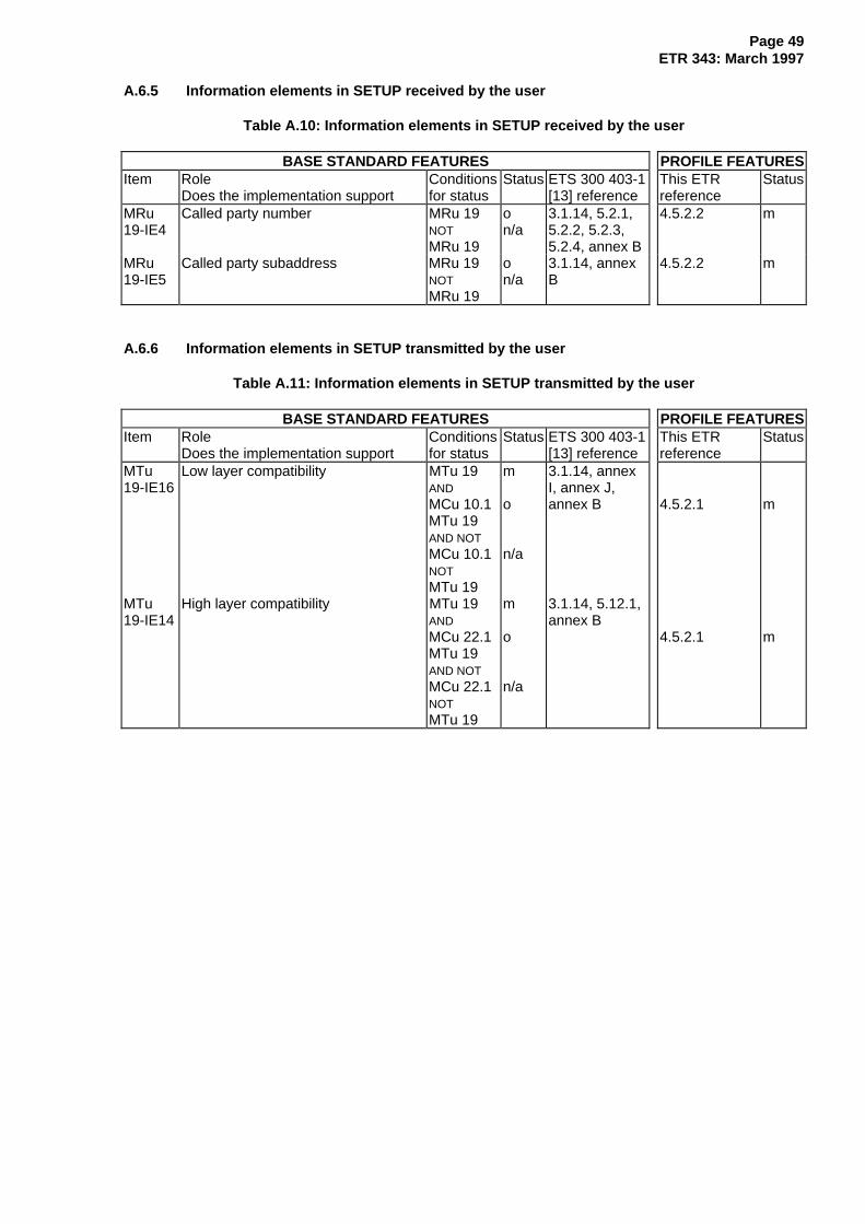
Page 49ETR 343: March 1997
A.6.5 Information elements in SETUP received by the user
Table A.10: Information elements in SETUP received by the user
BASE STANDARD FEATURES PROFILE FEATURESItem Role
Does the implementation supportConditionsfor status
Status ETS 300 403-1[13] reference
This ETRreference
Status
MRu19-IE4
Called party number MRu 19NOTMRu 19
on/a
3.1.14, 5.2.1,5.2.2, 5.2.3,5.2.4, annex B
4.5.2.2 m
MRu19-IE5
Called party subaddress MRu 19NOTMRu 19
on/a
3.1.14, annexB
4.5.2.2 m
A.6.6 Information elements in SETUP transmitted by the user
Table A.11: Information elements in SETUP transmitted by the user
BASE STANDARD FEATURES PROFILE FEATURESItem Role
Does the implementation supportConditionsfor status
Status ETS 300 403-1[13] reference
This ETRreference
Status
MTu19-IE16
Low layer compatibility MTu 19ANDMCu 10.1MTu 19AND NOTMCu 10.1NOTMTu 19
m
o
n/a
3.1.14, annexI, annex J,annex B 4.5.2.1 m
MTu19-IE14
High layer compatibility MTu 19ANDMCu 22.1MTu 19AND NOTMCu 22.1NOTMTu 19
m
o
n/a
3.1.14, 5.12.1,annex B
4.5.2.1 m

Page 50ETR 343: March 1997
A.6.7 Bearer capability
Table A.12: Bearer capability structure
BASE STANDARD FEATURES PROFILE FEATURESItem Role
Does the implementation supportConditionsfor status
Status ETS 300 403-1[13] reference
This ETRreference
Status
ISu 1.2 Octet 3 bits 1 to 5, informationtransfer capability
4.5.5 1, 4.5.2.1.1
1. Speech o x2. Unrestricted digital o m4. 3,1 kHz audio o x5. Unrestricted digital
information withtones/announcements
o x
ISu 1.3 Octet 4 bits 6 and 7, transfer mode1. Circuit o m2. Packet o x
ISu 1.4 Octet 4 bits 1 to 5, informationtransfer rate
1. 64 kbit/s o m6. Multirate o x
ISu 1.9 Octet 4.1 Rate multiplier o xISu 1.10 Octet 5 bits 1 to 5, user information
layer 1 protocolo x
ISu 1.11 Octet 5a bit 7,synchronous/asynchronous
o x
ISu 1.12 Octet 5a bit 6, negotiation indicator o xISu 1.13 Octet 5a bits 1 to 5, user rate o xISu 1.14 Octet 5b bits 6 and 7, intermediate
rateo x
ISu 1.15 Octet 5b bit 5, Network IndependentClock (NIC) on transmission
o x
ISu 1.16 Octet 5b bit 4, NIC on reception o xISu 1.17 Octet 5b bit 3, flow control on
transmissiono x
ISu 1.18 Octet 5b bit 2, flow control onreception
o x
ISu 1.25 Octet 5c bits 6 and 7, number of stopbits
o x
ISu 1.26 Octet 5c bits 4 and 5, number of databits excluding parity
o x
ISu 1.27 Octet 5c bits 1 to 3, parity information o xISu 1.28 Octet 5d bit 7, duplex mode o xISu 1.29 Octet 5d bits 1 to 6, modem type o xISu 1.30 Octet 6 bits 1 to 5, user information
layer 2 protocolo x
ISu 1.31 Octet 7 bits 1 to 5, user informationlayer 3 protocol
o x
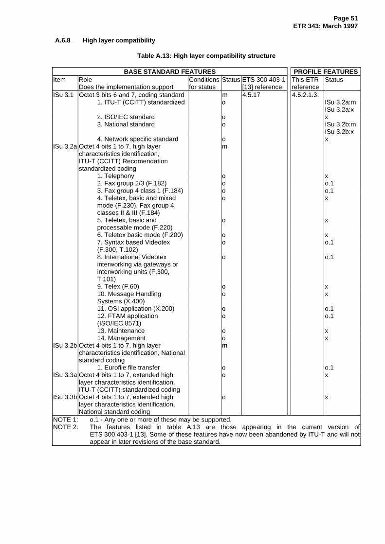
Page 51ETR 343: March 1997
A.6.8 High layer compatibility
Table A.13: High layer compatibility structure
BASE STANDARD FEATURES PROFILE FEATURESItem Role
Does the implementation supportConditionsfor status
Status ETS 300 403-1[13] reference
This ETRreference
Status
ISu 3.1 Octet 3 bits 6 and 7, coding standard m 4.5.17 4.5.2.1.31. ITU-T (CCITT) standardized o ISu 3.2a:m
ISu 3.2a:x2. ISO/IEC standard o x3. National standard o ISu 3.2b:m
ISu 3.2b:x4. Network specific standard o x
ISu 3.2a Octet 4 bits 1 to 7, high layercharacteristics identification,ITU-T (CCITT) Recomendationstandardized coding
m
1. Telephony o x2. Fax group 2/3 (F.182) o o.13. Fax group 4 class 1 (F.184) o o.14. Teletex, basic and mixed mode (F.230), Fax group 4, classes II & III (F.184)
o x
5. Teletex, basic and processable mode (F.220)
o x
6. Teletex basic mode (F.200) o x7. Syntax based Videotex (F.300, T.102)
o o.1
8. International Videotex interworking via gateways or interworking units (F.300, T.101)
o o.1
9. Telex (F.60) o x10. Message Handling Systems (X.400)
o x
11. OSI application (X.200) o o.112. FTAM application (ISO/IEC 8571)
o o.1
13. Maintenance o x14. Management o x
ISu 3.2b Octet 4 bits 1 to 7, high layercharacteristics identification, Nationalstandard coding
m
1. Eurofile file transfer o o.1ISu 3.3a Octet 4 bits 1 to 7, extended high
layer characteristics identification,ITU-T (CCITT) standardized coding
o x
ISu 3.3b Octet 4 bits 1 to 7, extended highlayer characteristics identification,National standard coding
o x
NOTE 1: o.1 - Any one or more of these may be supported.NOTE 2: The features listed in table A.13 are those appearing in the current version of
ETS 300 403-1 [13]. Some of these features have now been abandoned by ITU-T and will notappear in later revisions of the base standard.

Page 52ETR 343: March 1997
A.6.9 Low layer compatibility
Table A.14: Low layer compatibility structure
BASE STANDARD FEATURES PROFILE FEATURESItem Role
Does the implementation support...Conditionsfor status
Status ETS 300 403-1[13] reference
This ETRreference
Status
ISu 4.1 Octet 3 bits 6 and 7, coding standard 4.5.19 4.5.2.1.21. ITU-T standardized o m2. ISO/IEC standard o x3. National standard o x4. Network specific standard o x
ISu 4.2 Octet 3 bits 1 to 5, informationtransfer capability
1. Speech o x2. Unrestricted digital o m3. Restricted digital o x4. 3,1 kHz audio o x5. 7 kHz audio o x6. Video o x
ISu 4.3 Octet 3a bit 7, negotiation indicator o 4.5.2.3 m1. Outband negotiation notpossible
o o.1(note 2)
2. Outband negotiationpossible
o o
ISu 4.4 Octet 4 bits 6 and 7, transfer mode1. Circuit o m2. Packet o x
ISu 4.5 Octet 4 bits 1 to 5, informationtransfer rate
1. 64 kbit/s o m2. 2 x 64 kbit/s o x3. 384 kbit/s o x4. 1536 kbit/s o x5. 1920 kbit/s o x6. Multirate o x
ISu 4.10 Octet 4.1 Rate multiplier o xISu 4.11 Octet 5 bits 1 to 5, user information
layer 1 protocolo x
ISu 4.12 Octet 5a bit 7,synchronous/asynchronous
o x
ISu 4.13 Octet 5a bit 6, negotiation indicator o xISu 4.14 Octet 5a bits 1 to 5, user rate o xISu 4.15 Octet 5b bits 6 and 7, intermediate
rateo x
ISu 4.16 Octet 5b bit 5, NIC on transmission o xISu 4.17 Octet 5b bit 4, NIC on reception o xISu 4.18 Octet 5b bit 3, flow control on
transmissiono x
ISu 4.19 Octet 5b bit 2, flow control onreception
o x
ISu 4.20 Octet 5b bit 7, header o x
(continued)

Page 53ETR 343: March 1997
Table A.14 (continued): Low layer compatibility structure
BASE STANDARD FEATURES PROFILE FEATURESItem Role
Does the implementation support...Conditionsfor status
Status ETS 300 403-1[13] reference
This ETRreference
Status
ISu 4.21 Octet 5b bit 6, Multiple FrameEstablishment (MFE) support in datalink
o x
ISu 4.22 Octet 5b bit 5, mode of operation o xISu 4.23 Octet 5b bit 4, Logical Link Identifier
(LLI) negotiationo x
ISu 4.24 Octet 5b bit 3, assignor/assignee o xISu 4.25 Octet 5b bit 2, in-band/out-band
negotiationo x
ISu 4.26 Octet 5c bits 6 and 7, number of stopbits
o x
ISu 4.27 Octet 5c bits 4 and 5, number of databits excluding parity
o x
ISu 4.28 Octet 5c bits 1 to 3, parity information o xISu 4.29 Octet 5d bit 7, duplex mode o xISu 4.30 Octet 5d bits 1 to 6, modem type o xISu 4.31 Octet 6 bits 1 to 5, user information
layer 2 protocolo
1. Basic mode ISO 1745 (note 1) o x2. ITU-T Rec. Q.921 [11] o x3. ITU-T Rec. X.25 [4] link level o x4. ITU-T Rec. X.25 [4] multi-link o x5. Extended LAPB for halfduplex (ITU-T Rec.T.71)(note 1)
o x
6. HDLC ARM (ISO 4335 [16]) o x7. HDLC NRM (ISO 4335 [16]) o x8. HDLC ABM (ISO 4335 [16]) o x9. LAN LLC ISO 8802/2 (note 1) o x10. ITU-T Rec. X.75 [4] single link procedure
o x
11. ISO 7776 [17] DTE-DTEoperation
o m
ISu 4.31.1
Octet 6a, mode of operation ISu 4.31NOTISu 4.31
o
n/a
m
ISu 4.31.2
Octet 6b, window size (k) ISu 4.31NOTISu 4.31
o
n/a
m
(continued)

Page 54ETR 343: March 1997
Table A.14 (concluded): Low layer compatibility structure
BASE STANDARD FEATURES PROFILE FEATURESItem Role
Does the implementation upport...Conditionsfor status
Status ETS 300 403-1[13] reference
This ETRreference
Status
ISu 4.32
Octet 7 bits 1 to 5, user informationlayer 3 protocol
o
1. ITU-T Rec. Q.931 (note 1) o x2. ITU-T Rec. X.25 [4] packetlayer
o x
3. ISO 8208 [20] (ITU-TRec X.25 for DTE)
o m
4. ISO 8348 [21] (OSI connection oriented service)
o x
5. ISO 8473 (OSI) (note 1) connectionless service)
o x
6. ITU-T Rec. T.70 [3]minimum network layer
o x
ISu 4.32.1
Octet 7a, mode of operation ISu 4.32NOTISu 4.32
o
n/a
m
ISu 4.32.2
Octet 7b, default packet size ISu 4.32NOTISu 4.32
o
n/a
m
ISu 4.32.3
Octet 7c, packet window size ISu 4.32NOTISu 4.32
o
n/a
m
NOTE 1: See annex D.NOTE 2: o.1 mandatory if option 2 not provided.NOTE 3: ITU-T Rec. means ITU-T Recommendation.

Page 55ETR 343: March 1997
A.7 Tables for the network layer: B-channel
A.7.1 Requirements List for ISO/IEC 8208 [20]
Table A.15 identifies the tables of the PICS proforma in ISO/IEC 8208 [20], and indicates their relevanceto the profile described by this ETR. Tables A.16 to A.37 specify the restrictions imposed by this profile onthe permitted support answers.
Table A.15: ISO/IEC 8208 [20] PICS tables
Category of PICStable
Subclause numberin ISO/IEC 8208 [20]
Name of PICS table
Profile does notrestrict permittedsupport answers
C.6.1C.6.2C.6.3
C.6.7C.8.1C.8.2C.9.1C.9.2
Link layer interactionsGeneral packet formattingPacket layer functions independent of logicalchannelsInterrupt transferFacilities sent during call set-up and clearingFacilities received during call set-up and clearingRegistration-facilities sentRegistration-facilities received
Profile restrictspermitted supportanswers
C.5C.6.4.1C.6.4.2C.6.5C.6.6
C.6.8.1C.6.8.2C.6.8.3C.7.1
C.8.1.1C.8.1.2C.8.1.3C.8.2.1C.8.2.2C.8.2.3
C.8.2.4
C.9.1.1
C.9.1.2
C.9.2.1
C.9.2.2
C.10.1
C.10.3
General DTE characteristicsCall set-upCall clearingResetting of logical channelsError proceduresSending dataReceiving dataDelivery confirmationValues of cause and diagnostic code fieldsFacilities sent in CALL REQUEST packetsFacilities sent in CALL ACCEPT packetsFacilities sent in CLEAR REQUEST packetsFacilities received in INCOMING CALL packetsFacilities received in CALL CONNECT packetsFacilities received in CLEAR INDICATION packetsFacilities received in CLEAR CONFIRMATIONpacketsRegistration-facilities sent in REGISTRATIONREQUEST packetsRegistration-facilities sent in REGISTRATIONCONFIRMATION packetsRegistration-facilities received in REGISTRATIONCONFIRMATION packetsRegistration-facilities received in REGISTRATIONREQUEST packetsValues for flow control parameters and throughputclass, Virtual Call serviceTimers, Retransmission Counts and logicalchannel ranges
Tables not relevant tothis profile
C.7.2C.7.3C.7.4
C.10.2
Operation in an ITU-T Rec. X.25 [4] environmentOperation in an ITU-T Rec. X.25 [4] networkenvironmentTransient statesValues for flow control parameters and throughputclass, Permanent Virtual Circuit service
NOTE: ITU-T Rec. means ITU-T Recommendation.

Page 56ETR 343: March 1997
A.7.1.1 General DTE characteristics
Table A.16: General DTE characteristics
BASE STANDARD FEATURES PROFILE FEATURESItem Protocol feature ISO/IEC 8208
[20] ReferenceStatus This ETR
ReferenceStatus
Service supported: 4.6Vs - Virtual Call o.1 mVp - Permanent Virtual Circuit o.1 n/a
What environments are supported 3, 3.2 4.6Ec/8 - DTE/DCE (1988) o.2 4.6.1 iEc/4 - DTE/DCE (1984) o.2 4.6.1 iEc/0 - DTE/DCE (1980) o.2 4.6.1 iEt/t - DTE/DTE in fixed role as DTE o.2 4.6.2, 4.6.1 xEt/c - DTE/DTE in fixed role as DCE Vs:o.2 4.6.2, 4.6.1 xEt/d - DTE/DTE with dynamic role
selection4.5 Vs:o.2 4.6.1 m
What packet sequence numbering issupported
M8 - modulo 8 13.2, 12.1.1,table 3
o.3 4.6.4.3 m
M128 - modulo 128 (extended) 3.2, 12.1.1,table 3
o.3 4.6.4.3 o
Is the reference number optional userfacility supported
RNa - without reversion to use of logical channel ranges
13.28.2.1 Et:oEt:x
4.6.11 x
RNb - with possible reversion of operating mode to use logical channel ranges
13.28.2.1 Et:oEt:x
4.6.11 x
A.7.1.2 Call set-up
Table A.17: Call set-up
BASE STANDARD FEATURES PROFILE FEATURESItem Protocol feature ISO/IEC 8208
[20] ReferenceStatus This ETR
ReferenceStatus
Are incoming virtual calls supported: 5.2.2, 5.2.5,table 33
4.6.3.1
S2a - Fast select, acceptance possible 5.2.3, 13.17 o 4.6.10.2 mS2b - Fast select, always cleared 13.17 o 4.6.10.2 xS2c - Non fast select, with acceptance
possible5.2.3 o 4.6.3.1 m
S2d - Non fast select, always cleared 5.2.3 o 4.6.3.1 x
Is D-bit negotiation supported:DN1 - for outgoing virtual calls 6.3 S1ac:o 4.6.5 x
DN2 - for incoming virtual calls 6.3 S2ac:o 4.6.5 x

Page 57ETR 343: March 1997
A.7.1.3 Call clearing
Table A.18: Call clearing
BASE STANDARD FEATURES PROFILE FEATURESItem Protocol feature ISO/IEC 8208
[20] ReferenceStatus This ETR
ReferenceStatus
Is call clearing supported as: 5.5.4, table 33 4.6.3.1C1 - response to indication of clearing 5.5.2 o mC2a - aborting an outgoing virtual call
attempt5.4, 5.5.1 5.5.3 S1:o S1:m
C2c - originating clearing of an established virtual call
5.5.1, 5.5.3 o m
CP3b send CLEAR REQUEST, basicformat
12.2.3.1 Cbcxa:o.6 m
CP3e send CLEAR REQUEST, extendedformat
12.2.3.1,12.2.3.2
Cbcxa:o.6 m
A.7.1.4 Resetting of logical channels
Table A.19: Resetting of logical channels
BASE STANDARD FEATURES PROFILE FEATURESItem Protocol feature ISO/IEC 8208
[20] ReferenceStatus This ETR
ReferenceStatus
Is resetting supported: 8, 8.4, table 34 o 4.6.3.1RSi - as initiator 8.1, 8.3 o m
send RESET REQUEST 12.5.1 receive RESETINDICATION/CONFIRM
12.5.2, 12.5.1
RSr - as responder 8.2 o m receive RESET INDICATION 12.5.1 send RESET CONFIRMATION 12.5.2
A.7.1.5 Error procedures
Table A.20: Error procedures
BASE STANDARD FEATURES PROFILE FEATURESItem Protocol feature ISO/IEC 8208
[20] ReferenceStatus This ETR
ReferenceStatus
Is the ERROR-C procedure: 5.2.1, 5.4, 8.1,table 33
4.6.3.1
W1a - clear the virtual call o.7 mW1b - restart the packet layer o.7 x
Is the ERROR-R procedure for virtualcalls:
6.3, 6.4, 6.8.1,6.8.2, 7.1.3,7.1.4, 8.2,11.2.1, 13.4.1,tables 34-36
4.6.3.1
W2sc - restart the packet layer o.8 x

Page 58ETR 343: March 1997
A.7.1.6 Sending data
Table A.21: Sending data
BASE STANDARD FEATURES PROFILE FEATURESItem Protocol feature ISO/IEC 8208
[20] ReferenceStatus This ETR
ReferenceStatus
DS1 Is sending of DATA packetssupported:
6, 6.1, 6.2,7.1.1, 7.1.2,7.1.3, 12.3.1
o 4.6.3.1 m
DS2 - Send-window rotation on receiving updated P(R) values
7.1, 7.1.2,7.1.3
o 4.6.3.1 m
DS5a - Sending Q = 0 in DATA packets 6.6 o.10 4.6.7 Aq:o.2Aq:m(note)
DS5b - Sending Q = 1 in DATA packets 6.6 o.10 4.6.7 Aq:o.2Aq:x(note)
DS6 - Responding to packet retransmission requests (received REJECT packets)
13.4.2, 12.8 ET:o 4.6.9 x
DS7a - ERROR-R action on expiry 11.2.1(a) o xDS8 - Discard of overlength flow control
packets (instead of ERROR-R)table 36 note 2 o x
NOTE: Predicate Aq is defined in the profile specific ICS proforma, table B.10.o.2. At least one of these should be supported.

Page 59ETR 343: March 1997
A.7.1.7 Receiving data
Table A.22: Receiving data
BASE STANDARD FEATURES PROFILE FEATURESItem Protocol feature ISO/IEC 8208
[20] ReferenceStatus This ETR
ReferenceStatus
DR1 Receiving DATA packets: 6, 6.1, 6.2,7.1.1, 7.1.2,7.1.3, 12.3.1
o 4.6.3.1 m
DR2 - Receive-window rotation on receiving updated P(R) values
7.1, 7.1.2,7.1.3
o 4.6.3.1 m
DR3 - flow control by sending RECEIVE NOT READY and RECEIVE READY packets
7.1.5, 7.1.6,12.4.1, 12.4.2
o m
DR4b - Receiving M=1 in DATA packets 6.4, 6.5, 6.6,6.7
o 4.6.6 m
DR5a - Receiving Q=0 in DATA packets 6.6 o.11 4.6.7 Aq:o.3Aq:i
DR5b - Receiving Q=1 in DATA packets 6.6 o.11 4.6.7 Aq:o.3Aq:i
DR6 - Requesting packet retransmission by sending REJECT packets
13.4.1, 12.8 o 4.6.9 x
- Recovery from receipt of DATA packets containing invalid (PS), by:
DR7a - ERROR-R action 11.3(a) o.12 4.6.9 o.4DR7b - requesting packet retransmission 11.3(b) o.12 4.6.9 xDR7c - ignoring the packet and waiting for
correct retransmission of the packet11.3(c) o.12 4.6.9 o.4
- Recovery from receipt of DATA packets with invalid User Data field, by:
DR8a - ERROR-R action 11.3(a) o.13 4.6.9 o.5DR8b - requesting packet retransmission 11.3(b) o.13 4.6.9 xDR8c - ignoring the packet and waiting for
correct retransmission of the packet11.3(c) o.13 4.6.9 o.5
DR9 - Window status transmission timer procedure
11.2.2 o x
NOTE: Predicate Aq is defined in the profile specific ICS proforma, table B.10.o.3. At least one of these should be supported.o.4. At least one of these should be supported.o.5. At least one of these should be supported.
A.7.1.8 Delivery confirmation
Table A.23: Delivery confirmation
BASE STANDARD FEATURES PROFILE FEATURESItem Protocol feature ISO/IEC 8208
[20] ReferenceStatus This ETR
ReferenceStatus
DC Is Delivery Confirmation supported 6.3, 6.5, 6.7,7.1.4
o 4.6.5 x

Page 60ETR 343: March 1997
A.7.1.9 Values of cause and diagnostic code fields
Table A.24: Values of cause and diagnostic code fields
BASE STANDARD FEATURES PROFILE FEATURESItem Protocol feature ISO/IEC 8208
[20] ReferenceStatus This ETR
ReferenceStatus
Y1d - Cause = 128, private diagnostic codes
12.6.1.1,12.6.1.2, tables24-25
o.14 x
Y3a In Clear Request packets sendcause code = 0, specific codes
12.2.3.1.1,12.2.3.1.2,tables 24-25
o.15 m
Y3d - Cause = 128, private diagnostic codes
12.2.3.1.1,12.2.3.1.2,tables 24-25
o.15 x
Y5d - Cause = 128, private diagnostic codes
12.5.1.1,12.5.1.2, tables24-25
o.16 x

Page 61ETR 343: March 1997
A.7.1.10 Facilities sent in CALL REQUEST packets
Table A.25: Facilities sent in CALL REQUEST packets
BASE STANDARD FEATURES PROFILE FEATURESItem Protocol feature ISO/IEC 8208
[20] ReferenceStatus This ETR
ReferenceStatus
FS1pi Flow control Parameter Negotiation,packet size
13.12,15.2.2.1.1,
o 4.6.4.1 m
FS1wi Flow control Parameter Negotiation,window size
13.12,15.2.2.1.2
o 4.6.4.1 m
FS3b Closed User Group Selection, basicformat
13.14.6,15.2.2.3.1
o 4.6.10, 4.6.11 x
FS3e Closed User Group Selection,extended format
13.14.6,15.2.2.3.2
o 4.6.10, 4.6.11 x
FS4b Closed User Group With OutgoingAccess Selection, basic format
13.4.7,15.2.2.4.1
o 4.6.10, 4.6.11 x
FS4e Closed User Group With OutgoingAccess Selection, extended format
13.4.7,15.2.2.4.2
o 4.6.10, 4.6.11 x
FS5 Bilateral Closed User GroupSelection
13.15, 15.2.2.5 o 4.6.10, 4.6.11 x
FS6b Reverse charging 13.18, 13.19,15.2.2.6
o 4.6.10, 4.6.11 x
FS7i Network User Identification 13.21, 13.21.3,15.2.2.7
o 4.6.10, 4.6.11 x
FS8i Charging information, requestingservice
13.22,15.2.2.8.1
o 4.6.10, 4.6.11 x
FS9b RPOA selection, basic format 13.23, 13.23.2,15.2.2.9.1
o 4.6.10, 4.6.11 x
FS9e RPOA selection, extended format 13.23, 13.23.2,15.2.2.9.2
o 4.6.10, 4.6.11 x
FS99i Local non-ITU-T Rec. X.25 [4]facilities, following Facility Marker
15.1, table 16 o 4.6.10, 4.6.11 x
FS98i Remote non-ITU-T Rec. X.25 [4]facilities, following Facility Marker
15.1, table 16 o 4.6.10, 4.6.11 x
FS20i Facility Marker, ITU-T - specified DTEfacilities
15.1 o 4.6.10 fsi:mfsi:i
FS21i Calling Address Extension 14.1, 15.3.2.1 o 4.6.10, 4.6.11 xFS22i Called Address Extension 14.1, 15.3.2.2 o 4.6.10, 4.6.11 xFS26i Priority 14.5, 15.3.2.5 o 4.6.10, 4.6.11 xFS27i Protection 14.6, 15.3.2.6 o 4.6.10, 4.6.11 xNOTE 1: Predicate definition: fsi = FS23i OR FS24i OR FS25i.NOTE 2: ITU-T Rec. means ITU-T Recommendation.

Page 62ETR 343: March 1997
A.7.1.11 Facilities sent in CALL ACCEPT packets
Table A.26: Facilities sent in CALL ACCEPT packets
BASE STANDARD FEATURES PROFILE FEATURESItem Protocol feature ISO/IEC 8208
[20] ReferenceStatus This ETR
ReferenceStatus
FS1pr Flow control Parameter Negotiation,packet size
13.12,15.2.2.1.1,
o 4.6.4.1 m
FS1wr Flow control Parameter Negotiation,window size
13.12,15.2.2.1.2
o 4.6.4.1 m
FS7r Network User Identification 13.21, 13.21.3,15.2.2.7
o 4.6.10, 4.6.11 x
FS8r Charging information, requestingservice
13.22,15.2.2.8.1
o 4.6.10, 4.6.11 x
FS10r Called Line Address ModifiedNotification
13.26,15.2.2.12
o 4.6.10, 4.6.11 x
FS99r Local non - ITU-T Rec. X.25 [4]facilities, following Facility Marker
15.1, table 16 o 4.6.10, 4.6.11 x
FS98r Remote non - ITU-T Rec. X.25 [4]facilities, following Facility Marker
15.1, table 16 o 4.6.10, 4.6.11 x
FS20r Facility Marker, ITU-T - specified DTEfacilities
15.1 o 4.6.10 m
FS22r Called Address Extension 14.2, 15.3.2.2 o 4.6.10, 4.6.11 xFS24r End-to-End Transit Delay Negotiation 14.4, 15.3.2.4 o 4.6.10.5 mFS25r Expedited Data Negotiation 14.7, 15.3.2.7 o 4.6.10.6 mFS26r Priority 14.5, 15.3.2.5 o 4.6.10, 4.6.11 xFS27r Protection 14.6, 15.3.2.6 o 4.6.10, 4.6.11 xNOTE: ITU-T Rec. means ITU-T Recommendation.
A.7.1.12 Facilities sent in CLEAR REQUEST packets
Table A.27: Facilities sent in CLEAR REQUEST packets
BASE STANDARD FEATURES PROFILE FEATURESItem Protocol feature ISO/IEC 8208
[20] ReferenceStatus This ETR
ReferenceStatus
FS10d Called Line Address ModifiedNotification
13.26,15.2.2.12
o 4.6.10, 4.6.11 x
FS13 Call Deflection Selection 13.25.2.2,15.2.2.10
o 4.6.10, 4.6.11 x
FS99d Local non - ITU-T Rec. X.25 [4]facilities, following Facility Marker
15.1, table 16 o 4.6.10, 4.6.11 x
FS98d Remote non - ITU-T Rec. X.25 [4]facilities, following Facility Marker
15.1, table 16 o 4.6.10, 4.6.11 x
FS20d Facility Marker, ITU-T - specified DTEfacilities
15.1 o 4.6.10, 4.6.11 x
FS22d Called Address Extension 14.2, 15.3.2.2 o 4.6.10, 4.6.11 xFS21d Calling Address Extension 14.1, 15.3.2.1 o n/aFS23d Minimum Throughput Class
Negotiation14.3, 15.3.2.3 o n/a
FS24d End-to-End Transit Delay Negotiation 14.4, 15.3.2.4 o n/aFS25d Expedited Data Negotiation 14.7, 15.3.2.7 o n/aFS26d Priority 14.5, 15.3.2.5 o n/aFS27d Protection 14.6, 15.3.2.6 o n/aNOTE: ITU-T Rec. means ITU-T Recommendation.

Page 63ETR 343: March 1997
A.7.1.13 Facilities received in INCOMING CALL packets
Table A.28: Facilities received in INCOMING CALL packets
BASE STANDARD FEATURES PROFILE FEATURESItem Protocol feature ISO/IEC 8208
[20] ReferenceStatus This ETR
ReferenceStatus
FR1pi Flow control Parameter Negotiation,packet size
13.12,15.2.2.1.1
o 4.6.4.1 m
FR1wi Flow control Parameter Negotiation,window size
13.12,15.2.2.1.2
o 4.6.4.1 m
FR3b Closed User Group Selection, basicformat
13.14.6,15.2.2.3.1
o 4.6.10, 4.6.11 x
FR3e Closed User Group Selection,extended format
13.14.6,15.2.2.3.2
o 4.6.10, 4.6.11 x
FR4b Closed User Group With OutgoingAccess Selection, basic format
13.4.7,15.2.2.4.1
o 4.6.10, 4.6.11 x
FR4e Closed User Group With OutgoingAccess Selection, extended format
13.4.7,15.2.2.4.2
o 4.6.10, 4.6.11 x
FR5 Bilateral Closed User GroupSelection
13.15, 15.2.2.5 o 4.6.10, 4.6.11 x
FR6a Fast Select 13.16, 13.17,15.2.2.6,
o 4.6.10.2 m
FR6b Reverse charging 13.18, 13.19,15.2.2.6
o 4.6.10, 4.6.11 x
FR11 Call Redirection or Call DeflectionNotification
13.25.3,15.2.2.11
o 4.6.10, 4.6.11 x
FR12 Transit Delay Selection and Indication 13.27,15.2.2.13,
o 4.6.10.3 m
FR99i Local non-ITU-T Rec. X.25 [4]facilities, following Facility Marker
15.1, table 16 o 4.6.10, 4.6.11 x
FR20i Facility Marker, ITU-T - specified DTEfacilities
15.1 o 4.6.10 m
FR21 Calling Address Extension 14.1, 15.3.2.1 o 4.6.10, 4.6.11 xFR22i Called Address Extension 14.2, 15.3.2.2 o 4.6.10, 4.6.11 xFR23 Minimum Throughput Class
Negotiation14.3, 15.3.2.3 o 4.6.10.4 m
FR24i End-to-End Transit Delay Negotiation 14.4, 15.3.2.4 o 4.6.10.5 mFR25i Expedited Data Negotiation 14.7, 15.3.2.7 o 4.6.10.6 mFR26i Priority 14.5, 15.3.2.5 o 4.6.10, 4.6.11 xFR27i Protection 14.6, 15.3.2.6 o 4.6.10, 4.6.11 xNOTE: ITU-T Rec. means ITU-T Recommendation.

Page 64ETR 343: March 1997
A.7.1.14 Facilities received in call connect packets
Table A.29: Facilities received in call connect packets
BASE STANDARD FEATURES PROFILE FEATURESItem Protocol feature ISO/IEC 8208
[20] ReferenceStatus This ETR
ReferenceStatus
FR1pr Flow control Parameter Negotiation,packet size
13.12,15.2.2.1.1,
o 4.6.4.1 m
FR1wr Flow control Parameter Negotiation,window size
13.12,15.2.2.1.2
o 4.6.4.1 m
FR10r Called Line Address ModifiedNotification
13.26,15.2.2.12
o 4.6.10, 4.6.11 x
FR12r Transit Delay Selection and Indication 13.27,15.2.2.613,
o 4.6.10.3 m
FR99r Local non - ITU-T Rec. X.25 [4]facilities, following Facility Marker
15.1, table 16 o 4.6.10, 4.6.11 x
FR20r Facility Marker, ITU-T - specified DTEfacilities
15.1 o 4.6.10 m
FR22r Called Address Extension 14.2, 15.3.2.2 o 4.6.10, 4.6.11 xFR24r End-to-End Transit Delay Negotiation 14.4, 15.3.2.4 o 4.6.10.5 mFR26r Priority 14.5, 15.3.2.5 o 4.6.10, 4.6.11 xFR27r Protection 14.6, 15.3.2.6 o 4.6.10, 4.6.11 xNOTE: ITU-T Rec. means ITU-T Recommendation
A.7.1.15 Facilities received in clear indication packets
Table A.30: Facilities received in clear indication packets
BASE STANDARD FEATURES PROFILE FEATURESItem Protocol feature ISO/IEC 8208
[20] ReferenceStatus This ETR
ReferenceStatus
FR8ad Charging Information, monetary unit 13.22,15.22.8.2
o 4.6.10, 4.6.11 x
FR8bd Charging Information, segment count 13.22,15.22.8.3
o 4.6.10, 4.6.11 x
FR8cd Charging Information, call duration 13.22,15.22.8.4
o 4.6.10, 4.6.11 x
FR10d Called Line Address ModifiedNotification
13.26,15.2.2.12
o 4.6.10, 4.6.11 x
FR99d Local non - ITU-T Rec. X.25 [4]facilities, following Facility Marker
15.1, table 16 o 4.6.10, 4.6.11 x
FR20d Facility Marker, ITU-T - specified DTEfacilities
15.1 o n/a
FR22d Called Address Extension 14.2, 15.3.2.2 o 4.6.10, 4.6.11 xNOTE: ITU-T Rec. means ITU-T Recommendation.

Page 65ETR 343: March 1997
A.7.1.16 Facilities received in CLEAR CONFIRMATION packets
Table A.31: Facilities received in CLEAR CONFIRMATION packets
BASE STANDARD FEATURES PROFILE FEATURESItem Protocol feature ISO/IEC 8208
[20] ReferenceStatus This ETR
ReferenceStatus
FR8af Charging Information, monetary unit 13.22,15.22.8.2
o 4.6.10, 4.6.11 x
FR8bf Charging Information, segment count 13.22,15.22.8.3
o 4.6.10, 4.6.11 x
FR8cf Charging Information, call duration 13.22,15.22.8.4
o 4.6.10, 4.6.11 x
A.7.1.17 Registration-facilities sent in REGISTRATION REQUEST packets
Table A.32: Registration-facilities sent in REGISTRATION REQUEST packets
BASE STANDARD FEATURES PROFILE FEATURESItem Protocol feature ISO/IEC 8208
[20] ReferenceStatus This ETR
ReferenceStatus
Invocation indicated: 16.2.2.3GS3ia - Incoming Calls Barred o 4.6.11 xGS3ib - Outgoing Calls Barred o 4.6.11 xGS3ic - Fast Select Acceptance o 4.6.11 xGS3id - Reverse Charging Acceptance o 4.6.11 xGS3ig - Charging Information per Interface o 4.6.11 x
GS4i Facilities That May Be NegotiatedOnly When All Logical ChannelsUsed For Virtual Calls Are In State p1Registration-Facility
16.2.2.4 4.6.11 x
Invocation indicated: 16.2.2.4GS4ia Extended Packet Sequence
Numberingo 4.6.11 x
GS4ib - Packet Retransmission o 4.6.11 x
GS5i Non-standard Default Packet SizesRegistration-Facility
16.2.2.5 o 4.6.11 x
GS6i Non-standard Default Window SizesRegistration-Facility
16.2.2.6 o 4.6.11 x
GS7i Default Throughput ClassesAssignment Registration-Facility
16.2.2.7,table 23
o 4.6.11 x
GS8i Logical Channel Types RangesRegistration-Facility
16.2.2.8 o 4.6.11 x

Page 66ETR 343: March 1997
A.7.1.18 Registration-facilities sent in registration confirmation packets
Table A.33: Registration-facilities sent in registration confirmation packets
BASE STANDARD FEATURES PROFILE FEATURESItem Protocol feature ISO/IEC 8208
[20] ReferenceStatus This ETR
ReferenceStatus
Availability indicated: 16.2.2.2GS2ra - Extended Packet Sequence
Numberingo 4.6.11 x
GS2rb - Packet Retransmission o 4.6.11 xGS2ri - Default Throughput Classes
AssignmentRegistration-Facility
o 4.6.11 x
GS2rj - Non-standard Default Window Sizes Registration-Facility
o 4.6.11 x
GS2rk - Non-standard Default Packet Sizes Registration-Facility
o 4.6.11 x
Invocation indicated: 16.2.2.3GS3ra - Incoming Calls Barred o 4.6.11 xGS3rb - Outgoing Calls Barred o 4.6.11 xGS3rc - Fast Select Acceptance o 4.6.11 x
GS4r Facilities That May Be NegotiatedOnly When All Logical ChannelsUsed For Virtual Calls Are In State p1Registration-Facility
16.2.2.4 4.6.11 x
Invocation indicated: 16.2.2.4GS4ra - Extended Packet Sequence
Numberingo 4.6.11 x
GS4rb - Packet Retransmission o 4.6.11 x
GS5r Non-standard Default Packet SizesRegistration-Facility
16.2.2.5 o 4.6.11 x
GS6r Non-standard Default Window SizesRegistration-Facility
16.2.2.6 o 4.6.11 x
GS7r Default Throughput ClassesAssignment Registration-Facility
16.2.2.7,table 23
o 4.6.11 x
GS8r Logical Channel Types RangesRegistration-Facility
16.2.2.8 o 4.6.11 x
A.7.1.19 Registration-facilities received in registration confirmation packets
Table A.34: Registration-facilities received in registration confirmation packets
BASE STANDARD FEATURES PROFILE FEATURESItem Protocol feature ISO/IEC 8208
[20] ReferenceStatus This ETR
ReferenceStatus
GR5i Non-standard Default Packet SizesRegistration-Facility
16.2.2.5 GS5i:m 4.6.11 x
GR6i Non-standard Default Window SizesRegistration-Facility
16.2.2.6 GS6i:m 4.6.11 x
GR7i Default Throughput ClassesAssignment Registration-Facility
16.2.2.7,table 23
GS7i:m 4.6.11 x
GR8i Logical Channel Types RangesRegistration-Facility
16.2.2.8 GS8i:m 4.6.11 x

Page 67ETR 343: March 1997
A.7.1.20 Registration-facilities received in registration request packets
Table A.35: Registration-facilities received in registration request packets
BASE STANDARD FEATURES PROFILE FEATURESItem Protocol feature ISO/IEC 8208
[20] ReferenceStatus This ETR
ReferenceStatus
GR5r Non-standard Default Packet SizesRegistration-Facility
16.2.2.5 o 4.6.11 x
GR6r Non-standard Default Window SizesRegistration-Facility
16.2.2.6 o 4.6.11 x
GR7r Default Throughput ClassesAssignment Registration-Facility
16.2.2.7,table 23
o 4.6.11 x
GR8r Logical Channel Types RangesRegistration-Facility
16.2.2.8 o 4.6.11 x
A.7.1.21 Values for flow control parameters, etc.
Table A.36: Values for flow control parameters, etc.
BASE STANDARD FEATURES PROFILE FEATURESItem Protocol feature ISO/IEC 8208
[20] ReferenceStatus This ETR
ReferenceStatus(note)
What values are supported for:V1s - Default packet sizes, sending
(octets)16.2.2.5 4.6.4.2 128
V1r - Default packet sizes, receiving (octets)
16.2.2.5 4.6.4.2 128
V2s - Default window sizes, sending (octets)
16.2.2.6 4.6.4.3 2
V2r - Default window sizes, receiving (octets)
16.2.2.6 4.6.4.3 2
V3s - Default throughput classes, sending (bits/second)
16.2.2.7,table 23
4.6.8 64 000
V3r - Default throughput classes, receiving (bits/second)
16.2.2.7,table 23
4.6.8 64 000
V5 Can different default packet sizes beset for sending and receiving
13.9 o 4.6.4.2 n/a
V7 Can different default window sizes beset for sending and receiving
13.10 o 4.6.4.2 n/a
V8 Can different default throughputclasses be set for sending andreceiving
13.11 o 4.6.8 n/a
V9s - packet sizes negotiable, sending(octets)
15.2.2.1.1 4.6.4.2 128,256,512,1 024,2 048
V9r - packet sizes negotiable, receiving(octets)
15.2.2.1.1 4.6.4.2 128,256,512,1 024,2 048
NOTE: A numeric value(s) indicates the permitted support answer(s).

Page 68ETR 343: March 1997
A.7.1.22 Timers, Retransmission Counts and logical channel ranges
Table A.37: Timers, Retransmission Counts and logical channel ranges
BASE STANDARD FEATURES PROFILE FEATURESItem Protocol feature ISO/IEC 8208
[20] ReferenceStatus This ETR
ReferenceStatus(note)
Logical Channel Range Parameters 16.2.2.8, fig. 1 4.6.2LC1 LIC 13.8 LCb:0LC2 HIC 13.8 LCb:0LC3 LTC LCb:1LC4 HTC LCb:1LC5 LOC 13.7 LCb:0LC6 HOC 13.7 LCb:0LC8 Maximum number of logical channels
for Virtual CallsLCb:1
NOTE: These numeric values indicate the permitted support answers for the default case.Predicate LCb is defined in the profile specific ICS proforma, table B.10.
A.7.2 Requirements List for ISO/IEC 8878 [22]
Table A.38 identifies the tables of the PICS proforma in ISO/IEC 8878 [22] and indicates their relevance tothe profile described by this ETR. Tables A.39 to A.44 specify the restrictions imposed by this profile onthe permitted support answers.
Table A.38: ISO/IEC 8878 [22]PICS tables
Category of PICStable
Subclause numberin ISO/IEC 8878 [22]
Name of PICS table
Profile does notrestrict permittedsupport answers
D.6.6.2.4D.6.6.2.3D.6.6.2.6
Data packet with Q-bit set to 1Zero-length M-bit SequenceFacilities missing in a CALL CONNECTED packet
Profile restrictspermitted supportanswers
D.6.5D.6.6.1
D.6.6.2.1D.6.6.2.2D.6.6.2.5
Major capabilitiesNetwork Address mappingInterrupt packetData packet with D-bit set to 1Facilities missing in an INCOMING CALL packet
Tables not relevant tothis profile
D.6.7D.6.8
Questions related to 1980 SNDCPQuestions applicable for PVC SNDCP
A.7.2.1 Major capabilities
Table A.39: Major capabilities
BASE STANDARD FEATURES PROFILE FEATURESItem Protocol feature ISO/IEC 8878
[22] ReferenceStatus This ETR
ReferenceStatus
SY1 ITU-T Rec. X.25 [4]/PLP 1984 VCprocedures
clauses 0 - 12 o.1 4.7.1 m
SY2 ITU-T Rec. X.25 [4]/PLP 1980 VCprocedures
annex A o.1 4.7.1 x
SY4 PVC SNDCP procedures annex F o 4.7.1 x
ED The system supports Expedited Datatransfer
6.2.4, 10 EDT:o 4.7.3.2.6 m
RC The system supports NetworkReceive Confirmation
6.2.3, 8.2.3, 9 o 4.6.5 x
NOTE: ITUT-T Rec. means ITU-T Recommendation.

Page 69ETR 343: March 1997
A.7.2.2 Network Address mapping
Table A.40: Network Address mapping
BASE STANDARD FEATURES PROFILE FEATURESItem Protocol feature ISO/IEC 8878
[22] ReferenceStatus This ETR
ReferenceStatus
Called Network Address:AFb Can the system encode the address
in the AF without the AEF or AEP6.2.2.1.1 OC:o 4.7.3.1 m
AFe Can the system decode the addressin the AF without the AEF or AEP
6.2.2.2.1 IC:o 4.7.3.1 m
Calling Network Address:AFa Can the system encode the address
in the AF without the AEF or AEP6.2.2.1.1 OC:o 4.7.3.1 m
AFd Can the system decode the addressin the AF without the AEF or AEP
6.2.2.2.1 IC:o 4.7.3.1 m
Responding Network Address:AFf Can the system encode the address
in the AF without the AEF or AEP6.2.2.1.1 OC:o 4.7.3.1 m
AFc Can the system decode the addressin the AF without the AEF or AEP
6.2.2.2.1 IC:o 4.7.3.1 m
A.7.2.3 Interrupt packet
Table A.41: Interrupt packet
BASE STANDARD FEATURES PROFILE FEATURESItem Protocol feature ISO/IEC 8878
[22] ReferenceStatus This ETR
ReferenceStatus
MV1c Other 12 o.6 4.6.10.6 m
A.7.2.4 Data packet with D-bit set to 1
Table A.42: Data packet with D-bit set to 1
BASE STANDARD FEATURES PROFILE FEATURESItem Protocol feature ISO/IEC 8878
[22] ReferenceStatus This ETR
ReferenceStatus
MV2c Other 12 o.7 4.6.5 m
A.7.2.5 Facilities missing in an INCOMING CALL packet
Table A.43: Facilities missing in an INCOMING CALL packet
BASE STANDARD FEATURES PROFILE FEATURESItem Protocol feature ISO/IEC 8878
[22] ReferenceStatus This ETR
ReferenceStatus
MV5a If an Incoming Call packet is receivedwithout the Fast Select facility, thesystem clears the NC and indicates adiagnostic code of 228 (or 224).
12 o.10 4.7.3.2.2,4.7.3.3
x
MV6a If an Incoming Call packet is receivedwithout the TCN facility, the systemclears the NC and indicates adiagnostic code of 228 (or 224).
12 o.10 4.7.3.2.2,4.7.3.3
x

Page 70ETR 343: March 1997
A.7.2.6 Restrictions on ISO/IEC 8208 [20] requirements
Subclause D.7.1 of ISO/IEC 8878 [22] contains modifications to the permitted support answers for thePICS proforma in ISO/IEC 8208 [20] for TEs claiming compliance with the CONS. Table A.44 below isbased on these modifications, and should be used in addition to the tables contained insubclauses A.7.1.1 to A.7.1.22 above.
Table A.44: Restrictions on ISO/IEC 8208 [20] requirements
BASE STANDARD FEATURES PROFILE FEATURESItem Protocol feature ISO/IEC 8208
[20] ReferenceStatus This ETR
ReferenceStatus
Are outgoing calls supported:S1a - fast select, no restriction on
response5.2.4, 13.16 o 4.7.3.2.2 OC:m
SP1e sends CALL REQUEST, extendedformat
12.2.1.1,12.2.1.2
S1ab:o.4 4.7.3 OC:m
Are incoming calls supported:S2a - fast select, acceptance possible 5.2.3, 13.17 o 4.7.3.2.2 IC:mS2b - fast select, always cleared 13.17 o 4.7.3.2.2 IC:xSP4b send CALL ACCEPTED, basic format 12.2.2.1,
12.2.2.2o 4.7.3 IC:m
SP4e send CALL ACCEPTED, extendedformat
12.2.2.1,12.2.2.2
S2axc:o.5S2anc:o
4.7.3 IC:m
Is D-bit negotiation supported:DN1 - for outgoing calls 6.3 S1ac:o 4.7.3 OC:mDN2 - for incoming calls 6.3 S2ac:o 4.7.3 IC:m
(continued)
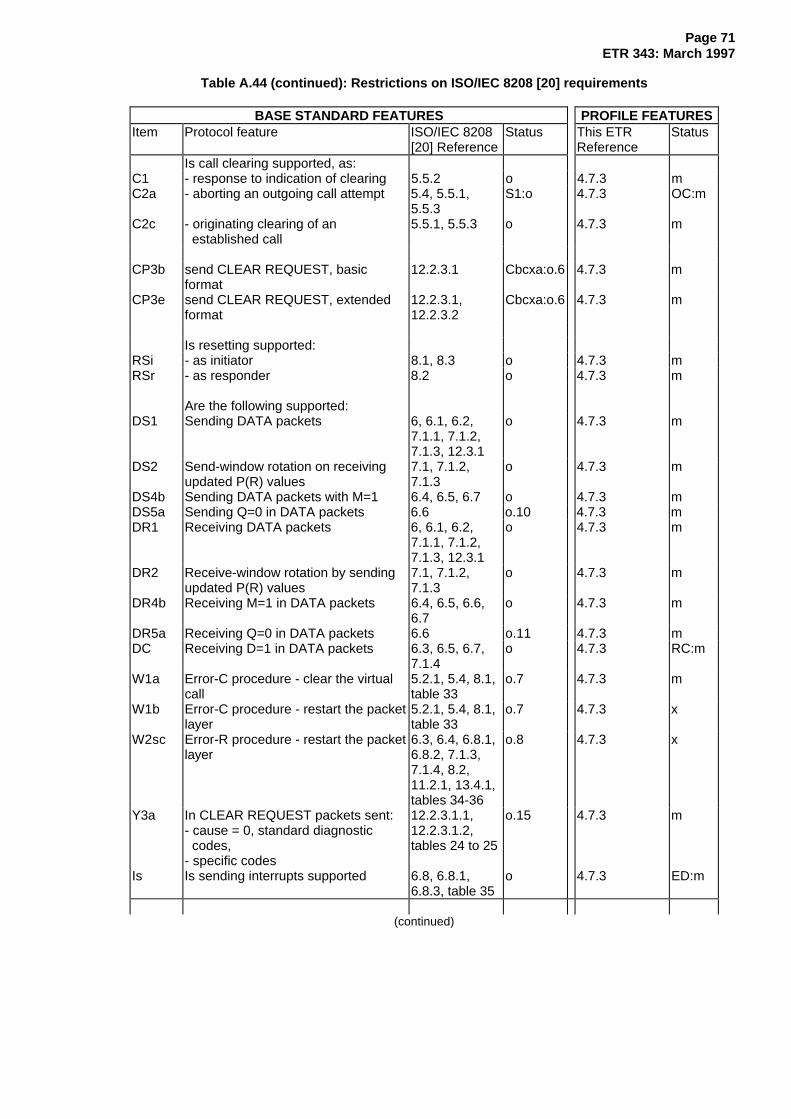
Page 71ETR 343: March 1997
Table A.44 (continued): Restrictions on ISO/IEC 8208 [20] requirements
BASE STANDARD FEATURES PROFILE FEATURESItem Protocol feature ISO/IEC 8208
[20] ReferenceStatus This ETR
ReferenceStatus
Is call clearing supported, as:C1 - response to indication of clearing 5.5.2 o 4.7.3 mC2a - aborting an outgoing call attempt 5.4, 5.5.1,
5.5.3S1:o 4.7.3 OC:m
C2c - originating clearing of an established call
5.5.1, 5.5.3 o 4.7.3 m
CP3b send CLEAR REQUEST, basicformat
12.2.3.1 Cbcxa:o.6 4.7.3 m
CP3e send CLEAR REQUEST, extendedformat
12.2.3.1,12.2.3.2
Cbcxa:o.6 4.7.3 m
Is resetting supported:RSi - as initiator 8.1, 8.3 o 4.7.3 mRSr - as responder 8.2 o 4.7.3 m
Are the following supported:DS1 Sending DATA packets 6, 6.1, 6.2,
7.1.1, 7.1.2,7.1.3, 12.3.1
o 4.7.3 m
DS2 Send-window rotation on receivingupdated P(R) values
7.1, 7.1.2,7.1.3
o 4.7.3 m
DS4b Sending DATA packets with M=1 6.4, 6.5, 6.7 o 4.7.3 mDS5a Sending Q=0 in DATA packets 6.6 o.10 4.7.3 mDR1 Receiving DATA packets 6, 6.1, 6.2,
7.1.1, 7.1.2,7.1.3, 12.3.1
o 4.7.3 m
DR2 Receive-window rotation by sendingupdated P(R) values
7.1, 7.1.2,7.1.3
o 4.7.3 m
DR4b Receiving M=1 in DATA packets 6.4, 6.5, 6.6,6.7
o 4.7.3 m
DR5a Receiving Q=0 in DATA packets 6.6 o.11 4.7.3 mDC Receiving D=1 in DATA packets 6.3, 6.5, 6.7,
7.1.4o 4.7.3 RC:m
W1a Error-C procedure - clear the virtualcall
5.2.1, 5.4, 8.1,table 33
o.7 4.7.3 m
W1b Error-C procedure - restart the packetlayer
5.2.1, 5.4, 8.1,table 33
o.7 4.7.3 x
W2sc Error-R procedure - restart the packetlayer
6.3, 6.4, 6.8.1,6.8.2, 7.1.3,7.1.4, 8.2,11.2.1, 13.4.1,tables 34-36
o.8 4.7.3 x
Y3a In CLEAR REQUEST packets sent:- cause = 0, standard diagnostic codes,- specific codes
12.2.3.1.1,12.2.3.1.2,tables 24 to 25
o.15 4.7.3 m
Is Is sending interrupts supported 6.8, 6.8.1,6.8.3, table 35
o 4.7.3 ED:m
(continued)

Page 72ETR 343: March 1997
Table A.44 (continued): Restrictions on ISO/IEC 8208 [20] requirements
BASE STANDARD FEATURES PROFILE FEATURESItem Protocol feature ISO/IEC 8208
[20] ReferenceStatus This ETR
ReferenceStatus
Ir Is receiving interrupts supported 6.8, 6.8.2,6.8.3, table 35
o 4.7.3 ED:m
Facilities sent in CALL REQUESTpackets
FS2i Throughput class negotiation 13.13,15.2.2.2, table18
o 4.7.3.2.1 OC:m
FS6a Fast select 13.16, 15.2.2.6 o 4.7.3.2.2 OC:mFS12 Transit delay selection and indication 13.27,
15.2.2.13o 4.7.3.2.3 OC:m
FS20i Facility marker for ITU-T - specifiedDTE facilities
15.1 o 4.7.3.2 OC:m
FS21i Calling address extension 14.1, 15.3.2.1 o 4.7.3.1 OC:mFS22i Called address extension 14.1, 15.3.2.2 o 4.7.3.1 OC:mFS23i Minimum throughput class
negotiation14.3, 15.3.2.2 o 4.7.3.2.4 OC:m
FS24i End-to-end transit delay negotiation 14.4, 15.3.2.4 o 4.7.3.2.5 OC:mFS25i Expedited data negotiation 14.7, 15.3.2.7 o 4.7.3.2.6 OC:ED
:mFS26i Priority 14.5, 15.3.2.5 o 4.7.3 OC:m
Facilities sent in CALL ACCEPTEDpackets
FS20r Facility marker for ITU-T - specifiedDTE facilities
15.1 IC:m
FS22r Called address extension 14.2, 15.3.2.2 o 4.7.3.1 IC:mFS24r End-to-end transit delay negotiation 14.4, 15.3.2.4 o 4.7.3.2.5 IC:mFS25r Expedited data negotiation 14.7, 15.3.2.7 o 4.7.3.2.6 IC:ED::
mFS26r Priority 14.5, 15.3.2.5 o 4.7.3 IC:m
Facilities sent in CLEAR REQUESTpackets
FS20d Facility marker for ITU-T - specifiedDTE facilities
15.1 o 4.7.3.2 IC:m
FS22d Called address extension 14.2, 15.3.2.2 o 4.7.3.1 IC:m
Facilities received in CALLCONNECTED packets
FR2r Throughput class negotiation 13.13,15.2.2.2, table18
o 4.7.3.2.1 OC:m
FR12r Transit delay selection and indication 13.27,15.2.2.13
o 4.7.3.2.3 OC:m
FR20r Facility marker for ITU-T - specifiedDTE facilities
15.1 o 4.7.3.2 OC:m
FR22r Called address extension 14.2, 15.3.2.2 o 4.7.3.1 OC:mFR24r End-to-end transit delay negotiation 14.4, 15.3.2.4 o 4.7.3.2.5 OC:mFR25r Expedited data negotiation 14.7, 15.3.2.7 o 4.7.3.2.6 OC:mFR26r Priority 14.5, 15.3.2.5 o 4.7.3 OC:m
Facilities received in INCOMINGCALL packets
(continued)

Page 73ETR 343: March 1997
Table A.44 (concluded): Restrictions on ISO/IEC 8208 [20] requirements
BASE STANDARD FEATURES PROFILE FEATURESItem Protocol feature ISO/IEC 8208
[20] ReferenceStatus This ETR
ReferenceStatus
FR2i Throughput class negotiation 13.13,15.2.2.2, table18
o 4.7.3.2.1 IC:m
FR6a Fast select 13.16, 13.17,15.2.2.6
o 4.7.3.2.2 IC:m
FR12I Transit delay selection and indication 13.27,15.2.2.13
o 4.7.3.2.3 IC:m
FR20i Facility marker for ITU-T - specifiedDTE facilities
15.1 o 4.7.3.2 IC:m
FR21 Calling address extension 14.1, 15.3.2.1 o 4.7.3.1 IC:mFR22i Called address extension 14.2, 15.3.2.2 o 4.7.3.1 IC:mFR23 Minimum throughput class
negotiation14.3, 15.3.2.3 o 4.7.3.2.4 IC:m
FR24i End-to-end transit delay negotiation 14.4, 15.3.2.4 o 4.7.3.2.5 IC:mFR25i Expedited data negotiation 14.7, 15.3.2.7 o 4.7.3.2.6 IC:mFR26i Priority 14.5, 15.3.2.5 o 4.7.3 IC:m
Facilities sent in CALL ACCEPTEDpackets
FS2r Throughput class negotiation 13.13,15.2.2.2, table18
o 4.7.3.2.1 IC:m
Facilities received in CLEARINDICATION packets
FR20d Facility marker for ITU-T - specifiedDTE facilities
15.1 o 4.7.3.2 OC:m
FR22d Called address extension 14.2, 15.3.2.2 o 4.7.3.1 OC:mNOTE: OC = Outgoing Calls; IC = Incoming Calls
A.8 Tables for the transport layer: B-channel
A.8.1 Requirements List for ITU-T Recommendation T.70 [3]
Since no PICS proforma exists for ITU-T Recommendation T.70 [3], no RL is necessary. The profilespecific ICS in annex B covers the specific usage of ITU-T Recommendation T.70 [3] according to therequirements of this ETR.
A.8.2 Requirements List for ISO/IEC 8073 [19]
Table A.45 identifies the tables of the PICS proforma in ISO/IEC 8073 [19] and indicates their relevance tothe profile described by this ETR. Tables A.46 to A.52 specify the restrictions imposed by this profile onthe permitted support answers.

Page 74ETR 343: March 1997
Table A.45: ISO/IEC 8073 [19] PICS tables
Category of PICStable
Subclause numberin ISO/IEC 8073 [19]
Name of PICS table
Profile does notrestrict permittedsupport answers
C.6.1C.7C.8
C.9.1C.9.3C.10
C.11.1C.11.5C.12.1C.13C.14C.15
annex B - NCMSNCMS functionsInitiator/responder capability for protocol classes0 to 4Supported functions for Class 0Supported functions for Class 2Supported TPDUsSupported parameters for NCMS - NCM TPDUSupported parameters for class 2 TPDUsSupported parameters for received TPDUs - NCMTPDUUser data in issued TPDUs (relevant classes)User data in received TPDUsAll tables in C.15, except C.15.1 and C.15.2
Profile restrictspermitted supportanswers
C.6.2C.11.2C.11.3C.15.1C.15.2C.16.1C.17
Classes implementedParameter values for CR TPDUSupported parameters for class 0 TPDUsClass negotiation - initiatorClass negotiation - responderAction on receipt of a protocol errorTimers and protocol parameters
Tables not relevant tothis profile
C.9.2, C.9.4, C.9.5C.11.4, C.11.6,
C.11.7C.12.2
Supported functions for other classesSupported parameters for other classesTPDUs in class 4
A.8.2.1 Classes implemented
Table A.46: Classes implemented
BASE STANDARD FEATURES PROFILE FEATURESItem Feature ISO/IEC 8073
[19] ReferenceStatus This ETR
ReferenceStatus
C0 Class 0 14 ISO:o.1CCT:m
4.8.3.2 m
C1 Class 1 14 C0:o 4.8.3.2 xC2 Class 2 14 ISO:o.1
CCT:o4.8.3.2 o
C3 Class 3 14 C2:o 4.8.3.2 xC4 Class 4 operation over CONS 14 C2:o 4.8.3.2 xC4L Class 4 operation over CLNS 14 ISO:C2:o
CCT:N/A4.8.3.2 x
A.8.2.2 Parameter values for CR TPDU
Table A.47: Parameter values for CR TPDU
BASE STANDARD FEATURES PROFILE FEATURESItem Feature ISO/IEC 8073
[19] ReferenceStatus This ETR
ReferenceStatus
ICR2 Is class 0 always offered as analternative class
14.4 oCCT:M
4.8.3.2 m

Page 75ETR 343: March 1997
A.8.2.3 Supported parameters for class 0 TPDUs
Table A.48: Supported parameters for class 0 TPDUs
BASE STANDARD FEATURES PROFILE FEATURESItem Feature ISO/IEC 8073
[19] ReferenceStatus This ETR
ReferenceStatus
I0CR6 Called Transport-Selector 13.3.4 a) o 4.8.3.5 mI0CR7 Calling Transport-Selector 13.3.4 a) o 4.8.3.5 m
A.8.2.4 Class negotiation - initiator
Table A.49: Class negotiation - initiator
BASE STANDARD FEATURES PROFILE FEATURESItem Protocol feature ISO/IEC 8073
[19] ReferenceAllowed This ETR
ReferenceAllowed
NAC2 Alternative class parameter if Class 2is preferred class
6.5.4 None,0, 2.
4.8.3.2 0
A.8.2.5 Class negotiation - responder
Table A.50: Class negotiation - responder
BASE STANDARD FEATURES PROFILE FEATURESItem Protocol feature ISO/IEC 8073
[19] ReferenceAllowed This ETR
ReferenceAllowed
RC2a Negotiation to alternative class inresponse to CR TPDU
6.5.4Table 3
0, 2 orconnectionrefused
4.8.3.2 0
A.8.2.6 Action on receipt of a protocol error
Table A.51: Action on receipt of a protocol error
BASE STANDARD FEATURES PROFILE FEATURESItem Feature ISO/IEC 8073
[19] ReferenceAllowedaction
This ETRReference
Allowedaction
PE0 Treatment of protocol error 6.22.1.3 ER,NDISreq.,NRSTreq.Discard(see note)
4.8.3.10 ER
PE2 Treatment of protocol error 6.22.1.3 ER,DR,NDISreq.,NRSTreq.Discard(see note)
4.8.3.10 ER

Page 76ETR 343: March 1997
A.8.2.7 Timers and protocol parameters
Table A.52: Timers and protocol parameters
BASE STANDARD FEATURES PROFILE FEATURESItem Feature ISO/IEC 8073
[19] ReferenceStatus This ETR
ReferenceStatus
OT1 Support TS1 in Class 0 6.5.4 o 4.8.3.7 mOT3 Support TS1 in Class 2 6.5.4 o 4.8.3.7 mOT5 Support TS2 in Class 0 6.7.1.5 and
6.22.1.3o 4.8.3.7 m
OT7 Support TS2 in Class 0 6.7.1.5 and6.22.1.3
o 4.8.3.7 m

Page 77ETR 343: March 1997
Annex B: Profile specific ICS proforma
B.1 General
This annex contains the profile specific Implementation Conformance Statement (ICS) proforma for theprotocols in each of layers 1 to 4, for both the D-channel and the B-channel(s).
Throughout this annex the term ITU-T is used, since the CCITT no longer exists. However in some of thebase standards the term CCITT may still be found.
The status notation used in this annex is that defined in ISO/IEC 9646-7 [26]. In summary, the meaning ofthe notations is as follows:
i Irrelevant or out-of-scope - this capability is outside the scope of this profile andis not subject to conformance testing in this context.
m Mandatory - the capability is required to be supported.
n/a Not Applicable - in the given context, it is impossible to use the capability.
o Optional - the capability may or may not be supported.
o.i qualified optional - for mutually exclusive or selectable options from a set. "i" isan integer that identifies an unique group of related optional items and the logicof their selection, defined below the table.
x eXcluded or prohibited - there is a requirement not to support this capability inthis profile.
B.2 Copyright release for profile specific ICS proforma
Not withstanding the provisions of the copyright clause related to the text of this ETR, ETSI grants thatusers of this ETR may freely reproduce the profile specific ICS proforma in this annex (together with itssupplements in annex C, if appropriate) so that they can be used for their intended purpose. Users mayfurther publish the completed ICS.
B.3 Conformance
The supplier of a profile implementation that is claimed to conform to the requirements contained in thisETR is required to complete a copy of the profile specific ICS proforma provided in this annex and isrequired to provide the information necessary to identify both the supplier and the implementation.
Are all capabilities, whose status evaluates to "mandatory" in the profile specific ICS proforma inthis annex, implemented in the Implementation Under Test (IUT)?
Answering "NO" to this question indicates non-conformance to the profile specification. Unsupportedmandatory capabilities should be identified in the profile specific ICS, with an explanation of why theimplementation is non-conformant.
In addition, the supplier is required to complete a copy of the PICS proformas provided in each of theprotocol standards referred to by this ETR.

Page 78ETR 343: March 1997
B.4 Identification
B.4.1 Identification of Implementation Under Test (IUT)
IMPLEMENTATION IDENTIFICATION :
Trade Name Type Version Serial Number
CLIENT:
Company: Contact Person:
Name: .............................................................
................................................................... Telephone: .............................................................
Street & No.: ................................................................... Facsimile: .............................................................
Postal Code &City: ................................................................... Telex: .............................................................
Country ...................................................................
SUPPLIER (if different from client):
Company:
................................................................... Telephone: .............................................................
Street & No.: ................................................................... Facsimile: .............................................................
Postal Code &City: ................................................................... Telex: .............................................................
Country ...................................................................
RELATED SYSTEM CONFORMANCE STATEMENT (SCS):
Serial Number: ....................................................................
ADDITIONAL INFORMATION:
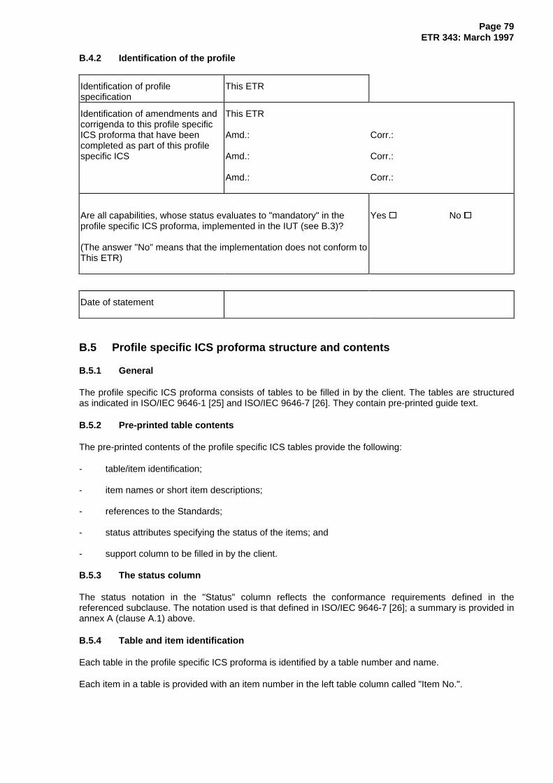
Page 79ETR 343: March 1997
B.4.2 Identification of the profile
Identification of profilespecification
This ETR
Identification of amendments andcorrigenda to this profile specificICS proforma that have beencompleted as part of this profilespecific ICS
This ETR
Amd.:
Amd.:
Amd.:
Corr.:
Corr.:
Corr.:
Are all capabilities, whose status evaluates to "mandatory" in theprofile specific ICS proforma, implemented in the IUT (see B.3)?
(The answer "No" means that the implementation does not conform toThis ETR)
Yes � No �
Date of statement
B.5 Profile specific ICS proforma structure and contents
B.5.1 General
The profile specific ICS proforma consists of tables to be filled in by the client. The tables are structuredas indicated in ISO/IEC 9646-1 [25] and ISO/IEC 9646-7 [26]. They contain pre-printed guide text.
B.5.2 Pre-printed table contents
The pre-printed contents of the profile specific ICS tables provide the following:
- table/item identification;
- item names or short item descriptions;
- references to the Standards;
- status attributes specifying the status of the items; and
- support column to be filled in by the client.
B.5.3 The status column
The status notation in the "Status" column reflects the conformance requirements defined in thereferenced subclause. The notation used is that defined in ISO/IEC 9646-7 [26]; a summary is provided inannex A (clause A.1) above.
B.5.4 Table and item identification
Each table in the profile specific ICS proforma is identified by a table number and name.
Each item in a table is provided with an item number in the left table column called "Item No.".

Page 80ETR 343: March 1997
B.6 Guidance for completion of the profile specific ICS proforma
The profile specific ICS proforma is completed by providing answers in the "Support" column to thequestions posed in the "Profile feature" column of each table. In most cases the client is only required totick the appropriate "Yes" or "No" box. In a few cases, a "not applicable" (n/a) box needs to be ticked, ornumeric values entered.
For each mandatory item that has not been implemented, the client should include a justification for notimplementing it. This should be provided as a note added at the relevant profile specific ICS page.
B.7 Profile specific ICS tables
B.7.1 Supported protocols
Table B.1: Supported protocols
Item Profile feature Status Reference Support
L1bas Does the IUT support basic access at layer 1? o.1 (note 1) 4.1.1 Yes � No �L1prim Does the IUT support primary rate interface at
layer 1?o.1 (note 1) 4.1.1 Yes � No �
L2/LAPD Does the IUT support LAPD procedures specifiedin ETS 300 402, parts 1 [10], 2 [11] and 4 [12] atlayer 2 of the D-channel?
m 4.1.1 Yes � No �
L2/7776 Does the IUT support ISO/IEC 7776 [17] protocolat layer 2 of the B-channel?
m 4.1.1 Yes � No �
L2/XID Does the IUT support XID procedures specified inISO/IEC 8885 [23] at layer 2 of the B-channel?
o 4.1.1 Yes � No �
L3/DSS1 Does the IUT support DSS1 procedures specifiedin ETS 300 403, parts 1 [13], 2 [14] and 3 [15] atlayer 3 of the D-channel?
m 4.1.1 Yes � No �
L3/X25 Does the IUT support ITU-T Rec. X.25 [4] PLPspecified in ISO/IEC 8208 [20] at layer 3 of the B-channel?
m 4.1.1 Yes � No �
L3/CONS Does the IUT support OSI CONS with mapping tothe elements of ITU-T Rec. X.25 [4] as specified inISO/IEC 8878 [22]?
o 4.1.1 Yes � No �
L4/T70 Does the IUT support the ISDN telematic transportservice (ITU-T Recs. T.70 [3] and X.224 [29]) atlayer 4?
o (note 2) 4.1.1 Yes � No �
L4/8073 Does the IUT support the COTS(ISO/IEC 8073 [19] protocol) at layer 4?
o (note 2) 4.1.1 Yes � No �
SYN Does the IUT support co-ordinated operation ofthe procedures on the B-channel with those of theD-channel?
m 4.1.2 Yes � No �
EES Does the IUT support procedures for octetalignment of the B-channel?
m 4.4.2 Yes � No �
NOTE 1: o.1 - support of one, and only one, of these options is required.NOTE 2: The "implementation" (IUT) about which this profile specific ICS proforma asks questions
corresponds to one configuration on top of ONE physical interface (i.e. one ISDN Basicaccess or one ISDN Primary rate access interface structure). If the TE supports more thanone interface or configuration of that interface, then a profile specific ICS should be createdfor each type of interface (and for each configuration of each interface) provided by the TE.
NOTE 3: ITU-T Rec. means ITU-T Recommendation.
B.7.2 Profile specific ICS proforma for the physical layer
There are no profile specific requirements for the physical layer, thus, no profile specific ICS proforma isprovided.
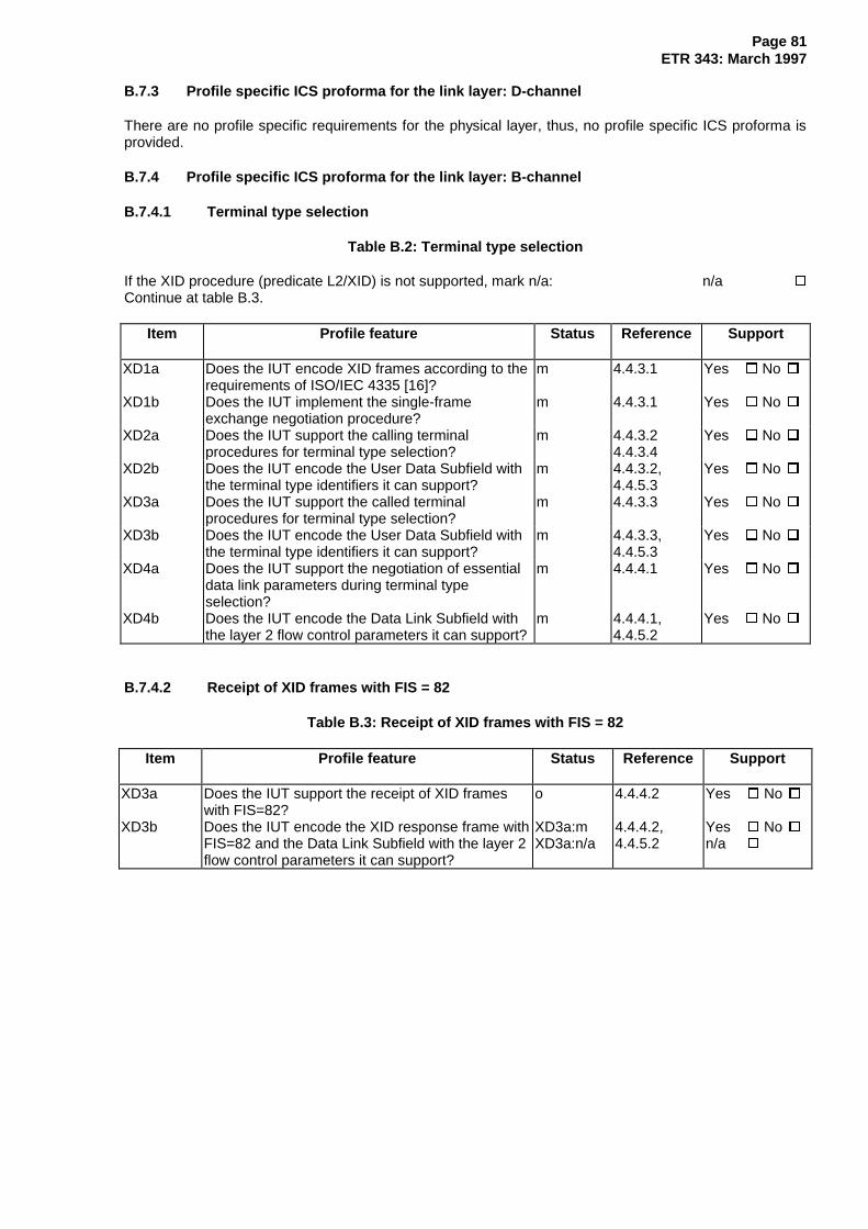
Page 81ETR 343: March 1997
B.7.3 Profile specific ICS proforma for the link layer: D-channel
There are no profile specific requirements for the physical layer, thus, no profile specific ICS proforma isprovided.
B.7.4 Profile specific ICS proforma for the link layer: B-channel
B.7.4.1 Terminal type selection
Table B.2: Terminal type selection
If the XID procedure (predicate L2/XID) is not supported, mark n/a: n/a �
Continue at table B.3.
Item Profile feature Status Reference Support
XD1a Does the IUT encode XID frames according to therequirements of ISO/IEC 4335 [16]?
m 4.4.3.1 Yes � No �
XD1b Does the IUT implement the single-frameexchange negotiation procedure?
m 4.4.3.1 Yes � No �
XD2a Does the IUT support the calling terminalprocedures for terminal type selection?
m 4.4.3.24.4.3.4
Yes � No �
XD2b Does the IUT encode the User Data Subfield withthe terminal type identifiers it can support?
m 4.4.3.2,4.4.5.3
Yes � No �
XD3a Does the IUT support the called terminalprocedures for terminal type selection?
m 4.4.3.3 Yes � No �
XD3b Does the IUT encode the User Data Subfield withthe terminal type identifiers it can support?
m 4.4.3.3,4.4.5.3
Yes � No �
XD4a Does the IUT support the negotiation of essentialdata link parameters during terminal typeselection?
m 4.4.4.1 Yes � No �
XD4b Does the IUT encode the Data Link Subfield withthe layer 2 flow control parameters it can support?
m 4.4.4.1,4.4.5.2
Yes � No �
B.7.4.2 Receipt of XID frames with FIS = 82
Table B.3: Receipt of XID frames with FIS = 82
Item Profile feature Status Reference Support
XD3a Does the IUT support the receipt of XID frameswith FIS=82?
o 4.4.4.2 Yes � No �
XD3b Does the IUT encode the XID response frame withFIS=82 and the Data Link Subfield with the layer 2flow control parameters it can support?
XD3a:mXD3a:n/a
4.4.4.2,4.4.5.2
Yes � No �n/a �
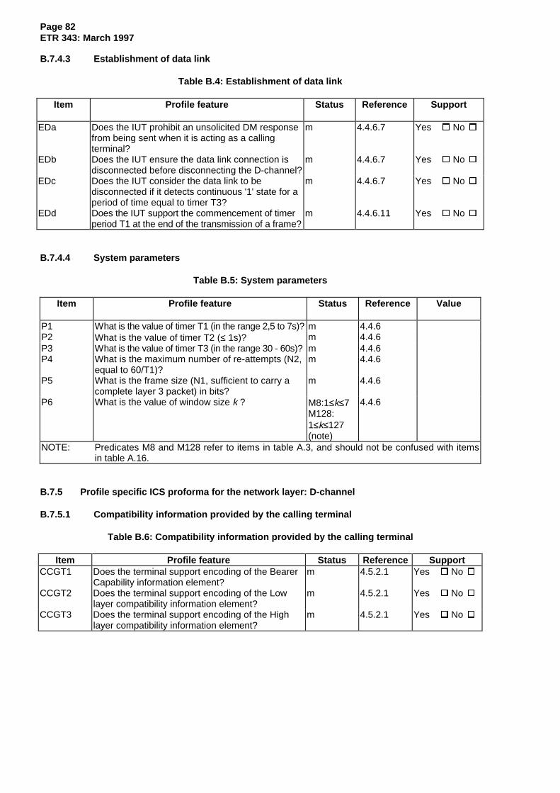
Page 82ETR 343: March 1997
B.7.4.3 Establishment of data link
Table B.4: Establishment of data link
Item Profile feature Status Reference Support
EDa Does the IUT prohibit an unsolicited DM responsefrom being sent when it is acting as a callingterminal?
m 4.4.6.7 Yes � No �
EDb Does the IUT ensure the data link connection isdisconnected before disconnecting the D-channel?
m 4.4.6.7 Yes � No �
EDc Does the IUT consider the data link to bedisconnected if it detects continuous '1' state for aperiod of time equal to timer T3?
m 4.4.6.7 Yes � No �
EDd Does the IUT support the commencement of timerperiod T1 at the end of the transmission of a frame?
m 4.4.6.11 Yes � No �
B.7.4.4 System parameters
Table B.5: System parameters
Item Profile feature Status Reference Value
P1 What is the value of timer T1 (in the range 2,5 to 7s)? m 4.4.6P2 What is the value of timer T2 (≤ 1s)? m 4.4.6P3 What is the value of timer T3 (in the range 30 - 60s)? m 4.4.6P4 What is the maximum number of re-attempts (N2,
equal to 60/T1)?m 4.4.6
P5 What is the frame size (N1, sufficient to carry acomplete layer 3 packet) in bits?
m 4.4.6
P6 What is the value of window size k ? M8:1≤k≤7M128:1≤k≤127(note)
4.4.6
NOTE: Predicates M8 and M128 refer to items in table A.3, and should not be confused with itemsin table A.16.
B.7.5 Profile specific ICS proforma for the network layer: D-channel
B.7.5.1 Compatibility information provided by the calling terminal
Table B.6: Compatibility information provided by the calling terminal
Item Profile feature Status Reference SupportCCGT1 Does the terminal support encoding of the Bearer
Capability information element?m 4.5.2.1 Yes � No �
CCGT2 Does the terminal support encoding of the Lowlayer compatibility information element?
m 4.5.2.1 Yes � No �
CCGT3 Does the terminal support encoding of the Highlayer compatibility information element?
m 4.5.2.1 Yes � No �

Page 83ETR 343: March 1997
B.7.5.2 Compatibility checking by the called terminal
Table B.7: Compatibility checking by the called terminal
Item Profile feature Status Reference SupportCCDT1 Does the called terminal support compatibility
checking of the addressing information?m 4.5.2.2 a) Yes � No �
CCDT2 Does the called terminal support network to usercompatibility checking?
m 4.5.2.2 b) Yes � No �
CCDT3 Does the called terminal support user to usercompatibility checking based on the content of theLow layer compatibility (LLC) information element?
m 4.5.2.2 c) 1) Yes � No �
CCDT4 Does the called terminal support user to usercompatibility checking based on the content of theHigh layer compatibility (HLC) informationelement?
m 4.5.2.2 c) 2) Yes � No �
CCDT5 Does the called terminal support outbandnegotiation?
o 4.5.2.3 Yes � No �
CCDT6 Does the called terminal support the callacceptance conditions?
m 4.5.2.4 Yes � No �
B.7.5.3 Interworking with other networks
Table B.8: Interworking with other networks
Item Profile feature Status Reference SupportIWa Does the IUT support interworking with non-ISDNs
for outgoing calls?n/a 4.5.3.1.1 n/a
IWb Does the IUT support interworking with non-ISDNsfor incoming calls?
m 4.5.3.1.2 Yes � No �
IWc Does the IUT support interworking with privatetelecommunication networks (note)?
m 4.5.3.2 Yes � No �
IWd Does the IUT support interworking with a networkhaving restricted bearer capability?
o 4.5.3.3 Yes � No �
NOTE: This question relates specifically to interworking with private telecommunication networks thatuse the inter-exchange signalling protocol specified in ETS 300 172 [7]. It does not coverinterworking with private networks using other signalling protocols.
B.7.5.4 Use of ISDN supplementary services
Table B.9: Use of ISDN supplementary services
Item Profile feature Status Reference SupportSSa Does the IUT support the use of ISDN
supplementary services in conjunction withtelematic applications?
n/a 4.5.4 n/a

Page 84ETR 343: March 1997
B.7.6 Profile specific ICS proforma for the network layer: B-channel
Table B.10: Logical channels
Item Profile feature Reference Status SupportLCa Does the IUT support a single two-way logical
channel?4.6.2 m Yes � No �
LCb Does the IUT support 2 or more two-way logicalchannels?
4.6.2 o Yes � No �
LCc Does the IUT set the parameter LTC to the valueof 1?
4.6.2 m Yes � No �
LCd Does the IUT set the parameter HTC to the valueof 1?
4.6.2 LCb:n/aLCb:m
n/a �
Yes � No �SPIa Does the IUT support Subsequent Protocol
Identifiers (SPI) as the 1st octet of the Call userdata field of CALL REQUEST/INCOMING CALLpackets?
4.6.3.3 m Yes � No �
FCN Does the IUT support flow control parameternegotiation for every virtual call?
4.6.4.1 m Yes � No �
PSa Is the IUT capable of handling packet sizes of 256,512, 1 024, and 2 048 octets?
4.6.4.2 o Yes � No �
PSb During flow control parameter negotiation, doesthe IUT propose a value for packet size of 512octets?
4.6.4.2 o.2 Yes � No �
PSc During flow control parameter negotiation, doesthe IUT propose a value for packet size of 1 024octets?
4.6.4.2 o.2 Yes � No �
WS During flow control parameter negotiation, doesthe IUT propose a value of 80 for window size?
4.6.4.3 o Yes � No �
PDUc Does the IUT transmit PDUs in a complete packetsequence?
4.6.6 m Yes � No �
Aq Does the IUT support the use of the Qualifier bit(Q-bit)?
4.6.7 o Yes � No �
ERRa On receipt of a REGISTRATION REQUESTpacket invoking an unsupported optional facility,does the IUT respond with a REGISTRATIONCONFIRMATION packet?
4.6.11 o Yes � No �
ERRb Does the IUT treat the receipt of a CALLREQUEST/INCOMING CALL packet invoking anunsupported optional facility, as an error?
4.6.11 m Yes � No �
NOTE: o.2 - Only one of the options may be supported.

Page 85ETR 343: March 1997
B.7.7 Profile specific ICS proforma for the CONS
If the layer 3 CONS (predicate L3/CONS) is not supported, mark n/a: n/a �
Continue at table B.13.
Table B.11: Additional D-channel requirements for the CONS
Item Profile feature Reference Status SupportDadd1 Does the IUT support the additional D-channel
protocol requirements specified inISO/IEC 9574 [24], modified by this ETR?
4.5, 4.7.2(note 1)
m Yes � No �
Dadd2 When operating as a CONS compliant terminal,does the IUT support encoding of the LLCinformation element as "ISO/IEC 8878 [22] use ofISO/IEC 8208 [20] and ITU-T Rec. X.25 [4] toprovide the OSI CONS"?
4.7.2.1 m Yes � No �
Dadd3 Does the IUT support use of the Subaddressingsupplementary service to convey NSAP addressesduring call establishment?
4.7.2.2 c1:mc1:n/a(note 2)
Yes � No �n/a �
Dadd4 Does the IUT support use of the User-to-Usersignalling supplementary service for conveyingnetwork service user data?
4.7.2.3 x Yes � No �
Dadd5 Does the IUT support mapping of cause values tothe reason parameter of the CONS indicationprimitive?
4.7.2.4, table10
m Yes � No �
NOTE 1: See also subclause 6.4 in ISO/IEC 9574 [24].NOTE 2: c1 - Application needs to convey NSAP addresses during the establishment of the B-channel
connection.NOTE 3: ITU-T Rec. means ITU-T Recommendation.
Table B.12: Additional B-channel requirements for the CONS
Item Profile feature Reference Status SupportBadd1 Does the IUT support the additional B-channel
protocol requirements specified inISO/IEC 9574 [24], modified by this ETR?
4.5, 4.7.2(note)
m Yes � No �
Badd2 Does the IUT support additional fields in CALLREQUEST packets, corresponding to thoseoptional facilities of ISO/IEC 8208 [20] required toprovide the CONS?
4.7.3, 4.7.3.2 m Yes � No �
Badd3 Does the IUT support encoding of called, callingand responding addresses as specified inISO/IEC 8878 [22] for conveying the full NSAPaddress?
4.7.3.1 m Yes � No �
Badd4 Does the IUT support interworking with callingterminals not supporting CONS?
4.7.3.3 m Yes � No �
Badd5 Does the IUT support use of a value of 64 kbit/sfor the Throughput QOS parameter?
4.7.3.4 m Yes � No �
Badd6 Does the IUT support use of the value"unspecified" for the Transit delay QOSparameter?
4.7.3.5 m Yes � No �
NOTE: See also subclause 6.4 in ISO/IEC 9574 [24].

Page 86ETR 343: March 1997
B.7.8 Profile specific ICS proforma for the transport layer
B.7.8.1 Profile specific ICS proforma for the ISDN telematic transport service
This profile specific ICS proforma for the ISDN telematic transport service covers the specific usage ofITU-T Recommendation T.70 [3] according to the requirements in subclause 4.8.2 of this ETR.
If the ISDN telematic transport service (predicate L4/T70) is not supported, mark n/a: n/a �
Continue at table B.19.
Table B.13: Major capabilities
Item Profile feature Reference inITU-T Rec.
T.70 [3]
Reference inThis ETR
Status Support
1 Does the IUT support transportconnection establishment andtermination; see B.14/1, B.14/2 andB.14/3?
5.1.4.1 a) 4.8.2 m Yes � No �
2 Does the IUT support transportconnection identification; see B.14/1,B.14/2 and B.14/3?
5.1.4.1 a) 4.8.2 m Yes � No �
3 Does the IUT support data transfer;see B.14/4?
5.3 4.8.2 m Yes � No �
4 Does the IUT support datadelimitation; see B.14/4?
5.1.4.1 b) 4.8.2 m Yes � No �
5 Does the IUT support segmentationand reassembling; see B.14/4?
5.1.4.1 b) 4.8.2 m (note)
6 Does the IUT supportdetection/indication of proceduralerrors; see B.14/5 and B.17?
5.1.4.1 c) 4.8.2 m Yes � No �
7 Does the IUT support recovery fromnetwork reset?
A.1.2.3 4.8.2 m Yes � No �
8 Does the IUT support recovery fromnetwork disconnection?
A.1.2.4 4.8.2 m Yes � No �
9 Does the IUT support extendedaddressing; see B.14/1, B.14/2 andB.16?
5.1.4.1 a),5.2.6
4.8.2 o Yes � No �
10 Does the IUT support protocolidentification by annex B ofITU-T Recommendation X.224 [29]?
4.8.2.4 m Yes � No �
NOTE: State the TSDU maximum size for reassembling.
Table B.14: Transport data protocol units
Item Profile feature Reference inITU-T Rec.
T.70 [3]
Reference inThis ETR
Status Support
1 Does the IUT support TCR? 5.2.2 4.8.2.2, 4.8.2.3 m Yes � No �2 Does the IUT support TCA? 5.2.3 4.8.2 m Yes � No �3 Does the IUT support TCC? 5.2.4 4.8.2.2, 4.8.2.3 o Yes � No �4 Does the IUT support TDT? 5.3 4.8.2 m Yes � No �5 Does the IUT support TBR? 5.4 4.8.2 m Yes � No �

Page 87ETR 343: March 1997
Table B.15: Transport data block size negotiation
Item Profile feature Reference inITU-T Rec.
T.70 [3]
Reference inThis ETR
Status Support
1 Does the IUT support receipt ofrequest in TCR for use of optionalTDT block length?
5.3.2.2,5.5.5.3
4.8.2 Yes � No �
2 Does the IUT support request in TCRfor use of an optional, not supportedTDT block length is not TBRresponded?
5.2.3.2 4.8.2 Yes � No �
3 Does the IUT support TDT length of128 octets (Standard length)?
5.3.2 4.8.2 m Yes � No �
4 Does the IUT support TDT length of256 octets?
5.3.2 4.8.2 o Yes � No �
5 Does the IUT support TDT length of512 octets?
5.3.2 4.8.2 o Yes � No �
6 Does the IUT support TDT length of1 024 octets?
5.3.2 4.8.2 o Yes � No �
7 Does the IUT support TDT length of2 048 octets?
5.3.2 4.8.2 o Yes � No �
8 Does the IUT support sendingrequest in TCR for use of optionalTDU block length?
5.5.4.3 4.8.2 o Yes � No �
9 Does the IUT support sendingrequest in TCA for a shorter allowableTDT block?
5.2.3.2 4.8.2 o Yes � No �
10 Does the IUT support accepting useof optional TDT size by returning sizevalue in TCA response?
5.2.3.2 4.8.2 o Yes � No �
11 Does the IUT support rejecting use ofoptional TDT size by TCA responsewithout TDT block size parameter?
5.2.3.2 4.8.2 o Yes � No �
Table B.16: Extended addressing
Item Profile feature Reference inITU-T Rec.
T.70 [3]
Reference inThis ETR
Status Support
1 Does the IUT support TCA responseon receipt of TCR with/withoutextended addressing?
5.2.6 4.8.2 c2 Yes � No �
2 Does the IUT support reaction onreceipt of TCR with/without extendedaddressing?
5.2.6 4.8.2 c2 Yes � No �
3 Does the IUT support routing in amulti-terminal configuration?
5.2.6 4.8.2 o Yes � No �
NOTE: c2 - Mandatory if extended addressing is supported.

Page 88ETR 343: March 1997
Table B.17: Procedures and reactions on protocol errors
Item Profile feature Reference inITU-T Rec.
T.70 [3]
Reference inThis ETR
Status Support
1 Does the IUT support when calling:Notifying in TBR if TCR is received?
5.2.5 4.8.2 m Yes � No �
2 Does the IUT support neglect ofincorrect extended addressing?
5.2.6.3 4.8.2 m Yes � No �
3 Does the IUT support no reject ofTDT/TSDU with end mark 0 and sizeless than maximum?
5.3.2.2 4.8.2 m Yes � No �
4 Does the IUT support acceptingTDT/TSDU with end mark 1 and nouser information?
5.3.3.1 4.8.2 m Yes � No �
5 Does the IUT support sending TBR toreport receipt of invalid/notimplemented block (except in states0.3/1.1 (calling) and 0.2 (called))?
5.4 4.8.2 m Yes � No �
6 Does the IUT support ignoringinvalid/not implementedparameters/values in received TCRduring transport connectionestablishment?
5.4 4.8.2 m Yes � No �
7 Does the IUT support valid or invalidTBR is not answered by sendingTBR?
5.4 4.8.2 m Yes � No �
8 Does the IUT support indication ofclearing cause in TCC?
5.5.6.1 4.8.2 m Yes � No �
9 Does the IUT support provision ofadditional clearing information inTCC?
5.5.6.2 4.8.2 o Yes � No �
10 Does the IUT support indication ofreject cause in TBR?
5.5.7.1 4.8.2 m Yes � No �
11 Does the IUT support return ofrejected block in TBR?
5.5.7.1 4.8.2 m Yes � No �
12 Does the IUT support indication ofonly the first procedural/parametererror in TBR?
5.5.7.2 4.8.2 m Yes � No �
13 Does the IUT support networkdisconnection request if timeoutoccurs in states 0.3/1.1 (calling) or0.2/0.3 (called)?
Fig:A.14 4.8.2 m Yes � No �
14 Does the IUT support networkdisconnect request if invalid/notimplemented block is received instates 0.2 (called) or 1.1 (calling)?
Fig:A.14 4.8.2 m Yes � No �
15 Does the IUT support discard of anyreceived block in state 0.3?
Fig:A.14/A.15 4.8.2 m Yes � No �
16 Does the IUT support use ofT_EXCEPTION indication?
A.1.1.3 4.8.2 o Yes � No �
17 Does the IUT support request ofnetwork disconnection if TBR isreceived in state 2.1 andT_EXCEPTION indication is notsupported?
Fig.A.15 4.8.2 c3 Yes � No �
18 Does the IUT support on receipt ofTCC: Re-sending TCR(s)?
5.2.4.1 4.8.2 o (1)
NOTE: c3 - Mandatory if item T5/16 is not supported.

Page 89ETR 343: March 1997
Table B.18: Timers
Item Profile feature Referencein T.70
Reference inThis ETR
Status Support
1 Does the IUT support timer state 0.2(called side) with value approx. 60 s?
table B.4,item E11 andtable B.5
4.8.2.1 m Yes � No �
2 Does the IUT support timer state 0.3(calling/called side) with value approx.60 s?
table B.4,item E11 andtable B.5
4.8.2.1 m Yes � No �
3 Does the IUT support timer state 1.1(calling side) with value approx. 60 s?
table B.4,item E11 andtable B.5
4.8.2.1 m Yes � No �
B.7.8.2 Profile specific ICS proforma for the COTS
If the layer 4 COTS (predicate L4/8073) is not supported, mark n/a: n/a �
The tables in this subclause are then not applicable.
Table B.19: Layer 4 protocol - Base standard/Recommendation conformance
Item Profile feature Reference Status Support
PID1 Does the IUT support protocol identification byannex B of ISO/IEC 8073 [19]?
4.8.3.9 o.2 Yes � No �
PID2 Does the IUT support protocol identification byannex B of ITU-T Recommendation X.224 [29]?
4.8.3.9 o.2 Yes � No �
NOTE: o.2 - Support of one, and only one, of these options is required.
Table B.20: Timers
Item Profile feature Reference Status SupportOT1 (class 0) Is the value of timer TS1 = 60 s approx. 4.8.3.7 m Yes � No �OT3 (class 2) Is the value of timer TS1 = 60 s approx. 4.8.3.7 m Yes � No �OT5 (class 0) Is the value of timer TS2 = 60 s approx. 4.8.3.7 m Yes � No �OT7 (class 2) Is the value of timer TS2 = 60 s approx. 4.8.3.7 m Yes � No �
Table B.21: Error handling
Item Profile feature Reference Status SupportPE0 Does the IUT support treatment of protocol errors;
ER-TPDU sent (Class 0)?4.8.3.10 m Yes � No �
PE2 Does the IUT support treatment of protocol errors;ER-TPDU sent (Class 2)?
4.8.3.10 m Yes � No �

Page 90ETR 343: March 1997
Annex C: Applicability of this ETR
This annex contains a description of the scenario to which the requirements of this ETR apply. This isillustrated in figure C.1.
Figure C.1: Applicability of this ETR
The "reference end system" or "calling TE" is a system (or TE) to which the requirements of this ETRapply. The "remote end system" or "called TE" is another system (or TE) to which the reference endsystem attempts to establish communication. A reference end system may also be a system or TE towhich communication is established from a remote end system. In this respect a reference end systemperforms the functions of a called TE. The reference end system may or may not be operating in an OSIenvironment.
The reference end system communicates with the remote end system through an Integrated ServicesDigital Network (ISDN). The reference end system is directly attached to the ISDN at an S reference point,at a T reference point, or at a coincident S and T reference point. The remote end system may or may notconform to the requirements of this recommendation. It may be using a different access method on anISDN or another subnetwork technology.
Communication between the reference end system and remote end system is via a single or multipleISDN(s), or via combination of ISDN(s) and single or multiple intermediate systems.
In this scenario, the ISDN provides a circuit-mode 64 kbit/s unrestricted bearer service between thereference end system and the compatible end system or an intermediate system. The D-channel is usedto carry signalling relating to the establishment and control of the B-channel connections. The B-channelconnections carry the user information. The end systems communicate with one another via one or morevirtual calls (ITU-T Recommendation X.25 [4] DTE to DTE operation) on the B-channel.
The requirements in clause 4 of this recommendation are described in a way that assumes that theremote end system conforms to the recommendations in this ETR and that the complete facilities of theD-channel signalling system are available. In a practical situation, this may not always be the case;appropriate requirements are included in the recommendation to cater for this.
Memorandum M-IT-02 on the taxonomy of profiles for systems operating in an OSI environment, containsfurther information on the relationship between reference end systems and remote end systems. Inparticular, it provides information on how the profile described in this ETR fits into the overall framework ofprofiles for interworking in an OSI environment. The profile described in this ETR matches profilesT/C4211 and T/D4211 described in ITSTC Memorandum M-IT-02 (see annex D). These profiles specify acombination of standards (the same combination as specified in subclause 4.1 of this ETR) that provide aConnection-mode Transport Service (classes 0 and 2 for T/C4211 and class 0 for T/D4211). However thisETR goes further than this.
** Other compatible network equipment
- none - another ISDN - OSI relays - other equipment
Reference
end system
ISDN
(public or private)
**Remote
end system
This ETR

Page 91ETR 343: March 1997
Annex D: Bibliography
The following documents provide useful additional information:
- ITU-T Recommendation X.29 (1988): "Procedures for the exchange of controlinformation and user data between a Packet Assembly/Disassembly facility(PAD) and a packet mode DTE or another PAD".
- ITU-T Recommendation X.75 (1984): "Packet-switched signalling systembetween public networks providing data transmission services".
- ENV 41112 (1991): "Information Systems Interconnection - ISDN - Provision ofthe OSI connection-mode transport service over the OSI connection-modenetwork service by using an ISDN circuit-mode 64 kbit/s unrestricted bearerservice - Demand case".
- ETR 018 (1994): "Integrated Services Digital Network (ISDN); Application of theBearer Capability (BC) -, High Layer Compatibility (HLC) - and Low LayerCompatibility (LLC) - information elements by terminals supporting ISDNservices".
- ETR 026 (1992): "Network Aspects (NA); Terminal selection principles forpriority I and II services of MoU-ISDN, applicable in multi-terminal environmentsat customer premises".
- ETR 076: "Integrated Services Digital Network (ISDN); Standards guide" (Inparticular section A.5).
- ETS 300 102-1 (1990): "Integrated Services Digital Network (ISDN); User-network interface layer 3, Specifications for basic call control".
- ETS 300 102-2 (1990): "Integrated Services Digital Network (ISDN); User-network interface layer 3, Specifications for basic call control, SpecificationDescription Language (SDL) diagrams".
- ISO 7498 (1984): "Information processing systems - Open SystemsInterconnection - Basic Reference Model".
- ISO/IEC TR 9577 (1993): "Information technology - Telecommunications andinformation exchange between systems - Protocol identification in the networklayer".
- ISO/IEC TR 10000-1 (1992): "Information technology - Framework andtaxonomy of International Standardized Profiles - Part 1: Framework".
- ISO/IEC TR 10178 (1994): "Information technology - Telecommunications andinformation exchange between systems - The structure and coding of LogicalLink Control addresses in Local Area Networks".
- ITU-T Recommendation T.4 (1994): "Terminal equipments and protocols fortelematic services - Standardization of Group 3 facsimile apparatus fordocument transmission".
- ITU-T Recommendation T.30 (1994): "Terminal equipments and protocols fortelematic services - Procedures for document facsimile transmission in thegeneral switched telephone network".
- CEN / CENELEC / ETSI Information Technology Steering Committee(ITSTC) Memorandum M-IT-02 (1991): "Taxonomy of profiles and directory offunctional standards for interworking in an OSI environment to be adopted byCEN/CENELEC/ETSI ITSTC" Issue 5.

Page 92ETR 343: March 1997
- ITU-T Recommendation X.31: "Support of packet mode terminal equipment byan ISDN".
- ETS 300 402, Parts 1 to 7 (1995): "Integrated Services Digital Network (ISDN);Digital Subscriber Signalling System No. one (DSS1) protocol; Data link layer".
- ETS 300 403, Parts 1 to 7 (1995): "Integrated Services Digital Network (ISDN);Digital Subscriber Signalling System No. one (DSS1) protocol; Signallingnetwork layer for circuit-mode basic call control".
- ETS 300 406 (1995): "Methods for Testing and Specification (MTS); Protocoland profile conformance testing specifications; Standardization methodology".
- ETS 300 079 (1991): "Integrated Services Digital Network (ISDN); Syntax-basedvideotex End-to-end protocols, circuit mode DTE-DTE".
- ETS 300 087 (1994): "Integrated Services Digital Network (ISDN); Facsimilegroup 4 class 1 on the ISDN Functional specification of the equipment".
- ETS 300 112 (1994): "Integrated Services Digital Network (ISDN); Facsimilegroup 4 class 1 equipment on the ISDN End-to-end protocols".
- ETS 300 218 (1993): "Integrated Services Digital Network (ISDN); Syntax-basedvideotex lower layer protocols for ISDN packet mode (ITU-T RecommendationX.31 Case A and Case B)".
- ETS 300 262 (1993): "Integrated Services Digital Network (ISDN); Syntax-basedVideotex teleservice Service description".
- ETS 300 383 (1995): "Integrated Services Digital Network (ISDN); File transferover the ISDN EUROFILE transfer profile".
- ETS 300 388 (1995): "Integrated Services Digital Network (ISDN); File TransferAccess & Management (FTAM) over ISDN based on simple file transfer profile".
- ETS 300 409 (1995): "Integrated Services Digital Network (ISDN); Eurofiletransfer teleservice; Service description".
- ETS 300 410 (1995): "Integrated Services Digital Network (ISDN); File Transfer& Access Management (FTAM) teleservice; Service description".
- ETR 173 (1995): "Terminal Equipment (TE):Functional model for multimediaapplications".
- ETR 197 (1995): "Network Aspects (NA); Baseline document on multimediaservices".
- ETR 228 (1995): "Terminal Equipment (TE); Broadband Multimedia InformationRetrieval Services".
- ISO/IEC 1745 (1975): "Information processing - Basic mode control proceduresfor data communication systems".
- ISO/IEC 8802/2 (1994): "Information technology - Telecommunications andinformation exchange between systems - Local and metropolitan areanetworks - Specific requirements - Part 2: Logical link control".
- ISO/IEC 8473 (1994): "Information technology - Protocol for providing theconnectionless-mode network service: Protocol specification".
- CCITT Recommendation T.71 (1998): "Link access protocol balanced (LAPB)extended for half-duplex physical level facility".

Page 93ETR 343: March 1997
- ITU-T Recommendation Q.921 (1993): "ISDN user-network interface – Data linklayer specification".
- ITU-T Recommendation Q.931 (1993): "ISDN user-network interface layer 3specification for basic call control".

Page 94ETR 343: March 1997
History
Document history
March 1997 First Edition
ISBN 2-7437-1256-2Dépôt légal : Mars 1997