ETR 320 - Intelligent Network (IN); Security requirements ... · ETR may be used to publish...
38
ETSI ETR 320 TECHNICAL November 1996 REPORT Source: ETSI TC-NA Reference: DTR/NA-006004 ICS: 33.020 Key words: IN, security Intelligent Network (IN); Security requirements for global IN systems ETSI European Telecommunications Standards Institute ETSI Secretariat Postal address: F-06921 Sophia Antipolis CEDEX - FRANCE Office address: 650 Route des Lucioles - Sophia Antipolis - Valbonne - FRANCE X.400: c=fr, a=atlas, p=etsi, s=secretariat - Internet: [email protected] Tel.: +33 4 92 94 42 00 - Fax: +33 4 93 65 47 16 Copyright Notification: No part may be reproduced except as authorized by written permission. The copyright and the foregoing restriction extend to reproduction in all media. © European Telecommunications Standards Institute 1996. All rights reserved.
Transcript of ETR 320 - Intelligent Network (IN); Security requirements ... · ETR may be used to publish...

ETSI ETR 320
TECHNICAL November 1996
REPORT
Source: ETSI TC-NA Reference: DTR/NA-006004
ICS: 33.020
Key words: IN, security
Intelligent Network (IN);Security requirements for global IN systems
ETSI
European Telecommunications Standards Institute
ETSI Secretariat
Postal address: F-06921 Sophia Antipolis CEDEX - FRANCEOffice address: 650 Route des Lucioles - Sophia Antipolis - Valbonne - FRANCEX.400: c=fr, a=atlas, p=etsi, s=secretariat - Internet: [email protected]
Tel.: +33 4 92 94 42 00 - Fax: +33 4 93 65 47 16
Copyright Notification: No part may be reproduced except as authorized by written permission. The copyright and theforegoing restriction extend to reproduction in all media.
© European Telecommunications Standards Institute 1996. All rights reserved.

Page 2ETR 320: November 1996
Whilst every care has been taken in the preparation and publication of this document, errors in content,typographical or otherwise, may occur. If you have comments concerning its accuracy, please write to"ETSI Editing and Committee Support Dept." at the address shown on the title page.

Page 3ETR 320: November 1996
Contents
Foreword .......................................................................................................................................................5
1 Scope ..................................................................................................................................................7
2 References..........................................................................................................................................8
3 Abbreviations and definitions ..............................................................................................................93.1 Abbreviations .......................................................................................................................93.2 Definitions ..........................................................................................................................10
4 Introduction........................................................................................................................................10
5 The IN system ...................................................................................................................................115.1 The domain structure and the need for interworking .........................................................115.2 Actors and roles.................................................................................................................125.3 IN management .................................................................................................................135.4 The modes of communications between IN entities ..........................................................14
6 Threat analysis ..................................................................................................................................146.1 Introduction ........................................................................................................................146.2 Threat analysis of IN relationships inside one domain ......................................................16
6.2.1 Generic threats to IN relationships ................................................................166.2.2 Threat analysis of the SCF-SRF relationship ................................................186.2.3 Sensitivity of the Core INAP Information Flows.............................................18
6.3 Threats to IN management ................................................................................................186.4 Interworking threats ...........................................................................................................196.5 Conclusions .......................................................................................................................19
7 Security requirements .......................................................................................................................207.1 Introduction ........................................................................................................................207.2 Baseline security requirements..........................................................................................207.3 Security and the mode of interaction between IN entities..................................................227.4 Security requirements for co-operating IN entities inside one domain ..............................227.5 Security requirements for IN management ........................................................................237.6 Security requirements for the interworking function...........................................................247.7 Fraud management ...........................................................................................................24
Annex A: The process of assessing and specifying security in IN .........................................................26
A.1 Strategic security requirements.........................................................................................................26
A.2 Regulations .......................................................................................................................................26
A.3 System description ............................................................................................................................26
A.4 Threat analysis ..................................................................................................................................27
A.5 Security requirements .......................................................................................................................28
A.6 Selection of security mechanisms and cost/benefit analysis ............................................................28
A.7 Risk analysis .....................................................................................................................................28
A.8 The security architecture and security management ........................................................................29

Page 4ETR 320: November 1996
Annex B: Detailed description of the IN system..................................................................................... 30
B.1 General functional description .......................................................................................................... 30B.1.1 End user access................................................................................................................ 30B.1.2 Service invocation and control .......................................................................................... 31B.1.3 End user interaction with service control........................................................................... 31B.1.4 IN management................................................................................................................. 31B.1.5 Inter working between service processing functional entities ........................................... 31
B.2 Functional description of each component ....................................................................................... 31B.2.1 CCAF................................................................................................................................. 31B.2.2 CCF................................................................................................................................... 32B.2.3 SSF ................................................................................................................................... 32B.2.4 SCF ................................................................................................................................... 32B.2.5 SDF ................................................................................................................................... 33B.2.6 SRF ................................................................................................................................... 33B.2.7 SCUA ................................................................................................................................ 33B.2.8 SCAF................................................................................................................................. 34
Annex C: Threat analysis of the core INAP information flows................................................................ 35
Annex D (informative): Bibliography ....................................................................................................... 37
History ......................................................................................................................................................... 38

Page 5ETR 320: November 1996
Foreword
This ETSI Technical Report (ETR) has been produced by the Network Aspects (NA) Technical Committeeof the European Telecommunications Standards Institute (ETSI).
ETRs are informative documents resulting from ETSI studies which are not appropriate for EuropeanTelecommunication Standard (ETS) or Interim European Telecommunication Standard (I-ETS) status. AnETR may be used to publish material which is either of an informative nature, relating to the use or theapplication of ETSs or I-ETSs, or which is immature and not yet suitable for formal adoption as an ETS oran I-ETS.
This ETR describes the result of security studies undertaken by ETSI Network Aspects TechnicalCommittee (Intelligent Networks) in 1993.

Page 6ETR 320: November 1996
Blank page

Page 7ETR 320: November 1996
1 Scope
This ETSI Technical Report (ETR) provides the identification of the security requirements of an IntelligentNetwork (IN) structured network. These requirements are designed to allow a network operator or serviceprovider to meet the following objectives:
− to operate a network or service efficiently and reliably;
− maintain customer satisfaction and good will;
− attract new business.
It is necessary to consider IN security along with reliability, service processing, management and servicecreation requirements to ensure comprehensive network protection.
In this ETR, IN security is considered under two categories:
1) protection of the network by ensuring that service creation, management, data and processing areproperly implemented;
2) security offered in or provided by IN services.
Category 1: Security of IN protocol operations
It is concerned with the security of IN-entities: secure communication between entities and secure storageof data within those entities (or under their jurisdictions). This category concentrates on the Physical andDistributed Functional Planes. Parties involved herein are: Service Providers and Network Operators.End-Users and Subscribers are not considered at this level, but user information stored in or transportedbetween IN entities are.
Also the interface between the management facilities and the manager and between the service creationenvironment and the service creator are important at this level. Inter-domain and intra-domain securityaspects also belong to this category.
Mobility requirements have not fully been investigated in this ETR. When the mobility functionality isgetting more mature and stable, it may require additional security requirements. This is for further study.
Category 2: Security offered in or provided by IN
This category concentrates on the Service and Global Functional Planes. The objective here is to defineand specify security features and building blocks for the use in IN-services, such as an AuthenticationService Independent building Block (SIB) and a User interaction SIB, which can be used for userauthentication in Universal Personal Telecommunication (UPT), Universal Mobile TelecommunicationsSystem (UMTS), etc. Parties involved are: Users and Service Providers. These security SIBs and featureswill make use of the secured IN-entities of category 1.
The main objective of this ETR is to specify a well-balanced set of security requirements for protecting theinteractions between co-operating IN entities and the path between the user and the service provider.Category 2 is for further study.
Method
A step-wise approach is used to assess and specify security, and in the early phase an attempt is made tolimit the security considerations to the generic part of the IN system, i.e. category 1. A description of thismethod is given in annex A.
In this ETR, IN, security policy, threats and requirements are described. The next document deals withmechanisms, protocols and algorithms.
The most fundamental property of global communications is its inherent domain structure. This ETRdiscusses this matter in some detail. This will complement a thorough description of the IN system drawnfrom various sources, to identify logical components of the system and their interfaces, and the

Page 8ETR 320: November 1996
information (messages) flowing between those components. This will provide the basis for the threatanalysis in order to arrive at the security requirements.
IN system description
Threat analysis
Security requirements
Security mechanismsSecurity protocols
Security algorithmsSecurity architecture
Figure 1: The various steps in specifying IN security
Organization of this ETR
The remainder of this ETR is organized according to the step-wise approach used to assess and specifysecurity. Clause 5 describes the global IN system and identifies the various actors and the roles they mayplay, identify addressable system components and their functions and interfaces, and the informationflowing between those components. All this information is necessary to perform a thorough threat analysiswhich is described in clause 6. Finally the threats are converted into security requirements in clause 7,after an assessment of the importance of the various threats that have been identified. There are threeannexes to this ETR. Annex A outlines the step-wise method used to assess and specify securityrequirements. Annex B provides a detailed description of the IN system, and annex C provides a coarsethreat analysis of the information flows between the IN functional entities.
2 References
This ETR incorporates by dated or undated reference, provisions from other publications. Thesereferences are cited at the appropriate places in the text and the publications are listed below. For datedreferences subsequent amendments to, or revisions of, any of these publications apply to this ETR onlywhen incorporated in it by amendment or revision. For undated references the latest edition of thepublication referred to applies.
[1] ETS 300 374-1: "Intelligent Network (IN); Intelligent Network Capability Set 1(CS1) Core Intelligent Network Application Protocol (INAP) Part 1: Protocolspecification".
[2] ETR 318: "Intelligent Network (IN); IN Capability Set 1 (CS1) Distributedfunctional plane".
[3] ETR 323: "Intelligent Network (IN); Service life cycle reference model forservices supported by an IN".
[4] ETR 319: "Intelligent Network (IN); IN intra domain management requirementsfor Capability Set 2 (CS-2)".
[5] ETR 322: "Intelligent Network (IN); Vocabulary of terms and abbreviations".

Page 9ETR 320: November 1996
[6] ETR 232: "Network Aspects (NA); Security Techniques Advisory Group (STAG);Glossary of security terminology".
[7] ETR 083: "Universal Personal Telecommunication (UPT); General UPT securityarchitecture".
[8] ECMA TR/46 (1988): "Security in Open Systems - A Security Framework".
[9] ECMA 138 (1989): "Security in Open Systems - Data Elements and ServiceDefinitions".
[10] ISO 7498-2: "Information processing systems - Open Systems Interconnection -Basic Reference Model - Part 2: Security Architecture".
[11] ISO 10181-1 to ISO 10181-7: "Information technology - Open SystemsInterconnection - Security Frameworks for Open Systems".
[12] CCITT Recommendation M.3010 (1991): "Principles for a telecommunicationsmanagement network".
[13] ITU-T Recommendation Q.1214: "Distributed functional plane for intelligentnetwork CS-1".
[14] CCITT Recommendation X.509 / ISO 9594-8: "Information technology - OpenSystems Interconnection - The directory: authentication framework".
3 Abbreviations and definitions
3.1 Abbreviations
For the purposes of this ETR, the following abbreviations apply:
BCSM Basic Call State ModelB-ISDN Broadband Integrated Services Digital NetworkBRI Basic Rate InterfaceCCA Call Control AgentCCAF Call Control Agent FunctionCCF Call Control FunctionCCSN Common Channel Signalling NetworkCS Capability SetDFP Distributed Functional PlaneFE Functional EntityIN Intelligent NetworkINAP Intelligent Network Application ProtocolISDN Integrated Services Digital NetworkITSEC Information Technology Security Evaluation CriteriaIWF Interworking FunctionNE Network ElementNO Network OperatorONP Open Network ProvisionOSF Operations System FunctionPLMN Public Land Mobile NetworkPNO Public Network OperatorPP Physical PlanePRI Primary Rate InterfaceQoS Quality of ServiceSCAF Service Control Agent FunctionSCEAF Service Creation Environment Access FunctionSCEF Service Creation FunctionalitySCF Service Control FunctionSCUA Service Control User AgentSCUAF Service Control User Agent Function

Page 10ETR 320: November 1996
SDF Service Data FunctionSIB Service Independent building BlockSP Service ProviderSRF Specialized Resource FunctionSS7 Signalling System No.7SSF Service Switching FunctionSTP Signalling Transfer PointTMN Telecommunication Management NetworkTTP Trusted Third PartyUMTS Universal Mobile Telecommunications SystemUPT Universal Personal TelecommunicationWSF Workstation Function
3.2 Definitions
For the purposes of this ETR, the definitions given in ETR 322 [5] and ETR 232 [8] apply.
4 Introduction
Market pressure, deregulation of the telecommunications environment and the possible implementation ofOpen Network Provision (ONP), require co-operation as well as competition among the various networkand service providers. This requires a high degree of standardization. It also implies that authorizedoperators, service providers as well as subscribers and end-users need access to management andservice-providing facilities in a global distributed system.
It will, therefore, be of crucial importance and a fundamental requirement to be able to control the accessto the management and service providing facilities, in order to secure the integrity and proper operation ofeach individual system component as well as protect their mutual interactions and to guard againstmisuse. This is especially so when networks and services become integrated across national boundariesand require co-operation among many individual autonomous component systems, in order to provideglobal services.
Laws and regulations in the various countries differ considerably. This makes it complex to develop goodand efficient solutions to providing IN services, with security features, between end users.
In broad terms the main concern of security in the context of this ETR are:
- to make the users accountable for their usage of the services;
- to assure that IN functions and information are available when needed;
- to assure that the information used by any pair of IN entities is correct;
- to assure that information used by any pair of IN entities are kept confidential when needed;
- to prevent unauthorized disclosure of third party information;
- security violation should be detected and reported;
- to prevent fraud, sabotage and other misuse.
This ETR concentrates on the security aspects of the Distributed Functional Plane (DFP) and the PhysicalPlane (PP), or more precisely to identify threats and security requirements.

Page 11ETR 320: November 1996
5 The IN system
This clause provides a description of the functional aspects of the IN system of importance to theassessment and specification of security. More information about the IN system can be found in annex Band in the appropriate referenced documents.
5.1 The domain structure and the need for interworking
Network interworking is a process in which several networks co-operate in providing a specific service.The need for interworking capabilities arises when a user wishes to access a service that cannot beprovided by one network alone. In this context, a "network" means all functional entities and theirinterconnecting infrastructure that are managed by one service provider. Such a network constitutes botha management and a security domain, where the two domain borders coincide. This may not be the casein real situations. For simplicity reasons, fully coinciding management and security domains are assumedin the following.
It is assumed that each domain is, to a large extent, autonomous with respect to defining its own securitypolicy, the security facilities needed to implement the policy, and the security mechanisms required torealize those services.
The situation is illustrated in figure 2. The figure identifies three main interaction paths between thedomains. They represent different types of interactions between different pairs of entities in the domainsinvolved. Hence these interactions may contain signalling information or various kinds of managementinformation, all transferred over the same common communications infrastructure called the CommonChannel Signalling Network (CCSN).
Since each domain is autonomous and responsible for its own management security, each domain willapply the means necessary to protect its own resources and its own integrity. Laws and regulations in thedifferent countries may require different means of protection for different kinds of information. An examplehere is information relating to individuals, like identity, location of calls, call destinations and charginginformation. In one country such information may require complete confidentiality by means of theapplication of for example a national cryptographic algorithm, while in another country such protection maybe optional or even prohibited.
Domain O(Originating)
Domain H(Home)
Domain D(Destination)
Interconnectinginfrastructure
(CCSN)
Figure 2: Interaction paths between IN domains
The protection measures, i.e. the security mechanisms and services to apply in a domain is prescribed bythe security policy for that domain. This incorporates also all interfaces that can exchange information withother domains, to provide services to these domains or to make use of services provided by the otherdomains. In the following, such an interface is called an external interface, to distinguish it from aninterface for internal use (intra-domain).

Page 12ETR 320: November 1996
IWF
OSF
SDF
SCF
Domain 1 Domain 2
Interconnectioninfrastructure
IWF
OSF
SDF
SCF
Figure 3: Interworking relationships for service executions and service management inCapability Set 2 (CS2)
Currently the following service execution relationships are considered for interworking in CS2, seefigure 3:
- Service Control Function - Service Data Function (SCF-SDF);
- SCF-SCF;
- SDF-SDF.
The figure also includes the Operations System Function - Operations System Function (OSF-OSF)relationship. Protection of this relationship has been studied in CCITT Recommendation X.509 [14] and istaken care of in the Telecommunication Management Network (TMN) architecture, hence it is outside thescope of this ETR and not considered in the threat analysis.
The Interworking Function (IWF) can be modelled in two ways, either as an integral part of each of theabove-mentioned entities, or as a separate entity that can be used by all entities in need of interworkingfunctionality. In the latter case, the IWF needs to contain switching (routing) capabilities to direct theinformation flow to and from the correct IN entities. This is the model adopted in this ETR.
The IWF should be service independent.
5.2 Actors and roles
There will be several actors involved in providing and using IN services. In the following, a shortdescription of the roles these actors may have in the provision of IN services is provided:
- Network Operators (NOs); both public and private network operators are considered. Normally theywill be located in different management (and security) domains. In a given call situation, a NO canact either as an Originating, Terminating, or Transfer NO. A NO may provide network services toother NOs, to Service Providers (SPs) or to end users;
- SP; each SP will normally constitute a domain on its own with respect to management and security.In a given call situation, four different domains can be distinguished: the originating domain, thehome domain, the terminating domain and possibly one or more intermediate domains. A SPmakes use of network services provided by a NO and can provide services to other SPs and tosubscribers and end users;

Page 13ETR 320: November 1996
- subscribers; the legal body subscribing to and paying for an IN service, but not necessarily makingdirectly use of that service;
- end User; the ultimate user of IN services. In many cases the end user will also be the subscriber;
- Trusted Third Party (TTP); an actor that provides trusted services to other parties, like name toaddress conversions (standard directory services), key (generation) and distribution, authenticationservice, certificate distribution and non-repudiation services (notaries functions, etc.).
The service creator will be an actor that needs to be considered in a future study.
5.3 IN management
IN management functionality will be used to provide and manage service creation, the service controlfunctionality, service data functionality, specialized resource functionality and the combined serviceswitching/call control functionality in the network, outside the context of call/service processing. The INmanagement functions are modelled according to the TMN functional architecture. The end user mayaccess management facilities via a Workstation Function (WSF) and a direct link to the TMN system, oras part of management features implemented in the SCF service logic. The entity OSF in figure 4 shouldbe seen to represent the full TMN capability, including Element Management, Network Management andService Management functionality (E-OSF, N-OSF and S-OSF, respectively).
S -O S F
N -O SF
E-O SF
W SF
SC F IW F SD F C C F SSF SR F C C AF
S-O SFx
q
f
D om ainborder
Figure 4: Relationships between the management functionality and the IN entities
The thin solid lines in figure 4 illustrates the relationships between the management functionality and thevarious IN entities. The Operations System Function - Call Control Agent Function (OSF-CCAF) andOperations System Function - Call Control Function (OSF-CCF) interactions shown in figure 4 reflect theintegration of management of IN services and management of the basic call functionality.
There are two aspects of IN management. The first one is based on TMN functionality. The other one ispart of the repertoire of IN service features. In the context of this document, IN management meanscapabilities based on TMN. Such functionality is currently not accessible to the IN end user, only viaworkstation functionality directly connected to the TMN system. Management manipulations performed viaIN service features will be part of the normal IN operations and considered in that context.
The user access to Service Creation Functionality (SCEF) will be controlled by a Service CreationEnvironment Access Function (SCEAF), which most likely will be managed by the OSF. In this context,the user is the person developing/creating the various components of the IN service. It seems veryunlikely that the IN end user will be permitted to access the SCEF. The IN Service Management

Page 14ETR 320: November 1996
Functionality is in the figure represented by a combination of Element Management, NetworkManagement and Service Management functionality (E-OSF, N-OSF and S-OSF, respectively). It is notclear if the user should be able to access the Service Creation Environment via service managementfunctionality (S-OSF). The security aspects of service creation is for further study, and will most likely addon its own specific security requirements.
5.4 The modes of communications between IN entities
Two typical modes of interactions can be identified at first glance:
- transactions or request-response like interactions, providing updates of management information,logging information, or command-response. Such interactions may be based on connection-oriented or connection-less mechanisms in the signalling network (CCSN);
- file transfer, providing transfer of larger amount of information like user profile information, user-specific accounting information, etc. Such interactions will most likely be based on a connection-oriented transport service.
The mode of communication will have no or little effect on the security requirements, but most likely haveeffect on the choice of security solutions to fulfil these requirements.
6 Threat analysis
6.1 Introduction
ETR 323 [3] consists of the following phases: Service Creation, Service Enabling, Service Subscriptionand Service Invocation/Activation. Before a particular service can be invoked, it needs to have beencreated, made available for invocation and been subscribed to by the user. After a particular service hasbeen invoked and used, it is terminated and the user will later be charged for its use. The user may laterdecide to withdraw his subscription to that service, or the SP may choose to disable the service and notmake it available for subscription and use. The service creator may also choose to remove the servicetotally.
Each of these phases are susceptible to various threats and should be analysed carefully in order tospecify the necessary security requirements and the countermeasures. This is a considerable task.Service creation and enabling may partly be considered as separate activities and partly as integrated withmanagement. This ETR concentrates on the invocation phase. Later, when the creation and enablingprocesses are more mature, these phases need a careful evaluation.
In analysing the threats to an IN system, the problem is divided into three distinct areas:
- the standard IN control relationships inside one provider's domain;
- the management relationships;
- the interworking relationships.
Figure 5 illustrates the service control relationships as defined in CS2 so far. The OSF entity stands forthe whole management functionality relevant to the management of an IN system.

Page 15ETR 320: November 1996
SR F
S D F
IW F
SC F
SSF C C F
SC AF SC U AF
C C A F
Figure 5: Standard IN relationships inside one domain to consider in the threat analysis
Figure 6 depicts the relevant management relationships. The service creation environment is notconsidered here, but as mentioned previously it will be studied later when that process is betterunderstood.
SR F
SD F
IW F SSF C C F
SC AFSC U AF
C C AF
SC F
SC EAF /SC EF
O SF
Figure 6: IN management interactions to consider in the threats analysis
The management relationships with OSFs in other domains are also excluded, since the analysis ofthreats to those and the specification of countermeasures are part of the X interface and already handledin CCITT Recommendation M.3010 [12].
SD F
IW F
SC F
IW F
SD F
SC F
D om ain 1 D om ain 2
Figure 7: The interworking relationship to consider in the threat analysis

Page 16ETR 320: November 1996
Since dedicated interworking entities have been chosen, there is only one interworking relationship toconsider in the threat analysis, as shown in figure 7.
6.2 Threat analysis of IN relationships inside one domain
The first section outlines the generic threats and risk picture for any IN relationship, using the SCF-SDFrelationship as an example. It is believed that the identified threats to this relationship in general will berepresentative for all other relationships. Then follows some considerations regarding the SpecializedResource Function - Service Control Function (SRF-SCF) relationship. This is rounded off with aconcluding section, based on an analysis of the Core Intelligent Network Application Protocol (INAP)messages. The details of this analysis can be found in annex C.
6.2.1 Generic threats to IN relationships
In the following the SCF-SDF relationship is used as an example of a threat analysis. Both entities arelocated within the same domain. It is further assumed that this relationship can be infiltrated by anintruder. For the purpose of this analysis it is also assumed that there is little mutual trust between theseentities. In reality the vulnerability to these threats will greatly depend on how these entities are beingrealized/implemented.
Functionality
With respect to the SCF-SDF relationship the following steps in the interaction are identified (see figure 8).
SD FSC F
1 2 3
456
1) SCF creates a request for information (to send to SDF).2) The request is sent to SDF.3) SDF receives the request and processes it.4) SDF formats a response with information (to send to SCF).5) The response is sent from SDF to SCF.6) SCF receives the response with the requested information and processes it.
Figure 8: SCF-SDF interaction steps
The information requested and sent will often be user related information like:
identification, registration information, security parameters, etc.
Threats
The following threats are identified for the steps 1 through 6:
1) SCF creates a request for information (to be sent to SDF):
a) the request made can, intentionally or unintentionally, be extended beyond the authorizationlevel; SCF attempts to extract more information from SDF than it is authorized for.

Page 17ETR 320: November 1996
2) The request for information is sent from SCF to SDF:
a) the request can be modified during transmission;
b) the contents of the request can be eavesdropped during transmission;
c) the request can be blocked (e.g. to enforce a lower level authentication procedure, which isapplied to avoid denial of service to the user).
NOTE 1: In this case the security of the IN model could influence the security of an individualservice.
3) SDF receives the request and starts to process it:
a) the contents of the request may not be authentic; e.g. the request has been modified duringthe transmission;
b) the sender of the request may not be authentic; e.g. a false request has been inserted by anintruder;
c) replay of a previous legal request by an intruder.
4) SDF creates a response with information (for sending to SCF):
a) the response created may be non-genuine (e.g. SDF provides false information).
5) The response with information is sent from SDF to SCF:
a) the response can be modified during transmission;
b) the contents of the response can be eavesdropped during transmission;
c) the response can be blocked (e.g. to enforce lower level authentication procedure, which isapplied to avoid denial of service to the user).
NOTE 2: In this case the security of the IN model may influence the security of an individualservice.
6) SCF receives the response with information and starts to process it:
a) the contents of the response may not be authentic; e.g. message modification;
b) the sender of the response may not be authentic; e.g. message insertion.
Risk analysis
The risk evaluations follows the functional steps previously identified:
1a) impact difficult to estimate; apply outgoing access control that will be controlled by the currentsecurity policy;
2a) no practical direct gain seen;
2b) medium threat with respect to privacy, could be high for certain services (if e.g. information isreusable);
2c) could be serious threat - impact depends on service; related to service availability;
3a) low risk, assuming the SDF provides no secret information in the resulting response which may beeavesdropped;
3b) high risk if this leads to providing information (even though not secret) to an incorrect entity;

Page 18ETR 320: November 1996
3c) low risk, assuming the SDF provides no secret information in the resulting response which may beeavesdropped;
4a) seems not to be very realistic; counter measures on legal/security policy level. May result in anaccountability problem and corrupt the billing process;
5a) high in case of authorization information. Other reason: denial of service;
5b) low risk, assuming the response contains no secret/private information;
5c) could be a serious threat - impact depends on service; related to service availability;
6a) high in case of authorization information;
6b) high in case of authorization information. May result in an accountability problem and corrupt thebilling process.
6.2.2 Threat analysis of the SCF-SRF relationship
The SRF is seen as an interface between the end user and SCF. The same assumptions about theSRF-SCF relationship are made as for the SCF-SDF. The threats to this relationship will, therefore, bevery similar to the one for the SCF-SDF relationship.
All call/user related information stored in or transferred to and from the SRF shall be protected.
The user-SRF interface is not considered in this ETR. This interface may have security aspects that needto be studied.
6.2.3 Sensitivity of the Core INAP Information Flows
Table 1: Content sensitivity in Core INAP
w15 from →→ to SCF SSF SRF SDFSCF not yet defined Medium High HighSSF Medium N/A N/A N/ASRF High N/A N/A N/ASDF High N/A N/A not yet defined
Most of the Core INAP messages are vulnerable to masquerade, modifications and disclosure, as can beseen from the summary in table 1. More details on these matters can be found in annex C. The analysis isonly covering CS1 and needs to be extended with the additions for CS2.
The risk of being compromised is very difficult to evaluate. In most cases the INAP messages carryuser/subscriber related information, or may enable unauthorized traffic analysis. Therefore, thesemessages need to be protected, to protect the privacy of the users/subscribers and to protect the provideragainst the disclosure of business competitive information.
6.3 Threats to IN management
Potential threats to the various management relationships will be very similar to those described above.The vulnerability to these threats will depend on the practical realization of the IN system including themanagement capabilities. The consequences of being compromised have to be worked out. This will befor further study.
There are two areas of threats to IN management that need to be considered:
- threats to the access to management capabilities;
- threats to the various management relationships.

Page 19ETR 320: November 1996
The latter area have a very similar threats picture as the one described for the standard IN relationships.The threats in the first area are coupled to the identification of the users, the roles they may play in relationto the management capabilities and to control their privileges. This will be for further study.
6.4 Interworking threats
Potential threats to the various interworking relationships will be very similar to those described above.There is certainly less trust between interacting IN components located in different domains compared towhen all entities are in the same domain. The risk analysis provided in subclause 6.2.2 is also valid for theinterworking relationships, but the degree of hazards is likely to be higher. The consequences of beingcompromised have to be worked out. This will be for further study.
6.5 Conclusions
As illustrated in figure B.1, global IN systems are highly distributed systems involving many individualdomains that are practically autonomous with respect to management and security. Based on the threatanalysis, a first conclusion can be stated:
− interworking relationships are in general exposed to a greater variety of treats than relationshipsinternal to a domain;
− the likelihood that a particular threat to an interworking relationship will be realized, i.e. that a certainweakness will be detected and exploited by an unfriendly party, is higher than for the samerelationship internal in a domain.
The potential threats to any pair of interacting IN entities are summarized below, see figure 9. In aparticular relationship, one entity is taking the initiative to request one or more services (actions) from theother one. With respect to the potential threats it makes not much of a difference whether the entities arelocated in the same provider domain or in different ones. But the likelihood that a particular weakness willbe exploited, will depend upon the location of the intruder, the effort of exploiting the weakness and thepotential benefit the intruder can gain from his action.
En ti tyA
En ti tyB
Figure 9: Two co-operating IN entities
The most obvious threats are:
a) One entity masquerades as another legitimate one and thereby gains access to the servicesprovided by the other one (and vice versa) and thereby initiate actions or get access to informationit is not authorized for.
EXAMPLE 1: Masquerade as a SCF to retrieve information from a SDF.
EXAMPLE 2: Masquerade as a SRF to retrieve information from a User (ID, authenticationcode, etc.).
EXAMPLE 3: Masquerade as a SCF to control a Service Switching Function (SSF) of anotherprovider.
b) The fabrication, modification, replay, reflection or deletion of messages (protocol data units) flowingbetween IN entities.
EXAMPLE 4: Modification of location, charging or authentication data in messages.
EXAMPLE 5: Modification of an authentication response message from a SDF.
EXAMPLE 6: Modification of a message to lower the security level or to obtain. moreinformation from a SDF.

Page 20ETR 320: November 1996
EXAMPLE 7: Replay of previously exchanged messages, with the intention to impersonate asanother entity or user.
c) Disclosure of parts of or whole messages exchanged between IN entities.
EXAMPLE 8: Eavesdropping of personal data, business competitive data or authenticationdata carried in messages exchanged between a SCF and a SDF, or betweenCCF-SRF-SCF.
d) Unauthorized access to IN facilities (functions and information) within the jurisdiction of one IN entity(Server).
EXAMPLE 9: Entities acting outside their privileges; a legitimate SCF modifies its privileges ata SDF from read to read/write.
EXAMPLE 10: A legitimate SCF extracts more information from a SDF than it is authorized for.
e) Denial of service.
EXAMPLE 11: Blocking of authentication checks to enforce a lower security level.
EXAMPLE 12: Blocking of message access to a given entity.
f) Repudiation:(Denial by one party that it was the originator of a particular message);(Denial by one party that it was the recipient of a particular message).
EXAMPLE 13: Denial by an entity that it has initiated an action or made use of a service.
EXAMPLE 14: Denial by a service provider that it has refused to provide service to a legitimateservice user (provider or end user).
7 Security requirements
7.1 Introduction
This subclause starts with specifying the baseline security requirements for global IN systems. Theserequirements should be fulfilled by any capability offered by an Intelligent Network. Then more detailedspecifications of the requirements are described, which follow the same subdivision as in clause 6, bygrouping the requirements according to their intra-domain aspects, service management aspects andinterworking aspects. Some of these requirements depend upon the evolving IN architecture, and can,therefore, not be specified currently. They are, therefore, for further study.
7.2 Baseline security requirements
The process of making a system secure proceeds along different directions:
- to limit the functionality of the system to what is absolutely necessary and to limit the possibility toaccess the system;
- to reduce the potential threats to the system by strictly controlling the access to the functionality andto stored and transferred information;
- to provide functionality that detects security violations or attempts to break the security and thatenables corrective actions after security has been violated;
- to ensure that lawful interception of user communications be possible in accordance with nationallaws.
The first bullet item is mainly a system design issue, while the other three are tightly coupled to theapplication of security services and mechanisms. The most basic security requirements will be thefollowing.

Page 21ETR 320: November 1996
Accountability:
Accountability means that a user or any entity acting, directly or indirectly, on behalf of the user, should beresponsible for any actions initiated by, or on behalf of, the user.
There are three aspects of accountability to consider in the IN context:
a) user/subscriber accountability;b) IN provider to IN provider accountability; andc) an IN provider to network operator accountability.
Item c) is for further study.
Accountability can be achieved by applying authentication, access control and integrity. This implies thatprior to using a particular service, the service using party should be registered as a legitimateuser/subscriber at the service providing party. Depending on the degree of mutual trust between theuser/subscriber and the service provider or between service providers, more or less complex facilities areneeded to resolve repudiation conflicts.
Availability:
As for accountability, there are three aspects of availability to consider in the IN context: a) user/subscriberto IN provider availability, b) IN provider to IN provider availability (interworking aspects), and c) INprovider to network operator availability. All legitimate users or entities that make use of IN or networkservices, functions or information, should experience similar and fair access to those facilities. For themost parts, availability will be an issue related to reliability aspects in network and service design and,therefore, is outside the scope of this ETR. This ETR focuses on a) and b), while c) is for further study.
Integrity:
When a legitimate user/subscriber invokes a particular service, that service requires a certain Quality ofService (QoS) as part of the subscription contract between the subscriber and the service provider. Anyattack on the service or network resources reducing the QoS can implicitly be viewed as a compromise ofthe integrity and availability of the system, and therefore needs to be counteracted.
It is, therefore, of concern to an IN provider to ensure that his system operates correctly both internallyand in co-operation with other IN service providers and with network operators. This means that anyinteraction between any pair of IN entities internal to the IN provider or located at different providers, orbetween IN entities and network operator entities, should be adequately protected.
In addition an IN provider will require that co-operating IN providers and network operators can assure thattheir systems will operate properly. This shall be specified as part of the co-operation contract between theinvolved parties.
Confidentiality:
It may be required in certain situations to keep information confidential and in other situations it may byoptional. Confidentiality is needed to protect personal related information, business competitiveinformation and the like. In general all third party related information will require protection both fromdisclosure and manipulation. Information could be disclosed because:
− no confidentiality facilities are provided for transported data;
− the structure of the system and the pattern of total information flows may permit inference of certaininformation, for example traffic analysis with business competitive aspects;
− access control could be circumvented (e.g. database access via operating system routines insteadof via INAP);
− a masquerading entity is given information to which it is not entitled;

Page 22ETR 320: November 1996
− one or more system entities are tampered with to behave in a modified way (for example illegalinterception and copying of messages);
− of direct observation of an unprotected interface.
Security violation detection:
There should be capabilities for logging and processing security relevant activities, and generate alarmswhen certain conditions or thresholds are reached. The IN provider shall be alerted when security isviolated intentionally or unintentionally, for example when unlawful interception has been detected. AUser/Subscriber may be alerted. The conditions for alerting a User/Subscriber will depend on the policy ofthe IN provider and the type of violation. When security is violated or a breach in the security has beendetected, there should be capabilities to restore the system to its secure state.
Lawful interception:
Interception of user communications or any attempts to do so, whether lawful or otherwise byorganizations who have legitimate reasons for interceptions, by means of devices and/or via interfacesboth of which are:
- placed by the network operators or service providers at the disposal of the national law enforcementagencies according to national laws; and
- intended solely for lawful interception purposes,
shall be monitored and registered in accordance with the national laws.
7.3 Security and the mode of interaction between IN entities
As mentioned previously, the connection or association between interacting IN entities can either beconnection-oriented or connection-less. The connection mode will have some implication on security. Inthe connection-oriented mode it is usual to apply mutual authentication. This means that both interactingentities require to verify the identity of its counterpart at connection establishment time. The mutualauthentication, or peer entity authentication, is only valid for the point in time where it is performed, andshould be augmented with additional security facilities like integrity and/or confidentiality to be valid for thewhole duration of the connection. For connection-less interactions, the authentication will only be one-way,i.e. origin authentication. That means that the side receiving a message (packet) will be able to verify theidentity of the originator of that message. Hence the authentication is only valid for that message.Consecutive messages therefore should be individually authenticated.
7.4 Security requirements for co-operating IN entities inside one domain
This subclause presents security requirements for IN relationships. These requirements are based on theresults of the preceding clauses. These results can be summarized in the following security objectives:
The IN needs to be protected against:
- unauthorized use of services and resources;
- unauthorized disclosure of stored or transferred data;
- unauthorized modification, replay and deletion of data;
- denial of service.
These objectives can be met by applying security facilities in the IN architecture. Security facilities areimplemented by security mechanisms. In some cases different security facilities can be implemented byone single security mechanism (e.g. a Message Authentication Code (MAC) mechanism can provide both"Data Origin Authentication" and "Data Integrity").

Page 23ETR 320: November 1996
Authentication is required between all Functional Entities (FEs) in order to protect the entities againstmasquerade by other entities or intruders. The feature "Data Origin Authentication" can be used betweenmost of the FE. Else peer-to-peer authentication shall be required.
Audit and alarming is required for each communication activity between FE. Misuse shall be detectedand reported. Audit helps to check the system against unwanted and unaware activities or possibilities inthe system.
Data integrity is required to give protection against unwanted modifications, deletion and additions.Messages sent between most FE are vulnerable to these threats, according the threat analysis, and shalltherefore be protected.
Access Control is required to protect against prohibited access, and disallowed and unwanted activitiesin the FEs.
Confidentiality is required to protect against disclosure of information, either stored or in transfer.Probably confidentiality is not necessary for all information and could therefore be selective: at least alluser-related data (user profiles) coming from and sent to SDF and SRF should be protected.
Non-repudiation is mainly required on relationships and interfaces crossing domain borders and betweenSCF and SRF, to protect against denial of having sent or received information. Depending on how the INfunctional entities are being realized inside a particular domain, other relationships may also beconsidered for non-repudiation services.
Table 2 shows a summary of these requirements for each IN-relation.
Table 2: Security requirements and FE interfaces
data origauthent.
peer-ent.authent.
audit &alarm.
dataintegrity
accesscontrol
selectiveconfid.
non-repud.
rw15 SCF-SCF x - x x x x -SCF-SDF x - x x x x -
SDF-SDF 2) x - x x x x -SCF-SRF x (note 1) - x - - x -SCF-SSF x (note 1) - x - - - -
SCF-OSF 2) x - x x x x xOSF-SDF 2) x - x x x x -OSF-SRF 2) x - x - - x -
OSF-SCEF 2) x - x x x x x
NOTE 1: Particularly important in the case of inter-domain relations.
NOTE 2: From a security point of view this relation is not recommended for inter-domaincommunication.
7.5 Security requirements for IN management
Security requirements are divided in two groups.
Access to management functionality:
− authentication of the user;
− perform access control based on the verified user identity and his/her management role;
− management requests may need integrity checks;
− some management requests-responses may require confidentiality.
Some of the security facilities used to implement these requirements may be combined with those used toauthenticate users in connection with the invocation of normal IN services.

Page 24ETR 320: November 1996
Requirements for the various management relationships:
- ensure the integrity of each relationship; meaning that the communication entities are the correctones and that the exchanged information is correct (integrity checked). This requirement may implyauthentication of the communicating partners, and will to a great extent depend upon theenvironment in which the entities operate;
- access control;
- some management exchanges may require confidentiality.
These requirements are for further study.
7.6 Security requirements for the interworking function
The security requirements for the IWF consists of the requirements as described in subclause 8.4 and ofadditional requirements due to the inter-domain interactions. Consider for example the SCF-SDFrelationship. Two situations are identified:
1) their mutual interactions are end-to-end and terminate in the SCF and the SDF entities,respectively. The IWF will then be transparent to the SCF-SDF communications, and acts as aSignalling Transfer Point (STP) and just relay the information;
2) their mutual interactions proceed basically in three steps; SCF-IWF, IWF-IWF and IWF-SDF. Eachstep corresponds to a set of exchanges terminated at application level. This option will be usedwhere it is necessary to convert between different signalling and protocol systems.
The security requirements for Option 1 are:
- authentication of the communicating IWF entities;
- all relayed information shall be integrity protected;
- all relayed information shall be confidentiality protected as default. Optionally this feature could beturned off between selected pairs of IWFs;
- access control is performed by filtering on the originating and destination addresses. Hence theIWFs can not perform any end-system application-related access control. If this feature is foundnecessary, it has to be built into the co-operating systems themselves.
The security requirements for Option 2 are:
- authentication of the communicating IWF entities;
- all information exchanged shall be integrity protected;
- all information exchanged shall be confidentiality protected as default. Optionally this feature couldbe turned off between selected pairs of IWFs when desired;
- access control performed at application level by means of access control lists or capabilities.
7.7 Fraud management
Fraud management consists of several elements, for example analysis of historical data (auditinformation) to detect abnormal patterns, misbehaviour and abuses, and with this knowledge to try in realtime to detect and filter out new attempts to abuse the system. Fraud management is user and servicerelated, and can be considered to be on the border between Category 1 and Category 2.
Fraud management will be for further study, but some initial requirements are given here.

Page 25ETR 320: November 1996
Fraud detection
Any systematic attempt to get unauthorized access to user accounts, or in an unauthorized way to blockone or more user accounts, shall be detected, the account holders notified when this is in line with thesecurity policy of the provider, and the appropriate steps taken to correct the system.
A usual procedure to protect a specific user account is, when the number of failed attempts toauthenticate an account number exceeds a given threshold, to block the account and notify the accountholder.
A few example on how the security of such accounts can be violated, are given below:
- for a given account, systematically cycle through the authentication code space until blocked;
- for selected authentication codes, cycle through the account number space to find matchingaccount numbers;
- malevolently block one or a set of accounts by systematically authenticate falsely until the accountsare blocked.
Credit limits
When a subscriber opens an account, and especially if it is a Charge Card account, there shall be anoption to set a credit limit on the account. The credit limit may be on a day-by-day basis, on a weeklybasis, or provide an overall limit. This will limit the damage, if abuses take place.
Origin and Destination limits
Another security measure will be for certain Charge Card accounts (for new or less trustworthysubscribers) to limit the destinations of calls. The limit may be within a given area, within the country, oreven only to a specified destination address. Likewise, a limit may be put on the callers location when callsare made.

Page 26ETR 320: November 1996
Annex A: The process of assessing and specifying security in IN
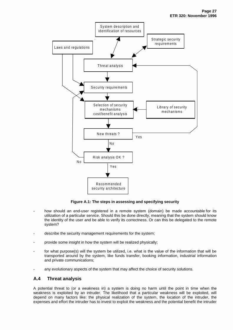
Figure A.1 illustrates all the steps in the process of specifying security for a given system.
A.1 Strategic security requirements
As a starting point for the development of secure IN systems, the following strategic security requirementscan be stated:
- the information exchanged between any pair of IN entities shall be correct;
- IN functions and information shall be available when needed;
- the user of a given IN service shall be accountable for it;
- information exchanged between IN entities shall be kept confidential when needed;
- security violations shall be detected and reported;
- ensure that lawful interception of user communications is possible and in accordance with tonational laws.
These strategic requirements will be a guide for the identification of all important threats as anintermediate step in specifying security.
A.2 Regulations
European laws and regulations will have several effects on the security requirements. In most countries itis required to protect the privacy of users. That means that information related to users stored within theIN network or being transferred across the network, need to be kept confidential. The use of cryptographicmethods may not be restricted in some countries, while in others are prohibited or severely restricted.Provisional guidelines can be found in the European Union document "Amended proposal for a councildirective on the protection of individuals with regard to the processing of personal data and on the freemovement of such data (SYN 287, 1992)". For IN, special concerns in this respect should be paid to thecontents of personal data stored in the SDF and transported from and to the SDF. If the evolving conceptsof ONP is being implemented, it will require that certain interfaces are openly accessible, and henceincrease the need for security.
A.3 System description
Describe the architecture and functions of the system, focusing on the following properties:
- functional description of each system component and its interface(s). It will be useful to distinguishbetween generic and service specific functionality and between intra-domain and inter-domainfunctionality;
- what kind of information is stored where in the system, either permanently or temporarily, and itsimportance to the correct functioning (integrity) of the system and to the privacy requirements of thesystem's subscribers and users;
- the sequence and meaning of the information flows between the system components;
- identify the borders of responsibilities with respect to system management and service provision;
- describe the customers of the services offered by the system, i.e. other service providers,subscribers and end-users, and their access rights to functions and information in the system (theaccess policy);
- identify and describe the level of trust between co-operating IN provider systems and how disputesabout service offerings and service usage should be resolved, i.e. the need for trusted third party toprovide a non-repudiation service.
Page 27ETR 320: November 1996
S y stem de scrip tion andid entif ica tion o f resou rc es
S trateg ic se cu rityreq uirem en ts
L aw s a nd re gu la tio ns
T hre at a na lys is
S ec uri ty r equire m en ts
S e lec tion o f se cu rityme ch an ism s
cos t/bene fi t a na lys is
L ib ra ry of s ecur it ym ech an ism s
N ew th rea ts ?Y es
N o
R isk a na lys is O K ?
Y esN o
R e co mm ende dsecu rity arch itec tu re
Figure A.1: The steps in assessing and specifying security
- how should an end-user registered in a remote system (domain) be made accountable for itsutilization of a particular service. Should this be done directly, meaning that the system should knowthe identity of the user and be able to verify its correctness. Or can this be delegated to the remotesystem?
- describe the security management requirements for the system;
- provide some insight in how the system will be realized physically;
- for what purpose(s) will the system be utilized, i.e. what is the value of the information that will betransported around by the system, like funds transfer, booking information, industrial informationand private communications;
- any evolutionary aspects of the system that may affect the choice of security solutions.
A.4 Threat analysis
A potential threat to (or a weakness in) a system is doing no harm until the point in time when theweakness is exploited by an intruder. The likelihood that a particular weakness will be exploited, willdepend on many factors like: the physical realization of the system, the location of the intruder, theexpenses and effort the intruder has to invest to exploit the weakness and the potential benefit the intruder

Page 28ETR 320: November 1996
can gain by his action (or in the negative sense the amount of damage done to the system). The latter willstrongly depend upon the applications the system is used for.
Hence a careful analysis of all the threats that can be identified should be performed, ranging the threatsin order of importance. This may be difficult, since the various aspects of costs can only be roughlyestimated. In evaluating each potential threat, an attempt should be made to characterize it according to:
- the likelihood that a weakness will be detected. This will to some extent depend upon the location ofthe intruder relative to the weakness;
- the cost and effort involved in exploiting the weakness;
- the potential benefit gained by the intruder in exploiting the weakness;
- the potential damage that can be done to the system and its actors (and its subscribers/users).
A.5 Security requirements
Based on the ordered list of threats, the security requirements can be specified, i.e. to convert threats intorequirements. In addition, security requirements imposed by the Commission of the EU and by nationallegislation's and regulations in the various European countries need to be taken into account.
A.6 Selection of security mechanisms and cost/benefit analysis
In order to perform this step in the assessment and specification process a library of security mechanismsis assumed, ordered according to the security services they can be involved in:
for each security service,do describe all applicable security mechanisms and their figures of merit like:- effect on system performance;- effect on user friendliness;- cost of implementation;- cost of management.
For each security requirement, perform a cost/benefit analysis to select the most cost effective securitymechanism to counteract the threat. Cost means not only the real costs, but in a broader sense, also theside-effects on performance, user friendliness, etc. The choice of security mechanisms will also beaffected by national legislation and regulations. The potential damage and economical loss the providermay experience when the weakness in the system is being exploited is not incorporated at this stage. Butthis should be taken into account by the relevant parties themselves.
As a side-effect new threats may be created in the process of selecting the proper security mechanisms:
if new and significant threats were introduced in the selection process,go back to Threats Analysis and update the list of threats,then proceed from Security Requirements ,
A.7 Risk analysis
Normally at this stage, there are some residual threats left, which have not been accounted for.
Based on the known residual threats, a risk assessment needs to be performed to provide an estimate ofthe potential economical damage to the service provider and the loss of reputation if the integrity of hissystem and services are being compromised:
if the risk is not acceptable,go back to Security Requirements and update the security requirements;then proceed from Selection of Security Mechanisms .

Page 29ETR 320: November 1996
A.8 The security architecture and security management
The result of this step-wise approach will be a set of security mechanisms. These have to be integratedinto a coherent security architecture as part of the IN architecture. It may also be necessary to provide aguideline to this architecture, in line with what has been done in Information Technology SecurityEvaluation Criteria (ITSEC). Having the security architecture in place, the means to manage the varioussecurity elements of the system can then be developed. It needs to be kept in mind that a European-widesystem comprises many individually managed provider systems that to a large extent are autonomouswith respect to security.

Page 30ETR 320: November 1996
Annex B: Detailed description of the IN system
This annex provides a functional description of the IN system and each of its component, taken fromITU-T Recommendation Q.1214 [13] and ETR 319 [4].
B.1 General functional description
It is worth mentioning that the architecture is not yet in its final form, and therefore may change with time.Figure B.1 depicts the main components of the CS2 architecture and their relationships. The scope of thefunctionality is to provide:
- end user access to call/service processing;
- service invocation and control;
- end user interaction with service control;
- IN management;
- inter-working between service processing functional entities.
S C F SD F
D omain border
SC U AF
C C AF
SS F
C C F
SR F
D omain bo rderS C F SD F
O SF
SC AF
C C A F
SS F
C C F C C F
CCAF: Call Control Agent FunctionSCAF: Service Control Agent FunctionSCUAF: Service Control User Agent FunctionCCF: Call Control Function
SCF: Service Control FunctionSDF: Service Data FunctionSRF: Service Switching FunctionOSF: Operations System Function
NOTE 1: IWF has been left out to simplify the figure.
NOTE 2: The OSF consists of S-OSF, N-OSF and Network Element - Operations System Function(NE-OSF) and has a relationship to every functional elements in its domain.
Figure B.1: IN distributed functional plane model for CS2
B.1.1 End user access
End user can access IN functionality via various means, like analogue line interfaces, Integrated ServicesDigital Network (ISDN) Basic Rate Interface (BRI) or Primary Rate Interface (PRI), Public Land MobileNetwork (PLMN) mobile access, private network access, Broadband Integrated Services Digital Network(B-ISDN) customer or trunk access, or traditional trunk and Signalling System No.7 (SS7) interfaces.

Page 31ETR 320: November 1996
B.1.2 Service invocation and control
Call/service processing for CS2 builds upon the current call processing infrastructure of existing digitalexchanges. It does so by using a generic model of existing call control functionality to process basic two-party calls, then adding service switching functionality to invoke and manage IN service features. Onceinvoked, IN service features are executed under the control of service control functionality, in conjunctionwith service data functionality. With this distributed approach to call/service processing, the existing callcontrol functionality retains ultimate responsibility for the integrity of calls, as well as for the control of callprocessing resources.
There will be a set of constraints that apply to CS2, including:
a) CCF and SSF are tightly coupled, hence no relationship between those entities is standardized inCS2;
b) a call can be initiated by an end user or by a SCF on behalf of an end user;
c) a call may span multiple exchanges.
B.1.3 End user interaction with service control
End user interaction with the network to send and receive information is provided by service switching andcall control resources, augmented by specialized resources. These specialized resources are controlledby service control functionality, and are connected to end users via call control and service switchingfunctionality.
B.1.4 IN management
IN management functionality will be used to provide and manage service creation, the service controlfunctionality, service data functionality, specialized resource functionality and the combined serviceswitching/call control functionality in the network, outside the context of call/service processing. The INmanagement functions are modelled according to the TMN functional architecture. The end user mayaccess the management facilities via a direct link to TMN systems, or as part of management featuresimplemented in the SCF service logic. The entity OSF in figure B.1 should be seen to represent the fullTMN capability, including Element Management, Network Management and Service Managementfunctionality (E-OSF, N-OSF and S-OSF, respectively). IN management is described in more detail in themain part of this ETR.
B.1.5 Inter working between service processing functional entities
Service features, distributed over different service processing entities, may interwork/co-operate toprovide a service to an end user. This can be the case when a service spans multiple networks or when aspecific feature of a service is distributed in the network, for example for performance reasons. Althoughdifferent service processing entities may be involved at the same time for one service, at any time onlyone service processing entity controls the call processing resources. The main part of this ETR deals withinterworking in more detail.
B.2 Functional description of each component
B.2.1 CCAF
CCAF is the Call Control Agent (CCA) function that provides access for users. It is the interface betweenuser and network Call Control Functions (CCF). It:
a) provides for user access, interacting with the user to establish, maintain, modify and release, asrequired, a call or instance of service;
b) accesses the service-providing capabilities of the Call Control Function (CCF), using servicerequests (i.e. set-up, transfer, hold etc.) for the establishment, manipulation and release of a call orinstances of service;

Page 32ETR 320: November 1996
c) receives indications relating to the call or service from the CCF and relays them to the user asrequired;
d) maintains call/service state information as perceived by this functional entity.
B.2.2 CCF
CCF is the call control function in the network that provides call/connection processing and control. It:
a) establishes, manipulates and releases call/connection as "requested" by CCAF;
b) provides the capability to associate and relate CCAF functional entities that are involved in aparticular call and/or connection instance (that may be due to SSF requests);
c) manages the relationship between CCAF functional entities involved in a call (e.g. supervizes theoverall perspective of the call and/or connection instance);
d) provides trigger mechanisms to access IN functionality (e.g. passes events to the SSF).
B.2.3 SSF
SSF is the service switching function, which, associated with the CCF, provides the set of functionsrequired for interaction between the CCF and a SCF. It:
a) extend the logic of the CCF to include recognition of service control triggers and to interact with theSCF;
b) manages signalling between the CCF and the SCF;
c) modifies call/connection processing functions (in the CCF) as required to process requests for INprovided service usage under the control of the SCF;
d) for mobile subscribers, a handover procedure between SSFs may be required The SCF needs tobe aware when the handover takes place, either by requesting the handover or by receiving anindication. This will require a new type of event. If this should be possible for all phases of a call, isfor further study.
B.2.4 SCF
SCF is a function that commands call control functions in the processing of IN provided and/or customservice requests. The SCF may interact with other functional entities to access additional logic or to obtaininformation (service or user data) required to process a call/service logic instance. It:
a) interfaces and interacts with SSF/CCF, SRF, SCAF and SDF entities;
b) contains the logic and processing capability required to handle IN provided service attempts. Theseservice attempts can be either call associated or non-call associated (e.g. location updating orregistering of a mobile subscriber);
c) interacts with other SCFs, if necessary. Interaction with other SCFs is based on differentrequirements:
- different services, to resolve interaction between different services in different SCFs;
- one service, one service could span different SCFs because of network boundaries orbecause the service requires distributed control (e.g. relevant parts of the service aredistributed and a part of the network resources is allocated to their control);
- to provide access to the SSF/CCF capabilities to a different SCF, which can or may notaccess the SSF/CCF directly.

Page 33ETR 320: November 1996
B.2.5 SDF
SDF contains customer and network data for real time access by the SCF in the execution of an INprovided service. It:
a) interfaces and interacts with SCFs as required;
b) interfaces and interacts with other SDFs; this allows distribution of data management functionalityand location transparency for data manipulation. Access to data in the SDF from the SCF requiresno knowledge in the SCF with respect to the location of the data (distributed database functionality).
NOTE: The SDF contains data relating directly to the provision or operation of IN providedservices. Thus it does not necessarily encompass data provided by third party such ascredit information, but may provide access to these data.
Security on the SDF interface is provided by means of access rights, the SDF will verify the access rightsof an interacting SCF or SDF with respect to the accessed data.
The SDF is service independent in the same way as the SCF. When a new service is too be introduced,the SCF and the SDF are not functionally modified. or the SCF, the Service logic will contain the servicespecific part. For the SDF, the service specific part will be a Service data template. The SDF may providemore than data access, it can process functional requests from the SCF to process certain data.
To provide secure data access, unsuccessful comparisons can be monitored and data access can bedenied if too many unsuccessful attempts are detected. Also call record handling, billing, authenticationand security should be considered.
The SDF provides for the functionality required for distributed data management. this involves datalocation management for accessing data in another SDF and for distribution of data to other SDFs,maintaining data integrity for data which is distributed/copied to other SDFs. The security functions,required to enable secure access to distributed data, are also provided by the SDF.
B.2.6 SRF
SRF provides the specialized resources required for the execution of IN provided services (e.g. digitreceivers, announcements, conference bridges, protocol converters like fax or modem conversion, etc.).It:
a) interfaces and interacts with SCF and SSF (and with the CCF);
b) may contain the logic and processing capability to receive/send and convert information receivedfrom users;
c) may contain functionality similar to the CCF to manage bearer connections to the specializedresources.
B.2.7 SCUA
SCUA is the Service Control User Agent that provides access for users. It is the interface between userand network service control functions. It:
a) provides for user access, interacting with the user to establish, maintain, modify and release, asrequired, an instance of service;
b) accesses the service invocation capabilities of the SCAF, using service requests (e.g. locationregistration, attach, etc.) for the invocation of non-call associated services;
c) receives indications relating to non-call associated services from the SCAF and relays them to theuser as required;
d) maintains service state information as perceived by this functional entity.

Page 34ETR 320: November 1996
B.2.8 SCAF
SCAF is the function, which, associated with the Service Control User Agent Function (SCUAF), providesthe set of functions required for access and interaction between the user and a Service Control Function(SCF) for non-call associated services. It:
a) extends the logic of the SCUAF to include recognition of service control triggers and to interact withthe SCF;
b) manages/polices signalling between the SCUAF and the SCF;
c) receives indications relating to the service from the SCF and relays them to the SCUAF as required;
d) maintains call/service state information as perceived by this functional entity.

Page 35ETR 320: November 1996
Annex C: Threat analysis of the core INAP information flows
This annex provides an analysis of the information flows between IN entities from a security point of view.The analysis is based on Core INAP (ETS 300 374-1 [1]) and CS1 Distributed Functional Plane(ETR 318 [2]). INAP is a protocol that supports interactions between the following functional entitiesdefined in the IN model: SSF, SCF, SRF and SDF. OSF is not included. Note that Core INAP only coversCS1.
The meaning and importance of the various elements of the information flow are shown in table C.1. Themasquerading column indicates what the originator or recipient can gain by masquerading, e.g. a networkprovider could ask for call information from a competitor's SSF. Integrity threat indicates that thementioned party could benefit by altering the information in the operation (as opposed to reading theinformation as in content sensitivity). Identified roles are User, Subscriber, Service Provider (SP) andpublic or private NO. Content sensitivity is either high, medium or low, depending on the informationconveyed through the operation. The criteria for choosing the level of sensitivity has been the following: ifthe information contains private or confidential data, High sensitivity has been chosen; if the informationflow contains addresses, reference numbers or charging data, Medium sensitivity has been chosen; Lowsensitivity has been chosen for all release information and when no parameters are conveyed in theoperation.
Table C.1: Meaning and importance of the information flow components
Operation/Info flow Direction SensitivityMasqueradethreat from
Integritythreat from
Contentsensitivity
SCF ↔↔ SSFActivate Service Filtering SCF→SSF Originator SP Medium
(Charging &Addresses)
Activity Test SCF→SSF Recipient LowActivity Test Response(Return result from Activity Test)
SSF→SCF Originator Low
Apply Charging SCF→SSF Originator SubscriberUserSPNO
Medium(Charging)
Apply Charging Report SSF→SCF Originator SubscriberUserSPNO
Medium(Charging)
Call Gap SCF→SSF SPPNO
Medium(Addresses &Control)
Call Information Report SSF→SCF SPNO
Medium(Addresses &statistics)
Call Information Request SCF→SSF Originator LowCollect Information SCF→SSF LowConnect SCF→SSF Medium
(Addresses)Connect to Resource SCF→SSF Originator
RecipientSPNO
Medium(Addresses)
Continue SCF→SSF Originator LowDisconnect Forward Connection SCF→SSF Originator LowEstablish Temporary Connection SCF→SSF Originator? Medium
(Addresses)Event Notification Charging SSF→SCF Medium
(Charging)Event Report Basic Call StateModel (BCSM)
SSF→SCF Recipient Medium(Addresses)
(continued)

Page 36ETR 320: November 1996
Table C.1 (concluded): Meaning and importance of the information flow components
Operation/Info flow Direction SensitivityMasqueradethreat from
Integritythreat from
Contentsensitivity
SCF ↔↔ SSFFurnish Charging Information SCF→SSF Originator Medium
(Charging)Initial DP SSF→SCF Originator
RecipientMedium(Addresses)
Initiate Call Attempt SCF→SSF Originator Medium(Addresses)
Release Call SCF→SSF Originator Low(Cause)
Request Notification Charging Event SCF→SSF Originator Medium(ID's)
Request Report BCSM Event SCF→SSF Originator? Medium(ID's)
Reset Timer SCF→SSF Originator - Low(Medium)
Send Charging Information SCF→SSF Originator UserSubscriberSPNO
Medium(Charging)
Service Filtering Response SSF→SCF Recipient? - LowSCF ↔↔ SRFAssist Request Instructions SSF/SRF→SCF Originator? Low
(ID's)Cancel SCF→SRF Originator LowCollected User Information(Return result from Prompt andcollect user information)
SRF→SCF OriginatorRecipient
UserSubscriberSPNO
High(Data)
Play Announcement SCF→SRF Originator SPNO
Low(Control)
Prompt and collect user information SCF→SRF OriginatorRecipient
UserCustomerSPNO
High(Data)
Specialized Resource Report SRF→SCF - Low(Null)
SCF ↔↔ SDFUpdate SCF→SDF Originator
Recipient?UserSubscriberSPNO
High
Return Result from Update SDF→SCF RecipientOriginator?
Medium
Screen SCF→SDF OriginatorRecipient
UserSubscriberSPNO
High(Data)
Return Result from Screen SDF→SCF RecipientOriginator
UserSubscriberSPNO
High(Result)
Retrieve SCF→SDF OriginatorRecipient?
- Medium
Return Result from Retrieve SDF→SCF RecipientOriginator?
UserSubscriberSPNO
High
NOTE: The SCF-SDF relationship is not yet stable in Core INAP.
Page 37ETR 320: November 1996
Annex D: Bibliography
EU document SYN 287 (1992): "Amended proposal for a council directive on the protection ofindividuals with regard to the processing of personal data and on thefree movement of such data".

Page 38ETR 320: November 1996
History
Document history
November 1996 First Edition
ISBN 2-7437-1093-4Dépôt légal : Novembre 1996