EtherNet/IP Option Kit CM092 holes on the right side of the EtherNet/IP Option Card. e. Press the...
16
EtherNet/IP Option Kit CM092 Yaskawa America, Inc. – www.yaskawa.com IG.AFD.26, Page 1 of 16 Date: 08/18/2011 Rev: 11-08 Applicable products: Yaskawa F7U, G7U, P7U, E7U, G5M (Spec F), G5M(600V) and G5HHP drives. 1. Unpack the CM092 EtherNet/IP Option kit and verify that all components are present and undamaged. 2. Connect power to the Yaskawa AC drive and verify that the drive functions correctly. This includes running the drive from the operator keypad. Refer to the appropriate drive technical manual for information on connecting and operating the drive. 3. Remove power from the drive and wait for the charge lamp to be completely extinguished. Wait at least five additional minutes for the drive to be completely discharged. Measure the DC bus voltage and verify that it is at a safe level. 4. Remove the operator keypad and drive cover. a. Remove the operator keypad. b. Remove the terminal and control covers. c. Remove the option card hold-down by carefully compressing the top and bottom until it becomes free of its holder. Lift it out. 5. Mount the EtherNet/IP Option Card on the drive Note: Skip to step 6 for G5HHP drives. a. Connect the RJ-45 M-F cable supplied in this kit to the EtherNet/IP Option Card. b. Connect the ground wire supplied to ground terminal J6 on the EtherNet/ IP Option Card. c. Align the J2 connector on the back of the EtherNet/IP Option Card with its mating 2CN connector on the drive control card. d. Align the two standoffs on the front of the drive control board with the two holes on the right side of the EtherNet/IP Option Card. e. Press the EtherNet/IP Option Card firmly onto the drive 2CN connector and standoffs until the J2 connector is fully seated on 2CN and the drive standoffs have locked into their appropriate holes. f. Route the RJ-45 M-F cable and the ground wire along the left-inside of the AC drive enclosure. g. Replace the option card hold-down. h. Connect the ground wire from the option card terminal J6 to the terminal assembly ground connection. CM092 EtherNet/IP Option Kit Parts Qty. EtherNet/IP Option Card 1 Shielded RJ-45 M-F Cable 1 Ground Wire 1 4" x 1" Insulated Tubing 1 Cable Ties 2 MAC ID Label (Unique for each EtherNet/IP Option Card 1 Installation Guide (IG.AFD.26) 1 WARNING Dangerous voltages in excess of 400VDC (230V drives) or 800VDC (460V drives) are present at the DC bus terminals of the drive.
Transcript of EtherNet/IP Option Kit CM092 holes on the right side of the EtherNet/IP Option Card. e. Press the...
EtherNet/IP Option KitCM092
Applicable products: Yaskawa F7U, G7U, P7U, E7U, G5M (Spec F),G5M(600V) and G5HHP drives.1. Unpack the CM092 EtherNet/IP Option kit and verify that all
components are present and undamaged.
2. Connect power to the Yaskawa AC drive and verify that the drivefunctions correctly. This includes running the drive from the operator keypad. Refer to theappropriate drive technical manual for information on connecting andoperating the drive.
3. Remove power from the drive and wait for the charge lamp to becompletely extinguished. Wait at least five additional minutes for the drive to be completelydischarged. Measure the DC bus voltage and verify that it is at a safe level.
4. Remove the operator keypad and drive cover.a. Remove the operator keypad. b. Remove the terminal and control covers.c. Remove the option card hold-down by carefully
compressing the top and bottom until it becomes freeof its holder. Lift it out.
5. Mount the EtherNet/IP Option Card on the drive Note: Skip to step 6 for G5HHP drives.a. Connect the RJ-45 M-F cable supplied in this kit to the EtherNet/IP
Option Card.b. Connect the ground wire supplied to ground terminal J6 on the EtherNet/
IP Option Card.c. Align the J2 connector on the back of the EtherNet/IP Option Card with
its mating 2CN connector on the drive control card.d. Align the two standoffs on the front of the drive control board with the
two holes on the right side of the EtherNet/IP Option Card.e. Press the EtherNet/IP Option Card firmly onto the drive 2CN connector
and standoffs until the J2 connector is fully seated on 2CN and the drivestandoffs have locked into their appropriate holes.
f. Route the RJ-45 M-F cable and the ground wire along the left-inside ofthe AC drive enclosure.
g. Replace the option card hold-down.h. Connect the ground wire from the option card terminal J6 to the terminal
assembly ground connection.
CM092 EtherNet/IP Option Kit Parts Qty.EtherNet/IP Option Card 1Shielded RJ-45 M-F Cable 1Ground Wire 14" x 1" Insulated Tubing 1Cable Ties 2MAC ID Label (Unique for each EtherNet/IP Option Card 1Installation Guide (IG.AFD.26) 1
WARNINGDangerous voltages in excess of 400VDC (230V drives) or 800VDC (460V drives) are present at the DC bus terminals of the drive.
Yaskawa America, Inc. – www.yaskawa.comIG.AFD.26, Page 1 of 16
Date: 08/18/2011 Rev: 11-08
EtherNet/IP Option KitCM092
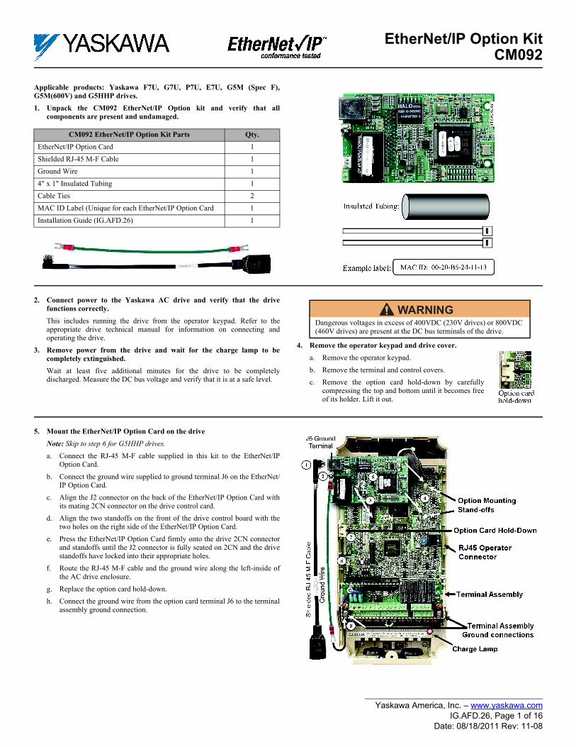
6. Mount the EtherNet/IP Option Card on the G5HHP drive.a. Attach the CM092 EtherNet/IP Option ground wire to the ground
terminal as shown. Make sure that the terminal is connected to a reliable,noise free ground.
b. Connect the CM092 EtherNet/IP Option card to the 2CN connector onthe master control board.
c. Secure the Cat-5 Ethernet cable to the support with a tie wrap to providestrain relief for the connector.
d. Attach the Ethernet cable to the CM092 EtherNet/IP Option card asshown.
e. Fully engage the stand-offs in the mounting holes on the card.f. Route the Ethernet cable away from any power wires within the cabinet.
When outside of the cabinet, run the Ethernet cable in its own conduit.However, it may be run along with low voltage signals such as feedbackwiring.
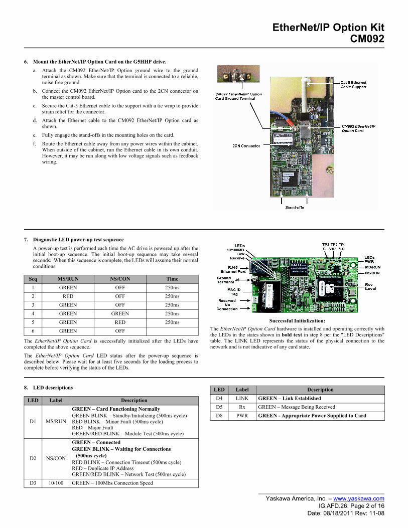
7. Diagnostic LED power-up test sequenceA power-up test is performed each time the AC drive is powered up after theinitial boot-up sequence. The initial boot-up sequence may take severalseconds. When this sequence is complete, the LEDs will assume their normalconditions.
The EtherNet/IP Option Card is successfully initialized after the LEDs havecompleted the above sequence.The EtherNet/IP Option Card LED status after the power-up sequence isdescribed below. Please wait for at least five seconds for the loading process tocomplete before verifying the status of the LEDs.
Successful Initialization:The EtherNet/IP Option Card hardware is installed and operating correctly withthe LEDs in the states shown in bold text in step 8 per the "LED Descriptions"table. The LINK LED represents the status of the physical connection to thenetwork and is not indicative of any card state.
8. LED descriptions
Seq MS/RUN NS/CON Time1 GREEN OFF 250ms2 RED OFF 250ms3 GREEN OFF 250ms4 GREEN GREEN 250ms5 GREEN RED 250ms6 GREEN OFF
LED Label Description
D1 MS/RUN
GREEN – Card Functioning NormallyGREEN BLINK – Standby/Initializing (500ms cycle)RED BLINK – Minor Fault (500ms cycle)RED – Major FaultGREEN/RED BLINK – Module Test (500ms cycle)
D2 NS/CON
GREEN – ConnectedGREEN BLINK – Waiting for Connections (500ms cycle)RED BLINK – Connection Timeout (500ms cycle)RED – Duplicate IP AddressGREEN/RED BLINK – Network Test (500ms cycle)
D3 10/100 GREEN – 100Mbs Connection Speed
D4 LINK GREEN – Link EstablishedD5 Rx GREEN – Message Being ReceivedD8 PWR GREEN - Appropriate Power Supplied to Card
LED Label Description
Yaskawa America, Inc. – www.yaskawa.comIG.AFD.26, Page 2 of 16
Date: 08/18/2011 Rev: 11-08

EtherNet/IP Option KitCM092
9. Connect to the EtherNet/IP Option Card. Note: Due to the presence of high voltage in the area of the network connection, insulating the RJ-45 M-F cable connection is required.a. Prior to connecting the RJ-45 M-F network cable, slide the supplied
insulated tubing (4"x1") over the female end of the supplied RJ-45 M-Fcable.1. Direct connection: To connect directly to the EtherNet/IP Option
Card, plug one end of a CAT-5 EtherNet/IP crossover cable into theRJ-45 socket on the supplied RJ-45 M-F cable. Connect the other
end to the RJ-45 EtherNet/IP socket on the configuration device,typically a controller, laptop or other PC.
2. Connection through hub or switch: To connect through a switch,hub or router, connect the RJ-45 socket on the RJ-45 M-F cable tothe switch, hub or router using a standard CAT-5 patch cable.
b. After the network connection is made, slide the insulated tubing (4"x1" Insulated Tubing) over the connection and secure it in place usingthe supplied cable ties.
10. Configure the EtherNet/IP network.a. The default configuration option for the EtherNet/IP Option Card is
DHCP (Dynamic Host Configuration Protocol). Thus there must be aDHCP Server connected to the network in order to have the IP address ofthe EtherNet/IP Option Card set. For detailed information on how to setup the Rockwell BOOTP/DHCP Server on a PC refer to the appropriateRockwell document or Yaskawa's Application Note AN.AFD.10.
b. If the network configuration requires that devices have a static IPaddress, the EtherNet/IP Option Card's configuration can be changed toUSER and the appropriate static IP address can be entered via theEtherNet/IP Option Card's web pages as shown below. Note that the EtherNet/IP Option Card must first have been assigned anIP address via DHCP before its configuration can be changed.
11. Configuring a PC with a static IP addressa. Select an existing connection or create a new network connection for communication with the EtherNet/IP Option Card.
1. Select Start ==> Settings ==> Network Connections from the task bar in the Windows OS.2. Select the network connection to be used.
b. Right click on the network connection and select Properties from the drop-down menu.c. Select Internet Protocol (TCP/IP) from the components displayed.
Note: If a TCP/IP selection is not available, it may be installed by selecting Install. Administrator access to the PC and the OS operating system installation CD-ROMs may also be required.
1. Select Properties.Note: If the PC is on a building or office network, disconnect it from that network before proceeding. Record the existing network settings. If the network connection already has an IP address assigned on the EtherNet/IP Local network, ignore the following instructions and just click on Cancel.
2. Select the Use the following IP address radio button.3. Enter the IP address of a vacant IP address on the EtherNet/IP Local Network (192.168.1.19 in this example).4. Enter the subnet mask for the EtherNet/IP Local Network (255.255.255.0 in this example).5. Check the system network schematic or with your network administrator to ensure that the IP address does not already exist on the network.6. Once the IP address and Subnet mask are entered, select OK.
Note: It may be necessary to reboot the PC in order for the changes to take effect.
12. Accessing the EtherNet/IP Option Card web pagesThe browser interface to the EtherNet/IP Option Card can be used for configuring the card or for network and drive information and diagnostics. To access the webpages:
a. Obtain the IP address of the desired drive and enter that IP address in the browser address bar. Hit Enter. The IP address of the desired drive is 192.168.1.20 inthis example. The main web page should be displayed.
IP address: 192.168.1.19
Subnet mask: 255.255.255.0
Yaskawa America, Inc. – www.yaskawa.comIG.AFD.26, Page 3 of 16
Date: 08/18/2011 Rev: 11-08

EtherNet/IP Option KitCM092
13. Configuring the EtherNet/IP Option Carda. Select Configuration from the main web page.b. After the Configuration page has been displayed, select the method in
which the EtherNet/IP Option Card will obtain its IP address.1. User: The EtherNet/IP Option Card will use the network address as
entered in the IP, Subnet and Gateway fields. Check with thesystem schematic or network administrator to insure that the IPaddress is valid and unique and that the subnet mask is correct.The USER radio button is used in this example. Enter the new IP address, 192.168.1.37 in this example.
2. DHCP: The EtherNet/IP Option Card will use the network addressassigned to it by the DHCP server.
3. BOOTP: The EtherNet/IP Option Card will use the network addressassigned to it by the BOOTP server.
c. Select the Gateway Usage. Connectivity to the EtherNet/IP Option Cardmay be limited or nonfunctional if the gateway usage setting and gatewayaddress do not match the network infrastructure in which it is installed.
1. Do not use default gateway in system. Select this radio button todisable the gateway when there is no external gateway in the system.
2. Use default gateway in system. Select this radio button to enablethe gateway when there is an external gateway in the system. Verifyand/or update the gateway address as necessary, so that it matchesthe address of the system gateway.
3. In all cases the Gateway field must contain a valid IP address andmust not be blank.
d. When the new configuration, IP address and subnet mask have beenentered, click the Submit button.
e. Verify that the information is correct on the Submit Results page.f. Power cycle the drive in order to store the new information on the
EtherNet/IP Option Card.g. Note: The IP address in the browser address bar will have to be changed
to the drive's new IP address and the web page refreshed in order tocontinue to communicate with the EtherNet/IP Option Card web pages.
Configuration: USERIP Address: 192.168.1.37Subnet mask: 255.255.255.0Enable Browser Interface Gateway Usage Disabled
Yaskawa America, Inc. – www.yaskawa.comIG.AFD.26, Page 4 of 16
Date: 08/18/2011 Rev: 11-08

EtherNet/IP Option KitCM092
14. Finish the EtherNet/IP Option Card installation.a. Remove power from the AC drive and wait for the charge lamp to be
completely extinguished. Wait at least five additional minutes for thedrive to be completely discharged. Measure the AC drive DC bus voltageand verify that it is at a safe level.
b. Reinstall all drive covers and the operator keypad. Apply power to thedrive.
c. Set parameters b1-01 and b1-02 to their appropriate values. Refer to the table to the right for available b1-01 and b1-02 values.
15. Resetting the EtherNet/IP Option Card to its default configurationThe factory default settings are as follows:
Configure Network Parameters: DHCPIP Address: 192.168.1.20Subnet: 255.255.255.0Gateway: 192.168.1.1
Symptom: The Yaskawa EtherNet/IP Option Card Main web page does notdisplay on the PC web browser screen. Corrective Action: Check that the PC is set up, properly connected and thatan IP address has been assigned to both the server and the node and that theyare on the same local network.If the web page is still not visible after confirming PC set up, then reset theconfiguration of the EtherNet/IP Option Card to its factory default asfollows:a. Remove power from the AC drive and wait for the charge lamp to be
completely extinguished. Wait at least five additional minutes for thedrive to be completely discharged. Measure the AC drive DC bus voltageand verify that it is at a safe level.
b. Place an insulated wire reset jumper between test points C and /LD onthe EtherNet/IP Option Card as shown in the figure to the right.
c. Reapply power to the AC drive and wait approximately 10 seconds forthe power-up cycle to complete.
d. Remove power from the AC drive and remove the jumper between C and/LD on the EtherNet/IP Option Card.
e. Reapply power to the AC drive and wait approximately 10 seconds forthe power-up sequence to complete.
16. Important notesa. It is strongly recommended that shielded CAT-5 patch or crossover cable
be used for all network cables. (Refer to step 9 above for the properselection of patch or crossover cable).
b. Switches implementing IGMP snooping are strongly recommended.When IGMP snooping is used, devices will only receive the multicastpackets in which they are interested.
c. The maximum number of simultaneous connections is: 1 for I/O, 4 forExplicit, 2 for Drive Wizard.
d. To simplify the drive configuration, EDS file can be obtained atwww.yaskawa.com. Select Downloads, By Inverter Drives, ByProduct, and Network Comms-Ethernet. Then select the appropriateEDS file based on the drive series and the latest version from those listed.EDS files for individual drive models are compressed into a single Zipfile and need to be un-zipped into a temporary directory in order to beinstalled.
e. Refer to the appropriate user, programming or parameter access manualfor a complete list of drive parameters and registers available. A list ofapplicable manuals is available at the end of this document.
WARNINGDangerous voltages in excess of 400VDC (230V drives) or 800VDC (460V drives) are present at the DC bus terminals of the drive.
Parameter Function Data Description Default
b1-01 Reference Source
0 Digital Operator
1
1 Terminal Strip
2 Built-in Modbus RTU RS-485 Terminals
3 Option Kit (EtherNet/IP Option)4 Pulse Input (F7 and G7 Only)
b1-02 RunSource
0 Digital Operator
11 Terminal Strip
2 Built-in Modbus RTU RS-485 Terminals
3 Option Kit (EtherNet/IP Option)
WARNINGDangerous voltages in excess of 400VDC (230V drives) or 800VDC (460V drives) are present at the DC bus terminals of the drive.
Yaskawa America, Inc. – www.yaskawa.comIG.AFD.26, Page 5 of 16
Date: 08/18/2011 Rev: 11-08
EtherNet/IP Option KitCM092
17. Drive labeling and EDS files
18. EtherNet/IP Option Card fault codes
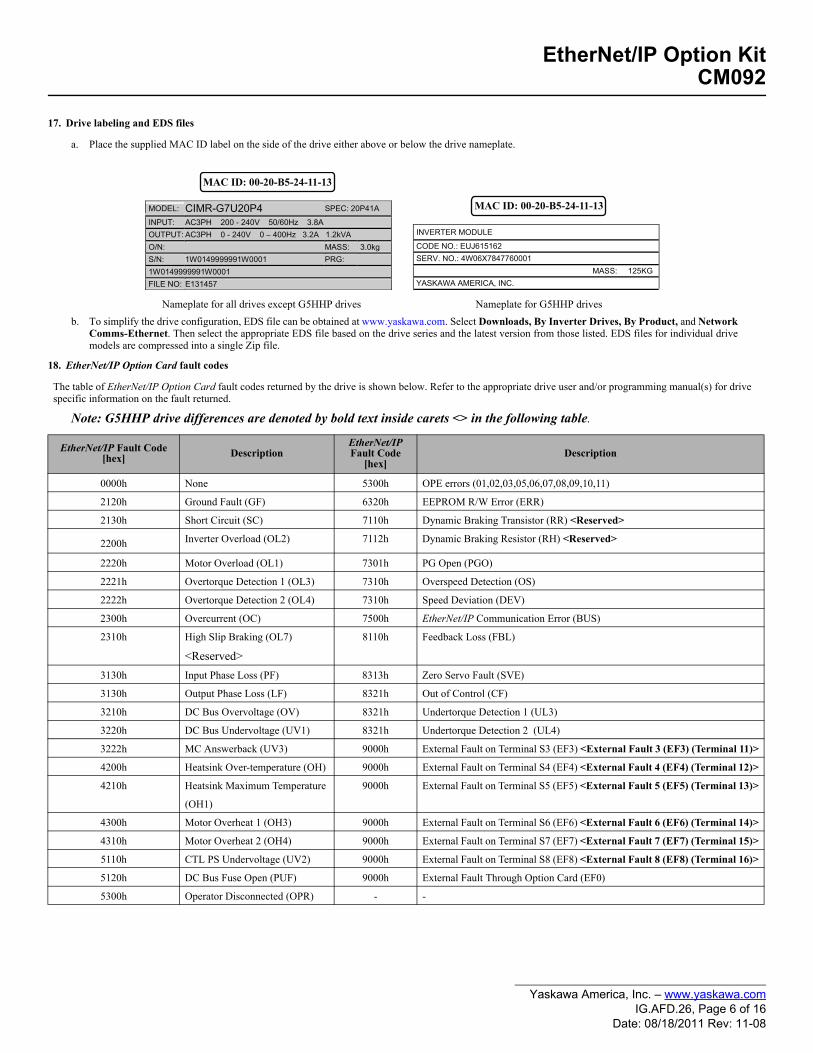
a. Place the supplied MAC ID label on the side of the drive either above or below the drive nameplate.
Nameplate for all drives except G5HHP drives Nameplate for G5HHP drivesb. To simplify the drive configuration, EDS file can be obtained at www.yaskawa.com. Select Downloads, By Inverter Drives, By Product, and Network
Comms-Ethernet. Then select the appropriate EDS file based on the drive series and the latest version from those listed. EDS files for individual drivemodels are compressed into a single Zip file.
MODEL: CIMR-G7U20P4 SPEC: 20P41A
INPUT: AC3PH 200 - 240V 50/60Hz 3.8A OUTPUT: AC3PH 0 - 240V 0 – 400Hz 3.2A 1.2kVA O/N: MASS: 3.0kg S/N: 1W0149999991W0001 PRG: 1W0149999991W0001 FILE NO: E131457
MAC ID: 00-20-B5-24-11-13
INVERTER MODULE
CODE NO.: EUJ615162SERV. NO.: 4W06X7847760001
MASS: 125KG YASKAWA AMERICA, INC.
MAC ID: 00-20-B5-24-11-13
The table of EtherNet/IP Option Card fault codes returned by the drive is shown below. Refer to the appropriate drive user and/or programming manual(s) for drive specific information on the fault returned.
Note: G5HHP drive differences are denoted by bold text inside carets <> in the following table.
EtherNet/IP Fault Code[hex] Description
EtherNet/IP Fault Code
[hex]Description
0000h None 5300h OPE errors (01,02,03,05,06,07,08,09,10,11)
2120h Ground Fault (GF) 6320h EEPROM R/W Error (ERR)
2130h Short Circuit (SC) 7110h Dynamic Braking Transistor (RR) <Reserved>
2200h Inverter Overload (OL2) 7112h Dynamic Braking Resistor (RH) <Reserved>
2220h Motor Overload (OL1) 7301h PG Open (PGO)
2221h Overtorque Detection 1 (OL3) 7310h Overspeed Detection (OS)
2222h Overtorque Detection 2 (OL4) 7310h Speed Deviation (DEV)
2300h Overcurrent (OC) 7500h EtherNet/IP Communication Error (BUS)
2310h High Slip Braking (OL7)
<Reserved>8110h Feedback Loss (FBL)
3130h Input Phase Loss (PF) 8313h Zero Servo Fault (SVE)
3130h Output Phase Loss (LF) 8321h Out of Control (CF)
3210h DC Bus Overvoltage (OV) 8321h Undertorque Detection 1 (UL3)
3220h DC Bus Undervoltage (UV1) 8321h Undertorque Detection 2 (UL4)
3222h MC Answerback (UV3) 9000h External Fault on Terminal S3 (EF3) <External Fault 3 (EF3) (Terminal 11)>
4200h Heatsink Over-temperature (OH) 9000h External Fault on Terminal S4 (EF4) <External Fault 4 (EF4) (Terminal 12)>
4210h Heatsink Maximum Temperature
(OH1)
9000h External Fault on Terminal S5 (EF5) <External Fault 5 (EF5) (Terminal 13)>
4300h Motor Overheat 1 (OH3) 9000h External Fault on Terminal S6 (EF6) <External Fault 6 (EF6) (Terminal 14)>
4310h Motor Overheat 2 (OH4) 9000h External Fault on Terminal S7 (EF7) <External Fault 7 (EF7) (Terminal 15)>
5110h CTL PS Undervoltage (UV2) 9000h External Fault on Terminal S8 (EF8) <External Fault 8 (EF8) (Terminal 16)>
5120h DC Bus Fuse Open (PUF) 9000h External Fault Through Option Card (EF0)
5300h Operator Disconnected (OPR) - -
Yaskawa America, Inc. – www.yaskawa.comIG.AFD.26, Page 6 of 16
Date: 08/18/2011 Rev: 11-08
EtherNet/IP Option KitCM092
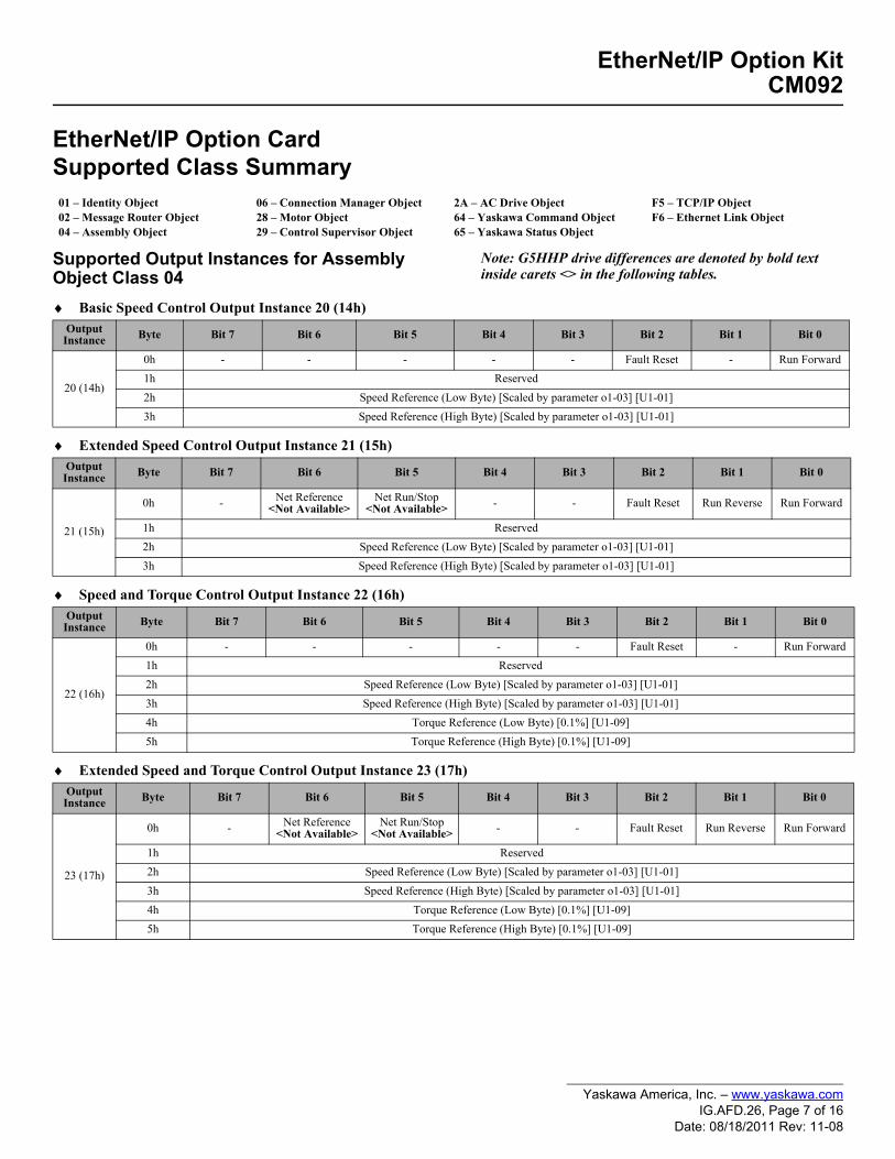
EtherNet/IP Option Card Supported Class Summary
Supported Output Instances for Assembly Object Class 04
Note: G5HHP drive differences are denoted by bold text inside carets <> in the following tables.
♦ Basic Speed Control Output Instance 20 (14h)
♦ Extended Speed Control Output Instance 21 (15h)
♦ Speed and Torque Control Output Instance 22 (16h)
♦ Extended Speed and Torque Control Output Instance 23 (17h)
01 – Identity Object02 – Message Router Object04 – Assembly Object
06 – Connection Manager Object28 – Motor Object29 – Control Supervisor Object
2A – AC Drive Object64 – Yaskawa Command Object65 – Yaskawa Status Object
F5 – TCP/IP ObjectF6 – Ethernet Link Object
Output Instance Byte Bit 7 Bit 6 Bit 5 Bit 4 Bit 3 Bit 2 Bit 1 Bit 0
20 (14h)
0h - - - - - Fault Reset - Run Forward1h Reserved 2h Speed Reference (Low Byte) [Scaled by parameter o1-03] [U1-01]3h Speed Reference (High Byte) [Scaled by parameter o1-03] [U1-01]
Output Instance Byte Bit 7 Bit 6 Bit 5 Bit 4 Bit 3 Bit 2 Bit 1 Bit 0
21 (15h)
0h - Net Reference<Not Available>
Net Run/Stop<Not Available> - - Fault Reset Run Reverse Run Forward
1h Reserved 2h Speed Reference (Low Byte) [Scaled by parameter o1-03] [U1-01]3h Speed Reference (High Byte) [Scaled by parameter o1-03] [U1-01]
Output Instance Byte Bit 7 Bit 6 Bit 5 Bit 4 Bit 3 Bit 2 Bit 1 Bit 0
22 (16h)
0h - - - - - Fault Reset - Run Forward1h Reserved 2h Speed Reference (Low Byte) [Scaled by parameter o1-03] [U1-01]3h Speed Reference (High Byte) [Scaled by parameter o1-03] [U1-01]4h Torque Reference (Low Byte) [0.1%] [U1-09]5h Torque Reference (High Byte) [0.1%] [U1-09]
Output Instance Byte Bit 7 Bit 6 Bit 5 Bit 4 Bit 3 Bit 2 Bit 1 Bit 0
23 (17h)
0h - Net Reference<Not Available>
Net Run/Stop <Not Available> - - Fault Reset Run Reverse Run Forward
1h Reserved2h Speed Reference (Low Byte) [Scaled by parameter o1-03] [U1-01]3h Speed Reference (High Byte) [Scaled by parameter o1-03] [U1-01]4h Torque Reference (Low Byte) [0.1%] [U1-09]5h Torque Reference (High Byte) [0.1%] [U1-09]
Yaskawa America, Inc. – www.yaskawa.comIG.AFD.26, Page 7 of 16
Date: 08/18/2011 Rev: 11-08

EtherNet/IP Option KitCM092
♦ Yaskawa Standard Speed/Torque Control Output Instance 101 (65h)
♦ Yaskawa Extended Speed/Torque Control Output Instance 115 (73h)
Output Instance Byte Bit 7 Bit 6 Bit 5 Bit 4 Bit 3 Bit 2 Bit 1 Bit 0
101 (65h)
0h Terminal S8<Terminal 16>
Terminal S7<Terminal 15>
Terminal S6<Terminal 14>
Terminal S5<Terminal 13>
Terminal S4<Terminal 12>
Terminal S3<Terminal 11>
Run
Reverse
Run Forward
1h Terminal M5-M6<Terminals 20-50>
Terminal M3-M4<Terminals 19-50>
Terminal M1-M2<Terminals 53-57> - - -
Fault
Reset
External
Fault2h Speed Reference (Low Byte) [Scaled by parameter o1-03] [U1-01]>3h Speed Reference (High Byte) [Scaled by parameter o1-03] [U1-01]4h Torque Reference (Low Byte) [0.1%] [U1-09]5h Torque Reference (High Byte) [0.1%] [U1-09]
6h Reserved <Torque Compensation (Low Byte) [0.1%]>
7h Reserved <Torque Compensation (High Byte) [0.1%]>
Output Instance Byte Bit 7 Bit 6 Bit 5 Bit 4 Bit 3 Bit 2 Bit 1 Bit 0
115 (73h)
0h Terminal S8<Terminal 16>
Terminal S7<Terminal 15>
Terminal S6<Terminal 14>
Terminal S5<Terminal 13>
Terminal S4 <Terminal 12>
Terminal S3 <Terminal 11>
Run Reverse
Run Forward
1h Terminal M5-M6<Terminals 20-50>
Terminal M3-M4<Terminals 19-50>
Terminal M1-M2<Terminals 53-57> - - - Fault
ResetExternal
Fault2h Speed Reference (Low Byte) [Scaled by parameter o1-03] [U1-01]3h Speed Reference (High Byte) [Scaled by parameter o1-03] [U1-01]4h Torque Reference (Low Byte) [0.1%] [U1-09]5h Torque Reference (High Byte) [0.1%] [U1-09]6h Torque Compensation (Low Byte) [0.1%]7h Torque Compensation (High Byte) [0.1%]
8h ~ Bh Reserved
Ch Analog Output Terminal FM (Low Byte) [-726 ~ +726 (-11VDC ~ +11VDC)]<Analog Input Terminal 36 (Low Byte)>
Dh Analog Output Terminal FM (High Byte) [-726 ~ +726 (-11VDC ~ +11VDC)]<Analog Input Terminal 36 (High Byte)>
Eh Analog Output Terminal AM (Low Byte) [-726 ~ +726 (-11VDC ~ +11VDC)]<Analog Input Terminal 39 (Low Byte)>
Fh Analog Output Terminal AM (High Byte) [-726 ~ +726 (-11VDC ~ +11VDC)]<Analog Input Terminal 39 (High Byte)>
10h Digital Output Terminal M1-M2 (Low Byte)<Digital Output (Low Byte) U1-11>
11h Digital Output Terminal M3-M4 (High Byte)<Digital Output (High Byte) U1-11>
12h ~ 13h Reserved
14h ~ 15h
Network Control (bit 0: Network Speed Reference, bit 1: Network Run Command) <Reserved>
16h ~ 27h Reserved
Yaskawa America, Inc. – www.yaskawa.comIG.AFD.26, Page 8 of 16
Date: 08/18/2011 Rev: 11-08
EtherNet/IP Option KitCM092
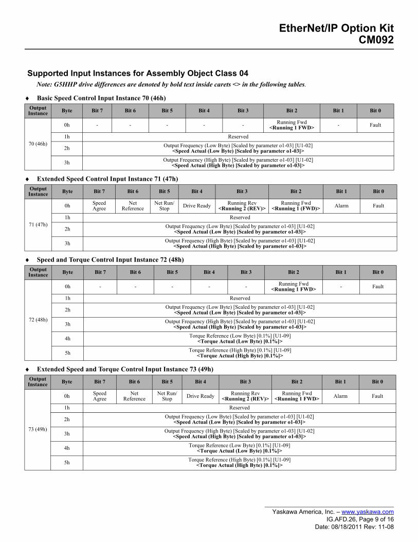
♦ Basic Speed Control Input Instance 70 (46h)
♦ Extended Speed Control Input Instance 71 (47h)
♦ Speed and Torque Control Input Instance 72 (48h)
♦ Extended Speed and Torque Control Input Instance 73 (49h)
Supported Input Instances for Assembly Object Class 04Note: G5HHP drive differences are denoted by bold text inside carets <> in the following tables.
Output Instance Byte Bit 7 Bit 6 Bit 5 Bit 4 Bit 3 Bit 2 Bit 1 Bit 0
70 (46h)
0h - - - - - Running Fwd<Running 1 FWD> - Fault
1h Reserved
2h Output Frequency (Low Byte) [Scaled by parameter o1-03] [U1-02]<Speed Actual (Low Byte) [Scaled by parameter o1-03]>
3h Output Frequency (High Byte) [Scaled by parameter o1-03] [U1-02]<Speed Actual (High Byte) [Scaled by parameter o1-03]>
Output Instance Byte Bit 7 Bit 6 Bit 5 Bit 4 Bit 3 Bit 2 Bit 1 Bit 0
71 (47h)
0h Speed Agree
Net Reference
Net Run/Stop Drive Ready Running Rev
<Running 2 (REV)>Running Fwd
<Running 1 (FWD)> Alarm Fault
1h Reserved
2h Output Frequency (Low Byte) [Scaled by parameter o1-03] [U1-02]<Speed Actual (Low Byte) [Scaled by parameter o1-03]>
3h Output Frequency (High Byte) [Scaled by parameter o1-03] [U1-02]<Speed Actual (High Byte) [Scaled by parameter o1-03]>
Output Instance Byte Bit 7 Bit 6 Bit 5 Bit 4 Bit 3 Bit 2 Bit 1 Bit 0
72 (48h)
0h - - - - - Running Fwd<Running 1 FWD> - Fault
1h Reserved
2h Output Frequency (Low Byte) [Scaled by parameter o1-03] [U1-02]<Speed Actual (Low Byte) [Scaled by parameter o1-03]>
3h Output Frequency (High Byte) [Scaled by parameter o1-03] [U1-02]<Speed Actual (High Byte) [Scaled by parameter o1-03]>
4h Torque Reference (Low Byte) [0.1%] [U1-09]<Torque Actual (Low Byte) [0.1%]>
5h Torque Reference (High Byte) [0.1%] [U1-09]<Torque Actual (High Byte) [0.1%]>
Output Instance Byte Bit 7 Bit 6 Bit 5 Bit 4 Bit 3 Bit 2 Bit 1 Bit 0
73 (49h)
0h Speed Agree
Net Reference
Net Run/Stop Drive Ready Running Rev
<Running 2 (REV)>Running Fwd
<Running 1 FWD> Alarm Fault
1h Reserved
2h Output Frequency (Low Byte) [Scaled by parameter o1-03] [U1-02]<Speed Actual (Low Byte) [Scaled by parameter o1-03]>
3h Output Frequency (High Byte) [Scaled by parameter o1-03] [U1-02]<Speed Actual (High Byte) [Scaled by parameter o1-03]>
4h Torque Reference (Low Byte) [0.1%] [U1-09]<Torque Actual (Low Byte) [0.1%]>
5h Torque Reference (High Byte) [0.1%] [U1-09]<Torque Actual (High Byte) [0.1%]>
Yaskawa America, Inc. – www.yaskawa.comIG.AFD.26, Page 9 of 16
Date: 08/18/2011 Rev: 11-08
EtherNet/IP Option KitCM092
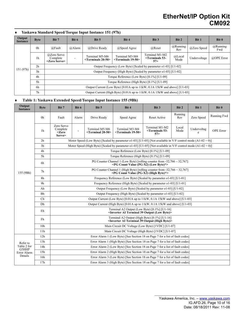
♦ Yaskawa Standard Speed/Torque Input Instance 151 (97h)
♦ Table 1: Yaskawa Extended Speed/Torque Input Instance 155 (9Bh)
Output Instance Byte Bit 7 Bit 6 Bit 5 Bit 4 Bit 3 Bit 2 Bit 1 Bit 0
151 (97h)
0h @Fault @Alarm @Drive Ready @Speed Agree @Reset @Running Rev @Zero Speed @Running
Fwd
1h@Zero Servo
Complete<Zero Servo>
- Terminal M5-M6<Terminals 20-50>
Terminal M3-M4<Terminals 19-50>
Terminal M1-M2<Terminals 53-
57>@Local Mode Undervoltage @OPE Error
2h Output Frequency (Low Byte) [Scaled by parameter o1-03] [U1-02]3h Output Frequency (High Byte) [Scaled by parameter o1-03] [U1-02]4h Torque Reference (Low Byte) [0.1%] [U1-09]5h Torque Reference (High Byte) [0.1%] [U1-09]6h Output Current (Low Byte) [0.01A up to 11kW, 0.1A 15kW and above] [U1-03]7h Output Current (High Byte) [0.01A up to 11kW, 0.1A 15kW and above] [U1-03]
Output Instance Byte Bit 7 Bit 6 Bit 5 Bit 4 Bit 3 Bit 2 Bit 1 Bit 0
155 (9Bh)
0h Fault Alarm Drive Ready Speed Agree Reset ActiveRunning
Rev Zero Speed Running Fwd
1hZero Servo Complete
<Zero Servo>
- Terminal M5-M6<Terminal 20-50>
Terminal M3-M4<Terminals 19-50>
Terminal M1-M2<Terminals 53-
57>
Local Mode Undervoltag
e OPE Error
2h Motor Speed (Low Byte) [Scaled by parameter o1-03] [U1-05] [Not available in V/F control mode (A1-02 = 0)]3h Motor Speed (High Byte) [Scaled by parameter o1-03] [U1-05] [Not available in V/F control mode (A1-02 = 0)]4h Torque Reference (Low Byte) [0.1%] [U1-09]5h Torque Reference (High Byte) [0.1%] [U1-09]
6h PG Counter Channel 1 (Low Byte) [rolling counter from -32,766 ~ 32,767]<PG Count Value (PG-X2) (Low Byte)*>
7h PG Counter Channel 1 (High Byte) [rolling counter from -32,766 ~ 32,767]<PG Count Value (PG-X2) (High Byte)*>
8h Frequency Reference (Low Byte) [Scaled by parameter o1-03] [U1-01]9h Frequency Reference (High Byte) [Scaled by parameter o1-03] [U1-01]Ah Output Frequency (Low Byte) [Scaled by parameter o1-03] [U1-02]Bh Output Frequency (High Byte) [Scaled by parameter o1-03] [U1-02]Ch Output Current (Low Byte) [0.01A up to 11kW, 0.1A 15kW and above] [U1-03]Dh Output Current (High Byte) [0.01A up to 11kW, 0.1A 15kW and above] [U1-03]
Eh Terminal A2 Output (Low Byte) [0.1%] [U1-16]<Inverter AI Terminal 39 Output (Low Byte)>
Fh Terminal A2 Output (High Byte) [0.1%] [U1-16]<Inverter AI Terminal 39 Output (High Byte)>
10h Main Circuit DC Voltage (Low Byte) [1VDC] [U1-07]11h Main Circuit DC Voltage (High Byte) [1VDC] [U1-07]
Refer to Table 2 for
G5HHP Error Alarm
Details
12h Error Alarm 1 (Low Byte) [See Section 18 on Page 7 for a list of fault codes]13h Error Alarm 1 (High Byte) [See Section 18 on Page 7 for a list of fault codes]14h Error Alarm 2 (Low Byte) [See Section 18 on Page 7 for a list of fault codes]15h Error Alarm 2 (High Byte) [See Section 18 on Page 7 for a list of fault codes]16h Error Alarm 3 (Low Byte) [See Section 18 on Page 7 for a list of fault codes]17h Error Alarm 3 (High Byte) [See Section 18 on Page 7 for a list of fault codes]
Yaskawa America, Inc. – www.yaskawa.comIG.AFD.26, Page 10 of 16
Date: 08/18/2011 Rev: 11-08

EtherNet/IP Option KitCM092
♦ Table 1: (continued) Yaskawa Extended Speed/Torque Input Instance 155
Table 1 Details: G5HHP bytes 12 to 17 for Instance 155 (9Bh)
Output Instance Byte Bit 7 Bit 6 Bit 5 Bit 4 Bit 3 Bit 2 Bit 1 Bit 0
155 (9Bh)
18h Terminal A3 Output (Low Byte) [0.1%] [U1-17]<Inverter AI Terminal 42 Input (Low Byte)>
19h Terminal A3 Output (High Byte) [0.1%] [U1-17]<Inverter AI Terminal 42 Input (High Byte)>
1Ah Digital Input Terminal Bit Field (Low Byte) [Terminals S1 ~ S8] [U1-10]<Inverter DI Terminals 9~16 Input (Low Byte)>
1Bh Digital Input Terminal Bit Field (High Byte) [Terminals S1 ~ S8] [U1-10]<Inverter DI Terminals 9~16 Input (High Byte)>
1Ch Terminal A1 Output (Low Byte) [0.1%] [U1-15]<Inverter AI Terminal 36 Input (Low Byte)>
1Dh Terminal A1 Output (High Byte) [0.1%] [U1-15]<Inverter AI Terminal 36 Input (High Byte)>
1Eh PG Counter Channel 2 (Low Byte) [rolling counter from -32,766 ~ 32,767]<PG Counter (Ch2) (PG-W2) (Low Byte)**>
1Fh PG Counter Channel 2 (High Byte) [rolling counter from -32,766 ~ 32,767]<PG Counter (Ch2) (PG-W2) (High Byte)**>
20h Drive Software Number (U1-14)<Reserved>
21h ~ 27h Reserved
* Encoder pulse count from PG-X2 option when in flux vector mode. There is no associated drive parameter** Encoder pulse count from PG-W2 option when in flux vector mode and using motor 2. Speed detection PG counter value.
Reference details in Table 1: Yaskawa Extended Speed/Torque Input Instance 155 (9Bh) for G5HHP drives bytes 12 to 17.Bytes 12 (Low) and 13 (High) -
Error Alarm Signal 1Bytes 14 (Low) and 15 (High) -
Error Alarm Signal 2Bytes 16 (Low) and 17 (High) -
Error Alarm Signal 3
Bit Fault Bit Fault Bit Fault
0h PUF DC Bus Fuse Open 0h EF3 External Fault - Terminal 11 0h CE Modbus Communication Error
1h UV1 DC Bus Undervoltage 1h EF4 External Fault - Terminal 12 1h BUS EtherNet/IP Bus Fault
2h UV2 Control Circuit Undervoltage 2h EF5 External Fault - Terminal 13 2h <Reserved>
3h UV3 Main Circuit Contactor Answerback Fault 3h EF6 External Fault - Terminal 14 3h <Reserved>
4h <Reserved> 4h EF7 External Fault - Terminal 15 4h CF Out of Control FaultNo Determination of Motor Speed
5h GF Ground Fault 5h EF8 External Fault - Terminal 16 5h SVE Zero Servo Fault (Closed loop flux vector only)
6h OC Overcurrent Fault 6h <Reserved> 6h EF0 External Communications Fault
7h OV Overvoltage Fault 7h OS Overspeed Fault 7h <Reserved>
8h OH Heatsink Over Temperature Fault 8h DEV Speed Deviation Fault 8h <Reserved>
9h OH1 Drive Overheat Fault 9h PGO PG Open, Encoder (Pulse Generator open circuit) 9h <Reserved>
Ah OL1 Motor Overload Fault Ah PF Input Phase Loss Fault Ah <Reserved>
Bh OL2 Drive Overload Fault Bh LF Output Phase Loss Bh <Reserved>
Ch OL3 Overtorque Fault 1 (L6-02) Ch <Reserved> Ch <Reserved>
Dh OL4 Overtorque Fault 2 (L6-05) Dh OPR Operator Disconnected Dh <Reserved>
Eh RR Not possible in HHP Eh ERR EEPROM R/W Error Eh <Reserved>
Fh RH Not possible in HHP Fh <Reserved> Fh <Reserved>
Yaskawa America, Inc. – www.yaskawa.comIG.AFD.26, Page 11 of 16
Date: 08/18/2011 Rev: 11-08
EtherNet/IP Option KitCM092
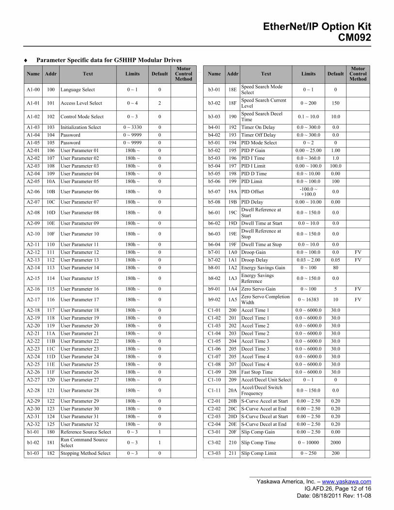
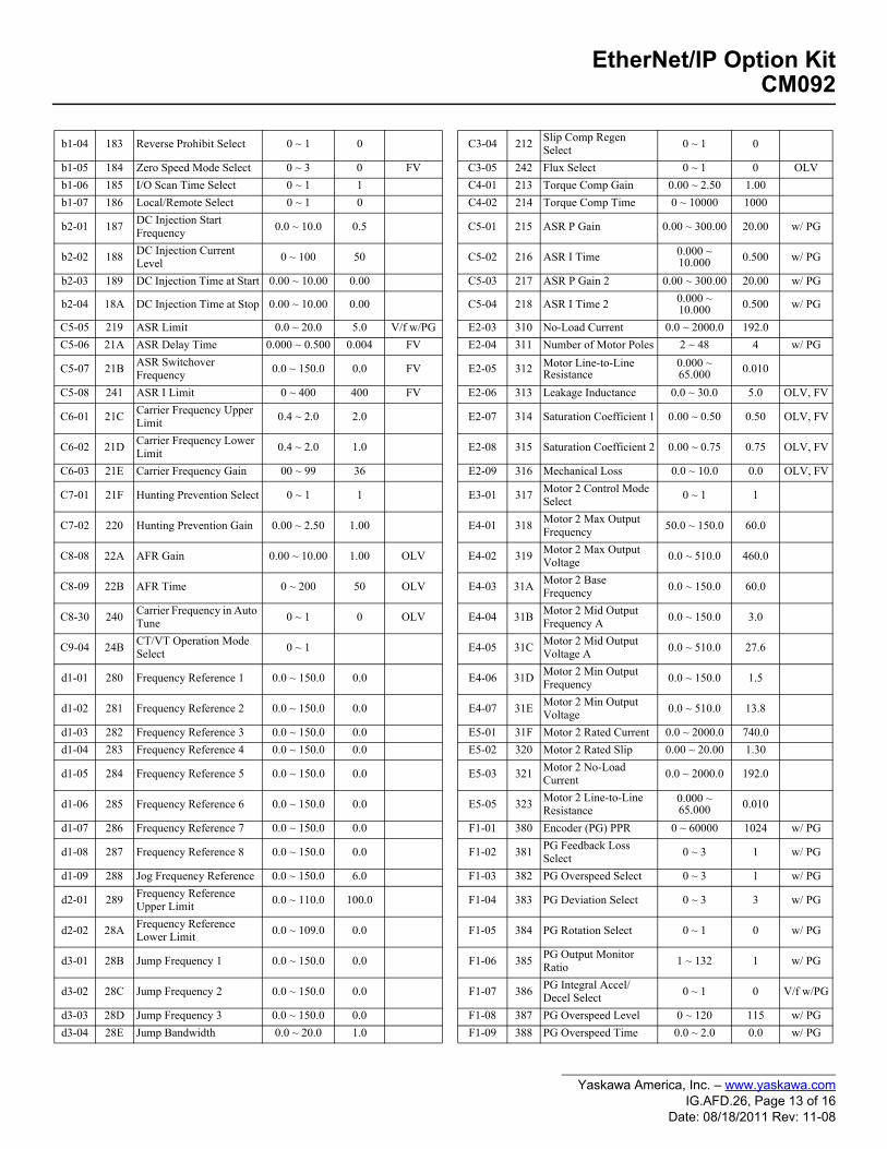
♦ Parameter Specific data for G5HHP Modular Drives
Name Addr Text Limits DefaultMotor
ControlMethod
_
_Name Addr Text Limits Default
MotorControlMethod
A1-00 100 Language Select 0 ~ 1 0 b3-01 18E Speed Search Mode Select 0 ~ 1 0
A1-01 101 Access Level Select 0 ~ 4 2 b3-02 18F Speed Search Current Level 0 ~ 200 150
A1-02 102 Control Mode Select 0 ~ 3 0 b3-03 190 Speed Search Decel Time 0.1 ~ 10.0 10.0
A1-03 103 Initialization Select 0 ~ 3330 0 b4-01 192 Timer On Delay 0.0 ~ 300.0 0.0A1-04 104 Password 0 ~ 9999 0 b4-02 193 Timer Off Delay 0.0 ~ 300.0 0.0A1-05 105 Password 0 ~ 9999 0 b5-01 194 PID Mode Select 0 ~ 2 0A2-01 106 User Parameter 01 180h ~ 0 b5-02 195 PID P Gain 0.00 ~ 25.00 1.00A2-02 107 User Parameter 02 180h ~ 0 b5-03 196 PID I Time 0.0 ~ 360.0 1.0A2-03 108 User Parameter 03 180h ~ 0 b5-04 197 PID I Limit 0.00 ~ 100.0 100.0A2-04 109 User Parameter 04 180h ~ 0 b5-05 198 PID D Time 0.0 ~ 10.00 0.00A2-05 10A User Parameter 05 180h ~ 0 b5-06 199 PID Limit 0.0 ~ 100.0 100
A2-06 10B User Parameter 06 180h ~ 0 b5-07 19A PID Offset -100.0 ~ +100.0 0.0
A2-07 10C User Parameter 07 180h ~ 0 b5-08 19B PID Delay 0.00 ~ 10.00 0.00
A2-08 10D User Parameter 08 180h ~ 0 b6-01 19C Dwell Reference at Start 0.0 ~ 150.0 0.0
A2-09 10E User Parameter 09 180h ~ 0 b6-02 19D Dwell Time at Start 0.0 ~ 10.0 0.0
A2-10 10F User Parameter 10 180h ~ 0 b6-03 19E Dwell Reference at Stop 0.0 ~ 150.0 0.0
A2-11 110 User Parameter 11 180h ~ 0 b6-04 19F Dwell Time at Stop 0.0 ~ 10.0 0.0A2-12 111 User Parameter 12 180h ~ 0 b7-01 1A0 Droop Gain 0.0 ~ 100.0 0.0 FVA2-13 112 User Parameter 13 180h ~ 0 b7-02 1A1 Droop Delay 0.03 ~ 2.00 0.05 FVA2-14 113 User Parameter 14 180h ~ 0 b8-01 1A2 Energy Savings Gain 0 ~ 100 80
A2-15 114 User Parameter 15 180h ~ 0 b8-02 1A3 Energy Savings Reference 0.0 ~ 150.0 0.0
A2-16 115 User Parameter 16 180h ~ 0 b9-01 1A4 Zero Servo Gain 0 ~ 100 5 FV
A2-17 116 User Parameter 17 180h ~ 0 b9-02 1A5 Zero Servo Completion Width 0 ~ 16383 10 FV
A2-18 117 User Parameter 18 180h ~ 0 C1-01 200 Accel Time 1 0.0 ~ 6000.0 30.0A2-19 118 User Parameter 19 180h ~ 0 C1-02 201 Decel Time 1 0.0 ~ 6000.0 30.0A2-20 119 User Parameter 20 180h ~ 0 C1-03 202 Accel Time 2 0.0 ~ 6000.0 30.0A2-21 11A User Parameter 21 180h ~ 0 C1-04 203 Decel Time 2 0.0 ~ 6000.0 30.0A2-22 11B User Parameter 22 180h ~ 0 C1-05 204 Accel Time 3 0.0 ~ 6000.0 30.0A2-23 11C User Parameter 23 180h ~ 0 C1-06 205 Decel Time 3 0.0 ~ 6000.0 30.0A2-24 11D User Parameter 24 180h ~ 0 C1-07 205 Accel Time 4 0.0 ~ 6000.0 30.0A2-25 11E User Parameter 25 180h ~ 0 C1-08 207 Decel Time 4 0.0 ~ 6000.0 30.0A2-26 11F User Parameter 26 180h ~ 0 C1-09 208 Fast Stop Time 0.0 ~ 6000.0 30.0A2-27 120 User Parameter 27 180h ~ 0 C1-10 209 Accel/Decel Unit Select 0 ~ 1 0
A2-28 121 User Parameter 28 180h ~ 0 C1-11 20A Accel/Decel Switch Frequency 0.0 ~ 150.0 0.0
A2-29 122 User Parameter 29 180h ~ 0 C2-01 20B S-Curve Accel at Start 0.00 ~ 2.50 0.20A2-30 123 User Parameter 30 180h ~ 0 C2-02 20C S-Curve Accel at End 0.00 ~ 2.50 0.20A2-31 124 User Parameter 31 180h ~ 0 C2-03 20D S-Curve Decel at Start 0.00 ~ 2.50 0.20A2-32 125 User Parameter 32 180h ~ 0 C2-04 20E S-Curve Decel at End 0.00 ~ 2.50 0.20b1-01 180 Reference Source Select 0 ~ 3 1 C3-01 20F Slip Comp Gain 0.00 ~ 2.50 0.00
b1-02 181 Run Command Source Select 0 ~ 3 1 C3-02 210 Slip Comp Time 0 ~ 10000 2000
b1-03 182 Stopping Method Select 0 ~ 3 0 C3-03 211 Slip Comp Limit 0 ~ 250 200
Yaskawa America, Inc. – www.yaskawa.comIG.AFD.26, Page 12 of 16
Date: 08/18/2011 Rev: 11-08
EtherNet/IP Option KitCM092
b1-04 183 Reverse Prohibit Select 0 ~ 1 0 C3-04 212 Slip Comp Regen Select 0 ~ 1 0
b1-05 184 Zero Speed Mode Select 0 ~ 3 0 FV C3-05 242 Flux Select 0 ~ 1 0 OLVb1-06 185 I/O Scan Time Select 0 ~ 1 1 C4-01 213 Torque Comp Gain 0.00 ~ 2.50 1.00b1-07 186 Local/Remote Select 0 ~ 1 0 C4-02 214 Torque Comp Time 0 ~ 10000 1000
b2-01 187 DC Injection Start Frequency 0.0 ~ 10.0 0.5 C5-01 215 ASR P Gain 0.00 ~ 300.00 20.00 w/ PG
b2-02 188 DC Injection Current Level 0 ~ 100 50 C5-02 216 ASR I Time 0.000 ~
10.000 0.500 w/ PG
b2-03 189 DC Injection Time at Start 0.00 ~ 10.00 0.00 C5-03 217 ASR P Gain 2 0.00 ~ 300.00 20.00 w/ PG
b2-04 18A DC Injection Time at Stop 0.00 ~ 10.00 0.00 C5-04 218 ASR I Time 2 0.000 ~ 10.000 0.500 w/ PG
C5-05 219 ASR Limit 0.0 ~ 20.0 5.0 V/f w/PG E2-03 310 No-Load Current 0.0 ~ 2000.0 192.0C5-06 21A ASR Delay Time 0.000 ~ 0.500 0.004 FV E2-04 311 Number of Motor Poles 2 ~ 48 4 w/ PG
C5-07 21B ASR Switchover Frequency 0.0 ~ 150.0 0.0 FV E2-05 312 Motor Line-to-Line
Resistance0.000 ~ 65.000 0.010
C5-08 241 ASR I Limit 0 ~ 400 400 FV E2-06 313 Leakage Inductance 0.0 ~ 30.0 5.0 OLV, FV
C6-01 21C Carrier Frequency Upper Limit 0.4 ~ 2.0 2.0 E2-07 314 Saturation Coefficient 1 0.00 ~ 0.50 0.50 OLV, FV
C6-02 21D Carrier Frequency Lower Limit 0.4 ~ 2.0 1.0 E2-08 315 Saturation Coefficient 2 0.00 ~ 0.75 0.75 OLV, FV
C6-03 21E Carrier Frequency Gain 00 ~ 99 36 E2-09 316 Mechanical Loss 0.0 ~ 10.0 0.0 OLV, FV
C7-01 21F Hunting Prevention Select 0 ~ 1 1 E3-01 317 Motor 2 Control Mode Select 0 ~ 1 1
C7-02 220 Hunting Prevention Gain 0.00 ~ 2.50 1.00 E4-01 318 Motor 2 Max Output Frequency 50.0 ~ 150.0 60.0
C8-08 22A AFR Gain 0.00 ~ 10.00 1.00 OLV E4-02 319 Motor 2 Max Output Voltage 0.0 ~ 510.0 460.0
C8-09 22B AFR Time 0 ~ 200 50 OLV E4-03 31A Motor 2 Base Frequency 0.0 ~ 150.0 60.0
C8-30 240 Carrier Frequency in Auto Tune 0 ~ 1 0 OLV E4-04 31B Motor 2 Mid Output
Frequency A 0.0 ~ 150.0 3.0
C9-04 24B CT/VT Operation Mode Select 0 ~ 1 E4-05 31C Motor 2 Mid Output
Voltage A 0.0 ~ 510.0 27.6
d1-01 280 Frequency Reference 1 0.0 ~ 150.0 0.0 E4-06 31D Motor 2 Min Output Frequency 0.0 ~ 150.0 1.5
d1-02 281 Frequency Reference 2 0.0 ~ 150.0 0.0 E4-07 31E Motor 2 Min Output Voltage 0.0 ~ 510.0 13.8
d1-03 282 Frequency Reference 3 0.0 ~ 150.0 0.0 E5-01 31F Motor 2 Rated Current 0.0 ~ 2000.0 740.0d1-04 283 Frequency Reference 4 0.0 ~ 150.0 0.0 E5-02 320 Motor 2 Rated Slip 0.00 ~ 20.00 1.30
d1-05 284 Frequency Reference 5 0.0 ~ 150.0 0.0 E5-03 321 Motor 2 No-Load Current 0.0 ~ 2000.0 192.0
d1-06 285 Frequency Reference 6 0.0 ~ 150.0 0.0 E5-05 323 Motor 2 Line-to-Line Resistance
0.000 ~ 65.000 0.010
d1-07 286 Frequency Reference 7 0.0 ~ 150.0 0.0 F1-01 380 Encoder (PG) PPR 0 ~ 60000 1024 w/ PG
d1-08 287 Frequency Reference 8 0.0 ~ 150.0 0.0 F1-02 381 PG Feedback Loss Select 0 ~ 3 1 w/ PG
d1-09 288 Jog Frequency Reference 0.0 ~ 150.0 6.0 F1-03 382 PG Overspeed Select 0 ~ 3 1 w/ PG
d2-01 289 Frequency Reference Upper Limit 0.0 ~ 110.0 100.0 F1-04 383 PG Deviation Select 0 ~ 3 3 w/ PG
d2-02 28A Frequency Reference Lower Limit 0.0 ~ 109.0 0.0 F1-05 384 PG Rotation Select 0 ~ 1 0 w/ PG
d3-01 28B Jump Frequency 1 0.0 ~ 150.0 0.0 F1-06 385 PG Output Monitor Ratio 1 ~ 132 1 w/ PG
d3-02 28C Jump Frequency 2 0.0 ~ 150.0 0.0 F1-07 386 PG Integral Accel/Decel Select 0 ~ 1 0 V/f w/PG
d3-03 28D Jump Frequency 3 0.0 ~ 150.0 0.0 F1-08 387 PG Overspeed Level 0 ~ 120 115 w/ PGd3-04 28E Jump Bandwidth 0.0 ~ 20.0 1.0 F1-09 388 PG Overspeed Time 0.0 ~ 2.0 0.0 w/ PG
Yaskawa America, Inc. – www.yaskawa.comIG.AFD.26, Page 13 of 16
Date: 08/18/2011 Rev: 11-08

EtherNet/IP Option KitCM092
d4-01 28F MOP Reference Memory Select 0 ~ 1 0 F1-10 389 Speed Deviation Level 0 ~ 50 10 w/ PG
d4-02 290 Trim Control Level 0 ~ 100 10 F1-11 38A Speed Deviation Delay Time 0.0 ~ 10.0 0.5 w/ PG
d5-01 291 Torque Control Select 0 ~ 1 0 FV F1-12 38B PG Gear Teeth 1 0 ~ 1000 0 V/f w/PGd5-02 292 Torque Reference Filter 0 ~ 1000 0 FV F1-13 38C PG Gear Teeth 2 0 ~ 1000 0 V/f w/PG
d5-03 293 Speed Limit Select 1 ~ 2 1 FV F1-14 397 PG Loss Detection Delay Time 0.0 ~ 10.0 2.0 w/ PG
d5-04 294 Speed Limit Value -120 ~ +120 0 FV F2-01 38D A1-14B Input Select 0 ~ 1 0
d5-05 295 Speed Limit Bias 0 ~ 120 10 FV F3-01 38E DI-08/DI-16H2 Input Select 0 ~ 7 0
d5-06 296 Speed/Torque Switchover Time 0 ~ 1000 0 FV F4-01 38F AO-08/AO-12 Channel
1 Select 1 ~ 33 2
E1-01 300 Input Voltage 360 ~ 460 460 F4-02 390 AO-08/AO-12 Channel 1 Gain 0.00 ~ 2.50 1.00
E1-02 301 Motor Overload Curve Select 0 ~ 1 0 F4-03 391 AO-08/AO-12 Channel
2 Select 1 ~ 33 3
E1-03 302 V/f Pattern Select 0 ~ F F F4-04 392 AO-08/AO-12 Channel 2 Gain 0.00 ~ 2.50 0.50
E1-04 303 Maximum Output Frequency 50.0 ~ 150.0 60.0 F5-01 393 DO-02C Channel 1
Select 0 ~ 37 0
E1-05 304 Maximum Output Voltage 0.0 ~ 510.0 460.0 F5-02 394 DO-02C Channel 2 Select 0 ~ 37 1
E1-06 305 Base Frequency 0.0 ~ 150.0 60.0 F6-01 395 DO-08 Output Select 0 ~ 1 0E1-07 306 Mid Output Frequency A 0.0 ~ 150.0 3.0 F7-01 396 PO-36F Output Select 0 ~ 4 1
E1-08 307 Mid Output Voltage A 0.0 ~ 510.0 27.6 F8-01 398 SI-F/G E-15 Detection Select 0 ~ 3 1
E1-09 308 Minimum Output Frequency 0.0 ~ 150.0 1.5 F9-01 399 EF0 Fault Select 0 ~ 1 0
E1-10 309 Minimum Output Voltage 0.0 ~ 510.0 13.8 F9-02 39A EF0 Detection Select 0 ~ 1 0E1-11 30A Mid Output Frequency B 0.0 ~ 150.0 0.0 F9-03 39B EF0 Response Select 0 ~ 3 1E1-12 30B Mid Output Voltage B 0.0 ~ 510.0 0.0 F9-04 39C Trace Sample Time 0 ~ 60000 0E1-13 30C Base Voltage 0.0 ~ 510.0 0.0 F9-06 39F BUS Fault Select 0 ~ 3 1
E2-01 30E Motor Rated Current 80.0 ~ 1600.0 740.0 H1-01 400 DI Terminal 11 Function Select 0 ~ 77h 24
E2-02 30F Motor Rated Slip 0.00 ~ 20.00 1.30 H1-02 401 DI Terminal 12 Function Select 0 ~ 77h 14
H1-03 402 DI Terminal 13 Function Select 0 ~ 77h 3 L3-03 48A Stall Prevention Accel
CHP Limit 0 ~ 100 50
H1-04 403 DI Terminal 14 Function Select 0 ~ 77h 4 L3-04 48B Stall Prevention Decel
Select 0 ~ 2 1
H1-05 404 DI Terminal 15 Function Select 0 ~ 77h 6 L3-05 48C Stall Prevention Run
Select 0 ~ 2 1
H1-06 405 DI Terminal 16 Function Select 0 ~ 77h 8 L3-06 48D Stall Prevention Run
Level 30 ~ 200 160
H2-01 406 DO Terminal 53-57 Function 0 ~ 37h 0 L4-01 490 Speed Agree Level 0.0 ~ 150.0 0.0
H2-02 407 DO Terminal 19-50 Function 0 ~ 37h 1 L4-02 491 Speed Agree Width 0.0 ~ 20.0 2.0
H2-03 408 DO Terminal 20-50 Function 0 ~ 37h 2 L4-03 492 Speed Agree Detection
Level 0.0 ~ 150.0 0.0
H3-01 409 AI Terminal 36 Signal Type Select 0 ~ 1 0 L4-04 493 Speed Agree Detection
Width 0.0 ~ 20.0 2.0
H3-02 40A AI Terminal 36 Gain 0.0 ~ 100.0 100.0 L4-05 494 Reference Loss Detection Select 0 ~ 1 0
H3-03 40B AI Terminal 36 Bias -100.0 ~ +100.0 0.0 L5-01 495 Number of Auto
Restarts Select 0 ~ 10 0
H3-04 40C AI Terminal 42 Signal Type Select 0 ~ 1 0 L5-02 496 Auto Restart Fault
Select 0 ~ 1 0
Yaskawa America, Inc. – www.yaskawa.comIG.AFD.26, Page 14 of 16
Date: 08/18/2011 Rev: 11-08

EtherNet/IP Option KitCM092
H3-05 40D AI Terminal 42 Function Select 1 ~ 1Fh 0 L6-01 498 Torque Detection
Select 1 0 ~ 4 0
H3-06 40E AI Terminal 42 Gain 0.0 ~ 100.0 100.0 L6-02 499 Torque Detection Level 1 0 ~ 300 150
H3-07 40F AI Terminal 42 Bias -100.0 ~ +100.0 0.0 L6-03 49A Torque Detection Time
1 0.0 ~ 10.0 0.1
H3-08 410 AI Terminal 39 Signal Type Select 0 ~ 2 2 L6-04 49B Torque Detection
Select 2 0 ~ 4 0
H3-09 411 AI Terminal 39 Function Select 1 ~ 1Fh 1F L6-05 49C Torque Detection Level
2 0 ~ 300 150
H3-10 412 AI Terminal 39 Gain 0.0 ~ 100.0 100.0 L6-06 49D Torque Detection Time 2 0.0 ~ 10.0 0.1
H3-11 413 AI Terminal 39 Bias -100.0 ~ +100.0 0.0 L7-01 49E Forward Torque Limit 0 ~ 300 200 OLV, FV
H3-12 414 AI Terminals Filter Time 0.00 ~ 2.00 0.00 L7-02 49F Reverse Torque Limit 0 ~ 300 200 OLV, FV
H4-01 415 AO Terminal 45 Function Select 1 ~ 33h 2 L7-03 4A0 Forward Regen Torque
Limit 0 ~ 300 200 OLV, FV
H4-02 416 AO Terminal 45 Gain 0.00 ~ 2.50 1.00 L7-04 4A1 Reverse Regen Torque Limit 0 ~ 300 200 OLV, FV
H4-03 417 AO Terminal 45 Bias -10 ~ +10 0.0 L8-01 4A4 DB Resistor Protection Select 0 ~ 1 0
H4-04 418 AO Terminal 48 Function Select 1 ~ 33h 3 L8-02 4A5 OH Pre-Alarm Level 50 ~ 110 95
H4-05 419 AO Terminal 48 Gain 0.00 ~ 2.50 0.50 L8-03 4A6 OH Pre-Alarm Select 0 ~ 3 3H4-06 41A AO Terminal 48 Bias -10.0 ~ +10.0 0.0 L8-05 4A8 Input Phase Loss Select 0 ~ 1 0
H4-07 41B AO Terminal Signal Type Select 0 ~ 1 0 L8-07 4AA Output Phase Loss
Select 0 ~ 1 1
H5-01 41C Modbus Node Address 0 ~ 20 1F o1-01 500 User Monitor Select 4 ~ 33 6
H5-02 41D Modbus Baud Rate Select 0 ~ 3 3 o1-02 501 Power-On Monitor Select 1 ~ 4 1
H5-03 41E Modbus Parity Select 0 ~ 2 0 o1-03 502 Display Scaling Select 0 ~ 39999 0
H5-04 41F Serial Fault Stopping Method 0 ~ 3 3 o1-04 503 V/f Pattern Unit Select 0 ~ 1 0
H5-05 420 Serial Fault Detection Select 0 ~ 1 1 o1-05 504 Modbus Address
Display Select 0 ~ 1 6
L1-01 480 Motor Overload Fault Select 0 ~ 1 1 o2-01 505 Local/Remote Key
Select 0 ~ 1 1
L1-02 481 Motor Overload Time Constant 0.1 ~ 5.0 1.0 o2-02 506 Stop Key Function
Select 0 ~ 1 1
L2-01 482 Power Loss Detection Select 0 ~ 2 0 o2-03 507 User Initialize Default
Select 0 ~ 2 0
L2-02 483 Power Loss Ride-Thru Time 0.0 ~ 2.0 1.0 o2-04 508 Drive Model kVA
Select 0 ~ FFh 4400
L2-03 484 Minimum Baseblock Time 0.0 ~ 25.5 10.0 o2-05 509 Operator MOP
Function Select 0 ~ 1 0
L2-04 485 Voltage Recovery Ramp Time 0.0 ~ 5.0 3.0 o2-06 50A Operator Detection
Select 0 ~ 1 1
L2-05 486 Undervoltage Detection Level 300 ~ 420 380 o2-07 50B Elapsed Time Initial
Setting 0 ~ 65535 0
L2-06 487 KEB Decel Time 0.0 ~ 100.0 0.0 o2-08 50C Elapsed Time Function Select 0 ~ 1 0
L3-01 488 Stall Prevention Accel Select 0 ~ 2 1 o2-09 50D Initialization Mode
Select 0 ~ 2 1
L3-02 489 Stall Prevention Accel Level 0 ~ 200 150 - - - - -
Note: 1. Default values were determined through a 2-wire reset on drive model 4400. Default values may be different for different drive models. 2. Use address FFDDh for the ACCEPT command 3. Use address FFFDh for the ENTER command IMPORTANT: Limit the use of the ENTER command. The drive has limited writes when using the ENTER command.
Yaskawa America, Inc. – www.yaskawa.comIG.AFD.26, Page 15 of 16
Date: 08/18/2011 Rev: 11-08

EtherNet/IP Option KitCM092
Copies of this Installation Guide along with all technical manuals in ".pdf" format and support files may be obtained from either the CD supplied with the drive or fromwww.yaskawa.com. Printed copies of any Yaskawa manual may be obtained by contacting the nearest Yaskawa office. Information on EtherNet/IP may be obtainedfrom www.odva.org.Reference documents:
EtherNet/IP Option Card Installation Guide - IG.AFD.26EtherNet/IP Option Card Technical Manual - TM.AFD.26Application Note - Using the Yaskawa AC Drive "EtherNet/IP" Option with Controllogix / Compactlogix Programmable Controllers - AN.AFD.09Application Note - Commissioning the Yaskawa Drive EtherNet/IP Option with the Rockwell BOOTP/DHCP Server - AN.AFD.10G5U Technical Manual - TM.4515G5M Modbus Technical Manual - TM.4025G5HHP Drive Technical Manual - TM.G5HHP.01E7U Drive User Manual - TM.E7.01E7U Drive Programming Manual - TM.E7.02F7U Drive User Manual - TM.F7.01F7U Drive Programming Manual - TM.F7.02F7U Drive Parameter Access Technical Manual - TM.F7.11G7U Drive Technical Manual - TM.G7.01P7U Drive User Manual - TM.P7.01P7U Drive Programming Manual - TM.P7.02
EtherNet/IP CONFORMANCE TESTED™ is a certification mark of the ODVA.Modbus® is a registered trademark of Schneider Automation, Inc.
YASKAWA AMERICA, INC. 2121 Norman Drive South, Waukegan, IL 60085, U.S.A.Phone: (800) YASKAWA (800-927-5292) Fax: (847) 887-7310 Internet: http://www.yaskawa.com
Yaskawa America, Inc. – www.yaskawa.comIG.AFD.26, Page 16 of 16
Date: 08/18/2011 Rev: 11-08
Data subject to change without notice