EtherNet/IP Adapter - hilscher.com · 4.1.4 Register an additional Object Class at the Message...
153
Protocol API EtherNet/IP Adapter V3.2 www.hilscher.com DOC150401API02EN | Revision 2 | English | 2015-05 | Released | Public
Transcript of EtherNet/IP Adapter - hilscher.com · 4.1.4 Register an additional Object Class at the Message...

Protocol API
EtherNet/IP Adapter
V3.2
www.hilscher.com DOC150401API02EN | Revision 2 | English | 2015-05 | Released | Public

Introduction 2/153
EtherNet/IP Adapter | Protocol API DOC150401API02EN | Revision 2 | English | 2015-05 | Released | Public © Hilscher, 2015
Table of Contents
1 Introduction.............................................................................................................................................5 1.1 Abstract ..........................................................................................................................................5 1.2 List of Revisions .............................................................................................................................5 1.3 System Requirements....................................................................................................................5 1.4 Intended Audience .........................................................................................................................5 1.5 Specifications .................................................................................................................................6
1.5.1 Technical Data .................................................................................................................................. 6 1.5.2 Limitations ......................................................................................................................................... 7
1.6 Terms, Abbreviations and Definitions ............................................................................................8 1.7 References.....................................................................................................................................9 1.8 Legal Notes ..................................................................................................................................10
1.8.1 Copyright ......................................................................................................................................... 10 1.8.2 Important Notes............................................................................................................................... 10 1.8.3 Exclusion of Liability ........................................................................................................................ 11 1.8.4 Export .............................................................................................................................................. 11
2 Available CIP Classes in the Hilscher EtherNet/IP Stack.................................................................12 2.1 Introduction ..................................................................................................................................12
2.1.1 Class Attributes ............................................................................................................................... 13 2.1.2 Instance Attributes........................................................................................................................... 14 2.1.3 Services........................................................................................................................................... 14
2.2 Identity Object (Class Code: 0x01) ..............................................................................................15 2.2.1 Class Attributes ............................................................................................................................... 15 2.2.2 Instance Attributes........................................................................................................................... 15 2.2.3 Supported Services ......................................................................................................................... 16
2.2.3.1 Common services coming from the EtherNet/IP network or host application .................. 16 2.2.3.2 Hilscher specific services coming from the host application ............................................ 16
2.3 Message Router Object (Class Code: 0x02) ...............................................................................17 2.3.1 Class Attributes ............................................................................................................................... 17 2.3.2 Instance Attributes........................................................................................................................... 17 2.3.3 Supported Services ......................................................................................................................... 17
2.3.3.1 Common services coming from the EtherNet/IP network or host application .................. 17 2.3.3.2 Hilscher specific services coming from the host application ............................................ 18
2.4 Assembly Object (Class Code: 0x04) ..........................................................................................19 2.4.1 Class Attributes ............................................................................................................................... 19 2.4.2 Instance Attributes........................................................................................................................... 19 2.4.3 Supported Services ......................................................................................................................... 20
2.4.3.1 Common services coming from the EtherNet/IP network or host application .................. 20 2.4.3.2 Hilscher specific services coming from the host application ............................................ 20
2.5 Connection Manager Object (Class Code: 0x06) ........................................................................21 2.5.1 Class Attributes ............................................................................................................................... 21 2.5.2 Instance Attributes........................................................................................................................... 21 2.5.3 Supported Services ......................................................................................................................... 21
2.5.3.1 Common services coming from the EtherNet/IP network or host application .................. 21 2.5.3.2 Hilscher specific services coming from the host application ............................................ 22
2.6 Time Sync Object (Class Code: 0x43).........................................................................................23 2.6.1 Class Attributes ............................................................................................................................... 23 2.6.2 Instance Attributes........................................................................................................................... 23 2.6.3 Supported Services ......................................................................................................................... 25
2.6.3.1 Common services coming from the EtherNet/IP network or host application .................. 25 2.6.3.2 Hilscher specific services coming from the host application ............................................ 25
2.6.4 Instance Attributes........................................................................................................................... 25 2.6.4.1 Attribute 300 - Sync Parameters ..................................................................................... 25
2.7 Device Level Ring Object (Class Code: 0x47).............................................................................27 2.7.1 Class Attributes ............................................................................................................................... 27 2.7.2 Instance Attributes........................................................................................................................... 27 2.7.3 Supported Services ......................................................................................................................... 28
2.7.3.1 Common services coming from the EtherNet/IP network or host application .................. 28 2.7.3.2 Hilscher specific services coming from the host application ............................................ 28
2.8 Quality of Service Object (Class Code: 0x48)..............................................................................29 2.8.1 Class Attributes ............................................................................................................................... 29
Introduction 3/153
EtherNet/IP Adapter | Protocol API DOC150401API02EN | Revision 2 | English | 2015-05 | Released | Public © Hilscher, 2015
2.8.2 Instance Attributes........................................................................................................................... 29 2.8.3 Supported Services ......................................................................................................................... 30
2.8.3.1 Common services coming from the EtherNet/IP network or host application .................. 30 2.8.3.2 Hilscher specific services coming from the host application ............................................ 30
2.9 TCP/IP Interface Object (Class Code: 0xF5) ...............................................................................31 2.9.1 Class Attributes ............................................................................................................................... 31 2.9.2 Instance Attributes........................................................................................................................... 31 2.9.3 Supported Services ......................................................................................................................... 32
2.9.3.1 Common services coming from the EtherNet/IP network or host application .................. 32 2.9.3.2 Hilscher specific services coming from the host application ............................................ 32
2.10 Ethernet Link Object (Class Code: 0xF6) ....................................................................................33 2.10.1 Class Attributes ............................................................................................................................... 33 2.10.2 Instance Attributes........................................................................................................................... 33 2.10.3 Supported Services ......................................................................................................................... 34
2.10.3.1 Common services coming from the EtherNet/IP network or host application ................ 34 2.10.3.2 Hilscher specific services coming from the host application .......................................... 34
2.11 Predefined Connection Object (Class Code: 0x401) ...................................................................35 2.11.1 Class Attributes ............................................................................................................................... 35 2.11.2 Instance Attributes........................................................................................................................... 35 2.11.3 Supported Services ......................................................................................................................... 35
2.11.3.1 Common services coming from the EtherNet/IP network or host application ................ 35 2.11.3.2 Hilscher specific services coming from the host application .......................................... 36
2.12 IO Mapping Object (Class Code: 0x402) .....................................................................................37 2.12.1 Class Attributes ............................................................................................................................... 37 2.12.2 Instance Attributes........................................................................................................................... 37 2.12.3 Supported Services ......................................................................................................................... 37
2.12.3.1 Common services coming from the EtherNet/IP network or host application ................ 37 2.12.3.2 Hilscher specific services coming from the host application .......................................... 38
3 Getting Started/ Configuration............................................................................................................39 3.1 Configuration Procedures ............................................................................................................39
3.1.1 Using the Configuration Tool SYCON.net ....................................................................................... 39 3.1.2 Using the netX configuration and diagnostic utility .......................................................................... 39 3.1.3 Using the Packet API of the EtherNet/IP Protocol Stack ................................................................. 39
3.2 Configuration Using the Packet API.............................................................................................39 3.2.1 Basic Configuration Set ................................................................................................................... 41
3.2.1.1 Configuration Packets ..................................................................................................... 41 3.2.1.2 Optional Request Packets ............................................................................................... 41 3.2.1.3 Indication Packets the Host Application Needs to Handle ............................................... 42 3.2.1.4 Configuration Sequence .................................................................................................. 43
3.2.2 Extended Configuration Set............................................................................................................. 44 3.2.2.1 Configuration Packets ..................................................................................................... 44 3.2.2.2 Optional Request Packets ............................................................................................... 44 3.2.2.3 Indication Packets the Host Application Needs to Handle ............................................... 45 3.2.2.4 Configuration Sequence .................................................................................................. 45
3.3 Example Configuration Process...................................................................................................47 3.3.1 Handling of Configuration Data Changes ........................................................................................ 47
4 The Application Interface ....................................................................................................................48 4.1 Configuring the EtherNet/IP Adapter ...........................................................................................48
4.1.1 Configure the Device with Configuration Parameter........................................................................ 49 4.1.2 Set Parameter Flags ....................................................................................................................... 59 4.1.3 Finish configuration of CIP Objects ................................................................................................. 62 4.1.4 Register an additional Object Class at the Message Router ........................................................... 64 4.1.5 Register a new Assembly Instance ................................................................................................. 67 4.1.6 Set the Device’s Identity Information ............................................................................................... 73 4.1.7 Register Service .............................................................................................................................. 78 4.1.8 CIP Service Request ....................................................................................................................... 81 4.1.9 Set Watchdog Time......................................................................................................................... 88 4.1.10 Register Application ........................................................................................................................ 88 4.1.11 Start/Stop Communication............................................................................................................... 88 4.1.12 Channel Init ..................................................................................................................................... 88 4.1.13 Modify Firmware Parameter ............................................................................................................ 88
4.2 Acyclic events indicated by the stack...........................................................................................89 4.2.1 Indication of a Reset Request from the network.............................................................................. 90 4.2.2 Connection State Change Indication ............................................................................................... 94 4.2.3 Indication of acyclic Data Transfer ................................................................................................ 103 4.2.4 CIP Object Change Indication ....................................................................................................... 116 4.2.5 Link Status Change ....................................................................................................................... 119

Introduction 4/153
EtherNet/IP Adapter | Protocol API DOC150401API02EN | Revision 2 | English | 2015-05 | Released | Public © Hilscher, 2015
4.3 Additional services requested by the application.......................................................................122 4.3.1 Get Module Status/ Network Status .............................................................................................. 123 4.3.2 Get Watchdog Time....................................................................................................................... 125 4.3.3 Get DPM I/O Information ............................................................................................................... 126 4.3.4 Unregister Application ................................................................................................................... 126 4.3.5 Delete Configuration...................................................................................................................... 126 4.3.6 Lock/Unlock Configuration............................................................................................................. 126 4.3.7 Get Firmware Parameter ............................................................................................................... 126 4.3.8 Get Firmware Identification............................................................................................................ 126
5 Status/Error Codes Overview............................................................................................................127 5.1 Stack Specific Error Codes ........................................................................................................127 5.2 General EtherNet/IP Error Codes ..............................................................................................130
6 Appendix .............................................................................................................................................132 6.1 Module and Network Status.......................................................................................................132
6.1.1 Module Status ............................................................................................................................... 132 6.1.2 Network Status .............................................................................................................................. 133
6.2 Quality of Service (QoS) ............................................................................................................133 6.2.1 Introduction.................................................................................................................................... 133 6.2.2 DiffServ.......................................................................................................................................... 134 6.2.3 802.1D/Q Protocol ......................................................................................................................... 135 6.2.4 The QoS Object............................................................................................................................. 136
6.2.4.1 Enable 802.1Q (VLAN tagging) ..................................................................................... 136 6.3 DLR ............................................................................................................................................137
6.3.1 Ring Supervisors ........................................................................................................................... 137 6.3.2 Precedence Rule for Multi-Supervisor Operation .......................................................................... 138 6.3.3 Beacon and Announce Frames ..................................................................................................... 138 6.3.4 Ring Nodes.................................................................................................................................... 139 6.3.5 Normal Network Operation ............................................................................................................ 141 6.3.6 Rapid Fault/Restore Cycles........................................................................................................... 141 6.3.7 States of Supervisor ...................................................................................................................... 141
6.4 Quick Connect............................................................................................................................144 6.4.1 Introduction.................................................................................................................................... 144 6.4.2 Requirements ................................................................................................................................ 145
6.5 Hilscher specific CIP services....................................................................................................146 6.5.1 Common........................................................................................................................................ 146
6.5.1.1 Reset Object (0xFF32) .................................................................................................. 146 6.5.1.2 Get Attribute Option (0xFF33) ....................................................................................... 146 6.5.1.3 Set Attribute Option (0xFF34)........................................................................................ 147
6.5.2 Assembly Object ........................................................................................................................... 147 6.5.2.1 Create (0x0401)............................................................................................................. 147 6.5.2.2 Delete (0x0402)............................................................................................................. 148 6.5.2.3 Add Member (0x0403)................................................................................................... 148 6.5.2.4 Delete Member (0x0404)............................................................................................... 149
6.6 List of Figures.............................................................................................................................150 6.7 List of Tables..............................................................................................................................151 6.8 Contacts .....................................................................................................................................153

Introduction 5/153
EtherNet/IP Adapter | Protocol API DOC150401API02EN | Revision 2 | English | 2015-05 | Released | Public © Hilscher, 2015
1 Introduction
1.1 Abstract
This manual describes the user interface of the EtherNet/IP Adapter implementation on the netX chip. The aim of this manual is to support the integration of devices based on the netX chip into own applications based on driver functions or direct access to the dual-port memory.
The general mechanism of data transfer, for example how to send and receive a message or how to perform a warmstart is independent from the protocol. These procedures are common to all devices and are described in the ‘netX DPM Interface manual’.
1.2 List of Revisions
Rev Date Name Revisions
1 2015-04-07 RH, RG Created
2 2015-04-30 KM - Section Time Sync Object (Class Code: 0x43) added
- Description of packet EIP_OBJECT_MR_REGISTER_REQ adapted
- Figure “Non-Volatile CIP Object Attributes” adapted
Table 1: List of Revisions
1.3 System Requirements
This software package has following system requirements to its environment:
netX-Chip as CPU hardware platform
operating system rcX
1.4 Intended Audience
This manual is suitable for software developers with the following background:
Knowledge of the netX DPM Interface manual
Knowledge of the Common Industrial Protocol (CIPTM) Specification Volume 1
Knowledge of the Common Industrial Protocol (CIPTM) Specification Volume 2

Introduction 6/153
EtherNet/IP Adapter | Protocol API DOC150401API02EN | Revision 2 | English | 2015-05 | Released | Public © Hilscher, 2015
1.5 Specifications
The data below applies to the EtherNet/IP Adapter firmware and stack version V3.2.0.0.
This firmware/stack has been written to meet the requirements of a subset outlined in the CIP Vol. 1 and CIP Vol. 2 specifications.
1.5.1 Technical Data
Maximum number of input data 504 bytes per assembly instance
Maximum number of output data 504 bytes per assembly instance
IO Connection Types (implicit) Exclusive Owner, Listen Only, Input only
IO Connection Trigger Types Cyclic, minimum 1 ms* Application Triggered, minimum 1 ms* Change Of State, minimum 1 ms*
Explicit messages connections 10
Implicit message connections 5
Unconnected Message Manager (UCMM) 10
Max. number of user specific objects 20
Max. number of assembly instances 10
Predefined standard objects Identity Object (0x01) Message Router Object (0x02) Assembly Object (0x04) Connection Manager (0x06) Time Sync Object (0x43) DLR Object (0x47) QoS Object (0x48) TCP/IP Interface Object (0xF5) Ethernet Link Object (0xF6)
DHCP supported
BOOTP supported
Baud rates 10 and 100 MBit/s
Duplex modes Half Duplex, Full Duplex, Auto-Negotiation
MDI modes MDI, MDI-X, Auto-MDIX
Data transport layer Ethernet II, IEEE 802.3
ACD supported
Integrated switch supported
Reset services Identity Object Reset Service of Type 0 and 1
* depending on number of connections and number of input and output data

Introduction 7/153
EtherNet/IP Adapter | Protocol API DOC150401API02EN | Revision 2 | English | 2015-05 | Released | Public © Hilscher, 2015
Firmware/stack available for netX
netX 50 yes
netX 51 yes
netX 52 yes
netX 100, netX 500 yes
Configuration
Configuration by tool SYCON.net (Download or exported configuration of two files named config.nxd and nwid.nxd)
Configuration by packets
Diagnostic
Firmware supports common diagnostic in the dual-port-memory for loadable firmware
1.5.2 Limitations
TAGs are not supported

Introduction 8/153
EtherNet/IP Adapter | Protocol API DOC150401API02EN | Revision 2 | English | 2015-05 | Released | Public © Hilscher, 2015
1.6 Terms, Abbreviations and Definitions Term Description
ACD Address Conflict Detection
AP Application on top of the Stack
API Actual Packet Interval or Application Programmer Interface
AS Assembly Object
BOOTP Boot Protocol
CIP Common Industrial Protocol
CM Connection Manager
DHCP Dynamic Host Configuration Protocol
DiffServ Differentiated Services
DLR Device Level Ring (i.e. ring topology on device level)
DPM Dual Port Memory
EIM Ethernet/IP Scanner (=Master)
EIP Ethernet/IP
EIS Ethernet/IP Adapter (=Slave)
ENCAP Encapsulation Layer
ERC Extended Error Code
GRC Generic Error Code
IANA Internet Assigned Numbers Authority
ID Identity Object
IP Internet Protocol
LSB Least Significant Byte
MR Message Router Object
MSB Most Significant Byte
ODVA Open DeviceNet Vendors Association
OSI Open Systems Interconnection (according to ISO 7498)
QoS Quality of Service
RPI Requested Packet Interval
TCP Transmission Control Protocol
UCMM Unconnected Message Manager
VLAN Virtual Local Area Network
Table 2: Terms, Abbreviations and Definitions
All variables, parameters, and data used in this manual have the LSB/MSB (“Intel”) data representation. This corresponds to the convention of the Microsoft C Compiler.

Introduction 9/153
EtherNet/IP Adapter | Protocol API DOC150401API02EN | Revision 2 | English | 2015-05 | Released | Public © Hilscher, 2015
1.7 References
This document is based on the following specifications:
[1] Hilscher Gesellschaft für Systemautomation mbH: Dual-Port Memory Interface Manual, netX based products. Revision 12, English, 2012
[2] Hilscher Gesellschaft für Systemautomation mbH: TCP/IP Protocol Interface Manual, Revision 11, English, 2010
[3] ODVA: The CIP Networks Library, Volume 1, “Common Industrial Protocol (CIP™)”, Edition 3.13, November 2012
[4] ODVA: The CIP Networks Library, Volume 2, “EtherNet/IP Adaptation of CIP”, Edition 1.14, November 2012
[5] Hilscher Gesellschaft für Systemautomation mbH: Application Note: Functions of the Integrated WebServer, Revision 4, English, 2012
[6] The Common Industrial Protocol (CIP™) and the Family of CIP Networks, Publication Number: PUB00123R0, downloadable from ODVA website (http://www.odva.org/)
[7] Hilscher Gesellschaft für Systemautomation mbH: Application Note: CIP Sync, Revision 4, English, 2014 (Document ID: DOC130104AN04EN)
Introduction 10/153
EtherNet/IP Adapter | Protocol API DOC150401API02EN | Revision 2 | English | 2015-05 | Released | Public © Hilscher, 2015
1.8 Legal Notes
1.8.1 Copyright © 2015 Hilscher Gesellschaft für Systemautomation mbH
All rights reserved.
The images, photographs and texts in the accompanying material (user manual, accompanying texts, documentation, etc.) are protected by German and international copyright law as well as international trade and protection provisions. You are not authorized to duplicate these in whole or in part using technical or mechanical methods (printing, photocopying or other methods), to manipulate or transfer using electronic systems without prior written consent. You are not permitted to make changes to copyright notices, markings, trademarks or ownership declarations. The included diagrams do not take the patent situation into account. The company names and product descriptions included in this document may be trademarks or brands of the respective owners and may be trademarked or patented. Any form of further use requires the explicit consent of the respective rights owner.
1.8.2 Important Notes
The user manual, accompanying texts and the documentation were created for the use of the products by qualified experts, however, errors cannot be ruled out. For this reason, no guarantee can be made and neither juristic responsibility for erroneous information nor any liability can be assumed. Descriptions, accompanying texts and documentation included in the user manual do not present a guarantee nor any information about proper use as stipulated in the contract or a warranted feature. It cannot be ruled out that the user manual, the accompanying texts and the documentation do not correspond exactly to the described features, standards or other data of the delivered product. No warranty or guarantee regarding the correctness or accuracy of the information is assumed.
We reserve the right to change our products and their specification as well as related user manuals, accompanying texts and documentation at all times and without advance notice, without obligation to report the change. Changes will be included in future manuals and do not constitute any obligations. There is no entitlement to revisions of delivered documents. The manual delivered with the product applies.
Hilscher Gesellschaft für Systemautomation mbH is not liable under any circumstances for direct, indirect, incidental or follow-on damage or loss of earnings resulting from the use of the information contained in this publication.

Introduction 11/153
EtherNet/IP Adapter | Protocol API DOC150401API02EN | Revision 2 | English | 2015-05 | Released | Public © Hilscher, 2015
1.8.3 Exclusion of Liability
The software was produced and tested with utmost care by Hilscher Gesellschaft für Systemautomation mbH and is made available as is. No warranty can be assumed for the performance and flawlessness of the software for all usage conditions and cases and for the results produced when utilized by the user. Liability for any damages that may result from the use of the hardware or software or related documents, is limited to cases of intent or grossly negligent violation of significant contractual obligations. Indemnity claims for the violation of significant contractual obligations are limited to damages that are foreseeable and typical for this type of contract.
It is strictly prohibited to use the software in the following areas:
for military purposes or in weapon systems;
for the design, construction, maintenance or operation of nuclear facilities;
in air traffic control systems, air traffic or air traffic communication systems;
in life support systems;
in systems in which failures in the software could lead to personal injury or injuries leading to death.
We inform you that the software was not developed for use in dangerous environments requiring fail-proof control mechanisms. Use of the software in such an environment occurs at your own risk. No liability is assumed for damages or losses due to unauthorized use.
1.8.4 Export
The delivered product (including the technical data) is subject to export or import laws as well as the associated regulations of different counters, in particular those of Germany and the USA. The software may not be exported to countries where this is prohibited by the United States Export Administration Act and its additional provisions. You are obligated to comply with the regulations at your personal responsibility. We wish to inform you that you may require permission from state authorities to export, re-export or import the product.

Available CIP Classes in the Hilscher EtherNet/IP Stack 12/153
EtherNet/IP Adapter | Protocol API DOC150401API02EN | Revision 2 | English | 2015-05 | Released | Public © Hilscher, 2015
2 Available CIP Classes in the Hilscher EtherNet/IP Stack
The following subsections describe all default CIP object classes that are available within the Hilscher EtherNet/IP stack.
Figure 1 gives an overview about the available CIP objects and their instances assuming a default configuration (assembly instances 100 and 101).
Figure 1: Default Hilscher Device Object Model
2.1 Introduction
Every CIP class is described using four tables. The first table describes the class attributes, the second one describes the instance attributes, and the last two ones give an overview of service the object supports.
A Class Attribute is an attribute whose scope is that of the class as a whole, rather than any one particular instance. Therefore, the list of Class Attributes is different than the list of Instance Attributes. CIP defines the Instance ID value zero (0) to designate the Class level versus a specific Instance within the Class.
Available CIP Classes in the Hilscher EtherNet/IP Stack 13/153
EtherNet/IP Adapter | Protocol API DOC150401API02EN | Revision 2 | English | 2015-05 | Released | Public © Hilscher, 2015
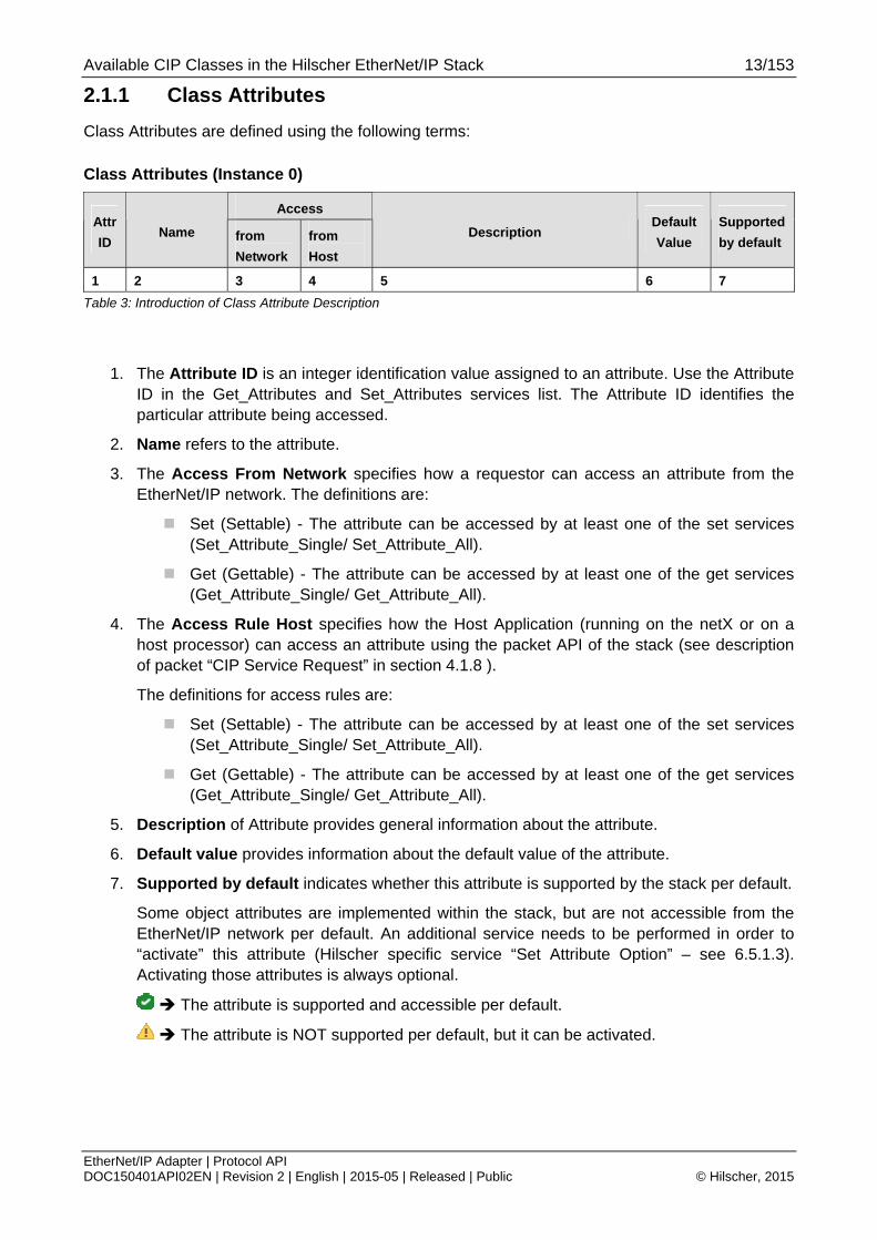
2.1.1 Class Attributes
Class Attributes are defined using the following terms:
Class Attributes (Instance 0)
Access Attr
ID Name from
Network
from
Host
Description Default
Value
Supported
by default
1 2 3 4 5 6 7
Table 3: Introduction of Class Attribute Description
1. The Attribute ID is an integer identification value assigned to an attribute. Use the Attribute ID in the Get_Attributes and Set_Attributes services list. The Attribute ID identifies the particular attribute being accessed.
2. Name refers to the attribute.
3. The Access From Network specifies how a requestor can access an attribute from the EtherNet/IP network. The definitions are:
Set (Settable) - The attribute can be accessed by at least one of the set services (Set_Attribute_Single/ Set_Attribute_All).
Get (Gettable) - The attribute can be accessed by at least one of the get services (Get_Attribute_Single/ Get_Attribute_All).
4. The Access Rule Host specifies how the Host Application (running on the netX or on a host processor) can access an attribute using the packet API of the stack (see description of packet “CIP Service Request” in section 4.1.8 ).
The definitions for access rules are:
Set (Settable) - The attribute can be accessed by at least one of the set services (Set_Attribute_Single/ Set_Attribute_All).
Get (Gettable) - The attribute can be accessed by at least one of the get services (Get_Attribute_Single/ Get_Attribute_All).
5. Description of Attribute provides general information about the attribute.
6. Default value provides information about the default value of the attribute.
7. Supported by default indicates whether this attribute is supported by the stack per default.
Some object attributes are implemented within the stack, but are not accessible from the EtherNet/IP network per default. An additional service needs to be performed in order to “activate” this attribute (Hilscher specific service “Set Attribute Option” – see 6.5.1.3). Activating those attributes is always optional.
The attribute is supported and accessible per default.
The attribute is NOT supported per default, but it can be activated.

Available CIP Classes in the Hilscher EtherNet/IP Stack 14/153
EtherNet/IP Adapter | Protocol API DOC150401API02EN | Revision 2 | English | 2015-05 | Released | Public © Hilscher, 2015
2.1.2 Instance Attributes
An Instance Attribute is an attribute that is unique to an object instance and not shared by the object class. Instance Attributes are defined in the same terms as Class Attributes.
Instance Attributes ( Instance 1-n)
Access Attr
ID Name from
Network
from
Host
Description Default
Value
Supported
by default
1 2 3 4 5 6 7
Table 4: Introduction of Instance Attribute Description
2.1.3 Services
Services can either address the class level (instance ID 0) or the instance level (instance ID 1-n) of a CIP object. Additionally, service can be sent by a device that is located inside the EtherNet/IP network or it can be sent by the host application of the stack.
Therefore, the services an object supports are described with two tables. The first table shows the common services that can be sent by both a device within the EtherNet/IP network or the host application of the stack. The second table shows the Hilscher specific services that can only be sent by the host application.
Both tables have the same format:
Addressing the object’s Service
Code
Name
Class
Level
Instance
Level
Description
1 2 3 4 5
Table 5: Introduction of Service Description
1. The Service Code is a hexadecimal value assigned to a specific CIP service. The service can either be defined within the EtherNet/IP specification or is a Hilscher specific service code (Hilscher specific services are described separately in chapter 6.5.1 “Hilscher specific CIP services”).
2. The Name refers to the service.
3. Addressing the object’s class level
The stack supports this service if it addresses the class level (instance 0).
The stack does not support this service for the class level.
4. Addressing the object’s instance level
The stack supports this service if it addresses the instance level (instance 1-n).
The stack does not support this service for the instance level.
5. The Description provides general information about the service.
Available CIP Classes in the Hilscher EtherNet/IP Stack 15/153
EtherNet/IP Adapter | Protocol API DOC150401API02EN | Revision 2 | English | 2015-05 | Released | Public © Hilscher, 2015
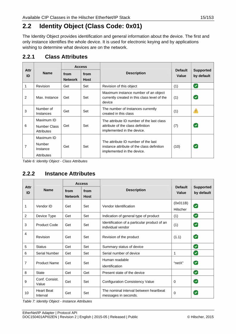
2.2 Identity Object (Class Code: 0x01)
The Identity Object provides identification and general information about the device. The first and only instance identifies the whole device. It is used for electronic keying and by applications wishing to determine what devices are on the network.
2.2.1 Class Attributes
Access Attr
ID Name from
Network
from
Host
Description Default
Value
Supported
by default
1 Revision Get Set Revision of this object (1)
2 Max. Instance Get Set Maximum instance number of an object currently created in this class level of the device
(1)
3 Number of Instances
Get Set The number of Instances currently created in this class
(1)
6
Maximum ID
Number Class Attributes
Get Set The attribute ID number of the last class attribute of the class definition implemented in the device.
(7)
7
Maximum ID
Number Instance
Attributes
Get Set The attribute ID number of the last instance attribute of the class definition implemented in the device.
(10)
Table 6: Identity Object - Class Attributes
2.2.2 Instance Attributes
Access Attr
ID Name from
Network
from
Host
Description Default
Value
Supported
by default
1 Vendor ID Get Set Vendor Identification (0x011B)
Hilscher
2 Device Type Get Set Indication of general type of product (1)
3 Product Code Get Set Identification of a particular product of an individual vendor
(1)
4
Revision Get Set Revision of the product (1.1)
5 Status Get Set Summary status of device
6 Serial Number Get Set Serial number of device 1
7 Product Name Get Set Human readable
identification “netX”
8 State Get Get Present state of the device
9 Conf. Consist. Value
Get Set Configuration Consistency Value 0
10 Heart Beat Interval
Get Set The nominal interval between heartbeat messages in seconds.
0
Table 7: Identity Object - Instance Attributes

Available CIP Classes in the Hilscher EtherNet/IP Stack 16/153
EtherNet/IP Adapter | Protocol API DOC150401API02EN | Revision 2 | English | 2015-05 | Released | Public © Hilscher, 2015
2.2.3 Supported Services
2.2.3.1 Common services coming from the EtherNet/IP network or host application
Addressing the object’s Service
Code
Name
Class
Level
Instance
Level
Description
0x01 Get Attribute All Returns content of instance or class attributes
0x05 Reset Reset the device
0x0E Get Attribute Single Returns value of attribute
0x10 Set Attribute Single Modifies value of attribute
Table 8: Identity Object - Common Services
2.2.3.2 Hilscher specific services coming from the host application
Addressing the object’s Service
Code
Name
Class
Level
Instance
Level
Description
0xFF32 Reset Object Reset object to default values
0xFF33 Get Attribute Option Returns options of an attribute
0xFF34 Set Attribute Option Modifies options of an attribute
Table 9: Identity Object - Hilscher Specific Services
Available CIP Classes in the Hilscher EtherNet/IP Stack 17/153
EtherNet/IP Adapter | Protocol API DOC150401API02EN | Revision 2 | English | 2015-05 | Released | Public © Hilscher, 2015
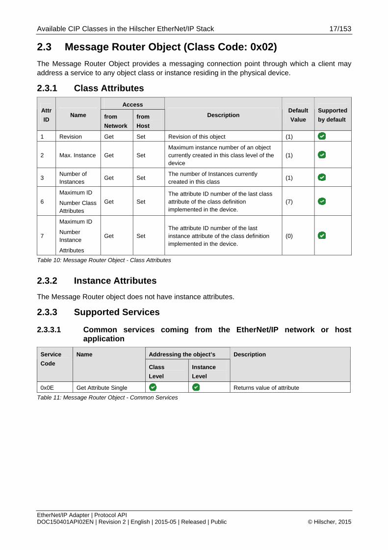
2.3 Message Router Object (Class Code: 0x02)
The Message Router Object provides a messaging connection point through which a client may address a service to any object class or instance residing in the physical device.
2.3.1 Class Attributes
Access Attr
ID Name from
Network
from
Host
Description Default
Value
Supported
by default
1 Revision Get Set Revision of this object (1)
2 Max. Instance Get Set Maximum instance number of an object currently created in this class level of the device
(1)
3 Number of Instances
Get Set The number of Instances currently created in this class
(1)
6
Maximum ID
Number Class Attributes
Get Set The attribute ID number of the last class attribute of the class definition implemented in the device.
(7)
7
Maximum ID
Number Instance
Attributes
Get Set The attribute ID number of the last instance attribute of the class definition implemented in the device.
(0)
Table 10: Message Router Object - Class Attributes
2.3.2 Instance Attributes
The Message Router object does not have instance attributes.
2.3.3 Supported Services
2.3.3.1 Common services coming from the EtherNet/IP network or host application
Addressing the object’s Service
Code
Name
Class
Level
Instance
Level
Description
0x0E Get Attribute Single Returns value of attribute
Table 11: Message Router Object - Common Services

Available CIP Classes in the Hilscher EtherNet/IP Stack 18/153
EtherNet/IP Adapter | Protocol API DOC150401API02EN | Revision 2 | English | 2015-05 | Released | Public © Hilscher, 2015
2.3.3.2 Hilscher specific services coming from the host application
Addressing the object’s Service
Code
Name
Class
Level
Instance
Level
Description
0xFF33 Get Attribute Option Returns options of an attribute
0xFF34 Set Attribute Option Modifies options of an attribute
Table 12: Message Router Object - Hilscher Specific Services

Available CIP Classes in the Hilscher EtherNet/IP Stack 19/153
EtherNet/IP Adapter | Protocol API DOC150401API02EN | Revision 2 | English | 2015-05 | Released | Public © Hilscher, 2015
2.4 Assembly Object (Class Code: 0x04)
The Assembly Object binds attributes of multiple objects, which allows data to or from each object to be sent or received over a single connection. Assembly Objects can be used to bind produced data or consumed data.
2.4.1 Class Attributes
Access Attr
ID Name from
Network
from
Host
Description Default
Value
Supported
by default
1 Revision Get Set Revision of this object (2)
2 Max. Instance Get Set Maximum instance number of an object currently created in this class level of the device
(0xFFFF)
3 Number of Instances
Get Set The number of Instances currently created in this class
(0)
6
Maximum ID
Number Class Attributes
Get Set The attribute ID number of the last class attribute of the class definition implemented in the device.
(7)
7
Maximum ID
Number Instance
Attributes
Get Set The attribute ID number of the last instance attribute of the class definition implemented in the device.
(7)
Table 13: Assembly Object - Class Attributes
2.4.2 Instance Attributes
Access Attr
ID Name from
Network
from
Host
Description Default
Value
Supported
by default
1 Number of Member
none Set Vendor Identification
2 Member None None Member list
3 Data Get Set
4
Size Get Set Number of bytes in Attribute 3
300 Member data list
None None Data of assembly members
301 Parameter None Get Assembly parameter
302 Status None Get Status of the assembly
Table 14: Assembly Object - Instance Attributes

Available CIP Classes in the Hilscher EtherNet/IP Stack 20/153
EtherNet/IP Adapter | Protocol API DOC150401API02EN | Revision 2 | English | 2015-05 | Released | Public © Hilscher, 2015
2.4.3 Supported Services
2.4.3.1 Common services coming from the EtherNet/IP network or host application
Addressing the object’s Service
Code
Name
Class
Level
Instance
Level
Description
0x0E Get Attribute Single Returns value of attribute
0x10 Set Attribute Single Modifies value of attribute
Table 15: Assembly Object - Common Services
2.4.3.2 Hilscher specific services coming from the host application
Addressing the object’s Service
Code
Name
Class
Level
Instance
Level
Description
0xFF33 Get Attribute Option Returns options of an attribute
0xFF34 Set Attribute Option Modifies options of an attribute
0x401 Assembly Create Creates an new assembly instance
0x402 Assembly Delete Deletes an assembly instance
0x403 Add Member Add an member to assembly
0x404 Del Member Remove member from Assembly
0xFF32 Reset Object Reset object to default values
0xFF33 Get Attribute Option Returns options of an attribute
0xFF34 Set Attribute Option Modifies options of an attribute
Table 16: Assembly Object - Hilscher Specific Services

Available CIP Classes in the Hilscher EtherNet/IP Stack 21/153
EtherNet/IP Adapter | Protocol API DOC150401API02EN | Revision 2 | English | 2015-05 | Released | Public © Hilscher, 2015
2.5 Connection Manager Object (Class Code: 0x06)
The Connection Manager Class allocates and manages the internal resources associated with both I/ O and Explicit Messaging Connections.
2.5.1 Class Attributes
Access Attr
ID Name from
Network
from
Host
Description Default
Value
Supported
by default
1 Revision Get Set Revision of this object (1)
2 Max. Instance Get Set Maximum instance number of an object currently created in this class level of the device
(1)
3 Number of Instances
Get Set The number of Instances currently created in this class
(1)
6
Maximum ID
Number Class Attributes
Get Set The attribute ID number of the last class attribute of the class definition implemented in the device.
(7)
7
Maximum ID
Number Instance
Attributes
Get Set The attribute ID number of the last instance attribute of the class definition implemented in the device.
(0)
Table 17: Connection Manager Object - Class Attributes
2.5.2 Instance Attributes
Access Attr
ID Name from
Network
from
Host
Description Default
Value
Supported
by default
1 Open Requests
Get Set Number of Forward Open service requests received.
(0)
Table 18: Connection Manager Object - Instance Attributes
2.5.3 Supported Services
2.5.3.1 Common services coming from the EtherNet/IP network or host application
Addressing the object’s Service
Code
Name
Class
Level
Instance
Level
Description
0x0E Get Attribute Single Returns value of attribute
0x10 Set Attribute Single Modifies value of attribute
0x54 Forward Open Open new connection
0x4E Forward Close Close connection
Table 19: Connection Manager Object - Common Services

Available CIP Classes in the Hilscher EtherNet/IP Stack 22/153
EtherNet/IP Adapter | Protocol API DOC150401API02EN | Revision 2 | English | 2015-05 | Released | Public © Hilscher, 2015
2.5.3.2 Hilscher specific services coming from the host application
Addressing the object’s Service
Code
Name
Class
Level
Instance
Level
Description
0xFF32 Reset Object Reset object to default values
0xFF33 Get Attribute Option Returns options of an attribute
0xFF34 Set Attribute Option Modifies options of an attribute
Table 20: Connection Manager Object - Hilscher Specific Services

Available CIP Classes in the Hilscher EtherNet/IP Stack 23/153
EtherNet/IP Adapter | Protocol API DOC150401API02EN | Revision 2 | English | 2015-05 | Released | Public © Hilscher, 2015
2.6 Time Sync Object (Class Code: 0x43)
The Time Sync Object (used for CIP SYNC) provides a CIP interface to the IEEE 1588 (IEC 61588) Standard for a Precision Clock Synchronization Protocol for Networked Measurement and Control Systems, commonly referred to as the Precision Time Protocol (PTP). When starting the stack, this object is not available right away. It needs to be activated using the packet EIP_OBJECT_MR_REGISTER_REQ (0x1A02).
For further information regarding CIP Sync and how it is used with the Hilscher EtherNet/IP stack have a look at the corresponding Application Note [7].
2.6.1 Class Attributes
Access Attr
ID Name from
Network
from
Host
Description Default
Value
Supported
by default
1 Revision Get Set Revision of this object (3)
2 Max. Instance Get Set Maximum instance number of an object currently created in this class level of the device
(1)
3 Number of Instances
Get Set The number of Instances currently created in this class
(1)
6
Maximum ID
Number Class Attributes
Get Set The attribute ID number of the last class attribute of the class definition implemented in the device.
(7)
7
Maximum ID
Number Instance
Attributes
Get Set The attribute ID number of the last instance attribute of the class definition implemented in the device.
(28)
Table 21: Time Sync Object - Class Attributes
2.6.2 Instance Attributes
Access Attr
ID Name from
Network
from
Host
Description Default
Value
Supported
by default
1 PTPEnable Set Set PTP Enable 0 (Disabled)
2 IsSynchronized
Get Get Local clock is synchronized with master 0
3 SystemTimeMicroseconds
Get Get Current value of system_time in microseconds
0
4 SystemTimeNanoseconds
Get Get Current value of system_time in nanoseconds
0
5 OffsetFromMaster
Get Get Offset between local clock and master clock
0
6 MaxOffsetFromMaster
Set Set Maximum offset between local clock and master clock
0
7 MeanPathDelayToMaster
Get Get Mean path delay to master 0

Available CIP Classes in the Hilscher EtherNet/IP Stack 24/153
EtherNet/IP Adapter | Protocol API DOC150401API02EN | Revision 2 | English | 2015-05 | Released | Public © Hilscher, 2015
Access Attr
ID Name from
Network
from
Host
Description Default
Value
Supported
by default
8 GrandMasterClockInfo
Get Get Grandmaster Clock Info all 0
9 ParentClockInfo
Get Get Parent Clock Info all 0
10 LocalClockIno Get Get Local Clock Info all 0
11 NumberOfPorts
Get Get Number of ports 1
12 PortStateInfo Get Get Port state info disabled
13 PortEnableCfg Set Set Port enable cfg enabled
14 PortLogAnnounceIntervalCfg
Set Set Port log announce interval cfg 0
15 PortLogSyncIntervalCfg
Set Set Port log sync interval cfg 0
16 Priority1 Priority 1
17 Priority2 Priority 2
18 DomainNumber
Set Set Domain number 0
19 ClockType Get Get Clock type 0
20 ManufactureIdentity
Get Get Manufacture identity all 0
21 ProductDescription
Get Get Product description “”
22 RevisionData Get Get Revision data “”
23 UserDescription
Get Get User description “”
24 PortProfileIdentityInfo
Get Get Port profile identity info 00-21-6C-00-01-00
25 PortPhysicalAddressInfo
Get Get Port physical address info all 0
26 PortProtocolAddressInfo
Get Get Port protocol address info all 0
27 StepsRemoved
Get Get Steps removed 0
28 SystemTimeAndOffset
Get Get System time and offset all 0
300 SyncParameters
Set Synchronization Parameters
Ta19ble 22: Time Sync Object - Instance Attributes

Available CIP Classes in the Hilscher EtherNet/IP Stack 25/153
EtherNet/IP Adapter | Protocol API DOC150401API02EN | Revision 2 | English | 2015-05 | Released | Public © Hilscher, 2015
2.6.3 Supported Services
2.6.3.1 Common services coming from the EtherNet/IP network or host application
Addressing the object’s Service
Code
Name
Class
Level
Instance
Level
Description
0x0E Get Attribute Single Returns value of attribute
0x10 Set Attribute Single Modifies value of attribute
Table 23: Time Sync Object - Common Services
2.6.3.2 Hilscher specific services coming from the host application
Addressing the object’s Service
Code
Name
Class
Level
Instance
Level
Description
0xFF32 Reset Object Reset object to default values
0xFF33 Get Attribute Option Returns options of an attribute
0xFF34 Set Attribute Option Modifies options of an attribute
Table 24: Time Sync Object - Hilscher Specific Services
2.6.4 Instance Attributes
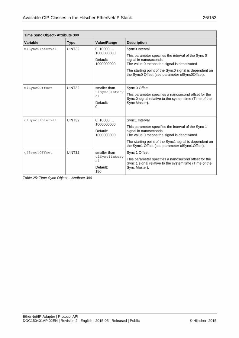
2.6.4.1 Attribute 300 - Sync Parameters
Attribute 300 of the Time Sync object is used to set some required synchronization-related parameters. These are used to adjust the interval and offset times for the hardware synchronization signals Sync 0 and Sync 1.
Basically, the Sync 0 signal is the interrupt that the host application will receive in order to retrieve the current system time. On each event the EtherNet/IP stack writes the current system time into the extended data area of the Dual Port Memory interface (for further information see CIP Sync Application Note [7]).
Note: Currently, only Sync 0 can be used.
Available CIP Classes in the Hilscher EtherNet/IP Stack 26/153
EtherNet/IP Adapter | Protocol API DOC150401API02EN | Revision 2 | English | 2015-05 | Released | Public © Hilscher, 2015
Time Sync Object- Attribute 300
Variable Type Value/Range Description
ulSync0Interval UINT32 0, 10000 … 1000000000
Default: 1000000000
Sync0 Interval
This parameter specifies the interval of the Sync 0 signal in nanoseconds. The value 0 means the signal is deactivated.
The starting point of the Sync0 signal is dependent on the Sync0 Offset (see parameter ulSync0Offset).
ulSync0Offset UINT32 smaller than ulSync0Interval
Default: 0
Sync 0 Offset
This parameter specifies a nanosecond offset for the Sync 0 signal relative to the system time (Time of the Sync Master).
ulSync1Interval UINT32 0, 10000 … 1000000000
Default: 1000000000
Sync1 Interval
This parameter specifies the interval of the Sync 1 signal in nanoseconds. The value 0 means the signal is deactivated.
The starting point of the Sync1 signal is dependent on the Sync1 Offset (see parameter ulSync1Offset).
ulSync1Offset UINT32 smaller than ulSync1Interval
Default: 150
Sync 1 Offset
This parameter specifies a nanosecond offset for the Sync 1 signal relative to the system time (Time of the Sync Master).
Table 25: Time Sync Object – Attribute 300

Available CIP Classes in the Hilscher EtherNet/IP Stack 27/153
EtherNet/IP Adapter | Protocol API DOC150401API02EN | Revision 2 | English | 2015-05 | Released | Public © Hilscher, 2015
2.7 Device Level Ring Object (Class Code: 0x47)
The Device Level Ring (DLR) Object provides the configuration of the DLR protocol. DLR is used for Ethernet Ring topology.
2.7.1 Class Attributes
Access Attr
ID Name from
Network
from
Host
Description Default Value Supported
by default
1 Revision Get Set Revision of this object (3)
2 Max. Instance Get Set Maximum instance number of an object currently created in this class level of the device
(1)
3 Number of Instances
Get Set The number of Instances currently created in this class
(1)
6
Maximum ID
Number Class Attributes
Get Set
The attribute ID number of the last class attribute of the class definition implemented in the device.
(7)
7
Maximum ID
Number Instance
Attributes
Get Set
The attribute ID number of the last instance attribute of the class definition implemented in the device.
(12)
Table 26: DLR Object - Class Attributes
2.7.2 Instance Attributes
Access Attr
ID Name from
Network
from
Host
Description Default Value Supported
by default
1 Network Topology
Get Get Current network topology 0 – Linear
2 Network Status
Get Get Current network status 0 – Normal
10 Active Supervisor
Get Get Active Supervisor Address (0)
12
Capability Flags
Get Get DLR capability of the device
0x82 (Beacon based Ring Node, Flush Table frame support)
Table 27: DLR Object - Instance Attributes

Available CIP Classes in the Hilscher EtherNet/IP Stack 28/153
EtherNet/IP Adapter | Protocol API DOC150401API02EN | Revision 2 | English | 2015-05 | Released | Public © Hilscher, 2015
2.7.3 Supported Services
2.7.3.1 Common services coming from the EtherNet/IP network or host application
Addressing the object’s Service
Code Name Class
Level
Instance
Level
Description
0x01 Get Attribute All Returns content of instance or class attributes
0x0E Get Attribute Single Returns value of attribute
Table 28: DLR Object - Common Services
2.7.3.2 Hilscher specific services coming from the host application
Addressing the object’s Service
Code Name Class
Level
Instance
Level
Description
0xFF32 Reset Object Reset object to default values
0xFF33 Get Attribute Option Returns options of an attribute
0xFF34 Set Attribute Option Modifies options of an attribute
Table 29: DLR Object - Hilscher Specific Service

Available CIP Classes in the Hilscher EtherNet/IP Stack 29/153
EtherNet/IP Adapter | Protocol API DOC150401API02EN | Revision 2 | English | 2015-05 | Released | Public © Hilscher, 2015
2.8 Quality of Service Object (Class Code: 0x48)
The Quality of Service (QoS) Object provides the configuration of frame priorities. Ethernet frame priorities are set at the Differentiate Service Code Points (DSCP) or at the 802.1Q Tag.
2.8.1 Class Attributes
Access Attr
ID Name from
Network
from
Host
Description Default Value Supported
by default
1 Revision Get Set Revision of this object (3)
2 Max. Instance Get Set Maximum instance number of an object currently created in this class level of the device
(1)
3 Number of Instances
Get Set The number of Instances currently created in this class
(1)
6
Maximum ID
Number Class Attributes
Get Set
The attribute ID number of the last class attribute of the class definition implemented in the device.
(7)
7
Maximum ID
Number Instance
Attributes
Get Set
The attribute ID number of the last instance attribute of the class definition implemented in the device.
(12)
Table 30: QoS Object - Class Attributes
2.8.2 Instance Attributes
Access Attr
ID Name from
Network
from
Host
Description Default Value Supported
by default
1 802.1Q Tag Enable
Set Set Current network topology 0 - disabled
2 DSCP PTP Event
Set Set DSCP value for PTP Event frames
(59)
3 DSCP PTP General
Set Set DSCP value for PTP general frames
(47)
4
DSCP Urgent Set Set
DSCP value for implicit messages with urgent priority
(55)
5 DSCP Scheduled
Set Set DSCP value for implicit messages with scheduled priority
(47)
6 DSCP High Set Set DSCP value for implicit messages with high priority
(43)
7 DSCP Low Set Set DSCP value for implicit messages with low priority
(31)
8 DSCP Explicit Set Set DSCP value for explicit messages
(27)
Table 31: QoS Object - Instance Attributes

Available CIP Classes in the Hilscher EtherNet/IP Stack 30/153
EtherNet/IP Adapter | Protocol API DOC150401API02EN | Revision 2 | English | 2015-05 | Released | Public © Hilscher, 2015
2.8.3 Supported Services
2.8.3.1 Common services coming from the EtherNet/IP network or host application
Addressing the object’s Service
Code Name Class
Level
Instance
Level
Description
0x0E Get Attribute Single Returns value of attribute
0x10 Set Attribute Single Modifies value of attribute
Table 32: Quality of Service Object - Common Services
2.8.3.2 Hilscher specific services coming from the host application
Addressing the object’s Service
Code Name Class
Level
Instance
Level
Description
0xFF33 Get Attribute Option Returns options of an attribute
0xFF34 Set Attribute Option Modifies options of an attribute
Table 33: Quality of Service Object - Hilscher Specific Service

Available CIP Classes in the Hilscher EtherNet/IP Stack 31/153
EtherNet/IP Adapter | Protocol API DOC150401API02EN | Revision 2 | English | 2015-05 | Released | Public © Hilscher, 2015
2.9 TCP/IP Interface Object (Class Code: 0xF5)
The TCP/IP Interface Object provides the mechanism to configure a device’s TCP/IP network interface. Examples of configurable items include the device’s IP Address, Network Mask, and Gateway Address.
The EtherNet/IP Adapter stack supports exactly one instance of the TCP/IP Interface Object.
2.9.1 Class Attributes
Access Attr
ID Name from
Network
from
Host
Description Default Value Supported
by default
1 Revision Get Set Revision of this object (4)
2 Max. Instance Get Set Maximum instance number of an object currently created in this class level of the device
(1)
3 Number of Instances
Get Set The number of Instances currently created in this class
(1)
6
Maximum ID
Number Class Attributes
Get Set
The attribute ID number of the last class attribute of the class definition implemented in the device.
(7)
7
Maximum ID
Number Instance
Attributes
Get Set
The attribute ID number of the last instance attribute of the class definition implemented in the device.
(13)
Table 34: TCP/IP Interface Object - Class Attributes
2.9.2 Instance Attributes
Access Attr
ID Name from
Network
from
Host
Description Default Value Supported
by default
1 Status Get Set Interface status
2 Configuration
Capability Get Set Interface capability flags (0x95)
3 Configuration
Control Set Set Interface control flags (0)
4
Physical Link
Object Get Get Path to physical link object
(0x20 0xF6 0x24 0x01)
5 Interface
Configuration Set Set (0)
6 Host Name Set Set
The Host Name attribute contains the device’s host name, which can be used for informational purposes.
(“”)
7 Safety Network Number
Get Set See CIP Safety Specification,
Volume 5, Chapter 3 (0)

Available CIP Classes in the Hilscher EtherNet/IP Stack 32/153
EtherNet/IP Adapter | Protocol API DOC150401API02EN | Revision 2 | English | 2015-05 | Released | Public © Hilscher, 2015
Access Attr
ID Name from
Network
from
Host
Description Default Value Supported
by default
8 TTL Value Set Set TTL value for EtherNet/IP multicast packets
(1)
9 Mcast Config Set Set IP multicast address
configuration (0)
10 SelectAcd Set Set Activates the use of ACD (1)
11 LastConflictDetected
Set Set Structure containing information related to the last conflict detected
(0)
12
EtherNet/IP
Quick Connect
Set Set Enable/Disable of Quick Connect feature
(0)
13 Encapsulation Inactivity Timeout
Set Set Number of seconds till TCP connection is closed on encapsulation inactivity
(120)
Table 35: TCP/IP Interface Object - Instance Attributes
2.9.3 Supported Services
2.9.3.1 Common services coming from the EtherNet/IP network or host application
Addressing the object’s Service
Code
Name
Class
Level
Instance
Level
Description
0x01 Get Attribute All
Returns content of instance or class attributes
0x0E Get Attribute Single Returns value of attribute
0x10 Set Attribute Single Modifies value of attribute
Table 36: TCP/IP Interface Object - Common Services
2.9.3.2 Hilscher specific services coming from the host application
Addressing the object’s Service
Code Name Class
Level
Instance
Level
Description
0xF501 Get Multicast Get next multicast address
0xFF32 Reset Object Reset object to default values
0xFF33 Get Attribute Option Returns options of an attribute
0xFF34 Set Attribute Option Modifies options of an attribute
Table 37: TCP/IP Interface Object - Hilscher Specific Services

Available CIP Classes in the Hilscher EtherNet/IP Stack 33/153
EtherNet/IP Adapter | Protocol API DOC150401API02EN | Revision 2 | English | 2015-05 | Released | Public © Hilscher, 2015
2.10 Ethernet Link Object (Class Code: 0xF6)
The Ethernet Link Object maintains link-specific status information for the Ethernet communications interface. If the device is a multi-port device, it holds more than one instance of this object. Usually, when using the 2-port switch, instance 1 is assigned to Ethernet port 0 and instance 2 is assigned to Ethernet port 1.
2.10.1 Class Attributes
Access Attr
ID Name from
Network
from
Host
Description Default
Value
Supported
by default
1 Revision Get Set Revision of this object (3)
2 Max. Instance Get Set Maximum instance number of an object currently created in this class level of the device
(2)
3 Number of Instances
Get Set The number of Instances currently created in this class
(2)
6
Maximum ID
Number Class Attributes
Get Set The attribute ID number of the last class attribute of the class definition implemented in the device.
(7)
7
Maximum ID
Number Instance
Attributes
Get Set The attribute ID number of the last instance attribute of the class definition implemented in the device.
(10)
Table 38: Ethernet Link Object - Class Attributes
2.10.2 Instance Attributes
Access Attr
ID Name from
Network
from
Host
Description Default
Value
Supported
by default
1 Interface Speed
Get Get Interface speed currently
in use (100)
2 Interface Flags
Get Get Interface status flags (0x20)
3 Physical Address
Get Set MAC layer address
4
Interface Counters
Get Set
5 Media Counters
Get Set Media specific counters
6 Interface Control
Set Set Configuration for physical interface (0)
7 Interface Type Get Set Type of interface: twisted pair, fiber (0x02)
8 Interface State
Get Set Current state of interface (0)

Available CIP Classes in the Hilscher EtherNet/IP Stack 34/153
EtherNet/IP Adapter | Protocol API DOC150401API02EN | Revision 2 | English | 2015-05 | Released | Public © Hilscher, 2015
Access Attr
ID Name from
Network
from
Host
Description Default
Value
Supported
by default
9 Admin State Set Set Administrative state:
enable, disable (enable)
10 Interface Label
Get Set Human readable identification (“port1”,”port2”)
300 MDIX Set Set MDIX configuration
MDI, MDIX, autoMDI
(autoMDI)
Table 39: Ethernet Link Object - Instance Attributes
2.10.3 Supported Services
2.10.3.1 Common services coming from the EtherNet/IP network or host application
Addressing the object’s Service
Code
Name
Class
Level
Instance
Level
Description
0x01 Get Attribute All
Returns content of instance or class attributes
0x0E Get Attribute Single Returns value of attribute
0x10 Set Attribute Single Modifies value of attribute
Table 40: Ethernet Link Object - Common Services
2.10.3.2 Hilscher specific services coming from the host application
Addressing the object’s Service
Code Name Class
Level
Instance
Level
Description
0xFF33 Get Attribute Option Returns options of an attribute
0xFF34 Set Attribute Option Modifies options of an attribute
Table 41: Ethernet Link Object - Hilscher Specific Services

Available CIP Classes in the Hilscher EtherNet/IP Stack 35/153
EtherNet/IP Adapter | Protocol API DOC150401API02EN | Revision 2 | English | 2015-05 | Released | Public © Hilscher, 2015
2.11 Predefined Connection Object (Class Code: 0x401)
The Predefined Connection Object maintains the possible implicit connections.
This is a Hilscher specific CIP object.
2.11.1 Class Attributes
Access Attr
ID Name from
Network
from
Host
Description Default
Value
Supported
by default
1 Revision Get Set Revision of this object (1)
2 Max. Instance Get Set Maximum instance number of an object currently created in this class level of the device
()
3 Number of Instances
Get Set The number of Instances currently created in this class
()
6
Maximum ID
Number Class Attributes
Get Set The attribute ID number of the last class attribute of the class definition implemented in the device.
(7)
7
Maximum ID
Number Instance
Attributes
Get Set The attribute ID number of the last instance attribute of the class definition implemented in the device.
()
Table 42: Predefined Connection Object - Class Attributes
2.11.2 Instance Attributes
Access Attr
ID Name from
Network
from
Host
Description Default
Value
Supported
by default
1 State Get Get State of the connection
2 Count Get Get Number of connections
3 Configuration Get Get Connection configuration
Table 43: Predefined Connection Object - Instance Attributes
2.11.3 Supported Services
2.11.3.1 Common services coming from the EtherNet/IP network or host application
Addressing the object’s Service
Code
Name
Class
Level
Instance
Level
Description
0x08 Create Create new predefined connection instance
0x09 Delete Delete predefined connection instance
0x0E Get Attribute Single Returns value of attribute

Available CIP Classes in the Hilscher EtherNet/IP Stack 36/153
EtherNet/IP Adapter | Protocol API DOC150401API02EN | Revision 2 | English | 2015-05 | Released | Public © Hilscher, 2015
Addressing the object’s Service
Code
Name
Class
Level
Instance
Level
Description
0x10 Set Attribute Single Modifies value of attribute
Table 44: Predefined Connection Object - Common Services
2.11.3.2 Hilscher specific services coming from the host application
Addressing the object’s Service
Code Name Class
Level
Instance
Level
Description
0xFF01 x Open Connection Checks if connection is allowed and reserves requested resources
0xFF02 x Close Connection Free resources needed for the connection
0xFF32 Reset Object Reset object to default values
0xFF33 Get Attribute Option Returns options of an attribute
0xFF34 Set Attribute Option Modifies options of an attribute
Table 45: Predefined Connection Object - Hilscher Specific Services

Available CIP Classes in the Hilscher EtherNet/IP Stack 37/153
EtherNet/IP Adapter | Protocol API DOC150401API02EN | Revision 2 | English | 2015-05 | Released | Public © Hilscher, 2015
2.12 IO Mapping Object (Class Code: 0x402)
The IO Mapping Object maintains the assignment of process data. It is used to map the I/O area of dual port memory to specific assemblies.
This is a Hilscher specific CIP object.
2.12.1 Class Attributes
Access Attr
ID Name from
Network
from
Host
Description Default
Value
Supported
by default
1 Revision Get Set Revision of this object (1)
2 Max. Instance Get Set Maximum instance number of an object currently created in this class level of the device
()
3 Number of Instances
Get Set The number of Instances currently created in this class
()
6
Maximum ID
Number Class Attributes
Get Set The attribute ID number of the last class attribute of the class definition implemented in the device.
(7)
7
Maximum ID
Number Instance
Attributes
Get Set The attribute ID number of the last instance attribute of the class definition implemented in the device.
(3)
Table 46: IO Mapping Object - Class Attributes
2.12.2 Instance Attributes
Access Attr
ID Name from
Network
from
Host
Description Default
Value
Supported
by default
1 Status Get Get Status of I/O data
2 Length Get Get Length of I/O data
3 Data Get Get I/O data
Table 47: IO Mapping Object - Instance Attributes
2.12.3 Supported Services
2.12.3.1 Common services coming from the EtherNet/IP network or host application
Addressing the object’s Service
Code
Name
Class
Level
Instance
Level
Description
0x0E Get Attribute Single Returns value of attribute
0x10 Set Attribute Single Modifies value of attribute
Table 48: IO Mapping Object - Common Services

Available CIP Classes in the Hilscher EtherNet/IP Stack 38/153
EtherNet/IP Adapter | Protocol API DOC150401API02EN | Revision 2 | English | 2015-05 | Released | Public © Hilscher, 2015
2.12.3.2 Hilscher specific services coming from the host application
Addressing the object’s Service
Code Name Class
Level
Instance
Level
Description
0xFF01 Create Member Creates a new I/O Mapping entry
0xFF02 Delete Member Deletes I/O Mapping entry
0xFF32 Reset Object Reset object to default values
0xFF33 Get Attribute Option Returns options of an attribute
0xFF34 Set Attribute Option Modifies options of an attribute
Table 49: IO Mapping Object - Hilscher Specific Services
Getting Started/ Configuration 39/153
EtherNet/IP Adapter | Protocol API DOC150401API02EN | Revision 2 | English | 2015-05 | Released | Public © Hilscher, 2015
3 Getting Started/ Configuration
3.1 Configuration Procedures
The following ways are available to configure the EtherNet/IP Adapter:
Using the Configuration Tool SYCON.net
By netX configuration and diagnostic utility
By configuration packets
3.1.1 Using the Configuration Tool SYCON.net
The easiest way to configure the EtherNet/IP Adapter is using Hilscher’s configuration tool SYCON.net. This tool is described in a separate documentation.
3.1.2 Using the netX configuration and diagnostic utility
The configuration of the EtherNet/IP Adapter using Hilscher’s netX configuration and diagnostic utility, is described in a separate documentation.
3.1.3 Using the Packet API of the EtherNet/IP Protocol Stack
Depending of the interface the host application has to the EtherNet/IP stack, there are different possibilities of how configuration can be performed.
For more information how to accomplish this, please see section 3.2
3.2 Configuration Using the Packet API
In section 2 “Available CIP Classes in the Hilscher EtherNet/IP Stack” the default Hilscher CIP Object Model is displayed. This section explains how these objects can be configured using the Packet API of the EtherNet/IP stack.
There are some configuration sets available to configure the device. The Configuration Set must be chosen depending on the requirements for the device you want to develop and on the CIP Object Model you want the device to have.
Table 50: Configuration Sets shows the available sets and describes the general functionalities that come with the corresponding set.

Getting Started/ Configuration 40/153
EtherNet/IP Adapter | Protocol API DOC150401API02EN | Revision 2 | English | 2015-05 | Released | Public © Hilscher, 2015
Scenario Name of
Configuration Set
Description
Basic
This set provides a basic functionality
Cyclic communication/ implicit messaging (Transport class1 and Class0). Two assembly instances are available, one for input and one for output data.
Acyclic access (explicit messaging) to all predefined Hilscher CIP objects (unconnected/connected).
Support of Device Level Ring (DLR) protocol.
Support of ACD (Address Conflict Detection)
Support of Quick Connect
Storage of changed Attributes
Using this configuration the device’s CIP object model will look like the one that is illustrated in Figure 1.
Note: If your application/device needs a special functionality that is not covered by the basic Packet Set, please use the Extended Packet Set described below.
Loadable Firmware
Extended
Using this Configuration Set, the host application is free to design the device’s CIP object model in all aspects. In addition to the functionalities that come with the Basic Configuration Set, this set provides the following:
Up to 32 assembly instances possible.
Additional configuration assembly possible (necessary if the device needs configuration parameters from the Scanner/Master/PLC before going into cyclic communication).
Use additional CIP objects (that might be necessary when using a special CIP Profile). These objects are also accessible via acyclic/explicit messages.
This Configuration Set can, of course, also be used if only a basic configuration is desired.
Note: All changes of any non volatile object attribute has to be handled from the host application.
Table 50: Configuration Sets

Getting Started/ Configuration 41/153
EtherNet/IP Adapter | Protocol API DOC150401API02EN | Revision 2 | English | 2015-05 | Released | Public © Hilscher, 2015
3.2.1 Basic Configuration Set
3.2.1.1 Configuration Packets
To configure the EtherNet/IP Stack’s default CIP objects the following packets are necessary:
No. of section Packet Name Command
Code
(REQ/CNF)
Page
4.1.1 Configure the Device with Configuration Parameter 0x3612/ 0x3613
89
RCX_REGISTER_APP_REQ – Register the Application at the stack in order to receive indications
(see [1] “DPM Manual” for more information)
0x2F10/ 0x2F11
RCX_CHANNEL_INIT_REQ – Perform channel initialization
(see [1] “DPM Manual” for more information)
0x2F80/ 0x2F81
Table 51: Basic Configuration Set - Configuration Packets
3.2.1.2 Optional Request Packets
In addition to the request packets related to configuration, there are some more request packets the application can use. It is recommended to use Application controlled start at ulSystemFlags of the EIP_APS_SET_CONFIGURATION_PARAMETERS_REQ when optional packets are used for configuration
No. of section Packet Name Command
code
(REQ/CNF)
Page
4.1.2 Set Parameter Flags 0x360A/ 0x360B
59
4.3.1 Get Module Status/ Network Status 0x360E/ 0x360F
123
4.1.4 Register an additional Object Class at the Message Router 0x1A02/ 0x1A03
64
4.1.5 Register a new Assembly Instance 0x1A0C/ 0x1A0D
67
4.1.7 Register Service 0x1A44/ 0x1A45
78
4.1.8 CIP Service Request 0x1AF8/ 0x1AF9
81
Table 52: Additional Request Packets Using the Basic Configuration Set
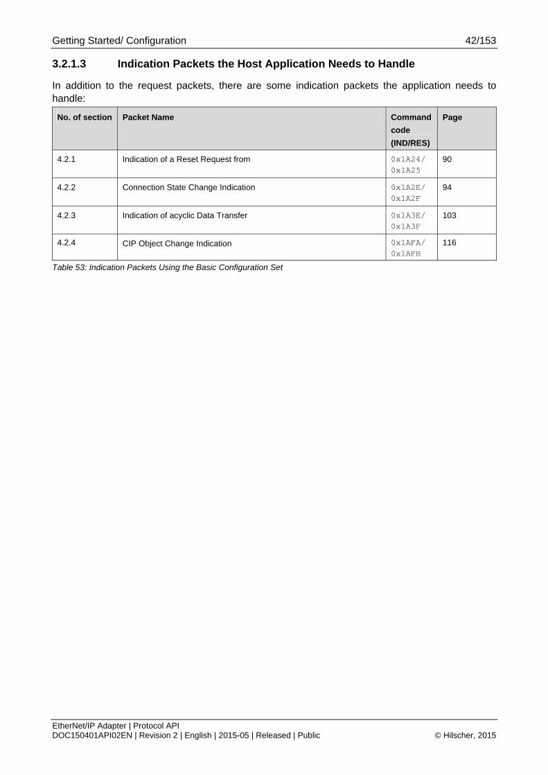
Getting Started/ Configuration 42/153
EtherNet/IP Adapter | Protocol API DOC150401API02EN | Revision 2 | English | 2015-05 | Released | Public © Hilscher, 2015
3.2.1.3 Indication Packets the Host Application Needs to Handle
In addition to the request packets, there are some indication packets the application needs to handle:
No. of section Packet Name Command
code
(IND/RES)
Page
4.2.1 Indication of a Reset Request from 0x1A24/ 0x1A25
90
4.2.2 Connection State Change Indication 0x1A2E/ 0x1A2F
94
4.2.3 Indication of acyclic Data Transfer 0x1A3E/ 0x1A3F
103
4.2.4 CIP Object Change Indication 0x1AFA/ 0x1AFB
116
Table 53: Indication Packets Using the Basic Configuration Set

Getting Started/ Configuration 43/153
EtherNet/IP Adapter | Protocol API DOC150401API02EN | Revision 2 | English | 2015-05 | Released | Public © Hilscher, 2015
3.2.1.4 Configuration Sequence
The packets of Packet Set “Basic” should be sent in the order that is illustrated in Figure 2.
Figure 2: Configuration Sequence Using the Basic Configuration Set

Getting Started/ Configuration 44/153
EtherNet/IP Adapter | Protocol API DOC150401API02EN | Revision 2 | English | 2015-05 | Released | Public © Hilscher, 2015
3.2.2 Extended Configuration Set
3.2.2.1 Configuration Packets
To configure the EtherNet/IP Stack, the following packets are necessary:
No. of section Packet Name Command
Code
(REQ/CNF)
Page
4.1.8 CIP Service Request 81
4.1.3 Finish configuration of CIP Objects 62
RCX_REGISTER_APP_REQ – Register the Application at the stack in order to receive indications
(see [1] “DPM Manual” for more information)
0x2F10/ 0x2F11
Table 54: Extended Configuration Set - Configuration Packets
3.2.2.2 Optional Request Packets
In addition to the request packets related to configuration, there are some more request packets the application can use:
No. of section Packet Name Command
code
(REQ/CNF)
Page
4.1.2 Set Parameter Flags 0x360A/ 0x360B
59
4.3.1 Get Module Status/ Network Status 0x360E/ 0x360F
123
4.1.4 Register an additional Object Class at the Message Router 0x1A02/ 0x1A03
64
4.1.5 Register a new Assembly Instance 0x1A0C/ 0x1A0D
67
4.1.6 Set the Device’s Identity Information 0x1A16/ 0x1A17
73
4.1.7 Register Service 0x1A44/ 0x1A45
78
Table 55: Additional Request Packets Using the Basic Configuration Set

Getting Started/ Configuration 45/153
EtherNet/IP Adapter | Protocol API DOC150401API02EN | Revision 2 | English | 2015-05 | Released | Public © Hilscher, 2015
3.2.2.3 Indication Packets the Host Application Needs to Handle
In addition to the request packets, there are some indication packets the application needs to handle:
No. of section Packet Name Command
code
(IND/RES)
Page
4.2.1 Indication of a Reset Request from 0x1A24/ 0x1A25
90
4.2.2 Connection State Change Indication 0x1A2E/ 0x1A2F
94
4.2.3 Indication of acyclic Data Transfer 0x1A3E/ 0x1A3F
103
4.2.4 CIP Object Change Indication 0x1AFA/ 0x1AFB
116
Table 56: Indication Packets Using the Extended Packet Set
3.2.2.4 Configuration Sequence
At the Extended Configuration Set all values are set inside the CIP object dictionary. This shall be done with the EIP_OBJECT_CIP_SERVICE_REQ (4.1.8).
The following Figure 3 illustrates an example packet sequence using the Extended Packet Set. Using the shown sequence and packets will basically give you a configuration that is equal to the configuration you get when using the Basic Packet Set. Of course, you can use additional packets to further extend your Device’s object model or activate additional functionalities.

Getting Started/ Configuration 46/153
EtherNet/IP Adapter | Protocol API DOC150401API02EN | Revision 2 | English | 2015-05 | Released | Public © Hilscher, 2015
Figure 3: Configuration Sequence Using the Extended Packet Set
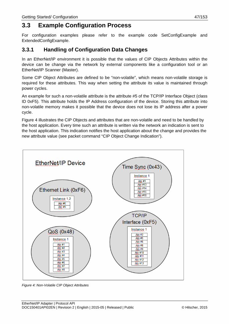
Getting Started/ Configuration 47/153
EtherNet/IP Adapter | Protocol API DOC150401API02EN | Revision 2 | English | 2015-05 | Released | Public © Hilscher, 2015
3.3 Example Configuration Process
For configuration examples please refer to the example code SetConfigExample and ExtendedConfigExample.
3.3.1 Handling of Configuration Data Changes
In an EtherNet/IP environment it is possible that the values of CIP Objects Attributes within the device can be change via the network by external components like a configuration tool or an EtherNet/IP Scanner (Master).
Some CIP Object Attributes are defined to be “non-volatile”, which means non-volatile storage is required for these attributes. This way when setting the attribute its value is maintained through power cycles.
An example for such a non-volatile attribute is the attribute #5 of the TCP/IP Interface Object (class ID 0xF5). This attribute holds the IP Address configuration of the device. Storing this attribute into non-volatile memory makes it possible that the device does not lose its IP address after a power cycle.
Figure 4 illustrates the CIP Objects and attributes that are non-volatile and need to be handled by the host application. Every time such an attribute is written via the network an indication is sent to the host application. This indication notifies the host application about the change and provides the new attribute value (see packet command “CIP Object Change Indication”).
Figure 4: Non-Volatile CIP Object Attributes
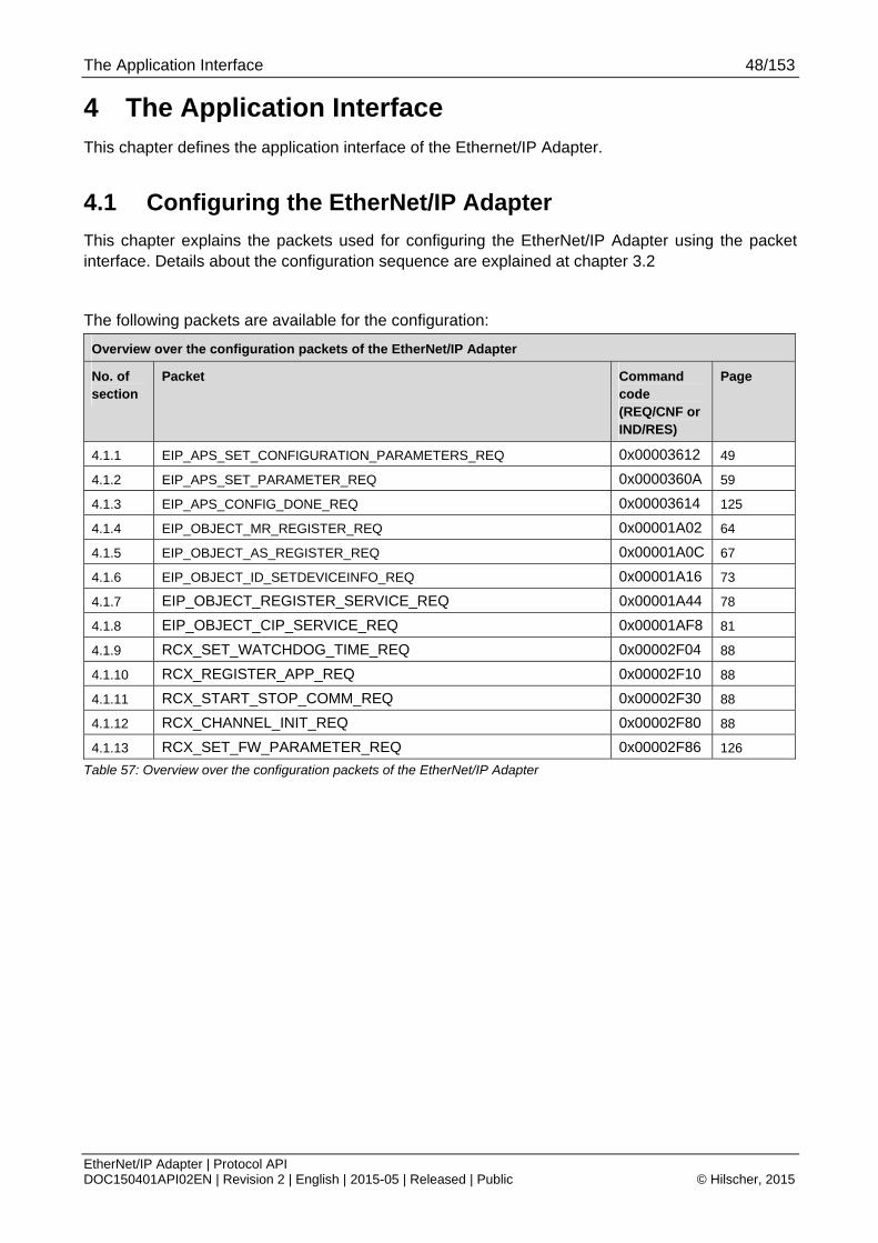
The Application Interface 48/153
EtherNet/IP Adapter | Protocol API DOC150401API02EN | Revision 2 | English | 2015-05 | Released | Public © Hilscher, 2015
4 The Application Interface This chapter defines the application interface of the Ethernet/IP Adapter.
4.1 Configuring the EtherNet/IP Adapter
This chapter explains the packets used for configuring the EtherNet/IP Adapter using the packet interface. Details about the configuration sequence are explained at chapter 3.2
The following packets are available for the configuration:
Overview over the configuration packets of the EtherNet/IP Adapter
No. of section
Packet Command code (REQ/CNF or IND/RES)
Page
4.1.1 EIP_APS_SET_CONFIGURATION_PARAMETERS_REQ 0x00003612 49
4.1.2 EIP_APS_SET_PARAMETER_REQ 0x0000360A 59
4.1.3 EIP_APS_CONFIG_DONE_REQ 0x00003614 125
4.1.4 EIP_OBJECT_MR_REGISTER_REQ 0x00001A02 64
4.1.5 EIP_OBJECT_AS_REGISTER_REQ 0x00001A0C 67
4.1.6 EIP_OBJECT_ID_SETDEVICEINFO_REQ 0x00001A16 73
4.1.7 EIP_OBJECT_REGISTER_SERVICE_REQ 0x00001A44 78
4.1.8 EIP_OBJECT_CIP_SERVICE_REQ 0x00001AF8 81
4.1.9 RCX_SET_WATCHDOG_TIME_REQ 0x00002F04 88
4.1.10 RCX_REGISTER_APP_REQ 0x00002F10 88
4.1.11 RCX_START_STOP_COMM_REQ 0x00002F30 88
4.1.12 RCX_CHANNEL_INIT_REQ 0x00002F80 88
4.1.13 RCX_SET_FW_PARAMETER_REQ 0x00002F86 126
Table 57: Overview over the configuration packets of the EtherNet/IP Adapter

The Application Interface 49/153
EtherNet/IP Adapter | Protocol API DOC150401API02EN | Revision 2 | English | 2015-05 | Released | Public © Hilscher, 2015
4.1.1 Configure the Device with Configuration Parameter
Note: This packet replaces the packet EIP_APS_SET_CONFIGURATION_REQ(cmd:0x3608). For compatibility reasons this packet is still supported. However, for new developments only the packet EIP_APS_SET_CONFIGURATION_PARAMETERS_REQ (cmd: 0x3612) shall be used.
This service can be used by the host application in order to configure the device with configuration parameters. This packet is part of the basic packet set and provides a basic configuration to all default CIP objects within the stack.
Using this configuration method the stack automatically creates two assembly instances that can be used implicit/cyclic communication. The I/O data of theses instances will start at offset 0 at the dual port memory (relative offset to the input and output areas of the DPM).
Note: If you set usVendId, usProductType and usProductCode to zero, Hilscher’s firmware standard values will be applied for the according variables.
The following rules apply for the behavior of the EtherNet/IP Adapter Stack when receiving a set configuration command:
The configuration data is checked for consistency and integrity.
In case of failure no data is accepted.
In case of success the configuration parameters are stored internally (within the RAM).
The parameterized data will be activated only after a channel init (RCX_CHANNEL_INIT_REQ).
This packet does not perform any registration at the stack automatically. Registering must be performed with a separate packet such as the registration packet described in the netX Dual-Port-Memory Manual (RCX_REGISTER_APP_REQ, code 0x2F10).
This request will be denied if the “configuration locked” flag is set in the DPM.
Figure 5: Sequence Diagram for the EIP_APS_SET_CONFIGURATION_PARAMETERS_REQ/CNF Packet
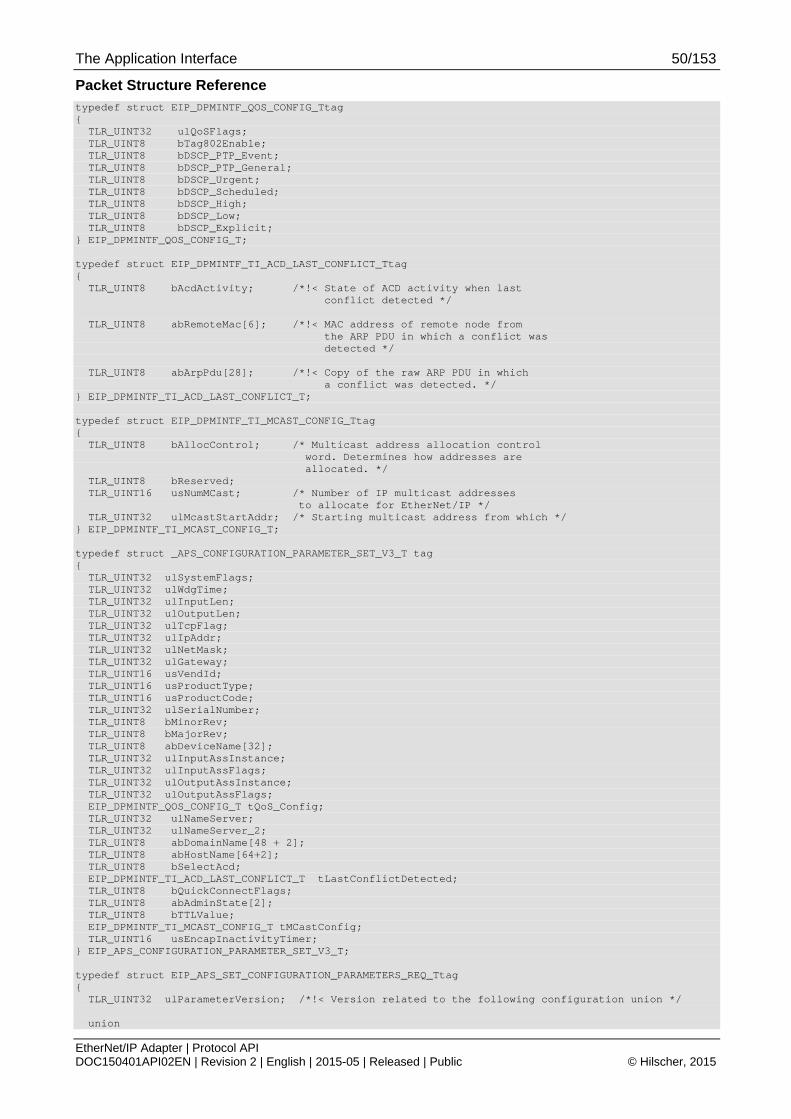
The Application Interface 50/153
EtherNet/IP Adapter | Protocol API DOC150401API02EN | Revision 2 | English | 2015-05 | Released | Public © Hilscher, 2015
Packet Structure Reference typedef struct EIP_DPMINTF_QOS_CONFIG_Ttag { TLR_UINT32 ulQoSFlags; TLR_UINT8 bTag802Enable; TLR_UINT8 bDSCP_PTP_Event; TLR_UINT8 bDSCP_PTP_General; TLR_UINT8 bDSCP_Urgent; TLR_UINT8 bDSCP_Scheduled; TLR_UINT8 bDSCP_High; TLR_UINT8 bDSCP_Low; TLR_UINT8 bDSCP_Explicit; } EIP_DPMINTF_QOS_CONFIG_T; typedef struct EIP_DPMINTF_TI_ACD_LAST_CONFLICT_Ttag { TLR_UINT8 bAcdActivity; /*!< State of ACD activity when last conflict detected */ TLR_UINT8 abRemoteMac[6]; /*!< MAC address of remote node from the ARP PDU in which a conflict was detected */ TLR_UINT8 abArpPdu[28]; /*!< Copy of the raw ARP PDU in which a conflict was detected. */ } EIP_DPMINTF_TI_ACD_LAST_CONFLICT_T; typedef struct EIP_DPMINTF_TI_MCAST_CONFIG_Ttag { TLR_UINT8 bAllocControl; /* Multicast address allocation control word. Determines how addresses are allocated. */ TLR_UINT8 bReserved; TLR_UINT16 usNumMCast; /* Number of IP multicast addresses to allocate for EtherNet/IP */ TLR_UINT32 ulMcastStartAddr; /* Starting multicast address from which */ } EIP_DPMINTF_TI_MCAST_CONFIG_T; typedef struct _APS_CONFIGURATION_PARAMETER_SET_V3_T tag { TLR_UINT32 ulSystemFlags; TLR_UINT32 ulWdgTime; TLR_UINT32 ulInputLen; TLR_UINT32 ulOutputLen; TLR_UINT32 ulTcpFlag; TLR_UINT32 ulIpAddr; TLR_UINT32 ulNetMask; TLR_UINT32 ulGateway; TLR_UINT16 usVendId; TLR_UINT16 usProductType; TLR_UINT16 usProductCode; TLR_UINT32 ulSerialNumber; TLR_UINT8 bMinorRev; TLR_UINT8 bMajorRev; TLR_UINT8 abDeviceName[32]; TLR_UINT32 ulInputAssInstance; TLR_UINT32 ulInputAssFlags; TLR_UINT32 ulOutputAssInstance; TLR_UINT32 ulOutputAssFlags; EIP_DPMINTF_QOS_CONFIG_T tQoS_Config; TLR_UINT32 ulNameServer; TLR_UINT32 ulNameServer_2; TLR_UINT8 abDomainName[48 + 2]; TLR_UINT8 abHostName[64+2]; TLR_UINT8 bSelectAcd; EIP_DPMINTF_TI_ACD_LAST_CONFLICT_T tLastConflictDetected; TLR_UINT8 bQuickConnectFlags; TLR_UINT8 abAdminState[2]; TLR_UINT8 bTTLValue; EIP_DPMINTF_TI_MCAST_CONFIG_T tMCastConfig; TLR_UINT16 usEncapInactivityTimer; } EIP_APS_CONFIGURATION_PARAMETER_SET_V3_T; typedef struct EIP_APS_SET_CONFIGURATION_PARAMETERS_REQ_Ttag { TLR_UINT32 ulParameterVersion; /*!< Version related to the following configuration union */ union

The Application Interface 51/153
EtherNet/IP Adapter | Protocol API DOC150401API02EN | Revision 2 | English | 2015-05 | Released | Public © Hilscher, 2015
{ EIP_APS_CONFIGURATION_PARAMETER_SET_V1_T tV1; EIP_APS_CONFIGURATION_PARAMETER_SET_V2_T tV2; EIP_APS_CONFIGURATION_PARAMETER_SET_V3_T tV3; } unConfig; } EIP_APS_SET_CONFIGURATION_PARAMETERS_REQ_T; typedef struct EIP_APS_PACKET_SET_CONFIGURATION_PARAMETERS_REQ_Ttag { TLR_PACKET_HEADER_T tHead; EIP_APS_SET_CONFIGURATION_PARAMETERS_REQ_T tData; }EIP_APS_PACKET_SET_CONFIGURATION_PARAMETERS_REQ_T;
Packet Description
structure EIP_APS_PACKET_SET_CONFIGURATION_PARAMETERS_REQ_T Type: Request
Variable Type Value / Range Description
tHead - Structure TLR_PACKET_HEADER_T
ulDest UINT32 0x20/ DPMINTF_QUE
Destination Queue-Handle
ulSrc UINT32 0 ... 232-1 Source Queue-Handle
ulDestId UINT32 See rules in section 3.2.1
Destination End Point Identifier, specifying the final receiver of the packet within the Destination Process. Set to 0 for the Initialization Packet
ulSrcId UINT32 See rules in section 3.2.1
Source End Point Identifier, specifying the origin of the packet inside the Source Process
ulLen UINT32 271 Packet Data Length in bytes
ulId UINT32 0 ... 232-1 Packet Identification as unique number generated by the Source Process of the Packet
ulSta UINT32 See chapter Status/Error Codes Overview
ulCmd UINT32 0x3612 EIP_APS_SET_CONFIGURATION_PARAMETERS_REQ - Command
ulExt UINT32 0 Extension not in use, set to zero for compatibility reasons
ulRout UINT32 x Routing, do not touch
tData - Structure EIP_APS_SET_CONFIGURATION_ PARAMETERS_REQ_T
ulParameterVersion UINT32 3 (latest version)
Version of the following parameter structure
unConfig.tV3 UNION For parameter set version 3 the structure in Table 59 must be used.
Table 58: EIP_APS_PACKET_SET_CONFIGURATION_PARAMETERS_REQ – Set Configuration Parameters Request

The Application Interface 52/153
EtherNet/IP Adapter | Protocol API DOC150401API02EN | Revision 2 | English | 2015-05 | Released | Public © Hilscher, 2015
Structure EIP_APS_CONFIGURATION_PARAMETER_SET_V3_T
ulSystemFlags UINT32 (Bit field)
0, 1 System flags area
The start of the device can be performed either application controlled or automatically:
Automatic (0): Network connections are opened automatically without taking care of the state of the host application. Communication with a controller after a device start is allowed without BUS_ON flag, but the communication will be interrupted if the BUS_ON flag changes state to 0
Application controlled (1): The channel firmware is forced to wait for the host application to wait for the Application Ready flag in the communication change of state register (see section 3.2.5.1 of reference [1]). Communication with controller is allowed only with the BUS_ON flag.
For more information concerning this topic see section 4.4.1 “Controlled or Automatic Start” of reference [1].
ulWdgTime UINT32 0, 20..65535 Watchdog time (in milliseconds).
0 = Watchdog timer has been switched off Default value: 1000
ulInputLen UINT32 0..504 Default: 16
Length of Input data (OT direction, data the device receives from a Scanner)
ulOutputLen UINT32 0..504 Default: 16
Length of Output data (TO direction, data the device sends to a Scanner)
ulTcpFlag UINT32 Default value:
0x00000410
The TCP flags configure the TCP stack behavior related the IP Address assignment (STATIC, BOOTP, DHCP) and the Ethernet port settings (such as Auto-Neg, 100/10MBits, Full/Half Duplex).
For more information see Table 60 “Meaning of Contents of Flags Area”.
Default value:
0x00000410 (both ports set to DHCP + Autoneg)
ulIPAddr UINT32 All valid IP-addresses Default: 0.0.0.0
IP Address
See detailed explanation in the corresponding TCP/IP Manual (reference [2])
ulNetMask UINT32 All valid masksDefault: 0.0.0.0
Network Mask
See detailed explanation in the corresponding TCP/IP Manual (reference [2])
ulGateway UINT32 All valid IP-addresses Default: 0.0.0.0
Gateway Address
See detailed explanation in the corresponding TCP/IP Manual (reference [2])
usVendorID UINT16 0..65535 Vendor identification:
This is an identification number for the manufacturer of an EtherNet/IP device.
Vendor IDs are managed by ODVA (see www.odva.org).
The value zero is not valid.
Default value: 283 (Hilscher)

The Application Interface 53/153
EtherNet/IP Adapter | Protocol API DOC150401API02EN | Revision 2 | English | 2015-05 | Released | Public © Hilscher, 2015
usProductType UINT16 0..65535 CIP Device Type (former “Product Type”)
The list of device types is managed by ODVA (see www.odva.org). It is used to identify the device profile that a particular product is using. Device profiles define minimum requirements a device must implement as well as common options.
Publicly defined: 0x00 - 0x64 Vendor specific: 0x64 - 0xC7 Reserved by CIP: 0xC8 - 0xFF Publicly defined: 0x100 - 0x2FF Vendor specific: 0x300 - 0x4FF Reserved by CIP: 0x500 - 0xFFFF Default: 0x0C (Communication Device)
The value 0 is not a valid Product Type. However, when using value 0 here, the stack automatically chooses the default Product Type (0x0C).
usProductCode UINT16 1..65535 Product code
The vendor assigned Product Code identifies a particular product within a device type. Each vendor assigns this code to each of its products. The Product Code typically maps to one or more catalog/model numbers. Products shall have different codes if their configuration and/or runtime options are different. Such devices present a different logical view to the network. On the other hand for example, two products that are the same except for their color or mounting feet are the same logically and may share the same product code. The value zero is not valid.
The value 0 is not a valid Product Code. However, when using value 0 here, the stack automatically chooses the default Product Code dependent on the chip type (netX50/100 etc.) that is used.
ulSerialNumber UINT32 0.. 0xFFFFFFFF
Serial Number of the device
This parameter is a number used in conjunction with the Vendor ID to form a unique identifier for each device on any CIP network. Each vendor is responsible for guaranteeing the uniqueness of the serial number across all of its devices. Usually, this number will be set automatically by the firmware, if a security memory is available. In this case leave this parameter at value 0.
bMinorRev UINT8 1..255 Minor revision
bMajorRev UINT8 1..127 Major revision
abDeviceName UINT8[32] Device Name
This text string should represent a short description of the product/product family represented by the product code. The same product code may have a variety of product name strings.
Byte 0 indicates the length of the name. Bytes 1 -30 contain the characters of the device name)
Example: “Test Name” abDeviceName[0] = 9 abDeviceName[1..9] = “Test Name”
ulInputAssInstance UINT32 1- 0x8000FFFFDefault: 100
Instance number of input assembly (OT direction)
See Table 71 “Assembly Instance Number Ranges”

The Application Interface 54/153
EtherNet/IP Adapter | Protocol API DOC150401API02EN | Revision 2 | English | 2015-05 | Released | Public © Hilscher, 2015
ulInputAssFlags UINT8 Bit mask Input assembly (OT) flags
See Table 61 “Input Assembly Flags/ Output Assembly Flags”
ulOutputAssInstance UINT32 1- 0x8000FFFF Instance number of output assembly (TO direction)
See Table 71 “Assembly Instance Number Ranges”
Default: 101
ulOutputAssFlags UINT8 Bit mask Output assembly (TO) flags
See Table 61 “Input Assembly Flags/ Output Assembly Flags”
tQoS_Config EIP_DPMINTF_QOS_CONFIG_T
Quality of Service configuration
This parameter set configures the Quality of Service Object (CIP ID 0x48)
ulNameServer UINT32 See section 0
Name Server 1
This parameter configures the NameServer element of attribute 5 of the TCP/IP Interface Object.
See section 2.9 “TCP/IP Interface Object (Class Code: 0xF5)“ for more information.
Default: 0.0.0.0
ulNameServer_2 UINT32 See section 0
Name Server 2
This parameter configures the NameServer2 element of attribute 5 of the TCP/IP Interface Object.
See section 2.9 “TCP/IP Interface Object (Class Code: 0xF5)“ for more information.
Default: 0.0.0.0
abDomainName[48 + 2]
UINT8[] See section 0
Domain Name
This parameter configures the DomainName element of attribute 5 of the TCP/IP Interface Object.
See section 2.9 “TCP/IP Interface Object (Class Code: 0xF5)“ for more information.
abHostName[64+2] UINT8[] See section 0
Host Name
This parameter configures attribute 6 of the TCP/IP Interface Object.
See section 2.9 “TCP/IP Interface Object (Class Code: 0xF5)“ for more information.
bSelectAcd UINT8 See section 0
Select ACD
This parameter configures attribute 7 of the TCP/IP Interface Object.
See section 2.9 “TCP/IP Interface Object (Class Code: 0xF5)“ for more information.
tLastConflictDetected
EIP_DPMINTF_TI_ACD_LAST_CONFLICT_T
See section 0
Last Detected Conflict
This parameter configures attribute 11 of the TCP/IP Interface Object.
See section 2.9 “TCP/IP Interface Object (Class Code: 0xF5)“ for more information.

The Application Interface 55/153
EtherNet/IP Adapter | Protocol API DOC150401API02EN | Revision 2 | English | 2015-05 | Released | Public © Hilscher, 2015
bQuickConnectFlags UINT8 0,1,3 Default: All zero
Quick Connect Flags
This parameter enables/ disables the Quick Connect functionality within the stack. This affects the TCP Interface Object (0xF5) attribute 12. See section 2.9 “TCP/IP Interface Object (Class Code: 0xF5)“ for more information.
Bit 0 (EIP_OBJECT_QC_FLAGS_ACTIVATE_ATTRIBUTE): If set (1), the Quick Connect Attribute 12 of the TCP Interface Object (0xF5) is activated (i.e. it is present and accessible via CIP services). The actual value of attribute 12 can be configured with bit 1.
Bit 1 (EIP_OBJECT_QC_FLAGS_ENABLE_QC): This bit configures the actual value of attribute 12. If set, attribute 12 has the value 1 (Quick Connect enabled). If not set, Quick connect is disabled. This bit will be evaluated only if bit 0 is set (1).
abAdminState[2] UINT8 1, 2 Admin State
This parameter configures attribute 9 of the Ethernet Link Object.
Default: Both entries 0x01 (enabled)
See section 2.10 “Ethernet Link Object (Class Code: 0xF6)“ for more information.
bTTLValue UINT8 1-255 Default: 1
This parameter corresponds to attribute 8 of the TCP/IP Interface Object (CIP Id 0xF5).
The TTL value attribute shall use for the IP header Time-to-Live when sending EtherNet/IP packets via multicast. This attribute shall be stored in non-volatile memory.
tMCastConfig EIP_DPMINTF_TI_MCAST_CONFIG_T
0-3600 Default: 120 seconds
This parameter corresponds to attribute 9 of the TCP/IP Interface Object (CIP Id 0xF5). The MCast Config set the used multicast range for multicast connections. This attribute shall be stored in non-volatile memory.
usEncapInactivityTimer
UINT16 0-3600 Default: 120 seconds
This parameter corresponds to attribute 13 of the TCP/IP Interface Object (CIP Id 0xF5). The Encapsulation Inactivity Timeout is used to close sockets when the defined time (seconds) elapsed without Encapsulation activity. Default: 120
This attribute shall be stored in non-volatile memory.
Table 59: EIP_APS_PACKET_SET_CONFIGURATION_PARAMETERS_REQ – Configuration Parameter Set V3
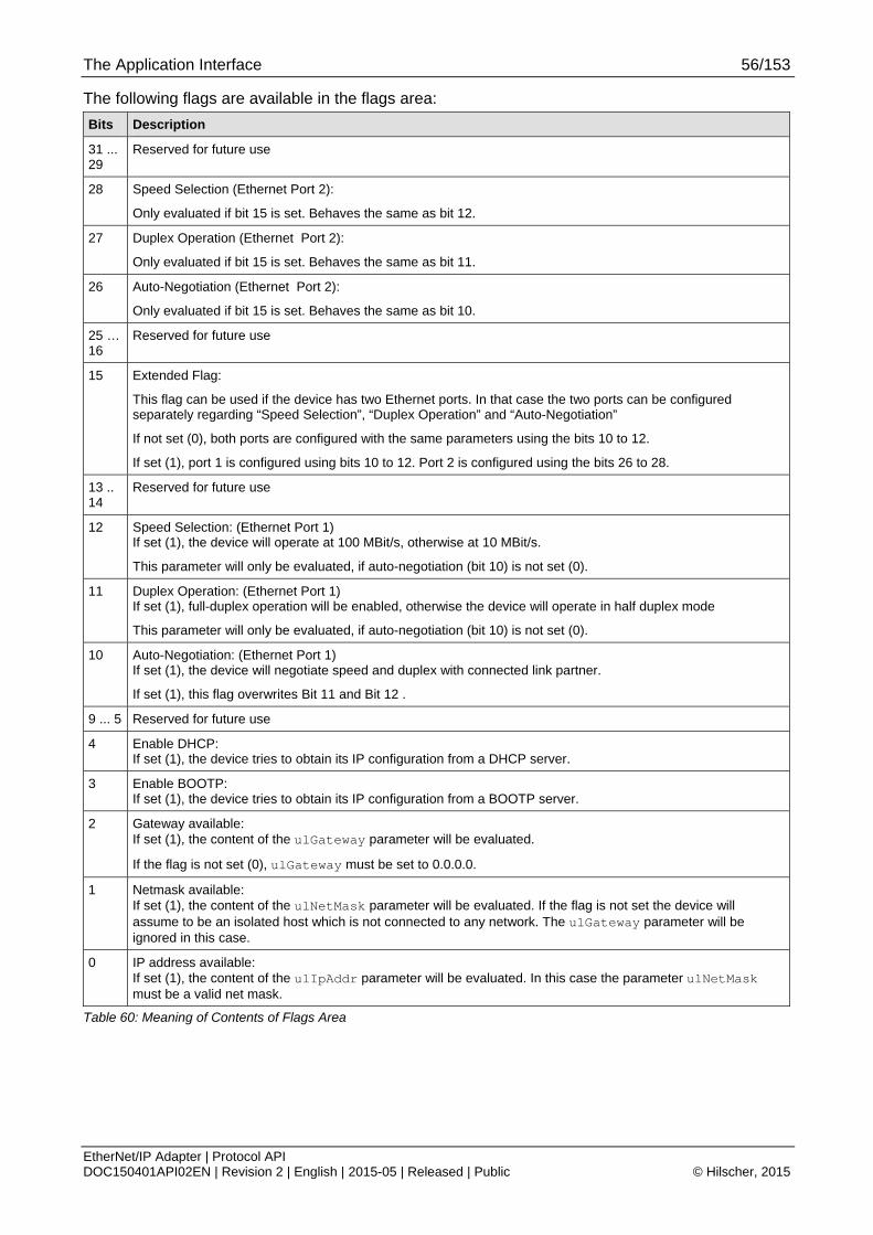
The Application Interface 56/153
EtherNet/IP Adapter | Protocol API DOC150401API02EN | Revision 2 | English | 2015-05 | Released | Public © Hilscher, 2015
The following flags are available in the flags area:
Bits Description
31 ... 29
Reserved for future use
28 Speed Selection (Ethernet Port 2):
Only evaluated if bit 15 is set. Behaves the same as bit 12.
27 Duplex Operation (Ethernet Port 2):
Only evaluated if bit 15 is set. Behaves the same as bit 11.
26 Auto-Negotiation (Ethernet Port 2):
Only evaluated if bit 15 is set. Behaves the same as bit 10.
25 … 16
Reserved for future use
15 Extended Flag:
This flag can be used if the device has two Ethernet ports. In that case the two ports can be configured separately regarding “Speed Selection”, “Duplex Operation” and “Auto-Negotiation”
If not set (0), both ports are configured with the same parameters using the bits 10 to 12.
If set (1), port 1 is configured using bits 10 to 12. Port 2 is configured using the bits 26 to 28.
13 .. 14
Reserved for future use
12 Speed Selection: (Ethernet Port 1) If set (1), the device will operate at 100 MBit/s, otherwise at 10 MBit/s.
This parameter will only be evaluated, if auto-negotiation (bit 10) is not set (0).
11 Duplex Operation: (Ethernet Port 1) If set (1), full-duplex operation will be enabled, otherwise the device will operate in half duplex mode
This parameter will only be evaluated, if auto-negotiation (bit 10) is not set (0).
10 Auto-Negotiation: (Ethernet Port 1) If set (1), the device will negotiate speed and duplex with connected link partner.
If set (1), this flag overwrites Bit 11 and Bit 12 .
9 ... 5 Reserved for future use
4 Enable DHCP: If set (1), the device tries to obtain its IP configuration from a DHCP server.
3 Enable BOOTP: If set (1), the device tries to obtain its IP configuration from a BOOTP server.
2 Gateway available: If set (1), the content of the ulGateway parameter will be evaluated.
If the flag is not set (0), ulGateway must be set to 0.0.0.0.
1 Netmask available: If set (1), the content of the ulNetMask parameter will be evaluated. If the flag is not set the device will assume to be an isolated host which is not connected to any network. The ulGateway parameter will be ignored in this case.
0 IP address available: If set (1), the content of the ulIpAddr parameter will be evaluated. In this case the parameter ulNetMask must be a valid net mask.
Table 60: Meaning of Contents of Flags Area

The Application Interface 57/153
EtherNet/IP Adapter | Protocol API DOC150401API02EN | Revision 2 | English | 2015-05 | Released | Public © Hilscher, 2015
The input assembly flags and the output assembly flags are defined as follows:
Flag Meaning
Bit 0 This flag is used internally and must be set to 0.
Bit 1 This flag is used internally and must be set to 0.
Bit 2 This flag is used internally and must be set to 0.
Bit 3 If set (1), the assembly instance’s real time format is modeless, i.e. it does not contain run/idle information.
If not set (0), the assembly instance’s real time format is the 32-Bit Run/Idle header.
Bit 4 This flag is used internally and must be set to 0
Bit 5 This flag is used internally and must be set to 0
Bit 6 This flag decides whether the assembly data which is mapped into the DPM memory area is cleared upon closing or timeout of the connection or whether the last sent/received data is left unchanged in the memory.
If the bit is set (1) the data will be left unchanged.
Bit 7 This flag decides whether the assembly instance allows a connection to be established with a smaller connection size than defined in ulInputLen/ulOutputLen or whether only the exact match is accepted. If the bit is set (1), the connection size in a ForwardOpen must directly correspond to ulInputLen/ulOutputLen.
Example:
1) ulInputLen = 16 (Bit 7 of ulInputAssFlags is not set (0)) ulOutputLen = 32 (Bit 7 of ulOutputAssFlags is not set (0)) A connection can be opened with smaller or matching I/O sizes, e.g. 8 for input and 20 for output.
2) ulInputLen = 6 (Bit 7 of ulInputAssFlags is set (1)) ulOutputLen = 10 (Bit 7 of ulOutputAssFlags is set (1)) A connection can only be opened with matching I/O sizes, 6 for input and 10 for output.
Table 61: Input Assembly Flags/ Output Assembly Flags

The Application Interface 58/153
EtherNet/IP Adapter | Protocol API DOC150401API02EN | Revision 2 | English | 2015-05 | Released | Public © Hilscher, 2015
Packet Structure Reference
typedef __PACKED_PRE struct EIP_APS_SET_CONFIGURATION_PARAMETERS_CNF_Ttag { TLR_UINT32 ulPacketVersion; /*!< Version related to the following union entry */ __PACKED_PRE union { EIP_APS_CONFIGURATION_PARAMETER_SET_V1_T tV1; EIP_APS_CONFIGURATION_PARAMETER_SET_V2_T tV2; EIP_APS_CONFIGURATION_PARAMETER_SET_V3_T tV3 }__PACKED_POST unConfig; }__PACKED_POST EIP_APS_SET_CONFIGURATION_PARAMETERS_CNF_T; typedef struct EIP_APS_PACKET_SET_CONFIGURATION_PARAMETERS_CNF_Ttag { TLR_PACKET_HEADER_T tHead; EIP_APS_SET_CONFIGURATION_PARAMETERS_CNF_T tData; } EIP_APS_PACKET_SET_CONFIGURATION_PARAMETERS_CNF_T;
Packet Description
Structure EIP_APS_PACKET_SET_CONFIGURATION_PARAMETERS_CNF_T Type: Confirmation
Variable Type Value / Range Description
tHead – Structure TLR_PACKET_HEADER_T
ulDest UINT32 See rules in section 3.2.1
Destination Queue Handle
ulSrc UINT32 See rules in section 3.2.1
Source Queue Handle
ulDestId UINT32 See rules in section 3.2.1
Destination Queue Reference
ulSrcId UINT32 See rules in section 3.2.1
Source Queue Reference
ulLen UINT32 Size from request packet
Packet Data Length in bytes
ulId UINT32 0 ... 232-1 Packet Identification as unique number generated by the Source Process of the Packet
ulSta UINT32 See chapter Status/Error Codes Overview
ulCmd UINT32 0x3613 EIP_APS_SET_CONFIGURATION_PARAMETERS_CNF - Command
ulExt UINT32 0 Extension not in use, set to zero for compatibility reasons
ulRout UINT32 x Routing, do not touch
tData - Structure EIP_APS_SET_CONFIGURATION_ PARAMETERS_CNF_T
ulParameterVersion
UINT32 Version of the following parameter structure (from request packet)
unConfig UNION
Configuration Set (from request packet)
Table 62: EIP_APS_PACKET_SET_CONFIGURATION_PARAMETERS_CNF – Set Configuration Parameters Confirmation

The Application Interface 59/153
EtherNet/IP Adapter | Protocol API DOC150401API02EN | Revision 2 | English | 2015-05 | Released | Public © Hilscher, 2015
4.1.2 Set Parameter Flags
This packet can be sent by the host application to activate special functionalities or behaviors of the AP-Task. The request packet therefore contains a flag field in which each bit stands for a specific functionality.
Table 63 shows all available flags:
Bit Description
0 Flag IP_APS_PRM_SIGNAL_MS_NS_CHANGE (0x00000001)
If set (1), the host application will be notified whenever the network or module status changes. The module and the network status are displayed by LEDs at EtherNet/IP devices (see section 6.1 “Module and Network Status” for more information). The notification will be sent with the indication packet Link Status Change.
If not set (0) no notifications will be sent.
1..31 Reserved for future use.
Table 63: EIP_APS_SET_PARAMETER_REQ Flags
Figure 6 below displays a sequence diagram for the EIP_APS_SET_PARAMETER_REQ/CNF packet.
Figure 6: Sequence diagram for the EIP_APS_SET_PARAMETER_REQ/CNF packet
Packet Structure Reference #define EIP_APS_PRM_SIGNAL_MS_NS_CHANGE 0x00000001 typedef struct EIP_APS_SET_PARAMETER_REQ_Ttag { TLR_UINT32 ulParameterFlags; /*!< Parameter flags \n } EIP_APS_SET_PARAMETER_REQ_T; #define EIP_APS_SET_PARAMETER_REQ_SIZE (sizeof(EIP_APS_SET_PARAMETER_REQ_T)) typedef struct EIP_APS_PACKET_SET_PARAMETER_REQ_Ttag { TLR_PACKET_HEADER_T tHead; EIP_APS_SET_PARAMETER_REQ_T tData; } EIP_APS_PACKET_SET_PARAMETER_REQ_T;

The Application Interface 60/153
EtherNet/IP Adapter | Protocol API DOC150401API02EN | Revision 2 | English | 2015-05 | Released | Public © Hilscher, 2015
Packet Description
structure EIP_APS_PACKET_SET_PARAMETER_REQ_T
Type: Request
Area Variable Type Value / Range Description
structure TLR_PACKET_HEADER_T
ulDest UINT32 0x20/ DPMINTF_QUE
Destination Queue-Handle
ulSrc UINT32 0 ... 232-1 Source Queue-Handle
ulDestId UINT32 See rules in section 3.2.1
Destination End Point Identifier, specifying the final receiver of the packet within the Destination Process. Set to 0 for the Initialization Packet
ulSrcId UINT32 See rules in section 3.2.1
Source End Point Identifier, specifying the origin of the packet inside the Source Process
ulLen UINT32 4 Packet Data Length in bytes
ulId UINT32 0 ... 232-1 Packet Identification as unique number generated by the Source Process of the Packet
ulSta UINT32 See Packet Structure Reference
ulCmd UINT32 0x360A EIP_APS_SET_PARAMETER_REQ - Command
ulExt UINT32 0 Extension not in use, set to zero for compatibility reasons
tHead
ulRout UINT32 x Routing, do not touch
structure EIP_APS_SET_PARAMETER_REQ_T tData
ulParameterFlags UINT32 See Table 63 for possible values
Bit field
Table 64: EIP_APS_SET_PARAMETER_REQ – Set Parameter Flags Request
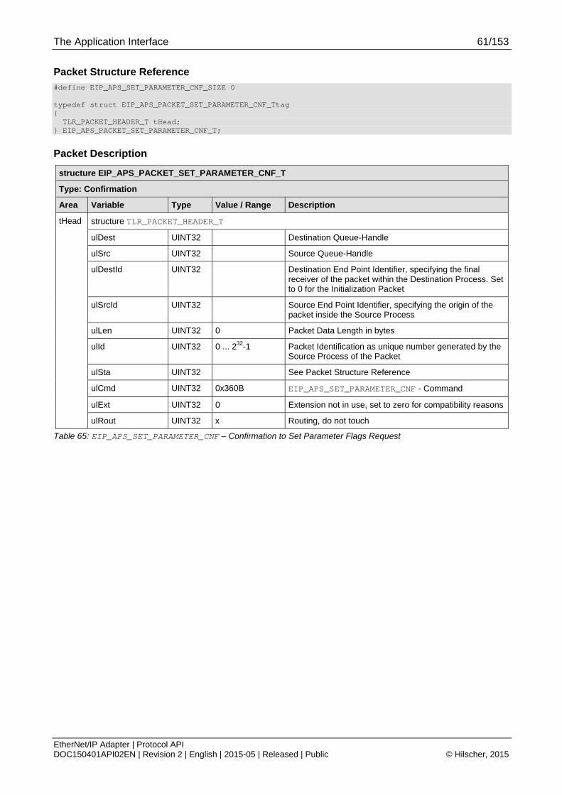
The Application Interface 61/153
EtherNet/IP Adapter | Protocol API DOC150401API02EN | Revision 2 | English | 2015-05 | Released | Public © Hilscher, 2015
Packet Structure Reference #define EIP_APS_SET_PARAMETER_CNF_SIZE 0 typedef struct EIP_APS_PACKET_SET_PARAMETER_CNF_Ttag { TLR_PACKET_HEADER_T tHead; } EIP_APS_PACKET_SET_PARAMETER_CNF_T;
Packet Description
structure EIP_APS_PACKET_SET_PARAMETER_CNF_T
Type: Confirmation
Area Variable Type Value / Range Description
structure TLR_PACKET_HEADER_T
ulDest UINT32 Destination Queue-Handle
ulSrc UINT32 Source Queue-Handle
ulDestId UINT32 Destination End Point Identifier, specifying the final receiver of the packet within the Destination Process. Set to 0 for the Initialization Packet
ulSrcId UINT32 Source End Point Identifier, specifying the origin of the packet inside the Source Process
ulLen UINT32 0 Packet Data Length in bytes
ulId UINT32 0 ... 232-1 Packet Identification as unique number generated by the Source Process of the Packet
ulSta UINT32 See Packet Structure Reference
ulCmd UINT32 0x360B EIP_APS_SET_PARAMETER_CNF - Command
ulExt UINT32 0 Extension not in use, set to zero for compatibility reasons
tHead
ulRout UINT32 x Routing, do not touch
Table 65: EIP_APS_SET_PARAMETER_CNF – Confirmation to Set Parameter Flags Request
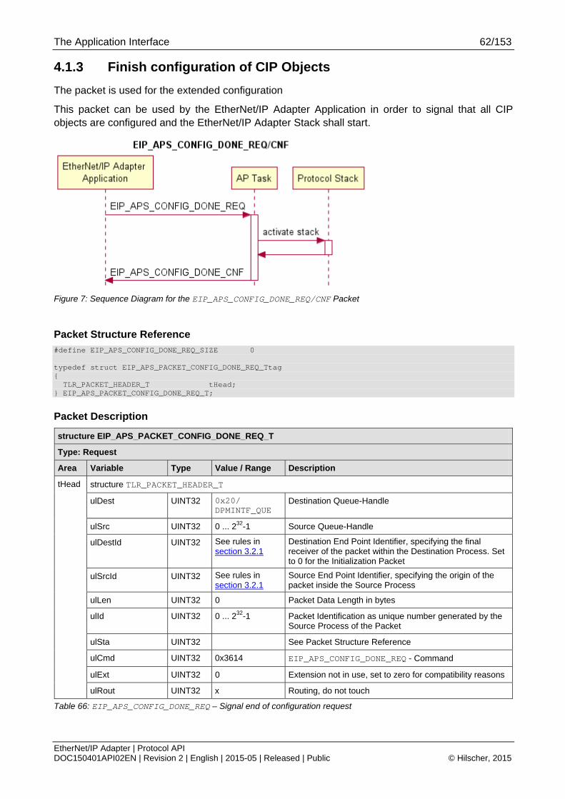
The Application Interface 62/153
EtherNet/IP Adapter | Protocol API DOC150401API02EN | Revision 2 | English | 2015-05 | Released | Public © Hilscher, 2015
4.1.3 Finish configuration of CIP Objects
The packet is used for the extended configuration
This packet can be used by the EtherNet/IP Adapter Application in order to signal that all CIP objects are configured and the EtherNet/IP Adapter Stack shall start.
Figure 7: Sequence Diagram for the EIP_APS_CONFIG_DONE_REQ/CNF Packet
Packet Structure Reference #define EIP_APS_CONFIG_DONE_REQ_SIZE 0 typedef struct EIP_APS_PACKET_CONFIG_DONE_REQ_Ttag { TLR_PACKET_HEADER_T tHead; } EIP_APS_PACKET_CONFIG_DONE_REQ_T;
Packet Description
structure EIP_APS_PACKET_CONFIG_DONE_REQ_T
Type: Request
Area Variable Type Value / Range Description
structure TLR_PACKET_HEADER_T
ulDest UINT32 0x20/ DPMINTF_QUE
Destination Queue-Handle
ulSrc UINT32 0 ... 232-1 Source Queue-Handle
ulDestId UINT32 See rules in section 3.2.1
Destination End Point Identifier, specifying the final receiver of the packet within the Destination Process. Set to 0 for the Initialization Packet
ulSrcId UINT32 See rules in section 3.2.1
Source End Point Identifier, specifying the origin of the packet inside the Source Process
ulLen UINT32 0 Packet Data Length in bytes
ulId UINT32 0 ... 232-1 Packet Identification as unique number generated by the Source Process of the Packet
ulSta UINT32 See Packet Structure Reference
ulCmd UINT32 0x3614 EIP_APS_CONFIG_DONE_REQ - Command
ulExt UINT32 0 Extension not in use, set to zero for compatibility reasons
tHead
ulRout UINT32 x Routing, do not touch
Table 66: EIP_APS_CONFIG_DONE_REQ – Signal end of configuration request

The Application Interface 63/153
EtherNet/IP Adapter | Protocol API DOC150401API02EN | Revision 2 | English | 2015-05 | Released | Public © Hilscher, 2015
Packet Structure Reference #define EIP_APS_CONFIG_DONE_CNF_SIZE 0 typedef struct EIP_APS_PACKET_CONFIG_DONE_CNF_Ttag { TLR_PACKET_HEADER_T tHead; } EIP_APS_PACKET_CONFIG_DONE_CNF_T;
Packet Description
structure EIP_APS_PACKET_CONFIG_DONE_CNF_T
Type: Confirmation
Area Variable Type Value / Range Description
structure TLR_PACKET_HEADER_T
ulDest UINT32 Destination Queue-Handle
ulSrc UINT32 Source Queue-Handle
ulDestId UINT32 Destination End Point Identifier, specifying the final receiver of the packet within the Destination Process. Set to 0 for the Initialization Packet
ulSrcId UINT32 Source End Point Identifier, specifying the origin of the packet inside the Source Process
ulLen UINT32 0 Packet Data Length in bytes
ulId UINT32 0 ... 232-1 Packet Identification as unique number generated by the Source Process of the Packet
ulSta UINT32 See Packet Structure Reference
ulCmd UINT32 0x3615 EIP_APS_CONFIG_DONE_CNF - Command
ulExt UINT32 0 Extension not in use, set to zero for compatibility reasons
tHead
ulRout UINT32 x Routing, do not touch
Table 67: EIP_APS_CONFIG_DONE_CNF – Confirmation of end of configuration Request

The Application Interface 64/153
EtherNet/IP Adapter | Protocol API DOC150401API02EN | Revision 2 | English | 2015-05 | Released | Public © Hilscher, 2015
4.1.4 Register an additional Object Class at the Message Router
This service can be used by the host application in order to register or activate an additional object class at the message router. This automatically extends the object model of the device by the given object class (see Figure 1 for the basic object model).
Basically, there are two types for additional objects that can be registered.
1) Register a CIP object that is provided by the stack (e.g. Time Sync obejct). In that case an object is activated that is completely handled by the stack (such as the Ethernet Link or TCP/IP Interface object).
2) Register a CIP object that is not known to the stack and therefore completely handled by the host application
For type 2 all explicit messages addressing this additional object class will then be forwarded to the host application via the indication EIP_OBJECT_CL3_SERVICE_IND (section 4.2.3).
Note: When using the Stack Packet Set:
The source queue of this packet is directly bound to the new object. All indications for the new object will be sent to ulSrc and ulSrcId of the request packet (packet header).
The ulClass parameter represents the class code of the registered class. The predefined class codes are described in the CIP specification Vol. 1 chapter 5.
CIP Class IDs are divided into the following address ranges to provide for extensions to device profiles.
Address Range Meaning
0x0001 - 0x0063 Open
0x0064 - 0x00C7 Vendor Specific
0x00C8 - 0x00EF Reserved by ODVA for future use
0x00F0 - 0x02FF Open
0x0300 - 0x04FF Vendor Specific
0x0500 - 0xFFFF Reserved by ODVA for future use
Table 68: Address Ranges for the ulClass parameter
Figure 8 below displays a sequence diagram for the EIP_OBJECT_MR_REGISTER_REQ/CNF packet.
Figure 8: Sequence Diagram for the EIP_OBJECT_MR_REGISTER_REQ/CNF Packet for the Stack Packet Set

The Application Interface 65/153
EtherNet/IP Adapter | Protocol API DOC150401API02EN | Revision 2 | English | 2015-05 | Released | Public © Hilscher, 2015
Packet Structure Reference typedef enum EIP_OBJECT_MR_REGISTER_OPTION_FLAGS_Etag { EIP_OBJECT_MR_REGISTER_OPTION_FLAGS_USE_OBJECT_PROVIDED_BY_STACK = 1, /* Activate a stack internal CIP object. This option can currently
be used for the following CIP objects - Time Sync object (class code 0x43) */ } EIP_OBJECT_MR_REGISTER_OPTION_FLAGS_E; typedef struct EIP_OBJECT_MR_REGISTER_REQ_Ttag { TLR_UINT32 ulReserved1; TLR_UINT32 ulClass; TLR_UINT32 ulOptionFlags; /* EIP_OBJECT_MR_REGISTER_OPTION_FLAGS_E */ } EIP_OBJECT_MR_REGISTER_REQ_T; #define EIP_OBJECT_MR_REGISTER_REQ_SIZE \ sizeof(EIP_OBJECT_MR_REGISTER_REQ_T) typedef struct EIP_OBJECT_MR_PACKET_REGISTER_REQ_Ttag { TLR_PACKET_HEADER_T tHead; EIP_OBJECT_MR_REGISTER_REQ_T tData; } EIP_OBJECT_MR_PACKET_REGISTER_REQ_T;
Packet Description
Structure EIP_OBJECT_PACKET_MR_REGISTER_REQ_T Type: Request
Variable Type Value / Range Description
tHead – Structure TLR_PACKET_HEADER_T
ulDest UINT32 0x20/ OBJECT_QUE
Destination Queue-Handle. Set to
0: Destination is operating system rcX 32 (0x20): Destination is the protocol stack
ulSrc UINT32 0 ... 232-1 Source Queue-Handle. Set to:
0: when working with loadable firmware. Queue handle returned by TLR_QUE_IDENTIFY(): when working with loadable firmware.
ulDestId UINT32 0 Destination End Point Identifier, specifying the final receiver of the packet within the Destination Process.
Set to 0, will not be changed
ulSrcId UINT32 0 ... 232-1 Source End Point Identifier, specifying the origin of the packet inside the Source Process. This variable may be used for low-level addressing purposes.
ulLen UINT32 12 EIP_OBJECT_MR_REGISTER_REQ_SIZE – Packet data length in bytes
ulId UINT32 0 ... 232-1 Packet Identification as unique number generated by the Source Process of the Packet
ulSta UINT32 See Table 44: EIP_OBJECT_MR_REGISTER_REQ – Packet Status/Error
ulCmd UINT32 0x1A02
EIP_OBJECT_MR_REGISTER_REQ - Command
ulExt UINT32 0 Extension not in use, set to zero for compatibility reasons
ulRout UINT32 × Routing, do not change
tData - Structure EIP_OBJECT_MR_REGISTER_REQ_T
ulReserved1 UINT32 0 Reserved, set to 0

The Application Interface 66/153
EtherNet/IP Adapter | Protocol API DOC150401API02EN | Revision 2 | English | 2015-05 | Released | Public © Hilscher, 2015
Structure EIP_OBJECT_PACKET_MR_REGISTER_REQ_T Type: Request
ulClass UINT32 1..0xFFFF Class identifier (predefined class code as described in the CIP specification Vol. 1 chapter 5 (reference [3]) Take care of the address ranges specified above within Table 68: Address Ranges for the ulClass parameter.
ulOptionFlags UINT32 For type 1, set to 0
For type 2, set flag EIP_OBJECT_MR_REGISTER_OPTION_FLAGS_USE_OBJECT_PROVIDED_BY_STACK
Additional CIP object that can be registered with type 2: - Time Sync object (class code 0x43)
Table 69: EIP_OBJECT_MR_REGISTER_REQ – Request Command for register a new class object
Packet Structure Reference typedef struct EIP_OBJECT_PACKET_MR_REGISTER_CNF_Ttag { TLR_PACKET_HEADER_T tHead; } EIP_OBJECT_PACKET_MR_REGISTER_CNF_T;
Packet Description
Structure EIP_OBJECT_PACKET_MR_REGISTER_CNF_T Type: Confirmation
Variable Type Value / Range Description
tHead – Structure TLR_PACKET_HEADER_T
ulDest UINT32 See rules in section 3.2.1
Destination Queue Handle
ulSrc UINT32 See rules in section 3.2.1
Source Queue Handle
ulDestId UINT32 See rules in section 3.2.1
Destination End Point Identifier, specifying the final receiver of the packet within the Destination Process.
ulSrcId UINT32 See rules in section 3.2.1
Source End Point Identifier, specifying the origin of the packet inside the Source Process
ulLen UINT32 0 Packet data length in bytes
ulId UINT32 0 ... 232-1 Packet Identification, unchanged
ulSta UINT32 See chapter Status/Error Codes Overview
ulCmd UINT32 0x1A03 EIP_OBJECT_MR_REGISTER_CNF - Command
ulExt UINT32 0 Extension, reserved
ulRout UINT32 See rules in section 3.2.1
Destination Queue Handle
Table 70: EIP_OBJECT_MR_REGISTER_CNF – Confirmation Command of register a new class object

The Application Interface 67/153
EtherNet/IP Adapter | Protocol API DOC150401API02EN | Revision 2 | English | 2015-05 | Released | Public © Hilscher, 2015
4.1.5 Register a new Assembly Instance
This service can be used by the host application in order to create a new Assembly Instance.
The parameter ulInstance is the assembly instance number that shall be registered at the assembly class object.
Instances of the assembly object are divided into the following address ranges:
Assembly Instance
Number Range
Meaning
0x0001 - 0x0063 Open (assemblies defined in device profile)
0x0064 - 0x00C7 Vendor Specific assemblies
0x00C8 - 0x02FF Open (assemblies defined in device profile)
0x0300 - 0x04FF Vendor Specific assemblies
0x0500 - 0x000FFFFF Open (assemblies defined in device profile)
0x00100000 - 0xFFFFFFFF Reserved by CIP for future use.
Table 71: Assembly Instance Number Ranges
Note: The instance numbers 192 and 193 (0xC0 and 0xC1) are the Hilscher’s default assembly instances for Listen Only and Input Only connections. These instance numbers must not be used for additional assembly instances at configuration with Basic Configuration Set.
Data belonging to this specific assembly instance will be mapped into the dual port memory at the offset address ulDPMOffset.
Note: This offset (ulDPMOffset) is not the total DPM offset. It is the relative offset within the beginning of the corresponding input/output data images abPd0Input[5760] and abPd0Output[5760] (see reference [1]).
So, usually the first instance (for each data direction) that is created will have ulDPMOffset = 0.
If multiple assembly instances are registered, make sure that the data range of these instances do not overlap in the DPM.
Note: When using the Basic Configuration Set default assemblies will be created on offset address 0.
The data length (in bytes) the assembly instance shall hold can be provided in ulSize. The size of an instance may not exceed 504 bytes.
The properties of the assembly instance can be configured using the parameter ulFlags. Properties can be set according to Table 73: Assembly Instance below.
As long as no data has ever been set and no connection has been established, the Assembly Object Instance holds zeroed data.
Figure 9 below displays a sequence diagram for the EIP_OBJECT_AS_REGISTER_REQ/CNF packet.

The Application Interface 68/153
EtherNet/IP Adapter | Protocol API DOC150401API02EN | Revision 2 | English | 2015-05 | Released | Public © Hilscher, 2015
Figure 9: Sequence Diagram for the EIP_OBJECT_AS_REGISTER_REQ/CNF Packet for the Stack Packet Set
Packet Structure Reference typedef struct EIP_OBJECT_AS_REGISTER_REQ_Ttag { TLR_UINT32 ulInstance; TLR_UINT32 ulDPMOffset; TLR_UINT32 ulSize; TLR_UINT32 ulFlags; } EIP_OBJECT_AS_REGISTER_REQ_T; #define EIP_OBJECT_AS_REGISTER_REQ_SIZE \ sizeof(EIP_OBJECT_AS_REGISTER_REQ_T) typedef struct EIP_OBJECT_AS_PACKET_REGISTER_REQ_Ttag { TLR_PACKET_HEADER_T tHead; EIP_OBJECT_AS_REGISTER_REQ_T tData; } EIP_OBJECT_AS_PACKET_REGISTER_REQ_T;

The Application Interface 69/153
EtherNet/IP Adapter | Protocol API DOC150401API02EN | Revision 2 | English | 2015-05 | Released | Public © Hilscher, 2015
Packet Description
Structure EIP_OBJECT_AS_PACKET_REGISTER_REQ_T Type: Request
Variable Type Value / Range Description
tHead – Structure TLR_PACKET_HEADER_T
ulDest UINT32 0, 0x20 Destination Queue-Handle. Set to
0: Destination is operating system rcX
32 (0x20): Destination is the protocol stack
ulSrc UINT32 0 ... 232-1 Source Queue-Handle. Set to:
0: when working with loadable firmware.
Queue handle returned by TLR_QUE_IDENTIFY(): when working with loadable firmware.
ulDestId UINT32 0 Destination End Point Identifier, specifying the final receiver of the packet within the Destination Process.
Set to 0, will not be changed
ulSrcId UINT32 0 ... 232-1 Source End Point Identifier, specifying the origin of the packet inside the Source Process. This variable may be used for low-level addressing purposes.
ulLen UINT32 16 EIP_OBJECT_AS_REGISTER_REQ_SIZE - Packet data length in bytes
ulId UINT32 0 ... 232-1 Packet Identification as unique number generated by the Source Process of the Packet
ulSta UINT32 See chapter Status/Error Codes Overview
ulCmd UINT32 0x1A0C EIP_OBJECT_AS_REGISTER_REQ - Command
ulExt UINT32 0 Extension not in use, set to zero for compatibility reasons
ulRout UINT32 × Routing, do not change
tData - Structure EIP_OBJECT_AS_REGISTER_REQ_T
ulInstance UINT32 0x0000001... 0xFFFFFFFF
(except 0xC0 and 0xC1, see description above)
Assembly instance number
See Table 71: Assembly Instance Number Ranges
ulDPMOffset UINT32 0..5760 DPM offset of the instance data area
Note:
This offset is not the total DPM offset. It is the relative offset within the beginning of the corresponding input/output data images abPd0Input[5760] and abPd0Output[5760]
So, usually the first instance (for each data direction) that is created will have ulDPMOffset = 0.
If multiple assembly instances are registered, make sure that the data range of these instances does not overlap in the DPM.
ulSize UINT32 1..504 Size of the data area for the assembly instance data.
ulFlags UINT32 Bitmap Property Flags for the assembly instance See Table 73: Assembly Instance
Table 72: EIP_OBJECT_AS_REGISTER_REQ – Request Command for create an Assembly Instance

The Application Interface 70/153
EtherNet/IP Adapter | Protocol API DOC150401API02EN | Revision 2 | English | 2015-05 | Released | Public © Hilscher, 2015
The following table shows the meaning of the single bits which can be used to configured specific assembly instance properties:
Bits Name (Bitmask) Description
31 EIP_AS_FLAG_LISTENONLY (0x80000000)
If the flag is set the instance is used as listen only connection point (heartbeat)
30 EIP_AS_FLAG_INPUTONLY (0x40000000)
If the flag is set the instance is used as input only connection point (heartbeat)
31...8 Reserved Reserved for future use
7 EIP_AS_FLAG_FIX_SIZE
(0x00000080)
This flag decides whether the assembly instance allows a connection to be established with a smaller connection size than defined in ulSize or whether only the exact match is accepted. If the bit is set (1), the connection size in a ForwardOpen must directly correspond to ulSize.
If the bit is not set (0), the connection size can be smaller or equal to ulSize.
Example:
1) ulSize = 16 (Bit 7 of ulFlags is 0) A connection to this assembly instance can be opened with a smaller or matching I/O size, e.g. 8.
2) ulSize = 6 (Bit 7 of ulFlags is 1) A connection can only be opened with a matching I/O size, i.e. 6.
6 Reserved Reserved for future use
5 EIP_AS_FLAG_CONFIG
(0x00000020)
If set (1), this assembly instance is a configuration assembly instance, which can be used to receive configuration data upon connection establishment.
Note:
Compared to input and output assembly instances a configuration instance is set only once via the Forward_Open frame. It is not exchange cyclically.
4 Reserved Reserved for future use
3 EIP_AS_FLAG_RUNIDLE
(0x00000008)
If set (1), the assembly instance’s real time format is modeless, i.e. it does not contain run/idle information.
If not set (0), the assembly instance’s real time format is the 32-Bit Run/Idle header.
0 EIP_AS_FLAG_READONLY
(0x00000001)
This flag decides whether the newly registered assembly is an input or an output assembly.
If set (1), the assembly instance is an output assembly instance (can be used for the OT direction). It is able to consume data from the network. Data for this instance will be mapped into the DPM Input area (data flow: network DPM).
If cleared (0), the assembly instance is an input assembly instance (can be used for the TO direction). It is able to produce data on the network. Data for this instance will be mapped from the DPM Output area (data flow: DPM network).
Table 73: Assembly Instance Property Flags

The Application Interface 71/153
EtherNet/IP Adapter | Protocol API DOC150401API02EN | Revision 2 | English | 2015-05 | Released | Public © Hilscher, 2015
Source Code Example
The following sample code shows how to fill in the parameter fields of the EIP_OBJECT_AS_REGISTER_REQ packet in order to create two assembly instances, one input and one output instance. /* Fill the EIP_OBJECT_AS_REGISTER_REQ packet to create an input (TO) assembly instance 100 that holds 16 bytes of data, has the modeless real-time format and does not allow smaller connection sizes. */ EIP_OBJECT_AS_PACKET_REGISTER_REQ_T tReq; tReq.tHead.ulCmd = EIP_OBJECT_AS_REGISTER_REQ; tReq.tHead.ulLen = EIP_OBJECT_AS_REGISTER_REQ_SIZE; tReq.tData.ulInstance = 100; tReq.tData.ulSize = 16; tReq.tData.ulFlags = EIP_AS_FLAG_MODELESS | EIP_AS_FLAG_FIX_SIZE; tReq.tData.ulDPMOffset = 0; /* Fill the EIP_OBJECT_AS_REGISTER_REQ packet to create an output (OT) assembly instance 101 that holds 8 bytes of data, has the run/idle realtime format and does allow smaller connection sizes. */ EIP_OBJECT_AS_PACKET_REGISTER_REQ_T tReq; tReq.tHead.ulCmd = EIP_OBJECT_AS_REGISTER_REQ; tReq.tHead.ulLen = EIP_OBJECT_AS_REGISTER_REQ_SIZE; tReq.tData.ulInstance = 101; tReq.tData.ulSize = 8; tReq.tData.ulFlags = EIP_AS_FLAG_READONLY; tReq.tData.ulDPMOffset = 0;

The Application Interface 72/153
EtherNet/IP Adapter | Protocol API DOC150401API02EN | Revision 2 | English | 2015-05 | Released | Public © Hilscher, 2015
Packet Structure Reference typedef struct EIP_OBJECT_AS_REGISTER_CNF_Ttag { TLR_UINT32 ulInstance; TLR_UINT32 ulDPMOffset; TLR_UINT32 ulSize; TLR_UINT32 ulFlags; TLR_HANDLE hDataBuf; } EIP_OBJECT_AS_REGISTER_CNF_T; #define EIP_OBJECT_AS_REGISTER_CNF_SIZE \ sizeof(EIP_OBJECT_AS_REGISTER_CNF_T) typedef struct EIP_OBJECT_PACKET_AS_REGISTER_CNF_Ttag { TLR_PACKET_HEADER_T tHead; } EIP_OBJECT_PACKET_AS_REGISTER_CNF_T;
Packet Description
Structure EIP_OBJECT_PACKET_AS_REGISTER_CNF_T Type: Confirmation
Variable Type Value / Range Description
tHead – Structure TLR_PACKET_HEADER_T
ulDest UINT32 See rules in section 3.2.1
Destination Queue-Handle, unchanged
ulSrc UINT32 See rules in section 3.2.1
Source Queue-Handle, unchanged
ulDestId UINT32 See rules in section 3.2.1
Destination End Point Identifier, specifying the final receiver of the packet within the Destination Process. Set to 0 for the Initialization Packet
ulSrcId UINT32 See rules in section 3.2.1
Source End Point Identifier, specifying the origin of the packet inside the Source Process
ulLen UINT32 20 EIP_OBJECT_AS_REGISTER_CNF_SIZE - Packet data length in bytes
ulId UINT32 0 ... 232-1 Packet Identification, unchanged
ulSta UINT32 See chapter Status/Error Codes Overview
ulCmd UINT32 0x1A0D EIP_OBJECT_AS_REGISTER_CNF - Command
ulExt UINT32 0 Extension, reserved
ulRout UINT32 × Routing, do not change
tData - Structure EIP_OBJECT_AS_REGISTER_CNF_T
ulInstance UINT32 Instance of the Assembly Object (from the request packet)
ulDPMOffset UINT32 Offset of the data in the dual port memory (from the request packet)
ulSize UINT32 <=504 Size of the assembly instance data (from the request packet)
ulFlags UINT32 Property Flags of the assembly instance (from the request packet)
hDataBuf UINT32 Handle to the tri-state buffer of the assembly instance
Table 74: EIP_OBJECT_AS_REGISTER_CNF – Confirmation Command of register a new class object
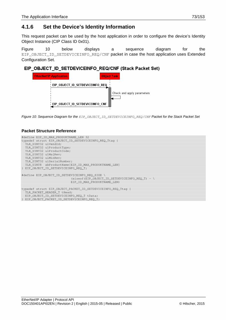
The Application Interface 73/153
EtherNet/IP Adapter | Protocol API DOC150401API02EN | Revision 2 | English | 2015-05 | Released | Public © Hilscher, 2015
4.1.6 Set the Device’s Identity Information
This request packet can be used by the host application in order to configure the device’s Identity Object Instance (CIP Class ID 0x01).
Figure 10 below displays a sequence diagram for the EIP_OBJECT_ID_SETDEVICEINFO_REQ/CNF packet in case the host application uses Extended Configuration Set.
Figure 10: Sequence Diagram for the EIP_OBJECT_ID_SETDEVICEINFO_REQ/CNF Packet for the Stack Packet Set
Packet Structure Reference #define EIP_ID_MAX_PRODUKTNAME_LEN 32 typedef struct EIP_OBJECT_ID_SETDEVICEINFO_REQ_Ttag { TLR_UINT32 ulVendId; TLR_UINT32 ulProductType; TLR_UINT32 ulProductCode; TLR_UINT32 ulMajRev; TLR_UINT32 ulMinRev; TLR_UINT32 ulSerialNumber; TLR_UINT8 abProductName[EIP_ID_MAX_PRODUKTNAME_LEN] } EIP_OBJECT_ID_SETDEVICEINFO_REQ_T; #define EIP_OBJECT_ID_SETDEVICEINFO_REQ_SIZE \ (sizeof(EIP_OBJECT_ID_SETDEVICEINFO_REQ_T) - \ EIP_ID_MAX_PRODUKTNAME_LEN) typedef struct EIP_OBJECT_PACKET_ID_SETDEVICEINFO_REQ_Ttag { TLR_PACKET_HEADER_T tHead; EIP_OBJECT_ID_SETDEVICEINFO_REQ_T tData; } EIP_OBJECT_PACKET_ID_SETDEVICEINFO_REQ_T;
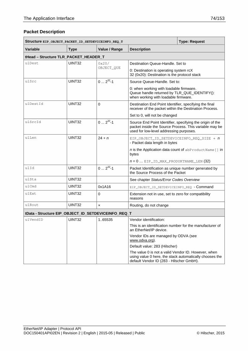
The Application Interface 74/153
EtherNet/IP Adapter | Protocol API DOC150401API02EN | Revision 2 | English | 2015-05 | Released | Public © Hilscher, 2015
Packet Description
Structure EIP_OBJECT_PACKET_ID_SETDEVICEINFO_REQ_T Type: Request
Variable Type Value / Range Description
tHead – Structure TLR_PACKET_HEADER_T
ulDest UINT32 0x20/ OBJECT_QUE
Destination Queue-Handle. Set to
0: Destination is operating system rcX 32 (0x20): Destination is the protocol stack
ulSrc UINT32 0 ... 232-1 Source Queue-Handle. Set to:
0: when working with loadable firmware. Queue handle returned by TLR_QUE_IDENTIFY(): when working with loadable firmware.
ulDestId UINT32 0 Destination End Point Identifier, specifying the final receiver of the packet within the Destination Process.
Set to 0, will not be changed
ulSrcId UINT32 0 ... 232-1 Source End Point Identifier, specifying the origin of the packet inside the Source Process. This variable may be used for low-level addressing purposes.
ulLen UINT32 24 + n EIP_OBJECT_ID_SETDEVICEINFO_REQ_SIZE + n - Packet data length in bytes
n is the Application data count of abProductName[] in bytes
n = 0 … EIP_ID_MAX_PRODUKTNAME_LEN (32)
ulId UINT32 0 ... 232-1 Packet Identification as unique number generated by the Source Process of the Packet
ulSta UINT32 See chapter Status/Error Codes Overview
ulCmd UINT32 0x1A16 EIP_OBJECT_ID_SETDEVICEINFO_REQ - Command
ulExt UINT32 0 Extension not in use, set to zero for compatibility reasons
ulRout UINT32 × Routing, do not change
tData - Structure EIP_OBJECT_ID_SETDEVICEINFO_REQ_T
ulVendID UINT32 1..65535 Vendor identification:
This is an identification number for the manufacturer of an EtherNet/IP device.
Vendor IDs are managed by ODVA (see www.odva.org).
Default value: 283 (Hilscher)
The value 0 is not a valid Vendor ID. However, when using value 0 here, the stack automatically chooses the default Vendor ID (283 - Hilscher GmbH).

The Application Interface 75/153
EtherNet/IP Adapter | Protocol API DOC150401API02EN | Revision 2 | English | 2015-05 | Released | Public © Hilscher, 2015
Structure EIP_OBJECT_PACKET_ID_SETDEVICEINFO_REQ_T Type: Request
ulProductType UINT32 0..65535 CIP Device Type (former “Product Type”)
The list of device types is managed by ODVA (see www.odva.org). It is used to identify the device profile that a particular product is using. Device profiles define minimum requirements a device must implement as well as common options.
Publicly defined: 0x00 - 0x64 Vendor specific: 0x64 - 0xC7 Reserved by CIP: 0xC8 - 0xFF Publicly defined: 0x100 - 0x2FF Vendor specific: 0x300 - 0x4FF Reserved by CIP: 0x500 - 0xFFFF Default: 0x0C (Communication Device)
The value 0 is not a valid Product Type. However, when using value 0 here, the stack automatically chooses the default Product Type (0x0C).
ulProductCode UINT32 1..65535 Product code
The vendor assigned Product Code identifies a particular product within a device type. Each vendor assigns this code to each of its products. The Product Code typically maps to one or more catalog/model numbers. Products shall have different codes if their configuration and/or runtime options are different. Such devices present a different logical view to the network. On the other hand for example, two products that are the same except for their color or mounting feet are the same logically and may share the same product code. The value zero is not valid.
The value 0 is not a valid Product Code. However, when using value 0 here, the stack automatically chooses the default Product Code dependent on the chip type (netX50/100 etc.) that is used.
ulMajRev UINT32 1..127 Major revision
ulMinRev UINT32 1..255 Minor revision
ulSerialNumber UINT32 0... 0xFFFFFFFF Serial Number of the device
This parameter is a number used in conjunction with the Vendor ID to form a unique identifier for each device on any CIP network. Each vendor is responsible for guaranteeing the uniqueness of the serial number across all of its devices. Usually, this number will be set automatically by the firmware, if a security memory is available. In this case leave this parameter at value 0.
abProductName[32] UINT8[] Product Name
This text string should represent a short description of the product/product family represented by the product code. The same product code may have a variety of product name strings.
Byte 0 indicates the length of the name. Bytes 1 -30 contain the characters of the device name)
Example: “Test Name” abDeviceName[0] = 9 abDeviceName[1..9] = “Test Name”
Table 75: EIP_OBJECT_ID_SETDEVICEINFO_REQ – Request Command for open a new connection
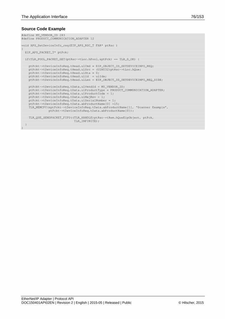
The Application Interface 76/153
EtherNet/IP Adapter | Protocol API DOC150401API02EN | Revision 2 | English | 2015-05 | Released | Public © Hilscher, 2015
Source Code Example #define MY_VENDOR_ID 283 #define PRODUCT_COMMUNICATION_ADAPTER 12 void APS_SetDeviceInfo_req(EIP_APS_RSC_T FAR* ptRsc ) { EIP_APS_PACKET_T* ptPck; if(TLR_POOL_PACKET_GET(ptRsc->tLoc.hPool,&ptPck) == TLR_S_OK) { ptPckt->tDeviceInfoReq.tHead.ulCmd = EIP_OBJECT_ID_SETDEVICEINFO_REQ; ptPckt->tDeviceInfoReq.tHead.ulSrc = (UINT32)ptRsc->tLoc.hQue; ptPckt->tDeviceInfoReq.tHead.ulSta = 0; ptPckt->tDeviceInfoReq.tHead.ulId = ulIdx; ptPckt->tDeviceInfoReq.tHead.ulLen = EIP_OBJECT_ID_SETDEVICEINFO_REQ_SIZE; ptPckt->tDeviceInfoReq.tData.ulVendId = MY_VENDOR_ID; ptPckt->tDeviceInfoReq.tData.ulProductType = PRODUCT_COMMUNICATION_ADAPTER; ptPckt->tDeviceInfoReq.tData.ulProductCode = 1; ptPckt->tDeviceInfoReq.tData.ulMajRev = 1; ptPckt->tDeviceInfoReq.tData.ulSerialNumber = 1; ptPckt->tDeviceInfoReq.tData.abProductName[0] =15; TLR_MEMCPY(&ptPckt->tDeviceInfoReq.tData.abProductName[1], “Scanner Example”, ptPckt->tDeviceInfoReq.tData.abProductName[0]); TLR_QUE_SENDPACKET_FIFO((TLR_HANDLE)ptRsc->tRem.hQueEipObject, ptPck, TLR_INFINITE); } }

The Application Interface 77/153
EtherNet/IP Adapter | Protocol API DOC150401API02EN | Revision 2 | English | 2015-05 | Released | Public © Hilscher, 2015
Packet Structure Reference typedef struct EIP_OBJECT_ID_SETDEVICEINFO_CNF_Ttag { TLR_PACKET_HEADER_T tHead; } EIP_OBJECT_PACKET_ID_SETDEVICEINFO_CNF_T;
Packet Description
Structure EIP_OBJECT_PACKET_ID_SETDEVICEINFO_CNF_T Type: Confirmation
Variable Type Value / Range Description
tHead – Structure TLR_PACKET_HEADER_T
ulDest UINT32 See rules in section 3.2.1
Destination Queue Handle
ulSrc UINT32 See rules in section 3.2.1
Source Queue Handle
ulDestId UINT32 See rules in section 3.2.1
Destination End Point Identifier, specifying the final receiver of the packet within the Destination Process.
ulSrcId UINT32 See rules in section 3.2.1
Source End Point Identifier, specifying the origin of the packet inside the Source Process
ulLen UINT32 0 Packet data length in bytes
ulId UINT32 0 ... 232-1 Packet Identification, unchanged
ulSta UINT32 See chapter Status/Error Codes Overview
ulCmd UINT32 0x1A17 EIP_OBJECT_ID_SETDEVICEINFO_CNF – Command
ulExt UINT32 0 Extension, reserved
ulRout UINT32 × Routing, do not change
Table 76: EIP_OBJECT_ID_SETDEVICEINFO_CNF – Confirmation Command of setting device information
Source Code Example void APS_SetDeviceInfo_cnf(EIP_APS_RSC_T FAR* ptRsc, EIP_APS_PACKET_T* ptPck ) { if( ptPck->tDeviceInfoCnf.tHead.ulSta != TLR_S_OK){ APS_ErrorHandling(ptRsc); } TLR_POOL_PACKET_RELEASE(ptRsc->tLoc.hPool, ptPck);

The Application Interface 78/153
EtherNet/IP Adapter | Protocol API DOC150401API02EN | Revision 2 | English | 2015-05 | Released | Public © Hilscher, 2015
4.1.7 Register Service
This packet can be used if the device shall support services that are not directly bound to a CIP object. Usually, services use the CIP addressing format ClassInstanceAtttribute. But if for example TAGs (access data within the device by using strings instead of the normal CIP addressing) shall be supported, no specific object can be addressed.
Therefore, the host application can register a vendor specific service code (see Table 98). If the device then receives this service (sent from a Scanner of Tool) it will be forwarded to the host application via the indication EIP_OBJECT_CL3_SERVICE_IND (section 4.2.3). Again, the indication is only sent if the service does not address an object directly.
Figure 11 below displays a sequence diagram for the EIP_OBJECT_REGISTER_SERVICE_REQ/CNF packet in case the host application uses the Extended or Stack Packet Set
Figure 11: Sequence Diagram for the EIP_OBJECT_REGISTER_SERVICE_REQ/CNF Packet for the Stack Packet Set

The Application Interface 79/153
EtherNet/IP Adapter | Protocol API DOC150401API02EN | Revision 2 | English | 2015-05 | Released | Public © Hilscher, 2015
Packet Structure Reference /* EIP_OBJECT_REGISTER_SERVICE_REQ */ struct EIP_OBJECT_REGISTER_SERVICE_REQ_Ttag { TLR_UINT32 ulService; /* Service Code */ }; /* command for register a new object to the message router */ struct EIP_OBJECT_PACKET_REGISTER_SERVICE_REQ_Ttag { TLR_PACKET_HEADER_T tHead; EIP_OBJECT_REGISTER_SERVICE_REQ_T tData; };
Packet Description
Structure EIP_OBJECT_PACKET_REGISTER_SERVICE_REQ_T Type: Request
Variable Type Value / Range Description
tHead – Structure TLR_PACKET_HEADER_T
ulDest UINT32 OBJECT_QUE Destination Queue-Handle. Set to
0: Destination is operating system rcX 32 (0x20): Destination is the protocol stack
ulSrc UINT32 0 ... 232-1 Source Queue-Handle. Set to:
0: when working with loadable firmware. Queue handle returned by TLR_QUE_IDENTIFY(): when working with loadable firmware.
ulDestId UINT32 0 Destination End Point Identifier, specifying the final receiver of the packet within the Destination Process.
Set to 0, will not be changed
ulSrcId UINT32 0 ... 232-1 Source End Point Identifier, specifying the origin of the packet inside the Source Process. This variable may be used for low-level addressing purposes.
ulLen UINT32 4 Packet Data Length (In Bytes)
ulId UINT32 0 ... 232-1 Packet Identification As Unique Number
ulSta UINT32 See chapter Status/Error Codes Overview
ulCmd UINT32 0x00001A44 EIP_OBJECT_REGISTER_SERVICE_REQ - Command / Response
ulExt UINT32 Reserved
ulRout UINT32 Routing Information
tData - structure EIP_OBJECT_REGISTER_SERVICE_REQ_T
ulService UINT32 Vendor specific service code (see Table 98)
Table 77: EIP_OBJECT_READY_REQ - Register Service
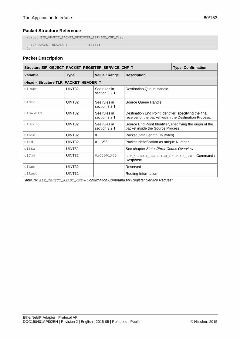
The Application Interface 80/153
EtherNet/IP Adapter | Protocol API DOC150401API02EN | Revision 2 | English | 2015-05 | Released | Public © Hilscher, 2015
Packet Structure Reference struct EIP_OBJECT_PACKET_REGISTER_SERVICE_CNF_Ttag { TLR_PACKET_HEADER_T tHead; };
Packet Description
Structure EIP_OBJECT_PACKET_REGISTER_SERVICE_CNF_T Type: Confirmation
Variable Type Value / Range Description
tHead – Structure TLR_PACKET_HEADER_T
ulDest UINT32 See rules in section 3.2.1
Destination Queue Handle
ulSrc UINT32 See rules in section 3.2.1
Source Queue Handle
ulDestId UINT32 See rules in section 3.2.1
Destination End Point Identifier, specifying the final receiver of the packet within the Destination Process.
ulSrcId UINT32 See rules in section 3.2.1
Source End Point Identifier, specifying the origin of the packet inside the Source Process
ulLen UINT32 0 Packet Data Length (In Bytes)
ulId UINT32 0 ... 232-1 Packet Identification as unique Number
ulSta UINT32 See chapter Status/Error Codes Overview
ulCmd UINT32 0x00001A45 EIP_OBJECT_REGISTER_SERVICE_CNF - Command / Response
ulExt UINT32 Reserved
ulRout UINT32 Routing Information
Table 78: EIP_OBJECT_READY_CNF – Confirmation Command for Register Service Request
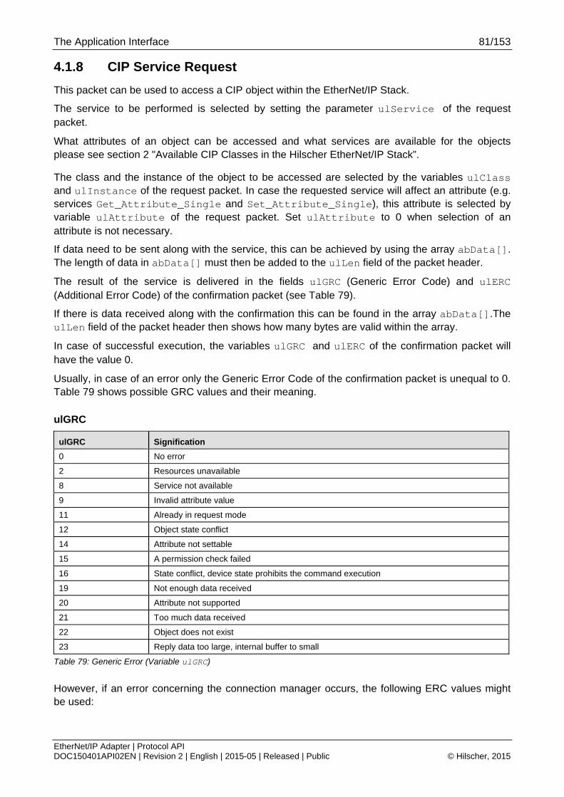
The Application Interface 81/153
EtherNet/IP Adapter | Protocol API DOC150401API02EN | Revision 2 | English | 2015-05 | Released | Public © Hilscher, 2015
4.1.8 CIP Service Request
This packet can be used to access a CIP object within the EtherNet/IP Stack.
The service to be performed is selected by setting the parameter ulService of the request packet.
What attributes of an object can be accessed and what services are available for the objects please see section 2 "Available CIP Classes in the Hilscher EtherNet/IP Stack”.
The class and the instance of the object to be accessed are selected by the variables ulClass and ulInstance of the request packet. In case the requested service will affect an attribute (e.g. services Get_Attribute_Single and Set_Attribute_Single), this attribute is selected by variable ulAttribute of the request packet. Set ulAttribute to 0 when selection of an attribute is not necessary.
If data need to be sent along with the service, this can be achieved by using the array abData[]. The length of data in abData[] must then be added to the ulLen field of the packet header.
The result of the service is delivered in the fields ulGRC (Generic Error Code) and ulERC (Additional Error Code) of the confirmation packet (see Table 79).
If there is data received along with the confirmation this can be found in the array abData[].The ulLen field of the packet header then shows how many bytes are valid within the array.
In case of successful execution, the variables ulGRC and ulERC of the confirmation packet will have the value 0.
Usually, in case of an error only the Generic Error Code of the confirmation packet is unequal to 0. Table 79 shows possible GRC values and their meaning.
ulGRC
ulGRC Signification
0 No error
2 Resources unavailable
8 Service not available
9 Invalid attribute value
11 Already in request mode
12 Object state conflict
14 Attribute not settable
15 A permission check failed
16 State conflict, device state prohibits the command execution
19 Not enough data received
20 Attribute not supported
21 Too much data received
22 Object does not exist
23 Reply data too large, internal buffer to small
Table 79: Generic Error (Variable ulGRC)
However, if an error concerning the connection manager occurs, the following ERC values might be used:

The Application Interface 82/153
EtherNet/IP Adapter | Protocol API DOC150401API02EN | Revision 2 | English | 2015-05 | Released | Public © Hilscher, 2015
ulERC
ulERC Signification
0 No error
0x100 Connection already in use
0x103 Transport type not supported
0x106 Multiple configuration attempts
0x107 Trying to close inactive connection
0x108 Unsupported connection type
0x109 Connection size mismatch
0x110 Connection unconfigured
0x111 Unsupportable RPI
0x113 Conn Mgr out of connections
0x114 Mismatch in electronic key
0x115 Mismatch in electronic key
0x116 Mismatch in electronic key
0x117 Nonexistant instance number
0x118 Bad config instance number
0x119 No controlling connection open
0x11A Application out of connections
0x11C The transport class requested in the Transport Type/Trigger parameter is not supported.
0x11D The production trigger requested in the Transport Type/Trigger parameter is not supported.
0x11E The direction requested in the Transport Type/Trigger parameter is not supported.
0x11F This extended status code shall be returned as the result of specifying an O2T fixed / variable flag that is not supported.
0x120 This extended status code shall be returned as the result of specifying a T2O fixed / variable flag that is not supported.
0x121 This extended status code shall be returned as the result of specifying an O2T priority code that is not supported.
0x122 This extended status code shall be returned as the result of specifying a T2O priority code that is not supported. */
0x123 This extended status code shall be returned as the result of specifying an O2T connection type that is not supported
0x124 This extended status code shall be returned as the result of specifying a T2O connection type that is not supported
0x125 This extended status code shall be returned as the result of specifying an O2T Redundant Owner flag that is not supported
0x126 This extended status code is returned when the target device determines that the data segment provided in the Connection_Path parameter did not contain an acceptable number of 16-bit words for the the configuration application path requested.
0x127 This extended status code is returned by the target when the size of the consuming object declared in the Forward_Open request and available on the target does not match the size declared in the O->T Network Connection Parameter. */
0x128 This extended status code is returned by the target when the size of the producing object declared in the Forward Open request and available on the target does not match the size declared in the T->O Network Connection Parameter.
0x129
The configuration application path specified in the connection path does not correspond to a valid configuration application path within the target application. This error could also be returned if a configuration application path was required, but not provided by a connection request
0x12A The consumed application path specified in the connection path does not correspond to a valid consumed application path within the target application. This error could also be

The Application Interface 83/153
EtherNet/IP Adapter | Protocol API DOC150401API02EN | Revision 2 | English | 2015-05 | Released | Public © Hilscher, 2015
ulERC Signification
returned if a consumed application path was required, but not provided by a connection request */
0x12B
The produced application path specified in the connection path does not correspond to a valid produced application path within the target application. This error could also be returned if a produced application path was required, but not provided by a connection request.
0x12C Configuration Symbol does not exist. The originator attempts to connect to a configuration tag name, but the name is not on the list of tags defined on the target. */
0x12D Consuming Symbol does not exist. The originator attempts to connect to a consuming tag name, but the name is not on the list of tags defined on the target. */
0x12E Producing Symbol does not exist. The originator attempts to connect to a producing tag name, but the name is not on the list of tags defined on the target. */
0x12F The combination of configuration and/or consume and/or produce application paths specified in the connection path are inconsistent with each other.
0x130 Information in the data segment is not consistent with the format of the consumed data. For example the configuration data specifies float configuration data while the consumed path specifies integer data.
0x131 Information in the data segment is not consistent with the format of the produced data. For example the configuration data specifies float configuration data while the produced path specifies integer data. */
0x203 Using a timed out connection
0x204 Unconnected Send timed out
0x205 Unconnected Send param. error
0x301 No buffer memory available
0x302 Insufficient bandwidth left
0x303 Out of gen screeners
0x304 Not configured to send RT data
0x305 sig does not match sig store in CCM
0x306 ccm is not responding to req
0x311 Nonexistent port
0x312 Invalid link address in path
0x315 Invalid segment in path
0x316 Path & conn not equal in close
0x317 Net seg not present or bad
0x318 Link address to self invalid
0x319 Resources in secondary unavail
0x31D Redundant connection mismatch
0x813 A multicast connection has been requested between a producer and a consumer that are on different subnets, and the producer is not configured for off-subnet multicast.
Table 80: Extended error codes for the connection manager
Figure 12 below displays a sequence diagram for the EIP_OBJECT_CIP_SERVICE_REQ/CNF packet: in case the host application uses the Basic, Extended or Stack Packet Set (see 3.2 “Configuration Using the Packet API”).
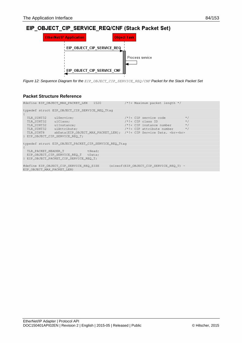
The Application Interface 84/153
EtherNet/IP Adapter | Protocol API DOC150401API02EN | Revision 2 | English | 2015-05 | Released | Public © Hilscher, 2015
Figure 12: Sequence Diagram for the EIP_OBJECT_CIP_SERVICE_REQ/CNF Packet for the Stack Packet Set
Packet Structure Reference #define EIP_OBJECT_MAX_PACKET_LEN 1520 /*!< Maximum packet length */ typedef struct EIP_OBJECT_CIP_SERVICE_REQ_Ttag { TLR_UINT32 ulService; /*!< CIP service code */ TLR_UINT32 ulClass; /*!< CIP class ID */ TLR_UINT32 ulInstance; /*!< CIP instance number */ TLR_UINT32 ulAttribute; /*!< CIP attribute number */ TLR_UINT8 abData[EIP_OBJECT_MAX_PACKET_LEN]; /*!< CIP Service Data. <br><br> } EIP_OBJECT_CIP_SERVICE_REQ_T; typedef struct EIP_OBJECT_PACKET_CIP_SERVICE_REQ_Ttag { TLR_PACKET_HEADER_T tHead; EIP_OBJECT_CIP_SERVICE_REQ_T tData; } EIP_OBJECT_PACKET_CIP_SERVICE_REQ_T; #define EIP_OBJECT_CIP_SERVICE_REQ_SIZE (sizeof(EIP_OBJECT_CIP_SERVICE_REQ_T) - EIP_OBJECT_MAX_PACKET_LEN)

The Application Interface 85/153
EtherNet/IP Adapter | Protocol API DOC150401API02EN | Revision 2 | English | 2015-05 | Released | Public © Hilscher, 2015
Packet Description
Structure EIP_OBJECT_PACKET_CIP_SERVICE_REQ_T Type: Request
Variable Type Value / Range Description
tHead - Structure TLR_PACKET_HEADER_T
ulDest UINT32 0x20/ OBJECT_QUE
Destination Queue-Handle. Set to
0: Destination is operating system rcX
32 (0x20): Destination is the protocol stack
ulSrc UINT32 0 ... 232-1 Source Queue-Handle. Set to:
0: when working with loadable firmware.
Queue handle returned by TLR_QUE_IDENTIFY(): when working with loadable firmware.
ulDestId UINT32 0 Destination End Point Identifier, specifying the final receiver of the packet within the Destination Process. Set to 0 for the Initialization Packet
ulSrcId UINT32 0 ... 232-1 Source End Point Identifier, specifying the origin of the packet inside the Source Process
ulLen UINT32 16+n Packet Data Length in bytes n = Length of service data in bytes (see field abData[])
ulId UINT32 0 ... 232-1 Packet Identification as unique number generated by the Source Process of the Packet
ulSta UINT32 See chapter Status/Error Codes Overview
ulCmd UINT32 0x1AF8 EIP_OBJECT_CIP_SERVICE_REQ - Command
ulExt UINT32 0 Extension not in use, set to zero for compatibility reasons
ulRout UINT32 x Routing, do not touch
tData - Structure EIP_OBJECT_CIP_SERVICE_REQ_T
ulService UINT32 1-31 CIP Service Code
ulClass UINT32 Valid Class ID CIP Class ID (according to “The CIP Networks Library, Volume 1 Common Industrial Protocol Specification Chapter 5, Table 5-1.1”)
For available object classes see section 2 “Available CIP Classes in the Hilscher EtherNet/IP Stack” on page 12.
ulInstance UINT32 Valid Instance number
CIP Object Instance number.
For available object classes and instances see section 2 “Available CIP Classes in the Hilscher EtherNet/IP Stack” on page 12.
ulAttribute UINT32 Valid Attribute number
CIP Attribute number (required for get/set attribute only, otherwise set it to 0)).
For available object classes and attributes see section 2 “Available CIP Classes in the Hilscher EtherNet/IP Stack” on page 12.
abData[1520] UINT8[ ] 0-1520 CIP Service data
Number of bytes n provided in this field must be added to the packet header length field ulLen.
Set the proper packet length as follows: ptReq->tHead.ulLen = EIP_OBJECT_CIP_SERVICE_REQ_SIZE + n
Table 81: EIP_OBJECT_CIP_SERVICE_REQ – CIP Service Request
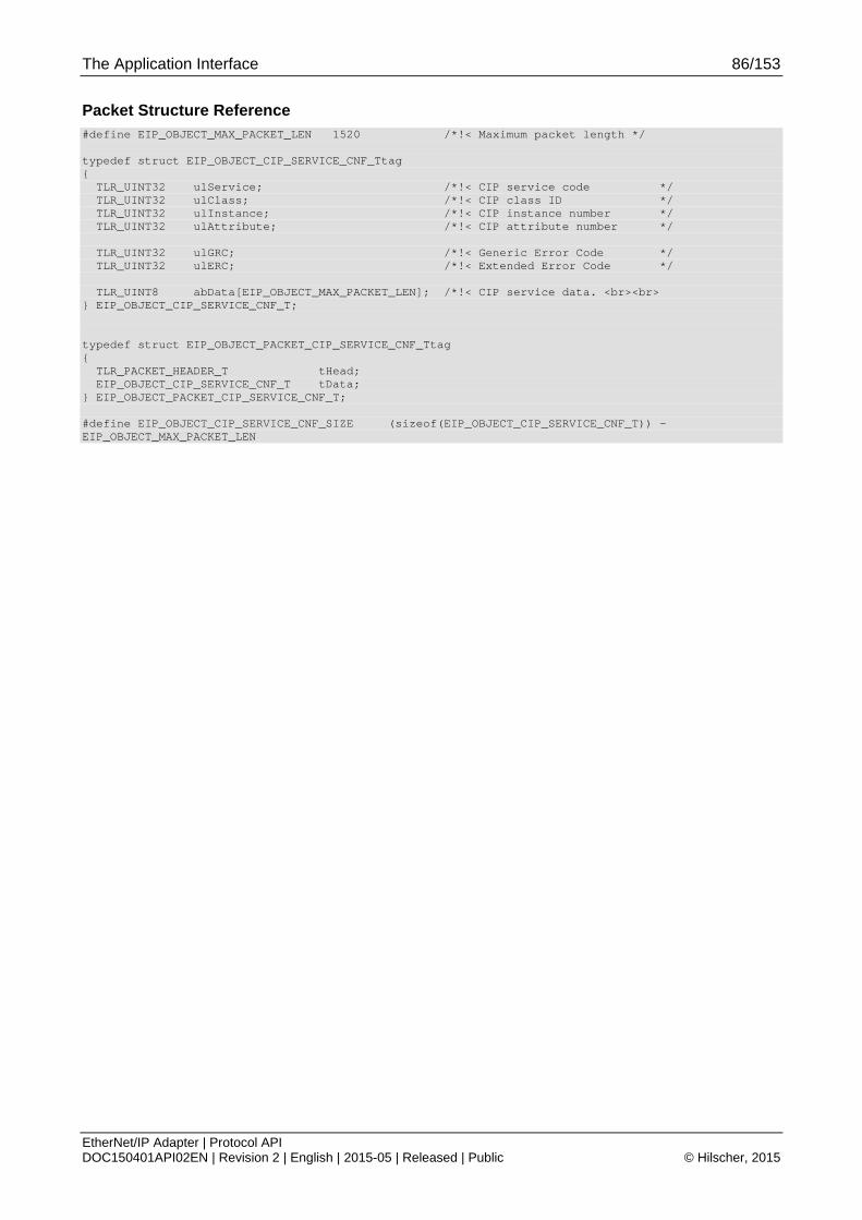
The Application Interface 86/153
EtherNet/IP Adapter | Protocol API DOC150401API02EN | Revision 2 | English | 2015-05 | Released | Public © Hilscher, 2015
Packet Structure Reference #define EIP_OBJECT_MAX_PACKET_LEN 1520 /*!< Maximum packet length */ typedef struct EIP_OBJECT_CIP_SERVICE_CNF_Ttag { TLR_UINT32 ulService; /*!< CIP service code */ TLR_UINT32 ulClass; /*!< CIP class ID */ TLR_UINT32 ulInstance; /*!< CIP instance number */ TLR_UINT32 ulAttribute; /*!< CIP attribute number */ TLR_UINT32 ulGRC; /*!< Generic Error Code */ TLR_UINT32 ulERC; /*!< Extended Error Code */ TLR_UINT8 abData[EIP_OBJECT_MAX_PACKET_LEN]; /*!< CIP service data. <br><br> } EIP_OBJECT_CIP_SERVICE_CNF_T; typedef struct EIP_OBJECT_PACKET_CIP_SERVICE_CNF_Ttag { TLR_PACKET_HEADER_T tHead; EIP_OBJECT_CIP_SERVICE_CNF_T tData; } EIP_OBJECT_PACKET_CIP_SERVICE_CNF_T; #define EIP_OBJECT_CIP_SERVICE_CNF_SIZE (sizeof(EIP_OBJECT_CIP_SERVICE_CNF_T)) - EIP_OBJECT_MAX_PACKET_LEN

The Application Interface 87/153
EtherNet/IP Adapter | Protocol API DOC150401API02EN | Revision 2 | English | 2015-05 | Released | Public © Hilscher, 2015
Packet Description
Structure EIP_OBJECT_PACKET_CIP_SERVICE_CNF_T Type: Confirmation
Variable Type Value / Range Description
tHead - Structure TLR_PACKET_HEADER_T
ulDest UINT32 See rules in section 3.2.1
Destination Queue Handle
ulSrc UINT32 See rules in section 3.2.1
Source Queue Handle
ulDestId UINT32 0 Destination End Point Identifier
ulSrcId UINT32 x Source End Point Identifier
ulLen UINT32 24+n Packet Data Length in bytes n = Length of service data in bytes
ulId UINT32 0 ... 232-1 Packet Identification as unique number generated by the Source Process of the Packet
ulSta UINT32 See chapter Status/Error Codes Overview
ulCmd UINT32 0x1AF9 EIP_OBJECT_CIP_SERVICE_CNF - Command
ulExt UINT32 0 Extension not in use, set to zero for compatibility reasons
ulRout UINT32 x Routing, do not touch
tData - Structure EIP_OBJECT_CIP_SERVICE_CNF_T
ulService UINT32 1-31 CIP Service Code
ulClass UINT32 Valid Class ID CIP Class ID (according to “The CIP Networks Library, Volume 1 Common Industrial Protocol Specification Chapter 5, Table 5-1.1”
ulInstance UINT32 Valid Instance number
CIP Instance number
ulAttribute UINT32 Valid Attribute number
CIP Attribute number (for get/set attribute only)
ulGRC UINT32 Generic error code. (according to “The CIP Networks Library, Volume 1 Common Industrial Protocol Specification Chapter 5, Appendix B-1. Volume 1) (see also Table 79)
ulERC UINT32 Additional error code.
abData[1520] UINT8[ ] CIP Service data
Number of bytes provided in this field must be calculated using the packet header length field ulLen.
Proceed as follows to get the data size:
number of bytes provided in abData = tHead.ulLen - EIP_OBJECT_CIP_SERVICE_REQ_SIZE
Table 82: EIP_OBJECT_CIP_SERVICE_CNF – Confirmation to CIP Service Request
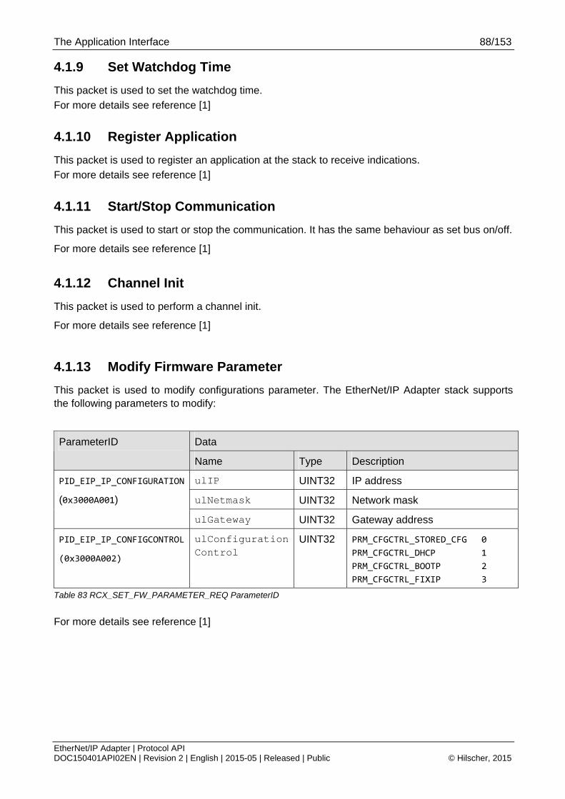
The Application Interface 88/153
EtherNet/IP Adapter | Protocol API DOC150401API02EN | Revision 2 | English | 2015-05 | Released | Public © Hilscher, 2015
4.1.9 Set Watchdog Time
This packet is used to set the watchdog time.
For more details see reference [1]
4.1.10 Register Application
This packet is used to register an application at the stack to receive indications.
For more details see reference [1]
4.1.11 Start/Stop Communication
This packet is used to start or stop the communication. It has the same behaviour as set bus on/off.
For more details see reference [1]
4.1.12 Channel Init
This packet is used to perform a channel init.
For more details see reference [1]
4.1.13 Modify Firmware Parameter
This packet is used to modify configurations parameter. The EtherNet/IP Adapter stack supports the following parameters to modify:
Data ParameterID
Name Type Description
ulIP UINT32 IP address
ulNetmask UINT32 Network mask
PID_EIP_IP_CONFIGURATION
(0x3000A001)
ulGateway UINT32 Gateway address
PID_EIP_IP_CONFIGCONTROL
(0x3000A002)
ulConfigurationControl
UINT32 PRM_CFGCTRL_STORED_CFG 0
PRM_CFGCTRL_DHCP 1
PRM_CFGCTRL_BOOTP 2
PRM_CFGCTRL_FIXIP 3
Table 83 RCX_SET_FW_PARAMETER_REQ ParameterID
For more details see reference [1]

The Application Interface 89/153
EtherNet/IP Adapter | Protocol API DOC150401API02EN | Revision 2 | English | 2015-05 | Released | Public © Hilscher, 2015
4.2 Acyclic events indicated by the stack
This chapter explains the events indicated by the stack. Depending on the configuration the stack sends the following indications:
Overview over the indications of the EtherNet/IP Adapter
No. of section
Packet Command code (REQ/CNF or IND/RES)
Page
4.2.1 EIP_OBJECT_RESET_IND 0x00001A24 90
4.2.2 EIP_OBJECT_CONNECTION_IND 0x00001A2E 94
4.2.3 EIP_OBJECT_CL3_SERVICE_IND 0x00001A3E 103
4.2.4 EIP_OBJECT_CIP_OBJECT_CHANGE_IND 0x00001AFA 116
4.2.5 RCX_LINK_STATUS_CHANGE_IND 0x00002F8A 119
Table 84: Overview over the indications of the EtherNet/IP Adapter
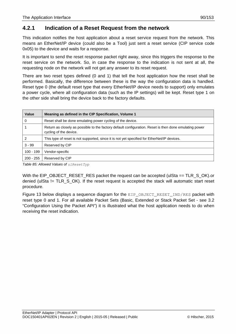
The Application Interface 90/153
EtherNet/IP Adapter | Protocol API DOC150401API02EN | Revision 2 | English | 2015-05 | Released | Public © Hilscher, 2015
4.2.1 Indication of a Reset Request from the network
This indication notifies the host application about a reset service request from the network. This means an EtherNet/IP device (could also be a Tool) just sent a reset service (CIP service code 0x05) to the device and waits for a response.
It is important to send the reset response packet right away, since this triggers the response to the reset service on the network. So, in case the response to the indication is not sent at all, the requesting node on the network will not get any answer to its reset request.
There are two reset types defined (0 and 1) that tell the host application how the reset shall be performed. Basically, the difference between these is the way the configuration data is handled. Reset type 0 (the default reset type that every EtherNet/IP device needs to support) only emulates a power cycle, where all configuration data (such as the IP settings) will be kept. Reset type 1 on the other side shall bring the device back to the factory defaults.
Value Meaning as defined in the CIP Specification, Volume 1
0 Reset shall be done emulating power cycling of the device.
1 Return as closely as possible to the factory default configuration. Reset is then done emulating power cycling of the device.
2 This type of reset is not supported, since it is not yet specified for EtherNet/IP devices.
3 - 99 Reserved by CIP
100 - 199 Vendor-specific
200 - 255 Reserved by CIP
Table 85: Allowed Values of ulResetTyp
With the EIP_OBJECT_RESET_RES packet the request can be accepted (ulSta == TLR_S_OK).or denied (ulSta != TLR_S_OK). If the reset request is accepted the stack will automatic start reset procedure.
Figure 13 below displays a sequence diagram for the EIP_OBJECT_RESET_IND/RES packet with reset type 0 and 1. For all available Packet Sets (Basic, Extended or Stack Packet Set - see 3.2 “Configuration Using the Packet API”) it is illustrated what the host application needs to do when receiving the reset indication.

The Application Interface 91/153
EtherNet/IP Adapter | Protocol API DOC150401API02EN | Revision 2 | English | 2015-05 | Released | Public © Hilscher, 2015
Figure 13: Sequence Diagram for the EIP_OBJECT_RESET_IND/RES Packet for the Basic Packet Set
Packet Structure Reference struct EIP_OBJECT_RESET_IND_Ttag { TLR_UINT32 ulDataIdx; /*!< Index of the service */ TLR_UINT32 ulResetTyp; /*!< Type of the reset */ }; struct EIP_OBJECT_PACKET_RESET_IND_Ttag { TLR_PACKET_HEADER_T tHead; EIP_OBJECT_RESET_IND_T Data; };

The Application Interface 92/153
EtherNet/IP Adapter | Protocol API DOC150401API02EN | Revision 2 | English | 2015-05 | Released | Public © Hilscher, 2015
Packet Description
Structure EIP_OBJECT_PACKET_RESET_IND_T Type: Indication
Variable Type Value / Range Description
tHead – Structure TLR_PACKET_HEADER_T
ulDest UINT32 Destination Queue-Handle. Set to
0: Destination is operating system rcX
32 (0x20): Destination is the protocol stack
ulSrc UINT32 Source Queue-Handle. Set to:
0: when working with loadable firmware.
Queue handle returned by TLR_QUE_IDENTIFY(): when working with loadable firmware.
ulDestId UINT32 Destination End Point Identifier, specifying the final receiver of the packet within the Destination Process.
Set to 0, will not be changed
ulSrcId UINT32 Source End Point Identifier, specifying the origin of the packet inside the Source Process. This variable may be used for low-level addressing purposes.
ulLen UINT32 8 Packet Data Length (In Bytes)
ulId UINT32 0 ... 232-1 Packet Identification As Unique Number
ulSta UINT32 See chapter Status/Error Codes Overview
ulCmd UINT32 0x00001A24 EIP_OBJECT_RESET_IND - Command / Response
ulExt UINT32 Reserved
ulRout UINT32 Routing Information
tData - structure EIP_OBJECT_RESET_IND_T
ulDataIdx UINT32 Index of the service (host application does not need to evaluate this parameter)
ulResetTyp UINT32 0..1, 100-199 Type of the reset
0: Reset is done emulating power cycling of the device(default)
1: Return as closely as possible to the factory default configuration. Reset is then done emulating power cycling of the device.
100-199: Vendor specific
Table 86: EIP_OBJECT_RESET_IND – Reset Request from Bus Indication

The Application Interface 93/153
EtherNet/IP Adapter | Protocol API DOC150401API02EN | Revision 2 | English | 2015-05 | Released | Public © Hilscher, 2015
Packet Structure Reference typedef struct EIP_OBJECT_PACKET_CONNECTION_RES_Ttag { TLR_PACKET_HEADER_T tHead; } EIP_OBJECT_PACKET_CONNECTION_RES_T;
Packet Description
Structure EIP_OBJECT_PACKET_RESET_RES_T Type: Response
Variable Type Value / Range Description
tHead – Structure TLR_PACKET_HEADER_T
ulDest UINT32 See rules in section 3.2.1
Destination Queue Handle
ulSrc UINT32 See rules in section 3.2.1
Source Queue Handle
ulDestId UINT32 See rules in section 3.2.1
Destination End Point Identifier, specifying the final receiver of the packet within the Destination Process.
ulSrcId UINT32 See rules in section 3.2.1
Source End Point Identifier, specifying the origin of the packet inside the Source Process
ulLen UINT32 0 Packet Data Length (In Bytes)
ulId UINT32 0 ... 232-1 Packet Identification As Unique Number
ulSta UINT32 TLR_S_OK, TLR_E_FAIL
See chapter Status/Error Codes Overview TLR_S_OK – reset is accepted TLR_E_FAIL – reset is denied
ulCmd UINT32 0x00001A25 EIP_OBJECT_RESET_RES – Response
ulExt UINT32 Reserved
ulRout UINT32 Routing Information
Table 87: EIP_OBJECT_RESET_RES – Response to Indication to Reset Request

The Application Interface 94/153
EtherNet/IP Adapter | Protocol API DOC150401API02EN | Revision 2 | English | 2015-05 | Released | Public © Hilscher, 2015
4.2.2 Connection State Change Indication
This indication will be sent to the application task every time a connection is established, closed or has timed out. This applies only to Exclusive Owner, Input Only and Listen Only connections.
Connection State - ulConnectionState
The variable ulConnectionState indicates whether a connection has been established or closed.
ulConnectionState = Numeric
Value
Meaning
EIP_UNCONNECT 0 Connection was closed.
If connection timed out, the value of ulExtendedState will be 1, otherwise 0.
EIP_CONNECTED 1 Connection has been established
Table 88: Meaning of variable ulConnectionState
Number of Exclusive Owner Connections – usNumExclusiveowner
Number of existing implicit exclusive owner connections.
Number of Input Only Connections – usNumInputOnly
Number of existing implicit input only connections.
Number of Listen Only Connections – usNumListenOnly
Number of existing implicit listen only connections.
Number of Explicit Messaging Connections – usNumExplicitMessaging
Number of existing explicit connections.
Connection Type - bConnType
The variable bConnType contains information about the connection type that was changed:
bConnType = Numeric
Value
Meaning
EIP_CONN_TYPE_CLASS_0_1_EXCLUSIVE_OWNER 1 Impicit exclusive owner connection
Reserved 2 Reserved for future use
EIP_CONN_TYPE_CLASS_0_1_LISTEN_ONLY 3 Implicit listen only connection
EIP_CONN_TYPE_CLASS_0_1_INPUT_ONLY 4 Implicit input only connection
EIP_CONN_TYPE_CLASS_3 5 Explicit connection
Table 89: Meaning of variable bConnType
Class to which the connection was directed - ulClass
For implicit connections (class0/1, Exclusive Owner, Input Only) the ulClass field is normally 0x04, which is the assembly object class ID.
For explicit connections the ulClass field is 0x02, which is the Message Router object class ID.

The Application Interface 95/153
EtherNet/IP Adapter | Protocol API DOC150401API02EN | Revision 2 | English | 2015-05 | Released | Public © Hilscher, 2015
Instance of the connection path - ulInstance
For implicit connections it is the configuration connection point. For explicit connections ulInstance is always 1.
Input connection point - ulOTConnPoints
Provides the connection point (assembly instance) in OT direction.
Output connection point – ulTOConnPoints
Provides the connection point (assembly instance) in TO direction.
Connection Serial Number – usConnSerialNum
Provides the originator serial number for this connection. This must be a unique 16-bit value. For more details, see “The CIP Networks Library, Volume 1”, section 3-5.5.1.5.
Originator Vendor Id – usVendorId
Provides contains the Vendor ID of the connection originator (i.e. the contents of attribute #1 of instance #1 of the connection originator’s Identity Object).
Originator Serial Number – ulOSerialNum
Provides the Serial Number of the connection originator (i.e. the contents of attribute #6 of instance #1 of the connection originator’s Identity Object).
Priority/Tick Time – bPriority
Contains Priority and Tick Time. The time of the tick is calculated with 2^TickTime.
Bits 5-7 Bit 4 Bits 3-0
Reserved Priority 0 – Normal 1 - reserved
Tick Time
Table 90: Meaning of Variable bPriority
Time Out Tick Parameter – bTimeOutTicks
Contains the Time Out in ticks of the FwOpen command.
Timeout Multiplier - bTimeoutMultiple
Contains the value of the connection timeout multiplier, which is needed for the determination of the connection timeout value. The connection timeout value is calculated by multiplying the RPI value (requested packet interval) with the connection timeout multiplier. Transmission on a connection is stopped when a timeout occurs after the connection timeout value calculated by this rule. The multiplier is specified as a code according to the subsequent table:
Code Corresponding Multiplier
0 x4
1 x8
2 x16

The Application Interface 96/153
EtherNet/IP Adapter | Protocol API DOC150401API02EN | Revision 2 | English | 2015-05 | Released | Public © Hilscher, 2015
Code Corresponding Multiplier
3 x32
4 x64
5 x128
6 x256
7 x512
8 - 255 Reserved
Table 91: Coding of Timeout Multiplier Values
Transport/Trigger – bTriggerType
Contains the trigger for the T->O connection and the connection transport class.
Bit 7 Bits 4-6 Bits 3-0
Direction 1 – Server 0 – Client
Trigger 0 – Cyclic 1 – Change of State 2 – Application Triggered
Connection Class 0 – Class 0 1 – Class 1 2 – Class 2 3 – Class 3
Table 92: Meaning of Variable bTriggerType
OT Connection ID – ulOTConnID
Contains the Connection ID for the Consumer Connection (i.e. from originator to target).
TO Connection ID – ulTOConnID
Contains the Connection ID for the Producer Connection (i.e. from target to originator).
OT Requested Packet Interval- ulOTRpi
Contains the requested packet interval for the consumer of the connection (OT direction). The requested packet interval is the time between two subsequent packets (specified in units of microseconds).
OT Connection Parameter - usOTConnParam
Contains the consumer connection parameter for the connection (OT direction).
The 16-bit word of the consumer connection parameter (connected to a Forward_Open command) is structured as follows:
Bit 15 Bit 14 Bit 13 Bit 12 Bit 11 Bit 10 Bit 9 Bits 8-0
Redundant Owner
Connection Type Reserved Priority Fixed /Variable
Reserved
Table 93: Meaning of Variable usOTConnParam
The values have the following meaning
Fixed/Variable
This bit indicates whether the connection size is variable or fixed to the size specified as connection size.
If fixed is chosen (bit is equal to 0), then the actual amount of data transferred in one transmission is exactly the specified connection size.
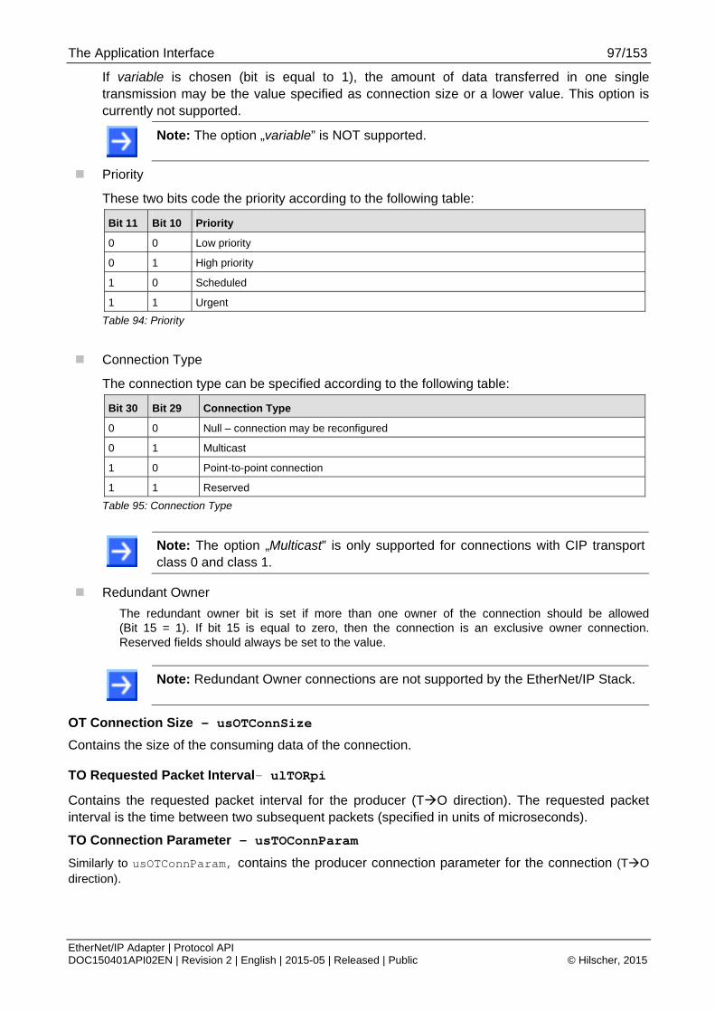
The Application Interface 97/153
EtherNet/IP Adapter | Protocol API DOC150401API02EN | Revision 2 | English | 2015-05 | Released | Public © Hilscher, 2015
If variable is chosen (bit is equal to 1), the amount of data transferred in one single transmission may be the value specified as connection size or a lower value. This option is currently not supported.
Note: The option „variable” is NOT supported.
Priority
These two bits code the priority according to the following table:
Bit 11 Bit 10 Priority
0 0 Low priority
0 1 High priority
1 0 Scheduled
1 1 Urgent
Table 94: Priority
Connection Type
The connection type can be specified according to the following table:
Bit 30 Bit 29 Connection Type
0 0 Null – connection may be reconfigured
0 1 Multicast
1 0 Point-to-point connection
1 1 Reserved
Table 95: Connection Type
Note: The option „Multicast” is only supported for connections with CIP transport class 0 and class 1.
Redundant Owner
The redundant owner bit is set if more than one owner of the connection should be allowed (Bit 15 = 1). If bit 15 is equal to zero, then the connection is an exclusive owner connection. Reserved fields should always be set to the value.
Note: Redundant Owner connections are not supported by the EtherNet/IP Stack.
OT Connection Size - usOTConnSize
Contains the size of the consuming data of the connection.
TO Requested Packet Interval- ulTORpi
Contains the requested packet interval for the producer (TO direction). The requested packet interval is the time between two subsequent packets (specified in units of microseconds).
TO Connection Parameter - usTOConnParam
Similarly to usOTConnParam, contains the producer connection parameter for the connection (TO direction).

The Application Interface 98/153
EtherNet/IP Adapter | Protocol API DOC150401API02EN | Revision 2 | English | 2015-05 | Released | Public © Hilscher, 2015
TO Connection Size - usTOConnSize
Contains the size of the producing data of the connection.
Production Inhibit Time - ulProInhib
Contains the production inhibit time
Extended State – ulExtendedState
The extended state has additional information about the connection. This value is only used when ulConnectionState is EIP_UNCONNECT
ulConnectionState = Numeric
Value
Meaning
If (ulConnectionState == EIP_UNCONNECT)
EIP_CONN_STATE_UNDEFINED 0 No extended state available
EIP_CONN_STATE_TIMEOUT 1 Connection closed by timeout
If (ulConnectionState == EIP_CONNECT)
EIP_CONN_STATE_UNDEFINED 0 No extended state available
Table 96: Priority
Figure 14 below displays a sequence diagram for the EIP_OBJECT_CONNECTION_IND/RES packet.
Figure 14: Sequence Diagram for the EIP_OBJECT_CONNECTION_IND/RES Packet for the Stack Packet Set

The Application Interface 99/153
EtherNet/IP Adapter | Protocol API DOC150401API02EN | Revision 2 | English | 2015-05 | Released | Public © Hilscher, 2015
Packet Structure Reference typedef struct EIP_OBJECT_CONNECTION_IND_Ttag { TLR_UINT32 ulConnectionState; uint16_t usNumExclusiveOwner; uint16_t usNumInputOnly; uint16_t usNumListenOnly; uint16_t usNumExplicitMessaging; uint8_t bConnType; uint8_t abReserved[3]; uint32_t ulClass; uint32_t ulInstance; uint32_t ulOTConnectionPoints; uint32_t ulTOConnectionPoints; uint16_t usConnSerialNum; uint16_t usVendorId; uint32_t ulOSerialNum; uint8_t bPriority; uint8_t bTimeOutTicks; uint8_t bTimeoutMultiple; uint8_t bTriggerType; uint32_t ulOTConnID; uint32_t ulTOConnID; uint32_t ulOTRpi; uint16_t usOTConnParam; uint16_t usOTConnSize; uint32_t ulTORpi; uint16_t usTOConnParam; uint16_t usTOConnSize; uint32_t ulProInhib; TLR_UINT32 ulExtendedState; } EIP_OBJECT_CONNECTION_IND_T; #define EIP_OBJECT_CONNECTION_IND_SIZE \ sizeof(EIP_OBJECT_CONNECTION_IND_T) typedef struct EIP_OBJECT_PACKET_CONNECTION_IND_Ttag { TLR_PACKET_HEADER_T tHead; EIP_OBJECT_CONNECTION_IND_T tData; } EIP_OBJECT_PACKET_CONNECTION_IND_T;
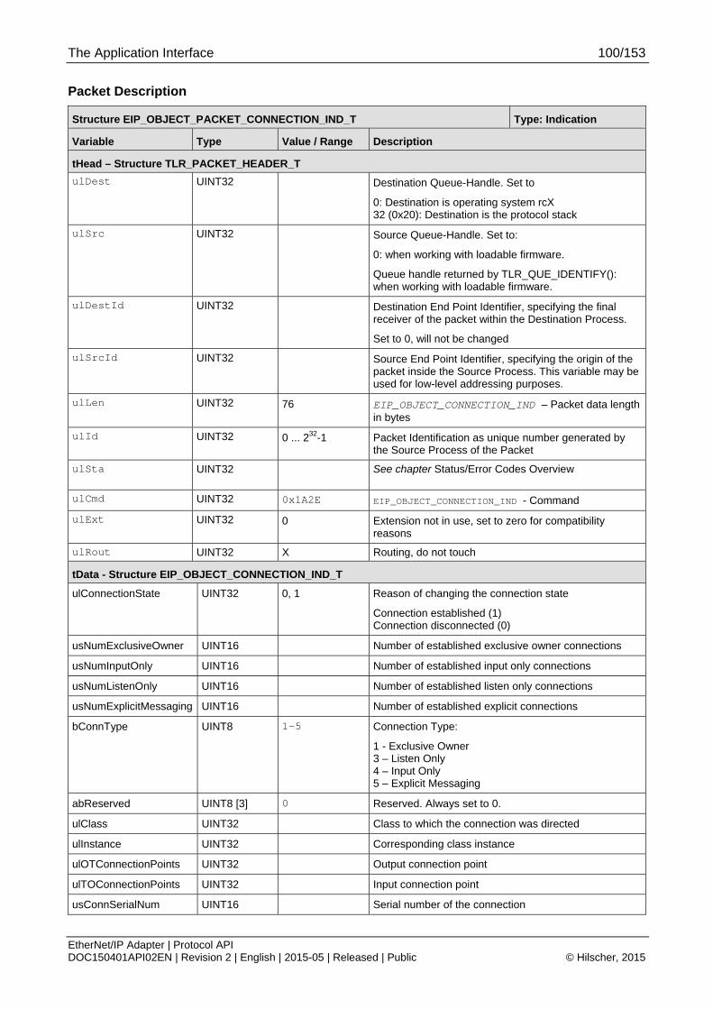
The Application Interface 100/153
EtherNet/IP Adapter | Protocol API DOC150401API02EN | Revision 2 | English | 2015-05 | Released | Public © Hilscher, 2015
Packet Description
Structure EIP_OBJECT_PACKET_CONNECTION_IND_T Type: Indication
Variable Type Value / Range Description
tHead – Structure TLR_PACKET_HEADER_T
ulDest UINT32 Destination Queue-Handle. Set to
0: Destination is operating system rcX 32 (0x20): Destination is the protocol stack
ulSrc UINT32 Source Queue-Handle. Set to:
0: when working with loadable firmware.
Queue handle returned by TLR_QUE_IDENTIFY(): when working with loadable firmware.
ulDestId UINT32 Destination End Point Identifier, specifying the final receiver of the packet within the Destination Process.
Set to 0, will not be changed
ulSrcId UINT32 Source End Point Identifier, specifying the origin of the packet inside the Source Process. This variable may be used for low-level addressing purposes.
ulLen UINT32 76 EIP_OBJECT_CONNECTION_IND – Packet data length in bytes
ulId UINT32 0 ... 232-1 Packet Identification as unique number generated by the Source Process of the Packet
ulSta UINT32 See chapter Status/Error Codes Overview
ulCmd UINT32 0x1A2E EIP_OBJECT_CONNECTION_IND - Command
ulExt UINT32 0 Extension not in use, set to zero for compatibility reasons
ulRout UINT32 X Routing, do not touch
tData - Structure EIP_OBJECT_CONNECTION_IND_T
ulConnectionState UINT32 0, 1 Reason of changing the connection state
Connection established (1) Connection disconnected (0)
usNumExclusiveOwner UINT16 Number of established exclusive owner connections
usNumInputOnly UINT16 Number of established input only connections
usNumListenOnly UINT16 Number of established listen only connections
usNumExplicitMessaging UINT16 Number of established explicit connections
bConnType UINT8 1-5 Connection Type:
1 - Exclusive Owner 3 – Listen Only 4 – Input Only 5 – Explicit Messaging
abReserved UINT8 [3] 0 Reserved. Always set to 0.
ulClass UINT32 Class to which the connection was directed
ulInstance UINT32 Corresponding class instance
ulOTConnectionPoints UINT32 Output connection point
ulTOConnectionPoints UINT32 Input connection point
usConnSerialNum UINT16 Serial number of the connection

The Application Interface 101/153
EtherNet/IP Adapter | Protocol API DOC150401API02EN | Revision 2 | English | 2015-05 | Released | Public © Hilscher, 2015
Structure EIP_OBJECT_PACKET_CONNECTION_IND_T Type: Indication
usVendorId UINT16 Originator vendor id
ulOSerialNum UINT32 Originator serial number
bPriority UINT8 Priority/Tick Time
bTimeOutTicks UINT8 Message timeout
bTimeoutMultiple UINT8 Time out multiplier
bTriggerType UINT8 Class/Trigger type
ulOTConnID UINT32 O->T Connection ID
ulTOConnID UINT32 T->O ConnectionID
ulOTRpi UINT32 O->T requested packet interval
usOTConnParam UINT16 O->T Connection parameter
usOTConnSize UINT16 O->T data size
ulTORpi UINT32 T->O requested packet interval
usTOConnParam UINT16 T->O Connection parameter
usTOConnSize UINT16 T->O data size
ulProInhib UINT32 Producer inhibit time
ulExtendedState UINT32 0: No extended status 1: Connection timeout
Table 97: EIP_OBJECT_CONNECTION_IND – Indication of Connection

The Application Interface 102/153
EtherNet/IP Adapter | Protocol API DOC150401API02EN | Revision 2 | English | 2015-05 | Released | Public © Hilscher, 2015
Packet Structure Reference struct EIP_OBJECT_PACKET_CONNECTION_RES_Ttag { TLR_PACKET_HEADER_T tHead; };
Packet Description
Structure EIP_OBJECT_PACKET_CONNECTION_RES_T Type: Response
Variable Type Value / Range Description
tHead – Structure TLR_PACKET_HEADER_T
ulDest UINT32 See rules in section 3.2.1
Destination Queue Handle
ulSrc UINT32 See rules in section 3.2.1
Source Queue Handle
ulDestId UINT32 See rules in section 3.2.1
Destination Queue Reference
ulSrcId UINT32 See rules in section 3.2.1
Source Queue Reference
ulLen UINT32 0 Packet Data Length (In Bytes)
ulId UINT32 0 ... 232-1 Packet Identification As Unique Number
ulSta UINT32 See chapter Status/Error Codes Overview
ulCmd UINT32 0x00001A2F Command / Response
ulExt UINT32 Reserved
ulRout UINT32 Routing Information
Table 5: EIP_OBJECT_CONNECTION_RES – Response to indication of Connection
The Application Interface 103/153
EtherNet/IP Adapter | Protocol API DOC150401API02EN | Revision 2 | English | 2015-05 | Released | Public © Hilscher, 2015
4.2.3 Indication of acyclic Data Transfer
This packet indicates an acyclic service coming from the network. It will only be received if:
an additional object class has been registered using the command EIP_OBJECT_MR_REGISTER_REQ/CNF (see section 4.1.4 on page 64 of this document)
or a service has been registered for an existing object using EIP_OBJECT_REGISTER_SERVICE_REQ/CNF (see section 4.1.7 on page 78 of this document)
It delivers the following parameters:
the OT connection ID of the class 3 connection, in case the service request is bound to a class 3 connection (connected)
a CIP Service Code
the CIP Object Class ID
the CIP Instance number
the CIP Attribute number
an array containing unstructured data (depending on the service code)
the sequence count in case this service was sent over a class 3 connection (see ulSrcId of packet header)
The parameters service code, class ID, instance and attribute correspond to the normal CIP Addressing. These fields are used for the most common services that use the addressing format “Service Class Instance Attribute”. In case the service uses another format, the path information is put into the data part (abData[]) of this packet.
The data segment abData[] may not be present for services that do not need data sent along with the request (e.g. Get services). The ulLen field of the packet header can be evaluated to determine whether there is data available.
service_data_size = tHead.ulLen - EIP_OBJECT_CL3_SERVICE_IND_SIZE
The parameter ulService holds the requested CIP service that shall be applied to the object instance selected by the variables ulObject and ulInstance of the indication packet.
CIP services are divided into different address ranges. The subsequent Table 98: Specified Ranges of numeric Values of Service Codes (Variable ulService) gives an overview. This table is taken from the CIP specification (“Volume 1 Common Industrial Protocol Specification Chapter 4, Table 4-9.6”, see reference [3]).

The Application Interface 104/153
EtherNet/IP Adapter | Protocol API DOC150401API02EN | Revision 2 | English | 2015-05 | Released | Public © Hilscher, 2015
Range of numeric value
of service code
(variable ulService)
Meaning
0x00-0x31 Open. The services associated with this range of service codes are referred to as Common Services. These are defined in Appendix A of the CIP Networks Library, Volume 1 (reference #3).
0x32-0x4A Range for service codes for vendor specific services
0x4B-0x63 Range for service codes for object class specific services
0x64-0x7F Reserved by ODVA for future use
0x80-0xFF Reserved for use as Reply Service Code (see Message Router Response Format in Chapter 2 of reference [4])
0x0100-0xFFFF Hilscher specific services to manage objects from application side.
Table 98: Specified Ranges of numeric Values of Service Codes (Variable ulService)
Note: Not every service is available on every object.
If you use Class IDs that are in the Vendor Specific range, use need to define by yourself what services and attributes are supported by this object class.
If you use Class IDs that are not in the Vendor Specific range, the CIP specification describes all required and optional services and attributes the class supports.
Depending on this the host application must implement the handling of incoming services.
Table 99: Service Codes for the Common Services according to the CIP specification lists the service codes for the Common Services. This table is taken from the CIP specification (“Volume 1 Common Industrial Protocol Specification Chapter 5, Table 5-1.1”, see reference [3]).
Service code (numeric value of ulService)
Service to be executed
00 Reserved
01 Get_Attributes_All
02 Set_Attributes_All
03 Get_Attribute_List
04 Set_Attribute_List
05 Reset
06 Start
07 Stop
08 Create
09 Delete
0A Multiple_Service_Packet
0B Reserved for future use
0D Apply_Attributes
0E Get_Attribute_Single

The Application Interface 105/153
EtherNet/IP Adapter | Protocol API DOC150401API02EN | Revision 2 | English | 2015-05 | Released | Public © Hilscher, 2015
Service code (numeric value of ulService)
Service to be executed
0F Reserved for future use
10 Set_Attribute_Single
11 Find_Next_Object_Instance
12-13 Reserved for future use
14 Error Response (used by DevNet only)
15 Restore
16 Save
17 No Operation (NOP)
18 Get_Member
19 Set_Member
1A Insert_Member
1B Remove_Member
1C GroupSync
1D-31 Reserved for additional Common Services
Table 99: Service Codes for the Common Services according to the CIP specification
Depending on what services, instances and attributes are supported by the addressed object, the host application must answer the service with either success or with an appropriate error code.
Therefore, the response packet holds two error fields: ulGRC and ulERC
The Generic Error Code (ulGRC) can be used to indicate whether the service request could be processed successfully or not. A list of all possible codes is provided in section 5.2“General EtherNet/IP Error Codes” of this document.

The Application Interface 106/153
EtherNet/IP Adapter | Protocol API DOC150401API02EN | Revision 2 | English | 2015-05 | Released | Public © Hilscher, 2015
The most common General Error Codes are:
General Status Code
(specified hexadecimally)
Status Name Description
00 Success The service has successfully been performed by the specified object.
05 Path destination unknown
The path references an unknown object class, instance or structure element causing the abort of path processing.
08 Service not supported
The requested service has not been implemented or has not been defined for this object class or instance.
09 Invalid attribute value Detection of invalid attribute data
0A Attribute list error An attribute in the Get_Attribute_List or Set_Attribute_List response has a status not equal to 0.
0C Object state conflict The object is not able to perform the requested service in the current mode or state
0E Attribute not settable Attempt to change a non-modifiable attribute.
10 Device state conflict The current mode or state of the device prevents the execution of the requested service.
13 Not enough data The service did not supply all required data to perform the specified operation.
14 Attribute not supported
An unsupported attribute has been specified in the request
15 Too much data More data than was expected were supplied by the service.
1F Vendor specific error A vendor specific error has occurred. This error should only occur when none of the other general error codes can correctly be applied.
20 Invalid parameter A parameter which was associated with the request was invalid. The parameter does not meet the requirements of the CIP specification and/or the requirements defined in the specification of an application object.
Table 100: Most common General Status Codes
The Extended Error Code (ERC) can be used to describe the occurred error having already been classified by the generic error code in more detail.
If the service will be answered with success, additional data can be sent with the reply in the abData field. The byte size of the data must be added to the basic packet length (EIP_OBJECT_CL3_SERVICE_RES_SIZE) in the ulLen field of the packet header.
Figure 9 below displays a sequence diagram for the EIP_OBJECT_CL3_SERVICE_IND/RES packet in case the host application uses the Extended or Stack Packet Set (see 3.2 “Configuration Using the Packet API”).
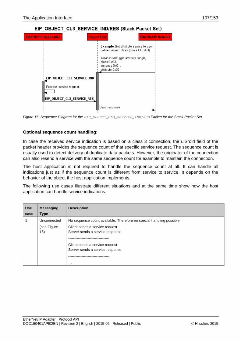
The Application Interface 107/153
EtherNet/IP Adapter | Protocol API DOC150401API02EN | Revision 2 | English | 2015-05 | Released | Public © Hilscher, 2015
Figure 15: Sequence Diagram for the EIP_OBJECT_CL3_SERVICE_IND/RES Packet for the Stack Packet Set
Optional sequence count handling:
In case the received service indication is based on a class 3 connection, the ulSrcId field of the packet header provides the sequence count of that specific service request. The sequence count is usually used to detect delivery of duplicate data packets. However, the originator of the connection can also resend a service with the same sequence count for example to maintain the connection.
The host application is not required to handle the sequence count at all. It can handle all indications just as if the sequence count is different from service to service. It depends on the behavior of the object the host application implements.
The following use cases illustrate different situations and at the same time show how the host application can handle service indications.
Use
case
Messaging
Type
Description
1 Unconnected
(see Figure 16)
No sequence count available. Therefore no special handling possible
Client sends a service request Server sends a service response
----------------------------------
Client sends a service request Server sends a service response
----------------------------------
…
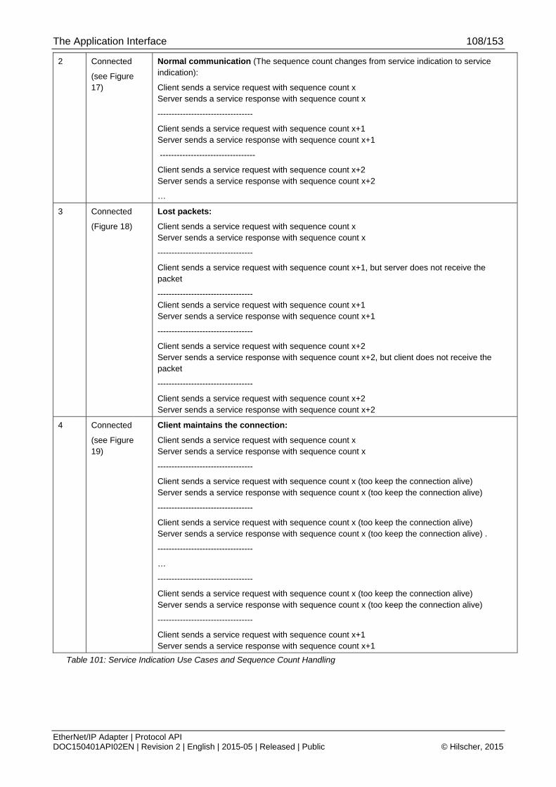
The Application Interface 108/153
EtherNet/IP Adapter | Protocol API DOC150401API02EN | Revision 2 | English | 2015-05 | Released | Public © Hilscher, 2015
2 Connected
(see Figure 17)
Normal communication (The sequence count changes from service indication to service indication):
Client sends a service request with sequence count x Server sends a service response with sequence count x
----------------------------------
Client sends a service request with sequence count x+1 Server sends a service response with sequence count x+1
----------------------------------
Client sends a service request with sequence count x+2 Server sends a service response with sequence count x+2
…
3 Connected
(Figure 18)
Lost packets:
Client sends a service request with sequence count x Server sends a service response with sequence count x
----------------------------------
Client sends a service request with sequence count x+1, but server does not receive the packet
---------------------------------- Client sends a service request with sequence count x+1 Server sends a service response with sequence count x+1
----------------------------------
Client sends a service request with sequence count x+2 Server sends a service response with sequence count x+2, but client does not receive the packet
----------------------------------
Client sends a service request with sequence count x+2 Server sends a service response with sequence count x+2
4 Connected
(see Figure 19)
Client maintains the connection:
Client sends a service request with sequence count x Server sends a service response with sequence count x
----------------------------------
Client sends a service request with sequence count x (too keep the connection alive) Server sends a service response with sequence count x (too keep the connection alive)
----------------------------------
Client sends a service request with sequence count x (too keep the connection alive) Server sends a service response with sequence count x (too keep the connection alive) .
----------------------------------
…
----------------------------------
Client sends a service request with sequence count x (too keep the connection alive) Server sends a service response with sequence count x (too keep the connection alive)
----------------------------------
Client sends a service request with sequence count x+1 Server sends a service response with sequence count x+1
Table 101: Service Indication Use Cases and Sequence Count Handling

The Application Interface 109/153
EtherNet/IP Adapter | Protocol API DOC150401API02EN | Revision 2 | English | 2015-05 | Released | Public © Hilscher, 2015
Figure 16: Sequence Diagram for the EIP_OBJECT_CL3_SERVICE_IND/RES (Sequence Count Handling– Use case 1)

The Application Interface 110/153
EtherNet/IP Adapter | Protocol API DOC150401API02EN | Revision 2 | English | 2015-05 | Released | Public © Hilscher, 2015
Figure 17: Sequence Diagram for the EIP_OBJECT_CL3_SERVICE_IND/RES (Sequence Count Handling– Use case 2)

The Application Interface 111/153
EtherNet/IP Adapter | Protocol API DOC150401API02EN | Revision 2 | English | 2015-05 | Released | Public © Hilscher, 2015
Figure 18: Sequence Diagram for the EIP_OBJECT_CL3_SERVICE_IND/RES (Sequence Count Handling– Use case 3)

The Application Interface 112/153
EtherNet/IP Adapter | Protocol API DOC150401API02EN | Revision 2 | English | 2015-05 | Released | Public © Hilscher, 2015
Figure 19: Sequence Diagram for the EIP_OBJECT_CL3_SERVICE_IND/RES (Sequence Count Handling– Use case 4)

The Application Interface 113/153
EtherNet/IP Adapter | Protocol API DOC150401API02EN | Revision 2 | English | 2015-05 | Released | Public © Hilscher, 2015
Packet Structure Reference typedef struct EIP_OBJECT_CL3_SERVICE_IND_Ttag { TLR_UINT32 ulConnectionId; /*!< Connection Handle */ TLR_UINT32 ulService; TLR_UINT32 ulObject; TLR_UINT32 ulInstance; TLR_UINT32 ulAttribute; TLR_UINT8 abData[1]; } EIP_OBJECT_CL3_SERVICE_IND_T; typedef struct EIP_OBJECT_PACKET_CL3_SERVICE_IND_Ttag { TLR_PACKET_HEADER_T tHead; EIP_OBJECT_CL3_SERVICE_IND_T tData; } EIP_OBJECT_PACKET_CL3_SERVICE_IND_T; #define EIP_OBJECT_CL3_SERVICE_IND_SIZE (sizeof(EIP_OBJECT_CL3_SERVICE_IND_T)-1)

The Application Interface 114/153
EtherNet/IP Adapter | Protocol API DOC150401API02EN | Revision 2 | English | 2015-05 | Released | Public © Hilscher, 2015
Packet Description
Structure EIP_OBJECT_PACKET_CL3_SERVICE_IND_T Type: Indication
Variable Type Value / Range Description
tHead – Structure TLR_PACKET_HEADER_T
ulDest UINT32 Destination Queue-Handle. Set to
0: Destination is operating system rcX
32 (0x20): Destination is the protocol stack
ulSrc UINT32 Source Queue-Handle. Set to:
0: when working with loadable firmware.
Queue handle returned by TLR_QUE_IDENTIFY(): when working with loadable firmware.
ulDestId UINT32 Destination End Point Identifier, specifying the final receiver of the packet within the Destination Process.
Set to 0, will not be changed
ulSrcId UINT32 Holds the sequence count of the service request in case the service is based on a class 3 connection (tData.ulConnectionId != 0).
ulSrcId is always 0 for unconnected service request.
(see sequence diagrams in Figure 16, Figure 17, Figure 18 and Figure 19)
ulLen UINT32 20 + n Packet Data Length (In Bytes)
n = Length of Service Data Area
ulId UINT32 0 ... 232-1 Packet Identification As Unique Number
ulSta UINT32 See Packet Structure Reference
ulCmd UINT32 0x1A3E EIP_OBJECT_CL3_SERVICE_IND - Command / Response
ulExt UINT32 Reserved
ulRout UINT32 Routing Information
tData - Structure EIP_OBJECT_CL3_SERVICE_IND_T
ulConnectionId UINT32 0 ... 232-1 Uncial number of the request
ulService UINT32 1-0xFFFF CIP Service Code
ulObject UINT32 1-0xFFFF CIP Class ID
ulInstance UINT32 1-0xFFFF CIP Instance Number
ulAttribute UINT32 0-0xFFFF CIP Attribute Number
The attribute number is 0, if the service does not address a specific attribute but the whole instance.
abData[] UINT8[n] n bytes of service data (depending on service)
This may also contain path information for instance in case that the service does not address an object with the format Class / Instance / Attribute.
Table 102: EIP_OBJECT_CL3_SERVICE_IND - Indication of acyclic Data Transfer

The Application Interface 115/153
EtherNet/IP Adapter | Protocol API DOC150401API02EN | Revision 2 | English | 2015-05 | Released | Public © Hilscher, 2015
Packet Structure Reference typedef struct EIP_OBJECT_CL3_SERVICE_RES_Ttag { TLR_UINT32 ulConnectionId; /*!< Connection Handle */ TLR_UINT32 ulService; TLR_UINT32 ulObject; TLR_UINT32 ulInstance; TLR_UINT32 ulAttribute; TLR_UINT32 ulGRC; /*!< Generic Error Code */ TLR_UINT32 ulERC; /*!< Extended Error Code */ TLR_UINT8 abData[1]; }EIP_OBJECT_CL3_SERVICE_RES_T; typedef struct EIP_OBJECT_PACKET_CL3_SERVICE_RES_Ttag { TLR_PACKET_HEADER_T tHead; EIP_OBJECT_CL3_SERVICE_RES_T tData; } EIP_OBJECT_PACKET_CL3_SERVICE_RES_T; #define EIP_OBJECT_CL3_SERVICE_RES_SIZE (sizeof(EIP_OBJECT_CL3_SERVICE_RES_T)-1)
Packet Description
Structure EIP_OBJECT_PACKET_CL3_SERVICE_RES_T Type: Response
Variable Type Value / Range Description
tHead – Structure TLR_PACKET_HEADER_T
ulDest UINT32 See rules in section 3.2.1
Destination Queue Handle
ulSrc UINT32 See rules in section 3.2.1
Source Queue Handle
ulDestId UINT32 See rules in section 3.2.1
Destination End Point Identifier, specifying the final receiver of the packet within the Destination Process.
ulSrcId UINT32 See rules in section 3.2.1
Source End Point Identifier, specifying the origin of the packet inside the Source Process
ulLen UINT32 28 + n Packet Data Length (In Bytes) where n = Length of Service Data Area
ulId UINT32 0 ... 232-1 Packet Identification As Unique Number
ulSta UINT32 See chapter Status/Error Codes Overview
ulCmd UINT32 0x00001A3F EIP_OBJECT_CL3_SERVICE_RES - Command / Response
ulExt UINT32 Reserved
ulRout UINT32 Routing Information
tData - Structure EIP_OBJECT_CL3_SERVICE_RES_T
ulConnectionId UINT32 0 ... 232-1 Unique Id from the indication packet
ulService UINT32 1-0xFFFF CIP Service Code from the indication packet
ulObject UINT32 1-0xFFFF CIP Object from the indication packet
ulInstance UINT32 1-0xFFFF CIP Instance from the indication packet
ulAttribute UINT32 0-0xFFFF CIP Attribute from the indication packet
ulGRC UINT32 Generic Error Code
ulERC UINT32 Extended Error Code
abData[] Array of UINT8 n bytes of service data (depending on service)
Table 103: EIP_OBJECT_CL3_SERVICE_RES – Response to Indication of acyclic Data Transfer

The Application Interface 116/153
EtherNet/IP Adapter | Protocol API DOC150401API02EN | Revision 2 | English | 2015-05 | Released | Public © Hilscher, 2015
4.2.4 CIP Object Change Indication
This indication will be received by the host application when a CIP object attribute is changed/set by service from the network. Basically, changes to object attributes that are non-volatile are indicated.
For detailed information about how to handle this indication see section 3.3 “Example Configuration Process”
For configuration examples please refer to the example code SetConfigExample and ExtendedConfigExample.
Handling of Configuration Data Changes”.
Figure 20 below displays a sequence diagram for the EIP_OBJECT_CIP_OBJECT_CHANGE_IND/RES packet in case the host application uses the Basic, Extended or Stack Packet Set (see 3.2 “Configuration Using the Packet API”).
Figure 20: Sequence Diagram for the EIP_OBJECT_CIP_OBJECT_CHANGE_IND/RES Packet for the Stack Packet Set
Packet Structure Reference typedef struct EIP_OBJECT_CIP_OBJECT_CHANGE_IND_Ttag { TLR_UINT32 ulInfoFlags; /*!< Information flags */ TLR_UINT32 ulService; /*!< CIP service code */ TLR_UINT32 ulClass; /*!< CIP class ID */ TLR_UINT32 ulInstance; /*!< CIP instance number */ TLR_UINT32 ulAttribute; /*!< CIP attribute number */ TLR_UINT8 abData[EIP_OBJECT_MAX_PACKET_LEN]; /*!< Service Data */ } EIP_OBJECT_CIP_OBJECT_CHANGE_IND_T; typedef struct EIP_OBJECT_PACKET_CIP_OBJECT_CHANGE_IND_Ttag { TLR_PACKET_HEADER_T tHead; EIP_OBJECT_CIP_OBJECT_CHANGE_IND_T tData; } EIP_OBJECT_PACKET_CIP_OBJECT_CHANGE_IND_T; #define EIP_OBJECT_CIP_OBJECT_CHANGE_IND_SIZE (sizeof(EIP_OBJECT_CIP_OBJECT_CHANGE_IND_T) - EIP_OBJECT_MAX_PACKET_LEN)

The Application Interface 117/153
EtherNet/IP Adapter | Protocol API DOC150401API02EN | Revision 2 | English | 2015-05 | Released | Public © Hilscher, 2015
Packet Description
structure EIP_OBJECT_PACKET_CIP_OBJECT_CHANGE_IND_T
Type: Indication
Area Variable Type Value / Range Description
structure TLR_PACKET_HEADER_T
ulDest UINT32 Destination Queue-Handle
ulSrc UINT32 Source Queue-Handle
ulDestId UINT32 Destination End Point Identifier, specifying the final receiver of the packet within the Destination Process. Set to 0 for the Initialization Packet
ulSrcId UINT32 Source End Point Identifier, specifying the origin of the packet inside the Source Process
ulLen UINT32 20+n Packet Data Length in bytes n = Number of bytes in abData[]
ulId UINT32 0 ... 232-1 Packet Identification as unique number generated by the Source Process of the Packet
ulSta UINT32 See chapter Status/Error Codes Overview
ulCmd UINT32 0x1AFA EIP_OBJECT_CIP_OBJECT_CHANGE_IND - Command
ulExt UINT32 0 Extension not in use, set to zero for compatibility reasons
tHead
ulRout UINT32 x Routing, do not touch
structure EIP_OBJECT_CIP_OBJECT_CHANGE_IND_T
ulInfoFlags UINT32 reserved
ulService UINT32 0x10 CIP service code
Currently only the SetAttributeSingle service is used in this indication.
ulClass UINT32 CIP class ID
ulInstance UINT32 CIP instance number
ulAttribute UINT32 CIP attribute number
tData
abData[] UINT8 Attribute Data
Number of bytes n provided in abData =
tHead.ulLen - EIP_OBJECT_CIP_OBJECT_CHANGE_IND_SIZE
Table 104: EIP_OBJECT_CIP_OBJECT_CHANGE_IND – CIP Object Change Indication
Packet Structure Reference typedef struct EIP_OBJECT_PACKET_CIP_OBJECT_CHANGE_RES_Ttag { TLR_PACKET_HEADER_T tHead; } EIP_OBJECT_PACKET_CIP_OBJECT_CHANGE_RES_T; #define EIP_OBJECT_CIP_OBJECT_CHANGE_RES_SIZE 0
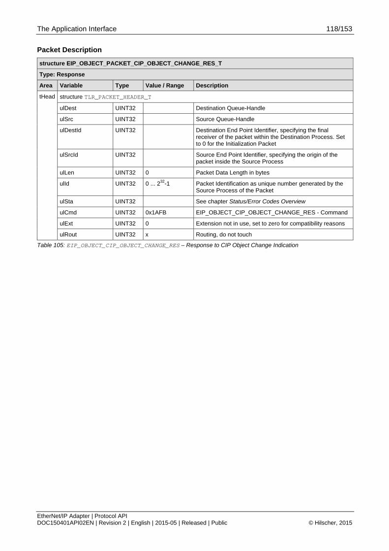
The Application Interface 118/153
EtherNet/IP Adapter | Protocol API DOC150401API02EN | Revision 2 | English | 2015-05 | Released | Public © Hilscher, 2015
Packet Description
structure EIP_OBJECT_PACKET_CIP_OBJECT_CHANGE_RES_T
Type: Response
Area Variable Type Value / Range Description
structure TLR_PACKET_HEADER_T
ulDest UINT32 Destination Queue-Handle
ulSrc UINT32 Source Queue-Handle
ulDestId UINT32 Destination End Point Identifier, specifying the final receiver of the packet within the Destination Process. Set to 0 for the Initialization Packet
ulSrcId UINT32 Source End Point Identifier, specifying the origin of the packet inside the Source Process
ulLen UINT32 0 Packet Data Length in bytes
ulId UINT32 0 ... 232-1 Packet Identification as unique number generated by the Source Process of the Packet
ulSta UINT32 See chapter Status/Error Codes Overview
ulCmd UINT32 0x1AFB EIP_OBJECT_CIP_OBJECT_CHANGE_RES - Command
ulExt UINT32 0 Extension not in use, set to zero for compatibility reasons
tHead
ulRout UINT32 x Routing, do not touch
Table 105: EIP_OBJECT_CIP_OBJECT_CHANGE_RES – Response to CIP Object Change Indication

The Application Interface 119/153
EtherNet/IP Adapter | Protocol API DOC150401API02EN | Revision 2 | English | 2015-05 | Released | Public © Hilscher, 2015
4.2.5 Link Status Change
This indication informs the application about the current Link status. This is informative for the application. Information from any earlier received Link Status Changed Indication is invalid at this point of time.
Note:
This indication is also sent directly after the host application has registered at the EtherNet/IP Stack (RCX_REGISTER_APP_REQ – 0x2F10).
Packet Structure Reference typedef struct RCX_LINK_STATUS_Ttag { TLR_UINT32 ulPort; /*!< Port number\n\n \valueRange \n 0: Port 1 \n 1: Port 2 */ TLR_BOOLEAN fIsFullDuplex; /*!< Duplex mode\n\n \valueRange \n 0: Half duplex \n 1: Full Duplex */ TLR_BOOLEAN fIsLinkUp; /*!< Link status\n\n \valueRange \n 0: Link is down \n 1: Link is up */ TLR_UINT32 ulSpeed; /*!< Port speed\n\n \valueRange \n 0: (No link) \n 10: 10MBit \n 100: 100MBit \n */ } RCX_LINK_STATUS_T; typedef struct RCX_LINK_STATUS_CHANGE_IND_DATA_Ttag { RCX_LINK_STATUS_T atLinkData[2]; /*!< Link status data */ } RCX_LINK_STATUS_CHANGE_IND_DATA_T; typedef struct RCX_LINK_STATUS_CHANGE_IND_Ttag { TLR_PACKET_HEADER_T tHead; RCX_LINK_STATUS_CHANGE_IND_DATA_T tData; } RCX_LINK_STATUS_CHANGE_IND_T; #define RCX_LINK_STATUS_CHANGE_IND_SIZE (sizeof(RCX_LINK_STATUS_CHANGE_IND_DATA_T))
Packet Description
Structure RCX_LINK_STATUS_CHANGE_IND_T Type: Indication
Area Variable Type Value / Range
Description
structure TLR_PACKET_HEADER_T
ulDest UINT32 Destination queue handle of application task process queue
ulSrc UINT32 Source queue handle of AP-task process queue
ulDestId UINT32 0 Destination End Point Identifier not in use, set to zero for compatibility reasons
Head
ulSrcId UINT32 0 ... 232 -1 Source End Point Identifier, specifying the origin of the packet inside the Source Process.
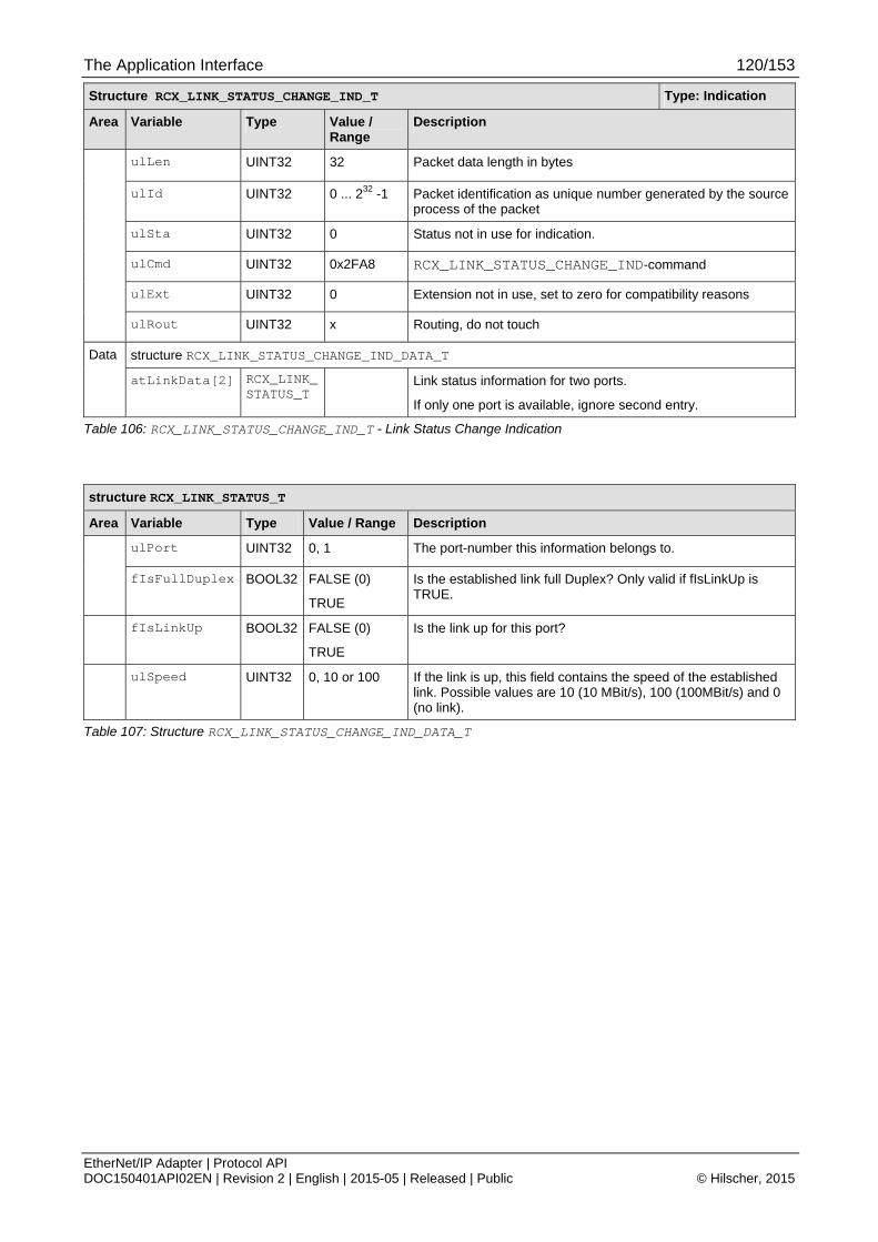
The Application Interface 120/153
EtherNet/IP Adapter | Protocol API DOC150401API02EN | Revision 2 | English | 2015-05 | Released | Public © Hilscher, 2015
Structure RCX_LINK_STATUS_CHANGE_IND_T Type: Indication
Area Variable Type Value / Range
Description
ulLen UINT32 32 Packet data length in bytes
ulId UINT32 0 ... 232 -1 Packet identification as unique number generated by the source process of the packet
ulSta UINT32 0 Status not in use for indication.
ulCmd UINT32 0x2FA8 RCX_LINK_STATUS_CHANGE_IND-command
ulExt UINT32 0 Extension not in use, set to zero for compatibility reasons
ulRout UINT32 x Routing, do not touch
structure RCX_LINK_STATUS_CHANGE_IND_DATA_T Data
atLinkData[2] RCX_LINK_STATUS_T
Link status information for two ports.
If only one port is available, ignore second entry.
Table 106: RCX_LINK_STATUS_CHANGE_IND_T - Link Status Change Indication
structure RCX_LINK_STATUS_T
Area Variable Type Value / Range Description
ulPort UINT32 0, 1 The port-number this information belongs to.
fIsFullDuplex BOOL32 FALSE (0)
TRUE
Is the established link full Duplex? Only valid if fIsLinkUp is TRUE.
fIsLinkUp BOOL32 FALSE (0)
TRUE
Is the link up for this port?
ulSpeed UINT32 0, 10 or 100 If the link is up, this field contains the speed of the established link. Possible values are 10 (10 MBit/s), 100 (100MBit/s) and 0 (no link).
Table 107: Structure RCX_LINK_STATUS_CHANGE_IND_DATA_T

The Application Interface 121/153
EtherNet/IP Adapter | Protocol API DOC150401API02EN | Revision 2 | English | 2015-05 | Released | Public © Hilscher, 2015
Packet Structure Reference typedef struct RCX_LINK_STATUS_CHANGE_RES_Ttag { TLR_PACKET_HEADER_T tHead; } RCX_LINK_STATUS_CHANGE_RES_T; #define RCX_LINK_STATUS_CHANGE_RES_SIZE (0)
Packet Description
Structure RCX_LINK_STATUS_CHANGE_RES_T Type: Response
Variable Type Value / Range Description
tHead – Structure TLR_PACKET_HEADER_T
ulDest UINT32 Destination queue handle of application task process queue
ulSrc UINT32 Source Queue-Handle
ulDestId UINT32 0 Destination End Point Identifier
ulSrcId UINT32 0 ... 232 -1 Source End Point Identifier, specifying the origin of the packet inside the Source Process.
ulLen UINT32 0 Packet data length in bytes. Depends on number of parameters
ulId UINT32 0 ... 232 -1 Packet identification as unique number generated by the source process of the packet
ulSta UINT32 Status not used for request.
ulCmd UINT32 0x2FA9 RCX_LINK_STATUS_CHANGE_RES – Command
ulExt UINT32 0 Extension not in use, set to zero for compatibility reasons
ulRout UINT32 x Routing, do not touch
Table 108: RCX_LINK_STATUS_CHANGE_RES_T - Link Status Change Response
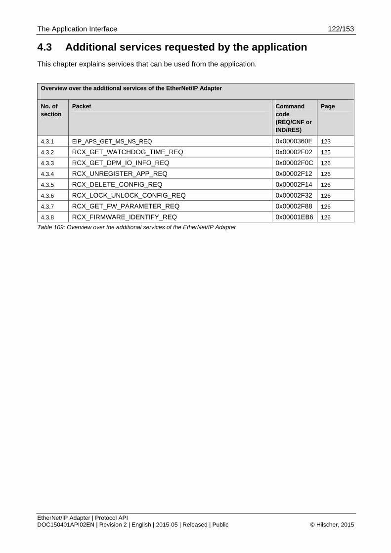
The Application Interface 122/153
EtherNet/IP Adapter | Protocol API DOC150401API02EN | Revision 2 | English | 2015-05 | Released | Public © Hilscher, 2015
4.3 Additional services requested by the application
This chapter explains services that can be used from the application.
Overview over the additional services of the EtherNet/IP Adapter
No. of section
Packet Command code (REQ/CNF or IND/RES)
Page
4.3.1 EIP_APS_GET_MS_NS_REQ 0x0000360E 123
4.3.2 RCX_GET_WATCHDOG_TIME_REQ 0x00002F02 125
4.3.3 RCX_GET_DPM_IO_INFO_REQ 0x00002F0C 126
4.3.4 RCX_UNREGISTER_APP_REQ 0x00002F12 126
4.3.5 RCX_DELETE_CONFIG_REQ 0x00002F14 126
4.3.6 RCX_LOCK_UNLOCK_CONFIG_REQ 0x00002F32 126
4.3.7 RCX_GET_FW_PARAMETER_REQ 0x00002F88 126
4.3.8 RCX_FIRMWARE_IDENTIFY_REQ 0x00001EB6 126
Table 109: Overview over the additional services of the EtherNet/IP Adapter

The Application Interface 123/153
EtherNet/IP Adapter | Protocol API DOC150401API02EN | Revision 2 | English | 2015-05 | Released | Public © Hilscher, 2015
4.3.1 Get Module Status/ Network Status
This packet can be used by the EtherNet/IP Adapter Application in order to obtain information about the current module and network status for further evaluation.
Table 114 on page 132 lists all possible values of the Module Status (Parameter ulModuleStatus of the confirmation packet) and their meanings.
Similarly, Table 115 on page 133 lists all possible values of the Network Status (Parameter ulNetworkStatus of the confirmation packet) and their meanings.
Figure 21 below displays a sequence diagram for the EIP_APS_GET_MS_NS_REQ/CNF packet:
Figure 21: Sequence Diagram for the EIP_APS_GET_MS_NS_REQ/CNF Packet
Packet Structure Reference #define EIP_APS_GET_MS_NS_REQ_SIZE 0 typedef struct EIP_APS_PACKET_GET_MS_NS_REQ_Ttag { TLR_PACKET_HEADER_T tHead; } EIP_APS_PACKET_GET_MS_NS_REQ_T;

The Application Interface 124/153
EtherNet/IP Adapter | Protocol API DOC150401API02EN | Revision 2 | English | 2015-05 | Released | Public © Hilscher, 2015
Packet Description
structure EIP_APS_PACKET_GET_MS_NS_REQ_T
Type: Request
Area Variable Type Value / Range Description
structure TLR_PACKET_HEADER_T
ulDest UINT32 0x20/ DPMINTF_QUE
Destination Queue-Handle
ulSrc UINT32 0 ... 232-1 Source Queue-Handle
ulDestId UINT32 See rules in section 3.2.1
Destination End Point Identifier, specifying the final receiver of the packet within the Destination Process. Set to 0 for the Initialization Packet
ulSrcId UINT32 See rules in section 3.2.1
Source End Point Identifier, specifying the origin of the packet inside the Source Process
ulLen UINT32 0 Packet Data Length in bytes
ulId UINT32 0 ... 232-1 Packet Identification as unique number generated by the Source Process of the Packet
ulSta UINT32 See Packet Structure Reference
ulCmd UINT32 0x360E EIP_APS_GET_MS_NS_REQ - Command
ulExt UINT32 0 Extension not in use, set to zero for compatibility reasons
tHead
ulRout UINT32 x Routing, do not touch
Table 110: EIP_APS_GET_MS_NS_REQ – Get Module Status/ Network Status Request

The Application Interface 125/153
EtherNet/IP Adapter | Protocol API DOC150401API02EN | Revision 2 | English | 2015-05 | Released | Public © Hilscher, 2015
Packet Structure Reference typedef struct EIP_APS_GET_MS_NS_CNF_Ttag { TLR_UINT32 ulModuleStatus; /*!< Module Status \n TLR_UINT32 ulNetworkStatus; /*!< Network Status \n } EIP_APS_GET_MS_NS_CNF_T; #define EIP_APS_GET_MS_NS_CNF_SIZE sizeof(EIP_APS_GET_MS_NS_CNF_T) typedef struct EIP_APS_PACKET_GET_MS_NS_CNF_Ttag { TLR_PACKET_HEADER_T tHead; EIP_APS_GET_MS_NS_CNF_T tData; } EIP_APS_PACKET_GET_MS_NS_CNF_T;
Packet Description
structure EIP_APS_PACKET_GET_MS_NS_CNF_T
Type: Confirmation
Area Variable Type Value / Range Description
structure TLR_PACKET_HEADER_T
ulDest UINT32 Destination Queue-Handle
ulSrc UINT32 Source Queue-Handle
ulDestId UINT32 Destination End Point Identifier, specifying the final receiver of the packet within the Destination Process. Set to 0 for the Initialization Packet
ulSrcId UINT32 Source End Point Identifier, specifying the origin of the packet inside the Source Process
ulLen UINT32 Packet Data Length in bytes
ulId UINT32 0 ... 232-1 Packet Identification as unique number generated by the Source Process of the Packet
ulSta UINT32 See Packet Structure Reference
ulCmd UINT32 0x360F EIP_APS_GET_MS_NS_CNF - Command
ulExt UINT32 0 Extension not in use, set to zero for compatibility reasons
tHead
ulRout UINT32 x Routing, do not touch
structure EIP_APS_GET_MS_NS_CNF_T
ulModuleStatus UINT32 0..5 Module Status The module status describes the current state of the corresponding MS-LED (provided that it is connected).
See Table 114 for more information.
tData
ulNetworkStatus UINT32 0..5 Network Status The network status describes the current state of the corresponding NS-LED (provided that it is connected).
See Table 115 for more information.
Table 111: EIP_APS_GET_MS_NS_CNF – Confirmation of Get Module Status/ Network Status Request
4.3.2 Get Watchdog Time
This packet is used to obtain the watchdog time.
For more details see reference [1]
The Application Interface 126/153
EtherNet/IP Adapter | Protocol API DOC150401API02EN | Revision 2 | English | 2015-05 | Released | Public © Hilscher, 2015
4.3.3 Get DPM I/O Information
This packet is used to obtain offset and length of the used I/O data space.
For more details see reference [1]
4.3.4 Unregister Application
This packet is used to unregister a registered application.
For more details see reference [1]
4.3.5 Delete Configuration
This packet is used to delete the internal stored configuration (RAM/FLASH). Database files on the filesystem will not be deleted.
For more details see reference [1]
4.3.6 Lock/Unlock Configuration
This packet is used to lock/unlock the configuration.
For more details see reference [1]
4.3.7 Get Firmware Parameter
This packet is used to get the actual used parameter for the configuration. The stack support the same ParameterIDs as for RCX_SET_FW_PARAMETER_REQ. (see Table 83 RCX_SET_FW_PARAMETER_REQ ParameterID)
For more details see reference [1]
4.3.8 Get Firmware Identification
This packet is used to obtain firmware identification.
For more details see reference [1]

Status/Error Codes Overview 127/153
EtherNet/IP Adapter | Protocol API DOC150401API02EN | Revision 2 | English | 2015-05 | Released | Public © Hilscher, 2015
5 Status/Error Codes Overview
5.1 Stack Specific Error Codes
Hexadecimal
Value
Definition
Description
0x00000000 TLR_S_OK
Status ok
0xC01F0002 TLR_E_EIP_OBJECT_OUT_OF_MEMORY
System is out of memory
0xC01F0003 TLR_E_EIP_OBJECT_OUT_OF_PACKETS
Task runs out of empty packets at the local packet pool
0xC01F0004 TLR_E_EIP_OBJECT_SEND_PACKET
Sending a packet failed
0xC01F0010 TLR_E_EIP_OBJECT_AS_ALLREADY_EXIST
Assembly instance already exists
0xC01F0011 TLR_E_EIP_OBJECT_AS_INVALID_INST
Invalid Assembly Instance
0xC01F0012 TLR_E_EIP_OBJECT_AS_INVALID_LEN
Invalid Assembly length
0xC01F0020 TLR_E_EIP_OBJECT_CONN_OVERRUN
No free connection buffer available
0xC01F0021 TLR_E_EIP_OBJECT_INVALID_CLASS
Object class is invalid
0xC01F0022 TLR_E_EIP_OBJECT_SEGMENT_FAULT
Segment of the path is invalid
0xC01F0023 TLR_E_EIP_OBJECT_CLASS_ALLREADY_EXIST
Object Class is already used
0xC01F0024 TLR_E_EIP_OBJECT_CONNECTION_FAIL
Connection failed.
0xC01F0025 TLR_E_EIP_OBJECT_CONNECTION_PARAM
Unknown format of connection parameter
0xC01F0026 TLR_E_EIP_OBJECT_UNKNOWN_CONNECTION
Invalid connection ID
0xC01F0027 TLR_E_EIP_OBJECT_NO_OBJ_RESSOURCE
No resource for creating a new class object available
0xC01F0028 TLR_E_EIP_OBJECT_ID_INVALID_PARAMETER
Invalid request parameter
0xC01F0029 TLR_E_EIP_OBJECT_CONNECTION_FAILED
General connection failure. See also General Error Code and Extended Error Code for more details.
0xC01F0031 TLR_E_EIP_OBJECT_READONLY_INST
Access denied. Instance is read only
0xC01F0032 TLR_E_EIP_OBJECT_DPM_USED
DPM address is already used by another instance.
0xC01F0033 TLR_E_EIP_OBJECT_SET_OUTPUT_RUNNING
Set Output command is already running

Status/Error Codes Overview 128/153
EtherNet/IP Adapter | Protocol API DOC150401API02EN | Revision 2 | English | 2015-05 | Released | Public © Hilscher, 2015
Hexadecimal
Value
Definition
Description
0xC01F0034 TLR_E_EIP_OBJECT_TASK_RESETING
EtherNet/IP Object Task is running a reset.
0xC01F0035 TLR_E_EIP_OBJECT_SERVICE_ALREADY_EXIST
Object Service already exists
0xC0590001 TLR_E_EIP_APS_COMMAND_INVALID
Invalid command.
0xC0590002 TLR_E_EIP_APS_PACKET_LENGTH_INVALID
Invalid packet length.
0xC0590003 TLR_E_EIP_APS_PACKET_PARAMETER_INVALID
Invalid packet parameter.
0xC0590004 TLR_E_EIP_APS_TCP_CONFIG_FAIL
TCP/IP configuration failed. The TCP/IP task reports an error: IP address, gateway address, network mask or configuration flags are invalid.
0xC0590007 TLR_E_EIP_APS_ACCESS_FAIL
Unregister application command rejected, because an other task then the registered task has send an unregister application command. Only the registered task can send the unregister application command.
0xC0590008 TLR_E_EIP_APS_STATE_FAIL
In normal state: clear watchdog command received. This command can’t be processed in this state and is rejected.
In watchdog error state: the received command can’t be processed in this state and is rejected.
0xC0590009 TLR_E_EIP_APS_IO_OFFSET_INVALID
Invalid I/O offset.
0xC059000A TLR_E_EIP_APS_FOLDER_NOT_FOUND
Expected folder containing the configuration file(s) not found.
0xC059000B TLR_E_EIP_APS_CONFIG_DBM_INVALID
The configuration file ‘config.nxd’ does not contain the expected configuration parameters.
0xC059000C TLR_E_EIP_APS_NO_CONFIG_DBM
Configuration file named ‘config.nxd’ not found. As a result, EtherNet/IP configuration parameters are missing.
0xC059000D TLR_E_EIP_APS_NWID_DBM_INVALID
The configuration file named ‘nwid.nxd’ does not contain the expected configuration parameters.
0xC059000E TLR_E_EIP_APS_NO_NWID_DBM
Configuration file ‘nwid.nxd’ not found. As a result, TCP/IP configuration parameters are missing.
0xC059000F TLR_E_EIP_APS_NO_DBM
Configuration file missing.
0xC0590010 TLR_E_EIP_APS_NO_MAC_ADDRESS_AVAILABLE
No MAC address available
0xC0590011 TLR_E_EIP_APS_INVALID_FILESYSTEM
Access to file system failed.
0xC0590012 TLR_E_EIP_APS_NUM_AS_INSTANCE_EXCEEDS
Maximum number of assembly instances exceeds.
0xC0590013 TLR_E_EIP_APS_CONFIGBYDATABASE
Stack is already configured via database
0xC0950001 TLR_E_EIP_DLR_COMMAND_INVALID
Invalid command received.
0xC0950002 TLR_E_EIP_DLR_NOT_INITIALIZED
DLR task is not initialized.

Status/Error Codes Overview 129/153
EtherNet/IP Adapter | Protocol API DOC150401API02EN | Revision 2 | English | 2015-05 | Released | Public © Hilscher, 2015
Hexadecimal
Value
Definition
Description
0xC0950003 TLR_E_EIP_DLR_FNC_API_INVALID_HANDLE
Invalid DLR handle at API function call.
0xC0950004 TLR_E_EIP_DLR_INVALID_ATTRIBUTE
Invalid DLR object attribute.
0xC0950005 TLR_E_EIP_DLR_INVALID_PORT
Invalid port.
0xC0950006 TLR_E_EIP_DLR_LINK_DOWN
Port link is down.
0xC0950007 TLR_E_EIP_DLR_MAX_NUM_OF_TASK_INST_EXCEEDED
Maximum number of EthernetI/IP task instances exceeded.
0xC0950008 TLR_E_EIP_DLR_INVALID_TASK_INST
Invalid task instance.
0xC0950009 TLR_E_EIP_DLR_CALLBACK_NOT_REGISTERED
Callback function is not registered.
0xC095000A TLR_E_EIP_DLR_WRONG_DLR_STATE
Wrong DLR state.
0xC095000B TLR_E_EIP_DLR_NOT_CONFIGURED_AS_SUPERVISOR
Not configured as supervisor.
0xC095000C TLR_E_EIP_DLR_INVALID_CONFIG_PARAM
Configuration parameter is invalid.
0xC095000D TLR_E_EIP_DLR_NO_STARTUP_PARAM_AVAIL
No startup parameters available.
0xC095000E EIP_DLR_E_NO_ETH_BUFFER
No Ethernet buffer
0xC0C90001 TLR_E_SOCK_UNSUPPORTED_SOCKET
Unsupport socket domain, type and protocol combination.
0xC0C90002 TLR_E_SOCK_INVALID_SOCKET_HANDLE
Invalid socket handle
0xC0C90003 TLR_E_SOCK_SOCKET_CLOSED
Socket was closed.
0xC0C90004 TLR_E_SOCK_INVALID_OP
The command is invalid for the particular socket
0xC0C90005 TLR_E_SOCK_INVALID_ADDRESS_FAMILY
An invalid address family was used for this socket
0xC0C90006 TLR_E_SOCK_IN_USE
The specified address is already in use.
0xC0C90007 TLR_E_SOCK_HUP
The remote side closed the connection
0xC0C90008 TLR_E_SOCK_WOULDBLOCK
The operation would block
Table 112: Status/Error Codes of EtherNet/IP Stack

Status/Error Codes Overview 130/153
EtherNet/IP Adapter | Protocol API DOC150401API02EN | Revision 2 | English | 2015-05 | Released | Public © Hilscher, 2015
5.2 General EtherNet/IP Error Codes
The following table contains the possible General Error Codes defined within the EtherNet/IP standard.
General Status Code
(specified hexadecimally)
Status Name Description
00 Success The service has successfully been performed by the specified object.
01 Connection failure A connection-elated service failed. This happened at any location along the connection path.
02 Resource unavailable
Some resources which where required for the object to perform the requested service were not available.
03 Invalid parameter value
See status code 0x20, which is usually applied in this situation.
04 Path segment error A path segment error has been encountered. Evaluation of the supplied path information failed.
05 Path destination unknown
The path references an unknown object class, instance or structure element causing the abort of path processing.
06 Partial transfer Only a part of the expected data could be transferred.
07 Connection lost The connection for messaging has been lost.
08 Service not supported
The requested service has not been implemented or has not been defined for this object class or instance.
09 Invalid attribute value Detection of invalid attribute data
0A Attribute list error An attribute in the Get_Attribute_List or Set_Attribute_List response has a status not equal to 0.
0B Already in requested mode/state
The object is already in the mode or state which has been requested by the service
0C Object state conflict The object is not able to perform the requested service in the current mode or state
0D Object already exists It has been tried to create an instance of an object which already exists.
0E Attribute not settable It has been tried to change a non-modifiable attribute.
0F Privilege violation A check of permissions or privileges failed.
10 Device state conflict The current mode or state of the device prevents the execution of the requested service.
11 Reply data too large The data to be transmitted in the response buffer requires more space than the size of the allocated response buffer
12 Fragmentation of a primitive value
The service specified an operation that is going to fragment a primitive data value, i.e. half a REAL data type.
13 Not enough data The service did not supply all required data to perform the specified operation.
14 Attribute not supported
An unsupported attribute has been specified in the request
15 Too much data More data than was expected were supplied by the service.
16 Object does not exist The specified object does not exist in the device.
17 Service fragmentation sequence not in progress
Fragmentation sequence for this service is not currently active for this data.
18 No stored attribute data
The attribute data of this object has not been saved prior to the requested service.
19 Store operation failure
The attribute data of this object could not be saved due to a failure during the storage attempt.

Status/Error Codes Overview 131/153
EtherNet/IP Adapter | Protocol API DOC150401API02EN | Revision 2 | English | 2015-05 | Released | Public © Hilscher, 2015
General Status Code
(specified hexadecimally)
Status Name Description
1A Routing failure, request packet too large
The service request packet was too large for transmission on a network in the path to the destination. The routing device was forced to abort the service.
1B Routing failure, response packet too large
The service response packet was too large for transmission on a network in the path from the destination. The routing device was forced to abort the service.
1C Missing attribute list entry data
The service did not supply an attribute in a list of attributes that was needed by the service to perform the requested behavior.
1D Invalid attribute value list
The service returns the list of attributes containing status information for invalid attributes.
1E Embedded service error
An embedded service caused an error.
1F Vendor specific error A vendor specific error has occurred. This error should only occur when none of the other general error codes can correctly be applied.
20 Invalid parameter A parameter which was associated with the request was invalid. The parameter does not meet the requirements of the CIP specification and/or the requirements defined in the specification of an application object.
21 Write-once value or medium already written
An attempt was made to write to a write-once medium for the second time, or to modify a value that cannot be changed after being established once.
22 Invalid reply received An invalid reply is received. Possible causes can for instance be among others a reply service code not matching the request service code or a reply message shorter than the expectable minimum size.
23-24 Reserved Reserved for future extension of CIP standard
25 Key failure in path The key segment (i.e. the first segment in the path) does not match the destination module. More information about which part of the key check failed can be derived from the object specific status.
26 Path size Invalid Path cannot be routed to an object due to lacking information or
too much routing data have been included.
27 Unexpected attribute in list
It has been attempted to set an attribute which may not be set in the current situation.
28 Invalid member ID The Member ID specified in the request is not available within the specified class/ instance or attribute
29 Member cannot be set
A request to modify a member which cannot be modified has occurred
2A Group 2 only server general failure
This DeviceNet-specific error cannot occur in EtherNet/IP
2B-CF Reserved Reserved for future extension of CIP standard
D0-FF Reserved for object class and service errors
An object class specific error has occurred.
Table 113: General Error Codes according to CIP Standard

Appendix 132/153
EtherNet/IP Adapter | Protocol API DOC150401API02EN | Revision 2 | English | 2015-05 | Released | Public © Hilscher, 2015
6 Appendix
6.1 Module and Network Status
This section describes the LED signaling of EtherNet/IP Adapter devices. 2 LEDs display status information namely the Module Status LED denominated as MS and the network Status LED denominated as NS.
6.1.1 Module Status
Table 114 lists the possible values of the Module Status and their meanings (Parameter ulModuleStatus):
Symbolic name Numeric
value
Meaning
EIP_MS_NO_POWER 0 No Power If no power is supplied to the device, the module status indicator is steady off.
EIP_MS_SELFTEST 1 Self-Test While the device is performing its power up testing, the module status indicator flashes green/red.
EIP_MS_STANDBY 2 Standby If the device has not been configured, the module status indicator flashes green.
EIP_MS_OPERATE 3 Device operational If the device is operating correctly, the module status indicator is steady green.
EIP_MS_MINFAULT 4 Minor fault
If the device has detected a recoverable minor fault, the module status indicator flashes red.
Note: An incorrect or inconsistent configuration would be considered a minor fault.
EIP_MS_MAJFAULT 5 Major fault
If the device has detected a non-recoverable major fault, the module status indicator is steady red.
Table 114: Possible values of the Module Status

Appendix 133/153
EtherNet/IP Adapter | Protocol API DOC150401API02EN | Revision 2 | English | 2015-05 | Released | Public © Hilscher, 2015
6.1.2 Network Status
Table 115 lists the possible values of the Network Status and their meanings (Parameter ulNetworkStatus):
Symbolic name Numeric
value
Meaning
EIP_NS_NO_POWER 0 Not powered, no IP address Either the device is not powered, or it is powered but no IP address has been configured yet.
EIP_NS_NO_CONNECTION 1 No connections An IP address has been configured, but no CIP connections are established, and an Exclusive Owner connection has not timed out.
EIP_NS_CONNECTED 2 Connected At least one CIP connection of any transport class is established, and an Exclusive Owner connection has not timed out.
EIP_NS_TIMEOUT 3 Connection timeout An Exclusive Owner connection for which this device is the target has timed out. The network status indicator returns to steady green only when all timed out Exclusive Owner connections are reestablished. The Network LED turns from flashing red to steady green only when all connections to the previously timed-out O->T connection points are reestablished. Timeout of connections other than Exclusive Owner connections do not cause the indicator to flash red. The Flashing Red state applies to target connections only.
EIP_NS_DUPIP 4 Duplicate IP The device has detected that its IP address is already in use.
EIP_NS_SELFTEST 5 Self-Test The device is performing its power-on self-test (POST). During POST the network status indicator alternates flashing green and red.
Table 115: Possible values of the Network Status
6.2 Quality of Service (QoS)
6.2.1 Introduction
Quality of Service, abbreviated as QoS, denotes a mechanism treating data streams according to their delivery characteristics, of which the by far most important one is the priority of the data stream. Therefore, in the context of EtherNet/IP QoS means priority-dependent control of Ethernet data streams. QoS is of special importance for advanced time-critical applications such as CIP Sync and CIP Motion and is also mandatory for DLR (see section 6.3”DLR”).
In TCP/IP-based protocols, there are two standard mechanisms available for implementing QoS. These are:
Differentiated Services (abbreviated as DiffServ)
The 802.1D/Q Protocols
which are both described in more detail below.
Introducing QoS means providing network infrastructure devices such as switches and hubs with means to differentiate between frames with different priority Therefore, these mechanisms tag the frames by writing priority information into the frames. This is technique is called priority tagging.

Appendix 134/153
EtherNet/IP Adapter | Protocol API DOC150401API02EN | Revision 2 | English | 2015-05 | Released | Public © Hilscher, 2015
6.2.2 DiffServ
In the definition of an IP v4 frame, the second byte is denominated as TOS. See figure below:
Figure 22: TOS Byte in IP v4 Frame Definition
DiffServ is a schematic model for the priority-based classification of IP frames based on an alternative interpretation of the TOS byte. It has been specified in RFC2474.
The idea of DiffServ consists in redefining 6 bits (i.e. the bits 8 to 13 of the whole IP v4 frame) and to use them as codepoint. Thus these 6 bits are denominated as DSCP (Differentiated Services Codepoint) in the context of DiffServ. These 6 bits allow address 63 predefined routing behaviors which can be applied for routing the frame at the next router and specifies exactly how to process the frame there. These routing behaviors are called PHBs (Per-hop behavior). A lot of PHBs have been predefined and the IANA has assigned DSCPs to these PHBs. For a list of these DSCPs and the assigned PHBs, see http://www.iana.org/assignments/dscp-registry/dscp-registry.xhtml.
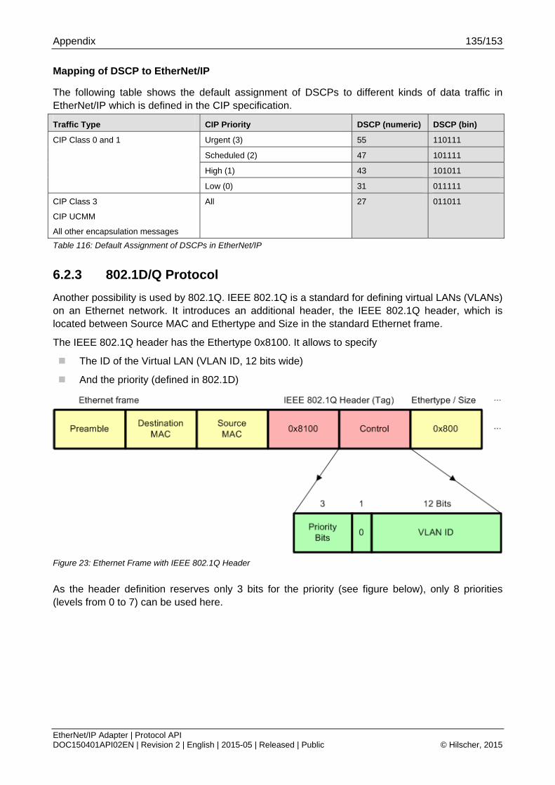
Appendix 135/153
EtherNet/IP Adapter | Protocol API DOC150401API02EN | Revision 2 | English | 2015-05 | Released | Public © Hilscher, 2015
Mapping of DSCP to EtherNet/IP
The following table shows the default assignment of DSCPs to different kinds of data traffic in EtherNet/IP which is defined in the CIP specification.
Traffic Type CIP Priority DSCP (numeric) DSCP (bin)
Urgent (3) 55 110111
Scheduled (2) 47 101111
High (1) 43 101011
CIP Class 0 and 1
Low (0) 31 011111
CIP Class 3
CIP UCMM
All other encapsulation messages
All 27 011011
Table 116: Default Assignment of DSCPs in EtherNet/IP
6.2.3 802.1D/Q Protocol
Another possibility is used by 802.1Q. IEEE 802.1Q is a standard for defining virtual LANs (VLANs) on an Ethernet network. It introduces an additional header, the IEEE 802.1Q header, which is located between Source MAC and Ethertype and Size in the standard Ethernet frame.
The IEEE 802.1Q header has the Ethertype 0x8100. It allows to specify
The ID of the Virtual LAN (VLAN ID, 12 bits wide)
And the priority (defined in 802.1D)
Figure 23: Ethernet Frame with IEEE 802.1Q Header
As the header definition reserves only 3 bits for the priority (see figure below), only 8 priorities (levels from 0 to 7) can be used here.
Appendix 136/153
EtherNet/IP Adapter | Protocol API DOC150401API02EN | Revision 2 | English | 2015-05 | Released | Public © Hilscher, 2015
Mapping of 802.1D/Q to EtherNet/IP
The following table shows the default assignment of 802.1D priorities to different kinds of data traffic in EtherNet/IP which is defined in the CIP specification.
Traffic Type CIP Priority 802.1D priority
Urgent (3) 6
Scheduled (2) 5
High (1) 5
CIP Class 0 and 1
Low (0) 3
CIP Class 3
CIP UCMM
All other encapsulation messages
All 3
Table 117: Default Assignment of 802.1D/Q Priorities in EtherNet/IP
6.2.4 The QoS Object
Within the EtherNet/IP implementation of QoS, the DiffServ mechanism is usually always present and does not need to be activated explicitly. In contrast to this, 802.1Q must explicitly be activated on all participating devices. The main capabilities of the QoS object are therefore:
To enable 802.1Q (VLAN tagging)
To enable setting parameters related to DiffServ (DSCP parameters)
For more information on the QoS object in the Hilscher EtherNet/IP adapter protocol stack see section “Quality of Service Object (Class Code: 0x48)“ of this document.
6.2.4.1 Enable 802.1Q (VLAN tagging)
The 802.1Q VLAN tagging mechanism can be turned on and off by setting attribute 1 (802.1Q Tag Enable) of the QoS object to value 1.

Appendix 137/153
EtherNet/IP Adapter | Protocol API DOC150401API02EN | Revision 2 | English | 2015-05 | Released | Public © Hilscher, 2015
6.3 DLR
This section intends to give a brief and compact overview about the basic facts and concepts of the DLR (Device level Ring) networking technology supported by Hilscher’s EtherNet/IP Adapter protocol stack.
DLR is a technology (based on a special protocol additionally to Ethernet/IP) for creating a single ring topology with media redundancy.
It is based on Layer 2 (Data link) of the ISO/OSI model of networking and thus transparent for higher layers (except the existence of the DLR object providing configuration and diagnosis capabilities).
In general, there are two kinds of nodes in the network:
Ring supervisors
Ring nodes
DLR requires all modules (both supervisors and normal ring nodes) to be equipped with two Ethernet ports and internal switching technology.
Each module within the DLR network checks the target address of the currently received DLR frame whether it matches its own MAC address.
If yes, it keeps the packet and processes it. It will not be propagated any further.
If no, it propagates the packet via the other port which did not receive the packet.
There is a ring topology so that all devices in the DLR network are each connected to two different neighbors with their two Ethernet ports. In order to avoid looping, one port of the (active) supervisor is blocked.
6.3.1 Ring Supervisors
There are two kinds of supervisors defined:
Active supervisors
Back-up supervisors
Note: The Hilscher EtherNet/IP stack does not support the ring supervisor mode!
Active supervisors
An active has the following duties:
It periodically sends beacon and announce frames.
It permanently verifies the ring integrity.
It reconfigures the ring in order to ensure operation in case of single faults.
It collects diagnostic information from the ring.
At least one active ring supervisor is required within a DLR network.
Back-up supervisors
It is recommended but not necessary that each DLR network should have at least one back-up supervisor. If the active supervisor of the network fails, the back-up supervisor will take over the duties of the active supervisor.
Appendix 138/153
EtherNet/IP Adapter | Protocol API DOC150401API02EN | Revision 2 | English | 2015-05 | Released | Public © Hilscher, 2015
6.3.2 Precedence Rule for Multi-Supervisor Operation
Multi-Supervisor Operation is allowed for DLR networks. If more than one supervisor is configured as active on the ring, the following rule applies in order to determine the supervisor which is relevant:
Each supervisor contains an internal precedence number which can be configured. The supervisor within the ring carrying the highest precedence number will be the active supervisor, the others will behave passively and switch back to the state of back-up supervisors.
6.3.3 Beacon and Announce Frames
Beacon frames and announce frames are both used to inform the devices within the ring about the transition (i.e. the topology change) from linear operation to ring operation of the network.
They differ in the following:
Direction
Beacon frames are sent in both directions.
Announce frames are sent only in one direction of the ring, however.
Frequency
Beacon frames are always sent every beacon interval. Usually, a beacon interval is defined to have an interval of 400 microseconds. However, beacon frames may be sent even faster up to an interval of 100 microseconds.
Announce frames are always sent in time intervals of one second.
Support for Precedence Number
Only Beacon frames contain the internal precedence number of the supervisor which sent them
Support for Network Fault Detection
Loss of beacon frames allows the active supervisor to detect and discriminate various types of network faults of the ring on its own.

Appendix 139/153
EtherNet/IP Adapter | Protocol API DOC150401API02EN | Revision 2 | English | 2015-05 | Released | Public © Hilscher, 2015
6.3.4 Ring Nodes
This subsection deals with modules in the ring, which does not have supervisor capabilities. These are denominated as (normal) ring nodes.
There are two types of normal ring nodes within the network:
Beacon-based
Announce-based
A DLR network may contain an arbitrary number of normal nodes.
Nodes of type beacon-based have the following capabilities
They implement the DLR protocol, but without the ring supervisor capability
They must be able to process beacon frames with hardware assistance
Nodes of type announce-based have the following capabilities
They implement the DLR protocol, but without the ring supervisor capability
They do not process beacon frames, they just forward beacon frames
They must be able to process announce frames
This type is often only a software solution
Note: Hilscher devices running an EtherNet/IP firmware always run as a beacon-based ring node.
A ring node (independently whether it works beacon-based or announce-based) may have three internal states.
IDLE_STATE
FAULT_STATE
NORMAL_STATE
For a beacon-based ring node, these states are defined as follows:
IDLE_STATE
The IDLE_STATE is the state which is reached after power-on. In IDLE_STATE the network operates as linear network, there is no ring support active. If on one port a beacon frame from a supervisor is received, the state changes to FAULT_STATE.
FAULT_STATE
The Ring node reaches the FAULT_STATE after the following conditions:
A. If a beacon frame from a supervisor is received on at least one port
B. If a beacon frame from a different supervisor than the currently active one is received on at least one port and the precedence of this supervisor is higher than that of the currently active one.
The FAULT_STATE provides partial ring support, but the ring is still not fully operative in FAULT_STATE. If the beacon frames have a time-out on both ports, the state will change to the IDLE_STATE. If on both ports a beacon frame is received and a beacon frame with RING_NORMAL_STATE has been received, the state changes to NORMAL_STATE.

Appendix 140/153
EtherNet/IP Adapter | Protocol API DOC150401API02EN | Revision 2 | English | 2015-05 | Released | Public © Hilscher, 2015
NORMAL_STATE
The Ring node reaches the NORMAL_STATE only after the following condition:
If a beacon frame from the active supervisor is received on both ports and a beacon frame with RING_NORMAL_STATE has been received
The NORMAL_STATE provides full ring support. The following conditions will cause a change to the FAULT_STATE:
A. A link failure has been detected.
B. A beacon frame with RING_FAULT_STATE has been received from the active supervisor on at least one port.
C. A beacon frame from the active supervisor had a time-out on at least one port
D. A beacon frame from a different supervisor than the currently active one is received on at least one port and the precedence of this supervisor is higher than that of the currently active one.
For an announce-based ring node, these states are defined as follows:
IDLE_STATE
The IDLE_STATE is the state which is reached after power-on. It can also be reached from any other state if the announce frame from the active supervisor has a time-out. In IDLE_STATE the network operates as linear network, there is no ring support active. If an announce frame with FAULT_STATE is received from a supervisor, the state changes to FAULT_STATE.
FAULT_STATE
The Ring node reaches the FAULT_STATE after the following conditions:
If the network is in IDLE_STATE and an announce frame with FAULT_STATE is received from any supervisor.
If the network is in NORMAL_STATE and an announce frame with FAULT_STATE is received from the active or a different supervisor.
If the network is in NORMAL_STATE and a link failure has been detected.
The FAULT_STATE provides partial ring support, but the ring is still not fully operative in FAULT_STATE.
If the announce frame from the active supervisor has a time-out, the state will fall back to the IDLE_STATE.
If an announce frame with NORMAL_STATE has been received from the active or a different supervisor, the state changes to NORMAL_STATE.
NORMAL_STATE
The Ring node reaches the NORMAL_STATE only after the following condition:
If the network is in IDLE_STATE and an announce frame with NORMAL_STATE is received from any supervisor.
If the network is in FAULT_STATE and an announce frame with NORMAL_STATE is received from the active or a different supervisor.
The NORMAL_STATE provides full ring support. The following conditions will cause a fall back to the FAULT_STATE:
Appendix 141/153
EtherNet/IP Adapter | Protocol API DOC150401API02EN | Revision 2 | English | 2015-05 | Released | Public © Hilscher, 2015
A link failure has been detected.
A announce frame with FAULT_STATE has been received from the active or a different supervisor.
The following conditions will cause a fall back to the IDLE _STATE:
The announce frame from the active supervisor has a time-out.
6.3.5 Normal Network Operation
In normal operation, the supervisor sends beacon and, if configured, announce frames in order to monitor the state of the network. Usual ring nodes and back-up supervisors receive these frames and react. The supervisor may send announce frames once per second and additionally, if an error is detected.
6.3.6 Rapid Fault/Restore Cycles
Sometimes a series of rapid fault and restore cycles may occur in the DLR network for instance if a connector is faulty. If the supervisor detects 5 faults within a time period of 30 seconds, it sets a flag (Rapid Fault/Restore Cycles) which must explicitly be reset by the user then. This can be accomplished via the “Clear Rapid Faults” service.
6.3.7 States of Supervisor
A ring supervisor may have five internal states.
IDLE_STATE
FAULT_STATE (active)
NORMAL_STATE (active)
FAULT_STATE (backup)
NORMAL_STATE (backup)
For a ring supervisor, these states are defined as follows:
FAULT_STATE (active)
The FAULT_STATE (active) is the state which is reached after power-on if the supervisor has been configured as supervisor.
The supervisor reaches the FAULT_STATE (active) after the following conditions:
A. As mentioned above, at power-on
B. From NORMAL_STATE (active):
If a link failure occurs or if a link status frame indicating a link failure is received from a ring node or if the beacon time-out timer expires on one port
C. From FAULT_STATE (backup):
If on both ports there is a time-out of the beacon frame from the currently active supervisor
The FAULT_STATE (active) provides partial ring support, but the ring is still not fully operative in FAULT_STATE (active).
If a beacon frame from a different supervisor than the currently active one is received on at least one port and the precedence of this supervisor is higher, the state will fall back to the FAULT_STATE (backup).
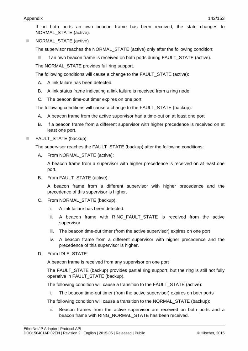
Appendix 142/153
EtherNet/IP Adapter | Protocol API DOC150401API02EN | Revision 2 | English | 2015-05 | Released | Public © Hilscher, 2015
If on both ports an own beacon frame has been received, the state changes to NORMAL_STATE (active).
NORMAL_STATE (active)
The supervisor reaches the NORMAL_STATE (active) only after the following condition:
If an own beacon frame is received on both ports during FAULT_STATE (active).
The NORMAL_STATE provides full ring support.
The following conditions will cause a change to the FAULT_STATE (active):
A. A link failure has been detected.
B. A link status frame indicating a link failure is received from a ring node
C. The beacon time-out timer expires on one port
The following conditions will cause a change to the FAULT_STATE (backup):
A. A beacon frame from the active supervisor had a time-out on at least one port
B. If a beacon frame from a different supervisor with higher precedence is received on at least one port.
FAULT_STATE (backup)
The supervisor reaches the FAULT_STATE (backup) after the following conditions:
A. From NORMAL_STATE (active):
A beacon frame from a supervisor with higher precedence is received on at least one port.
B. From FAULT_STATE (active):
A beacon frame from a different supervisor with higher precedence and the precedence of this supervisor is higher.
C. From NORMAL_STATE (backup):
i. A link failure has been detected.
ii. A beacon frame with RING_FAULT_STATE is received from the active supervisor
iii. The beacon time-out timer (from the active supervisor) expires on one port
iv. A beacon frame from a different supervisor with higher precedence and the precedence of this supervisor is higher.
D. From IDLE_STATE:
A beacon frame is received from any supervisor on one port
The FAULT_STATE (backup) provides partial ring support, but the ring is still not fully operative in FAULT_STATE (backup).
The following condition will cause a transition to the FAULT_STATE (active):
i. The beacon time-out timer (from the active supervisor) expires on both ports
The following condition will cause a transition to the NORMAL_STATE (backup):
ii. Beacon frames from the active supervisor are received on both ports and a beacon frame with RING_NORMAL_STATE has been received.

Appendix 143/153
EtherNet/IP Adapter | Protocol API DOC150401API02EN | Revision 2 | English | 2015-05 | Released | Public © Hilscher, 2015
The following condition will cause a transition to the IDLE_STATE:
iii. The beacon time-out timer (from the active supervisor) expires on both ports
NORMAL_STATE (backup)
The supervisor reaches the NORMAL_STATE (backup) only after the following condition:
Beacon frames from the active supervisor are received on both ports and a beacon frame with RING_NORMAL_STATE has been received.
The NORMAL_STATE (backup) provides full ring support. The following conditions will cause a change to the FAULT_STATE (backup):
A. A link failure has been detected.
B. A beacon frame with RING_FAULT_STATE has been received from the active supervisor on at least one port.
C. The beacon time-out timer (from the active supervisor) expires on both ports.
D. A beacon frame from a different supervisor with higher precedence and the precedence of this supervisor is higher.
IDLE_STATE
The IDLE_STATE is the state which is reached after power-on if the supervisor has not been configured as supervisor.
In IDLE_STATE the network operates as linear network, there is no ring support active. If on one port a beacon frame from a supervisor is received, the state changes to FAULT_STATE (backup).
For more details refer to the DLR specification in reference [4], section “9-5 Device Level Ring”.
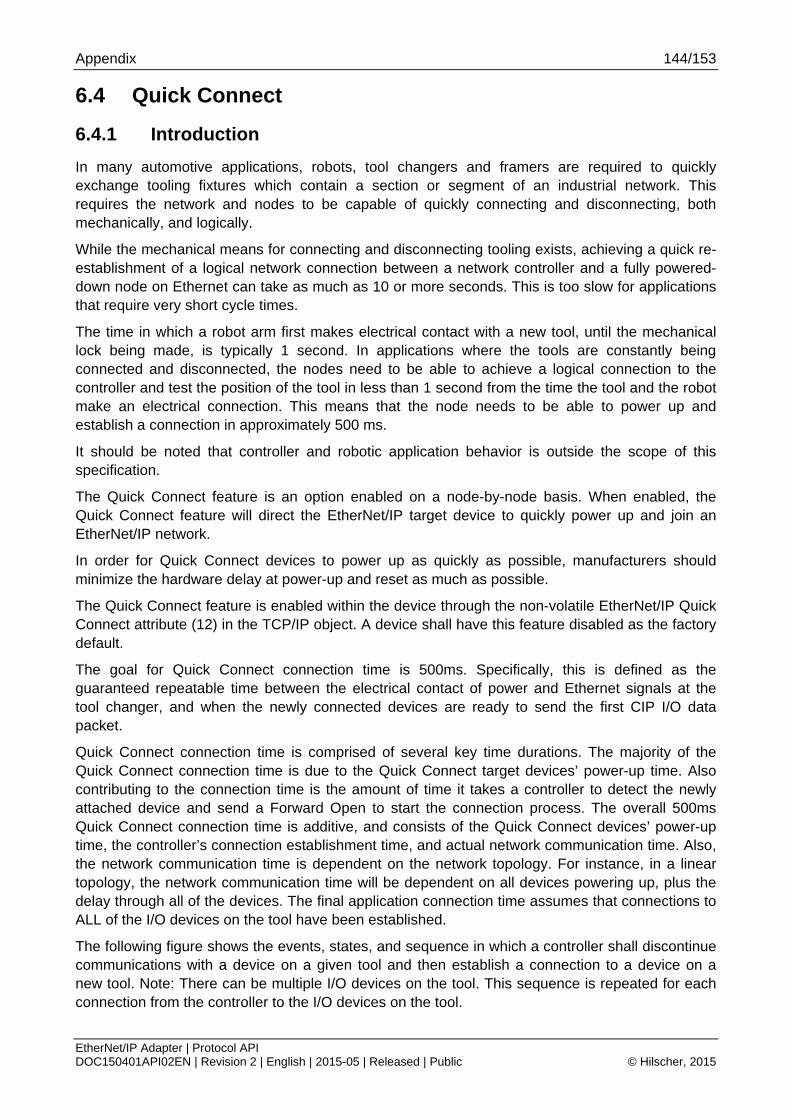
Appendix 144/153
EtherNet/IP Adapter | Protocol API DOC150401API02EN | Revision 2 | English | 2015-05 | Released | Public © Hilscher, 2015
6.4 Quick Connect
6.4.1 Introduction
In many automotive applications, robots, tool changers and framers are required to quickly exchange tooling fixtures which contain a section or segment of an industrial network. This requires the network and nodes to be capable of quickly connecting and disconnecting, both mechanically, and logically.
While the mechanical means for connecting and disconnecting tooling exists, achieving a quick re-establishment of a logical network connection between a network controller and a fully powered-down node on Ethernet can take as much as 10 or more seconds. This is too slow for applications that require very short cycle times.
The time in which a robot arm first makes electrical contact with a new tool, until the mechanical lock being made, is typically 1 second. In applications where the tools are constantly being connected and disconnected, the nodes need to be able to achieve a logical connection to the controller and test the position of the tool in less than 1 second from the time the tool and the robot make an electrical connection. This means that the node needs to be able to power up and establish a connection in approximately 500 ms.
It should be noted that controller and robotic application behavior is outside the scope of this specification.
The Quick Connect feature is an option enabled on a node-by-node basis. When enabled, the Quick Connect feature will direct the EtherNet/IP target device to quickly power up and join an EtherNet/IP network.
In order for Quick Connect devices to power up as quickly as possible, manufacturers should minimize the hardware delay at power-up and reset as much as possible.
The Quick Connect feature is enabled within the device through the non-volatile EtherNet/IP Quick Connect attribute (12) in the TCP/IP object. A device shall have this feature disabled as the factory default.
The goal for Quick Connect connection time is 500ms. Specifically, this is defined as the guaranteed repeatable time between the electrical contact of power and Ethernet signals at the tool changer, and when the newly connected devices are ready to send the first CIP I/O data packet.
Quick Connect connection time is comprised of several key time durations. The majority of the Quick Connect connection time is due to the Quick Connect target devices’ power-up time. Also contributing to the connection time is the amount of time it takes a controller to detect the newly attached device and send a Forward Open to start the connection process. The overall 500ms Quick Connect connection time is additive, and consists of the Quick Connect devices’ power-up time, the controller’s connection establishment time, and actual network communication time. Also, the network communication time is dependent on the network topology. For instance, in a linear topology, the network communication time will be dependent on all devices powering up, plus the delay through all of the devices. The final application connection time assumes that connections to ALL of the I/O devices on the tool have been established.
The following figure shows the events, states, and sequence in which a controller shall discontinue communications with a device on a given tool and then establish a connection to a device on a new tool. Note: There can be multiple I/O devices on the tool. This sequence is repeated for each connection from the controller to the I/O devices on the tool.

Appendix 145/153
EtherNet/IP Adapter | Protocol API DOC150401API02EN | Revision 2 | English | 2015-05 | Released | Public © Hilscher, 2015
Figure 24: Quick Connect System Sequence Diagram
There are two classes of Quick Connect devices.
Class A Quick Connect target devices is able to power-up, send the first Gratuitous ARP packet, and be ready to accept a TCP connection in less than 350ms.
Class B Quick Connect target devices shall be able to power-up, send the first Gratuitous ARP packet, and be ready to accept a TCP connection in less than 2 seconds.
6.4.2 Requirements
EtherNet/IP target devices supporting Quick Connect must adhere to the following requirements:
In order to be able to establish a physical link as fast as possible all Ethernet ports shall be set to 100 MBit/s and full duplex
When in Quick Connect mode Quick Connect devices shall not use Auto-MDIX (detection of the required cable connection type)
To enable the use of straight-thru cables when Auto-MIDX is disabled, the following rules shall be applied:
A. On a device with only one port: the port shall be configured as MDI.
B. On devices with 2 external Ethernet ports:
The labels for the 2 external ports shall include an ordinal indication (e.g.: Port 1 and Port 2, or A and B)
The port with the lower ordinal indication shall be configured as MDI.
The port with the upper ordinal indication shall be configured as MDIX.
The target device shall support EtherNet/IP Quick Connect attribute (12) in the TCP/IP Object that enables the Quick Connect feature.
The target device shall have the Quick Connect keywords and values included in the device’s EDS file.

Appendix 146/153
EtherNet/IP Adapter | Protocol API DOC150401API02EN | Revision 2 | English | 2015-05 | Released | Public © Hilscher, 2015
6.5 Hilscher specific CIP services
6.5.1 Common
6.5.1.1 Reset Object (0xFF32)
The Hilscher specific “Reset” service sets the whole object back to its initial state.
Request Service Data Field Parameters:
There are no request service data parameters.
Success Response Service Data Field Parameters:
There are no response service data parameters.
6.5.1.2 Get Attribute Option (0xFF33)
The Hilscher specific “Get Attribute Option” service returns the option flags of the specified attribute.
Request Service Data Field Parameters:
There are no request service data parameters.
Success Response Service Data Field Parameters:
Name Byte Size Description
Option Flags 2
/* Flags for access control */ #define CIP_FLG_SET_ACCESS_BUS 0x0000 #define CIP_FLG_SET_ACCESS_USER 0x0010 #define CIP_FLG_SET_ACCESS_ADMIN 0x0020 #define CIP_FLG_SET_ACCESS_NONE 0x0030 #define CIP_FLG_GET_ACCESS_BUS 0x0000 #define CIP_FLG_GET_ACCESS_USER 0x0040 #define CIP_FLG_GET_ACCESS_ADMIN 0x0080 #define CIP_FLG_GET_ACCESS_NONE 0x00C0 #define CIP_FLG_NOTIFICATION_ENABLE 0x4000 #define CIP_FLG_ATTRIBUTE_DISABLE 0x8000
Table 118: Hilscher Service – Get Attribute Option – Response Data Parameters

Appendix 147/153
EtherNet/IP Adapter | Protocol API DOC150401API02EN | Revision 2 | English | 2015-05 | Released | Public © Hilscher, 2015
6.5.1.3 Set Attribute Option (0xFF34)
The Hilscher specific “Set Attribute Option” service writes the option flags of the specified attribute.
Request Service Data Field Parameters:
Name Byte Size Description
Option Mask 2
This mask allows setting specific option flags without touching other flags that are not of interest.
In this mask field set the bits that correspond to the flags you want to set in the field “Option flags”.
Option Flags 2
/* Flags for access control */ #define CIP_FLG_SET_ACCESS_BUS 0x0000 #define CIP_FLG_SET_ACCESS_USER 0x0010 #define CIP_FLG_SET_ACCESS_ADMIN 0x0020 #define CIP_FLG_SET_ACCESS_NONE 0x0030 #define CIP_FLG_GET_ACCESS_BUS 0x0000 #define CIP_FLG_GET_ACCESS_USER 0x0040 #define CIP_FLG_GET_ACCESS_ADMIN 0x0080 #define CIP_FLG_GET_ACCESS_NONE 0x00C0 #define CIP_FLG_NOTIFICATION_ENABLE 0x4000 #define CIP_FLG_ATTRIBUTE_DISABLE 0x8000
Table 119: Hilscher Service – Set Attribute Option – Request Data Parameters
Success Response Service Data Field Parameters:
There are no response service data parameters.
6.5.2 Assembly Object
6.5.2.1 Create (0x0401)
The Hilscher specific “Create” service creates a new assembly instance.
Request Service Data Field Parameters:
Name Byte Size Description
Assembly Instance ID
4 CIP Instance ID
Minimum Size 2
Maximum Size 2
The minimum and maximum size fields define the connection size range that is allowed for this assembly instance.
Example:
1) Min Size = 4 and Max Size = 4: The connection size MUST be 4. No other size is allowed.
2) Min Size = 2 and Max Size = 16: The connection size can be between 2 and 16. If it is 2, then only the first 2 bytes of this assembly are transmitted via the connection.
Parameter Flags 2 #define CIP_AS_PARAM_FIX_SIZE 0x0001

Appendix 148/153
EtherNet/IP Adapter | Protocol API DOC150401API02EN | Revision 2 | English | 2015-05 | Released | Public © Hilscher, 2015
Name Byte Size Description
#define CIP_AS_PARAM_TYPE_MSK 0xF000 #define CIP_AS_PARAM_TYPE_CONSUMER 0x0000 #define CIP_AS_PARAM_TYPE_PRODUCER 0x1000 #define CIP_AS_PARAM_TYPE_HB_LISTENONLY 0x2000 #define CIP_AS_PARAM_TYPE_HB_INPUTONLY 0x3000 #define CIP_AS_PARAM_TYPE_CONFIG 0x4000 #define CIP_AS_PARAM_RT_FORMAT_MSK 0x0F00 #define CIP_AS_PARAM_RT_FORMAT_PURE 0x0000 #define CIP_AS_PARAM_RT_FORMAT_NULL 0x0100 #define CIP_AS_PARAM_RT_FORMAT_HB 0x0300 #define CIP_AS_PARAM_RT_FORMAT_RUNIDLE 0x0400 #define CIP_AS_PARAM_RT_FORMAT_SAFETY 0x0500
Table 120: Hilscher Service – Create – Request Data Parameters
Success Response Service Data Field Parameters:
There are no response service data parameters.
6.5.2.2 Delete (0x0402)
The Hilscher specific “Delete” service deletes an assembly instance.
Request Service Data Field Parameters:
There are no request service data parameters.
Success Response Service Data Field Parameters:
There are no response service data parameters.
6.5.2.3 Add Member (0x0403)
The Hilscher specific “Add member” service adds a member to a specific assembly instance.
Request Service Data Field Parameters:
Name Byte Size Description
Data Size 2 Number of bytes this member occupies (e.g. the byte size of the attribute the path points to).
Path Size 2 Size of path in bytes (maximum number is 9)
Path max. 9
CIP Path to member. Either 8 bit or 16 bit encoded. Encoding is base on the packed EPATH format described in the CIP specification (Volume 1 Edition 3.16. chapter C-1.4.2).
Example:
1) 8 Bit:
[20][08][24][01][30][0C]
Class 8, Instance 1, Attribute 12
2) 16 Bit:
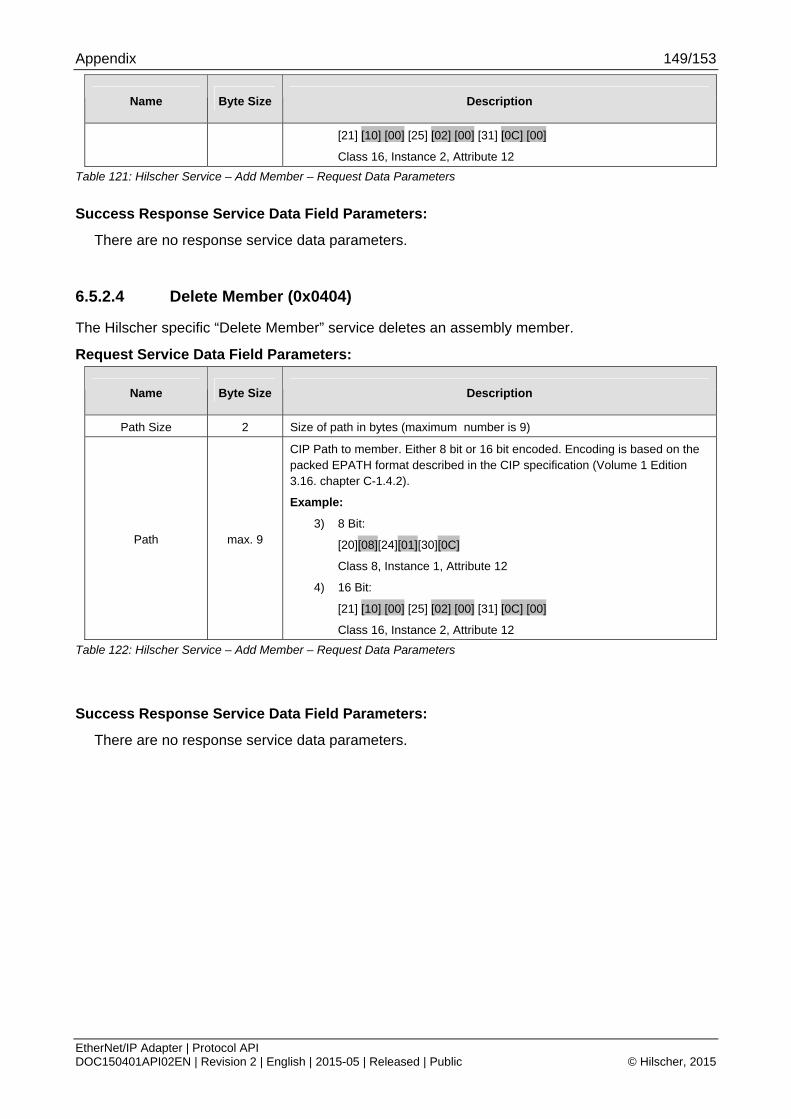
Appendix 149/153
EtherNet/IP Adapter | Protocol API DOC150401API02EN | Revision 2 | English | 2015-05 | Released | Public © Hilscher, 2015
Name Byte Size Description
[21] [10] [00] [25] [02] [00] [31] [0C] [00]
Class 16, Instance 2, Attribute 12
Table 121: Hilscher Service – Add Member – Request Data Parameters
Success Response Service Data Field Parameters:
There are no response service data parameters.
6.5.2.4 Delete Member (0x0404)
The Hilscher specific “Delete Member” service deletes an assembly member.
Request Service Data Field Parameters:
Name Byte Size Description
Path Size 2 Size of path in bytes (maximum number is 9)
Path max. 9
CIP Path to member. Either 8 bit or 16 bit encoded. Encoding is based on the packed EPATH format described in the CIP specification (Volume 1 Edition 3.16. chapter C-1.4.2).
Example:
3) 8 Bit:
[20][08][24][01][30][0C]
Class 8, Instance 1, Attribute 12
4) 16 Bit:
[21] [10] [00] [25] [02] [00] [31] [0C] [00]
Class 16, Instance 2, Attribute 12
Table 122: Hilscher Service – Add Member – Request Data Parameters
Success Response Service Data Field Parameters:
There are no response service data parameters.

Appendix 150/153
EtherNet/IP Adapter | Protocol API DOC150401API02EN | Revision 2 | English | 2015-05 | Released | Public © Hilscher, 2015
6.6 List of Figures Figure 1: Default Hilscher Device Object Model................................................................................................................ 12 Figure 2: Configuration Sequence Using the Basic Configuration Set .............................................................................. 43 Figure 3: Configuration Sequence Using the Extended Packet Set .................................................................................. 46 Figure 4: Non-Volatile CIP Object Attributes ..................................................................................................................... 47 Figure 5: Sequence Diagram for the EIP_APS_SET_CONFIGURATION_PARAMETERS_REQ/CNF Packet ...................... 49 Figure 6: Sequence diagram for the EIP_APS_SET_PARAMETER_REQ/CNF packet ....................................................... 59 Figure 7: Sequence Diagram for the EIP_APS_CONFIG_DONE_REQ/CNF Packet .......................................................... 62 Figure 8: Sequence Diagram for the EIP_OBJECT_MR_REGISTER_REQ/CNF Packet for the Stack Packet Set............. 64 Figure 9: Sequence Diagram for the EIP_OBJECT_AS_REGISTER_REQ/CNF Packet for the Stack Packet Set............. 68 Figure 10: Sequence Diagram for the EIP_OBJECT_ID_SETDEVICEINFO_REQ/CNF Packet for the Stack Packet Set 73 Figure 11: Sequence Diagram for the EIP_OBJECT_REGISTER_SERVICE_REQ/CNF Packet for the Stack Packet Set 78 Figure 12: Sequence Diagram for the EIP_OBJECT_CIP_SERVICE_REQ/CNF Packet for the Stack Packet Set........... 84 Figure 13: Sequence Diagram for the EIP_OBJECT_RESET_IND/RES Packet for the Basic Packet Set........................ 91 Figure 14: Sequence Diagram for the EIP_OBJECT_CONNECTION_IND/RES Packet for the Stack Packet Set............ 98 Figure 15: Sequence Diagram for the EIP_OBJECT_CL3_SERVICE_IND/RES Packet for the Stack Packet Set......... 107 Figure 16: Sequence Diagram for the EIP_OBJECT_CL3_SERVICE_IND/RES (Sequence Count Handling– Use case 1)
.............................................................................................................................................................................. 109 Figure 17: Sequence Diagram for the EIP_OBJECT_CL3_SERVICE_IND/RES (Sequence Count Handling– Use case 2)
.............................................................................................................................................................................. 110 Figure 18: Sequence Diagram for the EIP_OBJECT_CL3_SERVICE_IND/RES (Sequence Count Handling– Use case 3)
.............................................................................................................................................................................. 111 Figure 19: Sequence Diagram for the EIP_OBJECT_CL3_SERVICE_IND/RES (Sequence Count Handling– Use case 4)
.............................................................................................................................................................................. 112 Figure 20: Sequence Diagram for the EIP_OBJECT_CIP_OBJECT_CHANGE_IND/RES Packet for the Stack Packet Set
.............................................................................................................................................................................. 116 Figure 21: Sequence Diagram for the EIP_APS_GET_MS_NS_REQ/CNF Packet........................................................... 123 Figure 22: TOS Byte in IP v4 Frame Definition ............................................................................................................... 134 Figure 23: Ethernet Frame with IEEE 802.1Q Header .................................................................................................... 135 Figure 24: Quick Connect System Sequence Diagram ................................................................................................... 145
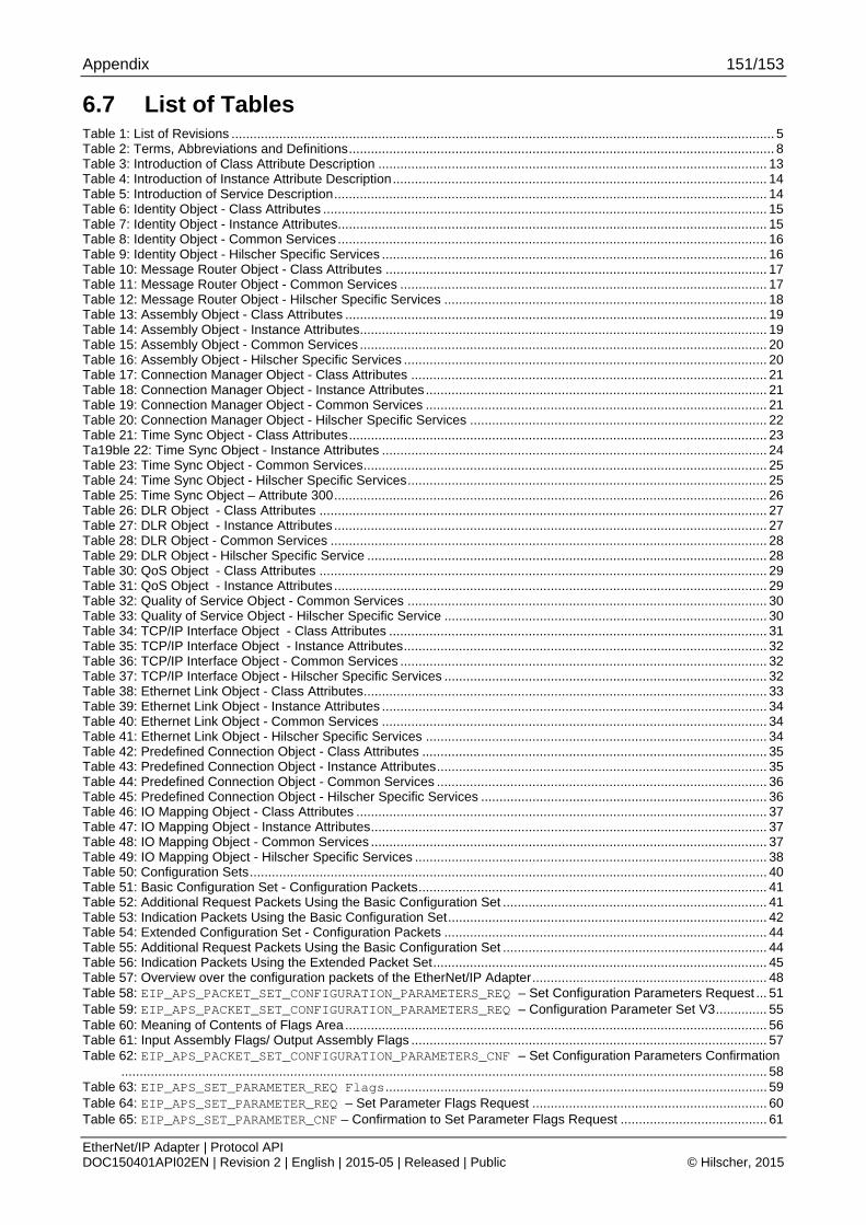
Appendix 151/153
EtherNet/IP Adapter | Protocol API DOC150401API02EN | Revision 2 | English | 2015-05 | Released | Public © Hilscher, 2015
6.7 List of Tables Table 1: List of Revisions .................................................................................................................................................... 5 Table 2: Terms, Abbreviations and Definitions.................................................................................................................... 8 Table 3: Introduction of Class Attribute Description .......................................................................................................... 13 Table 4: Introduction of Instance Attribute Description...................................................................................................... 14 Table 5: Introduction of Service Description...................................................................................................................... 14 Table 6: Identity Object - Class Attributes ......................................................................................................................... 15 Table 7: Identity Object - Instance Attributes..................................................................................................................... 15 Table 8: Identity Object - Common Services ..................................................................................................................... 16 Table 9: Identity Object - Hilscher Specific Services ......................................................................................................... 16 Table 10: Message Router Object - Class Attributes ........................................................................................................ 17 Table 11: Message Router Object - Common Services .................................................................................................... 17 Table 12: Message Router Object - Hilscher Specific Services ........................................................................................ 18 Table 13: Assembly Object - Class Attributes ................................................................................................................... 19 Table 14: Assembly Object - Instance Attributes............................................................................................................... 19 Table 15: Assembly Object - Common Services ............................................................................................................... 20 Table 16: Assembly Object - Hilscher Specific Services ................................................................................................... 20 Table 17: Connection Manager Object - Class Attributes ................................................................................................. 21 Table 18: Connection Manager Object - Instance Attributes............................................................................................. 21 Table 19: Connection Manager Object - Common Services ............................................................................................. 21 Table 20: Connection Manager Object - Hilscher Specific Services ................................................................................. 22 Table 21: Time Sync Object - Class Attributes.................................................................................................................. 23 Ta19ble 22: Time Sync Object - Instance Attributes ......................................................................................................... 24 Table 23: Time Sync Object - Common Services.............................................................................................................. 25 Table 24: Time Sync Object - Hilscher Specific Services.................................................................................................. 25 Table 25: Time Sync Object – Attribute 300...................................................................................................................... 26 Table 26: DLR Object - Class Attributes .......................................................................................................................... 27 Table 27: DLR Object - Instance Attributes ...................................................................................................................... 27 Table 28: DLR Object - Common Services ....................................................................................................................... 28 Table 29: DLR Object - Hilscher Specific Service ............................................................................................................. 28 Table 30: QoS Object - Class Attributes .......................................................................................................................... 29 Table 31: QoS Object - Instance Attributes ...................................................................................................................... 29 Table 32: Quality of Service Object - Common Services .................................................................................................. 30 Table 33: Quality of Service Object - Hilscher Specific Service ........................................................................................ 30 Table 34: TCP/IP Interface Object - Class Attributes ....................................................................................................... 31 Table 35: TCP/IP Interface Object - Instance Attributes................................................................................................... 32 Table 36: TCP/IP Interface Object - Common Services .................................................................................................... 32 Table 37: TCP/IP Interface Object - Hilscher Specific Services ........................................................................................ 32 Table 38: Ethernet Link Object - Class Attributes.............................................................................................................. 33 Table 39: Ethernet Link Object - Instance Attributes ......................................................................................................... 34 Table 40: Ethernet Link Object - Common Services ......................................................................................................... 34 Table 41: Ethernet Link Object - Hilscher Specific Services ............................................................................................. 34 Table 42: Predefined Connection Object - Class Attributes .............................................................................................. 35 Table 43: Predefined Connection Object - Instance Attributes.......................................................................................... 35 Table 44: Predefined Connection Object - Common Services .......................................................................................... 36 Table 45: Predefined Connection Object - Hilscher Specific Services .............................................................................. 36 Table 46: IO Mapping Object - Class Attributes ................................................................................................................ 37 Table 47: IO Mapping Object - Instance Attributes............................................................................................................ 37 Table 48: IO Mapping Object - Common Services ............................................................................................................ 37 Table 49: IO Mapping Object - Hilscher Specific Services ................................................................................................ 38 Table 50: Configuration Sets............................................................................................................................................. 40 Table 51: Basic Configuration Set - Configuration Packets............................................................................................... 41 Table 52: Additional Request Packets Using the Basic Configuration Set ........................................................................ 41 Table 53: Indication Packets Using the Basic Configuration Set....................................................................................... 42 Table 54: Extended Configuration Set - Configuration Packets ........................................................................................ 44 Table 55: Additional Request Packets Using the Basic Configuration Set ........................................................................ 44 Table 56: Indication Packets Using the Extended Packet Set........................................................................................... 45 Table 57: Overview over the configuration packets of the EtherNet/IP Adapter................................................................ 48 Table 58: EIP_APS_PACKET_SET_CONFIGURATION_PARAMETERS_REQ – Set Configuration Parameters Request ... 51 Table 59: EIP_APS_PACKET_SET_CONFIGURATION_PARAMETERS_REQ – Configuration Parameter Set V3.............. 55 Table 60: Meaning of Contents of Flags Area ................................................................................................................... 56 Table 61: Input Assembly Flags/ Output Assembly Flags ................................................................................................. 57 Table 62: EIP_APS_PACKET_SET_CONFIGURATION_PARAMETERS_CNF – Set Configuration Parameters Confirmation
................................................................................................................................................................................ 58 Table 63: EIP_APS_SET_PARAMETER_REQ Flags........................................................................................................ 59 Table 64: EIP_APS_SET_PARAMETER_REQ – Set Parameter Flags Request ................................................................ 60 Table 65: EIP_APS_SET_PARAMETER_CNF – Confirmation to Set Parameter Flags Request ........................................ 61

Appendix 152/153
EtherNet/IP Adapter | Protocol API DOC150401API02EN | Revision 2 | English | 2015-05 | Released | Public © Hilscher, 2015
Table 66: EIP_APS_CONFIG_DONE_REQ – Signal end of configuration request.............................................................. 62 Table 67: EIP_APS_CONFIG_DONE_CNF – Confirmation of end of configuration Request .............................................. 63 Table 68: Address Ranges for the ulClass parameter ................................................................................................... 64 Table 69: EIP_OBJECT_MR_REGISTER_REQ – Request Command for register a new class object .............................. 66 Table 70: EIP_OBJECT_MR_REGISTER_CNF – Confirmation Command of register a new class object.......................... 66 Table 71: Assembly Instance Number Ranges ................................................................................................................. 67 Table 72: EIP_OBJECT_AS_REGISTER_REQ – Request Command for create an Assembly Instance............................ 69 Table 73: Assembly Instance Property Flags .................................................................................................................... 70 Table 74: EIP_OBJECT_AS_REGISTER_CNF – Confirmation Command of register a new class object.......................... 72 Table 75: EIP_OBJECT_ID_SETDEVICEINFO_REQ – Request Command for open a new connection .......................... 75 Table 76: EIP_OBJECT_ID_SETDEVICEINFO_CNF – Confirmation Command of setting device information................. 77 Table 77: EIP_OBJECT_READY_REQ - Register Service.................................................................................................. 79 Table 78: EIP_OBJECT_READY_CNF – Confirmation Command for Register Service Request ....................................... 80 Table 79: Generic Error (Variable ulGRC)......................................................................................................................... 81 Table 80: Extended error codes for the connection manager............................................................................................ 83 Table 81: EIP_OBJECT_CIP_SERVICE_REQ – CIP Service Request ............................................................................ 85 Table 82: EIP_OBJECT_CIP_SERVICE_CNF – Confirmation to CIP Service Request .................................................... 87 Table 83 RCX_SET_FW_PARAMETER_REQ ParameterID ............................................................................................ 88 Table 84: Overview over the indications of the EtherNet/IP Adapter................................................................................. 89 Table 85: Allowed Values of ulResetTyp ....................................................................................................................... 90 Table 86: EIP_OBJECT_RESET_IND – Reset Request from Bus Indication .................................................................... 92 Table 87: EIP_OBJECT_RESET_RES – Response to Indication to Reset Request .......................................................... 93 Table 88: Meaning of variable ulConnectionState...................................................................................................... 94 Table 89: Meaning of variable bConnType....................................................................................................................... 94 Table 90: Meaning of Variable bPriority ...................................................................................................................... 95 Table 91: Coding of Timeout Multiplier Values.................................................................................................................. 96 Table 92: Meaning of Variable bTriggerType................................................................................................................ 96 Table 93: Meaning of Variable usOTConnParam.............................................................................................................. 96 Table 94: Priority ............................................................................................................................................................... 97 Table 95: Connection Type ............................................................................................................................................... 97 Table 96: Priority ............................................................................................................................................................... 98 Table 97: EIP_OBJECT_CONNECTION_IND – Indication of Connection ........................................................................ 101 Table 98: Specified Ranges of numeric Values of Service Codes (Variable ulService) ................................................. 104 Table 99: Service Codes for the Common Services according to the CIP specification.................................................. 105 Table 100: Most common General Status Codes............................................................................................................ 106 Table 101: Service Indication Use Cases and Sequence Count Handling...................................................................... 108 Table 102: EIP_OBJECT_CL3_SERVICE_IND - Indication of acyclic Data Transfer ..................................................... 114 Table 103: EIP_OBJECT_CL3_SERVICE_RES – Response to Indication of acyclic Data Transfer................................ 115 Table 104: EIP_OBJECT_CIP_OBJECT_CHANGE_IND – CIP Object Change Indication............................................... 117 Table 105: EIP_OBJECT_CIP_OBJECT_CHANGE_RES – Response to CIP Object Change Indication ......................... 118 Table 106: RCX_LINK_STATUS_CHANGE_IND_T - Link Status Change Indication........................................................ 120 Table 107: Structure RCX_LINK_STATUS_CHANGE_IND_DATA_T ................................................................................ 120 Table 108: RCX_LINK_STATUS_CHANGE_RES_T - Link Status Change Response....................................................... 121 Table 109: Overview over the additional services of the EtherNet/IP Adapter ................................................................ 122 Table 110: EIP_APS_GET_MS_NS_REQ – Get Module Status/ Network Status Request ............................................... 124 Table 111: EIP_APS_GET_MS_NS_CNF – Confirmation of Get Module Status/ Network Status Request ...................... 125 Table 112: Status/Error Codes of EtherNet/IP Stack ............................................................................................ 129 Table 113: General Error Codes according to CIP Standard .......................................................................................... 131 Table 114: Possible values of the Module Status............................................................................................................ 132 Table 115: Possible values of the Network Status .......................................................................................................... 133 Table 116: Default Assignment of DSCPs in EtherNet/IP ............................................................................................... 135 Table 117: Default Assignment of 802.1D/Q Priorities in EtherNet/IP............................................................................. 136 Table 118: Hilscher Service – Get Attribute Option – Response Data Parameters......................................................... 146 Table 119: Hilscher Service – Set Attribute Option – Request Data Parameters ............................................................ 147 Table 120: Hilscher Service – Create – Request Data Parameters ................................................................................ 148 Table 121: Hilscher Service – Add Member – Request Data Parameters....................................................................... 149 Table 122: Hilscher Service – Add Member – Request Data Parameters....................................................................... 149

Appendix 153/153
EtherNet/IP Adapter | Protocol API DOC150401API02EN | Revision 2 | English | 2015-05 | Released | Public © Hilscher, 2015
6.8 Contacts Headquarters Germany Hilscher Gesellschaft für Systemautomation mbH Rheinstrasse 15 65795 Hattersheim Phone: +49 (0) 6190 9907-0 Fax: +49 (0) 6190 9907-50 E-Mail: [email protected] Support Phone: +49 (0) 6190 9907-99 E-Mail: [email protected]
Subsidiaries
China Hilscher Systemautomation (Shanghai) Co. Ltd. 200010 Shanghai Phone: +86 (0) 21-6355-5161 E-Mail: [email protected] Support Phone: +86 (0) 21-6355-5161 E-Mail: [email protected] France Hilscher France S.a.r.l. 69500 Bron Phone: +33 (0) 4 72 37 98 40 E-Mail: [email protected] Support Phone: +33 (0) 4 72 37 98 40 E-Mail: [email protected] India Hilscher India Pvt. Ltd. New Delhi - 110 065 Phone: +91 11 26915430 E-Mail: [email protected] Italy Hilscher Italia S.r.l. 20090 Vimodrone (MI) Phone: +39 02 25007068 E-Mail: [email protected] Support Phone: +39 02 25007068 E-Mail: [email protected]
Japan Hilscher Japan KK Tokyo, 160-0022 Phone: +81 (0) 3-5362-0521 E-Mail: [email protected] Support Phone: +81 (0) 3-5362-0521 E-Mail: [email protected] Korea Hilscher Korea Inc. Seongnam, Gyeonggi, 463-400 Phone: +82 (0) 31-789-3715 E-Mail: [email protected] Switzerland Hilscher Swiss GmbH 4500 Solothurn Phone: +41 (0) 32 623 6633 E-Mail: [email protected] Support Phone: +49 (0) 6190 9907-99 E-Mail: [email protected] USA Hilscher North America, Inc. Lisle, IL 60532 Phone: +1 630-505-5301 E-Mail: [email protected] Support Phone: +1 630-505-5301 E-Mail: [email protected]