Ethernet Power quality Modbus-Ethernet gateway Emax...
9
UMG 508Emax peak demand management UMG 508Emax Peak Demand Management Ethernet Modbus-Ethernet gateway Memory 256 MB Power quality Emax Peak demand management GridVis ® ✔
Transcript of Ethernet Power quality Modbus-Ethernet gateway Emax...

UMG 508Emax peak demand management
UMG 508Emax Peak Demand Management
Ethernet
Modbus-Ethernet gateway
Memory 256 MB
Power quality
Emax
Peak demand management
GridVis®
✔

2
Reduce power peaks intelligently
• Constant logging of all electrical parameters• Integrated, intelligent control algorithms calculate the active power
trend and compare this with the preset target active power• Accurate intervention in the operating process • Short-term switching off of non-critical loads per user stipulations• If feedback processing is connected, only loads which are using power at
the time of the calculation are switched off or integrated in the trend value calculation
• Advantage: Avoidance of cost-intensive power peaks and indicationof cost saving potentials
Power analyser UMG 508 as basic equipment
• The UMG 508 is used as a basic device • Features of the UMG 508: - Multifunction device - Determination of load conditions of the electrical supply equipment
for the avoidance of overloading• Measurement and storage of all electrical variables including current and
power values - Visualisation of the maximum monitor measured values via
the device homepage - Includes system software GridVis®-Basic - Detailed information regarding the UMG 508 in chapter 02
Function principle – simple and precise
• On the basis of the incoming active power pulse at a digital input, or the overall effective power (transformer measurement) calculated by the measurement device, the Emax program determines the variables required in order to comply with a predefi ned kW target value
• Constant calculation of the mean value, momentary value, trend value and correction power within the set measurement period
• Load switching in case of exceeding the maximum• Load shedding takes place with consideration to the pre-defi ned priority • Target: Compliance with the specifi ed kW-maximum at the end of a measuring period with the fewest possible switching instances
• Authorisation of a feedback input (release) for each load of the Emax function (optional)
• In order to switch off consumers via expansion modules with digital outputs (FBM 10 R-NC) up to 64 channels are possible
Fig.: Load curve in daily routine
Fig.: Confi guration of electrical loads that can be switched off
UMG 508Emax peak demand management

3
UMG 508Emax peak demand management
Fig.: Via the device homepage it is possible to present the status display of the Emax measurement variables, the state of the actual switch-off actions and the status of the release (feedback as to whether the load is on / off)
Fig.: Peak demand manager UMG 508Emax 15-A insheet steel housing
Peak demand management of up to 64 load shedding stages depending on device type and Emax application
• Overall confi guration and evaluation via the UMG device homepage• Device parameters can be conveniently adjusted on the homepage• Extract of parametrisation possibilities: Target value, actual value for mean
value calculation, measurement period duration, off-time, pause time, availability
• Depending on the electrical loads the following are adjustable: Load name, priority, connection power, minimum switch-on duration, minimum switch-off duration, maximum switch-off duration and availability as a percentage
• The following measurement variables are stored in the device: - Mean effective power value synchronous to the measurement period reset - Trend value recording - Measurement period reset with state change• Evaluation takes place via the system software GridVis®
Peak demand manager UMG 508Emax 15-A in sheet steel housing - example systems
UMG 508Emax 15-A (item no.: 52.21.222)Maximum monitoring system with 15 load shedding stages in a sheet steel housing for wall mounting.
Dimensions in mm (H x W x D): 380 x 600 x 210
Colour: RAL 7035
Fully installed and wired: • 8 digital inputs, of which 1 digital input for active power pulses and 1 digital
input for resetting the measurement period• 15 relay outputs, 5 outputs directly controlled from the UMG 508 • 1 fi eld bus module FBM10 R-NC, item no. 15.06.078 with 10 relay outputs
(normally closed) including status display
UMG 508Emax 15-AE (item no.: 52.21.223)Maximum monitoring system with 15 load shedding stages and feedback in a sheet steel housing for wall mounting.
Dimensions in mm (H x W x D): 380 x 600 x 210
Colour: RAL 7035
Fully installed and wired: • 8 digital inputs, of which 1 digital input for active power pulses and 1 digital
input for resetting the measurement period • 15 relay outputs, 5 outputs directly controlled from the UMG 508 • 1 fi eld bus module FBM10 R-NC, item no. 15.06.078 with 10 relay outputs
(normally closed) plus status display • 1 fi eld bus module FBM10l, item no. 15.006.076 with 10 digital inputs
including status display
4
UMG 508Emax peak demand management
1920212223242526
27
293031
1718
28
Input:115 - 230V AC
L PE N
Output24 VDC / 1A
+-
15 min
161514131211
10987654321
MT2
A
MT2
A
L2L1
L3NPE
S1 S2S1 S2
S1 S2S1 S2
A1 A2
1412
11
2
A1 A2
1412
11
3
A1 A2
1412
11
4
A1 A2
1412
11
5
A1A2
1412
11
1
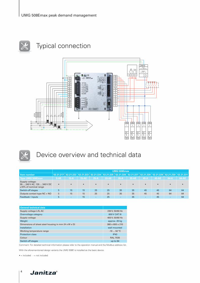
Typical connection
Device overview and technical data
UMG 508Emax
Item number 52.21.217 52.21.222 52.21.223 52.21.224 52.21.225 52.21.226 52.21.227 52.21.228 52.21.229 52.21.230 52.21.231
Type UMG 508Emax 5-AE 15-A 15-AE 25-A 25-AE 35-A 35-AE 45-A 45-AE 64-A 64-AESupply voltage:95 ... 240 V AC, 135 ... 340 V DC±10% of nominal range
• • • • • • • • • • •
Switch-off stages 5 15 15 25 25 35 35 45 45 64 64
Outputs contact type NC + NO 5 15 15 25 25 35 35 45 45 64 64
Feedback / inputs 5 - 15 - 25 - 35 - 45 - 64
General technical dataSupply voltage L-N, AC 230 V, 50/60 Hz
Overvoltage category 600 V CAT III
Supply voltage 400 V, 50/60 Hz
Weight approx. 20 kg
Dimensions of sheet steel housing in mm (H x W x D) 380 x 600 x 210
Installation wall mounted
Working temperature range -10 ... 50 °C
Protection class IP43
Colour RAL 7035
Switch-off stages up to 64
Comment: For detailed technical information please refer to the operation manual and the Modbus address list.
With the aforementioned design variants the UMG 508E is installed as the basic device.
• = included - = not included
5
UMG 508Emax peak demand management
GeneralUse in low and medium voltage networks •
Accuracy voltage measurement 0.1 %
Accuracy current measurement 0.2 %
Accuracy active energy (kWh, …/5 A) class 0.2
Number of measurement points per period 400
Seamless measurement •
RMS - momentary valueCurrent, voltage, frequency •
Active, reactive and apparent power / total and per phase •
Power factor / total and per phase •
Energy measurementActive, reactive and apparent energy [L1, L2, L3, ∑ L1–L3, ∑ L1–4] •
Number of tariffs 8
Recording of the mean valuesVoltage, current / actual and maximum •
Active, reactive and apparent power / actual and maximum •
Frequency / actual and maximum •
Demand calculation mode (bi-metallic function) / thermal •
Other measurementsOperating hours measurement •
Clock •
Weekly switch clock Jasic®
Measurement of the power qualityHarmonics per order / current and voltage 1st – 40th
Harmonic per order / active and reactive power 1st – 40th
Distortion factor THD-U in % •
Distortion factor THD-I in % •
Voltage unbalance •
Rotary fi eld indication •
Current and voltage, positive, zero and negative sequence component •
Transients > 50 µs
Error / event plotter function •
Short term interruptions 20 ms
Oscillogram function (waveform U and I) •
Full wave effective values (U, I, P, Q) •
Under and overvoltage recording •
Measured data recordingMemory (Flash) 256 MB
Mean, minimum, maximum values •
Measured data channels 8
Alarm messages •
Time stamp •
Time basis mean value freely user-defi ned
RMS averaging, arithmetic •
Displays and inputs / outputsLCD colour graphical display 320 x 240, 256 colours, 6 buttons •
Language selection •
Digital inputs 8
Digital outputs (as switch or pulse output) 5
Voltage and current inputs every 4
Password protection •
Peak demand management (optionally 64 channels) •
Communication
InterfacesRS485: 9.6 – 921.6 kbps (DSUB-9 connector) •
Profi bus DP: Up to 12 Mbps (DSUB-9 connector) •
Ethernet 10/100 Base-TX (RJ-45 socket) •
ProtocolsModbus RTU, Modbus TCP, Modbus RTU over Ethernet •
Modbus Gateway for Master-Slave confi guration •
Profi bus DP V0 •
HTTP (homepage confi gurable) •
SMTP (email) •
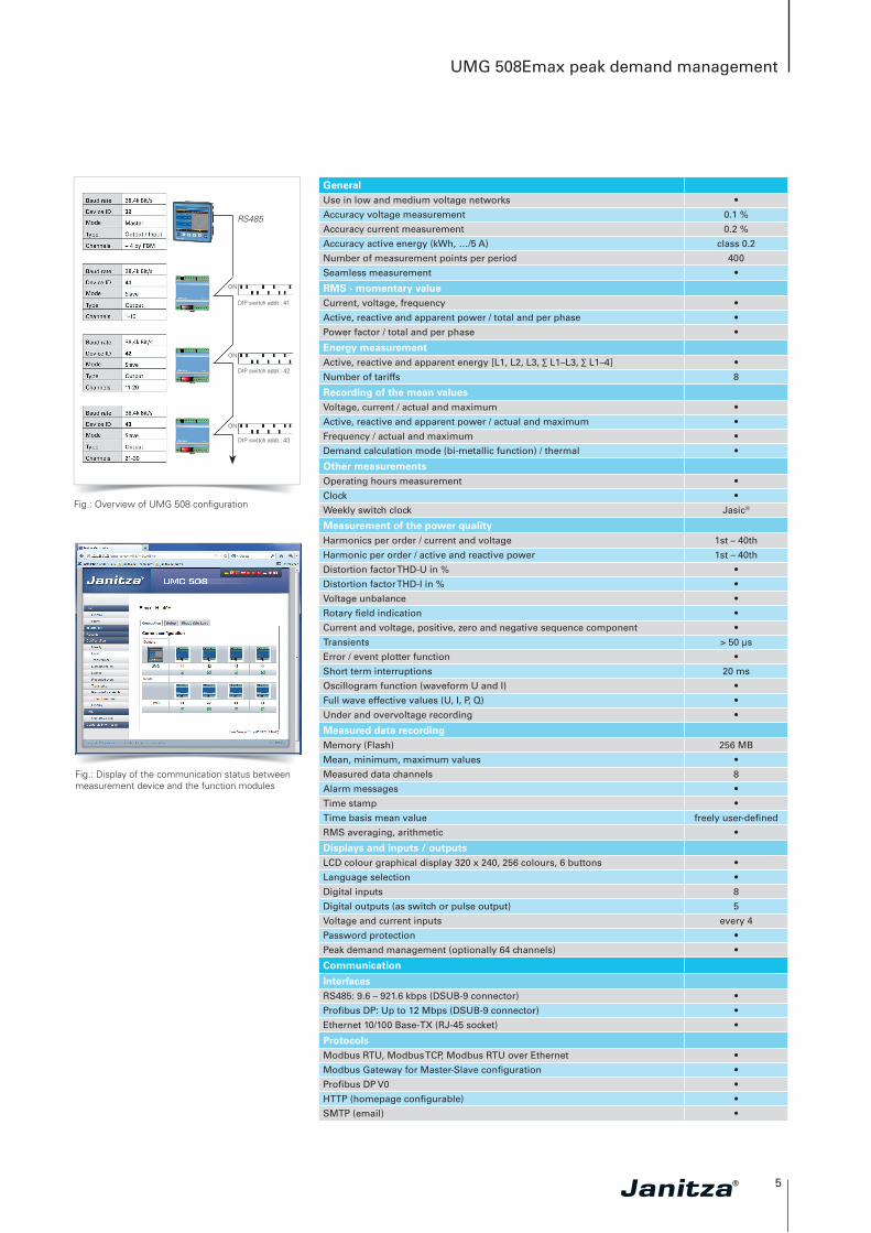
Fig.: Overview of UMG 508 confi guration
RS485
ON
ON
ON
DIP switch addr.: 41
DIP switch addr.: 42
DIP switch addr.: 43
Fig.: Display of the communication status between measurement device and the function modules
6
UMG 508Emax peak demand management
NTP (time synchronisation) •
TFTP •
FTP (File-Transfer) •
SNMP •
DHCP •
TCP/IP •
BACnet (optional) •
ICMP (Ping) •
Software GridVis®-Basic*1
Online and historic graphs •
Databases (Janitza DB, Derby DB); MySQL, MS SQL with higher GridVis® versions)
•
Manual reports (energy, power quality) •
Graphical programming •
Topology views •
Manual read-out of the measuring devices •
Graph sets •
Programming / threshold values / alarm managementApplication programs freely programmable 3
Graphical programming •
Programming via source code Jasic® •
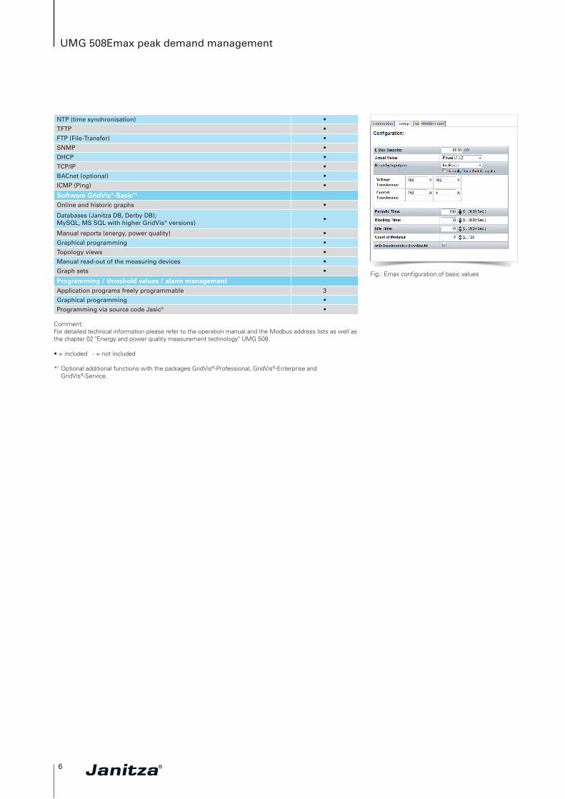
Fig.: Emax confi guration of basic values
Comment: For detailed technical information please refer to the operation manual and the Modbus address lists as well as the chapter 02 "Energy and power quality measurement technology" UMG 508. • = included - = not included *1 Optional additional functions with the packages GridVis®-Professional, GridVis®-Enterprise and
GridVis®-Service.
7
UMG 508Emax peak demand management
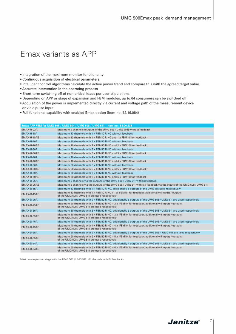
Emax variants as APP
• Integration of the maximum monitor functionality• Continuous acquisition of electrical parameters• Intelligent control algorithms calculate the active power trend and compare this with the agreed target value• Accurate intervention in the operating process • Short-term switching off of non-critical loads per user stipulations• Depending on APP or stage of expansion and FBM modules, up to 64 consumers can be switched off• Acquisition of the power is implemented directly via current and voltage path of the measurement device
or via a pulse input• Full functional capability with enabled Emax option (item no. 52.16.084)
Emax-APP FBM for UMG 605 / UMG 604 / UMG 508 / UMG 511 Item no.: 51.00.235 EMAX-H-02A Maximum 2 channels (outputs of the UMG 605 / UMG 604) without feedback
EMAX-H-10A Maximum 10 channels with 1 x FBM10 R-NC without feedback
EMAX-H-10AE Maximum 10 channels with 1 x FBM10 R-NC and 1 x FBM10I for feedback
EMAX-H-20A Maximum 20 channels with 2 x FBM10 R-NC without feedback
EMAX-H-20AE Maximum 20 channels with 2 x FBM10 R-NC and 2 x FBM10I for feedback
EMAX-H-30A Maximum 30 channels with 3 x FBM10 R-NC without feedback
EMAX-H-30AE Maximum 30 channels with 3 x FBM10 R-NC and 3 x FBM10I for feedback
EMAX-H-40A Maximum 40 channels with 4 x FBM10 R-NC without feedback
EMAX-H-40AE Maximum 40 channels with 4 x FBM10 R-NC and 4 x FBM10I for feedback
EMAX-H-50A Maximum 50 channels with 5 x FBM10 R-NC without feedback
EMAX-H-50AE Maximum 50 channels with 5 x FBM10 R-NC and 5 x FBM10I for feedback
EMAX-H-60A Maximum 60 channels with 6 x FBM10 R-NC without feedback
EMAX-H-60AE Maximum 60 channels with 6 x FBM10 R-NC and 6 x FBM10I for feedback
EMAX-D-05A Maximum 5 channels via the outputs of the UMG 508 / UMG 511 without feedback
EMAX-D-05AE Maximum 5 channels via the outputs of the UMG 508 / UMG 511 with 5 x feedback via the inputs of the UMG 508 / UMG 511
EMAX-D-15A Maximum 10 channels with 1 x FBM10 R-NC, additionally 5 outputs of the UMG are used respectively
EMAX-D-15AEMaximum 10 channels with 1 x FBM10 R-NC + 1 x FBM10I for feedback, additionally 5 inputs / outputs of the UMG 508 / UMG 511 are used respectively
EMAX-D-25A Maximum 20 channels with 2 x FBM10 R-NC, additionally 5 outputs of the UMG 508 / UMG 511 are used respectively
EMAX-D-25AEMaximum 20 channels with 2 x FBM10 R-NC + 2 x FBM10I for feedback, additionally 5 inputs / outputs of the UMG 508 / UMG 511 are used respectively
EMAX-D-35A Maximum 30 channels with 3 x FBM10 R-NC, additionally 5 outputs of the UMG 508 / UMG 511 are used respectively
EMAX-D-35AEMaximum 30 channels with 3 x FBM10 R-NC + 3 x FBM10I for feedback, additionally 5 inputs / outputs of the UMG 508 / UMG 511 are used respectively
EMAX-D-45A Maximum 40 channels with 4 x FBM10 R-NC, additionally 5 outputs of the UMG 508 / UMG 511 are used respectively
EMAX-D-45AEMaximum 40 channels with 4 x FBM10 R-NC + 4 x FBM10I for feedback, additionally 5 inputs / outputs of the UMG 508 / UMG 511 are used respectively
EMAX-D-55A Maximum 50 channels with 5 x FBM10 R-NC, additionally 5 outputs of the UMG 508 / UMG 511 are used respectively
EMAX-D-55AEMaximum 50 channels with 5 x FBM10 R-NC + 5 x FBM10I for feedback, additionally 5 inputs / outputs of the UMG 508 / UMG 511 are used respectively
EMAX-D-64A Maximum 60 channels with 6 x FBM10 R-NC, additionally 4 outputs of the UMG 508 / UMG 511 are used respectively
EMAX-D-64AEMaximum 60 channels with 6 x FBM10 R-NC + 6 x FBM10I for feedback, additionally 4 inputs / outputs of the UMG 508 / UMG 511 are used respectively
Maximum expansion stage with the UMG 508 / UMG 511: 64 channels with 64 feedbacks
8
UMG 508Emax peak demand management
Emax variants as APP
• Item no. 51.00.236 and item no. 51.00.237 contain no actuation of function modules• Switching off must take place via GLT / PLC• Read-out of switchings etc. not possible with Emax-APP FBM (item no. 51.00.235) via Modbus or Profibus
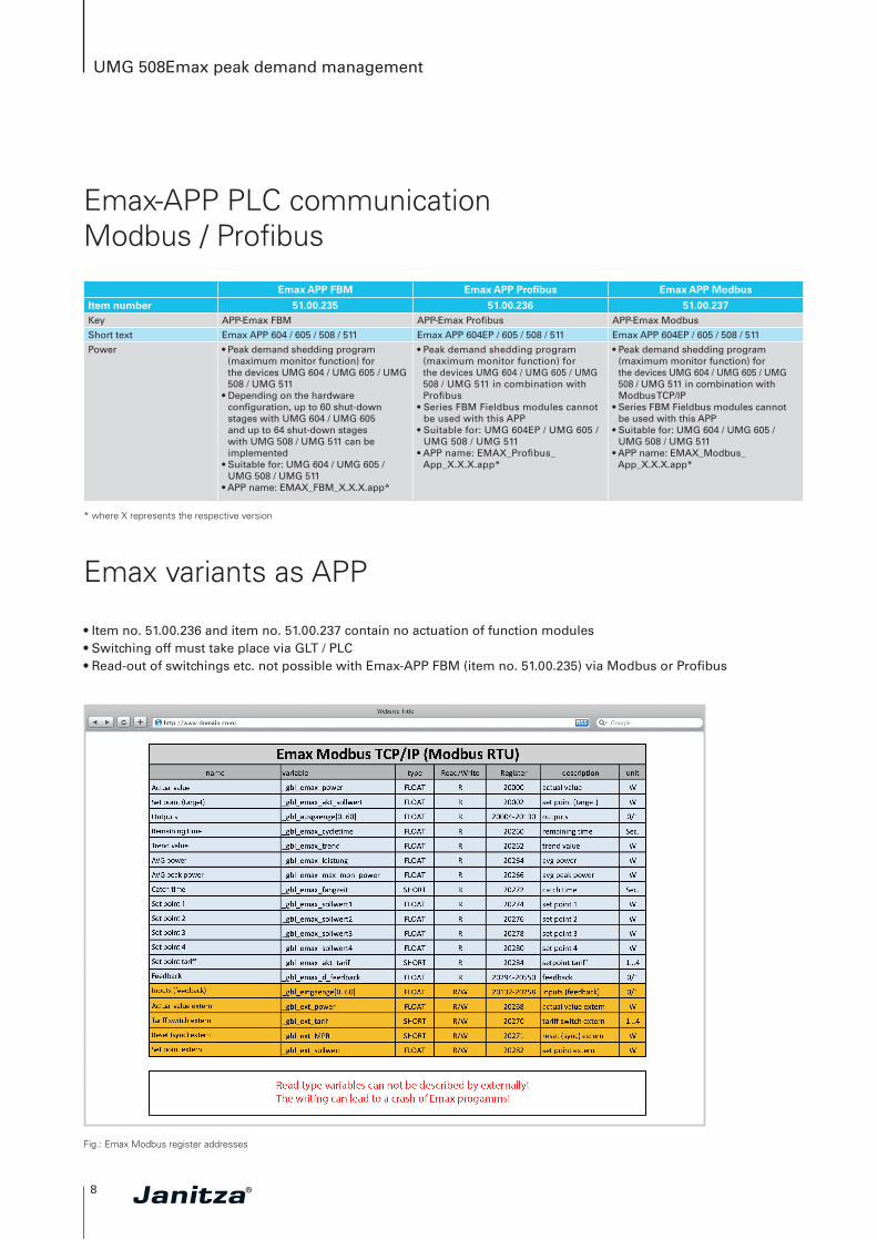
Emax APP FBM Emax APP Profibus Emax APP Modbus
Item number 51.00.235 51.00.236 51.00.237Key APP-Emax FBM APP-Emax Profibus APP-Emax Modbus
Short text Emax APP 604 / 605 / 508 / 511 Emax APP 604EP / 605 / 508 / 511 Emax APP 604EP / 605 / 508 / 511
Power • Peak demand shedding program (maximum monitor function) for the devices UMG 604 / UMG 605 / UMG 508 / UMG 511
• Depending on the hardware configuration, up to 60 shut-down stages with UMG 604 / UMG 605 and up to 64 shut-down stages with UMG 508 / UMG 511 can be implemented
• Suitable for: UMG 604 / UMG 605 / UMG 508 / UMG 511
• APP name: EMAX_FBM_X.X.X.app*
• Peak demand shedding program (maximum monitor function) for the devices UMG 604 / UMG 605 / UMG 508 / UMG 511 in combination with Profibus
• Series FBM Fieldbus modules cannot be used with this APP
• Suitable for: UMG 604EP / UMG 605 / UMG 508 / UMG 511
• APP name: EMAX_Profibus_App_X.X.X.app*
• Peak demand shedding program (maximum monitor function) for the devices UMG 604 / UMG 605 / UMG 508 / UMG 511 in combination with Modbus TCP/IP
• Series FBM Fieldbus modules cannot be used with this APP
• Suitable for: UMG 604 / UMG 605 / UMG 508 / UMG 511
• APP name: EMAX_Modbus_App_X.X.X.app*
* where X represents the respective version
Fig.: Emax Modbus register addresses
Emax-APP PLC communication Modbus / Profibus
Edition 03/2014 • All rights to technical changes are reserved.
Sal
es p
artn
er
Janitza electronics GmbHVor dem Polstück 1D-35633 LahnauDeutschland
Tel.: +49 6441 9642-0Fax: +49 6441 [email protected]
Smart Energy &Power Quality Solutions