EtherCAT User’s Guidemail.tolomatic.com/archives/PDFS/3600-4201_03_UserGuide... · 2018-07-13 ·...
15
3600-4201_03 EtherCAT User’s Guide ACSI Integrated Servo Motor/Drive/Controller
Transcript of EtherCAT User’s Guidemail.tolomatic.com/archives/PDFS/3600-4201_03_UserGuide... · 2018-07-13 ·...

3600-4201_03
EtherCAT User’s Guide ACSI Integrated Servo Motor/Drive/Controller
C O N T E N T S
Tolomatic User Guide: EtherCAT, ACSI Servo 3600-4201_03
[2]
Contents Introduction .................................................................................................................................................. 3
Network Configuration ................................................................................................................................. 3
Ethernet Cabling ........................................................................................................................................... 3
Tolomatic Motion Interface (TMI) Requirements ......................................................................................... 3
EtherCAT LED Indicators ............................................................................................................................... 4
Input Objects ................................................................................................................................................. 5
Output Objects .............................................................................................................................................. 7
A Note about EEPROM .................................................................................................................................. 9
Device Specific Serial Number .................................................................................................................... 10
Getting Started – The Basics ....................................................................................................................... 11
Terminology: Inputs and Outputs ....................................................................................................... 11
PLC Program Structure: Maintaining State ...................................................................................... 11
PLC Program Structure: Shadow Memory ....................................................................................... 12
Tables and Figures Table 1 - ACSI EtherCAT LED Indicators Blink Definitions ......................................................... 4 Table 2 - Input Object Definitions ............................................................................................... 5 Table 3 - Drive Status Bitmask Definition ................................................................................... 5 Table 4 - Drive Faults Bitmask Definition.................................................................................... 6 Table 5 - ACS Servo Drive/ACSI Remappable Registers ........................................................... 6 Table 6 - Output Object Definitions ............................................................................................ 7 Table 7 - Drive Command Definitions ......................................................................................... 8 Table 8 - Motion Types Definitions ............................................................................................. 9
Figure 1 - ESC Port Assignment ................................................................................................ 4 Figure 2 - Edge Triggered Commands ....................................................................................... 8 Figure 3 - Advanced Settings TwinCAT, Write EEPROM ..........................................................10 Figure 4 – Protocol Reported Serial Number .............................................................................10 Figure 5 - PLC Data Direction ...................................................................................................11 Figure 6 - Input Scan, Process, Update Outputs .......................................................................12 Figure 7 - Shadow Memory, REAL Inputs .................................................................................13

O U T P U T O B J E C T S
Tolomatic User Guide: EtherCAT, ACSI Servo 3600-4201_03
[3]
Introduction Device Information Vendor ID: 0x00000986 Vendor Name: Tolomatic, Inc. Product Code: 0x2362 Type: ACSI Drive & Controller Name: ACSI Drive & Controller Interface
For use with 36043324_ACSI_ESI definitions file.
An ACSI to TwinCAT 3.1 Interface Library is available for reference, part number 3604-3325. Please contact Tolomatic Support for details.
Network Configuration ACSI EtherCAT supports star or daisy chain topologies.
The ACS Servo drive supports a maximum communications cycle rate of 100 Hz. Setting the communications cycle rate faster than 10ms could cause a loss of communications to the drive.
Maximum Cycle Rate: 100Hz or 10ms
Ethernet Cabling The ACSI uses circular M12 D-code 4-pin connectors. Please refer to the hardware manuals for further cable information (Hardware and Installation Guide; ACSI: 36044185). See appendix for network cable type and length specifications.
The following information regarding cable length is from commercial building telecommunications cabling standard ANSI/TIA/EIA-568-B.1. The maximum length of a cable segment is 100 meters (328 ft.). Category 5e cable is capable of transmitting data at speeds up to 1000 Mbps – 1 Gbps (ACSI has a maximum speed of 100 Mbps). The specifications for 10BASE-T networking specify a 100-meter length between active devices. This allows for 90 meters of fixed cabling, two connectors, and two patch leads of 5 meters, one at each end.
Tolomatic Motion Interface (TMI) Requirements EtherCAT Ethernet configuration settings are controlled by the PLC setup. There are not Ethernet configuration settings established by Tolomatic Motion Interface (TMI) software. Application motor tuning, home settings, and other safety limits should be set in TMI before operation.

G E T T I N G S T A R T E D - T H E B A S I C S
Tolomatic User Guide: EtherCAT, ACSI Servo 3600-4201_03 [4]
EtherCAT LED Indicators
EtherCAT LED Indicators RUN LED
System Status
ERR LED System Status
L/A LED Port Status
Off Initialization Off No error Off Port Closed
Blinking Pre-Operational
Blinking Invalid Configuration
Flickering Port Open
Single Flash Safe-Operational
Single Flash Local Error
On Port Open
Double Flash N/A
Double Flash
Process Data Watchdog
Timeout/EtherCAT Watchdog Timeout
LS LED Port Status
Flickering Communicating
On Operational
On Application Controller Failure
Table 1 - ACSI EtherCAT LED Indicators Blink Definitions
Figure 1 – ESC Port Assignment

G E T T I N G S T A R T E D - T H E B A S I C S
Tolomatic User Guide: EtherCAT, ACSI Servo 3600-4201_03 [5]
Input Objects The following are the input objects, as defined by the ESI file for use with the ACSI Integrated Drive & Controller.
Input Objects Direction (Perspective of PLC) >
Address Type Size Description Units
Input
39 REAL 4 Current Position mm or rotary unit (as defined by TMI)
43 BITARR32 4 Drive Status bitmask (defined below)
47 BITARR32 4 Drive Faults bitmask (defined below)
51 BITARR32 4 Digital Inputs bitmask (first 4 bits represent 4 inputs)
55 BITARR32 4 Digital Outputs bitmask (first 2 bits represent 2 outputs)
59 REAL 4 Analog Input (Remappable Register 1*)
v or mA (as defined by TMI)
63 REAL 4 Analog Output (Remappable Register 2*)
v or mA (as defined by TMI)
*As pf ACSI Firmware Version 1.7 Table 2 - Input Object Definitions
Drive Status Definition BIT Description
0 Drive Enable: 0= Not Enabled 1 Drive Homed: 0 = Not Homed 2 Drive In Motion: 0 = Not In Motion 3 Software Stop: 0 = Off
4 to 19 Reserved 20 Brake Not Active: 0 = Active
21 to 30 Reserved 31 Drive Host Control: 1 = TMI Control
Table 3 - Drive Status Bitmask Definition

G E T T I N G S T A R T E D - T H E B A S I C S
Tolomatic User Guide: EtherCAT, ACSI Servo 3600-4201_03 [6]
Drive Faults Definition BIT Description 0 Positive Limit 1 Negative Limit 2 Software Stop 3 Position Error 4 Feedback Error 5 Overcurrent 6 Motor Over Temperature 7 Drive Over Temperature 8 Drive Over Voltage 9 Drive Under Voltage
10 Flash Error 11 I2T Limit 12 Short Circuit 13 Watchdog Reset
14 to 21 Reserved Table 4 - Drive Faults Bitmask Definition
ACS SERVO DRIVE / ACSI REMAPPABLE REGISTERS
Analog Input (Default Register 1) Analog Output (Default Register 2) Actual Position Actual Position Error Actual Velocity Actual Velocity Error Actual Current Commanded Position Commanded Velocity (Trajectory) I2T Accumulation Value* I2T Limit* Bus Voltage (Volts) Board Temperature (Drive) Digital Inputs Digital Outputs
* When I2T Accumulation value exceeds limit, I2T fault occurs. Accumulation happens any time motor is running
Table 5 - ACS Servo Drive / ACSI Remappable Registers
G E T T I N G S T A R T E D - T H E B A S I C S
Tolomatic User Guide: EtherCAT, ACSI Servo 3600-4201_03 [7]
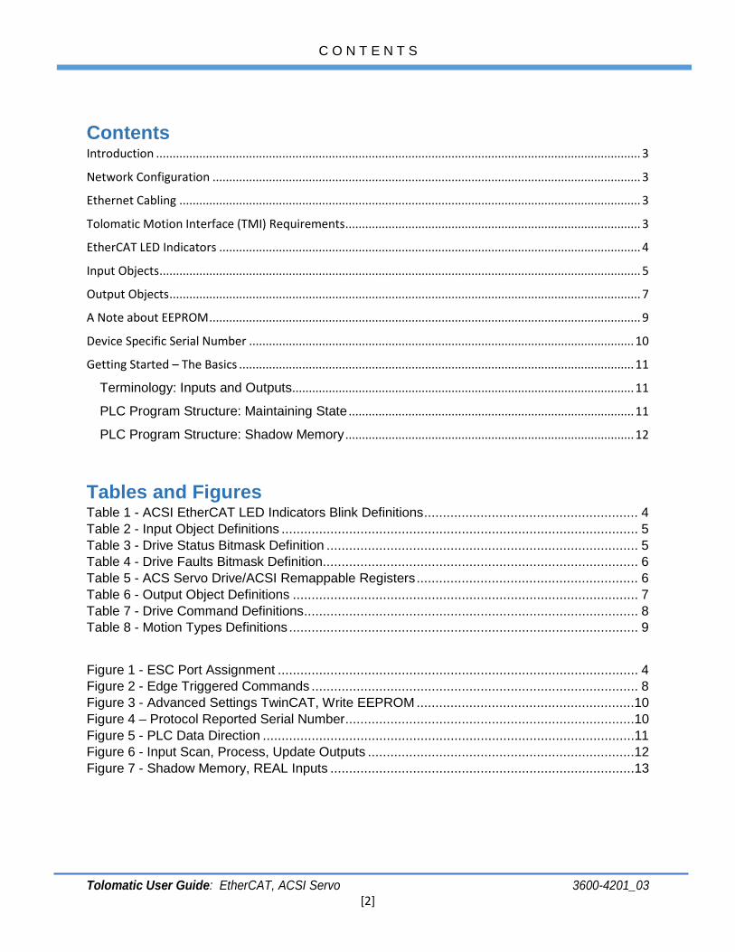
Output Objects The following are output objects, as defined by the ESI file for use with the ACSI Integrated Drive & Controller.
Output Objects Direction (Perspective of PLC)
> Address Type Size Description Units
Output
39 USINT 1 Drive Command
Commands Defined below
40 USINT 1 Move Select
profile index (0 - uses defined target 0 profile, 1-16 uses index profiles defined in TMI)
41 REAL 4 Target0 Position
mm or rotary (as defined by TMI)
45 REAL 4 Target0 Velocity
mm/s or rotary (as defined by TMI)
49 REAL 4 Target0 Acceleration
mm/s² or rotary (as defined by TMI)
53 REAL 4 Target0 Deceleration
mm/s² or rotary (as defined by TMI)
57 REAL 4 Target0 Force
% of Peak Current of Motor (as defined by TMI)
61 UDINT 4 Target0 Motion Type
enumeration (defined below)
65 BITARR32 4 Digital Outputs
bitmask (first 2 bits represent 2 outputs)
Table 6 - Output Object Definitions

O U T P U T O B J E C T S
Tolomatic User Guide: EtherCAT, ACSI Servo 3600-4201_03
[8]
Drive Command Definition Command Description
0 (0x00) Disable 1 (0x01) Enable/Clear Start Motion 3 (0x03) Start Motion 5 (0x05) Home 8 (0x08) Software Stop 17 (0x11) Stop Motion 21 (0x15) Home Here
Table 7 - Drive Command Definitions
Note: Drive Command Processing
The drive processes commands issued over the network in an edge-triggered manner. The drive does not process new commands unless they differ from the previous command. For motion, this means the drive will not make a new move until it detects a new “Start Motion” command. To clear the previous Start Motion command, the PLC program must set the command to something other than Start Motion. “Enable” is typically used. This can be done while the drive is in motion, or in a time-based scheme as long as the drive has sufficient time to detect the transition from Start Motion to Enable (> 2x Scan Rate).
//ENABLE//
//START MOTION//
//ENABLE//
//START MOTION//
//ENABLE//
0
1
0
1
Drive Status:In Motion Bit
Figure 2 - Edge Triggered Commands
O U T P U T O B J E C T S - A N O T E A B O U T E E P R O M
Tolomatic User Guide: EtherCAT, ACSI Servo 3600-4201_03
[9]
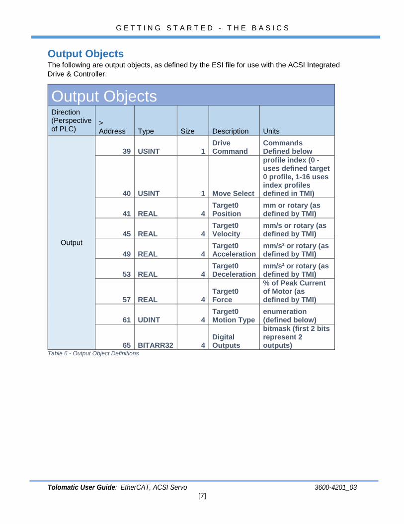
Motion Types Enumeration Name Value Description
Absolute 0 Moves to absolute position defined by Target0 Position using the defined motion profile
Incremental Positive 1 Moves in the positive direction the distance specified by Target0 Position
using the defined motion profile Incremental
Negative 2 Moves in the negative direction the distance specified by Target0 Position using the defined motion profile
Home 5 Executes a home motion using the homing profile defined in TMI
No Action 6 Does not execute motion
Force 9 Press to Target0 Force % defined by motion profile (more complete description available in TMI manual)
Incremental Positive Rotary
11 Moves in the positive direction the distance specified by Target0 Position
at the defined motion profile. If position is commanded past max distance, the current position is reset and the drive is un-homed
Incremental Negative Rotary
12 Moves in the negative direction the distance specified by Target0 Position
using the defined motion profile. If position is commanded past max distance, the current position is reset and the drive is un-homed
Velocity Forward 13 Starts a velocity move in the positive direction at profile velocity and
acceleration (Set Velocity Feed Forward Tuning to 100% in TMI) Velocity Reverse 14 Starts a velocity move in the negative direction at the profile velocity and
acceleration (Set Velocity Feed Forward Tuning to 100% in TMI) Table 8 - Motion Types Definitions
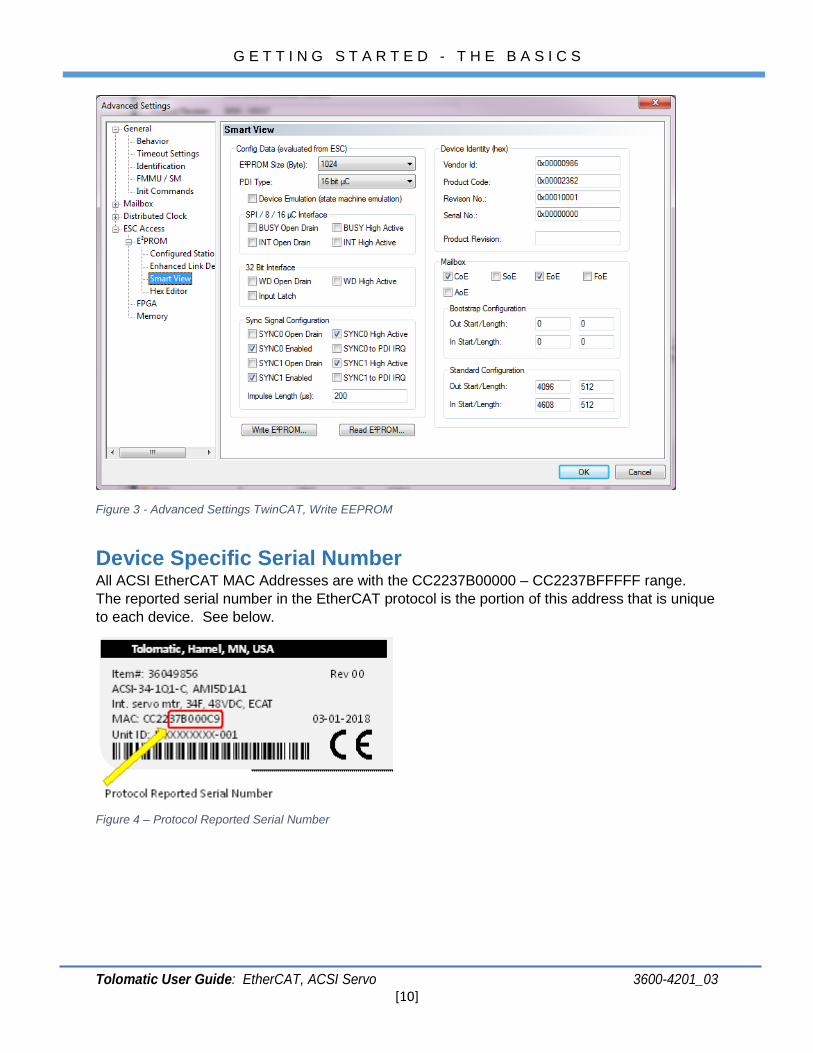
A Note about EEPROM The ACS Drive should be shipped from Tolomatic with the EEPROM already configured. In the event that the drive is not responding or the drive does not go into OP mode, the user may have to update the EEPROM using EtherCAT. In TwinCAT, this is done in the Advanced Settings under the device.
G E T T I N G S T A R T E D - T H E B A S I C S
Tolomatic User Guide: EtherCAT, ACSI Servo 3600-4201_03 [10]
Figure 3 - Advanced Settings TwinCAT, Write EEPROM
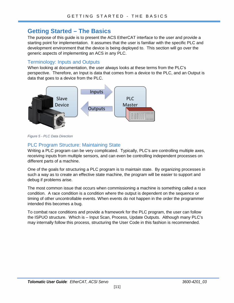
Device Specific Serial Number All ACSI EtherCAT MAC Addresses are with the CC2237B00000 – CC2237BFFFFF range. The reported serial number in the EtherCAT protocol is the portion of this address that is unique to each device. See below.
Figure 4 – Protocol Reported Serial Number
G E T T I N G S T A R T E D - T H E B A S I C S
Tolomatic User Guide: EtherCAT, ACSI Servo 3600-4201_03 [11]
Getting Started – The Basics The purpose of this guide is to present the ACS EtherCAT interface to the user and provide a starting point for implementation. It assumes that the user is familiar with the specific PLC and development environment that the device is being deployed to. This section will go over the generic aspects of implementing an ACS in any PLC.
Terminology: Inputs and Outputs When looking at documentation, the user always looks at these terms from the PLC’s perspective. Therefore, an Input is data that comes from a device to the PLC, and an Output is data that goes to a device from the PLC.
SlaveDevice
PLCMaster
Inputs
Outputs
Figure 5 - PLC Data Direction
PLC Program Structure: Maintaining State Writing a PLC program can be very complicated. Typically, PLC’s are controlling multiple axes, receiving inputs from multiple sensors, and can even be controlling independent processes on different parts of a machine.
One of the goals for structuring a PLC program is to maintain state. By organizing processes in such a way as to create an effective state machine, the program will be easier to support and debug if problems arise.
The most common issue that occurs when commissioning a machine is something called a race condition. A race condition is a condition where the output is dependent on the sequence or timing of other uncontrollable events. When events do not happen in the order the programmer intended this becomes a bug.
To combat race conditions and provide a framework for the PLC program, the user can follow the ISPUO structure. Which is – Input Scan, Process, Update Outputs. Although many PLC’s may internally follow this process, structuring the User Code in this fashion is recommended.
G E T T I N G S T A R T E D - T H E B A S I C S
Tolomatic User Guide: EtherCAT, ACSI Servo 3600-4201_03 [12]
Inputs Scan
Process
Update Outputs
Shad
owM
emor
y
Copy To PLC Memory
Process Inputs, Queue Outputs
Copy From PLC Memory
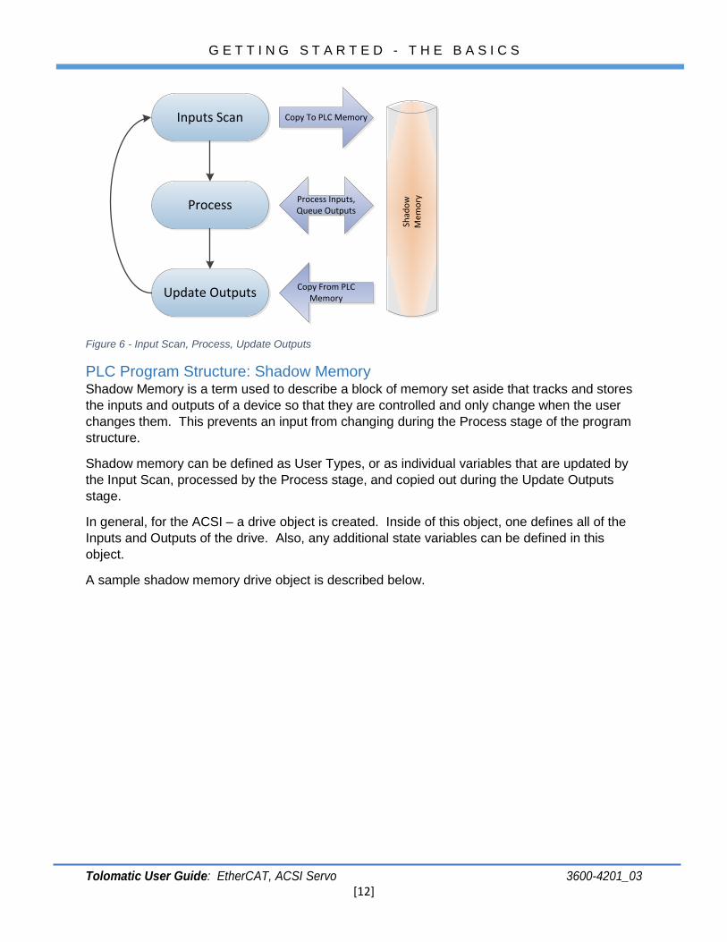
Figure 6 - Input Scan, Process, Update Outputs
PLC Program Structure: Shadow Memory Shadow Memory is a term used to describe a block of memory set aside that tracks and stores the inputs and outputs of a device so that they are controlled and only change when the user changes them. This prevents an input from changing during the Process stage of the program structure.
Shadow memory can be defined as User Types, or as individual variables that are updated by the Input Scan, processed by the Process stage, and copied out during the Update Outputs stage.
In general, for the ACSI – a drive object is created. Inside of this object, one defines all of the Inputs and Outputs of the drive. Also, any additional state variables can be defined in this object.
A sample shadow memory drive object is described below.
G E T T I N G S T A R T E D - T H E B A S I C S
Tolomatic User Guide: EtherCAT, ACSI Servo 3600-4201_03 [13]
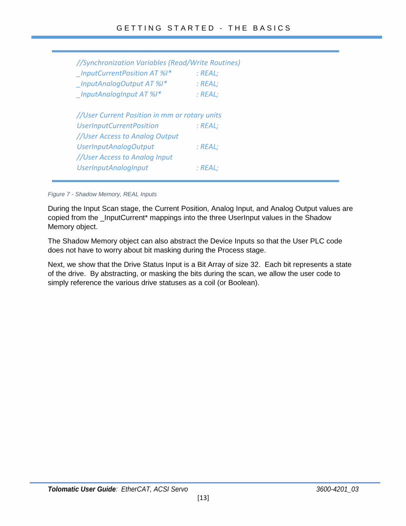
Figure 7 - Shadow Memory, REAL Inputs
During the Input Scan stage, the Current Position, Analog Input, and Analog Output values are copied from the _InputCurrent* mappings into the three UserInput values in the Shadow Memory object.
The Shadow Memory object can also abstract the Device Inputs so that the User PLC code does not have to worry about bit masking during the Process stage.
Next, we show that the Drive Status Input is a Bit Array of size 32. Each bit represents a state of the drive. By abstracting, or masking the bits during the scan, we allow the user code to simply reference the various drive statuses as a coil (or Boolean).
//Synchronization Variables (Read/Write Routines) _InputCurrentPosition AT %I* : REAL; _InputAnalogOutput AT %I* : REAL; _InputAnalogInput AT %I* : REAL; //User Current Position in mm or rotary units
UserInputCurrentPosition : REAL; //User Access to Analog Output UserInputAnalogOutput : REAL; //User Access to Analog Input UserInputAnalogInput : REAL;
G E T T I N G S T A R T E D - T H E B A S I C S
Tolomatic User Guide: EtherCAT, ACSI Servo 3600-4201_03 [14]
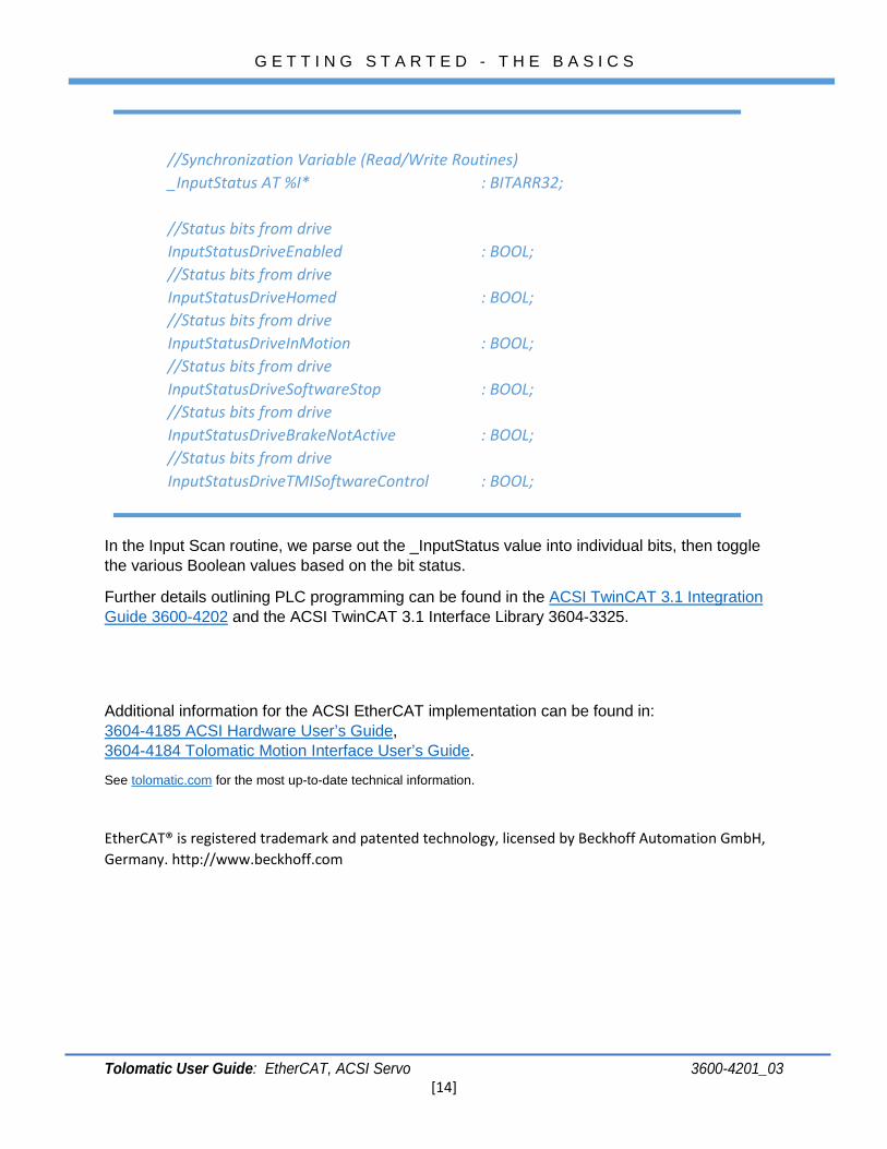
In the Input Scan routine, we parse out the _InputStatus value into individual bits, then toggle the various Boolean values based on the bit status.
Further details outlining PLC programming can be found in the ACSI TwinCAT 3.1 Integration Guide 3600-4202 and the ACSI TwinCAT 3.1 Interface Library 3604-3325.
Additional information for the ACSI EtherCAT implementation can be found in: 3604-4185 ACSI Hardware User’s Guide, 3604-4184 Tolomatic Motion Interface User’s Guide.
See tolomatic.com for the most up-to-date technical information.
EtherCAT® is registered trademark and patented technology, licensed by Beckhoff Automation GmbH, Germany. http://www.beckhoff.com
//Synchronization Variable (Read/Write Routines) _InputStatus AT %I* : BITARR32;
//Status bits from drive
InputStatusDriveEnabled : BOOL; //Status bits from drive InputStatusDriveHomed : BOOL; //Status bits from drive InputStatusDriveInMotion : BOOL; //Status bits from drive InputStatusDriveSoftwareStop : BOOL; //Status bits from drive InputStatusDriveBrakeNotActive : BOOL; //Status bits from drive InputStatusDriveTMISoftwareControl : BOOL;