ETAS RTPC V6.3.7 - User´s Guide · Users should be familiar with the Microsoft Windows XP, Windows...
67
www.etas.com ETAS RTPC V6.3.7 User’s Guide
Transcript of ETAS RTPC V6.3.7 - User´s Guide · Users should be familiar with the Microsoft Windows XP, Windows...

www.etas.com
ETAS RTPC V6.3.7User’s Guide

Copyright
The data in this document may not be altered or amended without special noti-fication from ETAS GmbH. ETAS GmbH undertakes no further obligation in relation to this document. The software described in it can only be used if the customer is in possession of a general license agreement or single license. Using and copying is only allowed in concurrence with the specifications stipulated in the contract.
Under no circumstances may any part of this document be copied, reproduced, transmitted, stored in a retrieval system or translated into another language without the express written permission of ETAS GmbH.
© Copyright 2019 ETAS GmbH, Stuttgart
The names and designations used in this document are trademarks or brands belonging to the respective owners.
V6.3.7 R01 EN - 05.2019

ETAS Contents
Contents
1 Introduction. . . . . . . . . . . . . . . . . . . . . . . . . . . . . . . . . . . . . . . . . . . . . . . . . . . . . . . . . . . 51.1 System Concept. . . . . . . . . . . . . . . . . . . . . . . . . . . . . . . . . . . . . . . . . . . . . . . . . . . . . . . . . . 51.1.1 "LABCAR Test Systems" Use Case . . . . . . . . . . . . . . . . . . . . . . . . . . . . . . . . . 51.1.2 "EVE - Validation of AUTOSAR Software" Use Case. . . . . . . . . . . . . . . . . . . 5
1.2 Target Group. . . . . . . . . . . . . . . . . . . . . . . . . . . . . . . . . . . . . . . . . . . . . . . . . . . . . . . . . . . . . 6
1.3 Data Protection Declaration. . . . . . . . . . . . . . . . . . . . . . . . . . . . . . . . . . . . . . . . . . . . . . . . 61.3.1 Data Processing of ETAS RTPC . . . . . . . . . . . . . . . . . . . . . . . . . . . . . . . . . . . 61.3.2 Data and Data Categories. . . . . . . . . . . . . . . . . . . . . . . . . . . . . . . . . . . . . . . . . 61.3.3 Technical and Organizational Measures . . . . . . . . . . . . . . . . . . . . . . . . . . . . 6
1.4 About This Manual . . . . . . . . . . . . . . . . . . . . . . . . . . . . . . . . . . . . . . . . . . . . . . . . . . . . . . . 71.4.1 Using This Manual . . . . . . . . . . . . . . . . . . . . . . . . . . . . . . . . . . . . . . . . . . . . . . . 7
2 Installation . . . . . . . . . . . . . . . . . . . . . . . . . . . . . . . . . . . . . . . . . . . . . . . . . . . . . . . . . . . 92.1 Delivery Scope . . . . . . . . . . . . . . . . . . . . . . . . . . . . . . . . . . . . . . . . . . . . . . . . . . . . . . . . . . . 9
2.2 System Requirements. . . . . . . . . . . . . . . . . . . . . . . . . . . . . . . . . . . . . . . . . . . . . . . . . . . . . 92.2.1 Hardware Requirements. . . . . . . . . . . . . . . . . . . . . . . . . . . . . . . . . . . . . . . . . 102.2.2 Hardware Support . . . . . . . . . . . . . . . . . . . . . . . . . . . . . . . . . . . . . . . . . . . . . . 102.2.3 Special BIOS Settings . . . . . . . . . . . . . . . . . . . . . . . . . . . . . . . . . . . . . . . . . . . 11
2.3 Installation. . . . . . . . . . . . . . . . . . . . . . . . . . . . . . . . . . . . . . . . . . . . . . . . . . . . . . . . . . . . . . 122.3.1 Installing ETAS RTPC on the Real-Time PC . . . . . . . . . . . . . . . . . . . . . . . . 122.3.2 Installing ETAS RTPC in a Virtual Machine . . . . . . . . . . . . . . . . . . . . . . . . . 142.3.3 Hardware Integration. . . . . . . . . . . . . . . . . . . . . . . . . . . . . . . . . . . . . . . . . . . . 142.3.4 System Configuration . . . . . . . . . . . . . . . . . . . . . . . . . . . . . . . . . . . . . . . . . . . 152.3.5 Licensing . . . . . . . . . . . . . . . . . . . . . . . . . . . . . . . . . . . . . . . . . . . . . . . . . . . . . . 162.3.6 Resetting the Boot Setting . . . . . . . . . . . . . . . . . . . . . . . . . . . . . . . . . . . . . . . 162.3.7 Cloning Installed Versions . . . . . . . . . . . . . . . . . . . . . . . . . . . . . . . . . . . . . . . 172.3.8 RTIO Configuration of the ES1130 . . . . . . . . . . . . . . . . . . . . . . . . . . . . . . . . 192.3.9 Clock Synchronization. . . . . . . . . . . . . . . . . . . . . . . . . . . . . . . . . . . . . . . . . . . 19
2.4 PCI CAN and FlexRay Boards . . . . . . . . . . . . . . . . . . . . . . . . . . . . . . . . . . . . . . . . . . . . . 20
3 Operation. . . . . . . . . . . . . . . . . . . . . . . . . . . . . . . . . . . . . . . . . . . . . . . . . . . . . . . . . . . 213.1 Operating Modes . . . . . . . . . . . . . . . . . . . . . . . . . . . . . . . . . . . . . . . . . . . . . . . . . . . . . . . . 21
3.1.1 "Simulation Controller" Mode . . . . . . . . . . . . . . . . . . . . . . . . . . . . . . . . . . . . . 213.1.2 "Idle/Configuration" Mode . . . . . . . . . . . . . . . . . . . . . . . . . . . . . . . . . . . . . . . 223.1.3 "Ethernet Bridge" Mode . . . . . . . . . . . . . . . . . . . . . . . . . . . . . . . . . . . . . . . . . . 223.1.4 "Power Down" Mode . . . . . . . . . . . . . . . . . . . . . . . . . . . . . . . . . . . . . . . . . . . . 22
3.2 ETAS RTPC in the Experiment Environment LABCAR-EE. . . . . . . . . . . . . . . . . . . . . . 23
3.3 Runtime Traces . . . . . . . . . . . . . . . . . . . . . . . . . . . . . . . . . . . . . . . . . . . . . . . . . . . . . . . . . 24
3.4 CAN Trace . . . . . . . . . . . . . . . . . . . . . . . . . . . . . . . . . . . . . . . . . . . . . . . . . . . . . . . . . . . . . . 26
3.5 Step-by-Step Execution of the Simulation. . . . . . . . . . . . . . . . . . . . . . . . . . . . . . . . . . . 30
3.6 Real-Time Plugins (RT Plugins). . . . . . . . . . . . . . . . . . . . . . . . . . . . . . . . . . . . . . . . . . . . 323.6.1 Preparation of the LABCAR-OPERATOR Project . . . . . . . . . . . . . . . . . . . . 323.6.2 The Plugin Files . . . . . . . . . . . . . . . . . . . . . . . . . . . . . . . . . . . . . . . . . . . . . . . . 333.6.3 Special Preprocessor Directives . . . . . . . . . . . . . . . . . . . . . . . . . . . . . . . . . . 343.6.4 Templates and Examples . . . . . . . . . . . . . . . . . . . . . . . . . . . . . . . . . . . . . . . . 353.6.5 Procedure . . . . . . . . . . . . . . . . . . . . . . . . . . . . . . . . . . . . . . . . . . . . . . . . . . . . . 35
3.7 CPU Core Load . . . . . . . . . . . . . . . . . . . . . . . . . . . . . . . . . . . . . . . . . . . . . . . . . . . . . . . . . . 36
ETAS RTPC V6.3.7 - User’s Guide 3

ETAS Contents
3.8 Benchmark Indicator. . . . . . . . . . . . . . . . . . . . . . . . . . . . . . . . . . . . . . . . . . . . . . . . . . . . . 37
3.9 Testing Hardware Performance with "cyclictest" . . . . . . . . . . . . . . . . . . . . . . . . . . . . 37
3.10 CAN/CANFD-Abstraction and LIN-Abstraction . . . . . . . . . . . . . . . . . . . . . . . . . . . . . . 393.10.1 General Functional Principle . . . . . . . . . . . . . . . . . . . . . . . . . . . . . . . . . . . . . 393.10.2 Abstraction of the Bus Interfaces During the Build Process . . . . . . . . . . 403.10.3 Converting the Channel Description into Concrete Bus Interfaces at Runti-
me . . . . . . . . . . . . . . . . . . . . . . . . . . . . . . . . . . . . . . . . . . . . . . . . . . . . . . . . . . . .413.10.4 Template for a Channel Configuration. . . . . . . . . . . . . . . . . . . . . . . . . . . . . 41
4 Configuration . . . . . . . . . . . . . . . . . . . . . . . . . . . . . . . . . . . . . . . . . . . . . . . . . . . . . . . 444.1 Applications . . . . . . . . . . . . . . . . . . . . . . . . . . . . . . . . . . . . . . . . . . . . . . . . . . . . . . . . . . . . 44
4.1.1 Model-in-the-Loop (MiL) . . . . . . . . . . . . . . . . . . . . . . . . . . . . . . . . . . . . . . . . . 444.1.2 Hardware-in-the-Loop (HiL) . . . . . . . . . . . . . . . . . . . . . . . . . . . . . . . . . . . . . . 444.1.3 Hardware-in-the-Loop with Measuring and Calibration Access (M&C) . 454.1.4 Hardware-in-the-Loop with Load and Error Simulation. . . . . . . . . . . . . . . 454.1.5 Massive I/O . . . . . . . . . . . . . . . . . . . . . . . . . . . . . . . . . . . . . . . . . . . . . . . . . . . . 45
4.2 The Web Interface . . . . . . . . . . . . . . . . . . . . . . . . . . . . . . . . . . . . . . . . . . . . . . . . . . . . . . . 464.2.1 Access to the Web Interface . . . . . . . . . . . . . . . . . . . . . . . . . . . . . . . . . . . . . 464.2.2 Navigation . . . . . . . . . . . . . . . . . . . . . . . . . . . . . . . . . . . . . . . . . . . . . . . . . . . . . 474.2.3 Functions . . . . . . . . . . . . . . . . . . . . . . . . . . . . . . . . . . . . . . . . . . . . . . . . . . . . . . 48
5 Troubleshooting . . . . . . . . . . . . . . . . . . . . . . . . . . . . . . . . . . . . . . . . . . . . . . . . . . . . . 59
6 Glossary. . . . . . . . . . . . . . . . . . . . . . . . . . . . . . . . . . . . . . . . . . . . . . . . . . . . . . . . . . . . 63
7 ETAS Contact Addresses . . . . . . . . . . . . . . . . . . . . . . . . . . . . . . . . . . . . . . . . . . . . . 65
Index . . . . . . . . . . . . . . . . . . . . . . . . . . . . . . . . . . . . . . . . . . . . . . . . . . . . . . . . . . . . . . 66
ETAS RTPC V6.3.7 - User’s Guide 4

ETAS Introduction
1 IntroductionETAS RTPC transforms your standard PC into a high-performance simulation target. As ETAS RTPC consistently uses standard commercial components, you benefit from the continuous development of PC technology with regard to the available processing power and communication bandwidth. ETAS RTPC uses all processor cores of state-of-the-art Intel multi-core processors.
1.1 System Concept
1.1.1 "LABCAR Test Systems" Use CaseOnce the ETAS RTPC software has been installed, your standard PC is trans-ferred into a real-time PC for LABCAR test systems.
Fig. 1-1 shows the hardware setup of a ETAS RTPC system. The real-time PC is connected to the user PC via Ethernet and can be selected as a simulation tar-get in the LABCAR software.
Fig. 1-1 RTPC System
The real-time PC is controlled entirely from the user PC via an intuitive Web interface. Keyboard and monitor are not needed (apart from during installa-tion).
The I/O hardware communicates with the real-time PC via Ethernet – the I/O data gets to its target deterministically and securely via a highly optimized point-to-point connection.
A PC with ETAS RTPC is also used as a simulation PC in the open and scalable ETAS HiL system PT-LABCAR which is designed for closed-loop tests of ECUs in the drive train area.
1.1.2 "EVE - Validation of AUTOSAR Software" Use CaseISOLAR-EVE allows to validate AUTOSAR compliant software on different plat-forms. ETAS RTPC is one of those platforms.
ETAS RTPC allows to create and operate a so called VECU (virtual electronic control unit) with access to external hardware resources like CAN, DIO, ADC, PWM.
ISOLAR-EVE runs on a user PC and operates the real-time PC mainly via auto-mation interfaces in order to build the executable and to control the execution.
Real-Time PC ES4100ES4105ES4300
ES1130
I/OHardware
User PC
LABCARSoftware
Ethernet(Eth0)
Real-Time Ethernet(Eth1)
PCISerial I/O
ETAS RTPC V6.3.7 - User’s Guide 5

ETAS Introduction
General configuration like licensing and monitoring may be done via ETAS RTPC's intuitive Web interface.
1.2 Target GroupThis manual addresses qualified personnel working in the fields of automobile control unit development and calibration. Specialized knowledge in the areas of measurement and control unit technology is required.
Users should be familiar with the Microsoft Windows XP, Windows Vista, or Windows 7 operating system. Furthermore, the users should be familiar with the Windows file storage system, especially the connections between files and directories.
The users have to know how to use the basic functions of the Windows File Manager and Program Manager or the Windows Explorer, respectively, and they should be familiar with the "drag-and-drop" functionality.
ISOLAR-EVE users not yet familiar with automotive software descriptions based on the AUTOSAR framework are advised to get a suitable training upfront.
Knowledge about the general features and operation of Eclipse based software products will be beneficial but is not mandatory.
1.3 Data Protection Declaration
1.3.1 Data Processing of ETAS RTPCPlease note that personal or person-related data or data categories are pro-cessed when using ETAS RTPC.
As the manufacturer, ETAS GmbH is not liable for any mishandling of this data.
1.3.2 Data and Data CategoriesWhen using the ETAS License Manager in combination with user-based licenses, particularly the following personal or person-related data or data cat-egories are recorded for the purposes of license management:
Communication data: IP addressUser data: User ID
1.3.3 Technical and Organizational MeasuresETAS RTPC does not encrypt the collected personal or person-related data.
Please ensure the data security of the recorded data by suitable technical or organizational measures of your IT system, e.g. by classical anti-theft and access protection on the hardware.
TIPThe purchaser of ETAS RTPC is responsible for the legal conformity of pro-cessing the data in accordance with Article 4 No. 7 of the General Data Pro-tection Regulation (GDPR).
ETAS RTPC V6.3.7 - User’s Guide 6

ETAS Introduction
1.4 About This ManualThis manual is intended, on the one hand, for all users who install, maintain and uninstall ETAS RTPC on the target PC, and, on the other, for system administra-tors who make ETAS RTPC available on a file server for installation via the net-work. It provides important information on the delivery scope, hardware and software requirements for single station and network installation as well as on how to prepare the installation.
This manual consists of the following chapters:
• “Introduction” on page 5
This chapter• “Installation” on page 9
This chapter contains information on system requirements and on how to install ETAS RTPC including details of the environment configuration.
• “Operation” on page 21
This chapter describes the operating modes of ETAS RTPC, as well as the creation and migration of projects for ETAS RTPC.
• “Configuration” on page 44
This chapter describes the uses and configuration of ETAS RTPC with the web interface.
• “Troubleshooting” on page 59
This chapter presents the description of some typical problems with possible solutions.
• “Glossary” on page 63
1.4.1 Using This Manual
1.4.1.1 Representation of InformationAll activities to be carried out by the user are shown in what we call a "Use-Case" format, i.e. the target to be achieved is defined briefly in the title and the individual steps necessary to achieve this target are then listed. The informa-tion is displayed as follows:
Target definitionAny introductory information...
1. Step 1
Possibly an explanation of step 1...
2. Step 2
Possibly an explanation of step 2...
Any concluding remarks...
Concrete example:
To create a new fileIf you want to create a new file, no other file may be open.
1. Select File → New.
The "Create file" dialog box appears.
ETAS RTPC V6.3.7 - User’s Guide 7

ETAS Introduction
2. Enter a name for the file in the "File name" field.
The file name must not exceed 8 characters.
3. Click OK.
The new file is created and saved under the name specified. You can now work with the file.
1.4.1.2 Typographic ConventionsThe following typographic conventions are used:
Important notes for the user are shown as follows:
Select File → Open. Menu commands are shown in boldface.Click OK. Buttons are shown in boldfacePress <ENTER>. Keyboard commands are shown in
angled brackets in block capitals.The "Open File" dialog box appears.
Names of program windows, dialog boxes, fields etc. are shown in quotation marks.
Select the file setup.exe. Text in drop-down lists, program code, as well as path and file names are shown in the Courier font.
A conversion between the file types logical and arithmetic is not possible.
Content markings and newly introduced terms are shown in italics
TIPImportant note for the user.
ETAS RTPC V6.3.7 - User’s Guide 8

ETAS Installation
2 InstallationThis chapter includes information on the following topics:
• “Delivery Scope” on page 9
• “System Requirements” on page 9
– “Hardware Requirements” on page 10– “Special BIOS Settings” on page 11
• “Installation” on page 12
– “Installing ETAS RTPC on the Real-Time PC” on page 12– “Installing ETAS RTPC in a Virtual Machine” on page 14– “Hardware Integration” on page 14– “System Configuration” on page 15– “Licensing” on page 16– “Resetting the Boot Setting” on page 16– “Cloning Installed Versions” on page 17– “RTIO Configuration of the ES1130” on page 19– “Clock Synchronization” on page 19
• “PCI CAN and FlexRay Boards” on page 20
2.1 Delivery Scope The delivery scope of ETAS RTPC V6.3.7 includes
• ETAS RTPC Software DVD
• This User's Guide
• Possibly a PC from ETAS
2.2 System RequirementsYou need the following to install and run the ETAS RTPC software:
• ETAS RTPC Software CD
• A ETAS RTPC software license
• Suitable PC hardware (see "“Hardware Requirements” on page 10")
• Ethernet crossover cable (2x RJ45 socket) for the connection between the real-time PC and user PC
ETAS RTPC V6.3.7 - User’s Guide 9

ETAS Installation
2.2.1 Hardware RequirementsETAS RTPC is compatible with most standard PCs. To run the software, the following requirements must be fulfilled:
For more precise details on the compatibility of PCs made by different manu-facturers, refer to the compatibility list (http://192.168.40.14/documentation/).
2.2.2 Hardware SupportETAS RTPC supports a maximum number of hardware connections related to the ES5300 series.
Processor Intel Xeon familyIntel Core i familyIntel Core 2 family (Duo and Quad)
Ethernet adapter for the connection to the user PC
All Ethernet adapters supported by Linux kernel 3.18
Ethernet adapter for the connection to the ES1130
All Ethernet adapters supported by Linux kernel 3.18e.g. - Intel PRO/100 card S, revision 12 (0C) or later- Intel PRO/1000 family- Intel PRO/1000 PT Quad Port Server Adapter- Intel Gigabit CT Desktop Adapter
RAM Min. 4 GB, 8 GB and more recommendedHard disk IDE or SATA, min. 250 GBGraphic VGA-compatibleMonitor Is only required for basic installationKeyboard PS/2 or USB, is only required for basic installationCD-ROM drive IDE, SATA or USB, is only required for basic installa-
tion (bootable)Operating system Not necessary
TIPDuring ETAS RTPC operation, success or error messages are emitted in theform of sound. If your PC does not have an output device for acoustic signals,you can access information on the current status via the web interface (seesection “The Web Interface” on page 46).
TIPBefore you design or configure a system with the specified maximum num-ber of hardware connections, get in touch with your ETAS contact person.The ETAS contact person supports you to select the individual hardware.
ETAS RTPC V6.3.7 - User’s Guide 10

ETAS Installation
The following table contains the maximum number of the hardware connec-tions:
If you extend the RS232/RS485 port number to 16, a change of the port order is possible. If you use these ports, verify the hardware configuration and change it accordingly.
2.2.3 Special BIOS Settings
2.2.3.1 Boot SettingsTo ensure the installation from CD-ROM works, the system’s BIOS has to be configured so that the PC boots from the CD-ROM ("primary boot device = CD-ROM"). If you want to use the PC later without a keyboard, you also have to specify this setting ("no halt on keyboard"). The names of the settings in brackets may vary - for more details, refer to your PC’s User’s Guide.
2.2.3.2 Hyper-ThreadingThe usage of hyper-threading has an impact on the real-time performance of the used real-time PC as two hyper-threaded cores share some CPU resources, e.g. the FPU and the ALU are typically shared among two hyper-threaded cores.
This leads to influences in the execution of the code running on the hyper-threaded cores as one hyper-threaded core may have to wait for the other hyper-threaded core to release a shared CPU resource.
If you are running in issues getting real-time violations it might be helpful to deactivate hyper-threading in the BIOS settings of the used real-time PC. Espe-cially if you are running simulation models with very fast cycle times (faster than 100 µs), it is recommended to disable hyper-threading completely as the additional time for waiting for CPU resources may break the cycle times.
However there are some situations where hyper-threading can be used without getting real-time violations. In these cases you may benefit from the additional CPU power.
Typical situations for this are setups that are using simulation models with moderate cycle times (slower than 500 µs) or also for real-time PCs that are used as build machines only. In these situations the higher overall computation power can be used beneficially.
Hardware Maximum NumberCAN Boards 32Network Ports 32FlexRay Boards 8RS232 Ports/RS485 Ports
16
TIPFor details of the ETAS PC hardware BIOS settings, refer to http://192.168.40.14/documentation/.
ETAS RTPC V6.3.7 - User’s Guide 11

ETAS Installation
2.3 InstallationThe installation of ETAS RTPC is divided into four parts which are each described in the sections below:
• “Installing ETAS RTPC on the Real-Time PC” on page 12
• “Installing ETAS RTPC in a Virtual Machine” on page 14
• “Hardware Integration” on page 14
• “System Configuration” on page 15
• “Licensing” on page 16
• “Resetting the Boot Setting” on page 16
• “Cloning Installed Versions” on page 17
• “RTIO Configuration of the ES1130” on page 19
• “Clock Synchronization” on page 19
2.3.1 Installing ETAS RTPC on the Real-Time PCIf ETAS RTPC has already been installed by ETAS, please continue with the next section “Hardware Integration” on page 14.
To install ETAS RTPC on the real-time PC1. Connect the monitor and keyboard to the PC hardware.
2. Switch the PC and the monitor on.
3. Insert the ETAS RTPC Software DVD into the real-time PC’s DVD drive.
4. In the start screen select the desired option (default: ETAS RTPC Vx.y.z – Standard Install).
5. Wait until the ETAS RTPC installation dialog box is displayed.
6. Select the option [Install RTPC software] using the cursor keys.
7. Press <ENTER>.
TIPETAS also offers ETAS RTPC as a preinstalled version on PC hardwarerecommended and tested by ETAS. In this case, please start by reading thesection “Hardware Integration” on page 14.
TIPWith this option the file system "ext3" is installed – if youhave to be compatible with ETAS RTPC versions beforeV5.1.0. select the "Install for parallel use with RTPC versionsbefore V5.1.0" option.
TIPAll data on the hard disk is deleted by the ETAS RTPC instal-lation!
ETAS RTPC V6.3.7 - User’s Guide 12

ETAS Installation
8. Confirm the warning by selecting the option[Yes, continue with installation].
9. Wait until the ETAS RTPC installation has been completed (takes about 5 minutes).
10.Remove the ETAS RTPC Software DVD.
11.Select the option [Reboot].
The PC reboots.
12.Wait until the PC plays an ascending sequence of notes.
ETAS RTPC has been installed successfully.
13.Shut down the PC by quickly pressing the on/off switch.
After just a few seconds, the PC plays a descending sequence of notes and shuts down.
This indicates that ETAS RTPC has been shut down correctly and can be disconnected from the mains.
For more details on these acoustic signals, refer to the chapter “Operation” on page 21.
14.Remove monitor and keyboard (see “Special BIOS Settings” on page 11).
TIPETAS RTPC uses a robust file system, but hardware andsoftware can still be damaged when powered off withoutshutting down or during a sudden voltage drop. ETAS thusrecommends shutting down ETAS RTPC by briefly pressingthe on/off switch to avoid these problems.
ETAS RTPC V6.3.7 - User’s Guide 13

ETAS Installation
To test the reachability of ETAS RTPC1. Toggle to the host.
2. Select Run from the Start menu.
3. Enter "cmd".
The command prompt opens.
4. Enter the following:ping 192.168.40.14
5. Alternatively, you can open the web interface (http://192.168.40.14) in your browser.
2.3.2 Installing ETAS RTPC in a Virtual MachineThe ETAS RTPC software can be installed in a virtual machine. Use the installa-tion image for this. The virtual machine must be configured according to the system requirements of the ETAS RTPC (see “System Requirements” on page 9"). For the configuration and installation of the virtual machine, please refer to the instructions of the corresponding tool.
To operate the ETAS RTPC in a virtual machine, ETAS recommends the use of a "host-only" interface as network interface eth0. The steps for the configura-tion of such a network interface can be found in the documentation of the cor-responding tool.
2.3.3 Hardware IntegrationThis section describes the integration of the real-time PC into a Hardware-in-the-Loop test system (HiL). Other configurations, such as Model-in-the-Loop or HiL system with measuring and calibration access, are described in the section “Applications” on page 44.
ETAS RTPC uses the identifier Eth0 (Host) for the onboard Ethernet interface – the Ethernet board has the identifier Eth1 (HW).
To connect the user PC and the ES11301. Connect the real-time PC to the experimental target interface
of the user PC using the onboard Ethernet interface (Eth0) with a crossover cable.
TIPCrossover cables have crossover connections and are oftenindicated on one or both ends with yellow or orange connec-tors.
ETAS RTPC V6.3.7 - User’s Guide 14

ETAS Installation
2. Connect the real-time PC to the ES1130 Simulation Controller Board using the Ethernet interface (Eth1). The ETAS CBE100.1 cable (for ES1130.2 and ES1130.3) or K107 (for ES1130.1) can be used for this connection.
2.3.4 System Configuration ETAS RTPC is easy to configure from the user PC via a Web browser (e.g. Inter-net Explorer or Mozilla Firefox) – the configuration dialog can be accessed via the IP address 192.168.40.14.
Carry out the steps described below to configure ETAS RTPC for Hardware-in-the-Loop tests (HiL). For more details on configuration modes refer to the sec-tion “Applications” on page 44.
To open the configuration dialog1. Launch the real-time PC by pressing the on/off switch on the
front.
2. Switch the chassis with the I/O hardware on.
3. Wait a few seconds until you hear the ascending sequence of notes.
4. Launch a Web browser on the user PC.
5. Invoke the URL http://192.168.40.14.
The ETAS RTPC configuration dialog opens.
The simulation controller has to be stopped to configure the ETAS RTPC Soft-ware (see “"Simulation Controller" Mode” on page 21).
To stop the simulation controller1. Click the Stop Simulation Controller button.
2. Click the Main Page link.
To run the configuration1. Click the Configure ETAS RTPC link.
2. Click the Autoconfigure button.
The autoconfiguration is run and the result is set in the "RTP-C_USAGE_ETH1" box.
To restart the simulation controller1. Click the Main Page link.
2. Click the Simulation Controller link.
TIPYou can also assign this IP address an alias which is easierto remember – for more details refer to the section “Accessto the Web Interface” on page 46.
TIPAs long as the simulation controller is running, the Main Page link is inactive!
ETAS RTPC V6.3.7 - User’s Guide 15

ETAS Installation
3. Click the Start Simulation Controller button.
When you hear the ascending sequence of notes, the simula-tion controller is active again.
The configuration for HiL mode has now been carried out successfully. For more details on other configuration modes refer to the section “Troubleshoot-ing” on page 59.
2.3.5 Licensing To operate ETAS RTPC V6.3.7, you require a license which can be obtained in the form of a license file from the ETAS License Portal. For more details, please refer to the manuals "LABCAR-OPERATOR V5.4.9 - Getting Started" or "ETAS ISOLAR-EVE V3.2 - Installation Guide for Tooling PC".or "COSYMV2.1.0 - Instal-lation and Administration Guide".
License Versions • RTPC_EVE
To execute ISOLAR-EVE projects• LCS_RTPC_RT
To execute LABCAR-OPERATOR projects in real time• COSYM_RT
For the Build process of a COSYM project and its real-time execution• LCS_RTPC_OLC
When running LABCAR-OPERATOR projects and COSYM projects, the minimum period duration is 200 ms.
2.3.6 Resetting the Boot SettingIf there are problems when changing boot settings (e.g. after repartitioning), these settings can be reset.
To reset boot settings1. Select Main Page >> Configuration.
TIPIf instead you hear the sequence of error notes, the simula-tion controller could not be started. For more details refer tothe chapter “Troubleshooting” on page 59.
TIPThe license for ETAS RTPC is not installed using the ETAS License Manager– as described above – but in the web interface (see “License Management”on page 57).
TIPNo license is required for the Build process of a LABCAR-OPERATOR project!
ETAS RTPC V6.3.7 - User’s Guide 16

ETAS Installation
2. Go to the "System Boot Settings" section.
3. Select a version
4. Click Set Boot Version.
5. Reboot the system with Reboot System.
2.3.7 Cloning Installed VersionsYou can clone versions of ETAS RTPC that have already been installed by gen-erating an installable file (*.tgz) and downloading this file to your operating PC.
To clone a version1. Select Main Page >> Installation / Update >> Clone Installed
Version.
2. Select one of the installed versions.
3. Enter a name for the clone to be created.
TIPThe currently active version cannot be cloned!
ETAS RTPC V6.3.7 - User’s Guide 17

ETAS Installation
4. Click Generate Clone Image.
The procedure is started and the progress displayed in the web interface.
Once the procedure has been completed, you can download the clone to use on your operating PC.
To download a clone1. Click the Return to Installation / Update link.
2. Go to "Download Software Image".
3. Select the version just created.
4. Click Download.
A download dialog box opens in which you can save this file.
5. If you want to delete this file from your real-time PC, select the clone under "Delete Installed Software Images".
ETAS RTPC V6.3.7 - User’s Guide 18

ETAS Installation
6. Click Delete.
The file is deleted from your real-time PC.
2.3.8 RTIO Configuration of the ES1130In the case of an ES1130 which is logically connected after a real-time PC, com-munication between ETAS RTPC and the ES1130 takes place synchronously to a selectable task. This selection is made in LABCAR-RTC (RTIO) in the "Globals" tab of the ES1130 ("Synchron Task").
The communication between ETAS RTPC and ES1130 is optimized to this task. The best results are obtained when the simulation model and the periodic hard-ware accesses run in exactly one task ("TaskDVEModel").
2.3.9 Clock SynchronizationTo synchronize the time on the user PC and the real-time PC, you can activate the NTP1 server integrated in Windows.
Activation takes place by making entries in the Windows registry – you will find the file for setting the relevant keys via the web interface at
http://192.168.40.14/tools/NTP/NTP-LocalParameter.regThis configures the Windows service "ws32time" – the server must be rebooted after the keys have been modified.
To reboot the NTP server1. Select Control Panel → Administrative Tools → Services.
2. Select the "Windows Time" service.
3. Open the shortcut menu by pressing the right-hand mouse but-ton.
1.Network Time Protocol
ETAS RTPC V6.3.7 - User’s Guide 19

ETAS Installation
4. Select Restart.
In the web interface it is possible to carry out an ad hoc synchronization of real-time PCclock and host clock (see “Clock Synchronization” on page 54).
2.4 PCI CAN and FlexRay BoardsFor communication between the model and the ECU, you can purchase CAN and FlexRay boards for the ETAS real-time PC.
TIPPlease note that when the service has been rebooted, it can take a few min-utes until the time is precise enough to be made available to other clients.
ETAS RTPC V6.3.7 - User’s Guide 20

ETAS Operation
3 OperationThis chapter includes information on working with ETAS RTPC V6.3.7.
The individual sections are:
• “Operating Modes” on page 21
• “ETAS RTPC in the Experiment Environment LABCAR-EE” on page 23
• “Runtime Traces” on page 24
• “CAN Trace” on page 26
• “Step-by-Step Execution of the Simulation” on page 30
• “Real-Time Plugins (RT Plugins)” on page 32
• “CPU Core Load” on page 36
• “Benchmark Indicator” on page 37
• “Testing Hardware Performance with "cyclictest"” on page 37
3.1 Operating ModesETAS RTPC V6.3.7 has four operating modes, one of which is always active:
• Simulation Controller
• Idle/Configuration
• Ethernet Bridge
• Power Down
Use the Web interface to configure which operating mode is to be activated when the real-time PC is switched on (see “RTPC_POWER_UP_MODE” on page 51).
3.1.1 "Simulation Controller" ModeThe "Simulation Controller" mode is used to run real-time models. An ascending sequence of notes indicates that the simulation controller has been started successfully.
The simulation controller is activated automatically by default when the real-time PC is powered up.
Eight identically pitched notes indicate that the simulation controller cannot be started because of a configuration problem.
In this case, ETAS RTPC is automatically set to "Idle/Configuration" mode (see “"Idle/Configuration" Mode” on page 22).
ETAS RTPC V6.3.7 - User’s Guide 21

ETAS Operation
Possible causes of error can be found in the chapter “Troubleshooting” on page 59.
3.1.2 "Idle/Configuration" ModeThe "Idle/Configuration" mode is used to configure ETAS RTPC and to update the software (Update). ETAS RTPC cannot run real-time models in this mode.
3.1.3 "Ethernet Bridge" Mode This mode establishes a transparent connection between the two Ethernet interfaces Eth0 and Ethn. This connection enables the user to access the ES1130 Simulation Controller Board directly from the user PC; manual exchanging of Ethernet cables is thus unnecessary.
The "Ethernet Bridge" mode is activated automatically for the firmware update of the I/O hardware (HSP or LABCAR firmware update).
3.1.4 "Power Down" ModeThe "Power Down" operating mode is activated either by quickly pressing the on/off switch on the front of the real-time PC or via the Web interface. ETAS RTPC shuts down the system, plays a sequence of notes (four descending notes) and switches the real-time PC off.
TIPIn a LABCAR system a VMEbus reset takes place every time the simulationcontroller is started!
TIPThe "Ethernet Bridge" mode can be configured separately for each "Ethn" port!
Real-Time PCES4100ES4105ES4300
ES1130
I/OHardware
User PC
LABCARSoftware
Eth0 Eth1EthernetBridge
ETAS RTPC V6.3.7 - User’s Guide 22

ETAS Operation
The real-time PC can then be disconnected from the mains.
3.2 ETAS RTPC in the Experiment Environment LABCAR-EEThe experiment environment LABCAR-EE contains a range of instruments that enable access to ETAS RTPC.
These are contained in the LABCAR-EE window "Instruments" in the "LABCAR Instruments" group. They can be dragged into the main workspace from there in the usual manner ("Instrumentation" tab).
These are:
• RTPC State
A running real-time PC is indicated by a green LED• RTPC Web Interface Normal
This instrument contains the complete representation of the web inter-face as in the HTML browser
• RTPC Web Interface Small
This instrument enables the simulation controller to be started (or restarted) and stopped
• RTPC Trace Start
This is used to start an RTPC trace. The files (and the access to them) are described in the section “Runtime Traces” on page 24.
TIPETAS RTPC uses a robust file system, but hardware and software can still bedamaged when powered off without shutting down or during a sudden volt-age drop. ETAS thus recommends shutting down ETAS RTPC by brieflypressing the on/off switch to avoid these problems.
ETAS RTPC V6.3.7 - User’s Guide 23
ETAS Operation
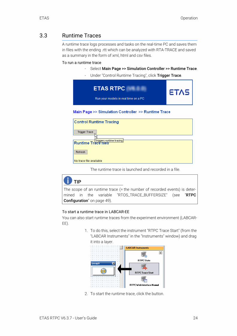
3.3 Runtime TracesA runtime trace logs processes and tasks on the real-time PC and saves them in files with the ending .rtt which can be analyzed with RTA-TRACE and saved as a summary in the form of xml, html and csv files.
To run a runtime trace- Select Main Page >> Simulation Controller >> Runtime Trace.
- Under "Control Runtime Tracing", click Trigger Trace.
The runtime trace is launched and recorded in a file.
To start a runtime trace in LABCAR-EEYou can also start runtime traces from the experiment environment (LABCAR-EE).
1. To do this, select the instrument "RTPC Trace Start" (from the "LABCAR Instruments" in the "Instruments" window) and drag it into a layer.
2. To start the runtime trace, click the button.
TIPThe scope of an runtime trace (= the number of recorded events) is deter-mined in the variable "RTOS_TRACE_BUFFERSIZE" (see “RTPCConfiguration” on page 49).
ETAS RTPC V6.3.7 - User’s Guide 24

ETAS Operation
To open a file with runtime traceThe files with the results of a runtime trace are accessible at the same point:
1. Select a format next to the entry for the relevant file.
Depending on the format selected, the file is opened or a dialog box for saving the file is opened.
2. To display the HTML file of an RTPC trace, click the file ending in the "Type" column.
The file opens in the browser.
ETAS RTPC V6.3.7 - User’s Guide 25

ETAS Operation
The columns have the following meaning:
- Id: the internal ID of the process- Calls: number of calls (while the trace was active)- RTmin, RTavg, RTmax: minimum, average and maximum
runtime of the relevant process.3. You can also download all displayed files of a specific type as
a ZIP archive. Click the relevant link in the "Download all ..." line.
3.4 CAN TraceThe CAN trace functionality enables CAN traffic to and from the IXXAT CAN cards to be monitored – the content of the CAN messages (send and receive) is transferred to a host PC as a UDP/IP stream.
For this purpose, you need a UDP monitor on your host PC, such as Netcat for Windows. The CAN trace is then started in the web interface (see “To start CAN trace in the web interface” on page 26).
Another possibility is to use the perl script provided, labcar-rtpc-can-trace.pl (select CAN Trace and click Help), with which the CAN trace is acti-vated and the data output in a window of the command prompt.
To start CAN trace in the web interface1. Launch the simulation controller in the web interface of ETAS
RTPC.
2. Download your project (in the experiment environment).
3. Start the simulation.
4. Toggle to the ETAS RTPC web interface.
When the simulation controller is running, the Main Page >> Simulation Controller page is displayed.
5. Select CAN Trace.
6. Enter the following data:
- IP AddressThe IP address to which the stream is to be sent.
- UDP PortThe UDP port to which the stream is to be sent (see “port=n” on page 28).
- Ctrl MaskThe bit mask for selecting the board and the relevant con-troller (see “ctrlmask=n” on page 28).
ETAS RTPC V6.3.7 - User’s Guide 26

ETAS Operation
7. Stream output mode
Currently, only "ascii" is possible.
8. Click Start Tracing to send the HTTP request created with these arguments
http://192.168.40.14/cgi-bin/can-trace? cmd=start&ipaddr=192.168.40.240&port=4000&ctrl-mask=0xffff
to the real-time PC.
9. If you would like to filter specific CAN-IDs, you can do so under "CAN-Trace Filter".
10.To end, click Stop Tracing.
The Arguments of the CGI ScriptThis section describes the arguments possible for the "can-trace" CGI script for running an HTTP request.
• cmd=[start|stop|status]
The command to be run – this argument is mandatory.– cmd=start
Starts the CAN trace – other arguments must be specified.– cmd=stop
Stops the CAN trace – other arguments are not necessary.– cmd=status
Outputs the current status of the CAN trace as a text
ETAS RTPC V6.3.7 - User’s Guide 27

ETAS Operation
• format=[html|text]
The output format – "HTML" (default) or "Text" are possible. Specifying this argument is optional.
• ipaddr=a.b.c.d
The IP address (in dotted-decimal notation) to which the UDP messages are to be sent. If no value is specified, the IP address of the caller is used.
• port=n
The UDP port to which the UDP messages are to be sent. This port must be queried from the UDP monitor (= the counterpart). A port must be specified.
• ctrlmask=n
The bit mask for selecting boards (and the controller on them), whose traffic is to be transferred. A unique bit is assigned to every controller on each CAN board; calculation takes place according to the formula:
1 << (2 * board number + controller number)where "board number" can have values between 0 and n, "controller number" 0 or 1.The following table once more illustrates the assignment between board and controller and the relevant bits.
The width of the register is 32 bits; 8 CAN boards (= 16 controllers) are currently supported.The value for "ctrlmask" must be specified as a decimal or hexadecimal number (starting with "0x"). If no value is specified, the traffic on every controller is recorded.Example: If the first and second controllers of the third board are to be monitored, bits 4 and 5 of the register are set - the value of the bit mask is then 24 + 25 = 16 + 32 = 48 (0x00030).
Description of the AnswerThe CAN messages are transferred as pure ASCII code in UDP frames; each individual message is terminated by the character for a line feed \n (ASCII: 0x0A).
A typical output thus has the following format:
....
4101 1373.0778 1355.6203 E:0 CAN:0,0 RX ID: 7d DLC:8 DATA: 40 a3 02 03 00 e0 00 004102 1373.0789 -.---- E:0 CAN:0,1 TX ID: 7b DLC:8 DATA: 70 96 04 08 04 f0 ff 08
....
The meaning of the elements of an answer line is as follows:
• Line number
Using the consecutive line numbering, the completeness of the record-ing (= no streaming errors, see "E:n" below) can be verified.
Bit .. 6 5 4 3 2 1 0Board .. 3 2 2 1 1 0 0Controller .. 0 1 0 1 0 1 0
ETAS RTPC V6.3.7 - User’s Guide 28

ETAS Operation
• Two time stamps
The first value in the line specifies the time at which the CAN message was registered by the simulation model (on the real-time PC) in seconds. The second value is a hardware time stamp of the CAN board and indi-cates when a receive message was received. Naturally, this value does not occur with send messages.
• E:n
"E:0" means: no error."E:1" shows a streaming error resulting from too high a load on the CAN-bus which can lead to partial data loss.
• CAN:x,y
Contains the number of the CAN board x (0...n) and the number of the controller y on it (0,1)
• RX/TX
Describes the direction of a message from the point of view of the real-time PC (TX = send message, RX = receive message)
• ID: nn
The hex identifier of the CAN message • DLC: n
The data length code of the CAN message • DATA: XX XX XX XX XX XX XX XX
The 8 data bytes of the CAN message (in hex notation)
ETAS RTPC V6.3.7 - User’s Guide 29

ETAS Operation
3.5 Step-by-Step Execution of the SimulationThe "Model Step" function enables you to pause the automatic simulation and then run the simulation as individual steps (in the form of tasks and processes).
To do this, proceed as follows:1. Start the simulation.
2. In the web interface, select the Model Step link.
The "Model Step" page is displayed.
To pause automatic simulation3. To pause the simulation, click the Pause icon.
Automatic simulation execution stops.
ETAS RTPC V6.3.7 - User’s Guide 30

ETAS Operation
To select the acquisition task for the display in LABCAR-EE4. If you follow the step-by-step execution of the simulation in
one or more instruments, select the task that is also used for updating the instruments under "Acquisition Task". "Acquisi-tion" is selected here by default.
Regardless of the model step executed manually, the Acquisi-tion Task is always run after it and the display instruments in the experiment environment thus updated.
To run an individual step (task or process)5. In the list, click a task (or a process) you want to run.
The task (process) is run.
The task (process) last run is highlighted in yellow.
To run a sequence of tasks or processes6. You can run a sequence of tasks or processes you enter in the
"Sequence" box.
Individual components of the sequence are separated by com-mas.
Components of a sequence are:
- Tx: run task x- Px: run process x- Tx-y: run task x to task y - Tx*4: run task x four times in succession.
7. To run the sequence, click Run Sequence.
The sequence is run.
To continue automatic simulation8. To continue the automatic running of the simulation, click the
Continue icon.
Simulation is continued.
ETAS RTPC V6.3.7 - User’s Guide 31

ETAS Operation
3.6 Real-Time Plugins (RT Plugins)RT plugins can be used to load code dynamically at runtime. This allows the user to extend real-time models dynamically.
This section contains information on:
• “Preparation of the LABCAR-OPERATOR Project” on page 32
• “The Plugin Files” on page 33
• “Special Preprocessor Directives” on page 34
• “Templates and Examples” on page 35
• “Procedure” on page 35
3.6.1 Preparation of the LABCAR-OPERATOR ProjectThe project has to be prepared to work with real-time plugins. "Hooks" have to be placed at suitable positions within the process list. These hooks define the calling context used for executing the dynamically loaded code. The hooks are typically defined within a C code module.
Hooks APIAll functions are defined in the C file header rtos_realtime_test.h, so please include this header with
#include "rtos_realtime_test.h"
Types:rtos_handle_t
A generic handle type that is used to address the hooks.
Example:
static rtos_handle_t rttest_hook;
Init Codertos_handle_t realtime_test_hook_create(
const char *hookname);This function creates a named hook and returns a handle.
Example:
rttest_hook = realtime_test_hook_create("SGPlugin");
Exit Codeint realtime_test_hook_delete(
const rtos_handle_t hook);This function deletes a previously created hook.
Example:
realtime_test_hook_delete(rttest_hook);
Real-time Codevoid realtime_test_hook_execute(
ETAS RTPC V6.3.7 - User’s Guide 32

ETAS Operation
const rtos_handle_t hook);This function calls the plugin functions that are attached to the hook. It defines the calling context and the exact calling position. The call to this function should be placed within a suitable periodic task.
Example:
realtime_test_hook_execute(rttest_hook);
3.6.2 The Plugin FilesThe plugins to be loaded have to be defined as C code and header files on the user PC. All files have to be transferred to ETAS RTPC using a suitable tool (see “Preparing to Download Plugins” on page 35).
Basic Plugin InitializationEach plugin must implement the four basic plugin functions
int on_load(void); int on_initialize(void); void on_terminate(void); void on_unload(void);
The functions on_load and on_initialize are called while the plugin is loaded. Both functions have to return 0 when successful. The functions on_-terminate and on_unload are called when the plugin is unloaded.
The function on_initialize is typically used to call API functions that attach plugin functions to existing plugin hooks.
For this, a static interface object of type "I_realtime_test" has to be imple-mented. This object holds pointers to the callback functions that are called in a real-time context.
The type "I_realtime_test" is defined as follows:
typedef struct I_realtime_test_struct { int (*init)(realtime_test_obj *obj); void (*exit)(realtime_test_obj *obj); void (*execute)(realtime_test_obj *obj, rtos_time_t
t_ns); void (*background)(realtime_test_obj *obj);}I_realtime_test;
init is called at the initialization time of the real-time test object; exit is called when the real-time test object is to be deleted.
execute is called from the hook in a real-time context, and background is called periodically (approx. every 0.5 seconds).
ETAS RTPC V6.3.7 - User’s Guide 33

ETAS Operation
Creating the Real-Time Test ObjectThe interface object (type I_realtime_test) is used to create a real-time test object. For this, the pointer to the interface object as well as an (optional) name and an (optional) user pointer might be used.
The function
realtime_test_obj *realtime_test_create(const char *name, const I_realtime_test *interface, void *data, const size_t resultstring_size);
is used to create a real-time test object.
Attaching a Real-Time Test Object to a HookThe real-time test object can be attached to an existing hook. This is done by calling
int realtime_test_hook_add(const char *hookname, realtime_test_obj *obj);
Detaching a Real-Time Test Object from a HookTo remove a real-time test object from a hook, use the
int realtime_test_hook_remove(const char *hookname, realtime_test_obj *obj);
function.
Deleting a Real-Time Test ObjectThe function
int realtime_test_hook_delete(const rtos_handle_t hook);
deletes an existing real-time object.
3.6.3 Special Preprocessor DirectivesA number of additional preprocessor directives are available with the plugin files. They are intended to ease the interaction with the real-time executable currently running.
The following directives can be used:
#label• #label name path
Generates a define "name" that represents the access to the element specified by "path".
#labelstruct• #labelstruct name path
Generates a define "name" that represents the base type (the final .xxx omitted) of the element specified by "path".
ETAS RTPC V6.3.7 - User’s Guide 34

ETAS Operation
#labeltype• #labeltype name path
Generates a define "name" that represents the (scalar) C base type of the element specified by "path".
#al2addr• #a2laddr name path
Generates a define "name" that holds the A2L pseudo address as a string. This string can be used directly with the function rtpc_a2l_ad-dr_value_ptr() that is defined in the header file a2l_ad-dress_resolution.h.
3.6.4 Templates and ExamplesThere is an example of a C code file for implementing hooks (PluginHook.c) on your real-time PC under http://192.168.40.14/tools/rtplugin/templates/.
You will also find a template for a plugin there (plugin-template.c).
3.6.5 Procedure
Preparing to Download PluginsA tool you can use to download the plugins to the real-time PC is available in the following directory:
http://192.168.40.14/tools/rtplugin/RTPCRuntimeAccess/
It contains two DLLs and two executables:
• EE.RealTimePlugin.Core.Interfaces.dll
• EE.RealTimePlugin.Core.dll
• RTPC-Plugin-GUI.exe (version with GUI)
• RTPC-Plugin.exe (instruction line version)
To be able to use this tool, you must copy both DLLs and one of the executables to a directory on your user PC.
To integrate hooks in a project (LABCAR-IP)The file named in “Templates and Examples” on page 35 (PluginHook.c)enables you to generate a hook using a template.
1. Generate an new C code module in LABCAR-IP
2. Add the relevant code.
3. Add a process.
4. Generate the code (Project → Build).
5. Toggle to the "OS Configuration" tab and assign the new pro-cess to the desired task.
To run the plugin (LABCAR-EE)6. Open your project in the experiment environment and run it.
ETAS RTPC V6.3.7 - User’s Guide 35

ETAS Operation
7. Start the RTPC-Plugin-GUI.exe file named in “Preparing to Download Plugins” on page 35.
The following GUI opens.
8. Under "Plugin Name" enter a name for the subsequent list of source files.
9. Enter the source files you want to belong to this plugin under "Source Files".
10.Alternatively you can drag files to this field using Drag & Drop.
11.Select Build to load the files to the real-time PC and to gener-ate code there.
12.Select Load to load the plugin into the experiment you have running.
13.Select Unload to stop running the plugin.
3.7 CPU Core LoadThe distribution of the process load to the processor cores can be issued in an XML file using
http://192.168.40.14/cgi-bin/cpu-load[?detail=n]Depending on the degree of detail, the XML file contains different information:
• detail=0 (default)
This only issues the CPU load (in %):<?xml version="1.0" encoding="UTF-8" ?> - <load>
<cpuload cpu="0" load="73.9" loadunit="%" /> </load>
• detail=1 The total load and the distribution to the individual simulation tasks are issued.
• detail=2
In addition, all real-time processes are issued.
ETAS RTPC V6.3.7 - User’s Guide 36

ETAS Operation
• detail=3
In addition, all non-real-time processes are issued.• detail=4
In addition, all commands are issued.
3.8 Benchmark IndicatorTo compare the simulation performance of ETAS RTPC on different PCs, a standardized calculating routine can be used.
Include the header file (in /opt/etas/include)
rtpc-benchmark.hin any C code module and run one of the following routines:
double rtpc_benchmark_standard1(double salt);double rtpc_benchmark_standard2(double salt);
The first routine calculates 2000 variables with 8000 instructions, the second 50 variables with 400 instructions – arguments and return values have no sig-nificance.
3.9 Testing Hardware Performance with "cyclictest"The "cyclictest" application is used to test how good specific PC hardware is for real-time applications. This involves the measuring of the interrupt latency between the activation of the timer and the running of the relevant code.
To launch Cyclictest1. In the web interface, select Main Page >> System Info and
scroll to Cycle Test - Test Program.
2. Click Cyclictest Control / Results.
The program can be launched on the following page. Results of tests previously executed are shown below this.
3. Select "Duration" and click Start Cycletest.
ETAS RTPC V6.3.7 - User’s Guide 37

ETAS Operation
Example: A timer is triggered periodically every 100 ms and then a test is carried out to see when the relevant Software routine is actually run: The timestamp from the start of the routine is compared to the timestamp when the timer was trig-gered.
The meaning of the data issued is as follows:
• T
Cyclictest starts a periodical task Tn per core n, i.e. task T0 runs on core 0, task T1 on core 1 etc. The number in brackets represents the process ID of the relevant task.
• P
The priority of the task (here: fixed 99)• I
The invoke interval of the task in µs (here: starting with 100 µs, becoming larger in increments of 10 µs)
• C
The number of task calls during the test run• Min, Act, Avg, Max
The values are the latencies to the timer trigger point in µs. "Act" is the current value - statistics are also created (Min/Avg/Max). A value of 15 for "Max" means that it took 15 µs for the software to react to a timer event. When "Max" is 45 µs it is thus hardly possible to use this PC to calculate a 50 µs task.The "Max" values are shown in color (with increased latencies):– Max <= 30 µs: no color – 30 µs < Max <= 50 µs: yellow – Max > 50 µs: red
ETAS RTPC V6.3.7 - User’s Guide 38

ETAS Operation
3.10 CAN/CANFD-Abstraction and LIN-Abstraction
3.10.1 General Functional PrincipleIf a project is used on LABCAR systems with differently developed CAN/CANFD- and LIN interfaces without the CAN/CANFD and LIN configuration hav-ing to be changed, the feature of the CAN/CANFD and LIN abstraction (General bus abstraction) can be used. This feature is used in conjunction with the RTPC with the CAN and LIN editors or the network module.
The assignment of combinations from board-ID and controller-ID to channels is essential for the bus abstraction. This mapping is shown on the RTPC in the form of ini-files. These files are divided into sections. The sections contain pairs of a variable name and a value, which are connected by the equal sign.
At the bus abstraction the section describes the bus type as well as the number of the canal. Valid identifiers for bus types are can, canfd and lin. Channels are defined by any natural numbers. The order of the sections in an ini-file is arbitrary. Combinations of board-ID and controller-ID are formed by the vari-ables boardid and controllerid within the associated section.The values of these variables are natural numbers.
Examples:[can0]boardid=0controllerid=1
[canfd12]boardid=1controllerid=0
[lin4]boardid=0controllerid=0
The first example describes the assignment of the second CAN controller, of the first board to channel 0. The board with the ID 1 in the second example is CANFD capable. For this reason, the first controller is assigned on the CANFD channel 12. The first LIN controller of the first board is referred to as LIN chan-nel 4.
TIPThe numbering of the LIN controllers starts with "0" for each board regardlessof how many CAN controllers are present on the board.
ETAS RTPC V6.3.7 - User’s Guide 39

ETAS Operation
The bus abstraction is exclusively performed on the RTPC. The code generated by the CAN and LIN editors or the network module is modified before the build process. The combinations of board ID and controller ID that are configured in the editors or the network module are assigned to the corresponding channels. Then the built project is neutral with respect to the CAN/CANFD and LIN inter-faces as it internally uses the channels. At runtime, concrete interfaces are addressed via the appropriate combination of board ID and controller ID from the information about the channels.
3.10.2 Abstraction of the Bus Interfaces During the Build ProcessDuring the build process, an existing configuration of CAN/CANFD and LIN interfaces is converted into a general configuration. This general configuration can then be used on different LABCAR systems without the project having to be adjusted. The transformation is based on a reference configuration that must be present on the RTPC on which the project is being built. The reference con-figuration can be edited using the web interface. All CAN/CANFD and LIN inter-faces that are listed in the reference configuration will be replaced by the respective channels when building the project.
Missing combinations of board ID and controller ID are ignored and not replaced by channels.
The editor for the reference configuration is available in the web interface of the RTPC as follows Configuration → CAN/LIN Abstraction Configuration → Expert Edit
The bus interfaces are still described with the board ID and the controller ID in the CAN and LIN editors or the network module. The conversion into an abstract description with channels takes place during the building of the project on the basis of the reference configuration.
ETAS RTPC V6.3.7 - User’s Guide 40

ETAS Operation
3.10.3 Converting the Channel Description into Concrete Bus Inter-faces at RuntimeAfter downloading the project to the simulation RTPC, the back transformation of the abstract CAN/CANFD and LIN channels into the corresponding combina-tions of board ID and controller ID takes place. The runtime configuration is used for this. The runtime configuration can be edited using the web interface.
Combinations of controller ID and board ID that were not replaced by channels when the project was built remain in place and are addressed directly at run-time.
The editor for the runtime configuration is available in the web interface of the RTPC as follows Configuration → CAN/LIN Abstraction Configuration → Expert Edit
3.10.4 Template for a Channel ConfigurationEach time the RTPC boots, a template for the configuration files is generated. This template does not overwrite the existing configuration files. It can be used as an overview of the installed CAN/CANFD and LIN hardware.
The template of the configuration file can be downloaded in the web interface as follows Configuration → CAN/LIN Abstraction Configuration → Download template
ETAS RTPC V6.3.7 - User’s Guide 41

ETAS Operation
An example for a configuration:; 00000000000000: iPC-I XC16/PCI, 2 CAN, 0 LIN ; HW473609: CAN-IB200/PCIe, 2 CAN, 0 LIN ; HW471605: CAN-IB600/PCIe, 2 CAN/CAN-FD, 0 LIN
[can0]board=0controller=0
[can1]board=0controller=1
[can2]board=1controller=0
[can3]board=1controller=1
[can4]board=2controller=0
[can5]board=2controller=1
[canfd0]board=2controller=0
[canfd1]board=2controller=1
ETAS RTPC V6.3.7 - User’s Guide 42

ETAS Operation
The example shows a configuration with one XC16, one IB200 and one IB600 card each.The variable RTOS_IXXAT_CAN_DRIVER_ORDER is set so that the XC16 card is detected before the IB200 card and IB600 card. The controllers of the IB600 card are CAN-FD-capable, but they can also be used as standard CAN controllers. For this reason, the corresponding combinations of board ID and controller ID are listed both as CAN channels (can4 and can5) as well as CANFD channels (canfd0 and canfd1).
ETAS RTPC V6.3.7 - User’s Guide 43

ETAS Configuration
4 ConfigurationThis chapter describes the uses and configuration of ETAS RTPC with the web interface.
4.1 ApplicationsThere are three applications for ETAS RTPC:
A Model-in-the-Loop (MiL)
B Hardware-in-the-Loop (HiL)
C Hardware-in-the-Loop with Measuring and Calibration Access (M&C)
Depending on the application, the „RTPC_USAGE_ETH1“ parameter has to be set in a specific way (in the web interface under Main Page → Configuration (see “Configuration” on page 49).
4.1.1 Model-in-the-Loop (MiL)In MiL tests, the Unit-under-Test consists of a model of a controller functional-ity written in software. No I/O hardware is necessary.
The following setting has to be made:
Tab. 4-1 Setting for MiL Use
4.1.2 Hardware-in-the-Loop (HiL)HiL tests are the standard application for ETAS RTPC. In HiL operation, the Unit-under-Test exists as hardware. It is connected to the test system via I/O boards.
The real-time PC addresses the I/O hardware via an Ethernet connection. Nor-mally, the Eth1 (HW) port of the real-time PC is used.
The following setting has to be made:
Tab. 4-2 Setting for HiL Use
Parameter SettingRTPC_USAGE_ETH1...RTPC_USAGE_ETHn
Off...Off
Parameter SettingRTPC_USAGE_ETH1 ES1130
ETAS RTPC V6.3.7 - User’s Guide 44

ETAS Configuration
4.1.3 Hardware-in-the-Loop with Measuring and Calibration Access (M&C)With "HiL with measuring and calibration access", it is possible to access the UuT simultaneously during test operation using serial protocols (e.g. ETK or XCP).
Measuring and calibration access can be realized using a compact ES590 ECU interface module. The ES590 and RTPC are connected directly to the user PC via an ES600 network module.
The following setting has to be made:
Tab. 4-3 Settings for HiL Use with Measuring and Calibration
4.1.4 Hardware-in-the-Loop with Load and Error SimulationIf an ES4408 system is used to simulate loads or an ES4440 Compact Failure Simulation Module to simulate errors, these modules communicate with the real-time PC via Realtime UDP (rtudp).
The following settings then have to be made for the relevant Ethernet ports on the real-time PC:
Tab. 4-4 Settings for Systems for Load or Error Simulation
4.1.5 Massive I/OMassive I/O means that the HiL system can be assigned a large number of I/O channels. With ETAS RTPC V6.3.7, this means that up to eight VME/VXI I/O systems (ES4100, ES4105, ES4300) are supported.
Each system is controlled by a System Controller Board. To ensure real-time data transfer, there is a a point-to-point connection between the real-time PC and each I/O system. The DVE model thus has access to all I/O boards regard-less of the system the individual board is contained in.
The following settings have to be made:
Tab. 4-5 Settings when Using Several I/O Systems (Massive I/O)
Parameter SettingRTPC_USAGE_ETH1 ES1130
Parameter SettingRTPC_USAGE_ETHn rtudp_x (x = 0...4)
Parameter SettingRTPC_USAGE_ETHn ES1130, ES1130_1, ES1130_2 or ES1130_3
ETAS RTPC V6.3.7 - User’s Guide 45

ETAS Configuration
4.2 The Web InterfaceYou can do the following via the ETAS RTPC web interface:
• configure ETAS RTPC
• install software updates
• display status messages and system information
The access to the web interface, navigation within the interface and the func-tions are described in this section.
4.2.1 Access to the Web InterfaceYou can access the web interface of ETAS RTPC V6.3.7 via the URL
http://192.168.40.14Simply launch a web browser on the user PC and navigate to this address.
Instead of the IP address 192.168.40.14, you can also use the alias "rtpc" if you declare it in the Windows system file hosts. Depending on the operating system, this file is in one of the following directories:
Add the following line to the existing entries:
This makes it possible to reach the web interface of ETAS RTPC via the URL http://rtpc.
Operating System Directory PathWindows XP C:\Windows\system32\drivers\etc\hostsWindows 7 C:\Windows\System32\drivers\etc\hostsWindows 10 C:\Windows\System32\drivers\etc\hosts
192.168.40.14 rtpc
ETAS RTPC V6.3.7 - User’s Guide 46

ETAS Configuration
4.2.2 NavigationThe navigation line directly under the blue headline is an orientation guide in the web interface (see Fig. 4-1).
Fig. 4-1 The Web Interface with Running Simulation Controller
You can also return (when the simulation controller is stopped) to higher-order pages, e.g. the "Main Page", quickly using the navigation line.
Not all functions of the web interface can be invoked in the operating modes "Simulation Controller" and "Ethernet Bridge". Once the web interface has been started, you are automatically led to the relevant subpages.
The following functions are available when the simulation controller is running (see Fig. 4-1 on page 47):
• System Info
This is where you obtain information on the system and find log files. For more details, refer to the section “System Info” on page 56.
• Runtime Trace
This is where you can start runtime traces in which processes and tasks are logged on the real-time PC. For more details, refer to the section “Runtime Traces” on page 24.
• CAN Trace
The CAN Trace functionality enables the monitoring of CAN traffic to and from the IXXAT CAN cards. This functionality is described in the sec-tion “Runtime Traces” on page 24.
ETAS RTPC V6.3.7 - User’s Guide 47

ETAS Configuration
• Model Step
This function enables step-by-step execution of the simulation. For more details, refer to the section “Step-by-Step Execution of the Simulation” on page 30
• Power Control
This is where you can shut down or reboot the system (see “Power Con-trol” on page 49).
4.2.3 FunctionsThe following figure shows an overview of the ETAS RTPC web interface struc-ture and how the different web pages can be accessed in the relevant operating modes.
Fig. 4-2 Structure of the Web Interface
The individual pages are described in detail below.
SimulationControllerMain Page
Ethernet Bridge
Power Control
Configuration
Installation /Update
System Info
Tools
ApplySoftware Update
Install Software Image
BetriebsmodusIdle / Configuration
SimulationController
Ethernet Bridge
BetriebsmodusSimulation Controller
BetriebsmodusEthernetBridge
BetriebsmodusPower Down
LicenseManagement
Documentation
ETAS RTPC V6.3.7 - User’s Guide 48

ETAS Configuration
4.2.3.1 Main PageAll functions of the ETAS RTPC web interface can be selected via the Main Page.
4.2.3.2 Simulation Controller, Ethernet BridgeThese menu items are used to start the relevant operating modes "Simulation Controller" and "Ethernet Bridge". The operating modes have already been described in the section “Operating Modes” on page 21.
Once an operating mode has been activated, only the relevant subpages can be accessed.
4.2.3.3 Power ControlIf the on/off switch on the real-time PC is not accessible or does not exist, ETAS RTPC can be shut down or rebooted using this web interface link.
To boot ETAS RTPC via the network ("Wake-On-LAN"), you require a corre-sponding tool on the relevant network PC to send the "magic packets" (e.g. the free tool "WOL - Magic Packet Sender 2007"). Data on how to configure this tool can be found under "Wake On LAN Settings".
4.2.3.4 ConfigurationThis is the configuration dialog of ETAS RTPC which consists of four parts:
• Configuration Support
– Automatic ES1130 ConfigurationAutomatically configures the Ethernet connection(s) (Eth1...Ethx). The real-time Ethernet connection is checked and – if an ES1130 is connected – the "RTPC_USAGE_ETH1“ parameter is set to the value "es1130".
Refer to “To run the configuration” on page 15 for a description of autoconfiguration.
– ES1130 DetectionChecks whether the connection to the ES1130 works.
• RTPC Configuration
The "RTPC Configuration" section is used for setting the configuration mode and activating the debug options.In section „Host Ethernet Configuration (ETH0)“ the user PC (connected to Ethernet adapter ETH0) ist configured.– IP Address
This is where you can specify the IP address (IPv4) of the Ethernet adapter used to connect to the host PC (Default: 192.168.40.14).We seriously recommend that you use an IP address for a private Class-C network (Address: 192.168.x.y, netmask: 255.255.255.0).
TIPThe "RTPC_USAGE_ETHn" parameter is only displayed if the rele-vant Ethernet interface has also been configured.
ETAS RTPC V6.3.7 - User’s Guide 49

ETAS Configuration
– Netmask The netmask for ETH0
– DHCP This is where you can specify whether the IP address of ETH0 should be obtained via DHCP or not.
– Ethernet Negotiate This is where you can specify whether the controllers involved can independently negotiate and configure the maximum possible trans-fer speed and the duplex procedure with each other ("auto") or manu-ally select certain settings.
In section "Realtime Ethernet Configuration“ additional realtime Ethernet connections are configured.
– Usage "ETH1", "ETH2" etc. can be used to connect an ES1130. If an ES1130 Simulation Controller Board is connected, select "es1130".The settings "es1130_n" are intended for additional ES1130 Simula-tion Controller Boards that can be connected; the setting "rtudp_n" is for real-time communication with appropriate ETAS hardware (such as the ES4440 Compact Failure Simulation Module or the ES4408 Load Chassis). Details on the real-time UDP (rtudp) driver API can be found on the web interface at http://192.168.40.14/api/rtudp.html. Individual Ethernet connections can be configured in Bridge mode here (see section 3.1.3 on page 22).
– IP AddressThis is where you can specify the IP addresses (IPv4) of additional Ethernet adapters (ETH1, ETH2, ...) which connect the Real-Time PC with other devices (e.g. 192.168.100.23). We seriously recommend that you use an IP address for a private Class-C network (Address: 192.168.x.y, netmask: 255.255.255.0).
TIPTo identify the card assigned to the Ethernet interface ”Eth_n”, usethe mouse to click Blink.
ETAS RTPC V6.3.7 - User’s Guide 50

ETAS Configuration
– Ethernet Negotiate This is where you can specify whether the controllers involved can independently negotiate and configure the maximum possible trans-fer speed and the duplex procedure with each other ("auto") or manu-ally select certain settings.
Section "General Parameters":– RTPC_POWER_UP_MODE
This parameter specifies the operating mode for ETAS RTPC after start. The following values can be set:idle: ETAS RTPC starts in "idle" mode. This mode is used for configu-ration and system update.simulate: ETAS RTPC starts in simulation mode. ETAS RTPC cannot be configured in this mode. bridge: ETAS RTPC starts in "Ethernet Bridge" mode, i.e. the Ethernet interfaces of ETAS RTPC are connected logically. ETAS RTPC cannot be configured in this mode.
– RTPC_LOG_LEVELEvents are logged and written to a file during ETAS RTPC operation. The level for the events to be logged can be set here – "debug" logs all events, "emerg" only logs those that make the system unusable. A useful setting for normal operation is "warning" or "error".
– RTPC_NAMEThis is where the particular real-time PC can be assigned a name. This name is helpful if the user is working with several ETAS RTPC systems - it is shown both on all web interface pages and in the browser title.
– RTPC_TIMEZONE Defines the time zone
– RTPC_PARALLEL_MAKE Enables the parallel execution of the GNU make process (i.e. simulta-neously on several CPU cores).The feature is disabled with "no" and GNU make is only called up for one job. The feature is enabled with "auto" providing the real-time PC permits. When "force" is set, this feature is always used.
TIPTo change the designation "ETHn" of a board, activate the option"Show options to control...". Then you can assign (column "EthernetOrder") a certain board (using the boards MAC address).
TIPIf the option "auto" has been selected for "Ethernet Order", a newinstallation can result in a change of the "MAC Address:ETHn"assignment. To freeze the current assignment, select Freezecurrent Ethernet Order.
ETAS RTPC V6.3.7 - User’s Guide 51
ETAS Configuration
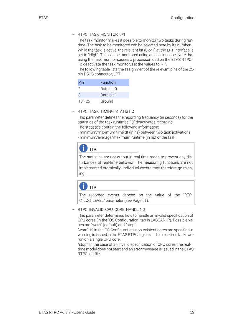
– RTPC_TASK_MONITOR_0/1The task monitor makes it possible to monitor two tasks during run-time. The task to be monitored can be selected here by its number.While the task is active, the relevant bit (0 or1) at the LPT interface is set to "High". This can be monitored using an oscilloscope. Note that using the task monitor causes a processor load on the ETAS RTPC. To deactivate the task monitor, set the values to "-1".The following table lists the assignment of the relevant pins of the 25-pin DSUB connector, LPT.
– RTPC_TASK_TIMING_STATISTICThis parameter defines the recording frequency (in seconds) for the statistics of the task runtimes. "0" deactivates recording.The statistics contain the following information:- minimum/maximum time dt (in ns) between two task activations- minimum/average/maximum runtime (in ns) of the task
– RTPC_INVALID_CPU_CORE_HANDLINGThis parameter determines how to handle an invalid specification of CPU cores (in the "OS Configuration" tab in LABCAR-IP). Possible val-ues are "warn" (default) and "stop"."warn": If, in the OS Configuration, non-existent cores are specified, a warning is issued in the ETAS RTPC log file and all real-time tasks are run on a single CPU core."stop": In the case of an invalid specification of CPU cores, the real-time model does not start and an error message is issued in the ETAS RTPC log file.
Pin Function2 Data bit 03 Data bit 118 - 25 Ground
TIPThe statistics are not output in real-time mode to prevent any dis-turbances of real-time behavior. The measuring functions are notimplemented atomically. Individual events may therefore go miss-ing.
TIPThe recorded events depend on the value of the "RTP-C_LOG_LEVEL" parameter (see Page 51).
ETAS RTPC V6.3.7 - User’s Guide 52

ETAS Configuration
– RTOS_TASK_STACKSIZEETAS RTPC uses a separate stack for each running task. The size of this stack (in kB = 1024 Byte) can be defined using this parameter. A useful value is 1024 kB.
– RTOS_TRACE_BUFFERSIZEETAS RTPC has an automatic internal serial protocol which is useful when, for example, tests are carried out to assess the performance of simulation models.This parameter is used to determine the size of the buffer (in the unit "number of events") before the data is written to a protocol file (*.rtt). This file can be accessed using Main Page → Simulation Controller → Trace File Access and then displayed and analyzed with RTA-TRACE.
– RTPC_COMPILE_OPTIMIZATIONETAS RTPC uses the GNU C Compiler "gcc" – code generation opti-mization can be set in 4 steps (0 ... 3) which correspond to the gcc compiler options -O0 ... -O3. The larger the number, the better the optimization - this does, however, also mean that more time is required for compilation.If you are not sure about this setting, select "1" or "2".
– RTPC_COMPILE_LINK_DEBUGIf you set this parameter to "yes", the compiled object files and the executable file are assigned debug information. This can be useful when detecting errors in the simulation model (see “Debug/Disassemble” on page 56).
• RTPC_COMPILE_SWAPSPACE_MB
When using large Simulink models, the C files generated can be very large. This can lead to the computer not having enough disk space available.This parameter enables you to make additional disk space available for the compilation phase. This space is in the compile.swapfile file and is only used for the compilation of the model, not for the sim-ulation. Possible values are 0, 256, 512, 768 and 1024 - these figures specify the size of the swap file on the hard disk in megabytes.If the value is set to 0, any swap file created previously is deleted. The value is set to 0 by default - if there are no problems during compila-tion, continue to use this setting.
The selected settings are saved using the Save RTPC Configuration button – Discard Changes discards changed settings.
TIPIf models with lots of tasks are used, the stack size may have to bereduced due to the limited size of the RAM.
TIPOnly set this option if it is absolutely necessary as the executablefile becomes very large as a result.
ETAS RTPC V6.3.7 - User’s Guide 53

ETAS Configuration
• Clock Synchronization
Click Synchronize to compare and synchronize real-time PCclock and host clock.
• System Configuration
This part is used to configure the PC hardware. The options are automat-ically set correctly the first time ETAS RTPC is booted. Modification is therefore not necessary. If an Ethernet interface is installed at a later date, the "RTPC_SYS_ETHn" (n = 1 ... 4) option has to be changed from "None" to "present".Save your selection by clicking the System Configuration button.
• System Boot Settings
ETAS RTPC saves two complete software versions on separate parti-tions of the real-time PC. This enables a risk-free return to a familiar soft-ware version. You can select which software version is to be used when the system is next booted in the selection box. This selection is saved using the Set Boot Version button.
• Reboot System
Reboot System restarts ETAS RTPC with the selected software version.
4.2.3.5 Installation/Update• Apply Update
The current ETAS RTPC version can be updated with software updates via the web interface. These software updates can be obtained directly from ETAS.
- Under "Upload Update File" click the Browse... button to select the file with the update (extension *.tgz).
- Select Upload to transfer the file to the real-time PC.
The uploaded file is now selected under "Select Update to Apply".
- If several updates have been uploaded, select the relevant update to be activated.
- Under "Select System to Update" select the software version to be updated. The software version currently active is shown ("Active").
- Click the Apply Update button.
Updates carried out to date are listed under "Applied Updates".
Under "Delete Installed Update Files" you can delete files no longer required.
- Activate the files to be deleted and click Delete.
• Install New Version
The "Install New Version" function is used to execute a complete new installation. ETAS RTPC saves all software versions installed to date from CD on the hard disk of the real-time PC. These versions can be writ-ten back to any partition.There are two ways of making installation files available on the hard disk of the real-time PC:
ETAS RTPC V6.3.7 - User’s Guide 54
ETAS Configuration
– Upload Image file An image (on your local system or on a network resource) is trans-ferred to the real-time PC.
– Check CD/DVD-ROM diskThis is where the optical drive of the user PC is checked for the pres-ence of a ETAS RTPC installation disk. If one is found, the image file is transferred to the real-time PC.
The images provided in this way can now be selected using "Select Soft-ware Image" (see below).
- Select the partition installation should take place in under "Install Partition".
Every partition except the active one can be overwritten.
- Select which version is to be installed under "Select Software Image".
- Use the "Use the existing configuration...." option to specify whether the existing configuration of ETAS RTPC is to be used for this version or whether standard values are to be used.
- If you leave the "Skip implicit updates" option disabled, all avail-able updates for the relevant software version are also auto-matically installed.
- Click Install.
The version to be booted is selected in "Configuration" (see “System Boot Settings” on page 54).Images on the hard disk of the real-time PC which are no longer needed can be marked under "Delete Installed Software Images" and then deleted using Delete.
• Clone Installed Version
You can clone versions of ETAS RTPC that have already been installed by generating an installable file (*.tgz) and downloading this file to your operating PC. For a detailed description of this procedure, refer to the section “Cloning Installed Versions” on page 17.
ETAS RTPC V6.3.7 - User’s Guide 55

ETAS Configuration
4.2.3.6 System InfoThe "System Info" function shows various information on the status of ETAS RTPC. If an error occurs, this page can be saved and used for analysis pur-poses.
• Log File messages
The messages recorded are shown in this window. It is also possible– to have the complete file displayed (View complete log file),– to generate a ZIP archive which contains the log file as well as other
files with system information (Generate ZIP file report) or– to generate an encrypted ZIP archive (password: etas) (Encrypted
ZIP).
• Realtime Process Report
This provides detailed information on running real-time processes.• System Information
System information of the real-time PC is shown here.• Cyclictest - Test Program
This is where the test program "cyclictest" can be launched - the results are also shown on this page. For a detailed description, please refer to “Testing Hardware Performance with "cyclictest"” on page 37.
• CPU Performance Monitor
Uses the "CPU Performance Monitor" registers to analyze CPU perfor-mance.
• LABCAR I/O Hardware Information
This provides detailed information on the connected I/O hardware (VME-bus and PCI/PCIe boards).
• Applied Updates
Contains information on installed updates.• Debug/Disassemble
If the "RTPC_COMPILE_LINK_DEBUG" parameter has been set (see Page 53), the model can be examined here for errors.
TIPAs the ETAS firewall only accepts encrypted ZIP files, you mustselect this option if you want to send a report archive to ETAS by e-mail.
ETAS RTPC V6.3.7 - User’s Guide 56

ETAS Configuration
4.2.3.7 License ManagementThis is where the licenses for ETAS RTPC and the FlexRay boards are man-aged.
• ETAS RTPC Runtime Licenses
– License Information Shows the MAC address to which the license is linked, the names of the active licenses and the license file itself.
– License File Upload This is where you can upload a license file on the host PC to the real-time PC (Upload).
• Elektrobit Device Licenses
This is where the licenses for the FlexRay board from Elektrobit can be managed.The serial numbers of the connected are determined – then you can assign a license file to each board.
ETAS RTPC V6.3.7 - User’s Guide 57

ETAS Configuration
- To transfer a license file from the user PC to a EB_5X00 board, select the board serial number.
- Select the file with Browse and click Write.
- To transfer a license file from a board to the user PC, select the board serial number and click Read.
4.2.3.8 Documentation The "Documentation" link leads you to a directory containing the following documents:
– The manual on ETAS RTPC V6.3.7 – The current release notes– A list of PCs approved by ETAS– Two documents with information on the BIOS settings of the PCs
from ETAS
ETAS RTPC V6.3.7 - User’s Guide 58

ETAS Troubleshooting
5 TroubleshootingThis chapter presents the description of some typical problems with possible solutions.
A When ETAS RTPC is started up, the sequence of error notes is played
– Cause:The Simulation Controller could not be started.
– Remedy:See “Simulation Controller mode cannot be activated” on page 61
B The ETAS RTPC Web interface cannot be accessed
– Cause:Ethernet connection does not exist, is defective or the settings are incorrect.
– Remedy 1:Execute the command ping 192.168.40.14. If you receive an answer from ETAS RTPC, check the settings of your Web browser (e.g. proxy settings).
– Remedy 2:If you do not receive an answer from ETAS RTPC, check the Ethernet cable. Make sure that you are using a crossover cable.
– Remedy 3:If the cable is OK, check the configuration of the Ethernet interface (IP address: 192.168.40.240, net mask: 255.255.255.0)
– Remedy 4:In your Internet configuration, a proxy server is configured for the LAN. To be able to access the ETAS RTPC web interface, the IP address of the real-time PC (192.168.40.14) must be included in the list of exceptions that should not use the proxy server.To do so, proceed as follows:
1. In the Windows Start menu, select Settings → Control Panel → Internet Options.
The "Internet Properties" window opens.
ETAS RTPC V6.3.7 - User’s Guide 59

ETAS Troubleshooting
2. Select the "Connections" tab and click LAN settings.
The "Local Area Network (LAN) Settings" window opens.
3. Click Advanced in the "Proxy server" field.
The "Proxy Settings" window opens.
4. Enter the IP address of the real-time PC in the "Exceptions" field (192.168.40.14).
5. Close one window after the other with OK.
ETAS RTPC V6.3.7 - User’s Guide 60

ETAS Troubleshooting
C Compiling models does not work
– Cause:The real-time PC is not connected to the user PC or is switched off.
– Remedy:Connect the real-time PC or switch it on. Check communication by calling the Web interface (http://192.168.40.14 or http://rtpc).
D The project download ("Open Experiment") in LABCAR-OPERATOR does not work
– Cause 1:Simulation Controller has not been started
– Remedy 1:Use the Web interface to check whether the Simulation Controller has been started. Activate Simulation Controller mode if necessary.
– Cause 2:ES1130 firmware is not compatible with ETAS RTPC.
– Remedy 2:Check whether the firmware which is compatible with ETAS RTPC has been programmed on the ES1130. See the configuration page in the web interface for more details.
E Simulation Controller mode cannot be activated
– Cause 1:The ES1130 has not been connected or is switched off. (HiL mode).
– Remedy 1:Check whether the ES1130 has been connected and is switched on. Call the "ES1130 Detection" function under "Configuration Support". The window below shows the result of the hardware scan. The fol-lowing line should be visible:
Ethernet Controller [eth1]: Connected to Target ES1130
ETAS RTPC V6.3.7 - User’s Guide 61

ETAS Troubleshooting
– Cause 2:The settings for RTPC_USAGE_ETH1 are not correct
– Remedy 2:Check the settings for RTPC_USAGE_ETH1 in the configuration dia-log and correct these (see “Applications” on page 44).
– Cause 3:There is an interrupt conflict in the Ethernet interface.
– Remedy 3:If an interrupt conflict has been registered on the configuration page of the web interface, insert the board into another slot or deactivate unnecessary peripheral devices in the PC BIOS (e.g. USB or sound support).
ETAS RTPC V6.3.7 - User’s Guide 62

ETAS Glossary
6 GlossaryThis chapter explains technical terms used in the manual. The terms are listed in alphabetic order.
APIApplication Programmer's Interface
BIOSBasic Input Output System - the firmware of the PC
CANController Area Network (ISO 15765), a multi-master broadcast serial bus standard for connecting ECUs
CPU Central Processing Unit
DSUBA common hardware connector type
DVDDigital Versatile Disc
DVEDriver-Vehicle-Environment
EVEETAS Virtual ECU
Eth0Designation of the Ethernet port for connecting the host PC
Eth1Designation of the Ethernet port for connecting hardware like ES1130 or ES4440
GBGigabyte
GNUOpen source software community
HiLHardware-in-the-Loop
HTTPHypertext Transfer Protocol
IDIdentification key
IDE Integrated Drive Electronics
IPInternet Protocol
INCAMeasurement, Calibration, and Diagnosis tool available from ETAS
ISOInternational Organization for Standardization
ETAS RTPC V6.3.7 - User’s Guide 63

ETAS Glossary
LANLocal Area Network
LPTParallel port (IEEE-1284)
MBMegabyte
NTPNetwork Time Protocol
PCPersonal computer (desktop or laptop)
PCIePCI Express (Peripheral Component Interconnect Express)
PS/2Serial input for PCs
RAMRandom Access Memory
RTPCReal Time PC
UDPUser Datagram Protocol – a network protocol
URLUniform Resource Locator
VMEA common bus standard
VT-dIntel's Virtualization Technology for Directed I/O
XPA Microsoft Windows release
ZIPCompressed archive file format
ETAS RTPC V6.3.7 - User’s Guide 64

ETAS ETAS Contact Addresses
ETAS RTPC V6.3.7 - User’s Guide 65
7 ETAS Contact Addresses
ETAS HQETAS GmbH
ETAS Subsidiaries and Technical SupportFor details of your local sales office as well as your local technical support team and product hotlines, take a look at the ETAS website:
Borsigstraße 24 Phone: +49 711 3423-070469 Stuttgart Fax: +49 711 3423-2106Germany WWW: www.etas.com
ETAS subsidiaries WWW: www.etas.com/en/contact.php
ETAS technical support WWW: www.etas.com/en/hotlines.php

ETAS Index
Index
AAutomatic configuration . . . . . . . . . . . . .49BBenchmark indicator . . . . . . . . . . . . . . . .37BIOS
Settings . . . . . . . . . . . . . . . . . . . . . . . .11CCAN Board . . . . . . . . . . . . . . . . . . . . . . . . .20CAN Trace . . . . . . . . . . . . . . . . . . . . . . . . .26CAN/CANFD-Abstraction . . . . . . . . . . . . .39Clock Synchronization . . . . . . . . . . . 19, 54Clone
install versions . . . . . . . . . . . . . . . . . .55Configuration . . . . . . . . . . . . . . . . . . . . . . .44CPU Core Load . . . . . . . . . . . . . . . . . . . . .36CPU Performance Monitor . . . . . . . . . . .56cyclictest . . . . . . . . . . . . . . . . . . . . . . . . . . .37DData Protection Declaration . . . . . . . . . . .6Delivery scope . . . . . . . . . . . . . . . . . . . . . . .9EETAS Contact Addresses . . . . . . . . . . . . .65Ethernet Order . . . . . . . . . . . . . . . . . . . . . .51FFlexRay Board . . . . . . . . . . . . . . . . . . . . . .20HHardware requirements . . . . . . . . . . . . . .10Hardware-in-the-Loop (HiL) . . . . . . . . . . .44Hyper-threading . . . . . . . . . . . . . . . . . . . . .11IInstallation . . . . . . . . . . . . . . . . . . . . . . . . .12LLABCAR I/O hardware
information . . . . . . . . . . . . . . . . . . . . .56License Management . . . . . . . . . . . . . . . .57Licensing . . . . . . . . . . . . . . . . . . . . . . . . . . .16LIN-Abstraction . . . . . . . . . . . . . . . . . . . . .39MMassive I/O . . . . . . . . . . . . . . . . . . . . . . . .45Model-in-the-Loop (MiL) . . . . . . . . . . . . . .44OOperating mode
Ethernet Bridge . . . . . . . . . . . . . . . . . .22Idle/Configuration . . . . . . . . . . . . . . .22Power Down . . . . . . . . . . . . . . . . . . . .22Simulation Controller . . . . . . . . . . . . .21
RReal-Time Plugins . . . . . . . . . . . . . . . . . . .32Realtime Process Report . . . . . . . . . . . . .56
RTOS_TASK_STACKSIZE . . . . . . . . . . . .53RTOS_TRACE_BUFFERSIZE . . . . . . . . . .53RTPC_COMPILE_LINK_DEBUG . . . . . . . .53RTPC_COMPILE_OPTIMIZATION . . . . . .53RTPC_COMPILE_SWAPSPACE_MB . . . .53RTPC_INVALID_CPU_CORE_HANDLING .
52RTPC_LOG_LEVEL . . . . . . . . . . . . . . . . . .51RTPC_NAME . . . . . . . . . . . . . . . . . . . . . . .51RTPC_POWER_UP_MODE . . . . . . . . . . . .51RTPC_TASK_MONITOR_0/1 . . . . . . . . . .52RTPC_TASK_TIMING_STATISTIC . . . . .52Runtime Trace . . . . . . . . . . . . . . . . . . . . . .24SSimulation
step-by-step execution . . . . . . . . . . .30Step-by-step execution of the simulation .
30System Boot Settings . . . . . . . . . . . . . . . .54System configuration
HiL test system . . . . . . . . . . . . . . . . .15System requirements . . . . . . . . . . . . . . . . . 9TTroubleshooting . . . . . . . . . . . . . . . . . . . .59VVMEbus reset . . . . . . . . . . . . . . . . . . . . . .22WWeb interface . . . . . . . . . . . . . . . . . . . . . . .46
functions . . . . . . . . . . . . . . . . . . . . . . .48navigation . . . . . . . . . . . . . . . . . . . . . .47
ETAS RTPC V6.3.7 - User’s Guide 66

67
Index ETAS
ETAS RTPC V6.3.7 - User’s Guide