ET 200eco PN - Siemens AG · ET 200eco PN Operating Instructions, 01/2015, A5E01250250-AH 3 Preface...
256
ET 200eco PN ___________ ___________ ___________________ ___________________ ___________________ ___________________ ___________________ ___________________ ___________________ ___________________ ___________________ ___________________ ___________________ ___________________ ___________________ ___________________ ___________________ ___________________ ___________________ ___________________ SIMATIC Distributed I/O ET 200eco PN Operating Instructions 01/2015 A5E01250250-AH Preface Product overview 1 Installing 2 Wiring 3 Configuring 4 Commissioning 5 Maintenance 6 Interrupt, error, and system messages 7 General technical data 8 I/O device digital inputs/digital outputs 9 IO-Link Master 10 I/O device analog input/analog output 11 Terminal block and voltage distributor 12 Signal names A Order numbers B Dimensional drawings C Connection examples D I/O address space E Response times for analog input device and output device F Fail-safe shutdown of ET 200eco PN standard modules G
Transcript of ET 200eco PN - Siemens AG · ET 200eco PN Operating Instructions, 01/2015, A5E01250250-AH 3 Preface...
ET 200eco PN
___________ ___________ ___________________ ___________________ ___________________ ___________________ ___________________ ___________________ ___________________ ___________________ ___________________ ___________________ ___________________ ___________________ ___________________ ___________________ ___________________ ___________________ ___________________ ___________________
SIMATIC
Distributed I/O ET 200eco PN
Operating Instructions
01/2015 A5E01250250-AH
Preface
Product overview 1
Installing 2
Wiring 3
Configuring 4
Commissioning 5
Maintenance 6
Interrupt, error, and system messages
7
General technical data 8
I/O device digital inputs/digital outputs
9
IO-Link Master 10
I/O device analog input/analog output
11 Terminal block and voltage distributor
12
Signal names A
Order numbers B
Dimensional drawings C
Connection examples D
I/O address space E
Response times for analog input device and output device
F Fail-safe shutdown of ET 200eco PN standard modules
G

Siemens AG Division Digital Factory Postfach 48 48 90026 NÜRNBERG GERMANY
A5E01250250-AH 02/2015 Subject to change
Copyright © Siemens AG 2012 - 2015. All rights reserved
Legal information Warning notice system
This manual contains notices you have to observe in order to ensure your personal safety, as well as to prevent damage to property. The notices referring to your personal safety are highlighted in the manual by a safety alert symbol, notices referring only to property damage have no safety alert symbol. These notices shown below are graded according to the degree of danger.
DANGER indicates that death or severe personal injury will result if proper precautions are not taken.
WARNING indicates that death or severe personal injury may result if proper precautions are not taken.
CAUTION indicates that minor personal injury can result if proper precautions are not taken.
NOTICE indicates that property damage can result if proper precautions are not taken.
If more than one degree of danger is present, the warning notice representing the highest degree of danger will be used. A notice warning of injury to persons with a safety alert symbol may also include a warning relating to property damage.
Qualified Personnel The product/system described in this documentation may be operated only by personnel qualified for the specific task in accordance with the relevant documentation, in particular its warning notices and safety instructions. Qualified personnel are those who, based on their training and experience, are capable of identifying risks and avoiding potential hazards when working with these products/systems.
Proper use of Siemens products Note the following:
WARNING Siemens products may only be used for the applications described in the catalog and in the relevant technical documentation. If products and components from other manufacturers are used, these must be recommended or approved by Siemens. Proper transport, storage, installation, assembly, commissioning, operation and maintenance are required to ensure that the products operate safely and without any problems. The permissible ambient conditions must be complied with. The information in the relevant documentation must be observed.
Trademarks All names identified by ® are registered trademarks of Siemens AG. The remaining trademarks in this publication may be trademarks whose use by third parties for their own purposes could violate the rights of the owner.
Disclaimer of Liability We have reviewed the contents of this publication to ensure consistency with the hardware and software described. Since variance cannot be precluded entirely, we cannot guarantee full consistency. However, the information in this publication is reviewed regularly and any necessary corrections are included in subsequent editions.
ET 200eco PN Operating Instructions, 01/2015, A5E01250250-AH 3
Preface
Purpose of the manual The information in this manual enables you to operate the ET 200eco PN distributed I/O device on PROFINET IO as an IO Device.
Basic knowledge required This manual presumes a general knowledge in the field of automation engineering.
The manual describes the components based on the data valid at the time of its release. SIEMENS reserves the right of including a product information for each new component, and for each component of a later version.
Scope of this manual This manual applies to the ET 200eco PN distributed I/O device.
Changes compared to the previous version Compared with the previous version, this manual includes the following changes/additions:
Updating the terminal markings
CE marking The SIMATIC S7 ET 200eco PN distributed I/O device product series fulfills the requirements and safety objectives of the following EC directives.
EC Directive 73/23/EEC "Low-voltage Directive"
EC Directive 2004/108/EC "EMC Directive"
C-Tick-Mark The SIMATIC S7 ET 200eco PN distributed I/O device product series fulfills the requirements of AS/NZS 2064 (Australia and New Zealand).
Standards The SIMATIC S7 ET 200eco PN distributed I/O device product series fulfills the requirements and criteria of IEC 61131-2.
The ET 200eco PN distributed I/O device is based on IEC 61784-1:2002 Ed1 CP 3/1.
Preface
ET 200eco PN 4 Operating Instructions, 01/2015, A5E01250250-AH
Scope of information In addition to this manual, you need:
The manual for the IO Controller you are using
System manual SIMATIC PROFINET system description (http://support.automation.siemens.com/WW/view/en/19292127)
Programming manual Migration from PROFIBUS DP to PROFINET IO (http://support.automation.siemens.com/WW/view/en/19289930)
Guide This manual describes the hardware of the ET 200eco PN distributed I/O device. It consists of instructive sections and reference sections (specifications).
Topics covered in this manual include
Installing and wiring the ET 200eco PN distributed I/O device
Commissioning and diagnostics of the ET 200eco PN distributed I/O device
Components of the ET 200eco PN distributed I/O device
Order numbers
Important terms are explained in the glossary.
The index helps you to quickly find all texts relevant to your keyword.
Recycling and disposal ET 200eco PN can be recycled owing to its low pollutant content.
For ecologically compatible recycling and disposal of your old device, contact a certificated disposal service for electronic scrap.
Additional support If you have any further questions about the use of products described in this manual, and do not find the right answers there, contact your local Siemens representative:
You can find your representative on the Internet (http://www.automation.siemens.com/partner/guiwelcome.asp?lang=en).
A guide to the technical documentation for the various SIMATIC products and systems is available on the Internet (http://www.siemens.com/automation/support-request).
The online catalog and ordering systems are available on the Internet (http://mall.automation.siemens.com).
Preface
ET 200eco PN Operating Instructions, 01/2015, A5E01250250-AH 5
Training center Siemens offers corresponding courses to get you started with your ET 200eco PN distributed I/O device and the SIMATIC S7 automation system. Please contact your regional training center or our main training center in D-90327 Nuremberg, Germany, for details.
Additional information can be found on the Internet (http://www.sitrain.com/index_en.html).
Technical Support You can contact Technical Support for all A&D products by means of the Support Request Web form on the Internet (http://www.siemens.com/automation/support-request).
Additional information about Siemens Technical Support is available on the Internet (http://www.siemens.com/automation/service).
Service & Support on the Internet In addition to our documentation, we offer a comprehensive knowledge base on the Internet (http://www.siemens.de/automation/csi_en_WW).
There, you will find the following information:
Our newsletter, providing the latest information on your products
The right documents for your product on our Service & Support pages
Worldwide forum in which users and experts exchange ideas
Your local Automation & Drives partner in our partner database.
Information about on-site services, repairs, spare parts, and lots more.
Security information Siemens provides products and solutions with industrial security functions that support the secure operation of plants, solutions, machines, equipment and/or networks. They are important components in a holistic industrial security concept. With this in mind, Siemens’ products and solutions undergo continuous development. Siemens recommends strongly that you regularly check for product updates.
For the secure operation of Siemens products and solutions, it is necessary to take suitable preventive action (e.g. cell protection concept) and integrate each component into a holistic, state-of-the-art industrial security concept. Third-party products that may be in use should also be considered. You can find more information about industrial security on the Internet (http://www.siemens.com/industrialsecurity).
To stay informed about product updates as they occur, sign up for a product-specific newsletter. You can find more information on the Internet (http://support.automation.siemens.com).

ET 200eco PN 6 Operating Instructions, 01/2015, A5E01250250-AH
Table of contents
Preface ................................................................................................................................................... 3
1 Product overview .................................................................................................................................. 10
1.1 Distributed I/O device – Overview .......................................................................................... 10
1.2 ET 200eco PN Distributed I/O Device ................................................................................... 12
2 Installing ............................................................................................................................................... 19
2.1 Installation without mounting rail ............................................................................................ 19
2.2 Installation with mounting rail ................................................................................................. 23
2.3 Mounting position, mounting dimensions ............................................................................... 23
2.4 Installing the terminal block .................................................................................................... 24
2.5 Replacing labels ..................................................................................................................... 26
2.6 Removing ET 200eco PN ...................................................................................................... 27
3 Wiring ................................................................................................................................................... 28
3.1 General rules and regulations for operating an ET 200eco PN ............................................. 28
3.2 Operating ET 200eco PN on grounded mains ....................................................................... 29
3.3 Electrical configuration of ET 200eco PN .............................................................................. 32
3.4 Technical specifications of the lines....................................................................................... 33
3.5 Wiring the ET 200eco PN ...................................................................................................... 34 3.5.1 Wiring the ET 200eco PN to functional earth (FE)................................................................. 34 3.5.2 Wiring I/O devices .................................................................................................................. 36
3.6 Pin assignment of connectors ................................................................................................ 39 3.6.1 Pin assignment of the PROFINET connector ........................................................................ 39 3.6.2 Pin assignment for feeding and looping the voltage .............................................................. 40 3.6.3 Pin assignment of digital inputs ............................................................................................. 42 3.6.4 Pin assignment of digital outputs ........................................................................................... 44 3.6.5 Pin assignment for parameterizable digital input/digital output ............................................. 48 3.6.6 Pin assignment for IO-Link Master......................................................................................... 49 3.6.7 Pin assignment for analog inputs ........................................................................................... 51 3.6.8 Pin assignment M12 compensation connector for thermocouples ........................................ 56 3.6.9 Pin assignment for analog output .......................................................................................... 57
3.7 Wiring the terminal block ........................................................................................................ 58
3.8 Wiring the voltage distributor ................................................................................................. 62
3.9 Looping PROFINET and the supply voltage .......................................................................... 64
Table of contents
ET 200eco PN Operating Instructions, 01/2015, A5E01250250-AH 7
4 Configuring ........................................................................................................................................... 65
4.1 Configuring ET 200eco PN ..................................................................................................... 65
4.2 Configuring the IO-Link Master ............................................................................................... 66
4.3 Device names for ET 200eco PN ........................................................................................... 68
4.4 Ports of ET 200eco PN ........................................................................................................... 69
4.5 Isochronous real-time communication .................................................................................... 70
4.6 Prioritized startup .................................................................................................................... 71
4.7 Device replacement without programming device .................................................................. 71
4.8 Media redundancy .................................................................................................................. 72
4.9 Reset to factory settings ......................................................................................................... 72
4.10 SNMP ...................................................................................................................................... 73
5 Commissioning ..................................................................................................................................... 74
5.1 Commissioning ET 200eco PN ............................................................................................... 74
6 Maintenance ......................................................................................................................................... 76
6.1 Replacing the fuse .................................................................................................................. 76
6.2 Online firmware update by means of STEP 7 Manager ......................................................... 77
6.3 Acyclic data exchange with the FB IOL_CALL ....................................................................... 79
6.4 Exchange object ..................................................................................................................... 79
7 Interrupt, error, and system messages .................................................................................................. 80
7.1 Interrupts of ET 200eco PN .................................................................................................... 80
7.2 Maintenance interrupts ........................................................................................................... 81
7.3 Diagnostics by means of LED display .................................................................................... 82 7.3.1 Diagnostics using the LED display on the I/O devices ........................................................... 82 7.3.2 Diagnostics using the LED display on the IO-Link Master...................................................... 84 7.3.3 Diagnostics using the LED display at the voltage distributor .................................................. 86
7.4 Diagnostics messages of the I/O devices ............................................................................... 87
7.5 Diagnostics with STEP 7......................................................................................................... 87 7.5.1 Reading diagnostics data ....................................................................................................... 87 7.5.2 Channel diagnostics................................................................................................................ 88 7.5.3 Error classes for I/O devices ................................................................................................... 89 7.5.4 STOP of the IO Controller and recovery of the IO Device ...................................................... 91
8 General technical data .......................................................................................................................... 92
8.1 Standards and certifications ................................................................................................... 92
8.2 EMC compatibility, shipping and storage conditions .............................................................. 94
8.3 Mechanical and climatic environmental conditions ................................................................. 96
8.4 Specification of dielectric tests, protection class, degree of protection, and rated voltage of ET 200eco PN ...................................................................................................... 100
Table of contents
ET 200eco PN 8 Operating Instructions, 01/2015, A5E01250250-AH
9 I/O device digital inputs/digital outputs .................................................................................................. 101
9.1 I/O device digital inputs ........................................................................................................ 101 9.1.1 I/O device 8 DI DC 24 V 4xM12 ........................................................................................... 101 9.1.2 I/O device 8 DI DC 24 V 8xM12 ........................................................................................... 105 9.1.3 I/O device 16 DI DC 24 V 8xM12 ......................................................................................... 109 9.1.4 Parameter overview digital inputs ........................................................................................ 114
9.2 I/O device digital outputs ...................................................................................................... 115 9.2.1 I/O device 8 DO DC 24 V/1.3A 4xM12................................................................................. 115 9.2.2 I/O device 8 DO DC 24 V/0.5A 4xM12................................................................................. 120 9.2.3 I/O device 8 DO DC 24 V/1.3A 8xM12................................................................................. 125 9.2.4 I/O device 8 DO DC 24V/2.0A 8xM12.................................................................................. 130 9.2.5 I/O device 16 DO DC 24 V/1.3A 8xM12 .............................................................................. 135 9.2.6 Parameter overview digital outputs ...................................................................................... 140
9.3 I/O device digital inputs/digital outputs ................................................................................ 142 9.3.1 I/O device 8 DIO DC 24V/1.3A 8xM12................................................................................. 142 9.3.2 Parameter overview digital inputs/digital outputs ................................................................. 147
10 IO-Link Master ..................................................................................................................................... 148
10.1 IO-Link Master ...................................................................................................................... 148
10.2 Parameters for IO-Link Master ............................................................................................. 155
10.3 Functions .............................................................................................................................. 157
11 I/O device analog input/analog output .................................................................................................. 159
11.1 I/O device analog input ........................................................................................................ 159 11.1.1 I/O device 8 AI 4 U/I + 4 RTD/TC 8xM12 ............................................................................. 159 11.1.2 8 AI RTD/TC 8×M12 I/O device ........................................................................................... 168 11.1.3 Parameter overview analog input ........................................................................................ 175 11.1.4 Parameter description analog input ..................................................................................... 181 11.1.5 Analog value representation for measuring ranges with SIMATIC S7 ................................ 187 11.1.6 Measuring ranges of the analog input device in S7 format ................................................. 188 11.1.7 Dynamic reference temperature with module 8 AI RTD/TC 8xM12 .................................... 196
11.2 I/O device analog output ...................................................................................................... 200 11.2.1 I/O device 4 AO U/I 4xM12 .................................................................................................. 200 11.2.2 Parameter overview analog output ...................................................................................... 206 11.2.3 Parameter description analog output ................................................................................... 207 11.2.4 Output ranges of analog output device ................................................................................ 209
11.3 Influence of the range of values ........................................................................................... 210
12 Terminal block and voltage distributor .................................................................................................. 212
12.1 Terminal block ...................................................................................................................... 212
12.2 Voltage distributor ................................................................................................................ 214
A Signal names ....................................................................................................................................... 217
A.1 Signal names ....................................................................................................................... 217
B Order numbers ..................................................................................................................................... 218
B.1 Order numbers ..................................................................................................................... 218
Table of contents
ET 200eco PN Operating Instructions, 01/2015, A5E01250250-AH 9
C Dimensional drawings ......................................................................................................................... 224
C.1 Dimensional drawings ........................................................................................................... 224
D Connection examples .......................................................................................................................... 230
D.1 Connection of resistance thermometers to the analog inputs .............................................. 230
D.2 Connection of thermocouples to the analog inputs .............................................................. 231
E I/O address space ............................................................................................................................... 234
E.1 I/O address space ................................................................................................................. 234
F Response times for analog input device and output device .................................................................. 241
F.1 Response times for analog input device ............................................................................... 241
F.2 Response times for analog output device ............................................................................ 242
G Fail-safe shutdown of ET 200eco PN standard modules ...................................................................... 244
G.1 Back-up oriented shutdown of ET 200eco PN standard modules ........................................ 244
Glossary ............................................................................................................................................. 247
Index................................................................................................................................................... 253
ET 200eco PN 10 Operating Instructions, 01/2015, A5E01250250-AH
Product overview 1 1.1 Distributed I/O device – Overview
Distributed I/O systems – application area A plant configuration quite often features a process I/O configuration in a central automation system.
The wiring of process I/O components installed at a grated distance away from an automation system may soon may soon become highly complex and susceptible for electromagnetic interference.
Distributed I/O systems are are the perfect solution for such configurations.
The controller CPU is located in a central rack.
The I/O systems (inputs and outputs) are operated locally in a distributed configuration.
What is PROFINET IO? PROFINET IO is an open transmission system with real-time functionality defined in accordance with the PROFINET standard. This standard defines a manufacturer-independent communication, automation and engineering model.
Industrial-strength connections are available for wiring the PROFINET components.
PROFINET discards the hierarchical PROFIBUS master/slave concept. and deploys a provider/consumer principle instead. The IO Devices that will be subscribed to by an IO Controller are defined within the planning phase.
The quantity structures are extended in accordance with the available quantities for PROFINET IO. Parameter limits are not exceeded during configuration.
The transmission rate is 100 Mbps.
The configuration interface for users is generally the same as that for PROFIBUS DP (the system is configured in STEP 7 > HW Config).
Product overview 1.1 Distributed I/O device – Overview
ET 200eco PN Operating Instructions, 01/2015, A5E01250250-AH 11
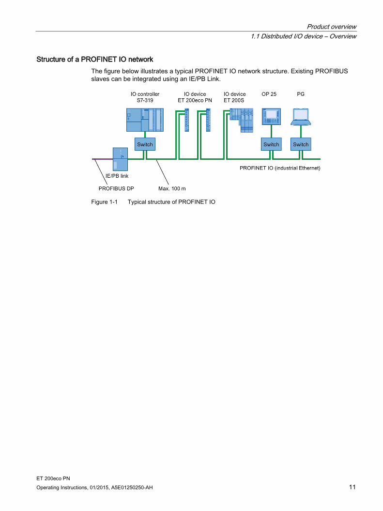
Structure of a PROFINET IO network The figure below illustrates a typical PROFINET IO network structure. Existing PROFIBUS slaves can be integrated using an IE/PB Link.
Figure 1-1 Typical structure of PROFINET IO
Product overview 1.2 ET 200eco PN Distributed I/O Device
ET 200eco PN 12 Operating Instructions, 01/2015, A5E01250250-AH
1.2 ET 200eco PN Distributed I/O Device
Definition The ET 200eco PN distributed I/O device is a compact PROFINET IO device in degree of protection IP65/66 or IP67 and UL Enclosure Type 4x, indoor use only.
Field of application The fields of application of the ET 200eco PN are derived from its special properties.
A robust design and degree of protection IP65/66 or IP67 make the ET 200eco PN distributed I/O device suitable in particular for use in rugged industrial environments.
The compact design of the ET 200eco PN is particularly favorable for applications in confined areas.
The easy handling of ET 200eco PN facilitates efficient commissioning and maintenance.
Properties The ET 200eco PN has the following properties:
Integrated switch with 2 ports
Supported Ethernet services:
– ping
– arp
– Network diagnostics (SNMP)
– LLDP
Interrupts
– Diagnostics interrupts
– Maintenance interrupts
Port diagnostics
Isochronous real-time communication
Prioritized startup
Device replacement without programming device
Media redundancy

Product overview 1.2 ET 200eco PN Distributed I/O Device
ET 200eco PN Operating Instructions, 01/2015, A5E01250250-AH 13
Components of ET 200eco PN The tables below provide an overview of the most important components of ET 200eco PN:
Table 1- 1 Components of ET 200eco PN (30 mm)
Component Function Figure I/O device You connect the sensors and actuators
to the I/O device. The I/O device is available in the following variants: • 8 DI DC 24V 4×M12 • 8 DO DC 24V/1,3A 4×M12 • 8 DO DC 24V/0,5A 4×M12
① SF/MT LED ⑧ X03: Voltage infeed
② BF LED ⑨ X02: Loop-through of the voltage
③ ON LED ⑩ Input/output signal
④ DC 24V LED (for digital output device only) ⑪ MAC address
⑤ P1 LK LED ⑫ X01 P2 LAN: PROFINET IO connection
⑥ P2 LK LED ⑬ X01 P1 LAN: PROFINET IO connection
⑦ Channel status/channel fault

Product overview 1.2 ET 200eco PN Distributed I/O Device
ET 200eco PN 14 Operating Instructions, 01/2015, A5E01250250-AH
Table 1- 2 Components of ET 200eco PN (60 mm)
Component Function Figure I/O device You connect the sensors and actuators
to the I/O device. The I/O device is available in the following variants: • 8 DI DC 24V 8×M12 • 16 DI DC 24V 8×M12 • 8 DO DC 24V/1,3A 8×M12 • 8 DO DC 24V/2,0A 8×M12 • 16 DO DC 24V/1,3A 8×M12 • 8 AI 4 U/I + 4 RTD/TC 8×M12 • 8 AI RTD/TC 8×M12 • 8 DIO DC 24V/1,3A 8×M12
① SF/MT LED ⑧ X03: Voltage infeed
② BF LED ⑨ X02: Loop-through of the voltage
③ ON LED ⑩ Input/output signal
④ DC 24V LED (for digital output device only) ⑪ MAC address
⑤ P1 LK LED ⑫ X01 P2 LAN: PROFINET IO connection
⑥ P2 LK LED ⑬ X01 P1 LAN: PROFINET IO connection
⑦ Channel status/channel fault

Product overview 1.2 ET 200eco PN Distributed I/O Device
ET 200eco PN Operating Instructions, 01/2015, A5E01250250-AH 15
Table 1- 3 Components of ET 200eco PN (60 mm)
Component Function Figure I/O device You connect the sensors and actuators
to the I/O device. The I/O device is available in the following variants: • 4 AO U/I 4×M12
① SF/MT LED ⑧ X03: Voltage infeed
② BF LED ⑨ X02: Loop-through of the voltage
③ ON LED ⑩ Input/output signal
④ DC 24V LED (for digital output device only) ⑪ MAC address
⑤ P1 LK LED ⑫ X01 P2 LAN: PROFINET IO connection
⑥ P2 LK LED ⑬ X01 P1 LAN: PROFINET IO connection
⑦ Channel status/channel fault
Product overview 1.2 ET 200eco PN Distributed I/O Device
ET 200eco PN 16 Operating Instructions, 01/2015, A5E01250250-AH
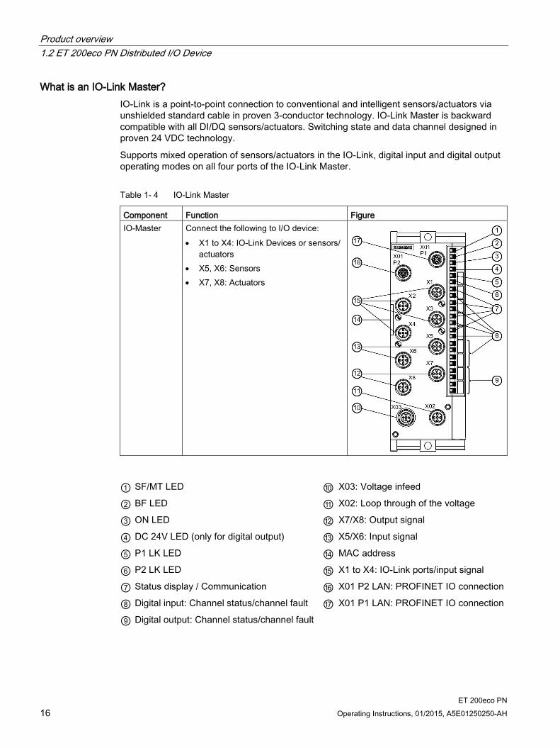
What is an IO-Link Master? IO-Link is a point-to-point connection to conventional and intelligent sensors/actuators via unshielded standard cable in proven 3-conductor technology. IO-Link Master is backward compatible with all DI/DQ sensors/actuators. Switching state and data channel designed in proven 24 VDC technology.
Supports mixed operation of sensors/actuators in the IO-Link, digital input and digital output operating modes on all four ports of the IO-Link Master.
Table 1- 4 IO-Link Master
Component Function Figure IO-Master Connect the following to I/O device:
• X1 to X4: IO-Link Devices or sensors/ actuators
• X5, X6: Sensors • X7, X8: Actuators
① SF/MT LED ⑩ X03: Voltage infeed
② BF LED ⑪ X02: Loop through of the voltage
③ ON LED ⑫ X7/X8: Output signal
④ DC 24V LED (only for digital output) ⑬ X5/X6: Input signal
⑤ P1 LK LED ⑭ MAC address
⑥ P2 LK LED ⑮ X1 to X4: IO-Link ports/input signal
⑦ Status display / Communication ⑯ X01 P2 LAN: PROFINET IO connection
⑧ Digital input: Channel status/channel fault ⑰ X01 P1 LAN: PROFINET IO connection
⑨ Digital output: Channel status/channel fault
Product overview 1.2 ET 200eco PN Distributed I/O Device
ET 200eco PN Operating Instructions, 01/2015, A5E01250250-AH 17
Further components of ET 200eco PN
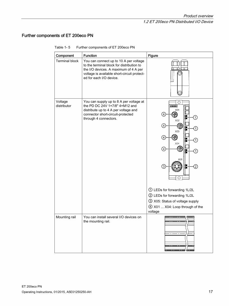
Table 1- 5 Further components of ET 200eco PN
Component Function Figure Terminal block You can connect up to 10 A per voltage
to the terminal block for distribution to the I/O devices. A maximum of 4 A per voltage is available short-circuit protect-ed for each I/O device.
Voltage distributor
You can supply up to 8 A per voltage at the PD DC 24V 1×7/8" 4×M12 and distribute up to 4 A per voltage and connector short-circuit-protected through 4 connectors.
① LEDs for forwarding 1L/2L ② LEDs for forwarding 1L/2L ③ X05: Status of voltage supply ④ X01 ... X04: Loop through of the voltage
Mounting rail You can install several I/O devices on the mounting rail.

Product overview 1.2 ET 200eco PN Distributed I/O Device
ET 200eco PN 18 Operating Instructions, 01/2015, A5E01250250-AH
IO Controller The ET 200eco PN can communicate with all IO controllers that conform to IEC 61158.
To configure an ET 200eco PN, you need STEP 7 V5.4, SP4.
The ET 200eco PN can be configured starting from a CPU with extended diagnostics, see FAQ (https://support.automation.siemens.com/WW/view/en/23678970).
As of which versions of the ET 200eco PN are the individual PROFINET properties available, see FAQ (https://support.automation.siemens.com/WW/view/en/44383954).
ET 200eco PN Operating Instructions, 01/2015, A5E01250250-AH 19
Installing 2
Two installation variants There are two installation variants:
With mounting rail
Without mounting rail
For corresponding conditions, refer to the next chapters.
2.1 Installation without mounting rail
Simple installation The ET 200eco PN distributed I/O device is designed for easy installation.
The I/O device must be mounted on a solid base
and can be prewired.
Requirements Screw type Explanation Cylinder head screw M5 to ISO 1207/ISO 1580 (DIN 84/DIN85)
Minimum screw length: 30 mm. Any washers you might need should conform to DIN 125. Hexagon socket head cap screws M5 to
DIN EN ISO 4762
Tools required Medium-sized screwdriver or 4 mm hex socket driver.

Installing 2.1 Installation without mounting rail
ET 200eco PN 20 Operating Instructions, 01/2015, A5E01250250-AH
Procedure 1. Screw the I/O device onto a level surface.
Screw the I/O device onto the panel at both mounting fixtures on the top and bottom of the front or side (torque: 3 N/m).
Figure 2-1 Mounting the I/O device on a panel (30 mm)

Installing 2.1 Installation without mounting rail
ET 200eco PN Operating Instructions, 01/2015, A5E01250250-AH 21
Figure 2-2 Mounting the I/O device on a panel (60 mm), for example
16 DO DC 24V/1,3A 8×M12
Installing 2.1 Installation without mounting rail
ET 200eco PN 22 Operating Instructions, 01/2015, A5E01250250-AH
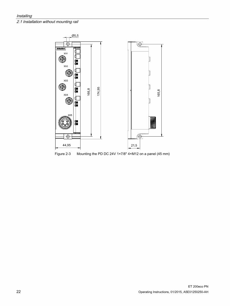
Figure 2-3 Mounting the PD DC 24V 1×7/8" 4×M12 on a panel (45 mm)

Installing 2.2 Installation with mounting rail
ET 200eco PN Operating Instructions, 01/2015, A5E01250250-AH 23
2.2 Installation with mounting rail
Version The mounting rail is available with a length of 500 mm.
Installing the mounting rail Cut the 500-mm rail to suit your requirements and drill mounting holes for the M8 screws. You should distribute the mounting holes evenly at a pitch of 182 mm on the rail, starting at a distance of 12 mm from the edge.
Use the rack screw to bolt the I/O devices onto the mounting rail.
Figure 2-4 Installing the mounting rail
2.3 Mounting position, mounting dimensions
Mounting position The ET 200eco PN can be mounted in any position.
Mounting and clearance dimensions
Table 2- 1 Mounting dimensions
Dimensions single width double width
Mounting width 30 mm 60 mm Mounting height 200 mm 175 mm Mounting depth 49 mm 49 mm

Installing 2.4 Installing the terminal block
ET 200eco PN 24 Operating Instructions, 01/2015, A5E01250250-AH
2.4 Installing the terminal block
Properties The terminal block connects the ET 200eco PN and supplies the I/O device with power.
The terminal block
can be installed separately,
or be screwed on to each I/O device.
Requirements Note that you must wire the terminal block before you install it.
Tools required Recessed head screwdriver, medium size
Installing the terminal block separately You install the terminal block separately.
Remove the screws and then screw them in again at the bottom of the housing.
Figure 2-5 Installing the terminal block separately
Installing 2.4 Installing the terminal block
ET 200eco PN Operating Instructions, 01/2015, A5E01250250-AH 25
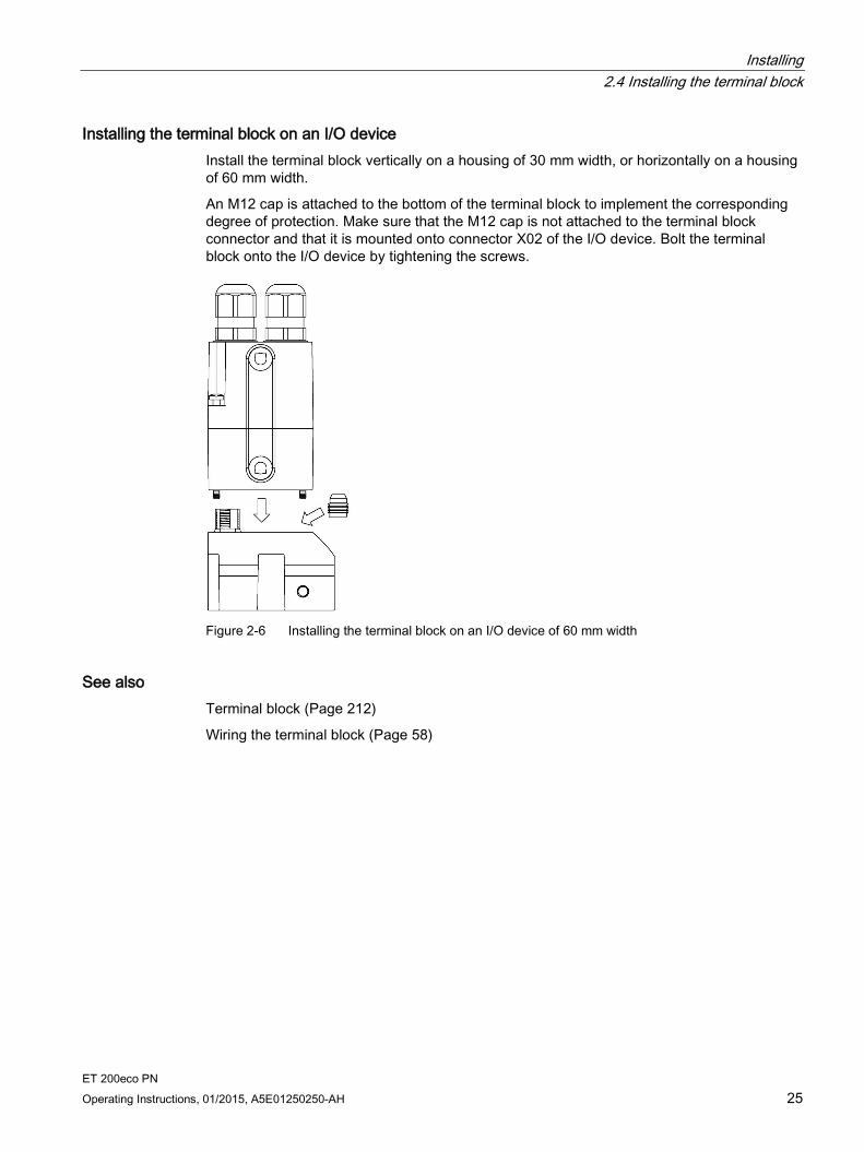
Installing the terminal block on an I/O device Install the terminal block vertically on a housing of 30 mm width, or horizontally on a housing of 60 mm width.
An M12 cap is attached to the bottom of the terminal block to implement the corresponding degree of protection. Make sure that the M12 cap is not attached to the terminal block connector and that it is mounted onto connector X02 of the I/O device. Bolt the terminal block onto the I/O device by tightening the screws.
Figure 2-6 Installing the terminal block on an I/O device of 60 mm width
See also Terminal block (Page 212)
Wiring the terminal block (Page 58)
Installing 2.5 Replacing labels
ET 200eco PN 26 Operating Instructions, 01/2015, A5E01250250-AH
2.5 Replacing labels
Properties You can identify the I/O device and the I/O connectors using the labels. The module is supplied with the labels already clipped into the holder.
1 for the I/O device
4 or 8 for the I/O connectors
Requirements You can order replacement labels.
Tools required 2.5 to 4 mm slotted screwdriver
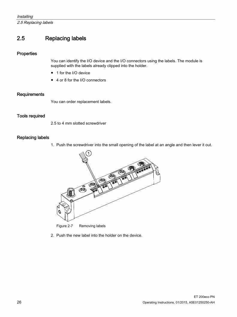
Replacing labels 1. Push the screwdriver into the small opening of the label at an angle and then lever it out.
Figure 2-7 Removing labels
2. Push the new label into the holder on the device.
Installing 2.6 Removing ET 200eco PN
ET 200eco PN Operating Instructions, 01/2015, A5E01250250-AH 27
2.6 Removing ET 200eco PN
Procedure The ET 200eco PN is wired up and operating.
1. Switch off the supply voltage to the ET 200eco PN.
2. Disconnect the wiring from the I/O device.
3. Remove the fixing screws from the I/O device.
Note
Observe the information in chapter Looping PROFINET and the supply voltage (Page 64) when replacing the I/O device.

ET 200eco PN 28 Operating Instructions, 01/2015, A5E01250250-AH
Wiring 3 3.1 General rules and regulations for operating an ET 200eco PN
Introduction When operating the ET 200eco PN distributed I/O device as part of a plant or system, special rules and regulations have to be followed depending on the field of application.
This section provides an overview of the most important rules you have to observe when integrating the ET 200eco PN distributed I/O device in a plant or system.
EMERGENCY-STOP equipment EMERGENCY STOP equipment according to IEC 204 (corresponds to DIN VDE 113) must remain effective in all operating modes of the plant or system.
System startup after specific events The table below identifies situations you must pay attention to when the system starts up after the occurrence of certain events. If ... then ... Startup follows a power dip / failure Startup of the ET 200eco PN after bus communication has been interrupted
Dangerous operating states must be avoided at all times. If necessary, force an "EMERGENCY OFF"!
Startup after releasing the EMERGENCY OFF equipment
Any uncontrolled or undefined startup must be avoided.
24 V DC supply The table shows what you have to observe for the 24 V DC supply. At ... Requirements ... Buildings external lightning protection take lightning protection measures
(for example, lightning protection elements)
24 VDC supply lines, signal lines internal lightning protection
24 V DC supply safe (electrical) isolation of the extra-low voltage Loop-through of supply voltage Voltage drop in the case of loop-through (see Chapter Looping
PROFINET and the supply voltage (Page 64))
Wiring 3.2 Operating ET 200eco PN on grounded mains
ET 200eco PN Operating Instructions, 01/2015, A5E01250250-AH 29
Protection against external electrical interference The table below shows what to observe in order to protect the system against electrical interference or faults. At ... ensure that ... all plants or systems in which the ET 200eco PN is installed
the plant or system is EMC-compatible and properly grounded for the discharge of electromagnetic interference.
supply, signal, and bus lines the wiring arrangement and installation is correct. signal and bus lines a wire break or conductor break does not result in undefined
states of the plant or system.
3.2 Operating ET 200eco PN on grounded mains
Introduction This section provides information about the overall configuration of an ET 200eco PN distributed I/O device with a grounded infeed (TN-S system). The focus in this is set in particular on: disconnecting devices and short-circuit and overload protection according to DIN VDE 0100 and DIN EN 60204-1.
Supply voltages of the ET 200eco PN There are two supply voltages:
1L+ Non-switched supply voltage (electronic/sensor/load supply)
2L+: Switched supply voltage (load voltage supply)
Definition: Grounded infeed The neutral conductor of a TN-S system is always bonded to ground. A simple short-circuit to ground of a live conductor, or of a grounded component of the plant will trip the disconnecting devices.
Safe electrical isolation (SELV/PELV according to IEC 60364-4-41) The ET 200eco PN may only be operated using power supplies/power supply units with safe electrical isolation.
Wiring 3.2 Operating ET 200eco PN on grounded mains
ET 200eco PN 30 Operating Instructions, 01/2015, A5E01250250-AH
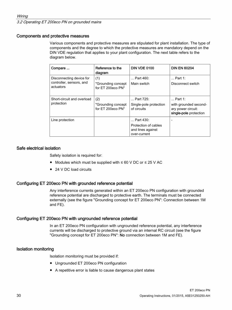
Components and protective measures Various components and protective measures are stipulated for plant installation. The type of components and the degree to which the protective measures are mandatory depend on the DIN VDE regulation that applies to your plant configuration. The next table refers to the diagram below. Compare ... Reference to the
diagram DIN VDE 0100 DIN EN 60204
Disconnecting device for controller, sensors, and actuators
(1) "Grounding concept for ET 200eco PN"
... Part 460: Main switch
... Part 1: Disconnect switch
Short-circuit and overload protection
(2) "Grounding concept for ET 200eco PN"
... Part 725: Single-pole protection of circuits
... Part 1: with grounded second-ary power circuit: single-pole protection
Line protection ... Part 430: Protection of cables and lines against over-current
-
Safe electrical isolation Safety isolation is required for:
Modules which must be supplied with ≤ 60 V DC or ≤ 25 V AC
24 V DC load circuits
Configuring ET 200eco PN with grounded reference potential Any interference currents generated within an ET 200eco PN configuration with grounded reference potential are discharged to protective earth. The terminals must be connected externally (see the figure "Grounding concept for ET 200eco PN": Connection between 1M and FE).
Configuring ET 200eco PN with ungrounded reference potential In an ET 200eco PN configuration with ungrounded reference potential, any interference currents will be discharged to protective ground via an internal RC circuit (see the figure "Grounding concept for ET 200eco PN": No connection between 1M and FE).
Isolation monitoring Isolation monitoring must be provided if:
Ungrounded ET 200eco PN configuration
A repetitive error is liable to cause dangerous plant states

Wiring 3.2 Operating ET 200eco PN on grounded mains
ET 200eco PN Operating Instructions, 01/2015, A5E01250250-AH 31
ET 200eco PN in its overall configuration The figure below shows the overall configuration of the ET 200eco PN distributed I/O device (load voltage supply and grounding concept) with infeed from a TN-S system.
① Disconnecting device for controller, sensors, and actuators ② Short-circuit and overload protection ③ Fuses for line protection ④ Microprocessor and switch ⑤ Main ground line ⑥ When the ET 200eco PN is configured with ungrounded reference potential, the connection
between 1M and FE and 2M and FE is eliminated.
Wiring 3.3 Electrical configuration of ET 200eco PN
ET 200eco PN 32 Operating Instructions, 01/2015, A5E01250250-AH
3.3 Electrical configuration of ET 200eco PN
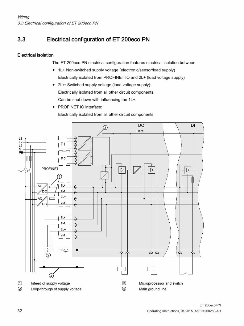
Electrical isolation The ET 200eco PN electrical configuration features electrical isolation between:
1L+ Non-switched supply voltage (electronic/sensor/load supply)
Electrically isolated from PROFINET IO and 2L+ (load voltage supply)
2L+: Switched supply voltage (load voltage supply):
Electrically isolated from all other circuit components.
Can be shut down with influencing the 1L+.
PROFINET IO interface:
Electrically isolated from all other circuit components.
① Infeed of supply voltage ③ Microprocessor and switch ② Loop-through of supply voltage ④ Main ground line

Wiring 3.4 Technical specifications of the lines
ET 200eco PN Operating Instructions, 01/2015, A5E01250250-AH 33
Connection of a digital output to a digital input
WARNING
When a digital output is connected to a digital output, the respective potential groups have to be observed. Depending on the configuration, 1M and 2M may then be connected, resulting in elimination of the galvanic isolation between 1L+ and 2L+.
Line protection Line protection is required in accordance with DIN VDE 0100, i.e., you must always provide external fusing.
The power supplies of the I/O device must be fused using a 24 V DC/4 A miniature circuit breaker with tripping characteristic type B or C.
The power supplies of the terminal block must be fused using a 24 V DC/10 A miniature circuit breaker with tripping characteristic type B or C.
The power supplies of the voltage distributor must be fused using a 24 VDC / 8 A miniature circuit breaker with tripping characteristic type B or C.
3.4 Technical specifications of the lines
Influence of cable length on the supply voltage If you are wiring your configuration, then you must take into account the impact of cable
length on the supply voltage to the ET 200eco PN.
Example
A 10-m cable with Ø 0.75 mm2 has a resistance of 0.5 Ω, which corresponds with a voltage drop of 2 V at a load of 4 A.
CAUTION
If you do not adhere to the maximum infeed currents and the cable cross-sections required for these currents, you will risk overheating the cable insulation and contacts, and damage to the device.

Wiring 3.5 Wiring the ET 200eco PN
ET 200eco PN 34 Operating Instructions, 01/2015, A5E01250250-AH
3.5 Wiring the ET 200eco PN
3.5.1 Wiring the ET 200eco PN to functional earth (FE)
Properties You must connect the ET 200eco PN with the functional earth. The I/O module is
equipped accordingly with a ground terminal.
This connection to functional earth is also required to discharge any interference currents to ground, and for EMC strength.
Requirements Always provide a low-impedance connection to functional earth.
Tools required Stripping tool
Crimp tool
Screwdriver
Required accessories M5 x 8 fixing screw and washers
Grounding cable (copper braid) with a minimum cross-section of 4 mm2
Cable lugs
Wiring 3.5 Wiring the ET 200eco PN
ET 200eco PN Operating Instructions, 01/2015, A5E01250250-AH 35
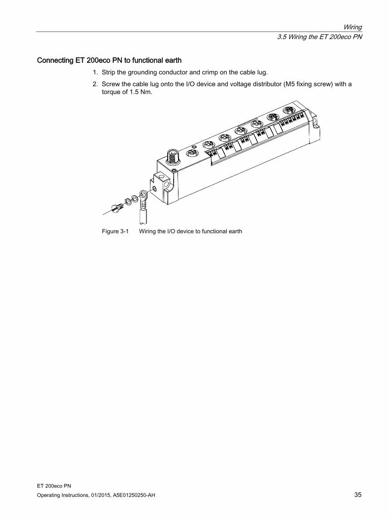
Connecting ET 200eco PN to functional earth 1. Strip the grounding conductor and crimp on the cable lug.
2. Screw the cable lug onto the I/O device and voltage distributor (M5 fixing screw) with a torque of 1.5 Nm.
Figure 3-1 Wiring the I/O device to functional earth

Wiring 3.5 Wiring the ET 200eco PN
ET 200eco PN 36 Operating Instructions, 01/2015, A5E01250250-AH
3.5.2 Wiring I/O devices
Properties Connect the sensors and actuators to the 5-pin M12 circular sockets (X1 to X4, or X1 to X8) on the front panel of the I/O device.
Requirements Shut off the supply voltage before you wire the I/O devices.
Tools required Stripping tool and screwdriver for wiring the M12 cable connector, if you do not use prefabricated cables.
Required accessories Prefabricated cable with 5-pin M12 cable connector
or flexible 3-, 4-, or 5-wire copper cable (conductor cross-section must be ≤ 0.75 mm2) with 5-pin M12 cable connector (see the tables below).
or a Y cable
M12 sealing caps
For order numbers, refer to the appendix Order numbers (Page 218).
Connecting the M12 connector 1. Plug the connector into the relevant circular socket connector on the I/O block. Make sure
the connectors and sockets are properly interlocked (matched joint).
2. Secure the connector by tightening the knurled ring nut with a torque of 1.5 Nm.
Figure 3-2 Connecting the M12 connector

Wiring 3.5 Wiring the ET 200eco PN
ET 200eco PN Operating Instructions, 01/2015, A5E01250250-AH 37
Y cable The Y cable allows you to connect two actuators or sensors to the inputs or outputs of the ET 200eco PN.
The use of the Y cable is particularly recommended when two channels are occupied for each socket of an I/O device. The Y cable divides the two channels for two jacks (for pin assignment, see the tables below).
Figure 3-3 Y cable
The wiring of the Y cable is shown below.
Wiring jacks (DI/DQ) for Y cable To connect digital inputs via a Y cable, you will need:
A Y cable
2 M12 jacks
A flexible 3-wire or 4-wire copper cable with a wire cross-section of ≤ 0.75 mm2
The assignment of Pin 4 depends on which socket of the ET 200eco PN the Y cable is screwed to.
Pin assignment of the sockets for inputs/outputs The pin assignment of the sockets for inputs/outputs can be found in the data for the individual I/O devices starting in Chapter Pin assignment of digital inputs (Page 42).
Wiring 3.6 Pin assignment of connectors
ET 200eco PN 38 Operating Instructions, 01/2015, A5E01250250-AH
Wiring M12 jacks for analog inputs and analog outputs For the connection of analog inputs and outputs, you will need:
one 4-pin or 5-pin M12 jack
a shielded 4-wire copper cable with a wire cross-section of ≤ 0.75 mm2
Wire the jack according to the pin assignment of the sockets on the I/O device. You can find the pin assignment in the data for the individual I/O devices starting in Chapter Pin assignment for analog inputs (Page 51).
Sealing round sockets not in use Always seal all unused round sockets using M12 sealing caps to achieve degree of protection IP65, IP66 or IP67. Refer to the appendix for order numbers.
Pin assignment The pin assignment of the I/O devices is specified in the following chapters.
Wiring 3.6 Pin assignment of connectors
ET 200eco PN Operating Instructions, 01/2015, A5E01250250-AH 39
3.6 Pin assignment of connectors
3.6.1 Pin assignment of the PROFINET connector
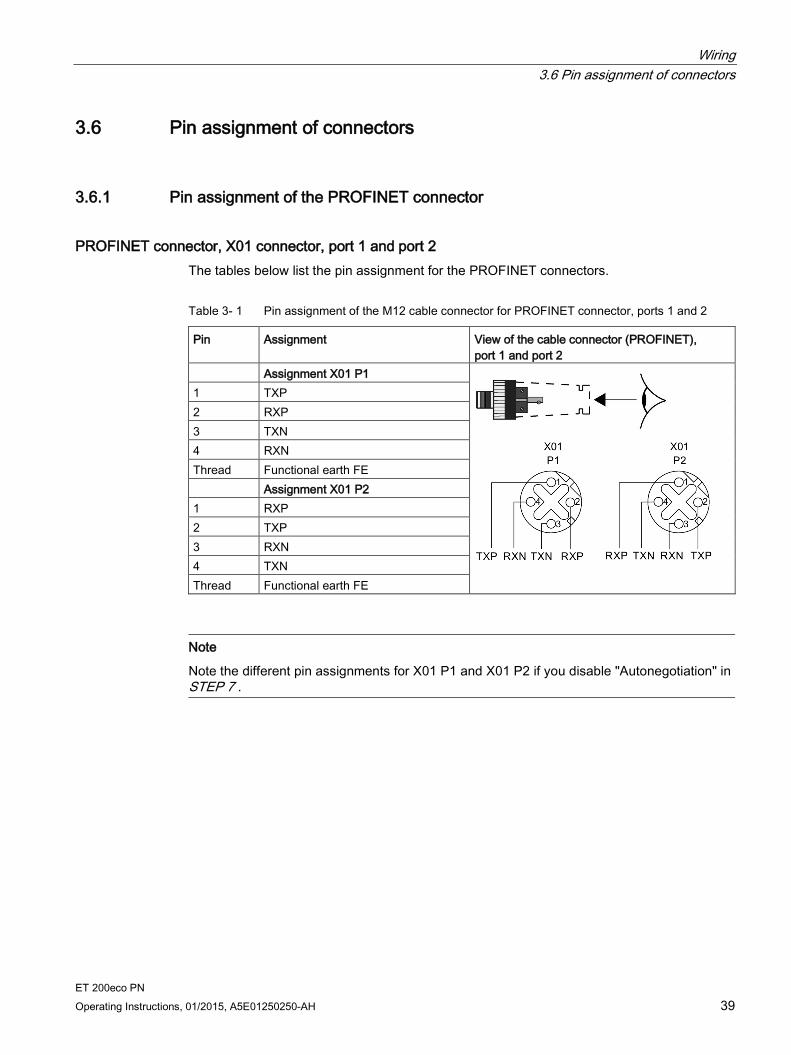
PROFINET connector, X01 connector, port 1 and port 2 The tables below list the pin assignment for the PROFINET connectors.
Table 3- 1 Pin assignment of the M12 cable connector for PROFINET connector, ports 1 and 2
Pin Assignment View of the cable connector (PROFINET), port 1 and port 2
Assignment X01 P1
1 TXP 2 RXP 3 TXN 4 RXN Thread Functional earth FE Assignment X01 P2 1 RXP 2 TXP 3 RXN 4 TXN Thread Functional earth FE
Note
Note the different pin assignments for X01 P1 and X01 P2 if you disable "Autonegotiation" in STEP 7 .

Wiring 3.6 Pin assignment of connectors
ET 200eco PN 40 Operating Instructions, 01/2015, A5E01250250-AH
3.6.2 Pin assignment for feeding and looping the voltage
Cable connector for supply voltage infeed, X03 connector The table below lists the pin assignment for the supply voltage infeed.
Table 3- 2 Pin assignment of the M12 cable connector for the supply voltage infeed
Pin Assignment View of the cable connector (wiring side)
1 Supply voltage 1L+ (non-switched)
2 Ground 2M (switched) 3 Ground 1M (non-switched) 4 Supply voltage 2L+ (switched) 5 Reserved
Wiring 3.6 Pin assignment of connectors
ET 200eco PN Operating Instructions, 01/2015, A5E01250250-AH 41
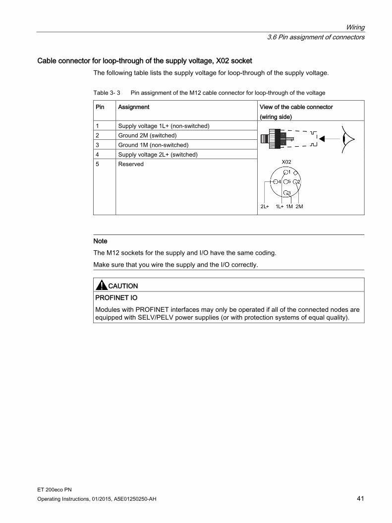
Cable connector for loop-through of the supply voltage, X02 socket The following table lists the supply voltage for loop-through of the supply voltage.
Table 3- 3 Pin assignment of the M12 cable connector for loop-through of the voltage
Pin Assignment View of the cable connector (wiring side)
1 Supply voltage 1L+ (non-switched)
2 Ground 2M (switched) 3 Ground 1M (non-switched) 4 Supply voltage 2L+ (switched) 5 Reserved
Note
The M12 sockets for the supply and I/O have the same coding.
Make sure that you wire the supply and the I/O correctly.
CAUTION
PROFINET IO
Modules with PROFINET interfaces may only be operated if all of the connected nodes are equipped with SELV/PELV power supplies (or with protection systems of equal quality).
Wiring 3.6 Pin assignment of connectors
ET 200eco PN 42 Operating Instructions, 01/2015, A5E01250250-AH
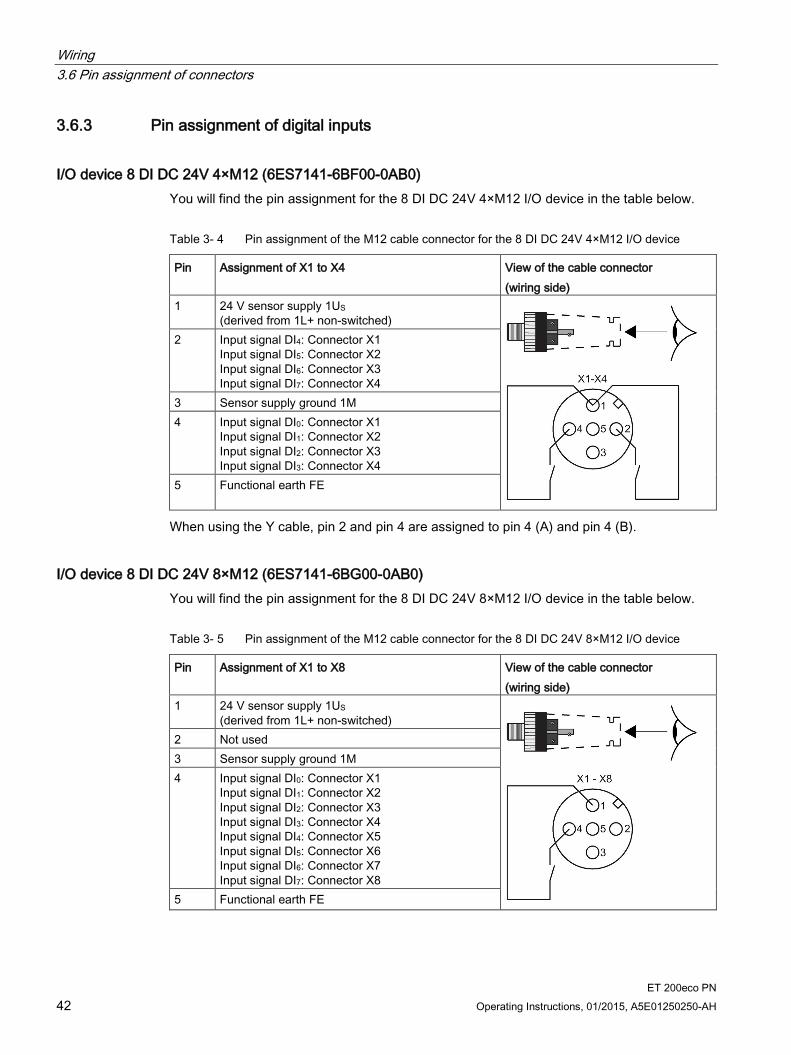
3.6.3 Pin assignment of digital inputs
I/O device 8 DI DC 24V 4×M12 (6ES7141-6BF00-0AB0) You will find the pin assignment for the 8 DI DC 24V 4×M12 I/O device in the table below.
Table 3- 4 Pin assignment of the M12 cable connector for the 8 DI DC 24V 4×M12 I/O device
Pin Assignment of X1 to X4 View of the cable connector (wiring side)
1 24 V sensor supply 1US (derived from 1L+ non-switched)
2 Input signal DI4: Connector X1 Input signal DI5: Connector X2 Input signal DI6: Connector X3 Input signal DI7: Connector X4
3 Sensor supply ground 1M 4 Input signal DI0: Connector X1
Input signal DI1: Connector X2 Input signal DI2: Connector X3 Input signal DI3: Connector X4
5 Functional earth FE
When using the Y cable, pin 2 and pin 4 are assigned to pin 4 (A) and pin 4 (B).
I/O device 8 DI DC 24V 8×M12 (6ES7141-6BG00-0AB0) You will find the pin assignment for the 8 DI DC 24V 8×M12 I/O device in the table below.
Table 3- 5 Pin assignment of the M12 cable connector for the 8 DI DC 24V 8×M12 I/O device
Pin Assignment of X1 to X8 View of the cable connector (wiring side)
1 24 V sensor supply 1US (derived from 1L+ non-switched)
2 Not used 3 Sensor supply ground 1M 4 Input signal DI0: Connector X1
Input signal DI1: Connector X2 Input signal DI2: Connector X3 Input signal DI3: Connector X4 Input signal DI4: Connector X5 Input signal DI5: Connector X6 Input signal DI6: Connector X7 Input signal DI7: Connector X8
5 Functional earth FE

Wiring 3.6 Pin assignment of connectors
ET 200eco PN Operating Instructions, 01/2015, A5E01250250-AH 43
I/O device 16 DI DC 24V 8×M12 (6ES7141-6BH00-0BA0) You will find the pin assignment for the 16 DI DC 24V 8×M12 I/O device in the table below.
Table 3- 6 Pin assignment of the M12 cable connector for the 16 DI DC 24V 8×M12 I/O device
Pin Assignment of X1 to X8 View of the cable connector (wiring side)
1 24 V sensor supply 1US (derived from 1L+ non-switched)
2 Input signal DI8: Connector X1 Input signal DI9: Connector X2 Input signal DI10: Connector X3 Input signal DI11: Connector X4 Input signal DI12: Connector X5 Input signal DI13: Connector X6 Input signal DI14: Connector X7 Input signal DI15: Connector X8
3 Sensor supply ground 1M 4 Input signal DI0: Connector X1
Input signal DI1: Connector X2 Input signal DI2: Connector X3 Input signal DI3: Connector X4 Input signal DI4: Connector X5 Input signal DI5: Connector X6 Input signal DI6: Connector X7 Input signal DI7: Connector X8
5 Functional earth FE
When using the Y cable, pin 2 and pin 4 are assigned to pin 4 (A) and pin 4 (B).
Note
The M12 sockets for the supply and I/O have the same coding.
Make sure that you wire the supply and the I/O correctly.
Wiring 3.6 Pin assignment of connectors
ET 200eco PN 44 Operating Instructions, 01/2015, A5E01250250-AH
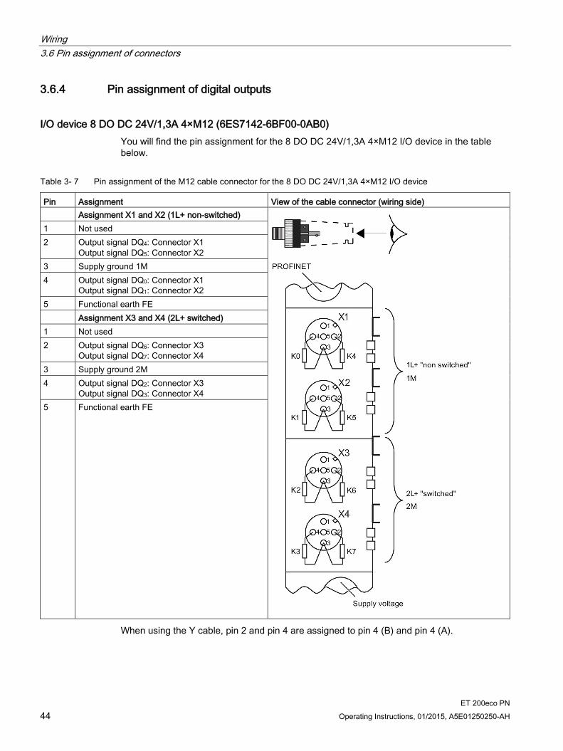
3.6.4 Pin assignment of digital outputs
I/O device 8 DO DC 24V/1,3A 4×M12 (6ES7142-6BF00-0AB0) You will find the pin assignment for the 8 DO DC 24V/1,3A 4×M12 I/O device in the table below.
Table 3- 7 Pin assignment of the M12 cable connector for the 8 DO DC 24V/1,3A 4×M12 I/O device
Pin Assignment View of the cable connector (wiring side) Assignment X1 and X2 (1L+ non-switched)
1 Not used 2 Output signal DQ4: Connector X1
Output signal DQ5: Connector X2 3 Supply ground 1M 4 Output signal DQ0: Connector X1
Output signal DQ1: Connector X2 5 Functional earth FE Assignment X3 and X4 (2L+ switched) 1 Not used 2 Output signal DQ6: Connector X3
Output signal DQ7: Connector X4 3 Supply ground 2M 4 Output signal DQ2: Connector X3
Output signal DQ3: Connector X4 5 Functional earth FE
When using the Y cable, pin 2 and pin 4 are assigned to pin 4 (B) and pin 4 (A).
Wiring 3.6 Pin assignment of connectors
ET 200eco PN Operating Instructions, 01/2015, A5E01250250-AH 45
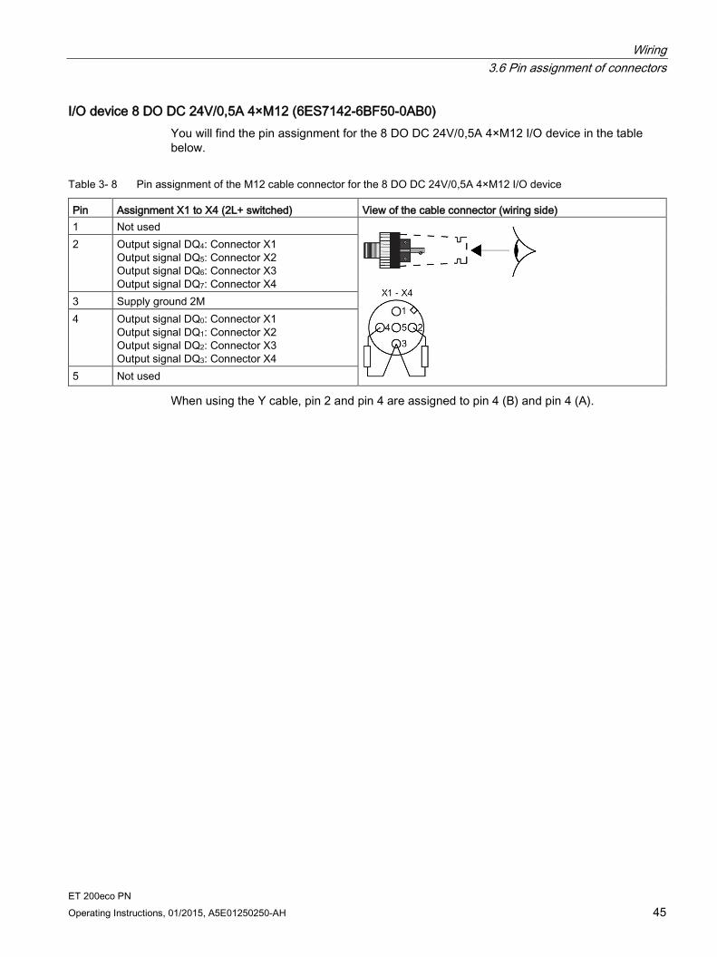
I/O device 8 DO DC 24V/0,5A 4×M12 (6ES7142-6BF50-0AB0) You will find the pin assignment for the 8 DO DC 24V/0,5A 4×M12 I/O device in the table below.
Table 3- 8 Pin assignment of the M12 cable connector for the 8 DO DC 24V/0,5A 4×M12 I/O device
Pin Assignment X1 to X4 (2L+ switched) View of the cable connector (wiring side) 1 Not used
2 Output signal DQ4: Connector X1 Output signal DQ5: Connector X2 Output signal DQ6: Connector X3 Output signal DQ7: Connector X4
3 Supply ground 2M 4 Output signal DQ0: Connector X1
Output signal DQ1: Connector X2 Output signal DQ2: Connector X3 Output signal DQ3: Connector X4
5 Not used
When using the Y cable, pin 2 and pin 4 are assigned to pin 4 (B) and pin 4 (A).
Wiring 3.6 Pin assignment of connectors
ET 200eco PN 46 Operating Instructions, 01/2015, A5E01250250-AH
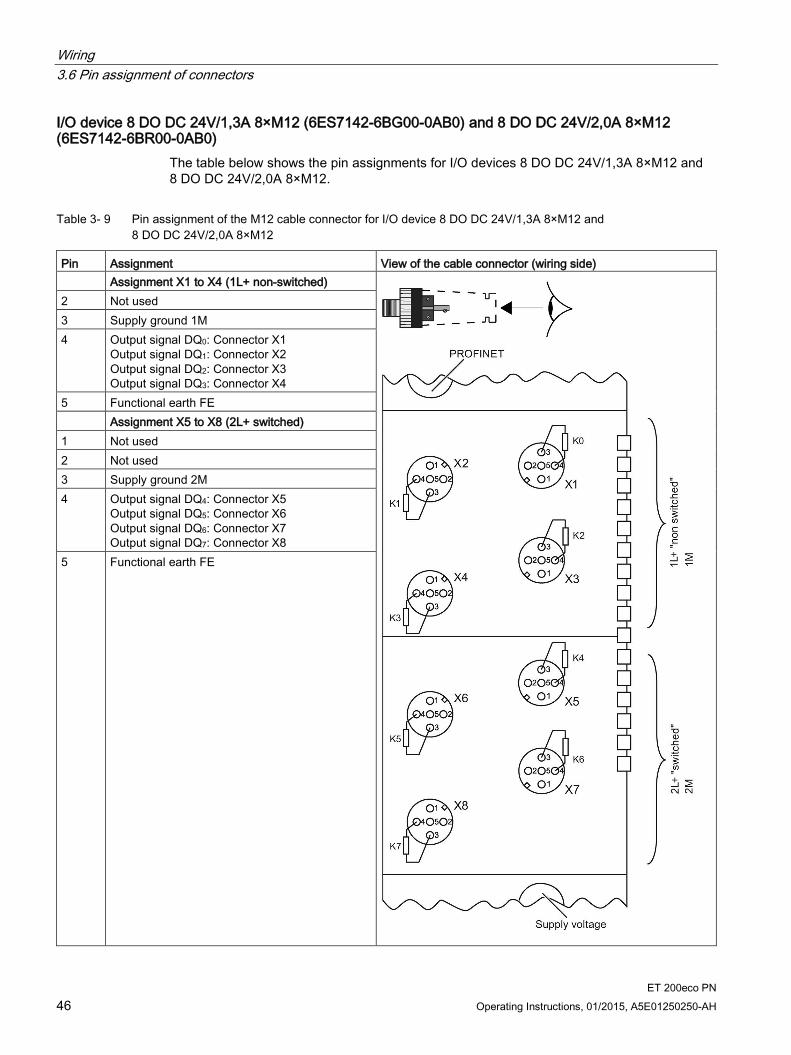
I/O device 8 DO DC 24V/1,3A 8×M12 (6ES7142-6BG00-0AB0) and 8 DO DC 24V/2,0A 8×M12 (6ES7142-6BR00-0AB0)
The table below shows the pin assignments for I/O devices 8 DO DC 24V/1,3A 8×M12 and 8 DO DC 24V/2,0A 8×M12.
Table 3- 9 Pin assignment of the M12 cable connector for I/O device 8 DO DC 24V/1,3A 8×M12 and 8 DO DC 24V/2,0A 8×M12
Pin Assignment View of the cable connector (wiring side) Assignment X1 to X4 (1L+ non-switched)
2 Not used 3 Supply ground 1M 4 Output signal DQ0: Connector X1
Output signal DQ1: Connector X2 Output signal DQ2: Connector X3 Output signal DQ3: Connector X4
5 Functional earth FE Assignment X5 to X8 (2L+ switched) 1 Not used 2 Not used 3 Supply ground 2M 4 Output signal DQ4: Connector X5
Output signal DQ5: Connector X6 Output signal DQ6: Connector X7 Output signal DQ7: Connector X8
5 Functional earth FE
Wiring 3.6 Pin assignment of connectors
ET 200eco PN Operating Instructions, 01/2015, A5E01250250-AH 47
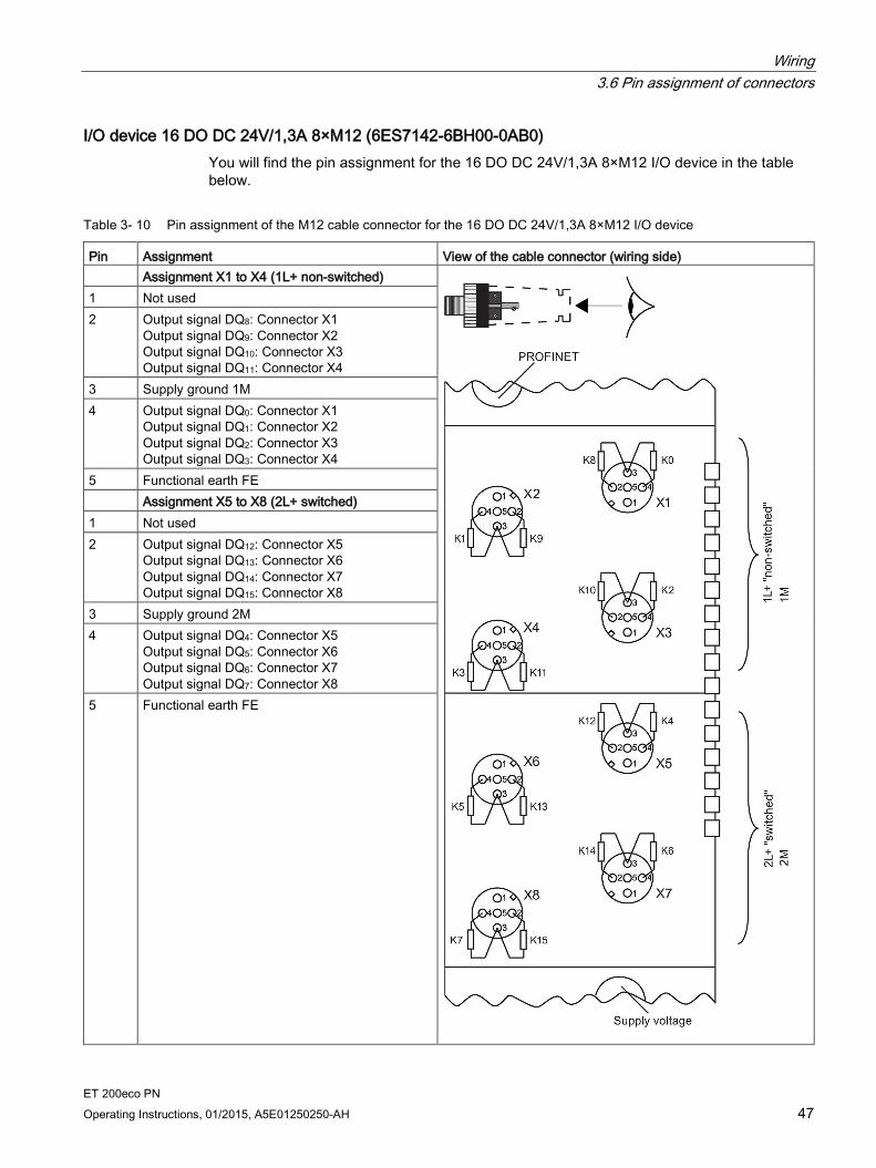
I/O device 16 DO DC 24V/1,3A 8×M12 (6ES7142-6BH00-0AB0) You will find the pin assignment for the 16 DO DC 24V/1,3A 8×M12 I/O device in the table below.
Table 3- 10 Pin assignment of the M12 cable connector for the 16 DO DC 24V/1,3A 8×M12 I/O device
Pin Assignment View of the cable connector (wiring side) Assignment X1 to X4 (1L+ non-switched)
1 Not used 2 Output signal DQ8: Connector X1
Output signal DQ9: Connector X2 Output signal DQ10: Connector X3 Output signal DQ11: Connector X4
3 Supply ground 1M 4 Output signal DQ0: Connector X1
Output signal DQ1: Connector X2 Output signal DQ2: Connector X3 Output signal DQ3: Connector X4
5 Functional earth FE Assignment X5 to X8 (2L+ switched) 1 Not used 2 Output signal DQ12: Connector X5
Output signal DQ13: Connector X6 Output signal DQ14: Connector X7 Output signal DQ15: Connector X8
3 Supply ground 2M 4 Output signal DQ4: Connector X5
Output signal DQ5: Connector X6 Output signal DQ6: Connector X7 Output signal DQ7: Connector X8
5 Functional earth FE

Wiring 3.6 Pin assignment of connectors
ET 200eco PN 48 Operating Instructions, 01/2015, A5E01250250-AH
When using the Y cable, pin 2 and pin 4 are assigned to pin 4 (B) and pin 4 (A).
Note
The M12 sockets for the supply and I/O have the same coding.
Make sure that you wire the supply and the I/O correctly.
3.6.5 Pin assignment for parameterizable digital input/digital output
I/O device 8 DIO DC 24V/1,3A 8×M12 (6ES7147-6BG00-0AB0) You will find the pin assignment for the 8 DIO DC 24V/1,3A 8×M12 I/O device in the table below.
Table 3- 11 Pin assignment of the M12 cable connector for the 8 DIO DC 24V/1,3A 8×M12 I/O device
Pin Assignment View of the cable connector (wiring side) Assignment X1 to X4 (1L+ non-switched)
Input
Output
1* 24 V sensor supply 1US (derived from 1L+ non-switched)
2 Not used 3 Supply ground 1M 4 Input / output signal DIQ0: Connector X1
Input/output signal DIQ1: Connector X2 Input/output signal DIQ2: Connector X3 Input/output signal DIQ3: Connector X4
5 Functional earth FE Assignment X5 to X8 (2L+ switched) 1 24 V sensor supply 2US
(derived from 2L+ switched) 2 Not used 3 Supply ground 2M 4 Input / output signal DIQ4: Connector X5
Input/output signal DIQ5: Connector X6 Input/output signal DIQ6: Connector X7 Input/output signal DIQ7: Connector X8
5 Functional earth FE
* The sensor supply is only available when the corresponding channel is parameterized as an "Input".

Wiring 3.6 Pin assignment of connectors
ET 200eco PN Operating Instructions, 01/2015, A5E01250250-AH 49
3.6.6 Pin assignment for IO-Link Master
IO-Link Master 4 IO-L + 8 DI + 4 DO DC 24V/1,3A 8×M12 (6ES7148-6JA00-0AB0) The following tables contain the pin assignments for the IO-Link Master 4 IO-L + 8 DI + 4 DO DC 24V/1,3A 8×M12.
Table 3- 12 Pin assignment for IO-Link Master and digital inputs
Pin Assignment of X1 to X4 View of the cable connector (wiring side)
1 24 V sensor supply 1US (derived from 1L+ non-switched)
2 Input signal DI0: Connector X1 Input signal DI1: Connector X2 Input signal DI2: Connector X3 Input signal DI3: Connector X4
3 Sensor supply ground 1M 4 IO-Link Master
Port 1: Connector X1 Port 2: Connector X2 Port 3: Connector X3 Port 4: Connector X4
5 Not used
Table 3- 13 Pin assignment for digital inputs
Pin Assignment of X5 and X6 View of the cable connector (wiring side)
1 24 V sensor supply 1US (derived from 1L+ non-switched)
2 Input signal DI5: Connector X5 Input signal DI7: Connector X6
3 Sensor supply ground 1M 4 Input signal DI4: Connector X5
Input signal DI6: Connector X6 5 Functional earth FE
Wiring 3.6 Pin assignment of connectors
ET 200eco PN 50 Operating Instructions, 01/2015, A5E01250250-AH
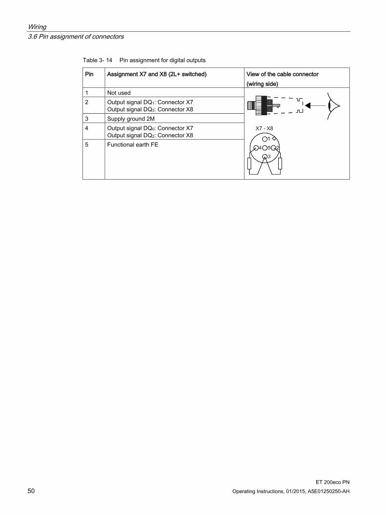
Table 3- 14 Pin assignment for digital outputs
Pin Assignment X7 and X8 (2L+ switched) View of the cable connector (wiring side)
1 Not used
2 Output signal DQ1: Connector X7 Output signal DQ3: Connector X8
3 Supply ground 2M 4 Output signal DQ0: Connector X7
Output signal DQ2: Connector X8 5 Functional earth FE

Wiring 3.6 Pin assignment of connectors
ET 200eco PN Operating Instructions, 01/2015, A5E01250250-AH 51
3.6.7 Pin assignment for analog inputs
I/O device 8 AI 4 U/I + 4 RTD/TC 8×M12 (6ES7144-6KD00-0AB0) You will find the pin assignment for the 8 AI 4 U/I + 4 RTD/TC 8×M12 I/O device in the table below.
Table 3- 15 Pin assignment for voltage and current for the 8 AI 4 U/I + 4 RTD/TC 8×M12 I/O device
Pin Assignment of X1, X3, X5, X7 View of the cable connector (wiring side)
1 24 V sensor supply 1US (derived from 1L+ non-switched)
Voltage
Current 4-wire transducer
2-wire transducer
2 Connector X1: Input signal M0+ Connector X3: Input signal M1+ Connector X5: Input signal M2+ Connector X7: Input signal M3+
3 Sensor supply ground 1M 4 Connector X1: Input signal M0-
Connector X3: Input signal M1- Connector X5: Input signal M2- Connector X7: Input signal M3-
5 Functional earth FE
① 4- or 5-core shielded copper cable ② 3-, 4-, or 5-core shielded copper cable

Wiring 3.6 Pin assignment of connectors
ET 200eco PN 52 Operating Instructions, 01/2015, A5E01250250-AH
Table 3- 16 Pin assignment for RTD for the 8 AI 4 U/I + 4 RTD/TC 8×M12 I/O device
Pin Assignment of X2, X4, X6, X8 (for RTD) View of the cable connector (wiring side)
Connector X2: Input signal 4 Connector X4: Input signal 5 Connector X6: Input signal 6 Connector X8: Input signal 7
4-conductor
1 Constant current line positive ICn+ 2 Measurement cable positive Mn+ 3 Constant current line negative ICn- 4 Measurement cable negative Mn- 5 Functional earth FE
3-conductor
1 Constant current line positive ICn+ 2 Measurement cable positive Mn+ 3 Measurement cable negative Mn- and constant
current line negative ICn- 5 Functional earth FE
2-conductor
1 Measurement cable positive Mn+ and constant current line positive ICn+
3 Measurement cable negative Mn- and constant current line negative ICn-
5 Functional earth FE
① 4- or 5-core shielded copper cable ② 3-, 4-, or 5-core shielded copper cable
Wiring 3.6 Pin assignment of connectors
ET 200eco PN Operating Instructions, 01/2015, A5E01250250-AH 53
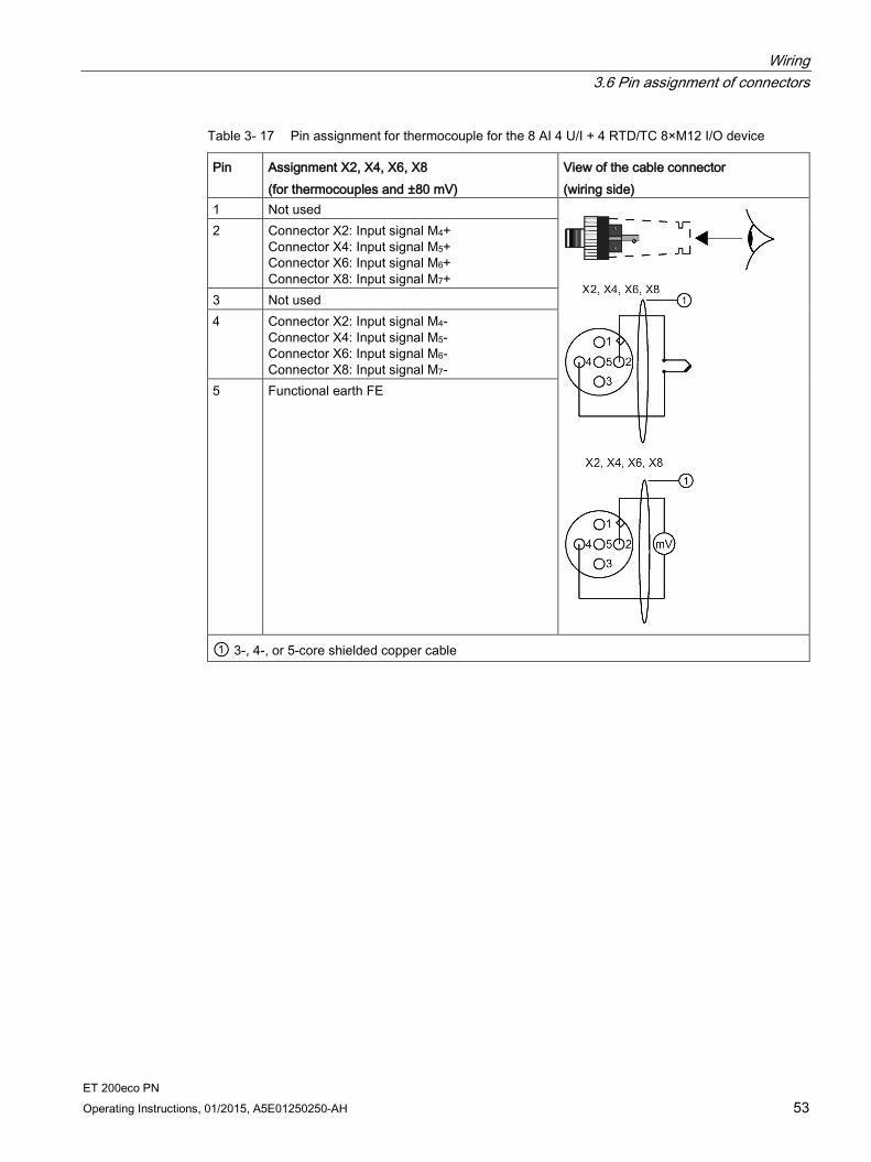
Table 3- 17 Pin assignment for thermocouple for the 8 AI 4 U/I + 4 RTD/TC 8×M12 I/O device
Pin Assignment X2, X4, X6, X8 (for thermocouples and ±80 mV)
View of the cable connector (wiring side)
1 Not used
2 Connector X2: Input signal M4+ Connector X4: Input signal M5+ Connector X6: Input signal M6+ Connector X8: Input signal M7+
3 Not used 4 Connector X2: Input signal M4-
Connector X4: Input signal M5- Connector X6: Input signal M6- Connector X8: Input signal M7-
5 Functional earth FE
① 3-, 4-, or 5-core shielded copper cable
Wiring 3.6 Pin assignment of connectors
ET 200eco PN 54 Operating Instructions, 01/2015, A5E01250250-AH
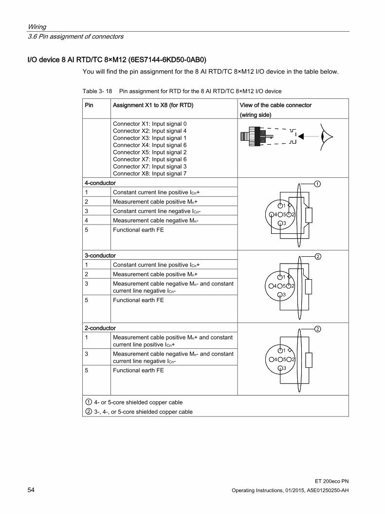
I/O device 8 AI RTD/TC 8×M12 (6ES7144-6KD50-0AB0) You will find the pin assignment for the 8 AI RTD/TC 8×M12 I/O device in the table below.
Table 3- 18 Pin assignment for RTD for the 8 AI RTD/TC 8×M12 I/O device
Pin Assignment X1 to X8 (for RTD) View of the cable connector (wiring side)
Connector X1: Input signal 0 Connector X2: Input signal 4 Connector X3: Input signal 1 Connector X4: Input signal 6 Connector X5: Input signal 2 Connector X7: Input signal 6 Connector X7: Input signal 3 Connector X8: Input signal 7
4-conductor
1 Constant current line positive ICn+ 2 Measurement cable positive Mn+ 3 Constant current line negative ICn- 4 Measurement cable negative Mn- 5 Functional earth FE
3-conductor
1 Constant current line positive ICn+ 2 Measurement cable positive Mn+ 3 Measurement cable negative Mn- and constant
current line negative ICn- 5 Functional earth FE
2-conductor
1 Measurement cable positive Mn+ and constant current line positive ICn+
3 Measurement cable negative Mn- and constant current line negative ICn-
5 Functional earth FE
① 4- or 5-core shielded copper cable ② 3-, 4-, or 5-core shielded copper cable

Wiring 3.6 Pin assignment of connectors
ET 200eco PN Operating Instructions, 01/2015, A5E01250250-AH 55
Table 3- 19 Pin assignment for thermocouple for the 8 AI RTD/TC 8×M12 I/O device
Pin Assignment of X1 to X8 (for thermocouples and ±80 mV)
View of the cable connector (wiring side)
1 Not used
2 Connector X1: Input signal M0+ Connector X2: Input signal M4+ Connector X3: Input signal M1+ Connector X4: Input signal M5+ Connector X5: Input signal M2+ Connector X6: Input signal M6+ Connector X7: Input signal M3+ Connector X8: Input signal M7+
3 Not used 4 Connector X1: Input signal M0-
Connector X2: Input signal M4- Connector X3: Input signal M1- Connector X4: Input signal M5- Connector X5: Input signal M2- Connector X6: Input signal M6- Connector X7: Input signal M3- Connector X8: Input signal M7-
5 Functional earth FE
① 3-, 4-, or 5-core shielded copper cable
Wiring 3.6 Pin assignment of connectors
ET 200eco PN 56 Operating Instructions, 01/2015, A5E01250250-AH
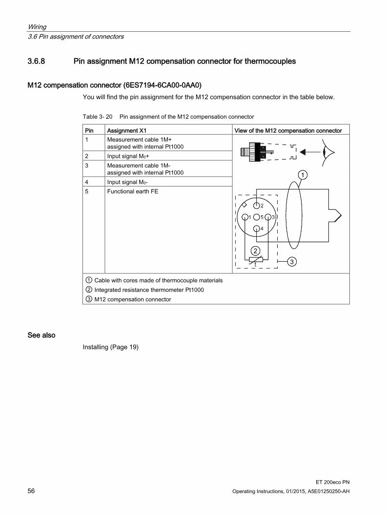
3.6.8 Pin assignment M12 compensation connector for thermocouples
M12 compensation connector (6ES7194-6CA00-0AA0) You will find the pin assignment for the M12 compensation connector in the table below.
Table 3- 20 Pin assignment of the M12 compensation connector
Pin Assignment X1 View of the M12 compensation connector 1 Measurement cable 1M+
assigned with internal Pt1000
2 Input signal M0+ 3 Measurement cable 1M-
assigned with internal Pt1000 4 Input signal M0- 5 Functional earth FE
① Cable with cores made of thermocouple materials ② Integrated resistance thermometer Pt1000 ③ M12 compensation connector
See also Installing (Page 19)
Wiring 3.6 Pin assignment of connectors
ET 200eco PN Operating Instructions, 01/2015, A5E01250250-AH 57
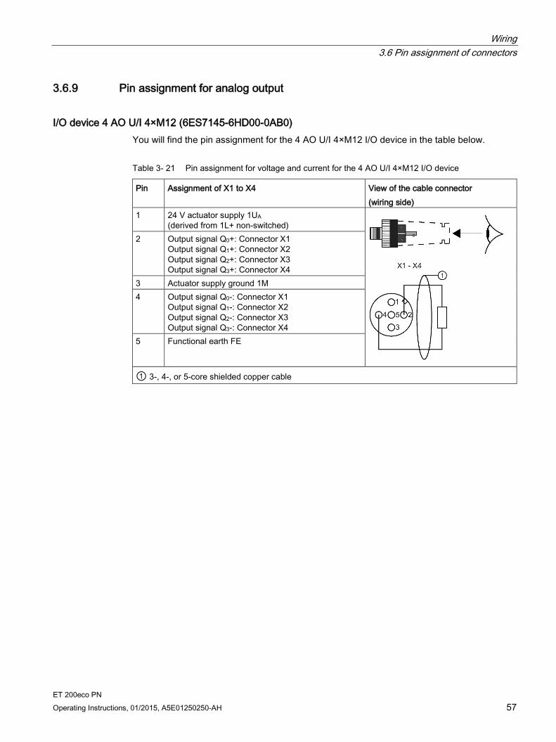
3.6.9 Pin assignment for analog output
I/O device 4 AO U/I 4×M12 (6ES7145-6HD00-0AB0) You will find the pin assignment for the 4 AO U/I 4×M12 I/O device in the table below.
Table 3- 21 Pin assignment for voltage and current for the 4 AO U/I 4×M12 I/O device
Pin Assignment of X1 to X4 View of the cable connector (wiring side)
1 24 V actuator supply 1UA (derived from 1L+ non-switched)
2 Output signal Q0+: Connector X1 Output signal Q1+: Connector X2 Output signal Q2+: Connector X3 Output signal Q3+: Connector X4
3 Actuator supply ground 1M 4 Output signal Q0-: Connector X1
Output signal Q1-: Connector X2 Output signal Q2-: Connector X3 Output signal Q3-: Connector X4
5 Functional earth FE
① 3-, 4-, or 5-core shielded copper cable

Wiring 3.7 Wiring the terminal block
ET 200eco PN 58 Operating Instructions, 01/2015, A5E01250250-AH
3.7 Wiring the terminal block
Tools required You need a medium-sized cross-tip screwdriver to screw on the terminal block and a slotted screwdriver to press down the insulation displacement terminals.
Wiring the connectors You do not have to strip the cables. They are striped automatically when you press down the insulation displacement terminals.
Figure 3-4 Wiring the terminal block
Wiring 3.7 Wiring the terminal block
ET 200eco PN Operating Instructions, 01/2015, A5E01250250-AH 59
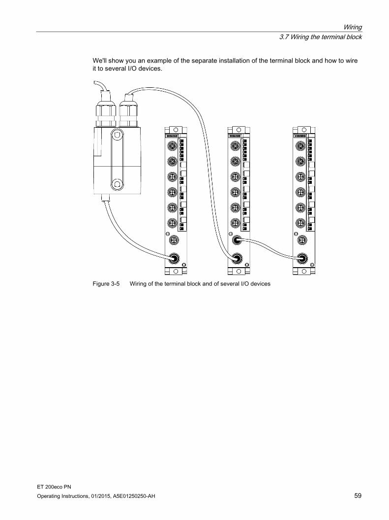
We'll show you an example of the separate installation of the terminal block and how to wire it to several I/O devices.
Figure 3-5 Wiring of the terminal block and of several I/O devices

Wiring 3.7 Wiring the terminal block
ET 200eco PN 60 Operating Instructions, 01/2015, A5E01250250-AH
You can tap a maximum load of 4 A from each supply voltage of the I/O device. You can loop-through the rest.
Figure 3-6 Principle of current distribution at the terminal block
Wiring 3.7 Wiring the terminal block
ET 200eco PN Operating Instructions, 01/2015, A5E01250250-AH 61
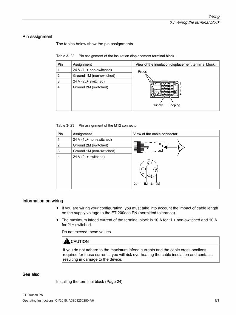
Pin assignment The tables below show the pin assignments.
Table 3- 22 Pin assignment of the insulation displacement terminal block.
Pin Assignment View of the insulation displacement terminal block: 1 24 V (1L+ non-switched)
2 Ground 1M (non-switched) 3 24 V (2L+ switched) 4 Ground 2M (switched)
Table 3- 23 Pin assignment of the M12 connector
Pin Assignment View of the cable connector 1 24 V (1L+ non-switched)
2 Ground 2M (switched) 3 Ground 1M (non-switched) 4 24 V (2L+ switched)
Information on wiring If you are wiring your configuration, you must take into account the impact of cable length
on the supply voltage to the ET 200eco PN (permitted tolerance).
The maximum infeed current of the terminal block is 10 A for 1L+ non-switched and 10 A for 2L+ switched.
Do not exceed these values.
CAUTION
If you do not adhere to the maximum infeed currents and the cable cross-sections required for these currents, you will risk overheating the cable insulation and contacts resulting in damage to the device.
See also Installing the terminal block (Page 24)

Wiring 3.8 Wiring the voltage distributor
ET 200eco PN 62 Operating Instructions, 01/2015, A5E01250250-AH
3.8 Wiring the voltage distributor
Wiring the connectors We use an example to show the configuration of the PD DC 24V 1×7/8" 4×M12 voltage distributor with connected I/O devices.
Figure 3-7 Wiring the voltage distributor
Wiring 3.8 Wiring the voltage distributor
ET 200eco PN Operating Instructions, 01/2015, A5E01250250-AH 63
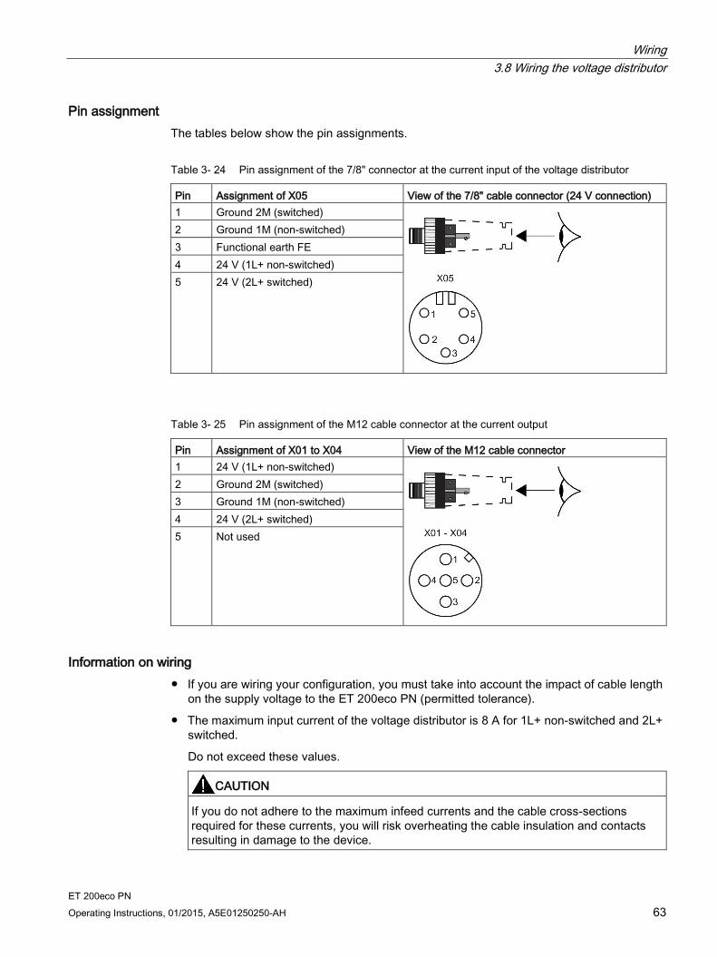
Pin assignment The tables below show the pin assignments.
Table 3- 24 Pin assignment of the 7/8" connector at the current input of the voltage distributor
Pin Assignment of X05 View of the 7/8" cable connector (24 V connection) 1 Ground 2M (switched)
2 Ground 1M (non-switched) 3 Functional earth FE 4 24 V (1L+ non-switched) 5 24 V (2L+ switched)
Table 3- 25 Pin assignment of the M12 cable connector at the current output
Pin Assignment of X01 to X04 View of the M12 cable connector 1 24 V (1L+ non-switched)
2 Ground 2M (switched) 3 Ground 1M (non-switched) 4 24 V (2L+ switched) 5 Not used
Information on wiring If you are wiring your configuration, you must take into account the impact of cable length
on the supply voltage to the ET 200eco PN (permitted tolerance).
The maximum input current of the voltage distributor is 8 A for 1L+ non-switched and 2L+ switched.
Do not exceed these values.
CAUTION
If you do not adhere to the maximum infeed currents and the cable cross-sections required for these currents, you will risk overheating the cable insulation and contacts resulting in damage to the device.
Wiring 3.9 Looping PROFINET and the supply voltage
ET 200eco PN 64 Operating Instructions, 01/2015, A5E01250250-AH
3.9 Looping PROFINET and the supply voltage
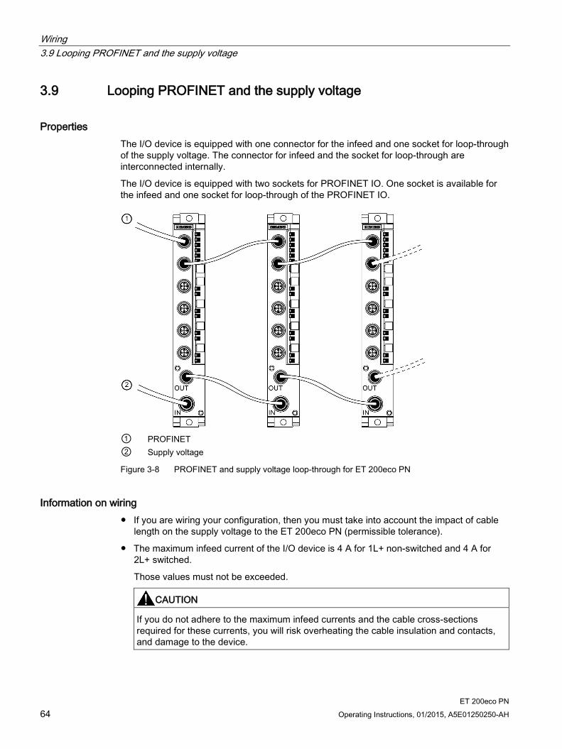
Properties The I/O device is equipped with one connector for the infeed and one socket for loop-through of the supply voltage. The connector for infeed and the socket for loop-through are interconnected internally.
The I/O device is equipped with two sockets for PROFINET IO. One socket is available for the infeed and one socket for loop-through of the PROFINET IO.
① PROFINET ② Supply voltage
Figure 3-8 PROFINET and supply voltage loop-through for ET 200eco PN
Information on wiring If you are wiring your configuration, then you must take into account the impact of cable
length on the supply voltage to the ET 200eco PN (permissible tolerance).
The maximum infeed current of the I/O device is 4 A for 1L+ non-switched and 4 A for 2L+ switched.
Those values must not be exceeded.
CAUTION
If you do not adhere to the maximum infeed currents and the cable cross-sections required for these currents, you will risk overheating the cable insulation and contacts, and damage to the device.

ET 200eco PN Operating Instructions, 01/2015, A5E01250250-AH 65
Configuring 4 4.1 Configuring ET 200eco PN
Requirements You need STEP 7 as of version V5.4, SP4 and possibly HSP.
Introduction ET 200eco PN is included in the hardware catalog of HW Config after the start of STEP 7.
Procedure 1. Start SIMATIC Manager.
2. Create a new project.
3. Configure the ET 200eco PN with HW Config.
4. Double-click on the technology module at slot 1 of the ET 200eco PN in the configuration table and set the parameters.
5. Save the configuration, or download it to the IO Controller.
Prerequisite for the GSD file You will need a GSD file, available for download from the Internet (http://support.automation.siemens.com/WW/view/en/19698639/133100).
ET 200eco PN family: gsdml-v2.2-siemens-et200eco"date format yyyymmdd".xml
Configuring ET 200eco PN on PROFINET IO using STEP 7 1. Start STEP 7 and call up the Options > Install New GSD File menu command in
HW Config.
2. In the next dialog box, select the GSD file to install, and confirm with "OK". Result: ET 200eco PN is displayed in the hardware catalog, PROFINET IO folder.
3. The rest of the procedure is as described in the Programming with STEP 7 (http://support.automation.siemens.com/WW/view/en/18652056) manual.
See also For further information, refer to the STEP 7 online help.

Configuring 4.2 Configuring the IO-Link Master
ET 200eco PN 66 Operating Instructions, 01/2015, A5E01250250-AH
4.2 Configuring the IO-Link Master
Requirements Configuration of the IO-Link Master takes place in two steps:
1. You need STEP 7 as of version V5.4 + SP5 + HSP188 for the IO-Link Master.
2. Configure the connected IO-Link Devices, sensors, and actuators with the Port Configurator tool (S7-PCT).
Configuring the IO-Link Master with HW Config 1. Start the SIMATIC Manager and configure the project as described in the STEP 7 online
help.
2. Drag the IO-Link Master from the HW catalog PROFINET IO > ET 200eco PN > IO Link > 4 IO-L + 8 DI + 4 DO DC24V/1.3A 8×M12 V6.1.
You can freely choose the address space in the Properties > Addresses field for each slot of the IO-Link Master. Additional information on possible configurations is available in the chapter I/O address space (Page 234).
3. Assign the IO-Link Master parameters. You can assign the parameters separately for a functional unit:
– The PROFINET IO parameters are accessed by double-clicking Slot 0.
– The IO-Link parameters are accessed by double-clicking Slot 1.
– The 8 digital input and 4 digital output parameters are accessed by double-clicking Slot 2.
Configuring the IO-Link Devices using "Configure IO-Link" 1. Select Slot 1 "4 IO-L" from the configuration table of the I/O device IO-Link Master.
2. Right-click and select "Configure IO-Link" in the following shortcut menu.
Result: S7-PCT is started.
3. Now start with the parameter assignment of the IO-Link Devices, sensors, and actuators.
Additional information is available in the S7-PCT online help.

Configuring 4.2 Configuring the IO-Link Master
ET 200eco PN Operating Instructions, 01/2015, A5E01250250-AH 67
Configuring the IO-Link Master with GSD file 1. Install the GSD file in HW Config. The GSD file is available on the Internet.
2. Select the IO-Link Master I/O device in the hardware catalog of HW Config.
3. You can freely choose the address space in the Properties > Addresses field for each slot of the IO-Link Master. In contrast to HSP configuration, the address space on Slot 1 "4 IO-L" is set permanently to 32 byte inputs and outputs. Additional information on possible configurations is available in the chapter I/O address space (Page 234).
4. Assign the IO-Link Master parameters. You can assign the parameters separately for a functional unit:
– The PROFINET IO parameters are accessed by double-clicking Slot 0.
– The IO-Link parameters are accessed by double-clicking Slot 1.
– The 8 digital input and 4 digital output parameters are accessed by double-clicking Slot 2.
Configuring the IO-Link Devices using S7-PCT 1. Select Slot 1 "4 IO-L" from the configuration table of the I/O device IO-Link Master.
2. Right-click and select "Start Device Tool" in the following shortcut menu.
Result: S7-PCT is started.
3. Now start with the parameter assignment of the IO-Link Devices, sensors, and actuators.
Additional information is available in the S7-PCT online help.
Behavior in non-parameterized status and after "Reset to factory settings" All ports of the IO-Link Master are deactivated.
All user data are equal to 0.
All bits of the value status are set to "invalid."
The maintenance data 1 to 3 are deleted.
Configuring 4.3 Device names for ET 200eco PN
ET 200eco PN 68 Operating Instructions, 01/2015, A5E01250250-AH
4.3 Device names for ET 200eco PN
Introduction Every PROFINET IO device is assigned a unique device ID (MAC address) before it leaves the factory.
Each ET 200eco PN IO Device is addressed based on its device name during configuration and in the user program.
You will find detailed information on addressing in PROFINET IO in the the SIMATIC PROFINET system description (http://support.automation.siemens.com/WW/view/en/19292127) System Manual.
Requirements An online PROFINET connection from the programming device to the IO Device is
required for assigning the device name to the IO Device.
The IO device is configured and an IP address assigned in HW Config.
Assigning device names 1. Switch on the supply voltages for the ET 200eco PN.
2. Open the "Properties - ET 200eco PN" window in HW Config. Enter the device name for the IO Device and confirm your entry with "OK".
3. Select PLC > Ethernet > Assign Device Name in HW Config.
4. Click on "Assign Name" in the "Assign Device Name" window.
Result The device name is saved internally in the ET 200eco PN.
Node flash test The "Assign device name" dialog box displays all IO Devices used. Compare the MAC address of the device with the MAC address displayed and then select the correct IO Device.
The identification of IO Devices in a plant is facilitated by a node flash test. The flash test is activated as follows:
1. Select one of the displayed IO Devices from the "Assign device name" dialog box.
2. Select the flashing period.
3. Click the "Flash on" button.
The LINK LEDs flash on the selected IO Device.

Configuring 4.4 Ports of ET 200eco PN
ET 200eco PN Operating Instructions, 01/2015, A5E01250250-AH 69
Detailed information For additional information, refer to the STEP 7 Online Help and the SIMATIC PROFINET system description (http://support.automation.siemens.com/WW/view/en/19292127) System Manual.
4.4 Ports of ET 200eco PN
Introduction The ET 200eco PN can diagnose 2 ports: X01 P1 and X01 P2.
Requirements The ports must have been configured in HW Config.
Port diagnostics must have been enabled.
Configuring the ports in HW Config Configure both ports in the "Properties of ET 200eco PN" dialog box of HW Config:
"Addresses" tab: Diagnostic address of the relevant port.
"Topology" tab:
"Options" tab:
To enable port diagnostics, select the following "Connection" setting at "Transmission Medium/Duplex": "Automatic Settings (monitor)".
See also See the STEP 7 Online Help.

Configuring 4.5 Isochronous real-time communication
ET 200eco PN 70 Operating Instructions, 01/2015, A5E01250250-AH
4.5 Isochronous real-time communication
Isochronous real-time communication Synchronized transmission method for the cyclic exchange of IRT data between PROFINET devices. A reserved bandwidth is available within the send cycle for IRT IO data. The reserved bandwidth ensures that IRT data can be transferred at reserved synchronized intervals, without being influence by other higher network loads (e.g., TCP/P communication, or additional real-time communication).
IRT option "high flexibility":
Maximum flexibility in planning and extending the system. It is not necessary to configure the topology.
IRT-option "high performance" (not for IO-Link-Master):
Topological configuration is required (starting with STEP 7 V5.5).
Note With the use of the IO controller as a Sync-Master at IRT communication with the IRT option "high performance", the following must be observed:
We recommend also operating the IO controller as a Sync-Master if you configure the IRT communication with the option "high performance".
Otherwise, IRT and RT configured IO devices may fail if the Sync-Master fails.
Detailed information For further information, see the SIMATIC PROFINET system description (http://support.automation.siemens.com/WW/view/en/19292127) System Manual and the Migration from PROFIBUS DP to PROFINET IO (http://support.automation.siemens.com/WW/view/en/19289930) Programming Manual.
Configuring 4.6 Prioritized startup
ET 200eco PN Operating Instructions, 01/2015, A5E01250250-AH 71
4.6 Prioritized startup
Prioritized startup Prioritized startup denotes PROFINET functionality for accelerating the startup of IO Devices for RT and IRT communication within a PROFINET IO system.
The function reduces the time that the correspondingly configured IO Devices require to recover the cyclic exchange of user data in the following situations:
After power has returned
After station recovery
After activation of IO Devices
Detailed information For further information, see the SIMATIC PROFINET system description (http://support.automation.siemens.com/WW/view/en/19292127) System Manual and the Migration from PROFIBUS DP to PROFINET IO (http://support.automation.siemens.com/WW/view/en/19289930) Programming Manual.
4.7 Device replacement without programming device
Device replacement without programming device IO Devices having this function can be replaced easily:
The device name does not have to be assigned using the programming device.
Instead of the programming device, the IO Controller now assigns the device name to the replacement IO Device. The IO Controller uses the configured topology and the correlations derived from the IO Devices. The configured target topology must agree with the actual topology.
IO Devices that have already been in operation must be reset to factory settings before before being put back into operation.
Detailed information For further information, see the SIMATIC PROFINET system description (http://support.automation.siemens.com/WW/view/en/19292127) System Manual and the Migration from PROFIBUS DP to PROFINET IO (http://support.automation.siemens.com/WW/view/en/19289930) Programming Manual.
Configuring 4.8 Media redundancy
ET 200eco PN 72 Operating Instructions, 01/2015, A5E01250250-AH
4.8 Media redundancy
Media redundancy Function for ensuring the network and system availability. Redundant transmission links (ring topology) ensure that an alternative communication path is made available if a transmission link fails (starting with STEP 7 V5.5)(not for IO-Link-Master).
For additional information, refer to the STEP 7 online help and the SIMATIC PROFINET system description (http://support.automation.siemens.com/WW/view/en/19292127) manual.
4.9 Reset to factory settings
Resetting to factory settings
Note
The stations of a bus segment can fail during the reset to factory settings.
"Reset to factory settings" is only possible if the IO Device is not exchanging data with a controller.
SNMP parameters in non-volatile memory are reset to factory settings (STEP 7 V5.3 SP 3 and higher) in the HW Config dialog PLC > Ethernet > Edit Ethernet Nodes, "Reset" button under "Reset to factory settings".
The following data is not deleted during the reset:
The MAC address
Note
Deleting the device name
The device name is deleted by the "Reset to factory settings" function.
Configuring 4.10 SNMP
ET 200eco PN Operating Instructions, 01/2015, A5E01250250-AH 73
4.10 SNMP
SNMP The interface module supports the SNMP Ethernet service. MIB-2 (RFC1213) is supported. R/W objects can be edited using SNMP tools and are saved to module memory.
Following replacement with a brand new module, the R/W objects of the interface module are set to factory settings.
See also SIMATIC PROFINET system description (http://support.automation.siemens.com/WW/view/en/19292127)
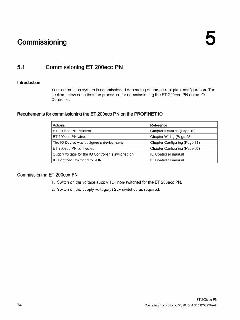
ET 200eco PN 74 Operating Instructions, 01/2015, A5E01250250-AH
Commissioning 5 5.1 Commissioning ET 200eco PN
Introduction Your automation system is commissioned depending on the current plant configuration. The section below describes the procedure for commissioning the ET 200eco PN on an IO Controller.
Requirements for commissioning the ET 200eco PN on the PROFINET IO Actions Reference ET 200eco PN installed Chapter Installing (Page 19) ET 200eco PN wired Chapter Wiring (Page 28) The IO Device was assigned a device name Chapter Configuring (Page 65) ET 200eco PN configured Chapter Configuring (Page 65) Supply voltage for the IO Controller is switched on IO Controller manual IO Controller switched to RUN IO Controller manual
Commissioning ET 200eco PN 1. Switch on the voltage supply 1L+ non-switched for the ET 200eco PN.
2. Switch on the supply voltage(s) 2L+ switched as required.
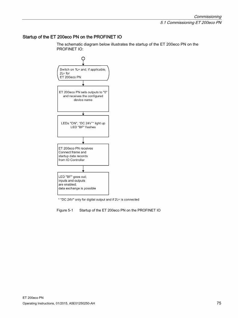
Commissioning 5.1 Commissioning ET 200eco PN
ET 200eco PN Operating Instructions, 01/2015, A5E01250250-AH 75
Startup of the ET 200eco PN on the PROFINET IO The schematic diagram below illustrates the startup of the ET 200eco PN on the PROFINET IO:
Figure 5-1 Startup of the ET 200eco PN on the PROFINET IO

ET 200eco PN 76 Operating Instructions, 01/2015, A5E01250250-AH
Maintenance 6 6.1 Replacing the fuse
Introduction The terminal block is equipped with replaceable fuses.
The figure below shows the fuses in the terminal block.
Figure 6-1 Fuses in the terminal block
Requirements Switch off the supply voltage before you replace any fuses. Result: CPU stop of the ET 200eco PN.
Replacing a fuse of the terminal block 1. Remove the screws from the front panel of the terminal block using a crosstip
screwdriver.
2. Remove the top section.
3. Remove the faulty fuse.
4. Press the new fuse (miniature copper flat fuse, type FK1, 7.5 A, fast-blow) into the fuse holder. The fuse is available as accessory.
5. Connect the terminal block and tighten the screws.
6. Switch on the supply voltage again.
Maintenance 6.2 Online firmware update by means of STEP 7 Manager
ET 200eco PN Operating Instructions, 01/2015, A5E01250250-AH 77
6.2 Online firmware update by means of STEP 7 Manager
Introduction To update the firmware of the ET 200eco PN including its I/O devices, you require the *.UPD files containing the current firmware version.
Requirements An online firmware update can be performed as of STEP 7 V5.4 + SP2.
The I/O device of the station whose firmware is to be updated must be accessible online. The network card used must be set to "TCP/IP (Auto)" in the SIMATIC Manager under Options > Set PG/PC Interface.
The files containing the current firmware versions must be available in the file system of your programming device or PC. A folder must contain the files of one firmware version only.
NOTICE
The I/O device must be reset to the factory setting before the firmware update is carried out when special port parameter assignments have been carried out.
Maintenance 6.2 Online firmware update by means of STEP 7 Manager
ET 200eco PN 78 Operating Instructions, 01/2015, A5E01250250-AH
Performing a firmware update 1. Start STEP 7.
2. In the SIMATIC Manager select PLC > Available stations.
3. Select the I/O device.
4. Select the menu command PLC > Update Firmware. I/O devices without NameOfStation (NoS) are displayed with their MAC address.
As of STEP 7 V5.4 SP5, Slot 0 must also be specified for the I/O devices. In previous versions of STEP 7 this setting is specified implicitly.
When setting the ET 200eco PN IO-Link Master, you can carry out updating of functional units:
– Slot 0: ProfiNet functional unit
– Slot 1: IO-Link functional unit
– Slot 2: 8 DI + 4 DQ functional unit
5. In the Update Firmware dialog, select the path to the firmware update files (*.UPD) using the "Browse" button.
6. After you have selected a file, the information in the bottom boxes of the "Update Firmware" dialog box indicates the I/O device for which the file is suitable and from which firmware version. If the firmware is to be loaded immediately after successful installation, select the check box "Activate firmware after download". If the check box is not selected, the firmware becomes active after the next Power Off/On.
7. Click "Run". The I/O device then automatically updates the firmware.
Result You have updated your ET 200eco PN device online with a new firmware version.
Starting with version V6.0.0, if the ET 200eco PN I/O device was reset to the factory settings before the firmware update, the port parameter assignments are transmitted and activated again as a result of the neighborhood detection after the first connection is established between the controller and the ET 200eco PN I/O device. In previous versions, the device name had to be reassigned by selecting PLC > Edit Ethernet Nodes ... .
Note
You can also update the firmware using HW Config. You can find additional information in the STEP 7 online help.
Maintenance 6.3 Acyclic data exchange with the FB IOL_CALL
ET 200eco PN Operating Instructions, 01/2015, A5E01250250-AH 79
6.3 Acyclic data exchange with the FB IOL_CALL
Function block "IOL_CALL" The function block IOL_CALL is available as a download for controllers of the S7-400 and S7-300 families for acyclic data exchange.
The function block supports you in the following tasks:
Parameterization of an IO-Link Device during operation
Executing IO-Link port functions
Backing up/restoring IO-Link Device parameters
Backing up/restoring IO-Link Master parameters
Procedure for configuring an IO-Link Master with S7-PCT 1. Copy the IO-Link CALL function block FB1 (including data block DB10) to a STEP 7
project.
2. Use the IO-Link CALL function block FB1 as described in the demo project.
Reference You can download the "IOL_CALL" function block and its description from the Internet (http://support.automation.siemens.com/WW/view/en/33102519/133100).
6.4 Exchange object
Exchange object With HW Config, the I/O devices are exchanged, for example, an 8-channel I/O device is replaced by a 16-channel I/O device. The following takes place:
With the "Exchange object" function, the device name, IP-address, etc. are taken over. The module/channel parameters are set to the "default" values.

ET 200eco PN 80 Operating Instructions, 01/2015, A5E01250250-AH
Interrupt, error, and system messages 7 7.1 Interrupts of ET 200eco PN
Introduction The IO Device generates interrupts as a reaction to specific error events. Interrupts are evaluated depending on the IO Controller used.
Evaluating interrupts using an IO Controller The ET 200eco PN supports the following interrupts:
Diagnostics interrupts
Maintenance interrupts
In the event of an interrupt, interrupt OBs are executed automatically in the CPU of the IO Controller (refer to the System Software for S7-300/400 System and Standard Functions (http://support.automation.siemens.com/WW/view/en/1214574) Manual, chapter "Program design").
Information on the cause and class of the error is already available based on the OB number and start information.
You can obtain detailed information on the error event in the error OB by calling SFB 54 RALRM (read supplementary interrupt information).
Triggering diagnostics interrupts After having detected an incoming or outgoing event (e.g., wire break), the device triggers a diagnostic interrupt for "Group diagnostics", if enabled, and for "Diagnostics for the relevant channel".
The CPU interrupts the processing of the user program and processes the diagnostics block OB 82. The event which led to the triggering of the interrupt is entered in the start information of OB 82.

Interrupt, error, and system messages 7.2 Maintenance interrupts
ET 200eco PN Operating Instructions, 01/2015, A5E01250250-AH 81
7.2 Maintenance interrupts
Introduction The PROFINET interfaces of the ET 200eco PN support the diagnostics concept and maintenance concept in PROFINET as defined in IEC 61158-6-10. The objective is early detection and elimination of potential disturbances.
Maintenance interrupts The following maintenance interrupts are available for the ET 200eco PN:
Sync mismatch (no synchronization)
Jitter out of Boundary (jitter too high)
Frame dropped (frames are discarded)
System alarms in STEP 7 The maintenance information is generated in STEP 7 with the following system alarms:
Maintenance required, identified by a yellow wrench icon at the relevant port.
See also For further information, see the SIMATIC PROFINET system description (http://support.automation.siemens.com/WW/view/en/19292127) System Manual and the Migration from PROFIBUS DP to PROFINET IO (http://support.automation.siemens.com/WW/view/en/19289930) Programming Manual.

Interrupt, error, and system messages 7.3 Diagnostics by means of LED display
ET 200eco PN 82 Operating Instructions, 01/2015, A5E01250250-AH
7.3 Diagnostics by means of LED display
7.3.1 Diagnostics using the LED display on the I/O devices
LED display The figure below shows the position and arrangement of the LED display on the ET 200eco PN I/O devices:
① SF/MT: (red/yellow LED) ② BF: Bus monitoring (red LED) ③ ON: Electronic/sensor/load supply 1L+ non-switched (green LED) ④ DC 24V: Load voltage supply 2L+ switched (green LED), only for digital output device ⑤ P1 LK: Port1 Link (green LED) ⑥ P2 LK: Port2 Link (green LED) ⑦ Channel status, channel fault (green/red LED)
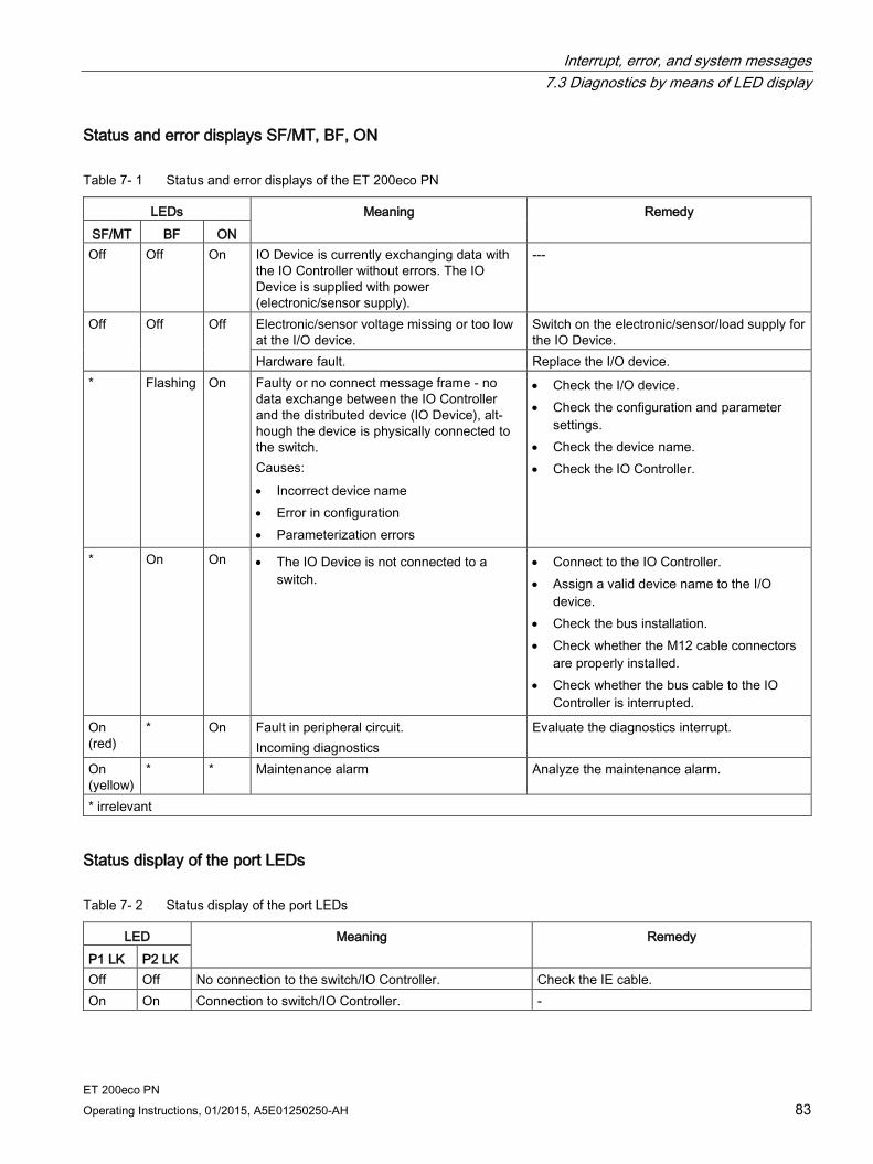
Interrupt, error, and system messages 7.3 Diagnostics by means of LED display
ET 200eco PN Operating Instructions, 01/2015, A5E01250250-AH 83
Status and error displays SF/MT, BF, ON
Table 7- 1 Status and error displays of the ET 200eco PN
LEDs Meaning Remedy SF/MT BF ON
Off Off On IO Device is currently exchanging data with the IO Controller without errors. The IO Device is supplied with power (electronic/sensor supply).
---
Off Off Off Electronic/sensor voltage missing or too low at the I/O device.
Switch on the electronic/sensor/load supply for the IO Device.
Hardware fault. Replace the I/O device. * Flashing On Faulty or no connect message frame - no
data exchange between the IO Controller and the distributed device (IO Device), alt-hough the device is physically connected to the switch. Causes: • Incorrect device name • Error in configuration • Parameterization errors
• Check the I/O device. • Check the configuration and parameter
settings. • Check the device name. • Check the IO Controller.
* On On • The IO Device is not connected to a switch.
• Connect to the IO Controller. • Assign a valid device name to the I/O
device. • Check the bus installation. • Check whether the M12 cable connectors
are properly installed. • Check whether the bus cable to the IO
Controller is interrupted.
On (red)
* On Fault in peripheral circuit. Incoming diagnostics
Evaluate the diagnostics interrupt.
On (yellow)
* * Maintenance alarm Analyze the maintenance alarm.
* irrelevant
Status display of the port LEDs
Table 7- 2 Status display of the port LEDs
LED Meaning Remedy P1 LK P2 LK Off Off No connection to the switch/IO Controller. Check the IE cable. On On Connection to switch/IO Controller. -
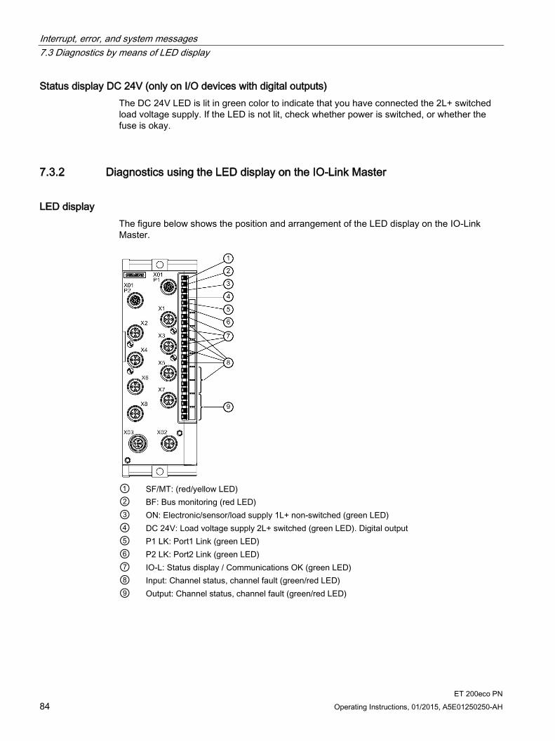
Interrupt, error, and system messages 7.3 Diagnostics by means of LED display
ET 200eco PN 84 Operating Instructions, 01/2015, A5E01250250-AH
Status display DC 24V (only on I/O devices with digital outputs) The DC 24V LED is lit in green color to indicate that you have connected the 2L+ switched load voltage supply. If the LED is not lit, check whether power is switched, or whether the fuse is okay.
7.3.2 Diagnostics using the LED display on the IO-Link Master
LED display The figure below shows the position and arrangement of the LED display on the IO-Link Master.
① SF/MT: (red/yellow LED) ② BF: Bus monitoring (red LED) ③ ON: Electronic/sensor/load supply 1L+ non-switched (green LED) ④ DC 24V: Load voltage supply 2L+ switched (green LED). Digital output ⑤ P1 LK: Port1 Link (green LED) ⑥ P2 LK: Port2 Link (green LED) ⑦ IO-L: Status display / Communications OK (green LED) ⑧ Input: Channel status, channel fault (green/red LED) ⑨ Output: Channel status, channel fault (green/red LED)

Interrupt, error, and system messages 7.3 Diagnostics by means of LED display
ET 200eco PN Operating Instructions, 01/2015, A5E01250250-AH 85
Status display of the IO-L LEDs
Table 7- 3 Status display of the IO-L LEDs
LED Meaning IO-L On In DI/DQ operating mode:
• Status when input or output is activated
On In IO-Link operating mode: • When communication is running
Flashes at 2 Hz • During starting or continuously if a functional IO-Link Device was not found
Reference For status and error displays see Section Diagnostics using the LED display on the I/O devices (Page 82)

Interrupt, error, and system messages 7.3 Diagnostics by means of LED display
ET 200eco PN 86 Operating Instructions, 01/2015, A5E01250250-AH
7.3.3 Diagnostics using the LED display at the voltage distributor
LED display The figure below shows the position and arrangement of the LED display on the voltage distributor.
① Loop-through 1L/2L (green LED) ② Infeed voltage (green LED)
Figure 7-1 LED display at voltage distributor
Table 7- 4 Status displays on the voltage distributor
LED Meaning 1L/2L Loop-through On Voltage applied Flashing Overload Off Short-circuit Infeed voltage On Voltage applied Off Voltage not applied
Interrupt, error, and system messages 7.4 Diagnostics messages of the I/O devices
ET 200eco PN Operating Instructions, 01/2015, A5E01250250-AH 87
7.4 Diagnostics messages of the I/O devices
Actions after a diagnostics message Every diagnostics message triggers the following actions:
The SF LED (red) of the I/O device lights up.
Several simultaneous diagnostics messages are possible.
Diagnostics data are reported as diagnostics interrupts and can be read from data records.
Diagnostics messages are saved to the diagnostics buffer of the I/O controller.
OB 82 is called. If there is no OB 82, the IO Controller goes to STOP.
Acknowledgment of the diagnostics interrupt to enable new interrupts.
7.5 Diagnostics with STEP 7
7.5.1 Reading diagnostics data
Options for reading the diagnostics data
Table 7- 5 Reading diagnostics data in STEP 7
Automation system with IO Controller
Block or register in STEP 7
Application See ...
SIMATIC S7 For example in HW Config by selecting Station > Open Online
Device diagnostics in plain text on the STEP 7 interface (in the Quick View, Diagnostics View or Module Status windows)
"Hardware diagnostics" in the STEP 7 online help
SFB 52 "RDREC"
Reading data records from the IO Device
SFB, see STEP 7 online help (System functions/System function blocks)
SFB 54 "RALRM"
Receiving interrupts from the IO Device
SFB, see STEP 7 online help (System functions/System function blocks)

Interrupt, error, and system messages 7.5 Diagnostics with STEP 7
ET 200eco PN 88 Operating Instructions, 01/2015, A5E01250250-AH
7.5.2 Channel diagnostics
Additional information regarding the data records for PROFINET IO For information on the structure of diagnostics data records, including programming examples, refer to the Migration from PROFIBUS DP to PROFINET IO (http://support.automation.siemens.com/WW/view/en/19289930) Programming Manual.
Structure of the manufacturer-specific diagnostics data records The structure of the diagnostics data records is differentiated based on the BlockVersion. The following block versions apply to the ET 200eco PN: ET 200eco PN Order number BlockVersion 8 DI DC 24V 4×M12 6ES7141-6BF00-0AB0 W#16#0101 8 DI DC 24V 8×M12 6ES7141-6BG00-0AB0 W#16#0101 16 DI DC 24V 8×M12 6ES7141-6BH00-0AB0 W#16#0101 8 DO DC 24V/1,3A 4×M12 6ES7142-6BF00-0AB0 W#16#0101 8 DO DC 24V/0,5A 4×M12 6ES7142-6BF50-0AB0 W#16#0101 8 DO DC 24V/1,3A 8×M12 6ES7142-6BG00-0AB0 W#16#0101 8 DO DC 24V/2,0A 8×M12 6ES7142-6BR00-0AB0 W#16#0101 16 DO DC 24V/1,3A 8×M12 6ES7142-6BH00-0AB0 W#16#0101 8 DIO DC 24V/1,3A 8×M12 6ES7147-6BG00-0AB0 W#16#0101 4 IO-L + 8 DI + 4 DO DC 24V/1,3A 8×M12 6ES7148-6JA00-0AB0 W#16#0101 8 AI 4 U/I + 4 RTD/TC 8×M12 6ES7144-6KD00-0AB0 W#16#0101 8 AI RTD/TC 8×M12 6ES7144-6KD50-0AB0 W#16#0101 4 AO U/I 4×M12 6ES7145-6HD00-0AB0 W#16#0101
Manufacturer-specific diagnostics in the User Structure Identifier (USI) W#16#8000 channel diagnostics
W#16#8002 advanced channel diagnostics (maintenance alarms)

Interrupt, error, and system messages 7.5 Diagnostics with STEP 7
ET 200eco PN Operating Instructions, 01/2015, A5E01250250-AH 89
7.5.3 Error classes for I/O devices
Error classes and remedies The table below lists the error classes for the I/O devices.
Table 7- 6 Error classes for the IO devices digital inputs, digital outputs, analog inputs, analog outputs
Error class Error text Meaning Remedy 00001B 1D Short-circuit • Short-circuit to M at the sensor supply
line • Short-circuit at the output line • Load impedance too low
• Correct the process wiring • Check the sensor or actuator
00100B 4D Thermal overload
• I/O device is overheating • Check the process wiring • Check the ambient temperature
00110B 6D Wire break • Signal line to a sensor or actuator interrupted
• Sensor or actuator failure • Load impedance too high
• Correct the process wiring • Replace the sensor or actuator • Use a sensor with lower impedance • Use an actuator with lower load imped-
ance
00111B 7D Violation of upper limit
• The value is above the overrange • Correct the I/O device to sensor tuning • Modify measuring range by means of
parameter assignment
01000B 8D Violation of lower limit
• Value is below the underrange • Correct the I/O device to sensor tuning • Modify measuring range by means of
parameter assignment
01001B 9D Error • Internal I/O device error has occurred (diagnostic message on channel 0 applies to the whole I/O device).
• Replacement of I/O device
10000B 16D Parameter assignment errors
• I/O device is incorrectly parameterized • Correct the parameter assignment
10001B 17D 1L+ or 2L+ is missing
• Supply voltages missing or too low • Load voltage supply missing or too low
• Check the supply voltages • Check the load voltage supply • Correct the process wiring
10101B 21D Reference channel fault
• Measurement cable for compensation interrupted
• Data record DS2 incorrect • Timeout with '"Dynamic Ref. Temp."
• Correct the process wiring • Check the data record DS2. • Send DS2

Interrupt, error, and system messages 7.5 Diagnostics with STEP 7
ET 200eco PN 90 Operating Instructions, 01/2015, A5E01250250-AH
Table 7- 7 Error classes for IO-Link Master Slot 1
Error class Error text Meaning IO-Link Master
IO-Link Device
00001B 1D Short-circuit Short-circuit at the process cables of the IO-Link Device (0x5151)
X
00010B 2D Undervoltage Supply voltage too low (0x5110 to 0x5119) X 00100B 4D Overload Overload of the output stage of the IO-Link Devices (0x5410) X 00101B 5D Overtempera-
ture • Ambient temperature too high (0x4110) • IO-Link Device too hot (0x4210) • IO temperature exceeded (0x4310)
X
00110B 6D Wire break • No IO-Link Device connected • Incorrect IO-Link Device connected • Signal cable to IO-Link Device interrupted • Signal cable to IO-Link Device short-circuited • Short-circuit of supply voltage at sensor • IO-Link Device addressed with too short communication cycle
time • IO-Link Device cannot communicate due to another error • (0xFF10)
X
00111B 7D Overflow • Process variable range exceeded (0x8C10) • Measuring range exceeded (0x8C20)
X
01000B 8D Underflow Process variable range too small (0x8C30) X 01001B 9D Error All the IO-Link error codes not listed here will be mapped to this
PROFINET IO error. X
Hardware error at IO-Link Master detected X 10000B 16D Parameter as-
signment errors IO-Link Master could not be parameterized X Event code of the IO-Link Device (0x6230 to 0x6340) X
10010B 18D Fuse defective Event code of the IO-Link Device (0x5450 to 0x5459) X 11010B 26D External error IO-Link Device cannot be set to desired mode X
Note
For IO-Link Devices supplied by Siemens, the manufacturer-specific range 0x8CA0 to 0x8CBF will be mapped to the PROFINET IO error types 0 to 31.
Additional information on your IO-Link Device is available in the operating instructions, for example, for the event codes.
Further information Refer to the STEP 7 online help.
For additional information, see the Migration from PROFIBUS DP to PROFINET IO (http://support.automation.siemens.com/WW/view/en/19289930) Programming Manual.
Interrupt, error, and system messages 7.5 Diagnostics with STEP 7
ET 200eco PN Operating Instructions, 01/2015, A5E01250250-AH 91
7.5.4 STOP of the IO Controller and recovery of the IO Device
Diagnostics events triggered after a STOP of the IO Controller Diagnostics frames received from the IO Device while the IO Controller is in STOP do not trigger the start of corresponding OBs after the restart of the IO Controller. You must explicitly read the diagnostics data from OB 100 to obtain an overview of the device state.
Diagnostics after recovery of the IO Device You must explicitly read data record E00CH by calling SFB 52 after recovery of an IO Device. This record contains all diagnostics data for the device slots assigned to an IO Controller

ET 200eco PN 92 Operating Instructions, 01/2015, A5E01250250-AH
General technical data 8 8.1 Standards and certifications
Introduction The ET 200eco PN distributed I/O system satisfies the requirements and criteria of IEC 61131-2.
Note Information on the nameplate
You will find the currently valid labels and approvals on the type plate of the respective product.
PROFINET IO PROFINET IO is an open transmission protocol with real-time functionality defined in PROFINET.
CE marking Our products fulfill the requirements and safety objectives of the following EC Directives and comply with the harmonized European standards (EN) published for programmable logic controllers in the official journals of the European Communities:
2006/95/EC "Electrical Equipment Designed for Use within Certain Voltage Limits" (LowVoltage Directive)
2004/108/EC "Electromagnetic Compatibility" (EMC Directive)
The EC Declarations of Conformity are kept available for the responsible authorities at:
Siemens Aktiengesellschaft Industry Sector I IA AS FA WF AMB PO Box 1963 D-92209 Amberg, Germany
These files are also available for download on the Customer Support Internet pages, under "Declaration of Conformity".

General technical data 8.1 Standards and certifications
ET 200eco PN Operating Instructions, 01/2015, A5E01250250-AH 93
Marking for Australia and New Zealand Our products are compliant with the requirements of AS/NZS CISPR 16.
cULus approval
Underwriters Laboratories Inc. according to
UL 508 (Industrial Control Equipment)
CSA C22.2 No. 142 (Process Control Equipment)
Note
Class 2 power supply unit
The components must be supplied with a class 2 power supply unit.
Industrial applications SIMATIC products are designed for industrial applications.
Table 8- 1 Industrial applications
Fields of application Requirements for Noise emission Interference immunity
Industry EN 61000-6-4: 2007 EN 61000-6-2:2005
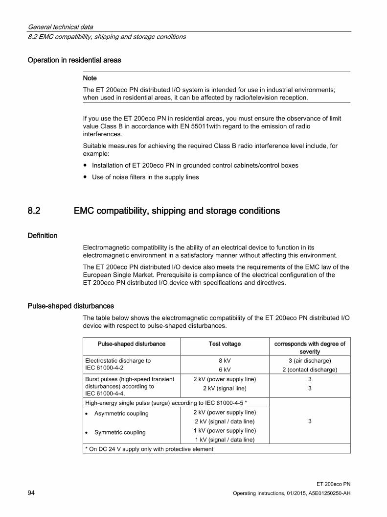
General technical data 8.2 EMC compatibility, shipping and storage conditions
ET 200eco PN 94 Operating Instructions, 01/2015, A5E01250250-AH
Operation in residential areas
Note
The ET 200eco PN distributed I/O system is intended for use in industrial environments; when used in residential areas, it can be affected by radio/television reception.
If you use the ET 200eco PN in residential areas, you must ensure the observance of limit value Class B in accordance with EN 55011with regard to the emission of radio interferences.
Suitable measures for achieving the required Class B radio interference level include, for example:
Installation of ET 200eco PN in grounded control cabinets/control boxes
Use of noise filters in the supply lines
8.2 EMC compatibility, shipping and storage conditions
Definition Electromagnetic compatibility is the ability of an electrical device to function in its electromagnetic environment in a satisfactory manner without affecting this environment.
The ET 200eco PN distributed I/O device also meets the requirements of the EMC law of the European Single Market. Prerequisite is compliance of the electrical configuration of the ET 200eco PN distributed I/O device with specifications and directives.
Pulse-shaped disturbances The table below shows the electromagnetic compatibility of the ET 200eco PN distributed I/O device with respect to pulse-shaped disturbances.
Pulse-shaped disturbance Test voltage corresponds with degree of severity
Electrostatic discharge to IEC 61000-4-2
8 kV 6 kV
3 (air discharge) 2 (contact discharge)
Burst pulses (high-speed transient disturbances) according to IEC 61000-4-4.
2 kV (power supply line) 2 kV (signal line)
3 3
High-energy single pulse (surge) according to IEC 61000-4-5 *
3 • Asymmetric coupling • Symmetric coupling
2 kV (power supply line) 2 kV (signal / data line) 1 kV (power supply line) 1 kV (signal / data line)
* On DC 24 V supply only with protective element
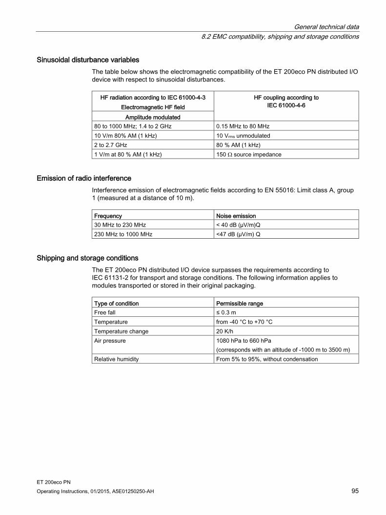
General technical data 8.2 EMC compatibility, shipping and storage conditions
ET 200eco PN Operating Instructions, 01/2015, A5E01250250-AH 95
Sinusoidal disturbance variables The table below shows the electromagnetic compatibility of the ET 200eco PN distributed I/O device with respect to sinusoidal disturbances.
HF radiation according to IEC 61000-4-3 Electromagnetic HF field
HF coupling according to IEC 61000-4-6
Amplitude modulated 80 to 1000 MHz; 1.4 to 2 GHz 0.15 MHz to 80 MHz 10 V/m 80% AM (1 kHz) 10 Vrms unmodulated 2 to 2.7 GHz 80 % AM (1 kHz) 1 V/m at 80 % AM (1 kHz) 150 Ω source impedance
Emission of radio interference Interference emission of electromagnetic fields according to EN 55016: Limit class A, group 1 (measured at a distance of 10 m). Frequency Noise emission 30 MHz to 230 MHz < 40 dB (µV/m)Q 230 MHz to 1000 MHz <47 dB (µV/m) Q
Shipping and storage conditions The ET 200eco PN distributed I/O device surpasses the requirements according to IEC 61131-2 for transport and storage conditions. The following information applies to modules transported or stored in their original packaging. Type of condition Permissible range Free fall ≤ 0.3 m Temperature from -40 °C to +70 °C Temperature change 20 K/h Air pressure 1080 hPa to 660 hPa
(corresponds with an altitude of -1000 m to 3500 m) Relative humidity From 5% to 95%, without condensation
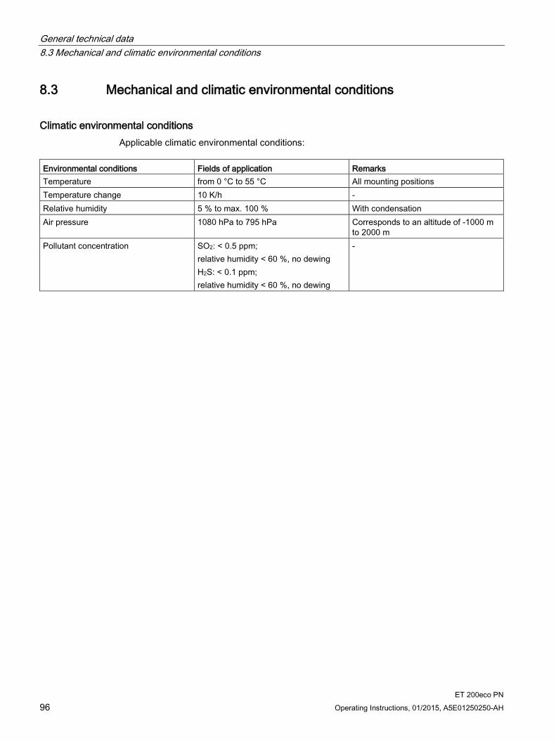
General technical data 8.3 Mechanical and climatic environmental conditions
ET 200eco PN 96 Operating Instructions, 01/2015, A5E01250250-AH
8.3 Mechanical and climatic environmental conditions
Climatic environmental conditions Applicable climatic environmental conditions:
Environmental conditions Fields of application Remarks Temperature from 0 °C to 55 °C All mounting positions Temperature change 10 K/h - Relative humidity 5 % to max. 100 % With condensation Air pressure 1080 hPa to 795 hPa Corresponds to an altitude of -1000 m
to 2000 m Pollutant concentration SO2: < 0.5 ppm;
relative humidity < 60 %, no dewing H2S: < 0.1 ppm; relative humidity < 60 %, no dewing
-

General technical data 8.3 Mechanical and climatic environmental conditions
ET 200eco PN Operating Instructions, 01/2015, A5E01250250-AH 97
Operating temperature range for the devices The following devices can be used in different temperature ranges (indoor use only):
Designation Order number Fields of application From
product version
-25 °C to 55 °C
-25 °C to 60 °C
-40 °C to 60 °C
Terminal block 6ES7194-6CA00-0AA0 X 1 PD DC 24V 1×7/8" 4×M12 6ES7148-6CB00-0AA0 X 1 8 DI DC 24V 4×M12 6ES7141-6BF00-0AB0 X X 1
X X X 4 8 DI DC 24V 8×M12 6ES7141-6BG00-0AB0 X X 1
X X X 4 16 DI DC 24V 8×M12 6ES7141-6BH00-0AB0 X X 1
X X X 4 8 DO DC 24V/1,3A 4×M12 6ES7142-6BF00-0AB0 X X 1
X X X 4 8 DO DC 24V/0,5A 4×M12 6ES7142-6BF50-0AB0 X X 1
X X X 4 8 DO DC 24V/1,3A 8×M12 6ES7142-6BG00-0AB0 X X 1
X X X 4 8 DO DC 24V/2,0A 8×M12 6ES7142-6BR00-0AB0 X X 1
X X X 4 16 DO DC 24V/1,3A 8×M12 6ES7142-6BH00-0AB0 X X 1
X X X 4 8 DIO DC 24 V/1,3A 8×M12 6ES7147-6BG00-0AB0 X X 1
X X X 4 4 IO-L + 8 DI + 4 DO DC 24V/1,3A 8×M12 6ES7148-6JA00-0AB0 X X 1 8 AI 4 U/I + 4 RTD/TC 8×M12 6ES7144-6KD00-0AB0 X X 1
X X X 4 8 AI RTD/TC 8×M12 6ES7144-6KD50-0AB0 X X X 1 4 AO U/I 4×M12 6ES7145-6HD00-0AB0 X X 1
X X X 4 Mounting rail 6ES7194-6GA00-0AA0 X X X 1
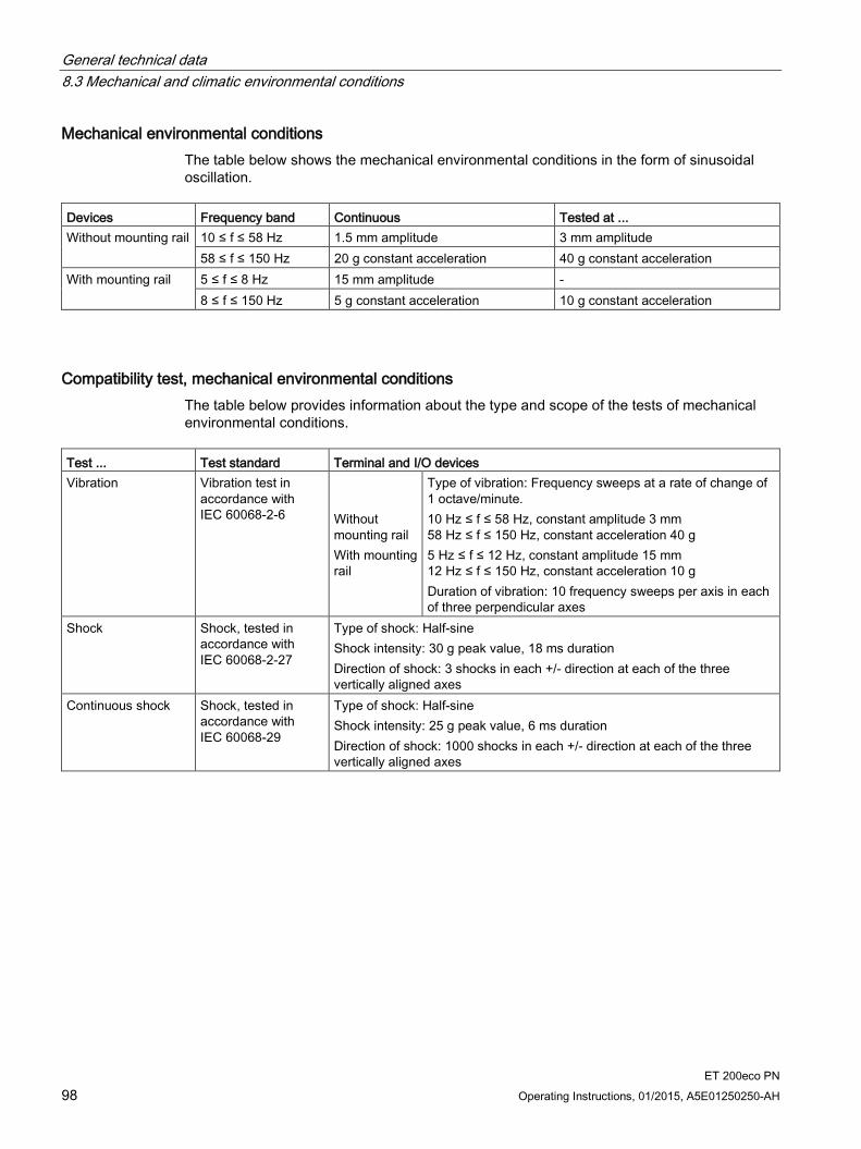
General technical data 8.3 Mechanical and climatic environmental conditions
ET 200eco PN 98 Operating Instructions, 01/2015, A5E01250250-AH
Mechanical environmental conditions The table below shows the mechanical environmental conditions in the form of sinusoidal oscillation.
Devices Frequency band Continuous Tested at ... Without mounting rail 10 ≤ f ≤ 58 Hz 1.5 mm amplitude 3 mm amplitude
58 ≤ f ≤ 150 Hz 20 g constant acceleration 40 g constant acceleration With mounting rail 5 ≤ f ≤ 8 Hz 15 mm amplitude -
8 ≤ f ≤ 150 Hz 5 g constant acceleration 10 g constant acceleration
Compatibility test, mechanical environmental conditions The table below provides information about the type and scope of the tests of mechanical environmental conditions.
Test ... Test standard Terminal and I/O devices Vibration Vibration test in
accordance with IEC 60068-2-6
Without mounting rail With mounting rail
Type of vibration: Frequency sweeps at a rate of change of 1 octave/minute. 10 Hz ≤ f ≤ 58 Hz, constant amplitude 3 mm 58 Hz ≤ f ≤ 150 Hz, constant acceleration 40 g 5 Hz ≤ f ≤ 12 Hz, constant amplitude 15 mm 12 Hz ≤ f ≤ 150 Hz, constant acceleration 10 g Duration of vibration: 10 frequency sweeps per axis in each of three perpendicular axes
Shock Shock, tested in accordance with IEC 60068-2-27
Type of shock: Half-sine Shock intensity: 30 g peak value, 18 ms duration Direction of shock: 3 shocks in each +/- direction at each of the three vertically aligned axes
Continuous shock Shock, tested in accordance with IEC 60068-29
Type of shock: Half-sine Shock intensity: 25 g peak value, 6 ms duration Direction of shock: 1000 shocks in each +/- direction at each of the three vertically aligned axes

General technical data 8.3 Mechanical and climatic environmental conditions
ET 200eco PN Operating Instructions, 01/2015, A5E01250250-AH 99
Extended environmental conditions for outdoor use The table below provides information about the type and scope of the tests for extended environmental conditions for outdoor use.
Test ... Test standard Conditions/Comments Salt spray IEC 60068-2-52 Severity level 1 for products used at sea or close to the ocean:
4 cycles each with: • 2 h with 5 % NaCl at 35 °C • 7 days at 40 °C/93 % rel. humidity
UV resistance Chamber with glass: Sun test CPS plus Fa. Atlas Duration: 12 weeks • Irradiance (E): 550 W/m² • Black standard temperature (BST): 55 °C
Condensation changing climate
DIN EN ISO 6270-2 Condensation climate with alternating humidity and air temperature (AHT): 84 cycles each with: • 8 h at 40 °C +3 °C with 100% relative humidity (condensation) • 16 h at 18 °C to 28 °C with 100% relative humidity
Thermal shock test IEC 60068-2-14 Na Temperature: -40 °C/+125 °C Duration: 500 cycles (500 h) Device is switched off
Hot storage IEC 60068-2-2 Bb Temperature: 100 °C Duration: 1 year
Devices for operating range of extended environmental conditions in outdoor use The following devices can be used for extended environmental conditions in outdoor use:
Designation Order number From product version 8 DI DC 24V 4×M12 6ES7141-6BF00-0AB0 4 8 DI DC 24V 8×M12 6ES7141-6BG00-0AB0 4 16 DI DC 24V 8×M12 6ES7141-6BH00-0AB0 4 8 DO DC 24V/1,3A 4×M12 6ES7142-6BF00-0AB0 4 8 DO DC 24V/0,5A 4×M12 6ES7142-6BF50-0AB0 4 8 DO DC 24V/1,3A 8×M12 6ES7142-6BG00-0AB0 4 8 DO DC 24V/2,0A 8×M12 6ES7142-6BR00-0AB0 4 16 DO DC 24V/1,3A 8×M12 6ES7142-6BH00-0AB0 4 8 DIO DC 24 V/1,3A 8×M12 6ES7147-6BG00-0AB0 4 8 AI 4 U/I + 4 RTD/TC 8×M12 6ES7144-6KD00-0AB0 4 8 AI RTD/TC 8×M12 6ES5144-6KD50-0AB0 1 4 AO U/I 4×M12 6ES7145-6HD00-0AB0 4

General technical data 8.4 Specification of dielectric tests, protection class, degree of protection, and rated voltage of ET 200eco PN
ET 200eco PN 100 Operating Instructions, 01/2015, A5E01250250-AH
8.4 Specification of dielectric tests, protection class, degree of protection, and rated voltage of ET 200eco PN
Test voltage The insulation stability is tested with the following test voltage according to IEC 61131-2 during type testing: Circuits with Rated voltage Vinagainst other circuits or ground Test voltage
< 50 V DC 500 V < 150 V 2500 V DC < 250 V 4000 V DC
Degree of pollution/overvoltage category according to IEC 61131 Pollution degree 1
Pollution degree 2 for terminal block and the voltage distributor.
Overvoltage category
– at Urated = DC 24 V: II
Degree of protection IP 65 Degree of protection according to IEC 60529:
Protection against the ingress of dust and full touch protection
Water projected by a nozzle against the enclosure from any direction shall have no harmful effect.
Degree of protection IP66 and IP67 Degree of protection according to IEC 60529:
Protection against the ingress of dust and full touch protection
IP66: Protection against water from heavy seas or water projected in powerful jets (water must not enter the enclosure in harmful quantities)
IP67: Protection against water when enclosure is immersed at specified pressures over a specified time period (water must not enter the enclosure in harmful quantities)
Rated voltage for operation The ET 200eco PN distributed I/O device operates with the following rated voltage and corresponding tolerances. Rated voltage Tolerance range DC 24 V 20.4 to 28.8 V DC
ET 200eco PN Operating Instructions, 01/2015, A5E01250250-AH 101
I/O device digital inputs/digital outputs 9 9.1 I/O device digital inputs
9.1.1 I/O device 8 DI DC 24 V 4xM12
Order number 6ES7141-6BF00-0AB0
Properties The 8 DI DC 24V 4×M12 I/O device has the following properties:
8 digital inputs
Dimensions 30 x 200 mm, dual assignment of the sockets
Rated input voltage DC 24 V
Suitable for switches and proximity switches
Diagnostics
– "Missing 1L+" for the I/O device
– "Short-circuit to M at sensor supply", per channel group
– "Wire break", per channel
Prioritized startup
Media redundancy
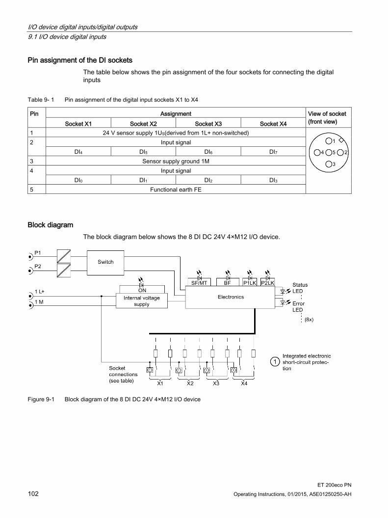
I/O device digital inputs/digital outputs 9.1 I/O device digital inputs
ET 200eco PN 102 Operating Instructions, 01/2015, A5E01250250-AH
Pin assignment of the DI sockets The table below shows the pin assignment of the four sockets for connecting the digital inputs
Table 9- 1 Pin assignment of the digital input sockets X1 to X4
Pin Assignment View of socket (front view) Socket X1 Socket X2 Socket X3 Socket X4
1 24 V sensor supply 1US(derived from 1L+ non-switched)
2 Input signal DI4 DI5 DI6 DI7
3 Sensor supply ground 1M 4 Input signal
DI0 DI1 DI2 DI3 5 Functional earth FE
Block diagram The block diagram below shows the 8 DI DC 24V 4×M12 I/O device.
Figure 9-1 Block diagram of the 8 DI DC 24V 4×M12 I/O device
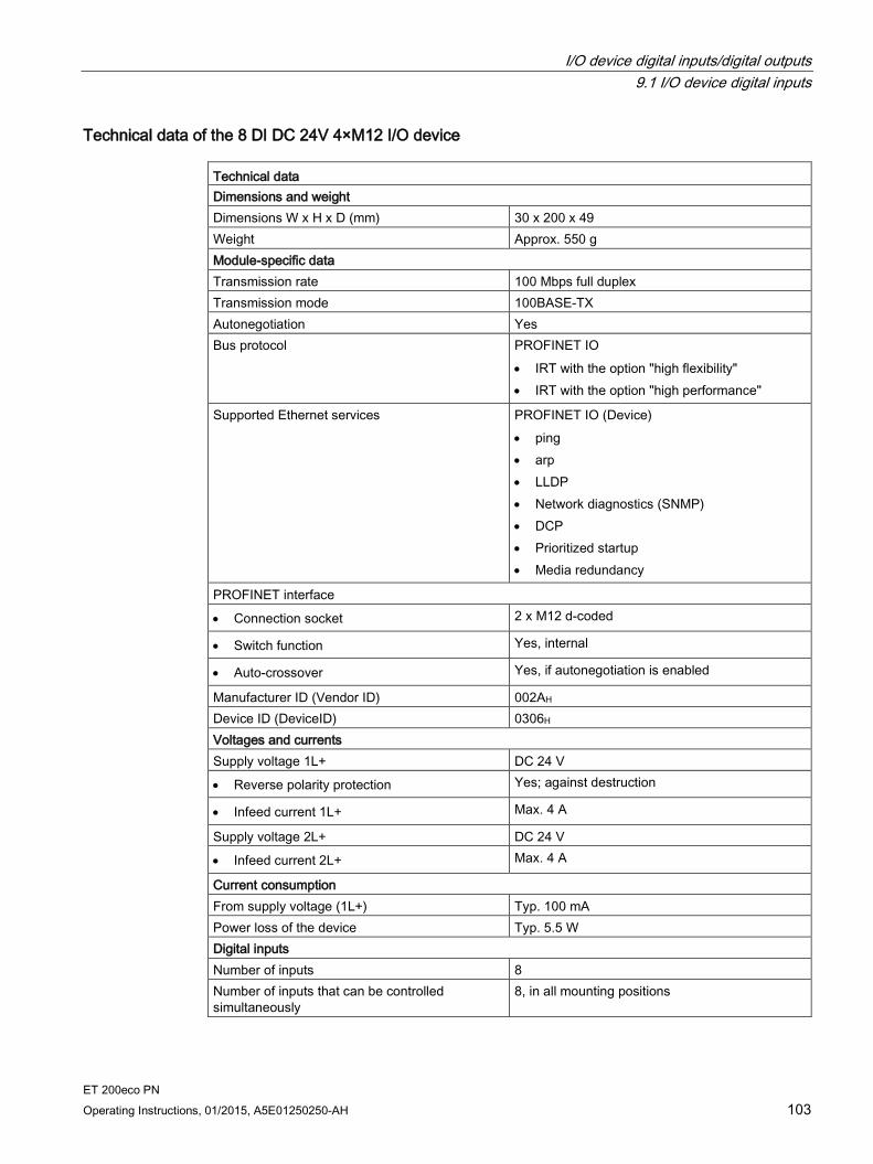
I/O device digital inputs/digital outputs 9.1 I/O device digital inputs
ET 200eco PN Operating Instructions, 01/2015, A5E01250250-AH 103
Technical data of the 8 DI DC 24V 4×M12 I/O device Technical data Dimensions and weight Dimensions W x H x D (mm) 30 x 200 x 49 Weight Approx. 550 g Module-specific data Transmission rate 100 Mbps full duplex Transmission mode 100BASE-TX Autonegotiation Yes Bus protocol PROFINET IO
• IRT with the option "high flexibility" • IRT with the option "high performance"
Supported Ethernet services PROFINET IO (Device) • ping • arp • LLDP • Network diagnostics (SNMP) • DCP • Prioritized startup • Media redundancy
PROFINET interface
• Connection socket 2 x M12 d-coded
• Switch function Yes, internal
• Auto-crossover Yes, if autonegotiation is enabled
Manufacturer ID (Vendor ID) 002AH Device ID (DeviceID) 0306H Voltages and currents Supply voltage 1L+ DC 24 V
• Reverse polarity protection Yes; against destruction
• Infeed current 1L+ Max. 4 A
Supply voltage 2L+ DC 24 V
• Infeed current 2L+ Max. 4 A
Current consumption From supply voltage (1L+) Typ. 100 mA Power loss of the device Typ. 5.5 W Digital inputs Number of inputs 8 Number of inputs that can be controlled simultaneously
8, in all mounting positions
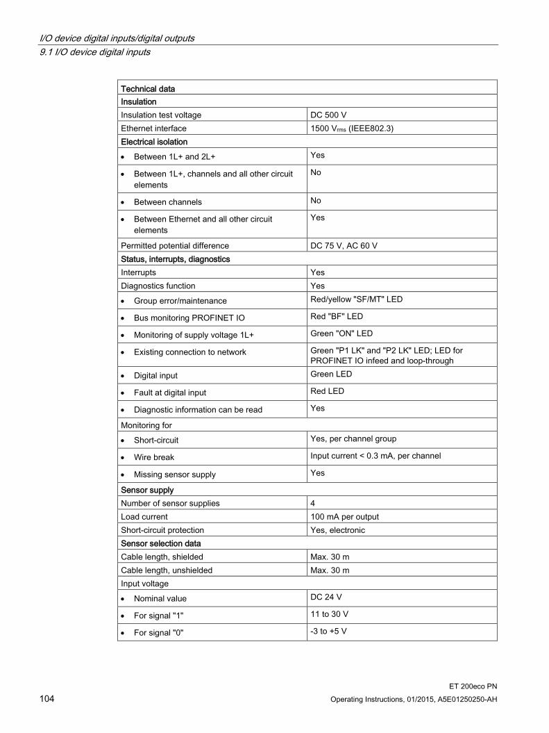
I/O device digital inputs/digital outputs 9.1 I/O device digital inputs
ET 200eco PN 104 Operating Instructions, 01/2015, A5E01250250-AH
Technical data Insulation Insulation test voltage DC 500 V Ethernet interface 1500 Vrms (IEEE802.3) Electrical isolation
• Between 1L+ and 2L+ Yes
• Between 1L+, channels and all other circuit elements
No
• Between channels No
• Between Ethernet and all other circuit elements
Yes
Permitted potential difference DC 75 V, AC 60 V Status, interrupts, diagnostics Interrupts Yes Diagnostics function Yes
• Group error/maintenance Red/yellow "SF/MT" LED
• Bus monitoring PROFINET IO Red "BF" LED
• Monitoring of supply voltage 1L+ Green "ON" LED
• Existing connection to network Green "P1 LK" and "P2 LK" LED; LED for PROFINET IO infeed and loop-through
• Digital input Green LED
• Fault at digital input Red LED
• Diagnostic information can be read Yes
Monitoring for
• Short-circuit Yes, per channel group
• Wire break Input current < 0.3 mA, per channel
• Missing sensor supply Yes
Sensor supply Number of sensor supplies 4 Load current 100 mA per output Short-circuit protection Yes, electronic Sensor selection data Cable length, shielded Max. 30 m Cable length, unshielded Max. 30 m Input voltage
• Nominal value DC 24 V
• For signal "1" 11 to 30 V
• For signal "0" -3 to +5 V

I/O device digital inputs/digital outputs 9.1 I/O device digital inputs
ET 200eco PN Operating Instructions, 01/2015, A5E01250250-AH 105
Technical data Input current
• For signal "1" Typ. 7 mA
Input delay
• At "0" to "1" Typ. 3 ms
• At "1" to "0" Typ. 3 ms
Input characteristic According to IEC 61131, Type 3 Connection of 2-wire proximity switches Possible
• Permitted quiescent current Max. 1.5 mA
9.1.2 I/O device 8 DI DC 24 V 8xM12
Order number 6ES7141-6BG00-0AB0
Properties The 8 DI DC 24V 8×M12 I/O device has the following properties:
8 digital inputs
Dimensions 60 x 175 mm, single assignment of the sockets
Rated input voltage DC 24 V
Suitable for switches and proximity switches
Diagnostics
– "Missing 1L+" for the I/O device
– "Short-circuit to M at sensor supply" per channel
– "Wire break", per channel
Prioritized startup
Media redundancy

I/O device digital inputs/digital outputs 9.1 I/O device digital inputs
ET 200eco PN 106 Operating Instructions, 01/2015, A5E01250250-AH
Pin assignment of the sockets The table below shows the pin assignment of the eight sockets for connecting the digital inputs.
Table 9- 2 Pin assignment of sockets X1 to X8 for digital inputs
Pin Assignment View of socket (front view) Socket X1 Socket X2 Socket X3 Socket X4 Socket X5 Socket X6 Socket X7 Socket X8
1 24 V sensor supply 1US(derived from 1L+ non-switched)
2 Not used 3 Sensor supply ground 1M 4 Input signal
DI0 DI1 DI2 DI3 DI4 DI5 DI6 DI7 5 Functional earth FE
Block diagram The block diagram below shows the 8 DI DC 24V 8×M12 I/O device.
Figure 9-2 Block diagram of the 8 DI DC 24V 8×M12 I/O device

I/O device digital inputs/digital outputs 9.1 I/O device digital inputs
ET 200eco PN Operating Instructions, 01/2015, A5E01250250-AH 107
Technical data of the 8 DI DC 24V 8×M12 I/O device Technical data Dimensions and weight Dimensions W x H x D (mm) 60 x 175 x 49 Weight Approx. 910 g Module-specific data Transmission rate 100 Mbps full duplex Transmission mode 100BASE-TX Autonegotiation Yes Bus protocol PROFINET IO
• IRT with the option "high flexibility" • IRT with the option "high performance"
Supported Ethernet services PROFINET IO (Device) • ping • arp • LLDP • Network diagnostics (SNMP) • DCP • Prioritized startup • Media redundancy
PROFINET interface
• Connection socket 2 x M12 d-coded
• Switch function Yes, internal
• Auto-crossover Yes, if autonegotiation is enabled
Manufacturer ID (Vendor ID) 002AH Device ID (DeviceID) 0306H Voltages and currents Supply voltage 1L+ DC 24 V
• Reverse polarity protection Yes; against destruction
• Infeed current 1L+ Max. 4 A
Supply voltage 2L+ DC 24 V
• Infeed current 2L+ Max. 4 A
Current consumption From supply voltage (1L+) Typ. 100 mA From supply voltage (2L+) 0 mA Power loss of the device 4.5 W, typical Digital inputs Number of inputs 8 Number of inputs that can be controlled simultaneously
8 in all mounting positions

I/O device digital inputs/digital outputs 9.1 I/O device digital inputs
ET 200eco PN 108 Operating Instructions, 01/2015, A5E01250250-AH
Technical data Insulation Insulation test voltage
• Ethernet interface 1500 Vrms (IEEE802.3)
• all other interfaces DC 500 V
Electrical isolation
• Between 1L+ and 2L+ Yes
• Between 1L+, channels and all other circuit elements
No
• Between channels No
• Between Ethernet and all other circuit elements
Yes
Permitted potential difference
• Between different circuit elements DC 75 V, AC 60 V
Status, interrupts, diagnostics Interrupts Yes Diagnostics function Yes
• Group error/maintenance Red/yellow "SF/MT" LED
• Bus monitoring PROFINET IO Red "BF" LED
• Monitoring of supply voltage 1L+ Green "ON" LED
• Existing connection to network Green "P1 LK" and "P2 LK" LED; LED for PROFINET IO infeed and loop-through
• Digital input Green LED
• Fault at digital input Red LED
• Diagnostic information can be read Yes
Monitoring for
• Short-circuit Yes, per channel
• Wire break Input current < 0.3 mA, per channel
• Missing sensor supply Yes
Sensor supply Number of sensor supplies 8 Load current 100 mA per output Short-circuit protection Yes, electronic Sensor selection data Cable length, shielded Max. 30 m Cable length, unshielded Max. 30 m

I/O device digital inputs/digital outputs 9.1 I/O device digital inputs
ET 200eco PN Operating Instructions, 01/2015, A5E01250250-AH 109
Technical data Input voltage
• Nominal value DC 24 V
• For signal "1" 11 to 30 V
• For signal "0" -3 to +5 V
Input current
• For signal "1" Typ. 7 mA
Input delay
• At "0" to "1" Typ. 3 ms
• At "1" to "0" Typ. 3 ms
Input characteristic According to IEC 61131, Type 3 Connection of 2-wire proximity switches Supported
• Permitted quiescent current Max. 1.5 mA
9.1.3 I/O device 16 DI DC 24 V 8xM12
Order number 6ES7141-6BH00-0AB0
Properties The 16 DI DC 24V 8×M12 I/O device has the following properties:
16 digital inputs
Dimensions 60 x 175 mm, dual assignment of the sockets
Rated input voltage DC 24 V
Suitable for switches and proximity switches
Diagnostics
– "Missing 1L+" for the I/O device
– "Short-circuit to M at sensor supply", per channel group
– "Wire break", per channel
Prioritized startup
Media redundancy
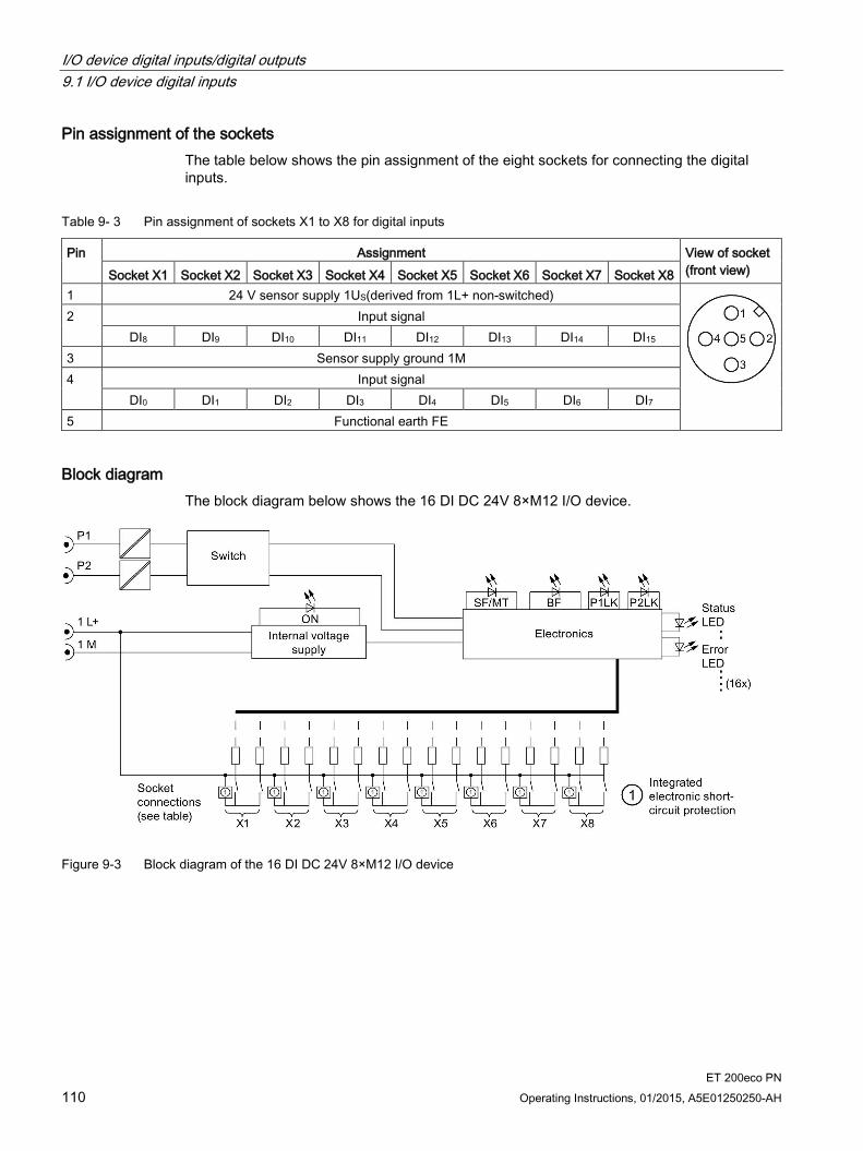
I/O device digital inputs/digital outputs 9.1 I/O device digital inputs
ET 200eco PN 110 Operating Instructions, 01/2015, A5E01250250-AH
Pin assignment of the sockets The table below shows the pin assignment of the eight sockets for connecting the digital inputs.
Table 9- 3 Pin assignment of sockets X1 to X8 for digital inputs
Pin Assignment View of socket (front view) Socket X1 Socket X2 Socket X3 Socket X4 Socket X5 Socket X6 Socket X7 Socket X8
1 24 V sensor supply 1US(derived from 1L+ non-switched)
2 Input signal DI8 DI9 DI10 DI11 DI12 DI13 DI14 DI15
3 Sensor supply ground 1M 4 Input signal
DI0 DI1 DI2 DI3 DI4 DI5 DI6 DI7 5 Functional earth FE
Block diagram The block diagram below shows the 16 DI DC 24V 8×M12 I/O device.
Figure 9-3 Block diagram of the 16 DI DC 24V 8×M12 I/O device

I/O device digital inputs/digital outputs 9.1 I/O device digital inputs
ET 200eco PN Operating Instructions, 01/2015, A5E01250250-AH 111
Technical data of the 16 DI DC 24V 8×M12 I/O device Technical data Dimensions and weight Dimensions W x H x D (mm) 60 x 175 x 49 Weight Approx. 910 g Module-specific data Transmission rate 100 Mbps full duplex Transmission mode 100BASE-TX Autonegotiation Yes Bus protocol PROFINET IO
• IRT with the option "high flexibility" • IRT with the option "high performance"
Supported Ethernet services PROFINET IO (Device) • ping • arp • LLDP • Network diagnostics (SNMP) • DCP • Prioritized startup • Media redundancy
PROFINET interface
• Connection socket 2 x M12 d-coded
• Switch function Yes, internal
• Auto-crossover Yes, if autonegotiation is enabled
Manufacturer ID (Vendor ID) 002AH Device ID (DeviceID) 0306H Voltages and currents Supply voltage 1L+ DC 24 V
• Reverse polarity protection Yes; against destruction
• Infeed current 1L+ Max. 4 A
Supply voltage 2L+ DC 24 V
• Infeed current 2L+ Max. 4 A
Current consumption From supply voltage (1L+) Typ. 100 mA From supply voltage (2L+) 0 mA Power loss of the device 6.5 W, typical Digital inputs Number of inputs 16 Number of inputs that can be controlled simultaneously
16 at all mounting positions
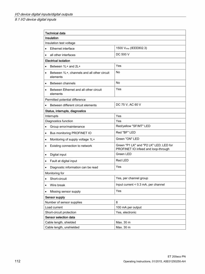
I/O device digital inputs/digital outputs 9.1 I/O device digital inputs
ET 200eco PN 112 Operating Instructions, 01/2015, A5E01250250-AH
Technical data Insulation Insulation test voltage
• Ethernet interface 1500 Vrms (IEEE802.3)
• all other interfaces DC 500 V
Electrical isolation
• Between 1L+ and 2L+ Yes
• Between 1L+, channels and all other circuit elements
No
• Between channels No
• Between Ethernet and all other circuit elements
Yes
Permitted potential difference
• Between different circuit elements DC 75 V, AC 60 V
Status, interrupts, diagnostics Interrupts Yes Diagnostics function Yes
• Group error/maintenance Red/yellow "SF/MT" LED
• Bus monitoring PROFINET IO Red "BF" LED
• Monitoring of supply voltage 1L+ Green "ON" LED
• Existing connection to network Green "P1 LK" and "P2 LK" LED; LED for PROFINET IO infeed and loop-through
• Digital input Green LED
• Fault at digital input Red LED
• Diagnostic information can be read Yes
Monitoring for
• Short-circuit Yes, per channel group
• Wire break Input current < 0.3 mA, per channel
• Missing sensor supply Yes
Sensor supply Number of sensor supplies 8 Load current 100 mA per output Short-circuit protection Yes, electronic Sensor selection data Cable length, shielded Max. 30 m Cable length, unshielded Max. 30 m
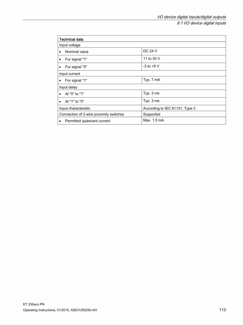
I/O device digital inputs/digital outputs 9.1 I/O device digital inputs
ET 200eco PN Operating Instructions, 01/2015, A5E01250250-AH 113
Technical data Input voltage
• Nominal value DC 24 V
• For signal "1" 11 to 30 V
• For signal "0" -3 to +5 V
Input current
• For signal "1" Typ. 7 mA
Input delay
• At "0" to "1" Typ. 3 ms
• At "1" to "0" Typ. 3 ms
Input characteristic According to IEC 61131, Type 3 Connection of 2-wire proximity switches Supported
• Permitted quiescent current Max. 1.5 mA

I/O device digital inputs/digital outputs 9.1 I/O device digital inputs
ET 200eco PN 114 Operating Instructions, 01/2015, A5E01250250-AH
9.1.4 Parameter overview digital inputs
Parameters for 8 DI DC 24V 4×M12 (6ES7141-6BF00-0AB0) and for 8 DI DC 24V 8×M12 (6ES7141-6BG00-0AB0) Parameter Range of values Default setting Range of effectiveness Group diagnostics • Disable
• Enable
Disable Device
Diagnostics: Missing 1L+ • Disable • Enable
Disable Device
Diagnostics: Wire break at inputs 0 to 7 (channels 0 to 7)
• Disable • Enable
Disable Channel
Diagnostics: Short-circuit to M, inputs 0,4/1,5/2,6/3,7 (channels 0,4/1,5/2,6/3,7)
• Disable • Enable
Disable Channel group
Parameters for 16 DI DC 24V 8×M12 (6ES7141-6BH00-0AB0) Parameter Range of values Default setting Range of effectiveness Group diagnostics • Disable
• Enable
Disable Device
Diagnostics: Missing 1L+ • Disable • Enable
Disable Device
Diagnostics: Wire break at inputs 0 to 15 (channels 0 to 15)
• Disable • Enable
Disable Channel
Diagnostics: Short-circuit to M, inputs 0,8/1,9/2,10/3,11/4,12/5,13/6,14/7,15 (channels 0,8/1,9/2,10/3,11/4,12/5,13/6,14/7,15)
• Disable • Enable
Disable Channel group
I/O device digital inputs/digital outputs 9.2 I/O device digital outputs
ET 200eco PN Operating Instructions, 01/2015, A5E01250250-AH 115
9.2 I/O device digital outputs
9.2.1 I/O device 8 DO DC 24 V/1.3A 4xM12
Order number 6ES7142-6BF00-0AB0
Properties The 8 DO DC 24V/1,3A 4×M12 I/O device has the following properties:
8 digital outputs
Dimensions 30 x 200 mm, dual assignment of the sockets
Output current: 1.3 A per output
Rated load voltage DC 24 V
Suitable for solenoid valves, DC contactors, and indicator lights
Diagnostics
– "Missing 1L+ or 2L+" for the I/O device
– "Wire break at outputs" per channel
– "Short-circuit to M at outputs" per channel
Parameterizable response to CPU/Master STOP
Prioritized startup
Media redundancy
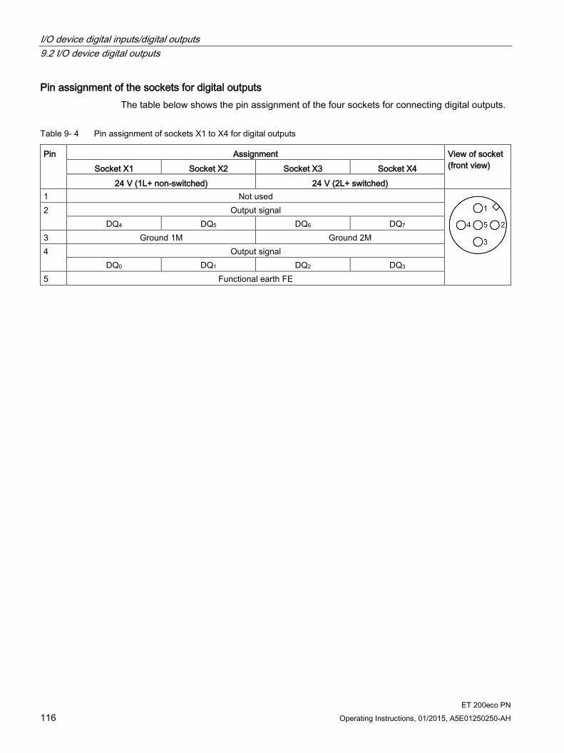
I/O device digital inputs/digital outputs 9.2 I/O device digital outputs
ET 200eco PN 116 Operating Instructions, 01/2015, A5E01250250-AH
Pin assignment of the sockets for digital outputs The table below shows the pin assignment of the four sockets for connecting digital outputs.
Table 9- 4 Pin assignment of sockets X1 to X4 for digital outputs
Pin Assignment View of socket (front view) Socket X1 Socket X2 Socket X3 Socket X4
24 V (1L+ non-switched) 24 V (2L+ switched) 1 Not used
2 Output signal DQ4 DQ5 DQ6 DQ7
3 Ground 1M Ground 2M 4 Output signal
DQ0 DQ1 DQ2 DQ3 5 Functional earth FE
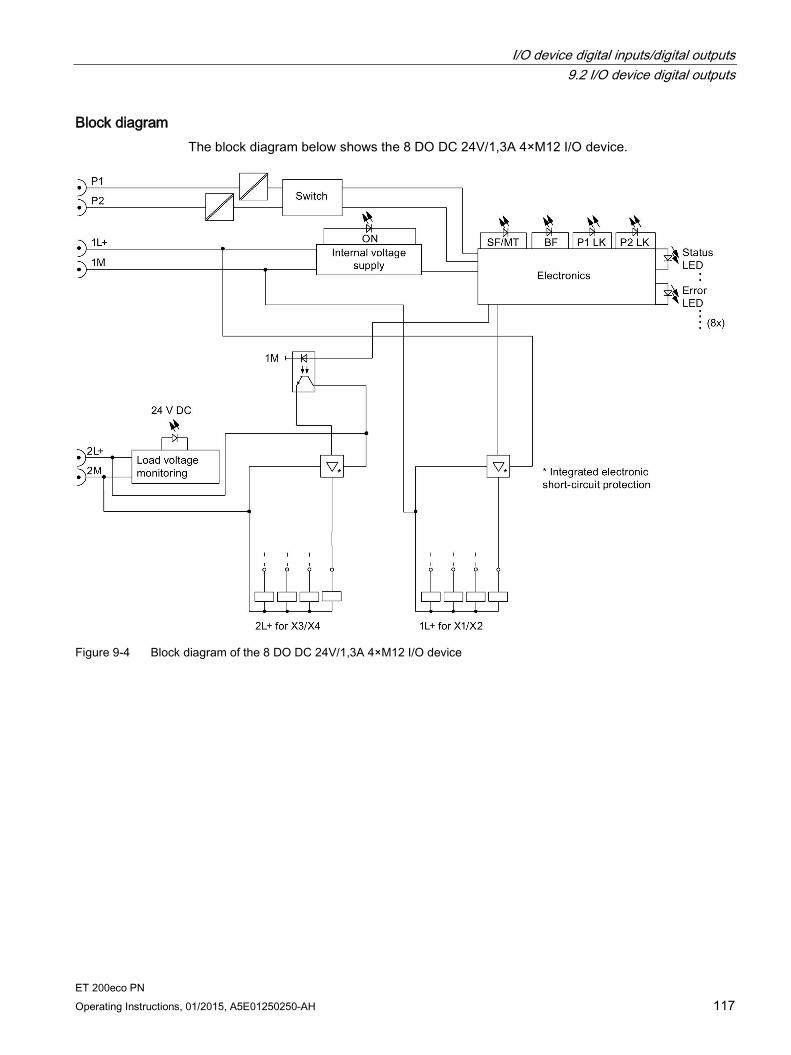
I/O device digital inputs/digital outputs 9.2 I/O device digital outputs
ET 200eco PN Operating Instructions, 01/2015, A5E01250250-AH 117
Block diagram The block diagram below shows the 8 DO DC 24V/1,3A 4×M12 I/O device.
Figure 9-4 Block diagram of the 8 DO DC 24V/1,3A 4×M12 I/O device
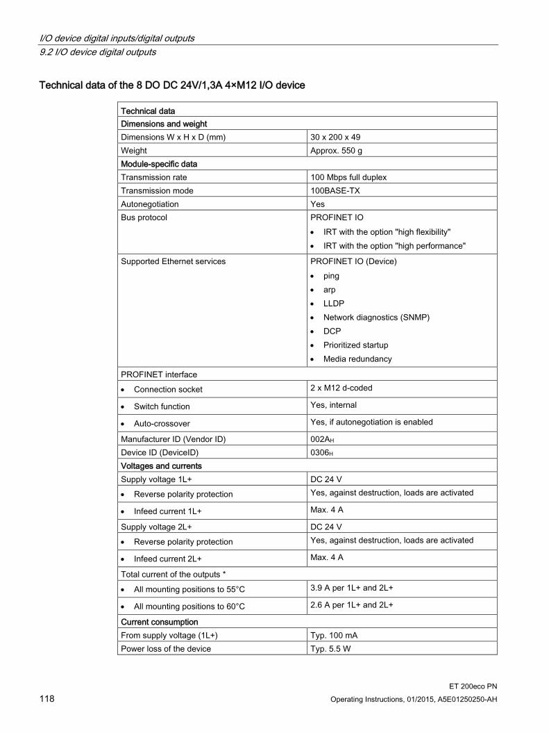
I/O device digital inputs/digital outputs 9.2 I/O device digital outputs
ET 200eco PN 118 Operating Instructions, 01/2015, A5E01250250-AH
Technical data of the 8 DO DC 24V/1,3A 4×M12 I/O device Technical data Dimensions and weight Dimensions W x H x D (mm) 30 x 200 x 49 Weight Approx. 550 g Module-specific data Transmission rate 100 Mbps full duplex Transmission mode 100BASE-TX Autonegotiation Yes Bus protocol PROFINET IO
• IRT with the option "high flexibility" • IRT with the option "high performance"
Supported Ethernet services PROFINET IO (Device) • ping • arp • LLDP • Network diagnostics (SNMP) • DCP • Prioritized startup • Media redundancy
PROFINET interface
• Connection socket 2 x M12 d-coded
• Switch function Yes, internal
• Auto-crossover Yes, if autonegotiation is enabled
Manufacturer ID (Vendor ID) 002AH Device ID (DeviceID) 0306H Voltages and currents Supply voltage 1L+ DC 24 V
• Reverse polarity protection Yes, against destruction, loads are activated
• Infeed current 1L+ Max. 4 A
Supply voltage 2L+ DC 24 V
• Reverse polarity protection Yes, against destruction, loads are activated
• Infeed current 2L+ Max. 4 A
Total current of the outputs *
• All mounting positions to 55°C 3.9 A per 1L+ and 2L+
• All mounting positions to 60°C 2.6 A per 1L+ and 2L+
Current consumption From supply voltage (1L+) Typ. 100 mA Power loss of the device Typ. 5.5 W
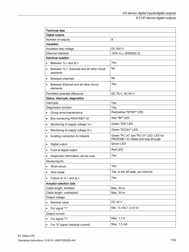
I/O device digital inputs/digital outputs 9.2 I/O device digital outputs
ET 200eco PN Operating Instructions, 01/2015, A5E01250250-AH 119
Technical data Digital outputs Number of outputs 8 Insulation Insulation test voltage DC 500 V Ethernet interface 1500 Vrms (IEEE802.3) Electrical isolation
• Between 1L+ and 2L+ Yes
• Between 1L+, channels and all other circuit elements
No
• Between channels No
• Between Ethernet and all other circuit elements
Yes
Permitted potential difference DC 75 V, AC 60 V Status, interrupts, diagnostics Interrupts Yes Diagnostics function Yes
• Group error/maintenance Red/yellow "SF/MT" LED
• Bus monitoring PROFINET IO Red "BF" LED
• Monitoring of supply voltage 1L+ Green "ON" LED
• Monitoring of supply voltage 2L+ Green "DC24V" LED
• Existing connection to network Green "P1 LK" and "P2 LK" LED; LED for PROFINET IO infeed and loop-through
• Digital output Green LED
• Fault at digital output Red LED
• Diagnostic information can be read Yes
Monitoring for
• Short-circuit Yes
• Wire break Yes, in the off state, per channel
• Failure of 1L+ and 2L+ Yes
Actuator selection data Cable length, shielded Max. 30 m Cable length, unshielded Max. 30 m Output voltage
• Nominal value DC 24 V
• For signal "1" Min. 1L+/2L+ (-0.8 V)
Output current
• For signal "1" Max. 1.3 A
• For "0" signal (residual current) Max. 1.5 mA

I/O device digital inputs/digital outputs 9.2 I/O device digital outputs
ET 200eco PN 120 Operating Instructions, 01/2015, A5E01250250-AH
Technical data Load resistance range 22 Ω to 3.3 kΩ Lamp load Max. 5 W Parallel wiring of two outputs
• To increase performance No
• For redundant control of a load Supported
Controlling of a digital input Yes Switching frequency
• With resistive load Max. 100 Hz
• With inductive load Max. 0.5 Hz
• With lamp load Max. 1 Hz
Limiting of the inductive shutdown voltage to lamp load
Typ. 1L+/2L+ (-47 V)
Short-circuit protection of the output Yes, electronic
• Response threshold Typ. 1.8 A (per channel)
* Make allowances for the maximum total current when configuring the module.
9.2.2 I/O device 8 DO DC 24 V/0.5A 4xM12
Order number 6ES7142-6BF50-0AB0
Properties The 8 DO DC 24V/0,5A 4×M12 I/O device has the following properties:
8 digital outputs
Dimensions 30 x 200 mm, dual assignment of the sockets
Output current: 0.5 A per output
Rated load voltage DC 24 V
Suitable for solenoid valves, DC contactors, and indicator lights
Diagnostics
– "Missing 1L+ or 2L+" for the I/O device
– "Wire break at outputs" per channel
– "Short-circuit to M at outputs" per channel
Parameterizable response to CPU/Master STOP
Prioritized startup
Media redundancy
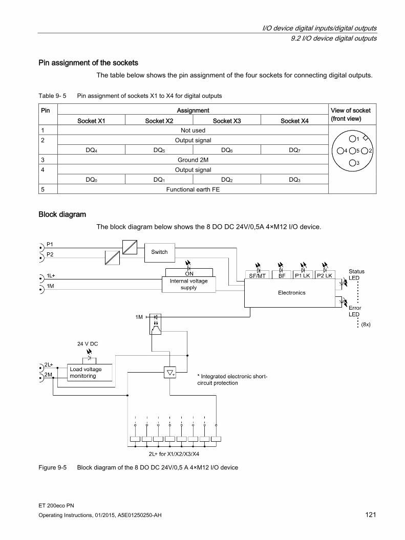
I/O device digital inputs/digital outputs 9.2 I/O device digital outputs
ET 200eco PN Operating Instructions, 01/2015, A5E01250250-AH 121
Pin assignment of the sockets The table below shows the pin assignment of the four sockets for connecting digital outputs.
Table 9- 5 Pin assignment of sockets X1 to X4 for digital outputs
Pin Assignment View of socket (front view) Socket X1 Socket X2 Socket X3 Socket X4
1 Not used
2 Output signal DQ4 DQ5 DQ6 DQ7
3 Ground 2M 4 Output signal
DQ0 DQ1 DQ2 DQ3 5 Functional earth FE
Block diagram The block diagram below shows the 8 DO DC 24V/0,5A 4×M12 I/O device.
Figure 9-5 Block diagram of the 8 DO DC 24V/0,5 A 4×M12 I/O device
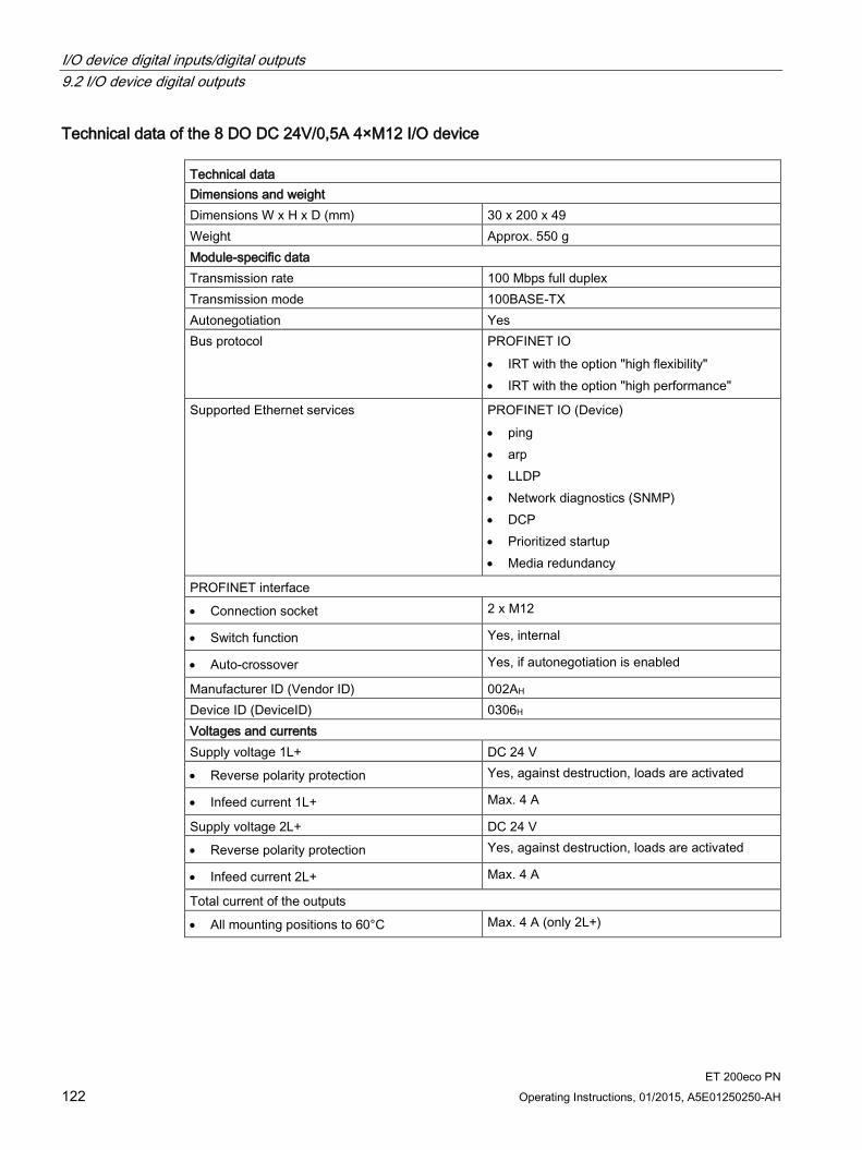
I/O device digital inputs/digital outputs 9.2 I/O device digital outputs
ET 200eco PN 122 Operating Instructions, 01/2015, A5E01250250-AH
Technical data of the 8 DO DC 24V/0,5A 4×M12 I/O device Technical data Dimensions and weight Dimensions W x H x D (mm) 30 x 200 x 49 Weight Approx. 550 g Module-specific data Transmission rate 100 Mbps full duplex Transmission mode 100BASE-TX Autonegotiation Yes Bus protocol PROFINET IO
• IRT with the option "high flexibility" • IRT with the option "high performance"
Supported Ethernet services PROFINET IO (Device) • ping • arp • LLDP • Network diagnostics (SNMP) • DCP • Prioritized startup • Media redundancy
PROFINET interface
• Connection socket 2 x M12
• Switch function Yes, internal
• Auto-crossover Yes, if autonegotiation is enabled
Manufacturer ID (Vendor ID) 002AH Device ID (DeviceID) 0306H Voltages and currents Supply voltage 1L+ DC 24 V
• Reverse polarity protection Yes, against destruction, loads are activated
• Infeed current 1L+ Max. 4 A
Supply voltage 2L+ DC 24 V
• Reverse polarity protection Yes, against destruction, loads are activated
• Infeed current 2L+ Max. 4 A
Total current of the outputs
• All mounting positions to 60°C Max. 4 A (only 2L+)
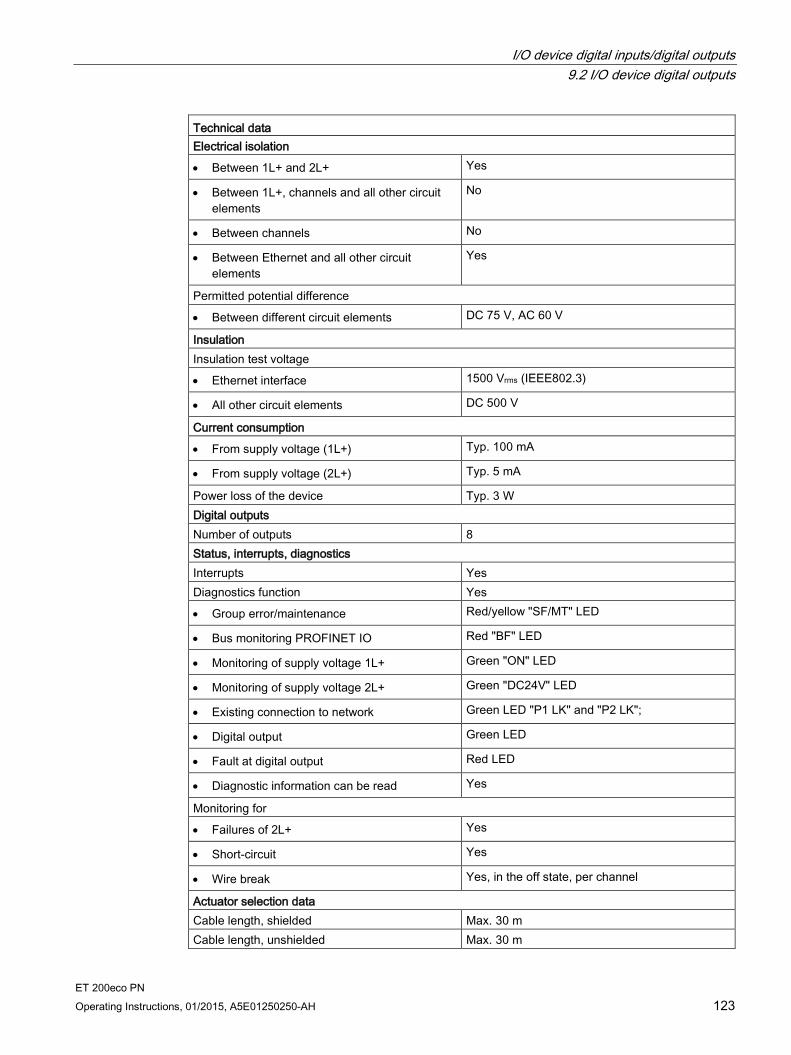
I/O device digital inputs/digital outputs 9.2 I/O device digital outputs
ET 200eco PN Operating Instructions, 01/2015, A5E01250250-AH 123
Technical data Electrical isolation
• Between 1L+ and 2L+ Yes
• Between 1L+, channels and all other circuit elements
No
• Between channels No
• Between Ethernet and all other circuit elements
Yes
Permitted potential difference
• Between different circuit elements DC 75 V, AC 60 V
Insulation Insulation test voltage
• Ethernet interface 1500 Vrms (IEEE802.3)
• All other circuit elements DC 500 V
Current consumption
• From supply voltage (1L+) Typ. 100 mA
• From supply voltage (2L+) Typ. 5 mA
Power loss of the device Typ. 3 W Digital outputs Number of outputs 8 Status, interrupts, diagnostics Interrupts Yes Diagnostics function Yes
• Group error/maintenance Red/yellow "SF/MT" LED
• Bus monitoring PROFINET IO Red "BF" LED
• Monitoring of supply voltage 1L+ Green "ON" LED
• Monitoring of supply voltage 2L+ Green "DC24V" LED
• Existing connection to network Green LED "P1 LK" and "P2 LK";
• Digital output Green LED
• Fault at digital output Red LED
• Diagnostic information can be read Yes
Monitoring for
• Failures of 2L+ Yes
• Short-circuit Yes
• Wire break Yes, in the off state, per channel
Actuator selection data Cable length, shielded Max. 30 m Cable length, unshielded Max. 30 m
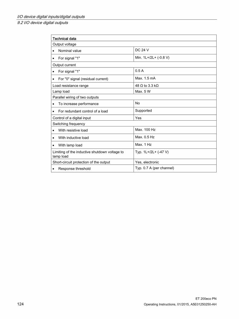
I/O device digital inputs/digital outputs 9.2 I/O device digital outputs
ET 200eco PN 124 Operating Instructions, 01/2015, A5E01250250-AH
Technical data Output voltage
• Nominal value DC 24 V
• For signal "1" Min. 1L+/2L+ (-0.8 V)
Output current
• For signal "1" 0.5 A
• For "0" signal (residual current) Max. 1.5 mA
Load resistance range 48 Ω to 3.3 kΩ Lamp load Max. 5 W Parallel wiring of two outputs
• To increase performance No
• For redundant control of a load Supported
Control of a digital input Yes Switching frequency
• With resistive load Max. 100 Hz
• With inductive load Max. 0.5 Hz
• With lamp load Max. 1 Hz
Limiting of the inductive shutdown voltage to lamp load
Typ. 1L+/2L+ (-47 V)
Short-circuit protection of the output Yes, electronic
• Response threshold Typ. 0.7 A (per channel)

I/O device digital inputs/digital outputs 9.2 I/O device digital outputs
ET 200eco PN Operating Instructions, 01/2015, A5E01250250-AH 125
9.2.3 I/O device 8 DO DC 24 V/1.3A 8xM12
Order number 6ES7142-6BG00-0AB0
Properties The 8 DO DC 24V/1,3A 8×M12 I/O device has the following properties:
8 digital outputs
Dimensions 60 x 175 mm, single assignment of the sockets
Output current: 1.3 A per output
Rated load voltage DC 24 V
Suitable for solenoid valves, DC contactors, and indicator lights
Diagnostics
– "Missing 1L+ or 2L+" for the I/O device
– "Wire break at outputs" per channel
– "Short-circuit to M at outputs" per channel
Parameterizable response to CPU/Master STOP
Prioritized startup
Media redundancy
Pin assignment of the sockets The table below shows the pin assignment of the eight sockets for connecting digital outputs.
Table 9- 6 Pin assignment of sockets X1 to X8 for digital outputs
Pin Assignment View of socket (front view) Socket X1 Socket X2 Socket X3 Socket X4 Socket X5 Socket X6 Socket X7 Socket X8
24 V (1L+ non-switched) 24 V (2L+ switched) 1 Not used
2 Not used 3 Ground 1M Ground 2M 4 Output signal
DQ0 DQ1 DQ2 DQ3 DQ4 DQ5 DQ6 DQ7 5 Functional earth FE
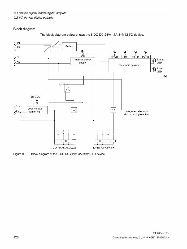
I/O device digital inputs/digital outputs 9.2 I/O device digital outputs
ET 200eco PN 126 Operating Instructions, 01/2015, A5E01250250-AH
Block diagram The block diagram below shows the 8 DO DC 24V/1,3A 8×M12 I/O device.
Figure 9-6 Block diagram of the 8 DO DC 24V/1,3A 8×M12 I/O device

I/O device digital inputs/digital outputs 9.2 I/O device digital outputs
ET 200eco PN Operating Instructions, 01/2015, A5E01250250-AH 127
Technical data of the 8 DO DC 24V/1,3A 8×M12 I/O device Technical data Dimensions and weight Dimensions W x H x D (mm) 60 x 175 x 49 Weight Approx. 910 g Module-specific data Transmission rate 100 Mbps full duplex Transmission mode 100BASE-TX Autonegotiation Yes Bus protocol PROFINET IO
• IRT with the option "high flexibility" • IRT with the option "high performance"
Supported Ethernet services PROFINET IO (Device) • ping • arp • LLDP • Network diagnostics (SNMP) • DCP • Prioritized startup • Media redundancy
PROFINET interface
• Connection socket 2 x M12 d-coded
• Switch function Yes, internal
• Auto-crossover Yes, if autonegotiation is enabled
Manufacturer ID (Vendor ID) 002AH Device ID (DeviceID) 0306H Voltages and currents Supply voltage 1L+ DC 24 V
• Reverse polarity protection Yes, against destruction, loads are activated
• Infeed current 1L+ Max. 4 A
Supply voltage 2L+ DC 24 V
• Reverse polarity protection Yes, against destruction, loads are activated
• Infeed current 2L+ Max. 4 A
Total current of the outputs *
• All mounting positions to 60°C Max. 3.9 A per 1L+ and 2L+
Current consumption From supply voltage (1L+) Typ. 100 mA From supply voltage (2L+) Typ. 5 mA Power loss of the device Typ. 5.5 W

I/O device digital inputs/digital outputs 9.2 I/O device digital outputs
ET 200eco PN 128 Operating Instructions, 01/2015, A5E01250250-AH
Technical data Digital outputs Number of outputs 8 Insulation Insulation test voltage
• Ethernet interface 1500 Vrms (IEEE802.3)
• All other circuit elements DC 500 V
Electrical isolation
• Between 1L+ and 2L+ Yes
• Between 1L+, channels and all other circuit elements
No
• Between channels No
• Between Ethernet and all other circuit elements
Yes
Permitted potential difference
• Between different circuit elements DC 75 V, AC 60 V
Status, interrupts, diagnostics Interrupts Yes Diagnostics function Yes
• Group error/maintenance Red/yellow "SF/MT" LED
• Bus monitoring PROFINET IO Red "BF" LED
• Monitoring of supply voltage 1L+ Green "ON" LED
• Monitoring of supply voltage 2L+ Green "DC24V" LED
• Existing connection to network Green "P1 LK" and "P2 LK" LED; LED for PROFINET IO infeed and loop-through
• Digital output Green LED
• Fault at digital output Red LED
• Diagnostic information can be read Yes
Monitoring for
• Failure of 1L+ and 2L+ Yes
• Short-circuit Yes, per channel
• Wire break Yes, in the off state, per channel
Actuator selection data Cable length, shielded Max. 30 m Cable length, unshielded Max. 30 m Output voltage
• Nominal value DC 24 V
• For signal "1" Min. 1L+/2L+ (-0.8 V)
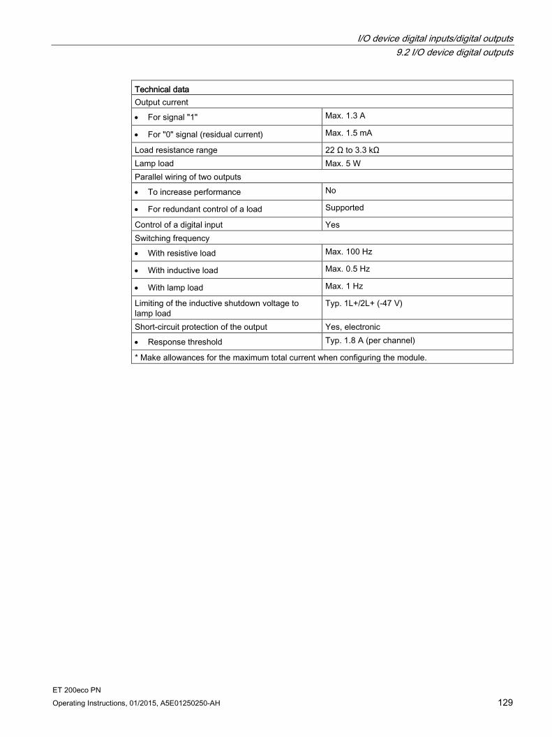
I/O device digital inputs/digital outputs 9.2 I/O device digital outputs
ET 200eco PN Operating Instructions, 01/2015, A5E01250250-AH 129
Technical data Output current
• For signal "1" Max. 1.3 A
• For "0" signal (residual current) Max. 1.5 mA
Load resistance range 22 Ω to 3.3 kΩ Lamp load Max. 5 W Parallel wiring of two outputs
• To increase performance No
• For redundant control of a load Supported
Control of a digital input Yes Switching frequency
• With resistive load Max. 100 Hz
• With inductive load Max. 0.5 Hz
• With lamp load Max. 1 Hz
Limiting of the inductive shutdown voltage to lamp load
Typ. 1L+/2L+ (-47 V)
Short-circuit protection of the output Yes, electronic
• Response threshold Typ. 1.8 A (per channel)
* Make allowances for the maximum total current when configuring the module.
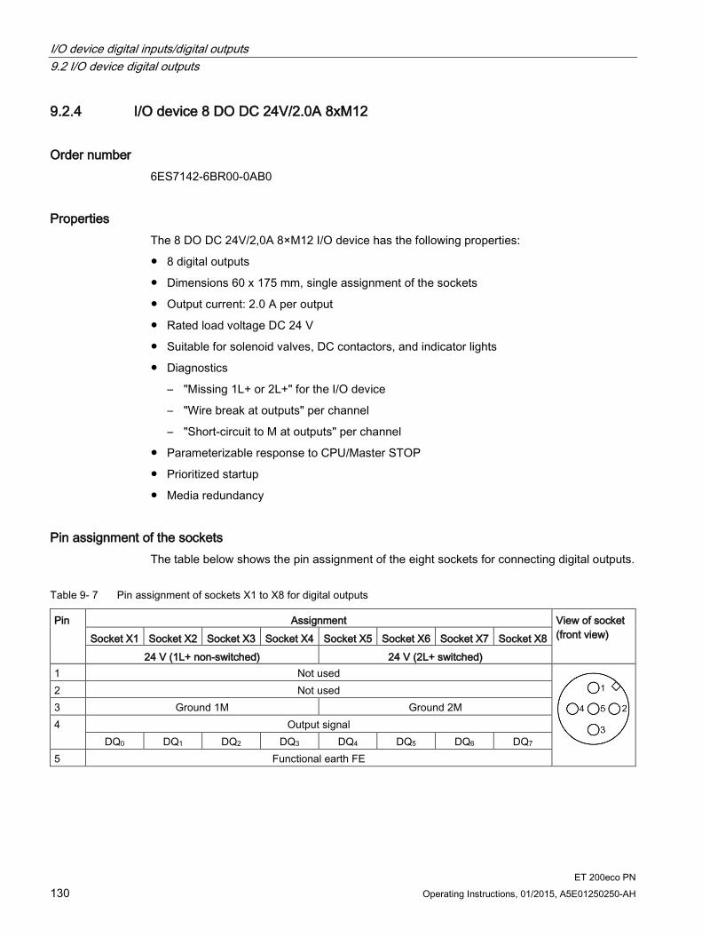
I/O device digital inputs/digital outputs 9.2 I/O device digital outputs
ET 200eco PN 130 Operating Instructions, 01/2015, A5E01250250-AH
9.2.4 I/O device 8 DO DC 24V/2.0A 8xM12
Order number 6ES7142-6BR00-0AB0
Properties The 8 DO DC 24V/2,0A 8×M12 I/O device has the following properties:
8 digital outputs
Dimensions 60 x 175 mm, single assignment of the sockets
Output current: 2.0 A per output
Rated load voltage DC 24 V
Suitable for solenoid valves, DC contactors, and indicator lights
Diagnostics
– "Missing 1L+ or 2L+" for the I/O device
– "Wire break at outputs" per channel
– "Short-circuit to M at outputs" per channel
Parameterizable response to CPU/Master STOP
Prioritized startup
Media redundancy
Pin assignment of the sockets The table below shows the pin assignment of the eight sockets for connecting digital outputs.
Table 9- 7 Pin assignment of sockets X1 to X8 for digital outputs
Pin Assignment View of socket (front view) Socket X1 Socket X2 Socket X3 Socket X4 Socket X5 Socket X6 Socket X7 Socket X8
24 V (1L+ non-switched) 24 V (2L+ switched) 1 Not used
2 Not used 3 Ground 1M Ground 2M 4 Output signal
DQ0 DQ1 DQ2 DQ3 DQ4 DQ5 DQ6 DQ7 5 Functional earth FE

I/O device digital inputs/digital outputs 9.2 I/O device digital outputs
ET 200eco PN Operating Instructions, 01/2015, A5E01250250-AH 131
Block diagram The block diagram below shows the 8 DO DC 24V/2,0A 8×M12 I/O device.
Figure 9-7 Block diagram of the 8 DO DC 24V/2,0A 8×M12 I/O device

I/O device digital inputs/digital outputs 9.2 I/O device digital outputs
ET 200eco PN 132 Operating Instructions, 01/2015, A5E01250250-AH
Technical data of the 8 DO DC 24V/2,0A 8×M12 I/O device Technical data Dimensions and weight Dimensions W x H x D (mm) 60 x 175 x 49 Weight Approx. 910 g Module-specific data Transmission rate 100 Mbps full duplex Transmission mode 100BASE-TX Autonegotiation Yes Bus protocol PROFINET IO
• IRT with the option "high flexibility" • IRT with the option "high performance"
Supported Ethernet services PROFINET IO (Device) • ping • arp • LLDP • Network diagnostics (SNMP) • DCP • Prioritized startup • Media redundancy
PROFINET interface
• Connection socket 2 x M12 d-coded
• Switch function Yes, internal
• Auto-crossover Yes, if autonegotiation is enabled
Manufacturer ID (Vendor ID) 002AH Device ID (DeviceID) 0306H Voltages and currents Supply voltage 1L+ DC 24 V
• Reverse polarity protection Yes, against destruction, loads are activated
• Infeed current 1L+ Max. 4 A
Supply voltage 2L+ DC 24 V
• Reverse polarity protection Yes, against destruction, loads are activated
• Infeed current 2L+ Max. 4 A
Total current of the outputs *
• All mounting positions to 60°C Max. 3.9 A 1L+ and max. 4 A 2L+
Current consumption From supply voltage (1L+) Typ. 100 mA From supply voltage (2L+) Typ. 5 mA Power loss of the device Typ. 5 W
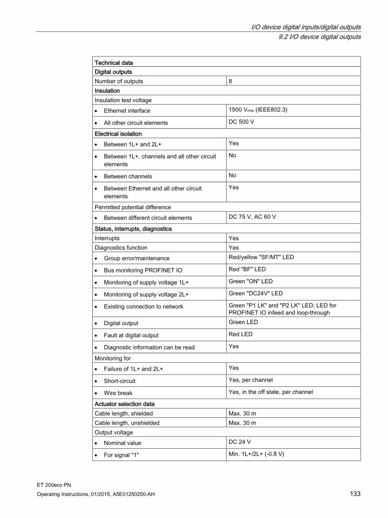
I/O device digital inputs/digital outputs 9.2 I/O device digital outputs
ET 200eco PN Operating Instructions, 01/2015, A5E01250250-AH 133
Technical data Digital outputs Number of outputs 8 Insulation Insulation test voltage
• Ethernet interface 1500 Vrms (IEEE802.3)
• All other circuit elements DC 500 V
Electrical isolation
• Between 1L+ and 2L+ Yes
• Between 1L+, channels and all other circuit elements
No
• Between channels No
• Between Ethernet and all other circuit elements
Yes
Permitted potential difference
• Between different circuit elements DC 75 V, AC 60 V
Status, interrupts, diagnostics Interrupts Yes Diagnostics function Yes
• Group error/maintenance Red/yellow "SF/MT" LED
• Bus monitoring PROFINET IO Red "BF" LED
• Monitoring of supply voltage 1L+ Green "ON" LED
• Monitoring of supply voltage 2L+ Green "DC24V" LED
• Existing connection to network Green "P1 LK" and "P2 LK" LED; LED for PROFINET IO infeed and loop-through
• Digital output Green LED
• Fault at digital output Red LED
• Diagnostic information can be read Yes
Monitoring for
• Failure of 1L+ and 2L+ Yes
• Short-circuit Yes, per channel
• Wire break Yes, in the off state, per channel
Actuator selection data Cable length, shielded Max. 30 m Cable length, unshielded Max. 30 m Output voltage
• Nominal value DC 24 V
• For signal "1" Min. 1L+/2L+ (-0.8 V)

I/O device digital inputs/digital outputs 9.2 I/O device digital outputs
ET 200eco PN 134 Operating Instructions, 01/2015, A5E01250250-AH
Technical data Output current
• For signal "1" 2.0 A
• For "0" signal (residual current) Max. 1.5 mA
Load resistance range 12 Ω to 3.3 kΩ Lamp load Max. 10 W Parallel wiring of two outputs
• To increase performance No
• For redundant control of a load Supported
Control of a digital input Yes Switching frequency
• With resistive load Max. 100 Hz
• With inductive load Max. 0.5 Hz
• With lamp load Max. 1 Hz
Limiting of the inductive shutdown voltage to lamp load
Typ. 1L+/2L+ (-47 V)
Short-circuit protection of the output Yes, electronic
• Response threshold Typ. 2.8 A (per channel)
* Make allowances for the maximum total current when configuring the module.
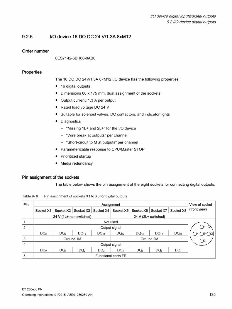
I/O device digital inputs/digital outputs 9.2 I/O device digital outputs
ET 200eco PN Operating Instructions, 01/2015, A5E01250250-AH 135
9.2.5 I/O device 16 DO DC 24 V/1.3A 8xM12
Order number 6ES7142-6BH00-0AB0
Properties The 16 DO DC 24V/1,3A 8×M12 I/O device has the following properties:
16 digital outputs
Dimensions 60 x 175 mm, dual assignment of the sockets
Output current: 1.3 A per output
Rated load voltage DC 24 V
Suitable for solenoid valves, DC contactors, and indicator lights
Diagnostics
– "Missing 1L+ and 2L+" for the I/O device
– "Wire break at outputs" per channel
– "Short-circuit to M at outputs" per channel
Parameterizable response to CPU/Master STOP
Prioritized startup
Media redundancy
Pin assignment of the sockets The table below shows the pin assignment of the eight sockets for connecting digital outputs.
Table 9- 8 Pin assignment of sockets X1 to X8 for digital outputs
Pin Assignment View of socket (front view) Socket X1 Socket X2 Socket X3 Socket X4 Socket X5 Socket X6 Socket X7 Socket X8
24 V (1L+ non-switched) 24 V (2L+ switched) 1 Not used
2 Output signal DQ8 DQ9 DQ10 DQ11 DQ12 DQ13 DQ14 DQ15
3 Ground 1M Ground 2M 4 Output signal
DQ0 DQ1 DQ2 DQ3 DQ4 DQ5 DQ6 DQ7 5 Functional earth FE
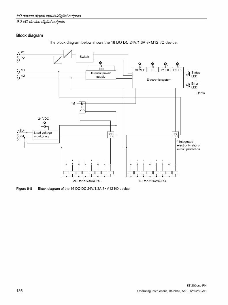
I/O device digital inputs/digital outputs 9.2 I/O device digital outputs
ET 200eco PN 136 Operating Instructions, 01/2015, A5E01250250-AH
Block diagram The block diagram below shows the 16 DO DC 24V/1,3A 8×M12 I/O device.
Figure 9-8 Block diagram of the 16 DO DC 24V/1,3A 8×M12 I/O device

I/O device digital inputs/digital outputs 9.2 I/O device digital outputs
ET 200eco PN Operating Instructions, 01/2015, A5E01250250-AH 137
Technical data of the 16 DO DC 24V/1,3A 8×M12 I/O device Technical data Dimensions and weight Dimensions W x H x D (mm) 60 x 175 x 49 Weight Approx. 910 g Module-specific data Transmission rate 100 Mbps full duplex Transmission mode 100BASE-TX Autonegotiation Yes Bus protocol PROFINET IO
• IRT with the option "high flexibility" • IRT with the option "high performance"
Supported Ethernet services PROFINET IO (Device) • ping • arp • LLDP • Network diagnostics (SNMP) • DCP • Prioritized startup • Media redundancy
PROFINET interface
• Connection socket 2 x M12 d-coded
• Switch function Yes, internal
• Auto-crossover Yes, if autonegotiation is enabled
Manufacturer ID (Vendor ID) 002AH Device ID (DeviceID) 0306H Voltages and currents Supply voltage 1L+ DC 24 V
• Reverse polarity protection Yes, against destruction, loads are activated
• Infeed current 1L+ Max. 4 A
Supply voltage 2L+ DC 24 V
• Reverse polarity protection Yes, against destruction, loads are activated
• Infeed current 2L+ Max. 4 A
Total current of the outputs *
• All mounting positions to 60°C Max. 3.9 A per 1L+ and 2L+
Current consumption From supply voltage (1L+) Typ. 100 mA From supply voltage (2L+) Typ. 5 mA Power loss of the device Typ. 5.5 W
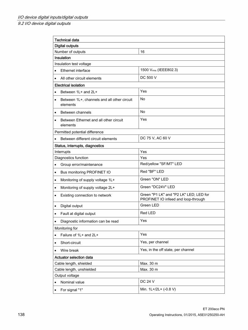
I/O device digital inputs/digital outputs 9.2 I/O device digital outputs
ET 200eco PN 138 Operating Instructions, 01/2015, A5E01250250-AH
Technical data Digital outputs Number of outputs 16 Insulation Insulation test voltage
• Ethernet interface 1500 Vrms (IEEE802.3)
• All other circuit elements DC 500 V
Electrical isolation
• Between 1L+ and 2L+ Yes
• Between 1L+, channels and all other circuit elements
No
• Between channels No
• Between Ethernet and all other circuit elements
Yes
Permitted potential difference
• Between different circuit elements DC 75 V, AC 60 V
Status, interrupts, diagnostics Interrupts Yes Diagnostics function Yes
• Group error/maintenance Red/yellow "SF/MT" LED
• Bus monitoring PROFINET IO Red "BF" LED
• Monitoring of supply voltage 1L+ Green "ON" LED
• Monitoring of supply voltage 2L+ Green "DC24V" LED
• Existing connection to network Green "P1 LK" and "P2 LK" LED; LED for PROFINET IO infeed and loop-through
• Digital output Green LED
• Fault at digital output Red LED
• Diagnostic information can be read Yes
Monitoring for
• Failure of 1L+ and 2L+ Yes
• Short-circuit Yes, per channel
• Wire break Yes, in the off state, per channel
Actuator selection data Cable length, shielded Max. 30 m Cable length, unshielded Max. 30 m Output voltage
• Nominal value DC 24 V
• For signal "1" Min. 1L+/2L+ (-0.8 V)

I/O device digital inputs/digital outputs 9.2 I/O device digital outputs
ET 200eco PN Operating Instructions, 01/2015, A5E01250250-AH 139
Technical data Output current
• For signal "1" Max. 1.3 A
• For "0" signal (residual current) Max. 1.5 mA
Load resistance range 22 Ω to 3.3 kΩ Lamp load Max. 5 W Parallel wiring of two outputs
• To increase performance No
• For redundant control of a load Supported
Control of a digital input Yes Switching frequency
• With resistive load Max. 100 Hz
• With inductive load Max. 0.5 Hz
• With lamp load Max. 1 Hz
Limiting of the inductive shutdown voltage to lamp load
Typ. 1L+/2L+ (-47 V)
Short-circuit protection of the output Yes, electronic
• Response threshold Typ. 1.8 A (per channel)
* Make allowances for the maximum total current when configuring the module.
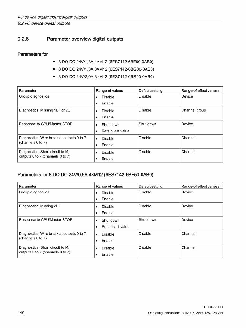
I/O device digital inputs/digital outputs 9.2 I/O device digital outputs
ET 200eco PN 140 Operating Instructions, 01/2015, A5E01250250-AH
9.2.6 Parameter overview digital outputs
Parameters for 8 DO DC 24V/1,3A 4×M12 (6ES7142-6BF00-0AB0)
8 DO DC 24V/1,3A 8×M12 (6ES7142-6BG00-0AB0)
8 DO DC 24V/2,0A 8×M12 (6ES7142-6BR00-0AB0)
Parameter Range of values Default setting Range of effectiveness Group diagnostics • Disable
• Enable
Disable Device
Diagnostics: Missing 1L+ or 2L+ • Disable • Enable
Disable Channel group
Response to CPU/Master STOP • Shut down • Retain last value
Shut down Device
Diagnostics: Wire break at outputs 0 to 7 (channels 0 to 7)
• Disable • Enable
Disable Channel
Diagnostics: Short circuit to M, outputs 0 to 7 (channels 0 to 7)
• Disable • Enable
Disable Channel
Parameters for 8 DO DC 24V/0,5A 4×M12 (6ES7142-6BF50-0AB0) Parameter Range of values Default setting Range of effectiveness Group diagnostics • Disable
• Enable
Disable Device
Diagnostics: Missing 2L+ • Disable • Enable
Disable Device
Response to CPU/Master STOP • Shut down • Retain last value
Shut down Device
Diagnostics: Wire break at outputs 0 to 7 (channels 0 to 7)
• Disable • Enable
Disable Channel
Diagnostics: Short circuit to M, outputs 0 to 7 (channels 0 to 7)
• Disable • Enable
Disable Channel
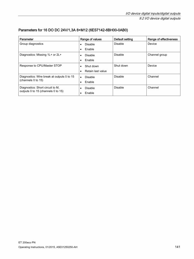
I/O device digital inputs/digital outputs 9.2 I/O device digital outputs
ET 200eco PN Operating Instructions, 01/2015, A5E01250250-AH 141
Parameters for 16 DO DC 24V/1,3A 8×M12 (6ES7142-6BH00-0AB0) Parameter Range of values Default setting Range of effectiveness Group diagnostics • Disable
• Enable
Disable Device
Diagnostics: Missing 1L+ or 2L+ • Disable • Enable
Disable Channel group
Response to CPU/Master STOP • Shut down • Retain last value
Shut down Device
Diagnostics: Wire break at outputs 0 to 15 (channels 0 to 15)
• Disable • Enable
Disable Channel
Diagnostics: Short circuit to M, outputs 0 to 15 (channels 0 to 15)
• Disable • Enable
Disable Channel
I/O device digital inputs/digital outputs 9.3 I/O device digital inputs/digital outputs
ET 200eco PN 142 Operating Instructions, 01/2015, A5E01250250-AH
9.3 I/O device digital inputs/digital outputs
9.3.1 I/O device 8 DIO DC 24V/1.3A 8xM12
Order number 6ES7147-6BG00-0AB0
Properties The 8 DIO DC 24V/1,3A 8×M12 I/O device has the following properties:
8 freely parameterizable digital inputs/outputs
Prioritized startup
Media redundancy
Dimensions 60 x 175 mm, single assignment of the sockets
Digital inputs
– Rated input voltage DC 24 V
– Suitable for switches and proximity switches
– Diagnostics
"Missing 1L+ or 2L+" for the I/O device
"Short-circuit to M at sensor supply", per channel group
"Wire break", per channel
Digital outputs
– Rated load voltage DC 24 V
– Output current: 1.3 A per output
– Suitable for solenoid valves, DC contactors, and indicator lights
– Diagnostics
"Missing 1L+ or 2L+" for the I/O device
"Wire break at outputs" per channel
"Short-circuit to M at outputs" per channel
– Parameterizable response to CPU/Master STOP for I/O device
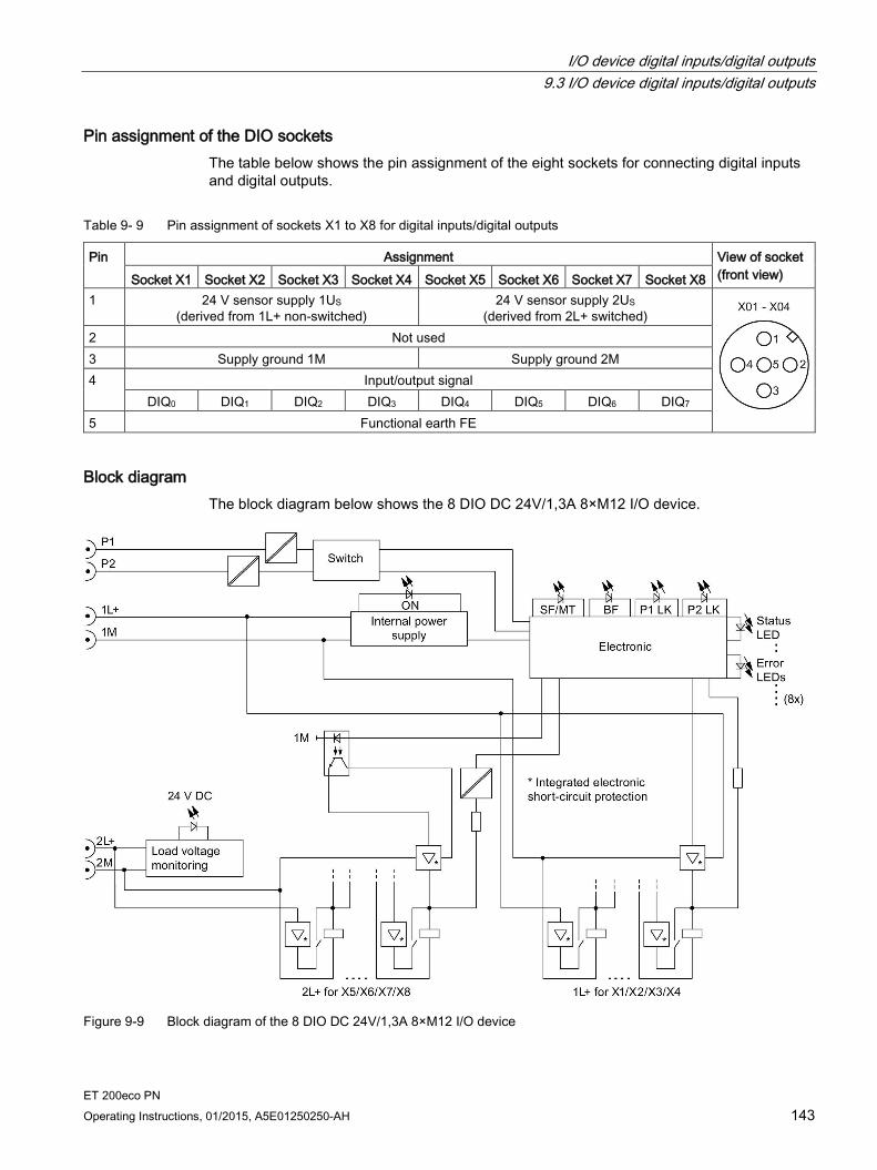
I/O device digital inputs/digital outputs 9.3 I/O device digital inputs/digital outputs
ET 200eco PN Operating Instructions, 01/2015, A5E01250250-AH 143
Pin assignment of the DIO sockets The table below shows the pin assignment of the eight sockets for connecting digital inputs and digital outputs.
Table 9- 9 Pin assignment of sockets X1 to X8 for digital inputs/digital outputs
Pin Assignment View of socket (front view) Socket X1 Socket X2 Socket X3 Socket X4 Socket X5 Socket X6 Socket X7 Socket X8
1 24 V sensor supply 1US (derived from 1L+ non-switched)
24 V sensor supply 2US (derived from 2L+ switched)
2 Not used 3 Supply ground 1M Supply ground 2M 4 Input/output signal
DIQ0 DIQ1 DIQ2 DIQ3 DIQ4 DIQ5 DIQ6 DIQ7 5 Functional earth FE
Block diagram The block diagram below shows the 8 DIO DC 24V/1,3A 8×M12 I/O device.
Figure 9-9 Block diagram of the 8 DIO DC 24V/1,3A 8×M12 I/O device
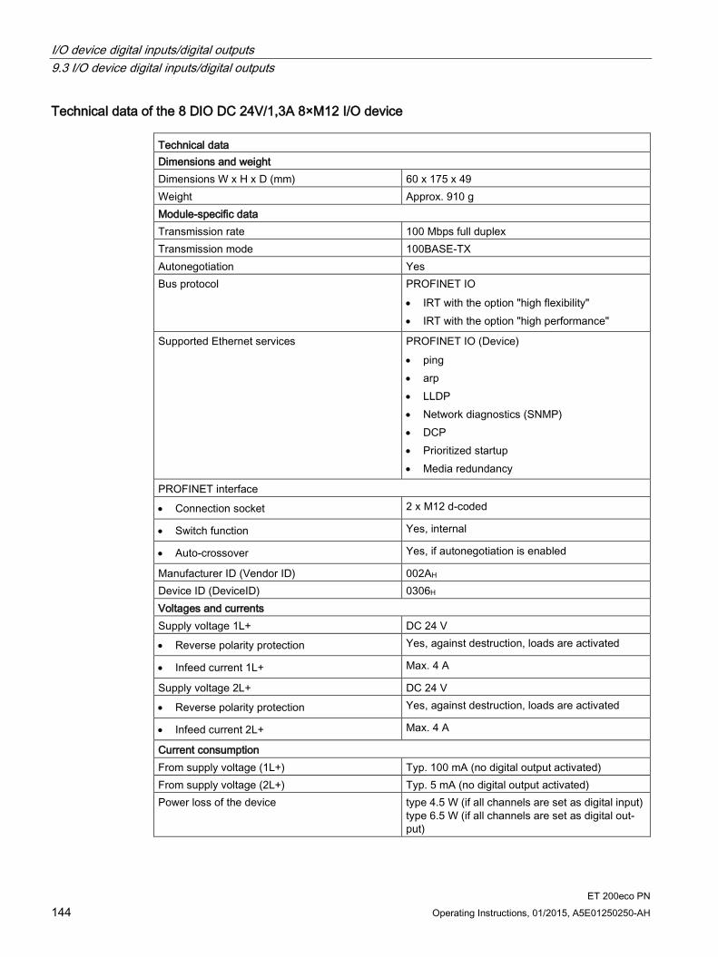
I/O device digital inputs/digital outputs 9.3 I/O device digital inputs/digital outputs
ET 200eco PN 144 Operating Instructions, 01/2015, A5E01250250-AH
Technical data of the 8 DIO DC 24V/1,3A 8×M12 I/O device Technical data Dimensions and weight Dimensions W x H x D (mm) 60 x 175 x 49 Weight Approx. 910 g Module-specific data Transmission rate 100 Mbps full duplex Transmission mode 100BASE-TX Autonegotiation Yes Bus protocol PROFINET IO
• IRT with the option "high flexibility" • IRT with the option "high performance"
Supported Ethernet services PROFINET IO (Device) • ping • arp • LLDP • Network diagnostics (SNMP) • DCP • Prioritized startup • Media redundancy
PROFINET interface
• Connection socket 2 x M12 d-coded
• Switch function Yes, internal
• Auto-crossover Yes, if autonegotiation is enabled
Manufacturer ID (Vendor ID) 002AH Device ID (DeviceID) 0306H Voltages and currents Supply voltage 1L+ DC 24 V
• Reverse polarity protection Yes, against destruction, loads are activated
• Infeed current 1L+ Max. 4 A
Supply voltage 2L+ DC 24 V
• Reverse polarity protection Yes, against destruction, loads are activated
• Infeed current 2L+ Max. 4 A
Current consumption From supply voltage (1L+) Typ. 100 mA (no digital output activated) From supply voltage (2L+) Typ. 5 mA (no digital output activated) Power loss of the device type 4.5 W (if all channels are set as digital input)
type 6.5 W (if all channels are set as digital out-put)

I/O device digital inputs/digital outputs 9.3 I/O device digital inputs/digital outputs
ET 200eco PN Operating Instructions, 01/2015, A5E01250250-AH 145
Technical data Total current of the outputs
• All mounting positions to 60°C Max. 3.9 A per 1L+ and 2L+
Digital inputs/digital outputs Number of configurable inputs/outputs 8 Number of inputs that can be controlled simultaneously
8, in all mounting positions
Insulation Insulation test voltage DC 500 V Ethernet interface 1500 Vrms (IEEE802.3) Electrical isolation
• Between 1L+ and 2L+ Yes
• Between 1L+, channels and all other circuit elements
No
• Between channels No
• Between Ethernet and all other circuit elements
Yes
Permitted potential difference DC 75 V, AC 60 V Status, interrupts, diagnostics Interrupts Yes Diagnostics function Yes
• Group error/maintenance Red/yellow "SF/MT" LED
• Bus monitoring PROFINET IO Red "BF" LED
• Monitoring of supply voltage 1L+ Green "ON" LED
• Existing connection to network Green "P1 LK" and "P2 LK" LED; LED for PROFINET IO infeed and loop-through
• Digital input Green LED
• Fault at digital input Red LED
• Digital output Green LED
• Fault at digital output Red LED
• Diagnostic information can be read Yes
Monitoring for
• Failure of 1L+ and 2L+ Yes
• Sensor supply short-circuit Yes, per channel
• Digital output short-circuit Yes, per channel
• Digital input wire break Yes, input current < 0.3 mA, per channel
• Digital output wire break Yes, in the off state, per channel

I/O device digital inputs/digital outputs 9.3 I/O device digital inputs/digital outputs
ET 200eco PN 146 Operating Instructions, 01/2015, A5E01250250-AH
Technical data Sensor supply Number of sensor supplies 8, 4×1L+ and 4×2L+
Note: The sensor supply is only available when the corresponding channel is parameterized as an "Input".
Load current 100 mA per output Short-circuit protection Yes, electronic Sensor selection data Cable length, shielded Max. 30 m Cable length, unshielded Max. 30 m Input voltage
• Nominal value 24 V DC
• For signal "1" 11 to 30 V
• For signal "0" -3 to +5 V
Input current
• For signal "1" Typ. 7 mA
Input delay
• At "0" to "1" Typ. 3 ms
• At "1" to "0" Typ. 3 ms
Input characteristic According to IEC 61131, Type 3 Connection of 2-wire proximity switches Supported
• Permitted quiescent current Max. 1.5 mA
Actuator selection data Cable length, shielded Max. 30 m Cable length, unshielded Max. 30 m Output voltage
• Nominal value 24 V DC
• For signal "1" Min. 1L+/2L+ (-0.8 V)
Output current
• For signal "1" Max. 1.3 A
• For "0" signal (residual current) Max. 1.5 mA
Load resistance range 22 Ω to 3.3 kΩ Lamp load Max. 5 W Parallel wiring of two outputs
• To increase performance No
• For redundant control of a load Supported
Control of a digital input Yes
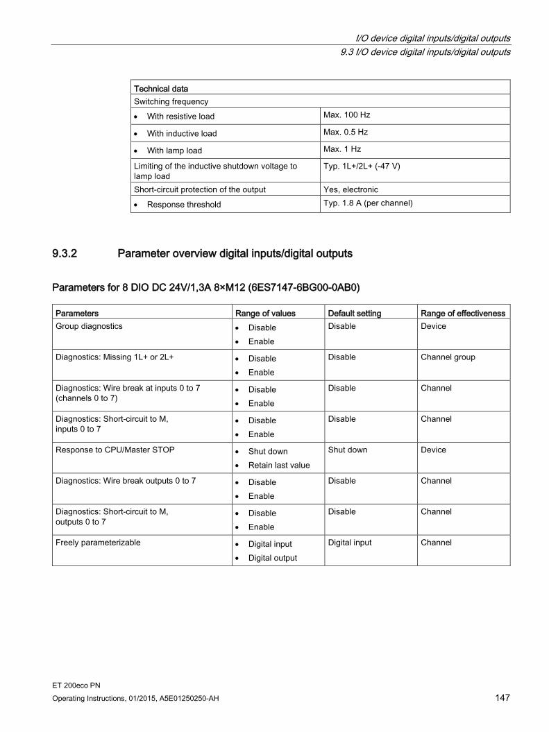
I/O device digital inputs/digital outputs 9.3 I/O device digital inputs/digital outputs
ET 200eco PN Operating Instructions, 01/2015, A5E01250250-AH 147
Technical data Switching frequency
• With resistive load Max. 100 Hz
• With inductive load Max. 0.5 Hz
• With lamp load Max. 1 Hz
Limiting of the inductive shutdown voltage to lamp load
Typ. 1L+/2L+ (-47 V)
Short-circuit protection of the output Yes, electronic
• Response threshold Typ. 1.8 A (per channel)
9.3.2 Parameter overview digital inputs/digital outputs
Parameters for 8 DIO DC 24V/1,3A 8×M12 (6ES7147-6BG00-0AB0) Parameters Range of values Default setting Range of effectiveness Group diagnostics • Disable
• Enable
Disable Device
Diagnostics: Missing 1L+ or 2L+ • Disable • Enable
Disable Channel group
Diagnostics: Wire break at inputs 0 to 7 (channels 0 to 7)
• Disable • Enable
Disable Channel
Diagnostics: Short-circuit to M, inputs 0 to 7
• Disable • Enable
Disable Channel
Response to CPU/Master STOP • Shut down • Retain last value
Shut down Device
Diagnostics: Wire break outputs 0 to 7 • Disable • Enable
Disable Channel
Diagnostics: Short-circuit to M, outputs 0 to 7
• Disable • Enable
Disable Channel
Freely parameterizable • Digital input • Digital output
Digital input Channel
ET 200eco PN 148 Operating Instructions, 01/2015, A5E01250250-AH
IO-Link Master 10 10.1 IO-Link Master
Order number 6ES7148-6JA00-0AB0
Properties The IO-Link Master 4 IO-L + 8 DI + 4 DO DC 24V/1,3A 8×M12 has the following properties: 4 IO-Link channels 8 digital inputs and 4 digital outputs Dimensions 60 x 175 mm, dual assignment of the sockets Prioritized startup Media redundancy (as of firmware V7.0) IO-Link channels
– 4 IO-Link Devices as 3-wire connection
– 4 Standard actuators/sensors
Digital inputs – Rated input voltage DC 24 V
– Suitable for switches and proximity switches
– Diagnostics
"Missing 2L+" for the I/O device "Short-circuit to M at sensor supply", per channel group "Wire break", per channel
– Channels 4 to 7 are diagnostics-capable, Channels 0 to 3 do not have diagnostics.
Digital outputs – Rated load voltage DC 24 V
– Output current: 1.3 A per output
– Suitable for solenoid valves, DC contactors, and indicator lights
– Diagnostics
"Missing 2L+" for the I/O device "Wire break at outputs" per channel "Short-circuit to M at outputs" per channel
– Parameterizable response to CPU/Master STOP

IO-Link Master 10.1 IO-Link Master
ET 200eco PN Operating Instructions, 01/2015, A5E01250250-AH 149
General pin assignment
Table 10- 1 Pin assignment of sockets X1 to X4 for IO-Link Master and digital inputs
Pin Assignment View of socket (front view) Socket X1 Socket X2 Socket X3 Socket X4
1 24 V sensor supply 1US(derived from 1L+ non-switched)
2 Input signal DI0 DI1 DI2 DI3
3 Sensor supply ground 1M 4 IO-Link port 1 IO-Link port 2 IO-Link port 3 IO-Link port 4 5 Not used
Table 10- 2 Pin assignment of the sockets X5 to X6 for digital inputs
Pin Assignment View of socket (front view) Socket X5 Socket X6
1 24 V sensor supply 1US(derived from 1L+ non-switched)
2 Input signal DI5 DI7
3 Sensor supply ground 1M 4 Input signal
DI4 DI6 5 Functional earth FE
Table 10- 3 Pin assignment of sockets X7 and X8 for digital outputs
Pin Assignment View of socket (front view) Socket X7 (2L+ switched) Socket X8 (2L+ switched)
1 Not used
2 Output signal DQ1 DQ3
3 Supply ground 2M 4 Output signal
DQ0 DQ2 5 Functional earth FE

IO-Link Master 10.1 IO-Link Master
ET 200eco PN 150 Operating Instructions, 01/2015, A5E01250250-AH
Block diagram The figure below shows the block diagram of the IO-Link Master 4 IO-L + 8 DI + 4 DO DC 24V/1,3A 8×M12.
Figure 10-1 Block diagram of the IO-Link Master 4 IO-L + 8 DI + 4 DO DC 24V/1,3A 8×M12
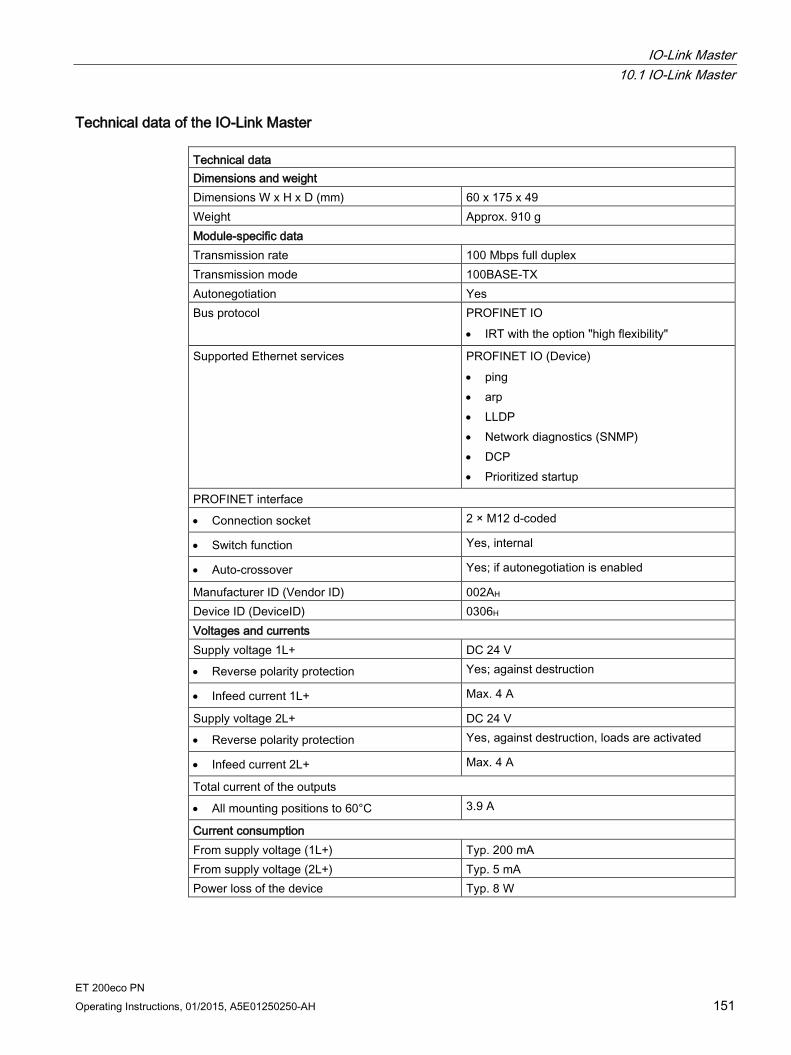
IO-Link Master 10.1 IO-Link Master
ET 200eco PN Operating Instructions, 01/2015, A5E01250250-AH 151
Technical data of the IO-Link Master Technical data Dimensions and weight Dimensions W x H x D (mm) 60 x 175 x 49 Weight Approx. 910 g Module-specific data Transmission rate 100 Mbps full duplex Transmission mode 100BASE-TX Autonegotiation Yes Bus protocol PROFINET IO
• IRT with the option "high flexibility"
Supported Ethernet services PROFINET IO (Device) • ping • arp • LLDP • Network diagnostics (SNMP) • DCP • Prioritized startup
PROFINET interface
• Connection socket 2 × M12 d-coded
• Switch function Yes, internal
• Auto-crossover Yes; if autonegotiation is enabled
Manufacturer ID (Vendor ID) 002AH Device ID (DeviceID) 0306H Voltages and currents Supply voltage 1L+ DC 24 V
• Reverse polarity protection Yes; against destruction
• Infeed current 1L+ Max. 4 A
Supply voltage 2L+ DC 24 V
• Reverse polarity protection Yes, against destruction, loads are activated
• Infeed current 2L+ Max. 4 A
Total current of the outputs
• All mounting positions to 60°C 3.9 A
Current consumption From supply voltage (1L+) Typ. 200 mA From supply voltage (2L+) Typ. 5 mA Power loss of the device Typ. 8 W
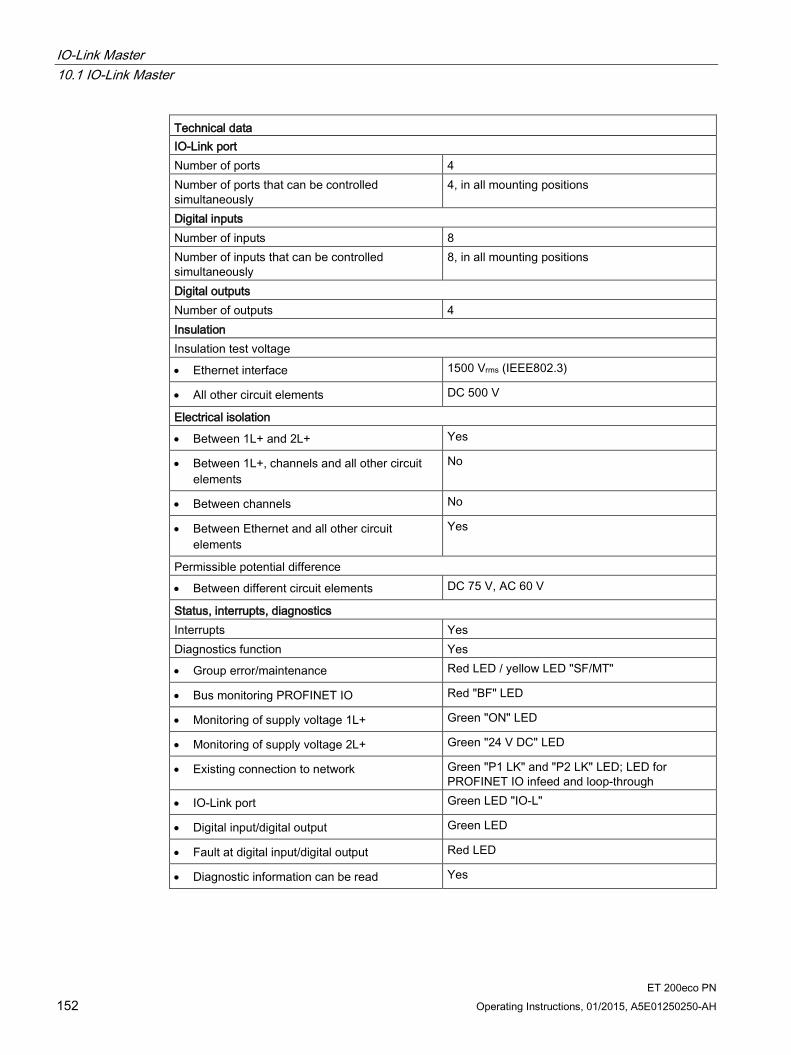
IO-Link Master 10.1 IO-Link Master
ET 200eco PN 152 Operating Instructions, 01/2015, A5E01250250-AH
Technical data IO-Link port Number of ports 4 Number of ports that can be controlled simultaneously
4, in all mounting positions
Digital inputs Number of inputs 8 Number of inputs that can be controlled simultaneously
8, in all mounting positions
Digital outputs Number of outputs 4 Insulation Insulation test voltage
• Ethernet interface 1500 Vrms (IEEE802.3)
• All other circuit elements DC 500 V
Electrical isolation
• Between 1L+ and 2L+ Yes
• Between 1L+, channels and all other circuit elements
No
• Between channels No
• Between Ethernet and all other circuit elements
Yes
Permissible potential difference
• Between different circuit elements DC 75 V, AC 60 V
Status, interrupts, diagnostics Interrupts Yes Diagnostics function Yes
• Group error/maintenance Red LED / yellow LED "SF/MT"
• Bus monitoring PROFINET IO Red "BF" LED
• Monitoring of supply voltage 1L+ Green "ON" LED
• Monitoring of supply voltage 2L+ Green "24 V DC" LED
• Existing connection to network Green "P1 LK" and "P2 LK" LED; LED for PROFINET IO infeed and loop-through
• IO-Link port Green LED "IO-L"
• Digital input/digital output Green LED
• Fault at digital input/digital output Red LED
• Diagnostic information can be read Yes

IO-Link Master 10.1 IO-Link Master
ET 200eco PN Operating Instructions, 01/2015, A5E01250250-AH 153
Technical data Monitoring for
• Missing 2L+ Yes
• Short-circuit of the sensor supply to M Yes, for Channels 4 to 7, per channel group
• Short-circuit at output (Channel 0 to 3) Yes, per channel
• Wire break at input Input current < 0.3 mA per channel
• Wire break at output (Channel 0 to 3) Yes, in the off state, per channel
Sensor supply Number of sensor supplies 6 (X1-X4 (IO-LINK/DI) and X5-X6 (DI)) Load current 200 mA per output to X1-X4 (IO-LINK/DI)
100 mA per output to X5-X6 (DI) Short-circuit protection Yes, electronic IO-Link Device selection data (Port 1 to 4) Cable length, unshielded Max. 20 m Connectable IO-Link Devices All IO-Link capable Connection type 3-wire connection Transmission rate 4.8 kBaud, 38.4 kBaud (COM1, COM2) for
IO-Link operation; automatically negotiated per port
Operating modes • IO-Link • SIO
– DI (Type 1) – DQ (100 mA per channel, output voltage
for Signal "1": Typ. 1L+ (-4 V)) • Disabled
Sensor selection data (input signals 0 to 7 only) Cable length, shielded Max. 30 m Cable length, unshielded Max. 30 m Input voltage
• Nominal value DC 24 V
• For signal "1" 11 to 30 V
• For signal "0" -3 to 5 V
Input current
• For signal "1" Typ. 7 mA
Input delay
• At "0" to "1" Typ. 3 ms
• At "1" to "0" Typ. 3 ms
Input characteristic According to IEC 61131, Type 3 Connection of 2-wire proximity switches Supported
• Permitted quiescent current Max. 1.5 mA
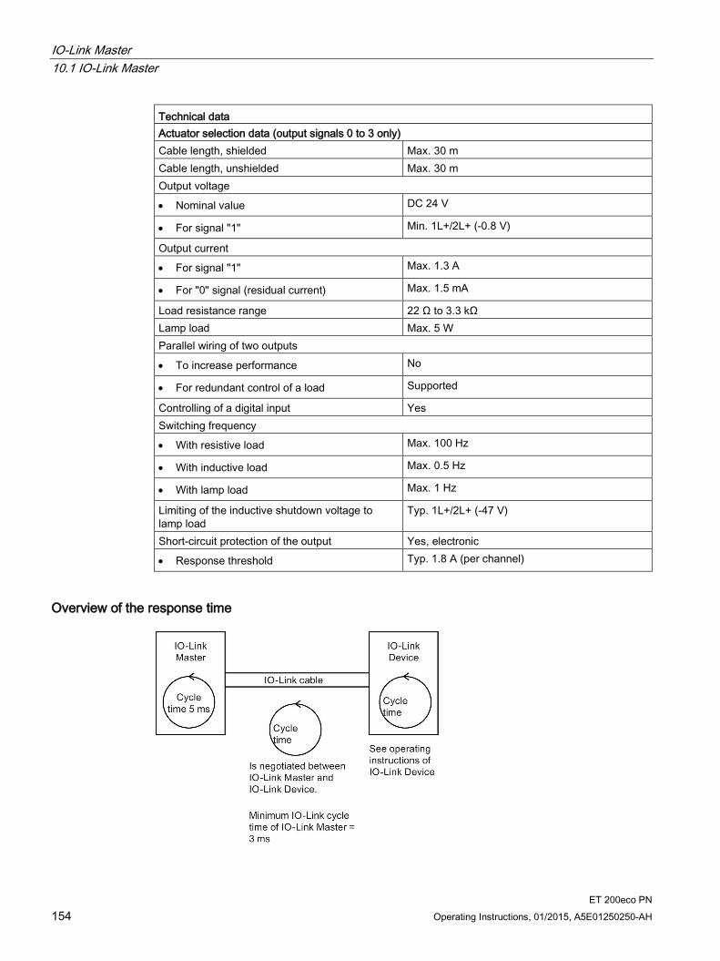
IO-Link Master 10.1 IO-Link Master
ET 200eco PN 154 Operating Instructions, 01/2015, A5E01250250-AH
Technical data Actuator selection data (output signals 0 to 3 only) Cable length, shielded Max. 30 m Cable length, unshielded Max. 30 m Output voltage
• Nominal value DC 24 V
• For signal "1" Min. 1L+/2L+ (-0.8 V)
Output current
• For signal "1" Max. 1.3 A
• For "0" signal (residual current) Max. 1.5 mA
Load resistance range 22 Ω to 3.3 kΩ Lamp load Max. 5 W Parallel wiring of two outputs
• To increase performance No
• For redundant control of a load Supported
Controlling of a digital input Yes Switching frequency
• With resistive load Max. 100 Hz
• With inductive load Max. 0.5 Hz
• With lamp load Max. 1 Hz
Limiting of the inductive shutdown voltage to lamp load
Typ. 1L+/2L+ (-47 V)
Short-circuit protection of the output Yes, electronic
• Response threshold Typ. 1.8 A (per channel)
Overview of the response time

IO-Link Master 10.2 Parameters for IO-Link Master
ET 200eco PN Operating Instructions, 01/2015, A5E01250250-AH 155
10.2 Parameters for IO-Link Master
Parameters for the IO-Link Master 4 IO-L + 8 DI + 4 DO DC 24V/1,3A 8×M12 Parameters Range of values Default setting Range of effectiveness Slot 1 "4 IO-L" Group diagnostics • Disable
• Enable
Disable Slot 1
Diagnostics enable for Ports 1 • Disable • Enable
Disable Channel
Diagnostics enable for Port 2 • Disable • Enable
Disable Channel
Diagnostics enable for Port 3 • Disable • Enable
Disable Channel
Diagnostics enable for Port 4 • Disable • Enable
Disable Channel
Slot 2 "8 DI + 4 DO DC 24V/1,3A 8×M12" Group diagnostics • Disable
• Enable
Disable Slot 2
Diagnostics: Missing 2L+ • Disable • Enable
Disable Channel group
Response to CPU/Master STOP • Shut down • Retain last value
Shut down Slot 2
Inputs Channel 4 Diagnostics: Short-circuit of
the sensor supply to M • Disable • Enable
Disable Channel group*
Diagnostics: Wire break • Disable • Enable
Disable Channel
Channel 5 Diagnostics: Short-circuit of the sensor supply to M
• Disable • Enable
Disable Channel group*
Diagnostics: Wire break • Disable • Enable
Disable Channel
Channel 6 Diagnostics: Short-circuit of the sensor supply to M
• Disable • Enable
Disable Channel group*
Diagnostics: Wire break • Disable • Enable
Disable Channel
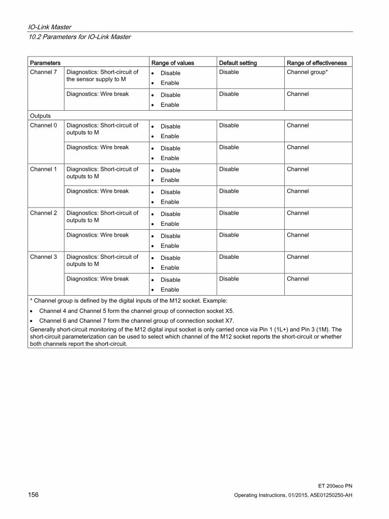
IO-Link Master 10.2 Parameters for IO-Link Master
ET 200eco PN 156 Operating Instructions, 01/2015, A5E01250250-AH
Parameters Range of values Default setting Range of effectiveness Channel 7 Diagnostics: Short-circuit of
the sensor supply to M • Disable • Enable
Disable Channel group*
Diagnostics: Wire break • Disable • Enable
Disable Channel
Outputs Channel 0 Diagnostics: Short-circuit of
outputs to M • Disable • Enable
Disable Channel
Diagnostics: Wire break • Disable • Enable
Disable Channel
Channel 1 Diagnostics: Short-circuit of outputs to M
• Disable • Enable
Disable Channel
Diagnostics: Wire break • Disable • Enable
Disable Channel
Channel 2 Diagnostics: Short-circuit of outputs to M
• Disable • Enable
Disable Channel
Diagnostics: Wire break • Disable • Enable
Disable Channel
Channel 3 Diagnostics: Short-circuit of outputs to M
• Disable • Enable
Disable Channel
Diagnostics: Wire break • Disable • Enable
Disable Channel
* Channel group is defined by the digital inputs of the M12 socket. Example: • Channel 4 and Channel 5 form the channel group of connection socket X5. • Channel 6 and Channel 7 form the channel group of connection socket X7. Generally short-circuit monitoring of the M12 digital input socket is only carried once via Pin 1 (1L+) and Pin 3 (1M). The short-circuit parameterization can be used to select which channel of the M12 socket reports the short-circuit or whether both channels report the short-circuit.
IO-Link Master 10.3 Functions
ET 200eco PN Operating Instructions, 01/2015, A5E01250250-AH 157
10.3 Functions
Introduction You can select one of the following operating modes for each of the four ports of the IO-Link Master:
IO-Link
DI
DQ
Disabled
You make the selection in the Port Configurator tool during parameterization. If no parameters have been assigned, the ports will be disabled.
Note Value status
The value status (PortQualifier) is relevant in IO-Link mode only.
Value status Each port has a value status display (PortQualifier) per device. The value status shows if the process data is valid or invalid.
By default, the value status (PortQualifier) is disabled.
IO-Link In IO-Link mode, the port is in IO-Link communication. There are two data transmission rates in this operating mode. COM1 with 4.8 kBaud; COM2 with 38.4 kBaud. The data transmission rate depends on the IO-Link Device used. The IO-Link Master and the IO-Link Device used automatically negotiate the maximum data transmission rate at startup.
DI In DI mode, a port of the IO-Link Master behaves like a standard DI.
DQ In DQ mode, a port of the IO-Link Master behaves like a standard DQ.
Disabled The respective port of the IO-Link Master is disabled in Disabled mode. The ports are disabled if the IO-Link Master has not yet been parameterized with S7-PCT (default setting).

IO-Link Master 10.3 Functions
ET 200eco PN 158 Operating Instructions, 01/2015, A5E01250250-AH
Consistency width of 8 byte The IO-Link Master has a consistency width of 8 byte. In addition to the upper limit of 32 byte input and 32 byte output for the entire IO-Link Master, there are other upper limits of 8 byte input and 8 byte output per IO-Link Device (per port).
ET 200eco PN Operating Instructions, 01/2015, A5E01250250-AH 159
I/O device analog input/analog output 11 11.1 I/O device analog input
11.1.1 I/O device 8 AI 4 U/I + 4 RTD/TC 8xM12
Order number 6ES7144-6KD00-0AB0
Properties 4 inputs for voltage and current measurement (2-wire and 4-wire transducers)
4 inputs for resistance (2-/3-/4-wire transducer), thermal resistor (2-/3-/4-conductor connection system), thermocouple or ±80 mV
Input ranges:
– ±10 V, resolution 15 bps + sign
– ±80 mV, resolution 15 bps + sign
– 0 to 10 V, resolution 15 bps
– 1 to 5 V, resolution 15 bps
– ±20 mA, resolution 15 bps + sign
– 0 to 20 mA, resolution 15 bps + sign
– 4 to 20 mA, resolution 15 bps
– 150, 300, 600, 3000 Ω, resolution 15 bps
– Ni100, Ni1000, Ni120, Ni200, Ni500, Pt100, Pt1000, Pt200, Pt500, resolution 15 bps + sign
– E, J, K, N, resolution 15 bps + sign
Dimensions 60 x 175 mm
Diagnostics
– "Missing L1+" supply voltage
– "Sensor supply short-circuit"
– "Wire break"
– "Underflow"
– "Overflow"
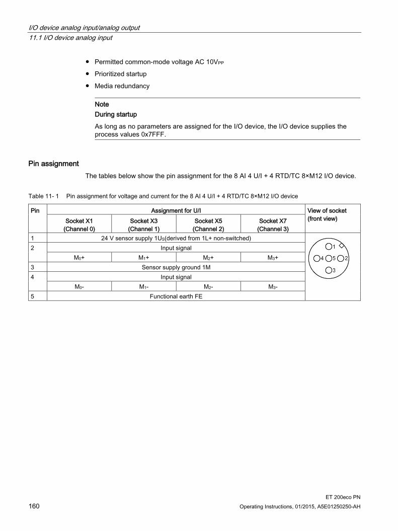
I/O device analog input/analog output 11.1 I/O device analog input
ET 200eco PN 160 Operating Instructions, 01/2015, A5E01250250-AH
Permitted common-mode voltage AC 10VPP
Prioritized startup
Media redundancy
Note
During startup
As long as no parameters are assigned for the I/O device, the I/O device supplies the process values 0x7FFF.
Pin assignment The tables below show the pin assignment for the 8 AI 4 U/I + 4 RTD/TC 8×M12 I/O device.
Table 11- 1 Pin assignment for voltage and current for the 8 AI 4 U/I + 4 RTD/TC 8×M12 I/O device
Pin Assignment for U/I View of socket (front view) Socket X1
(Channel 0) Socket X3
(Channel 1) Socket X5
(Channel 2) Socket X7
(Channel 3) 1 24 V sensor supply 1US(derived from 1L+ non-switched)
2 Input signal M0+ M1+ M2+ M3+
3 Sensor supply ground 1M 4 Input signal
M0- M1- M2- M3- 5 Functional earth FE
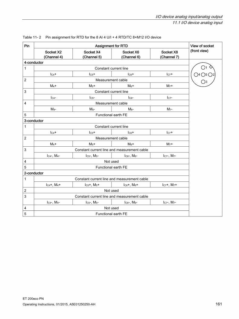
I/O device analog input/analog output 11.1 I/O device analog input
ET 200eco PN Operating Instructions, 01/2015, A5E01250250-AH 161
Table 11- 2 Pin assignment for RTD for the 8 AI 4 U/I + 4 RTD/TC 8×M12 I/O device
Pin Assignment for RTD View of socket (front view) Socket X2
(Channel 4) Socket X4
(Channel 5) Socket X6
(Channel 6) Socket X8
(Channel 7) 4-conductor
1 Constant current line IC4+ IC5+ IC6+ IC7+
2 Measurement cable M4+ M5+ M6+ M7+
3 Constant current line IC4- IC5- IC6- IC7-
4 Measurement cable M4- M5- M6- M7-
5 Functional earth FE 3-conductor 1 Constant current line
IC4+ IC5+ IC6+ IC7+ 2 Measurement cable
M4+ M5+ M6+ M7+ 3 Constant current line and measurement cable
IC4-, M4- IC5-, M5- IC6-, M6- IC7-, M7- 4 Not used 5 Functional earth FE 2-conductor 1 Constant current line and measurement cable
IC4+, M4+ IC5+, M5+ IC6+, M6+ IC7+, M7+ 2 Not used 3 Constant current line and measurement cable
IC4-, M4- IC5-, M5- IC6-, M6- IC7-, M7- 4 Not used 5 Functional earth FE
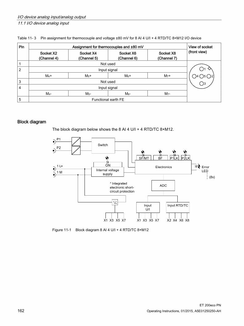
I/O device analog input/analog output 11.1 I/O device analog input
ET 200eco PN 162 Operating Instructions, 01/2015, A5E01250250-AH
Table 11- 3 Pin assignment for thermocouple and voltage ±80 mV for 8 AI 4 U/I + 4 RTD/TC 8×M12 I/O device
Pin Assignment for thermocouples and ±80 mV View of socket (front view) Socket X2
(Channel 4) Socket X4
(Channel 5) Socket X6
(Channel 6) Socket X8
(Channel 7) 1 Not used
2 Input signal M4+ M5+ M6+ M7+
3 Not used 4 Input signal
M4- M5- M6- M7- 5 Functional earth FE
Block diagram The block diagram below shows the 8 AI 4 U/I + 4 RTD/TC 8×M12.
Figure 11-1 Block diagram 8 AI 4 U/I + 4 RTD/TC 8×M12

I/O device analog input/analog output 11.1 I/O device analog input
ET 200eco PN Operating Instructions, 01/2015, A5E01250250-AH 163
Technical data Technical data Dimensions and weight Dimensions W x H x D (mm) 60 x 175 x 49 Weight Approx. 930 g Module-specific data Transmission rate 100 Mbps full duplex Transmission mode 100BASE-TX Autonegotiation Yes Bus protocol PROFINET IO
• IRT with the option "high flexibility" • IRT with the option "high performance"
Supported Ethernet services PROFINET IO (Device) • ping • arp • LLDP • Network diagnostics (SNMP) • DCP • Prioritized startup • Media redundancy
PROFINET interface
• Connection socket 2 x M12 d-coded
• Switch function Yes, internal
• Auto-crossover Yes; if autonegotiation is enabled
Manufacturer ID (Vendor ID) 002AH Device ID (DeviceID) 0306H Voltages and currents Supply voltage 1L+ DC 24 V Reverse polarity protection Yes; against destruction
• Infeed current 1L+ Max. 4 A
Supply voltage 2L+ DC 24 V
• Infeed current 2L+ Max. 4 A
Current consumption
• From supply voltage 1L+ Typ. 110 mA
• From supply voltage 2L+ 0 mA
Power loss of the device Typ. 2.8 W, without sensor current Analog inputs Number of inputs 8 (4 for U or I, 4 for RTD or thermocouple) Cable length, shielded Max. 30 m

I/O device analog input/analog output 11.1 I/O device analog input
ET 200eco PN 164 Operating Instructions, 01/2015, A5E01250250-AH
Technical data Sensor supply Number of sensor supplies 4 Total current Max. 1 A Short-circuit protection Yes; electronic, for each module, to ground
• Response threshold Min. 1.4 A
Sensor selection data Input ranges (Rated value)/input resistance or input voltage
• Voltage ±80 mV/10 MΩ ±10 V/100 kΩ 0 to 10 V/100 kΩ 1 to 5 V/100 kΩ
• Current ±20 mA/17 V for 2-wire transducer, 3.5 V for 4-wire transducer 0 to 20 mA/17 V for 2-wire transducer, 3.5 V for 4-wire transducer 4 to 20 mA/17 V for 2-wire transducer, 3.5 V for 4-wire transducer
• Resistor and thermal resistor 150 Ω/10 MΩ 300 Ω/10 MΩ 600 Ω/10 MΩ 3000 Ω/10 MΩ Ni100/10 MΩ Ni1000/10 MΩ Ni120/10 MΩ Ni200/10 MΩ Ni500/10 MΩ Pt100/10 MΩ Pt1000/10 MΩ Pt200/10 MΩ Pt500/10 MΩ
• Thermocouple Types E, J, K, N
Permitted input voltage for voltage input (destruction limit)
28.8 V continuous, 35 V for max. duration of 500 ms
Connection of sensors for voltage measurement Yes Connection of sensors for current measurement Yes (as 2-wire/4-wire transducer) Connection of sensors for RTD Yes (with 2-/3-/4-conductor connection) Connection of sensors for thermocouples Yes Temperature compensation for thermocouples 1
• Internal temperature compensation Yes, parameterizable
• External temperature compensation Yes, parameterizable
Technical unit for temperature measurement °C, °F, K Formation of analog values Measuring principle Integrating
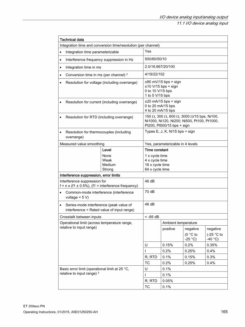
I/O device analog input/analog output 11.1 I/O device analog input
ET 200eco PN Operating Instructions, 01/2015, A5E01250250-AH 165
Technical data Integration time and conversion time/resolution (per channel)
• Integration time parameterizable Yes
• Interference frequency suppression in Hz 500/60/50/10
• Integration time in ms 2.0/16.667/20/100
• Conversion time in ms (per channel) 2 4/19/22/102
• Resolution for voltage (including overrange) ±80 mV/15 bps + sign ±10 V/15 bps + sign 0 to 10 V/15 bps 1 to 5 V/15 bps
• Resolution for current (including overrange) ±20 mA/15 bps + sign 0 to 20 mA/15 bps 4 to 20 mA/15 bps
• Resolution for RTD (including overrange) 150 Ω, 300 Ω, 600 Ω, 3000 Ω/15 bps, Ni100, Ni1000, Ni120, Ni200; Ni500, Pt100, Pt1000, Pt200, Pt500/15 bps + sign
• Resolution for thermocouples (including overrange)
Types E, J, K, N/15 bps + sign
Measured value smoothing Yes, parameterizable in 4 levels Level
None Weak Medium Strong
Time constant 1 x cycle time 4 x cycle time 16 x cycle time 64 x cycle time
Interference suppression, error limits Interference suppression for f = n x (f1 ± 0.5%), (f1 = interference frequency)
46 dB
• Common-mode interference (interference voltage < 5 V)
70 dB
• Series-mode interference (peak value of interference < Rated value of input range)
46 dB
Crosstalk between inputs < -85 dB Operational limit (across temperature range, relative to input range)
Ambient temperature positive negative
(0 °C to -25 °C)
negative (-25 °C to -40 °C)
U 0.15% 0.2% 0.35% I 0.2% 0.25% 0.4% R, RTD 0.1% 0.15% 0.3% TC 0.2% 0.25% 0.4%
Basic error limit (operational limit at 25 °C, relative to input range) 3
U 0.1% I 0.1% R, RTD 0.05% TC 0.1%
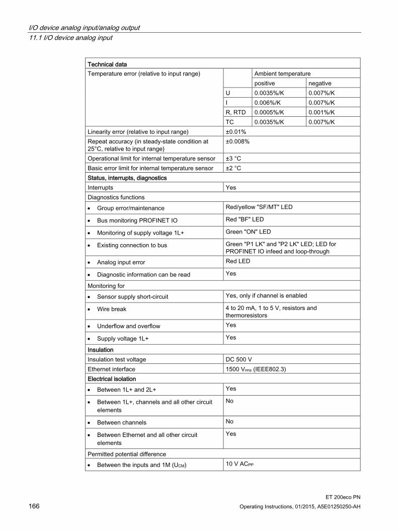
I/O device analog input/analog output 11.1 I/O device analog input
ET 200eco PN 166 Operating Instructions, 01/2015, A5E01250250-AH
Technical data Temperature error (relative to input range) Ambient temperature
positive negative U 0.0035%/K 0.007%/K I 0.006%/K 0.007%/K R, RTD 0.0005%/K 0.001%/K TC 0.0035%/K 0.007%/K
Linearity error (relative to input range) ±0.01% Repeat accuracy (in steady-state condition at 25°C, relative to input range)
±0.008%
Operational limit for internal temperature sensor ±3 °C Basic error limit for internal temperature sensor ±2 °C Status, interrupts, diagnostics Interrupts Yes Diagnostics functions
• Group error/maintenance Red/yellow "SF/MT" LED
• Bus monitoring PROFINET IO Red "BF" LED
• Monitoring of supply voltage 1L+ Green "ON" LED
• Existing connection to bus Green "P1 LK" and "P2 LK" LED; LED for PROFINET IO infeed and loop-through
• Analog input error Red LED
• Diagnostic information can be read Yes
Monitoring for
• Sensor supply short-circuit Yes, only if channel is enabled
• Wire break 4 to 20 mA, 1 to 5 V, resistors and thermoresistors
• Underflow and overflow Yes
• Supply voltage 1L+ Yes
Insulation Insulation test voltage DC 500 V Ethernet interface 1500 Vrms (IEEE802.3) Electrical isolation
• Between 1L+ and 2L+ Yes
• Between 1L+, channels and all other circuit elements
No
• Between channels No
• Between Ethernet and all other circuit elements
Yes
Permitted potential difference
• Between the inputs and 1M (UCM) 10 V ACPP
I/O device analog input/analog output 11.1 I/O device analog input
ET 200eco PN Operating Instructions, 01/2015, A5E01250250-AH 167
Technical data 1 "No temperature compensation" is always run when using the measuring type ±80 mV regardless of the configured temperature compensation. 2 With 3-wire resistance measurement (and thermal resistor) the measuring resistances and the line resistances are updated in alternating cycles. Rapid changes in the measuring resistance therefore impair the accuracy. 3 For thermocouples, the information refers to the temperature range from -100 °C to nominal value
Note
The accuracy information is valid for static thermal states and changes in ambient temperature < 1 K/h.
The I/O device achieves the highest accuracy with the 4-wire connection system (see technical specifications above).
Although the 3-wire connection system compensates for the missing wire, the accuracy is impaired. With the 2-wire connection system, the line resistances considerably impair the accuracy.
In the last two cases this impairment is not determinable.
Note
With the 3-wire connection system, the compensation of the missing cable is only ensured if all three cores in the cable have the same length and cross-section.
See also Response times for analog input device and output device (Page 241)

I/O device analog input/analog output 11.1 I/O device analog input
ET 200eco PN 168 Operating Instructions, 01/2015, A5E01250250-AH
11.1.2 8 AI RTD/TC 8×M12 I/O device
Order number 6ES7-144-6KD50-0AB0
Properties The electronic module 8 AI RTD/TC 8×M12 has the properties listed below:
8 freely parameterizable inputs:
– Resistance (2-/3-/4-wire transmitter)
– Thermoresistor (2-/3-/4-conductor connection system)
– Thermocouple or ±80 mV
Input ranges:
– Voltage measurement: ±80 mV; resolution 15 bits + sign
– Resistance measurement: 150 Ω, 300 Ω, 600 Ω, 3000 Ω; resolution 15 bits
– Resistance thermometer: Pt100, Ni100, Ni120, Pt200, Ni200, Pt500, Ni500, Pt1000, Ni1000; resolution 15 bits + sign
– Thermocouple elements: E, J, K, N; resolution 15 bits + sign
Dimensions 60 x 175 mm
Diagnostics
– "Missing L1+" supply voltage
– "Wire break"
– "Underflow"
– "Overflow"
Permitted common-mode voltage AC 10VPP
Prioritized startup
Media redundancy
Note
During startup
As long as no parameters are assigned for the I/O device, the I/O device supplies the process values 7FFFH.

I/O device analog input/analog output 11.1 I/O device analog input
ET 200eco PN Operating Instructions, 01/2015, A5E01250250-AH 169
Pin assignment The tables below show the pin assignment for the 8 AI RTD/TC 8xM12 electronic module.
Table 11- 4 Pin assignment for RTD for the 8 AI RTD/TC 8xM12 electronic module
Pin Assignment for RTD View of socket (front view) Socket X1
(Channel 0)
Socket X2 (Channel
4)
Socket X3 (Channel
1)
Socket X4 (Channel
5)
Socket X5 (Channel
2)
Socket X6 (Channel
6)
Socket X7 (Channel
3)
Socket X8 (Channel
7) 4-conductor
1 Constant current line IC0+ IC4+ IC1+ IC5+ IC2+ IC6+ IC3+ IC7+
2 Measurement cable M0+ M4+ M1+ M5+ M2+ M6+ M3+ M7+
3 Constant current line IC0- IC4- IC1- IC5- IC2- IC6- IC3- IC7-
4 Measurement cable M0- M4- M1- M5- M2- M6- M3- M7-
5 Functional earth FE 3-conductor 1 Constant current line
IC0+ IC4+ IC1+ IC5+ IC2+ IC6+ IC3+ IC7+ 2 Measurement cable
M0+ M4+ M1+ M5+ M2+ M6+ M3+ M7+ 3 Constant current line and measurement cable
IC0-, M0- IC4-, M4- IC1-, M1- IC5-, M5- IC2-, M2- IC6-, M6- IC3-, M3- IC7-, M7- 4 Not used 5 Functional earth FE 2-conductor 1 Constant current line and measurement cable
IC0+, M0+ IC4+, M4+ IC1+, M1+ IC5+, M5+ IC2+, M2+ IC6+, M6+ IC3+, M3+ IC7+, M7+ 2 Not used 3 Constant current line and measurement cable
IC0-, M0- IC4-, M4- IC1-, M1- IC5-, M5- IC2-, M2- IC6-, M6- IC3-, M3- IC7-, M7- 4 Not used 5 Functional earth FE
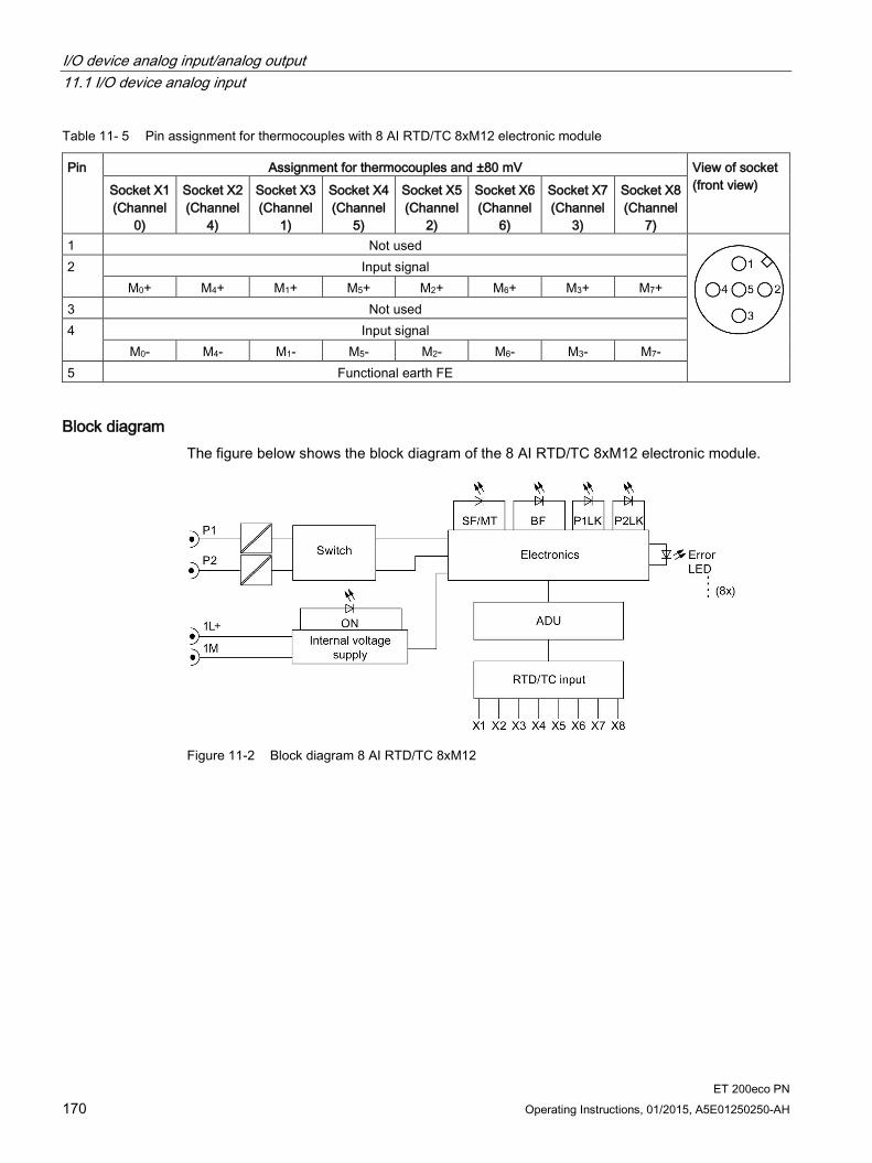
I/O device analog input/analog output 11.1 I/O device analog input
ET 200eco PN 170 Operating Instructions, 01/2015, A5E01250250-AH
Table 11- 5 Pin assignment for thermocouples with 8 AI RTD/TC 8xM12 electronic module
Pin Assignment for thermocouples and ±80 mV View of socket (front view) Socket X1
(Channel 0)
Socket X2 (Channel
4)
Socket X3 (Channel
1)
Socket X4 (Channel
5)
Socket X5 (Channel
2)
Socket X6 (Channel
6)
Socket X7 (Channel
3)
Socket X8 (Channel
7) 1 Not used
2 Input signal M0+ M4+ M1+ M5+ M2+ M6+ M3+ M7+
3 Not used 4 Input signal
M0- M4- M1- M5- M2- M6- M3- M7- 5 Functional earth FE
Block diagram The figure below shows the block diagram of the 8 AI RTD/TC 8xM12 electronic module.
Figure 11-2 Block diagram 8 AI RTD/TC 8xM12

I/O device analog input/analog output 11.1 I/O device analog input
ET 200eco PN Operating Instructions, 01/2015, A5E01250250-AH 171
Technical data Technical data Dimensions and weight Dimensions W x H x D (mm) 60 x 175 x 49 Weight Approx. 930 g Module-specific data Transmission rate 100 Mbps full duplex Transmission mode 100 BASE-TX Autonegotiation Yes Bus protocol PROFINET IO
• IRT with the option "high flexibility" • IRT with the option "high performance"
Supported Ethernet services PROFINET IO (Device) • ping • arp • LLDP • Network diagnostics (SNMP) • DCP • Prioritized startup • Media redundancy
PROFINET interface
• Connection socket 2 x M12 d-coded
• Switch function Yes, internal
• Auto-crossover Yes; if autonegotiation is enabled
Manufacturer ID (Vendor ID) 002AH Device ID (DeviceID) 0306H Voltages and currents Supply voltage 1L+ DC 24 V Reverse polarity protection Yes; against destruction
• Infeed current 1L+ Max. 4 A
Supply voltage 2L+ DC 24 V
• Infeed current 2L+ Max. 4 A
Current consumption
• From supply voltage 1L+ Typ. 110 mA
• From supply voltage 2L+ 0 mA
Power loss of the device Typ. 2.8 W, without sensor current Analog inputs Number of inputs 8, for RTD or thermocouple Cable length, shielded Max. 30 m
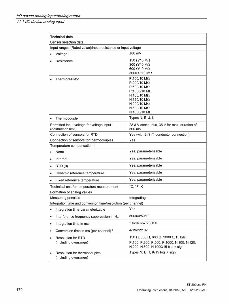
I/O device analog input/analog output 11.1 I/O device analog input
ET 200eco PN 172 Operating Instructions, 01/2015, A5E01250250-AH
Technical data Sensor selection data Input ranges (Rated value)/input resistance or input voltage
• Voltage ±80 mV
• Resistance 150 Ω/10 MΩ 300 Ω/10 MΩ 600 Ω/10 MΩ 3000 Ω/10 MΩ
• Thermoresistor Pt100/10 MΩ Pt200/10 MΩ Pt500/10 MΩ Pt1000/10 MΩ Ni100/10 MΩ Ni120/10 MΩ Ni200/10 MΩ Ni500/10 MΩ Ni1000/10 MΩ
• Thermocouple Types N, E, J, K
Permitted input voltage for voltage input (destruction limit)
28.8 V continuous, 35 V for max. duration of 500 ms
Connection of sensors for RTD Yes (with 2-/3-/4-conductor connection) Connection of sensors for thermocouples Yes Temperature compensation 1
• None Yes, parameterizable
• Internal Yes, parameterizable
• RTD (0) Yes, parameterizable
• Dynamic reference temperature Yes, parameterizable
• Fixed reference temperature Yes, parameterizable
Technical unit for temperature measurement °C, °F, K Formation of analog values Measuring principle Integrating Integration time and conversion time/resolution (per channel)
• Integration time parameterizable Yes
• Interference frequency suppression in Hz 500/60/50/10
• Integration time in ms 2.0/16.667/20/100
• Conversion time in ms (per channel) 2 4/19/22/102
• Resolution for RTD (including overrange)
150 Ω, 300 Ω, 600 Ω, 3000 Ω/15 bits Pt100, Pt200, Pt500, Pt1000, Ni100, Ni120, Ni200, Ni500, Ni1000/15 bits + sign
• Resolution for thermocouples (including overrange)
Types N, E, J, K/15 bits + sign
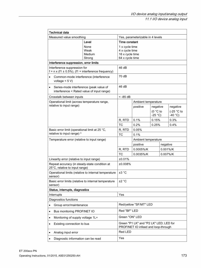
I/O device analog input/analog output 11.1 I/O device analog input
ET 200eco PN Operating Instructions, 01/2015, A5E01250250-AH 173
Technical data Measured value smoothing Yes, parameterizable in 4 levels Level
None Weak Medium Strong
Time constant 1 x cycle time 4 x cycle time 16 x cycle time 64 x cycle time
Interference suppression, error limits Interference suppression for f = n x (f1 ± 0.5%), (f1 = interference frequency)
46 dB
• Common-mode interference (interference voltage < 5 V)
70 dB
• Series-mode interference (peak value of interference < Rated value of input range)
46 dB
Crosstalk between inputs < -85 dB Operational limit (across temperature range, relative to input range)
Ambient temperature positive negative
(0 °C to -25 °C)
negative (-25 °C to -40 °C)
R, RTD 0.1% 0.15% 0.3% TC 0.2% 0.25% 0.4%
Basic error limit (operational limit at 25 °C, relative to input range) 3
R, RTD 0.05% TC 0.1%
Temperature error (relative to input range) Ambient temperature positive negative
R, RTD 0.0005%/K 0.001%/K TC 0.0035%/K 0.007%/K
Linearity error (relative to input range) ±0.01% Repeat accuracy (in steady-state condition at 25°C, relative to input range)
±0.008%
Operational limits (relative to internal temperature sensor)
±3 °C
Basic error limits (relative to internal temperature sensor)
±2 °C
Status, interrupts, diagnostics Interrupts Yes Diagnostics functions
• Group error/maintenance Red/yellow "SF/MT" LED
• Bus monitoring PROFINET IO Red "BF" LED
• Monitoring of supply voltage 1L+ Green "ON" LED
• Existing connection to bus Green "P1 LK" and "P2 LK" LED; LED for PROFINET IO infeed and loop-through
• Analog input error Red LED
• Diagnostic information can be read Yes
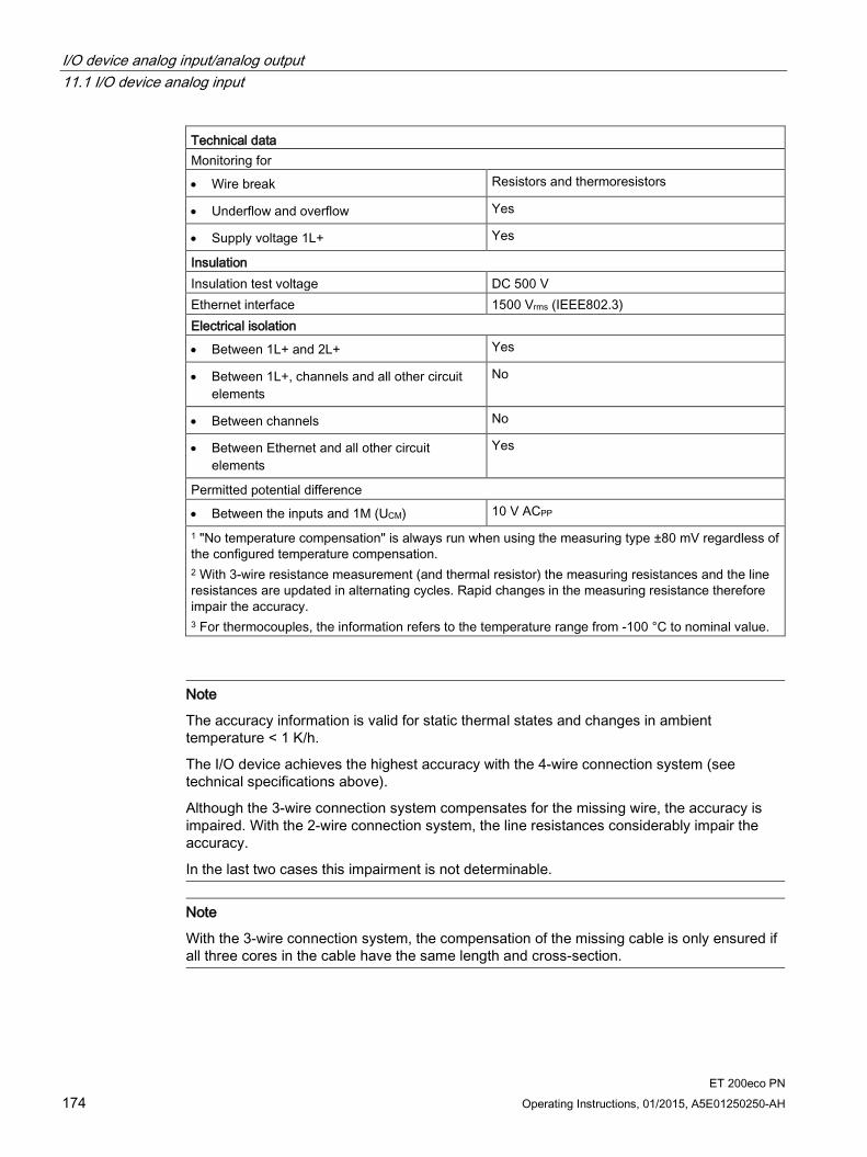
I/O device analog input/analog output 11.1 I/O device analog input
ET 200eco PN 174 Operating Instructions, 01/2015, A5E01250250-AH
Technical data Monitoring for
• Wire break Resistors and thermoresistors
• Underflow and overflow Yes
• Supply voltage 1L+ Yes
Insulation Insulation test voltage DC 500 V Ethernet interface 1500 Vrms (IEEE802.3) Electrical isolation
• Between 1L+ and 2L+ Yes
• Between 1L+, channels and all other circuit elements
No
• Between channels No
• Between Ethernet and all other circuit elements
Yes
Permitted potential difference
• Between the inputs and 1M (UCM) 10 V ACPP
1 "No temperature compensation" is always run when using the measuring type ±80 mV regardless of the configured temperature compensation. 2 With 3-wire resistance measurement (and thermal resistor) the measuring resistances and the line resistances are updated in alternating cycles. Rapid changes in the measuring resistance therefore impair the accuracy. 3 For thermocouples, the information refers to the temperature range from -100 °C to nominal value.
Note
The accuracy information is valid for static thermal states and changes in ambient temperature < 1 K/h.
The I/O device achieves the highest accuracy with the 4-wire connection system (see technical specifications above).
Although the 3-wire connection system compensates for the missing wire, the accuracy is impaired. With the 2-wire connection system, the line resistances considerably impair the accuracy.
In the last two cases this impairment is not determinable.
Note
With the 3-wire connection system, the compensation of the missing cable is only ensured if all three cores in the cable have the same length and cross-section.

I/O device analog input/analog output 11.1 I/O device analog input
ET 200eco PN Operating Instructions, 01/2015, A5E01250250-AH 175
11.1.3 Parameter overview analog input
Parameters for analog input 8 AI 4 U/I + 4 RTD/TC 8xM12 (6ES7144-6KD00-0AB0) Parameters Range of values Default setting Range of effectiveness Group diagnostics • Disable
• Enable
Disable Device
Diagnostics, missing 1L+ • Disable • Enable
Disable Device
Diagnostics, sensor supply short-circuit
• Disable • Enable
Disable Device
Interference frequency suppression
• OFF • 60 Hz • 50 Hz • 10 Hz
50 Hz Device
Temperature unit • Celsius • Fahrenheit • Kelvin
Celsius Channel groups 4 to 7
Reference temperature for TC • -145.0 to 155.0 (Celsius) • -229.0 to 311.0 (Fahrenheit) • 128.2 to 428.2 (Kelvin)
0.0 Device
Measurement type, channels 0 to 3
• Disabled • Voltage • Current (4-wire transducer) • Current (2-wire transducer)
Voltage Channel
Measurement type, channels 4 to 7
• Disabled • Resistance (4-wire connection) • Resistance (3-wire connection) • Resistance (2-wire connection) • Thermoresistor
(linear, 4-conductor connection) • Thermoresistor
(linear, 3-conductor connection) • Thermoresistor
(linear, 2-conductor connection) • Thermocouple elements • Voltage +/-80 mV
Thermoresistor Pt100 (4-conductor connection)
Channel

I/O device analog input/analog output 11.1 I/O device analog input
ET 200eco PN 176 Operating Instructions, 01/2015, A5E01250250-AH
Parameters Range of values Default setting Range of effectiveness Measurement range, channels 0 to 3
• 1 to 5 V • 0 to 10 V • +/-10 V • 0 to 20 mA • 4 to 20 mA • ±20 mA
±10 V Channel
Measuring range, channels 4 to 7
• +/-80 mV • 150 Ω • 300 Ω • 600 Ω • 3000 Ω • Pt100 Climatic range • Pt100 Standard range • Pt200 Climatic range • Pt200 Standard range • Pt500 Climatic range • Pt500 Standard range • Pt1000 Climatic range • Pt1000 Standard range • Ni100 Climatic range • Ni100 Standard range • Ni120 Climatic range • Ni120 Standard range • Ni200 Climatic range • Ni200 Standard range • Ni500 Climatic range • Ni500 Standard range • Ni1000 Climatic range • Ni1000 Standard range • TC_EL Typ_N_[NiCrSi_NiSi] • TC_EL Typ_E_[NiCr_CuNi] • TC_EL Typ_J_[Fe_CuNi] • TC_EL Typ_K_[NiCr_Ni]
Pt100 Standard range Channel
Reference junction for thermoresistor (TC)
• Internal • External
Internal Channel

I/O device analog input/analog output 11.1 I/O device analog input
ET 200eco PN Operating Instructions, 01/2015, A5E01250250-AH 177
Parameters Range of values Default setting Range of effectiveness Temperature coefficient • Pt 0.003916
• Pt 0.003902 • Pt 0.00392 • Pt 0.0038511 • Ni 0.00618 • Ni 0.00672 • Ni 0.005000
Pt 0.0038511 Channel
Smoothing • None • Weak • Medium • Strong
None Channel
Diagnostics, wire break • Disable • Enable
Disable Channel
Diagnostics, underflow • Disable • Enable
Disable Channel
Diagnostics, overflow • Disable • Enable
Disable Channel
1This value can also be shown as α = 0.00385055 in the parameter assignment.

I/O device analog input/analog output 11.1 I/O device analog input
ET 200eco PN 178 Operating Instructions, 01/2015, A5E01250250-AH
Parameters for analog input 8 AI RTD/TC 8xM12 (6ES7144-6KD50-0AB0) Parameters Range of values Default setting Range of effectiveness Group diagnostics • Disable
• Enable
Disable Device
Diagnostics, missing 1L+ • Disable • Enable
Disable Device
Interference frequency sup-pression
• OFF • 60 Hz • 50 Hz • 10 Hz
50 Hz Device
Temperature unit • Celsius • Fahrenheit • Kelvin
Celsius Device
Reference temperature for TC • -145.0 to 155.0 (Celsius) • -229.0 to 311.0 (Fahrenheit) • 128.2 to 428.2 (Kelvin)
0.0 Device
Measurement type, channels 0 to 7
• Disabled • Voltage +/-80 mV • Resistance (4-wire connection) • Resistance (3-wire connection) • Resistance (2-wire connection) • Thermoresistor
(linear, 4-conductor connection) • Thermoresistor
(linear, 3-conductor connection) • Thermoresistor
(linear, 2-conductor connection) • Thermocouple elements
Thermoresistor Pt100 (4-conductor connection)
Channel
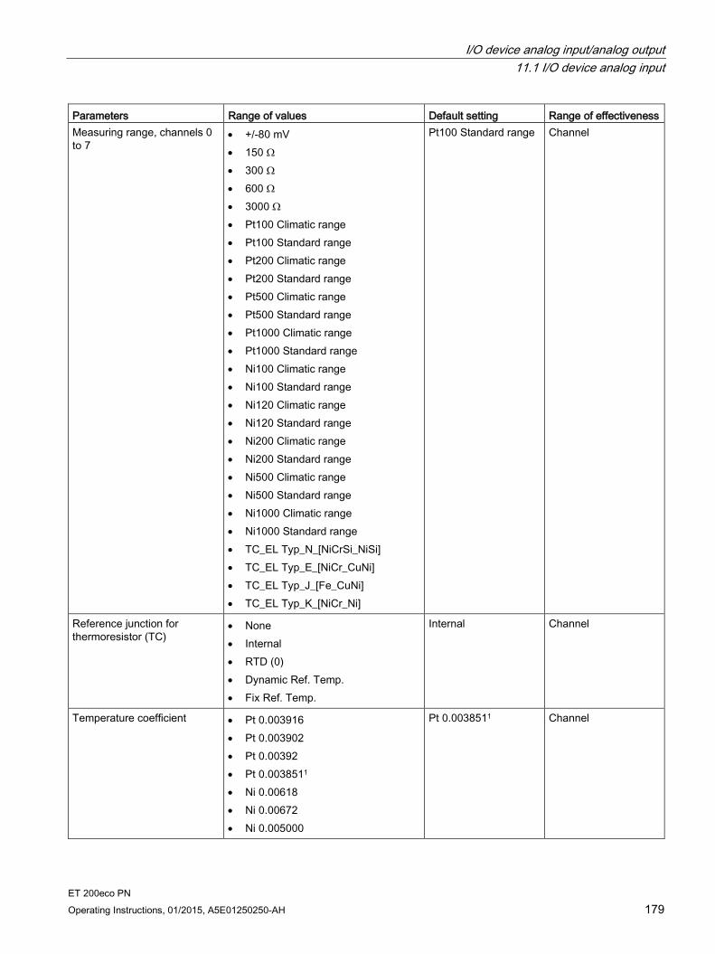
I/O device analog input/analog output 11.1 I/O device analog input
ET 200eco PN Operating Instructions, 01/2015, A5E01250250-AH 179
Parameters Range of values Default setting Range of effectiveness Measuring range, channels 0 to 7
• +/-80 mV • 150 Ω • 300 Ω • 600 Ω • 3000 Ω • Pt100 Climatic range • Pt100 Standard range • Pt200 Climatic range • Pt200 Standard range • Pt500 Climatic range • Pt500 Standard range • Pt1000 Climatic range • Pt1000 Standard range • Ni100 Climatic range • Ni100 Standard range • Ni120 Climatic range • Ni120 Standard range • Ni200 Climatic range • Ni200 Standard range • Ni500 Climatic range • Ni500 Standard range • Ni1000 Climatic range • Ni1000 Standard range • TC_EL Typ_N_[NiCrSi_NiSi] • TC_EL Typ_E_[NiCr_CuNi] • TC_EL Typ_J_[Fe_CuNi] • TC_EL Typ_K_[NiCr_Ni]
Pt100 Standard range Channel
Reference junction for thermoresistor (TC)
• None • Internal • RTD (0) • Dynamic Ref. Temp. • Fix Ref. Temp.
Internal Channel
Temperature coefficient • Pt 0.003916 • Pt 0.003902 • Pt 0.00392 • Pt 0.0038511 • Ni 0.00618 • Ni 0.00672 • Ni 0.005000
Pt 0.0038511 Channel

I/O device analog input/analog output 11.1 I/O device analog input
ET 200eco PN 180 Operating Instructions, 01/2015, A5E01250250-AH
Parameters Range of values Default setting Range of effectiveness Smoothing • None
• Weak • Medium • Strong
None Channel
Diagnostics, wire break • Disable • Enable
Disable Channel
Diagnostics, underflow • Disable • Enable
Disable Channel
Diagnostics, overflow • Disable • Enable
Disable Channel
1This value can also be shown as α = 0.00385055 in the parameter assignment.
Measuring type with 8 AI RTD The following table lists the temperature coefficients and measuring ranges you can assign for each measurement type:
Measurement type Temperature coefficient Measuring range Thermoresistor 4-conductor Thermoresistor 3-conductor Thermoresistor 2-conductor
Pt 0.0038511, 2/ Pt 0.003916/ Pt 0.003902/ Pt 0.003920
Pt100 Climatic range / Pt100 Standard range / Pt200 Climatic range / Pt200 Standard range / Pt500 Climatic range / Pt500 Standard range / Pt1000 Climatic range / Pt1000 Standard range
Ni 0.0061801/ Ni 0.006720/ Ni 0.0053
Ni100 Climatic range / Ni100 Standard range / Ni120 Climatic range / Ni120 Standard range / Ni200 Climatic range / Ni200 Standard range / Ni500 Climatic range / Ni500 Standard range / Ni1000 Climatic range / Ni1000 Standard range
1 The default settings for the temperature coefficients apply according to the standard EN60751. 2This value can also be shown as α = 0.00385055 in the parameter assignment. 3 The thermoresistor LG-Ni1000 corresponds to the thermoresistor Ni1000 with the temperature coefficient 0.005
Note
For a thermoresistor, the climatic type is only possible with temperature units Celsius (°C) and Fahrenheit (°F).
I/O device analog input/analog output 11.1 I/O device analog input
ET 200eco PN Operating Instructions, 01/2015, A5E01250250-AH 181
11.1.4 Parameter description analog input
Group diagnostics You can generally enable and disable the diagnostics function of the device with this parameter.
The "Fault" and "Parameter assignment error" diagnostics functions are always independent of the group diagnostics.
Diagnostics: Missing 1L+ If you enable this parameter, the check for missing supply voltage is enabled.
Diagnostics: Short-circuit sensor supply If you enable this parameter, a diagnostics event is generated if a short-circuit of the sensor supply to ground is detected and the channel is enabled. The sensor supply is monitored for connectors X1, X3, X5, and X7. No differentiation is made as to the connector where the sensor short-circuit occurred.
Interference frequency suppression With this parameter, you set the integration time of the device, based on the selected interference frequency. Select the frequency of the supply voltage used. Interference frequency suppression "Off" means 500 Hz, which corresponds to an integration time of 2 ms for a measurement channel.
Temperature unit This parameter is used to select the unit in which the temperature is detected.
Reference temperature for TC The reference temperature applies for all channels at which "Reference junction" "Fix Ref. Temp." was selected. Information about the value range of the reference temperature is available in the table Reference temperature for TC (Page 198).
I/O device analog input/analog output 11.1 I/O device analog input
ET 200eco PN 182 Operating Instructions, 01/2015, A5E01250250-AH
Measurement type (channel-wise) Click the field to have the available measurement types displayed and select them.
Possible measurement types:
Voltage ±80 mV
Resistor (4-wire connection)
Resistor (3-wire connection)
Resistor (2-wire connection)
Thermal resistor (linear, 4-wire connection)
Thermal resistor (linear, 3-wire connection)
Thermal resistor (linear, 2-wire connection)
Thermocouple
With this parameter, you set the measurement type, for example, voltage. For any unused channels, you must select the disabled setting. For a disabled channel, the conversion time and integration time of the channel = 0 s, and the overall cycle time of the device is reduced.
Measuring range With this parameter, you set the measuring range of the selected measurement type.
Temperature coefficient (for RTD, thermoresistor) The correction factor for the temperature coefficient (α-value) specifies the extent to which the resistance of a certain material changes when the temperature is raised by 1 °C.
The α-values conform to EN 60751, GOST 6651, JIS C 1604, and ASTM E-1137.
The temperature coefficient depends on the chemical composition of the material.
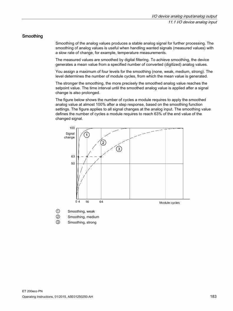
I/O device analog input/analog output 11.1 I/O device analog input
ET 200eco PN Operating Instructions, 01/2015, A5E01250250-AH 183
Smoothing Smoothing of the analog values produces a stable analog signal for further processing. The smoothing of analog values is useful when handling wanted signals (measured values) with a slow rate of change, for example, temperature measurements.
The measured values are smoothed by digital filtering. To achieve smoothing, the device generates a mean value from a specified number of converted (digitized) analog values.
You assign a maximum of four levels for the smoothing (none, weak, medium, strong). The level determines the number of module cycles, from which the mean value is generated.
The stronger the smoothing, the more precisely the smoothed analog value reaches the setpoint value. The time interval until the smoothed analog value is applied after a signal change is also prolonged.
The figure below shows the number of cycles a module requires to apply the smoothed analog value at almost 100% after a step response, based on the smoothing function settings. The figure applies to all signal changes at the analog input. The smoothing value defines the number of cycles a module requires to reach 63% of the end value of the changed signal.
① Smoothing, weak ② Smoothing, medium ③ Smoothing, strong
I/O device analog input/analog output 11.1 I/O device analog input
ET 200eco PN 184 Operating Instructions, 01/2015, A5E01250250-AH
Diagnostics: Wire break When this parameter is enabled, the Wire break diagnostics event is generated when a wire break is detected.
Observe the rules outlined below to handle a wire break in the 1 V to 5 V and 4 mA to 20 mA measuring ranges: Parameters Event Measured
value Explanation
Enable wire break1 Wire break 7FFFH Diagnostics, wire break Wire break disabled1
Underflow enabled
Wire break 8000H Measured value after leaving the undershoot range Diagnostic message Lower limit value undershot
Wire break disabled1
Underflow disabled Wire break 8000H Measured value after leaving the undershoot
range 1 Measuring range limits for wire break detection and measuring range undershoot detection: • 1 V to 5 V: At 0.296 V • 4 mA to 20 mA: At 1.185 mA
Diagnostics at 8AI RTD/TC Take the following diagnostics into account: Diagnostics, wire break
Diagnostics, overflow
Diagnostics, underflow
Event Process data
Diagnostic message per channel
Activated Deactivated Deactivated Wire break 0x7FFF Wire break Deactivated Deactivated Activated Wire break 0x8000 Low limit violated Deactivated Activated Deactivated Wire break 0x7FFF High limit violated Deactivated Activated Activated Wire break 0x8000 Low limit violated Deactivated Deactivated Deactivated Wire break 0x7FFF
Diagnostics: Underflow If the measured value reaches the underflow range and you enable this parameter, the Underflow diagnostics event is generated.
Diagnostics: Overflow If the measured value reaches the overflow range and you enable this parameter, the Overflow diagnostics event is generated.
I/O device analog input/analog output 11.1 I/O device analog input
ET 200eco PN Operating Instructions, 01/2015, A5E01250250-AH 185
Reference junction for thermoresistor (TC) A difference in temperature between the measuring point and the free ends of the thermocouple (terminal point) generates a voltage between the free ends, namely the thermoelectric voltage. The value of this thermoelectric voltage is determined by the temperature difference between the measuring point and the free ends, and by the type of material combination of the thermocouple. Since a thermocouple always measures a temperature difference, the free ends at the reference junction must be maintained at a known temperature in order to determine the temperature of the measuring point.
In the case of the I/O device 8 AI 4 U/I + 4 RTD/TC 8×M12 and 8 AI RTD/TC 8xM12, the following compensation settings are possible:
No / external compensation: The reference junction temperature is measured outside the module, e.g., via a compensation slot.
With this compensation type, the reference junction temperature of the thermocouples is measured outside the two I/O devices. For this purpose you can, for example, connect a compensation slot to the thermocouple.
With this compensation type, the temperature of the reference junction is specified at 0 °C .
The temperature of 0 °C is reached when a compensation slot is used. One compensation slot is required per thermocouple.
Internal: The temperature of the measuring point is measured in the housing of the I/O device.
With this type of compensation the reference junction temperature is determined with an internal temperature sensor. One temperature sensor is integrated into each I/O device.
The reference junction temperature is detected by an internal temperature sensor.
The same reference junction temperature is assigned to all the channels of the I/O devices that you selected for this type of compensation.
I/O device analog input/analog output 11.1 I/O device analog input
ET 200eco PN 186 Operating Instructions, 01/2015, A5E01250250-AH
With the I/O device 8 AI RTD/TC 8xM12, the following compensation settings are also possible :
RTD (0): The reference junction temperature is determined by means of a thermal resistor (Pt1000).
With this compensation the reference junction temperature is determined by measuring the resistance value of a Pt1000 at the terminal point of the M12 compensation connector. The resistance measurement may only be carried out on the round socket X1 (Channel 0).
The reference junction temperature is determined by the resistance value Pt1000.
The same reference junction temperature is assigned to all the channels of the I/O device 8 AI RTD/TC 8xM12 that you selected for this type of compensation.
The cycle time increases by 1 x the conversion time.
If the compensation RTD (0) is selected on a channel of the I/O device 8 AI RTD/TC 8xM12, the measurement type for Channel 0 (X1) is limited; that is, only the measurement types "Thermocouple" or "±80 mV" are possible.
A wire break at Pt1000 cannot be detected and is reported with the diagnosis "Reference channel error".
The M12 compensation connector is provided for the temperature compensation "RTD (0)" (prerequisite: "Reference junction" parameter set to "RTD (0)". For all other temperature compensations, no M12 compensation connector is required.
The M12 compensation connector has an integrated resistance thermometer Pt1000 (with α = 0.003851) for compensating the reference junction temperature of the thermocouples. The α value conforms to the standards EN 60751, GOST 6651, JIS C 1604 and ASTM E-1137.
The M12 compensation connector is delivered unassembled. You can connect a thermocouple by using terminals 2 and 4 of the M12 compensation connector.
The M12 compensation connector is bolted to the round socket X1 on the connection module CM IO 4 x M12 (torque: 1.5 Nm). The procedure is identical to the M12 connector (see section Mounting (Page 19)).
Note
The M12 compensation connector is only designed for the electronic module 8 AI RTD/TC 8xM12. Operation without a cable is not permitted in order to comply with degree of protection IP67.
Dynamic Ref. Temp.: The reference junction temperature is measured via a module on a different station.
With this type of compensation the reference junction temperature (compensation voltage) is measured by means of an external module on another station.
The reference junction temperature is transferred from the CPU to the I/O device 8 AI RTD/TC 8xM12 by means of the data record DS2 using the SFB 53.
An separate reference junction temperature can be assigned by means of the the user program to each channel for which you select this type of compensation.

I/O device analog input/analog output 11.1 I/O device analog input
ET 200eco PN Operating Instructions, 01/2015, A5E01250250-AH 187
Fix Ref. Temp.: The reference temperature is specified permanently.
With this type of compensation, the reference junction temperature is stored as a parameter.
The reference junction temperature is specified in the parameter "Reference temperature for TC".
The possible value range is listed in the table Reference temperature for TC (Page 198).
The parameterized reference junction temperature is valid for all the channels of the I/O device for which you have selected this type of compensation.
11.1.5 Analog value representation for measuring ranges with SIMATIC S7
Representation of analog values With the same nominal range, the digitized analog value is the same for input and output values. Analog values are represented in two's complement.
The following table shows the representation of analog values of the analog input.
Table 11- 6 Representation of analog values (SIMATIC S7 format)
Resolution Analog value Bit number 15 14 13 12 11 10 9 8 7 6 5 4 3 2 1 0 Significance of the bits Sign 214 213 212 211 210 29 28 27 26 25 24 23 22 21 20
Sign The sign (S) of the analog value is always in bit number 15:
"0" → +
"1" → -
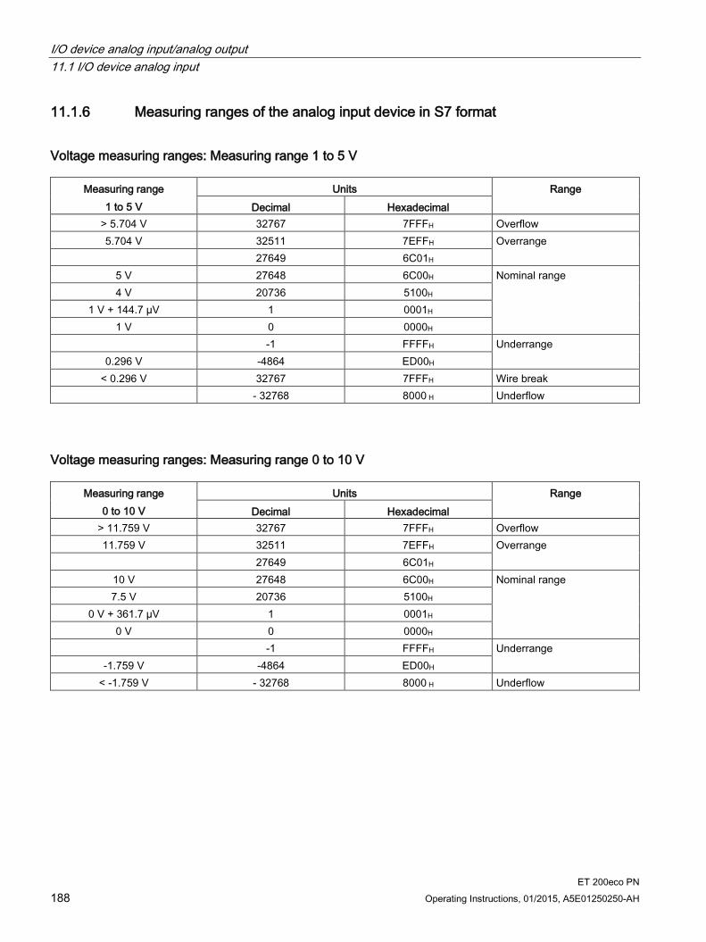
I/O device analog input/analog output 11.1 I/O device analog input
ET 200eco PN 188 Operating Instructions, 01/2015, A5E01250250-AH
11.1.6 Measuring ranges of the analog input device in S7 format
Voltage measuring ranges: Measuring range 1 to 5 V
Measuring range 1 to 5 V
Units Range Decimal Hexadecimal
> 5.704 V 32767 7FFFH Overflow 5.704 V 32511 7EFFH Overrange
27649 6C01H 5 V 27648 6C00H Nominal range 4 V 20736 5100H
1 V + 144.7 µV 1 0001H 1 V 0 0000H
-1 FFFFH Underrange 0.296 V -4864 ED00H
< 0.296 V 32767 7FFFH Wire break - 32768 8000 H Underflow
Voltage measuring ranges: Measuring range 0 to 10 V
Measuring range 0 to 10 V
Units Range Decimal Hexadecimal
> 11.759 V 32767 7FFFH Overflow 11.759 V 32511 7EFFH Overrange
27649 6C01H 10 V 27648 6C00H Nominal range 7.5 V 20736 5100H
0 V + 361.7 µV 1 0001H 0 V 0 0000H
-1 FFFFH Underrange -1.759 V -4864 ED00H
< -1.759 V - 32768 8000 H Underflow

I/O device analog input/analog output 11.1 I/O device analog input
ET 200eco PN Operating Instructions, 01/2015, A5E01250250-AH 189
Voltage measuring ranges: ±10 V
Measuring range ±10 V Units Range Decimal Hexadecimal
> 11.759 V 32767 7FFFH Overflow 11.759 V 32511 7EFFH Overrange
27649 6C01H 10 V 27648 6C00H Nominal range 7.5 V 20736 5100H
361.7 µV 1 0001H 0 V 0 0000H
-1 FFFFH - 7.5 V -20736 AF00H -10 V -27648 9400H
-27649 93FFH -11.759 V -32512 8100H Underrange
< -11.759 V -32768 8000H Underflow
Current measuring range: 0 to 20 mA
Measuring range 0 to 20 mA
Units Range Decimal Hexadecimal
> 23.52 mA 32767 7FFFH Overflow 23.52 mA 32511 7EFFH Overrange
27649 6C01H 20 mA 27648 6C00H Nominal range 15 mA 20736 5100H
723.4 nA 1 0001H 0 mA 0 0000H
- 1 FFFFH Underrange -3.52 mA -4864 ED00H
< -3.52 mA 32768 8000H Underflow

I/O device analog input/analog output 11.1 I/O device analog input
ET 200eco PN 190 Operating Instructions, 01/2015, A5E01250250-AH
Current measuring range: 4 to 20 mA
Measuring range 4 to 20 mA
Units Range Decimal Hexadecimal
> 22.81 mA 32767 7FFFH Overflow 22.81 mA 32511 7EFFH Overrange
27649 6C01H 20 mA 27648 6C00H Nominal range 16 mA 20736 5100H
4 mA + 578.7 nA 1 0001H 4 mA 0 0000H
- 1 FFFFH Underrange 11.85 mA -4864 ED00H
< 11.85 mA 32767 7FFFH Wire break -32768 8000 H Underflow
Current measuring range: ±20 mA
Measuring range ±20 mA Units Range Decimal Hexadecimal
> 23.52 mA 32767 7FFFH Overflow 23.52 mA 32511 7EFFH Overrange
27649 6C01H 20 mA 27648 6C00H Nominal range 15 mA 20736 5100H
723.4 nA 1 0001H 0 mA 0 0000H
-1 FFFFH -15 mA -20736 AF00H -20 mA -27648 9400H
-27649 93FFH Underrange -23.52 mA -32512 8100H
< -23.52 mA -32768 8000H Underflow
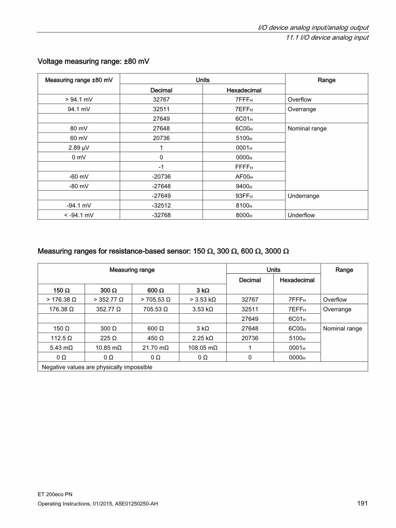
I/O device analog input/analog output 11.1 I/O device analog input
ET 200eco PN Operating Instructions, 01/2015, A5E01250250-AH 191
Voltage measuring range: ±80 mV
Measuring range ±80 mV Units Range Decimal Hexadecimal
> 94.1 mV 32767 7FFFH Overflow 94.1 mV 32511 7EFFH Overrange
27649 6C01H 80 mV 27648 6C00H Nominal range 60 mV 20736 5100H
2.89 µV 1 0001H 0 mV 0 0000H
-1 FFFFH -60 mV -20736 AF00H -80 mV -27648 9400H
-27649 93FFH Underrange -94.1 mV -32512 8100H
< -94.1 mV -32768 8000H Underflow
Measuring ranges for resistance-based sensor: 150 Ω, 300 Ω, 600 Ω, 3000 Ω
Measuring range Units Range Decimal Hexadecimal
150 Ω 300 Ω 600 Ω 3 kΩ > 176.38 Ω > 352.77 Ω > 705.53 Ω > 3.53 kΩ 32767 7FFFH Overflow 176.38 Ω 352.77 Ω 705.53 Ω 3.53 kΩ 32511 7EFFH Overrange
27649 6C01H 150 Ω 300 Ω 600 Ω 3 kΩ 27648 6C00H Nominal range
112.5 Ω 225 Ω 450 Ω 2.25 kΩ 20736 5100H 5.43 mΩ 10.85 mΩ 21.70 mΩ 108.05 mΩ 1 0001H
0 Ω 0 Ω 0 Ω 0 Ω 0 0000H Negative values are physically impossible
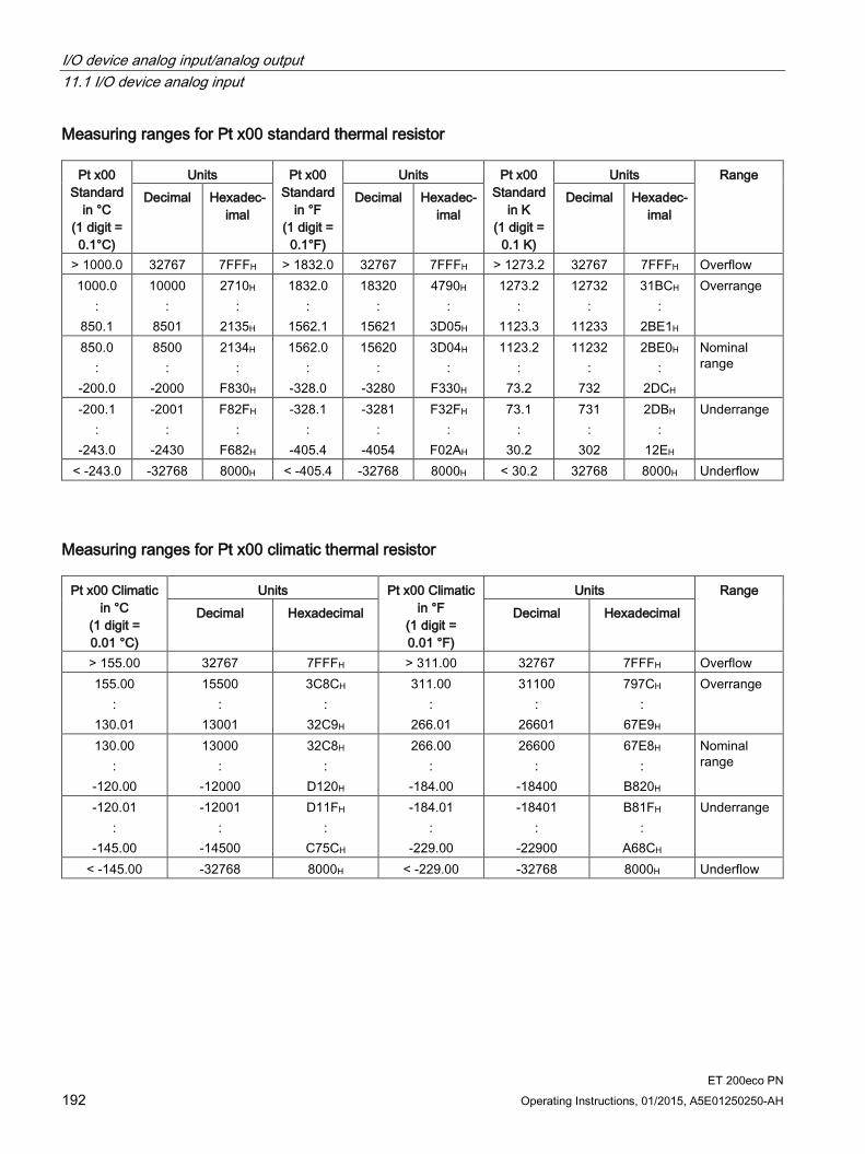
I/O device analog input/analog output 11.1 I/O device analog input
ET 200eco PN 192 Operating Instructions, 01/2015, A5E01250250-AH
Measuring ranges for Pt x00 standard thermal resistor
Pt x00 Standard
in °C (1 digit = 0.1°C)
Units Pt x00 Standard
in °F (1 digit =
0.1°F)
Units Pt x00 Standard
in K (1 digit =
0.1 K)
Units Range Decimal Hexadec-
imal Decimal Hexadec-
imal Decimal Hexadec-
imal
> 1000.0 32767 7FFFH > 1832.0 32767 7FFFH > 1273.2 32767 7FFFH Overflow 1000.0
: 850.1
10000 :
8501
2710H :
2135H
1832.0 :
1562.1
18320 :
15621
4790H :
3D05H
1273.2 :
1123.3
12732 :
11233
31BCH :
2BE1H
Overrange
850.0 :
-200.0
8500 :
-2000
2134H :
F830H
1562.0 :
-328.0
15620 :
-3280
3D04H :
F330H
1123.2 :
73.2
11232 :
732
2BE0H :
2DCH
Nominal range
-200.1 :
-243.0
-2001 :
-2430
F82FH :
F682H
-328.1 :
-405.4
-3281 :
-4054
F32FH :
F02AH
73.1 :
30.2
731 :
302
2DBH :
12EH
Underrange
< -243.0 -32768 8000H < -405.4 -32768 8000H < 30.2 32768 8000H Underflow
Measuring ranges for Pt x00 climatic thermal resistor
Pt x00 Climatic in °C
(1 digit = 0.01 °C)
Units Pt x00 Climatic in °F
(1 digit = 0.01 °F)
Units Range Decimal Hexadecimal Decimal Hexadecimal
> 155.00 32767 7FFFH > 311.00 32767 7FFFH Overflow 155.00
: 130.01
15500 :
13001
3C8CH :
32C9H
311.00 :
266.01
31100 :
26601
797CH :
67E9H
Overrange
130.00 :
-120.00
13000 :
-12000
32C8H :
D120H
266.00 :
-184.00
26600 :
-18400
67E8H :
B820H
Nominal range
-120.01 :
-145.00
-12001 :
-14500
D11FH :
C75CH
-184.01 :
-229.00
-18401 :
-22900
B81FH :
A68CH
Underrange
< -145.00 -32768 8000H < -229.00 -32768 8000H Underflow
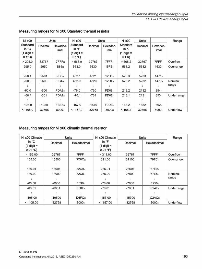
I/O device analog input/analog output 11.1 I/O device analog input
ET 200eco PN Operating Instructions, 01/2015, A5E01250250-AH 193
Measuring ranges for Ni x00 Standard thermal resistor
Ni x00 Standard
in °C (1 digit = 0.1°C)
Units Ni x00 Standard
in °F (1 digit =
0.1°F)
Units Ni x00 Standard
in K (1 digit =
0.1 K)
Units Range Decimal Hexadec-
imal Decimal Hexadec-
imal Decimal Hexadec-
imal
> 295.0 32767 7FFFH > 563.0 32767 7FFFH > 568.2 32767 7FFFH Overflow 295.0
: 250.1
2950 :
2501
B86H :
9C5H
563.0 :
482.1
5630 :
4821
15FEH :
12D5H
568.2 :
523.3
5682 :
5233
1632H :
1471H
Overrange
250.0 :
-60.0
2500 :
-600
9C4H :
FDA8H
482.0 :
-76.0
4820 :
-760
12D4H :
FD08H
523.2 :
213.2
5232 :
2132
1470H :
854H
Nominal range
-60.1 :
-105.0
-601 :
-1050
FDA7H :
FBE6H
-76.1 :
-157.0
-761 :
-1570
FD07H :
F9DEH
213.1 :
168.2
2131 :
1682
853H :
692H
Underrange
< -105.0 -32768 8000H < -157.0 -32768 8000H < 168.2 32768 8000H Underflow
Measuring ranges for Ni x00 climatic thermal resistor
Ni x00 Climatic in °C
(1 digit = 0.01 °C)
Units Ni x00 Climatic in °F
(1 digit = 0.01 °F)
Units Range Decimal Hexadecimal Decimal Hexadecimal
> 155.00 32767 7FFFH > 311.00 32767 7FFFH Overflow 155.00
: 130.01
15500 :
13001
3C8CH :
32C9H
311.00 :
266.01
31100 :
26601
797CH :
67E9H
Overrange
130.00 :
-60.00
13000 :
-6000
32C8H :
E890H
266.00 :
-76.00
26600 :
-7600
67E8H :
E250H
Nominal range
-60.01 :
-105.00
-6001 :
-10500
E88FH :
D6FCH
-76.01 :
-157.00
-7601 :
-15700
E24FH :
C2ACH
Underrange
< -105.00 -32768 8000H < -157.00 -32768 8000H Underflow
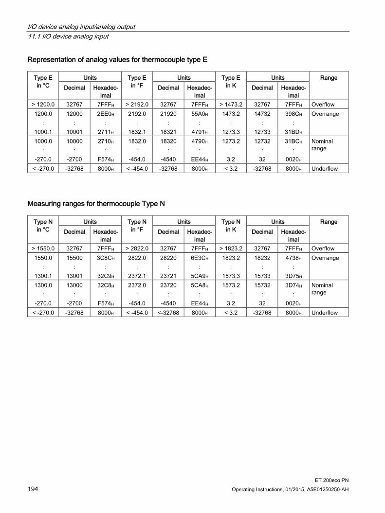
I/O device analog input/analog output 11.1 I/O device analog input
ET 200eco PN 194 Operating Instructions, 01/2015, A5E01250250-AH
Representation of analog values for thermocouple type E
Type E in °C
Units Type E in °F
Units Type E in K
Units Range Decimal Hexadec-
imal Decimal Hexadec-
imal Decimal Hexadec-
imal > 1200.0 32767 7FFFH > 2192.0 32767 7FFFH > 1473.2 32767 7FFFH Overflow 1200.0
: 1000.1
12000 :
10001
2EE0H :
2711H
2192.0 :
1832.1
21920 :
18321
55A0H :
4791H
1473.2 :
1273.3
14732 :
12733
398CH :
31BDH
Overrange
1000.0 :
-270.0
10000 :
-2700
2710H :
F574H
1832.0 :
-454.0
18320 :
-4540
4790H :
EE44H
1273.2 :
3.2
12732 :
32
31BCH :
0020H
Nominal range
< -270.0 -32768 8000H < -454.0 -32768 8000H < 3.2 -32768 8000H Underflow
Measuring ranges for thermocouple Type N
Type N in °C
Units Type N in °F
Units Type N in K
Units Range Decimal Hexadec-
imal Decimal Hexadec-
imal Decimal Hexadec-
imal > 1550.0 32767 7FFFH > 2822.0 32767 7FFFH > 1823.2 32767 7FFFH Overflow 1550.0
: 1300.1
15500 :
13001
3C8CH :
32C9H
2822.0 :
2372.1
28220 :
23721
6E3CH :
5CA9H
1823.2 :
1573.3
18232 :
15733
4738H :
3D75H
Overrange
1300.0 :
-270.0
13000 :
-2700
32C8H :
F574H
2372.0 :
-454.0
23720 :
-4540
5CA8H :
EE44H
1573.2 :
3.2
15732 :
32
3D74H :
0020H
Nominal range
< -270.0 -32768 8000H < -454.0 <-32768 8000H < 3.2 -32768 8000H Underflow
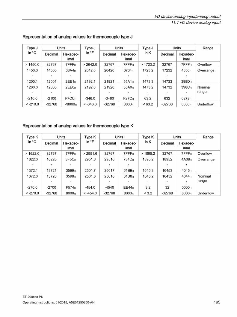
I/O device analog input/analog output 11.1 I/O device analog input
ET 200eco PN Operating Instructions, 01/2015, A5E01250250-AH 195
Representation of analog values for thermocouple type J
Type J in °C
Units Type J in °F
Units Type J in K
Units Range Decimal Hexadec-
imal Decimal Hexadec-
imal Decimal Hexadec-
imal > 1450.0 32767 7FFFH > 2642.0 32767 7FFFH > 1723.2 32767 7FFFH Overflow 1450.0
: 1200.1
14500 :
12001
38A4H :
2EE1H
2642.0 :
2192.1
26420 :
21921
6734H :
55A1H
1723.2 :
1473.3
17232 :
14733
4350H :
398DH
Overrange
1200.0 :
-210.0
12000 :
-2100
2EE0H :
F7CCH
2192.0 :
-346.0
21920 :
-3460
55A0H :
F27CH
1473.2 :
63.2
14732 :
632
398CH :
0278H
Nominal range
< -210.0 -32768 <8000H < -346.0 -32768 8000H < 63.2 -32768 8000H Underflow
Representation of analog values for thermocouple type K
Type K in °C
Units Type K in °F
Units Type K in K
Units Range Decimal Hexadec-
imal Decimal Hexadec-
imal Decimal Hexadec-
imal > 1622.0 32767 7FFFH > 2951.6 32767 7FFFH > 1895.2 32767 7FFFH Overflow 1622.0
: 1372.1
16220 :
13721
3F5CH :
3599H
2951.6 :
2501.7
29516 :
25017
734CH :
61B9H
1895.2 :
1645.3
18952 :
16453
4A08H :
4045H
Overrange
1372.0 :
-270.0
13720 :
-2700
3598H :
F574H
2501.6 :
-454.0
25016 :
-4540
61B8H :
EE44H
1645.2 :
3.2
16452 :
32
4044H :
0000H
Nominal range
< -270.0 -32768 8000H < -454.0 -32768 8000H < 3.2 -32768 8000H Underflow
I/O device analog input/analog output 11.1 I/O device analog input
ET 200eco PN 196 Operating Instructions, 01/2015, A5E01250250-AH
11.1.7 Dynamic reference temperature with module 8 AI RTD/TC 8xM12
Properties You can measure the reference junction temperature of the measuring point by using the I/O device 8 AI RTD/TC 8xM12 or an external module from another station when you use the compensation type "Dynamic reference temperature". To do so, the reference temperature is transmitted with SFB 53 "WRREC" using the data record DS2 to the I/O device 8 AI RTD/TC 8xM12.
Requirements Standard function block SFB 53 "WRREC"
User program
Programming Observe the following notes on the user program:
The permitted value range of the reference junction temperature in standard resolution corresponds to the temperature range Pt100 Climatic for platinum RTDs.
If a reference junction temperature is received in data record DS2 that is outside the permitted value range, a diagnostic interrupt "Reference channel fault" is signaled if the "Group diagnostics" parameter has been enabled.
All inputs signal overflow (32767) when you start the I/O device 8 AI RTD/TC 8xM12. After receiving a compensation value by means of the data record DS2, the I/O device starts reading the TC inputs and signals correct data.
The I/O device 8 AI RTD/TC 8xM12 has a watchdog set to 5 minutes that is reset after a new compensation value was received by means of DS2. If the I/O device in standard operation does not receive DS2 data within the 5-minute interval of the watchdog, a diagnostic interrupt "Reference channel fault" is signaled if the "Group diagnostics" parameter has been enabled.
When you use ET 200eco PN modules or other modules for measuring the reference junction temperature, the RTD module parameters/module parameters for the output structure and measuring accuracy must be represented in the DS2 by bytes 0 and 1. The figure below "Structure of data record DS2" illustrates this setting.
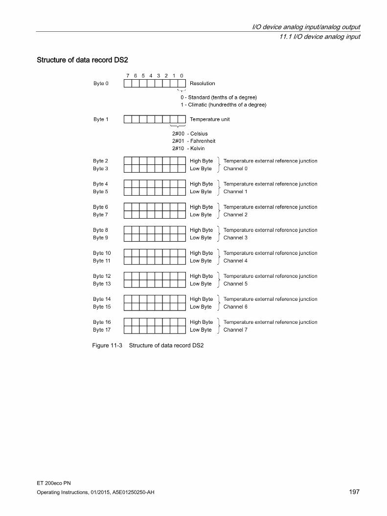
I/O device analog input/analog output 11.1 I/O device analog input
ET 200eco PN Operating Instructions, 01/2015, A5E01250250-AH 197
Structure of data record DS2
Figure 11-3 Structure of data record DS2

I/O device analog input/analog output 11.1 I/O device analog input
ET 200eco PN 198 Operating Instructions, 01/2015, A5E01250250-AH
Table 11- 7 Reference temperature for TC
Temperature unit Decimal Hexadecimal Standard temperature unit Celsius -1450 to 1550 FA56H to 60EH Fahrenheit -2290 to 3110 F70EH to C26H Kelvin 1282 to 4282 502H to 10BAH Climatic temperature unit Celsius -14500 to 15500 C75CH to 3C8CH Fahrenheit -22900 to 31100 A68CH to 797CH Kelvin 12815 to 32760 320FH to 7FF8H
Note
You can use a separate reference junction for each channel due to the flexible structure of the data record DS2. You can also combine channels with the user program so that they use the same reference junction. All channels that operate with the same reference junction temperature must have the same temperature value in the DS2.
User program The following user program shows an example for the compensation type "Dynamic reference temperature" of channels 0 to 7 of the I/O device 8 AI RTD/TC 8xM12 of an RTD module. The reference junction temperature of the RTD module applies to all channels of the I/O device 8 AI RTD/TC 8xM12.
Requirements:
Input address of the I/O device 8 AI RTD/TC 8xM12: 120 (module address)
Input address of the RTD module: 136 (channel address)
Request bit for SFB "WRREC": M 20.0
Busy bit for SFB "WRREC": M 20.1
Memory for data transmission: MW 0 to MW 16
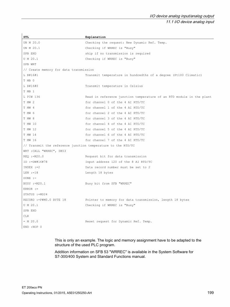
I/O device analog input/analog output 11.1 I/O device analog input
ET 200eco PN Operating Instructions, 01/2015, A5E01250250-AH 199
STL Explanation
UN M 20.0 Checking the request: New Dynamic Ref. Temp.
UN M 20.1 Checking if WRREC is "Busy"
SPB END skip if no transmission is required
U M 20.1 Checking if WRREC is "Busy"
SPB WRT
// Create memory for data transmission
L B#16#1 Transmit temperature in hundredths of a degree (Pt100 Climatic)
T MB 0
L B#16#0 Transmit temperature in Celsius
T MB 1
L PIW 136 Read in reference junction temperature of an RTD module in the plant
T MW 2 for channel 0 of the 4 AI RTD/TC
T MW 4 for channel 1 of the 4 AI RTD/TC
T MW 6 for channel 2 of the 4 AI RTD/TC
T MW 8 for channel 3 of the 4 AI RTD/TC
T MW 10 for channel 4 of the 4 AI RTD/TC
T MW 12 for channel 5 of the 4 AI RTD/TC
T MW 14 for channel 6 of the 4 AI RTD/TC
T MW 16 for channel 7 of the 4 AI RTD/TC
// Transmit the reference junction temperature to the RTD/TC
WRT :CALL "WRREC", DB53
REQ :=M20.0 Request bit for data transmission
ID :=DW#16#78 Input address 120 of the 8 AI RTD/TC
INDEX :=2 Data record number must be set to 2
LEN :=18 Length 18 bytes
DONE :=
BUSY :=M20.1 Busy bit from SFB "WRREC"
ERROR :=
STATUS :=MD24
RECORD :=P#M0.0 BYTE 18 Pointer to memory for data transmission, length 18 bytes
U M 20.1 Checking if WRREC is "Busy"
SPB END
CLR
= M 20.0 Reset request for Dynamic Ref. Temp.
END :NOP 0
This is only an example. The logic and memory assignment have to be adapted to the structure of the used PLC program.
Addition information on SFB 53 "WRREC" is available in the System Software for S7-300/400 System and Standard Functions manual.

I/O device analog input/analog output 11.2 I/O device analog output
ET 200eco PN 200 Operating Instructions, 01/2015, A5E01250250-AH
11.2 I/O device analog output
11.2.1 I/O device 4 AO U/I 4xM12
Order number 6ES7145-6HD00-0AB0
Properties 4 outputs for voltage or current output
Output ranges:
– ±10 V, resolution 15 bits + sign
– 1 to 5 V, resolution 15 bits
– 0 to 10 V, resolution 15 bits
– ±20 mA, resolution 15 bits + sign
– 4 to 20 mA, resolution 15 bits
– 0 to 20 mA, resolution 15 bits
Supply voltage DC 24 V
Dimensions 60 x 175 mm
Diagnostics
– "Missing 1L+" supply voltage
– "Sensor supply short-circuit"
– "Wire break"
– "Short-circuit"
– "Overload"
Parameterizable response to CPU/Master STOP
Prioritized startup
Media redundancy
Note
Incorrect intermediate values at the output are possible when supply voltage 1L+ is switched on and off.
Note
The outputs are in voltage mode and supply a signal 0 V until the parameter assignment becomes effective after switching on.

I/O device analog input/analog output 11.2 I/O device analog output
ET 200eco PN Operating Instructions, 01/2015, A5E01250250-AH 201
Pin assignment You will find the pin assignment for the 4 AO U/I 4×M12 I/O device in the table below.
Table 11- 8 Pin assignment for voltage and current for the 4 AO U/I 4×M12 I/O device
Pin Assignment for U/I View of socket (front view) Socket X1 Socket X2 Socket X3 Socket X4
1 24 V actuator supply 1UA(derived from 1L+ non-switched)
2 Output signal Q0+ Q1+ Q2+ Q3+
3 Actuator supply ground 1M 4 Output signal
Q0- Q1- Q2- Q3- 5 Functional earth FE
Block diagram The block diagram below shows the 4 AO U/I 4×M12.
Figure 11-4 Block diagram 4 AO U/I 4xM12

I/O device analog input/analog output 11.2 I/O device analog output
ET 200eco PN 202 Operating Instructions, 01/2015, A5E01250250-AH
Technical data Technical data Dimensions and weight Dimensions W x H x D (mm) 60 x 175 x 49 Weight Approx. 930 g Module-specific data Transmission rate 100 Mbps full duplex Transmission mode 100BASE-TX Autonegotiation Yes Bus protocol PROFINET IO
• IRT with the option "high flexibility" • IRT with the option "high performance"
Supported Ethernet services PROFINET IO (Device) • ping • arp • LLDP • Network diagnostics (SNMP) • DCP • Prioritized startup • Media redundancy
PROFINET interface
• Connection socket 2 x M12 d-coded
• Switch function Yes, internal
• Auto-crossover Yes, if autonegotiation is enabled
Manufacturer ID (Vendor ID) 002AH Device ID (DeviceID) 0306H Voltages and currents Supply voltage 1L+ DC 24 V Reverse polarity protection Yes; against destruction
• Infeed current 1L+ Max. 4 A
Supply voltage 2L+ DC 24 V
• Infeed current 2L+ Max. 4 A
Current consumption
• From supply voltage (1L+) Typ. 280 mA
• From supply voltage (2L+) 0 A
Power loss of the device Typ. 5.5 W Analog outputs Number of outputs 4 Cable length, shielded Max. 30 m

I/O device analog input/analog output 11.2 I/O device analog output
ET 200eco PN Operating Instructions, 01/2015, A5E01250250-AH 203
Technical data Voltage
• Short-circuit protection Yes, electronic, to ground
• Short-circuit current Max. 30 mA
Current
• No-load voltage Max. 20 V
Actuator supplies Number of actuator supplies 4 Total current Max. 1 A Short-circuit protection Yes, electronic
• Response threshold Min. 1.4 A
Actuator selection data Output ranges (Rated value) Voltage ±10 V
1 V to 5 V 0 V to 10 V
Current ±20 mA 4 to 20 mA 0 to 20 mA
Load resistance (in the Rated range of the output)
• For voltage outputs Min. 1 kΩ
• For voltage outputs, capacitive load Max. 1 μF
• For current outputs Max. 0.6 kΩ
• For current outputs, inductive load Max. 1 mH
Permissible input voltage at the output (destruction limit)
28.8 V continuous, 35 V for 500 ms
Connection of actuators
• For voltage output, 2-wire connection Yes
• For current output, 2-wire connection Yes
Formation of analog values Conversion principle Resistor network
• Conversion time per channel, in ms 1 ms
• Voltage resolution (including overrange) ±10 V/15 bits + sign 1 to 5 V/15 bits 0 to 10 V/15 bits
• Current resolution (including overrange) ±20 mA/15 bits + sign 4 to 20 mA/15 bits 0 to 20 mA/15 bits
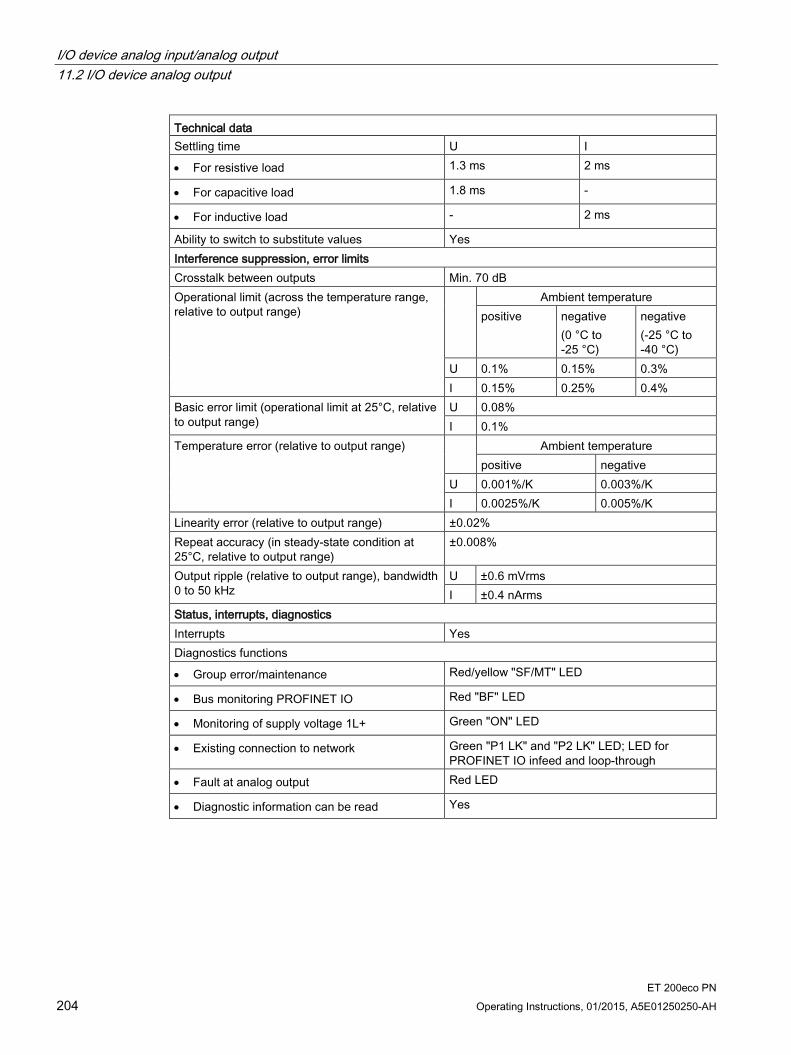
I/O device analog input/analog output 11.2 I/O device analog output
ET 200eco PN 204 Operating Instructions, 01/2015, A5E01250250-AH
Technical data Settling time U I
• For resistive load 1.3 ms 2 ms
• For capacitive load 1.8 ms -
• For inductive load - 2 ms
Ability to switch to substitute values Yes Interference suppression, error limits Crosstalk between outputs Min. 70 dB Operational limit (across the temperature range, relative to output range)
Ambient temperature positive negative
(0 °C to -25 °C)
negative (-25 °C to -40 °C)
U 0.1% 0.15% 0.3% I 0.15% 0.25% 0.4%
Basic error limit (operational limit at 25°C, relative to output range)
U 0.08% I 0.1%
Temperature error (relative to output range) Ambient temperature positive negative
U 0.001%/K 0.003%/K I 0.0025%/K 0.005%/K
Linearity error (relative to output range) ±0.02% Repeat accuracy (in steady-state condition at 25°C, relative to output range)
±0.008%
Output ripple (relative to output range), bandwidth 0 to 50 kHz
U ±0.6 mVrms I ±0.4 nArms
Status, interrupts, diagnostics Interrupts Yes Diagnostics functions
• Group error/maintenance Red/yellow "SF/MT" LED
• Bus monitoring PROFINET IO Red "BF" LED
• Monitoring of supply voltage 1L+ Green "ON" LED
• Existing connection to network Green "P1 LK" and "P2 LK" LED; LED for PROFINET IO infeed and loop-through
• Fault at analog output Red LED
• Diagnostic information can be read Yes

I/O device analog input/analog output 11.2 I/O device analog output
ET 200eco PN Operating Instructions, 01/2015, A5E01250250-AH 205
Technical data Monitoring for
• Supply voltage 1L+ Yes
• Sensor supply short-circuit Yes
• Short-circuit Yes; channel (voltage)
• Wire break Yes; channel (current)
• Thermal overload at output Yes; channel
Insulation Insulation test voltage DC 500 V Ethernet interface 1500 Vrms (IEEE802.3) Electrical isolation
• Between 1L+ and 2L+ Yes
• Between 1L+, channels and all other circuit elements
No
• Between channels No
• Between Ethernet and all other circuit elements
Yes
Permitted potential difference
• Between current outputs and 1M (UCM) 10 V ACPP
See also Response times for analog input device and output device (Page 241)
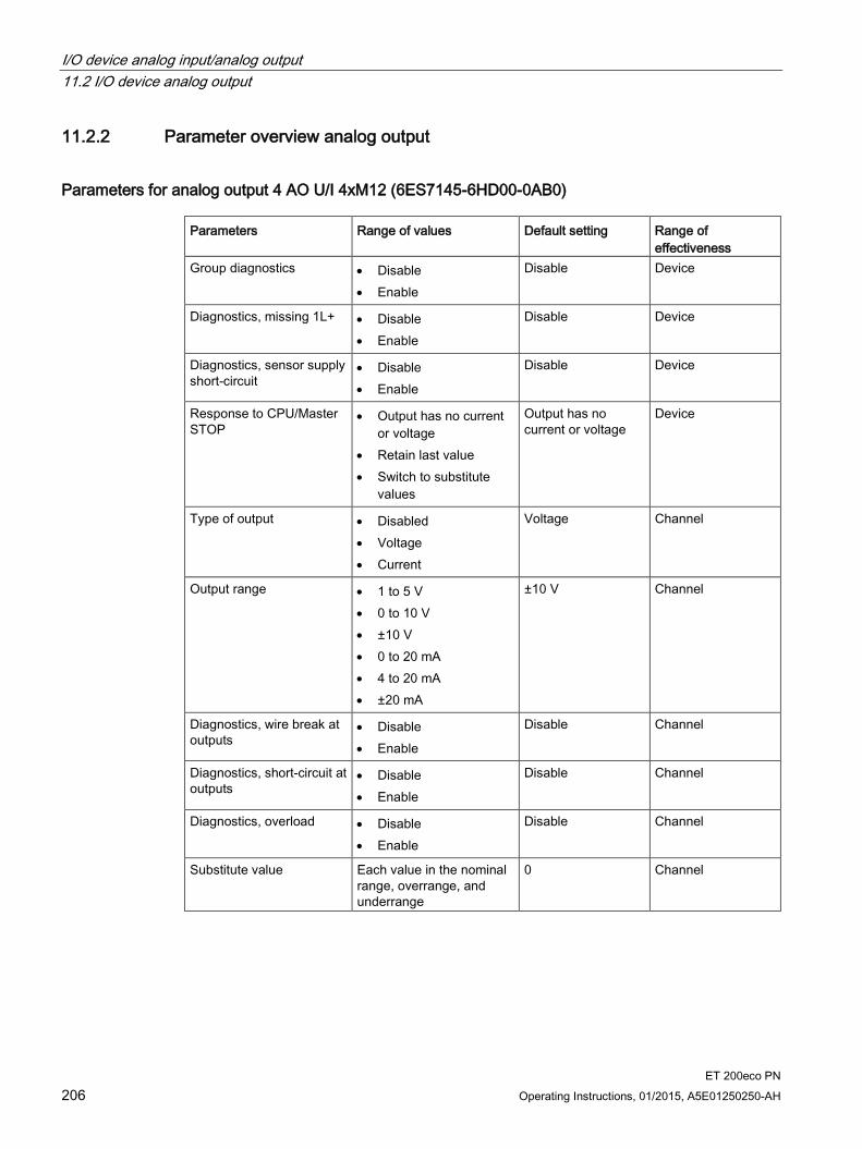
I/O device analog input/analog output 11.2 I/O device analog output
ET 200eco PN 206 Operating Instructions, 01/2015, A5E01250250-AH
11.2.2 Parameter overview analog output
Parameters for analog output 4 AO U/I 4xM12 (6ES7145-6HD00-0AB0) Parameters Range of values Default setting Range of
effectiveness Group diagnostics • Disable
• Enable
Disable Device
Diagnostics, missing 1L+ • Disable • Enable
Disable Device
Diagnostics, sensor supply short-circuit
• Disable • Enable
Disable Device
Response to CPU/Master STOP
• Output has no current or voltage
• Retain last value • Switch to substitute
values
Output has no current or voltage
Device
Type of output • Disabled • Voltage • Current
Voltage Channel
Output range • 1 to 5 V • 0 to 10 V • ±10 V • 0 to 20 mA • 4 to 20 mA • ±20 mA
±10 V Channel
Diagnostics, wire break at outputs
• Disable • Enable
Disable Channel
Diagnostics, short-circuit at outputs
• Disable • Enable
Disable Channel
Diagnostics, overload • Disable • Enable
Disable Channel
Substitute value Each value in the nominal range, overrange, and underrange
0 Channel
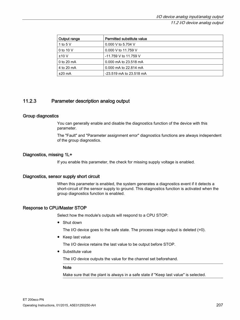
I/O device analog input/analog output 11.2 I/O device analog output
ET 200eco PN Operating Instructions, 01/2015, A5E01250250-AH 207
Output range Permitted substitute value 1 to 5 V 0.000 V to 5.704 V 0 to 10 V 0.000 V to 11.759 V ±10 V -11.759 V to 11.759 V 0 to 20 mA 0.000 mA to 23.518 mA 4 to 20 mA 0.000 mA to 22.814 mA ±20 mA -23.519 mA to 23.518 mA
11.2.3 Parameter description analog output
Group diagnostics You can generally enable and disable the diagnostics function of the device with this parameter.
The "Fault" and "Parameter assignment error" diagnostics functions are always independent of the group diagnostics.
Diagnostics, missing 1L+ If you enable this parameter, the check for missing supply voltage is enabled.
Diagnostics, sensor supply short circuit When this parameter is enabled, the system generates a diagnostics event if it detects a short-circuit of the sensor supply to ground. This diagnostics function is activated when the group diagnostics function is enabled.
Response to CPU/Master STOP Select how the module's outputs will respond to a CPU STOP:
Shut down
The I/O device goes to the safe state. The process image output is deleted (=0).
Keep last value
The I/O device retains the last value to be output before STOP.
Substitute value
The I/O device outputs the value for the channel set beforehand.
Note
Make sure that the plant is always in a safe state if "Keep last value" is selected.

I/O device analog input/analog output 11.2 I/O device analog output
ET 200eco PN 208 Operating Instructions, 01/2015, A5E01250250-AH
Type of output With this parameter, you set the output type, for example, voltage. For any unused channels, select the disabled setting. For a disabled channel, the conversion time and integration time of the channel = 0 s, and the cycle time is optimized.
Output range With this parameter, you set the output range of the selected output type.
Diagnostics, wire break (in current mode) When this parameter is enabled, the Wire break diagnostics event is generated when a wire break is detected. This diagnostics event cannot be detected in the zero range.
Diagnostics, short circuit (in voltage mode) If you enable this parameter, a diagnostics event is generated in the event of a short circuit in the output line. This diagnostics event cannot be detected in the zero range.
Diagnostics, overload If you enable this parameter, the diagnostics event is generated in the event of an overload.
Substitute values With this parameter, you enter a substitute value that the module is to output in CPU-STOP mode. The substitute value must be in the nominal range, overrange, or underrange.
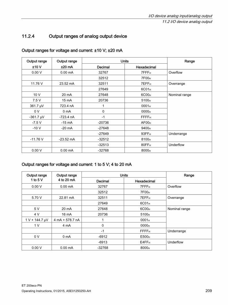
I/O device analog input/analog output 11.2 I/O device analog output
ET 200eco PN Operating Instructions, 01/2015, A5E01250250-AH 209
11.2.4 Output ranges of analog output device
Output ranges for voltage and current: ±10 V; ±20 mA
Output range ±10 V
Output range ±20 mA
Units Range Decimal Hexadecimal
0.00 V 0.00 mA 32767 7FFFH Overflow 32512 7F00H
11.76 V 23.52 mA 32511 7EFFH Overrange 27649 6C01H
10 V 20 mA 27648 6C00H Nominal range 7.5 V 15 mA 20736 5100H
361.7 μV 723.4 nA 1 0001H 0 V 0 mA 0 0000H
-361.7 μV -723.4 nA -1 FFFFH -7.5 V -15 mA -20736 AF00H -10 V -20 mA -27648 9400H
-27649 93FFH Underrange -11.76 V -23.52 mA -32512 8100H
-32513 80FFH Underflow 0.00 V 0.00 mA -32768 8000H
Output ranges for voltage and current: 1 to 5 V; 4 to 20 mA
Output range 1 to 5 V
Output range 4 to 20 mA
Units Range Decimal Hexadecimal
0.00 V 0.00 mA 32767 7FFFH Overflow 32512 7F00H
5.70 V 22.81 mA 32511 7EFFH Overrange 27649 6C01H
5 V 20 mA 27648 6C00H Nominal range 4 V 16 mA 20736 5100H
1 V + 144.7 µV 4 mA + 578.7 nA 1 0001H 1 V 4 mA 0 0000H
-1 FFFFH Underrange 0 V 0 mA -6912 E500H
-6913 E4FFH Underflow 0.00 V 0.00 mA -32768 8000H
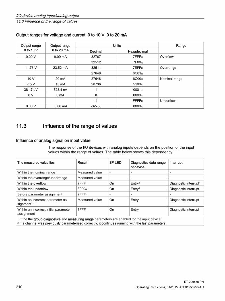
I/O device analog input/analog output 11.3 Influence of the range of values
ET 200eco PN 210 Operating Instructions, 01/2015, A5E01250250-AH
Output ranges for voltage and current: 0 to 10 V; 0 to 20 mA
Output range 0 to 10 V
Output range 0 to 20 mA
Units Range Decimal Hexadecimal
0.00 V 0.00 mA 32767 7FFFH Overflow 32512 7F00H
11.76 V 23.52 mA 32511 7EFFH Overrange 27649 6C01H
10 V 20 mA 27648 6C00H Nominal range 7.5 V 15 mA 20736 5100H
361.7 μV 723.4 nA 1 0001H 0 V 0 mA 0 0000H
-1 FFFFH Underflow 0.00 V 0.00 mA -32768 8000H
11.3 Influence of the range of values
Influence of analog signal on input value The response of the I/O devices with analog inputs depends on the position of the input values within the range of values. The table below shows this dependency.
The measured value lies Result SF LED Diagnostics data range
of device Interrupt
Within the nominal range Measured value - - - Within the overrange/underrange Measured value - - - Within the overflow 7FFFH On Entry1 Diagnostic interrupt1 Within the underflow 8000H On Entry1 Diagnostic interrupt1 Before parameter assignment 7FFFH - - - Within an incorrect parameter as-signment2
Measured value On Entry Diagnostic interrupt
Within an incorrect initial parameter assignment
7FFFH On Entry Diagnostic interrupt
1 If the the group diagnostics and measuring range parameters are enabled for the input device. 2 If a channel was previously parameterized correctly, it continues running with the last parameters.
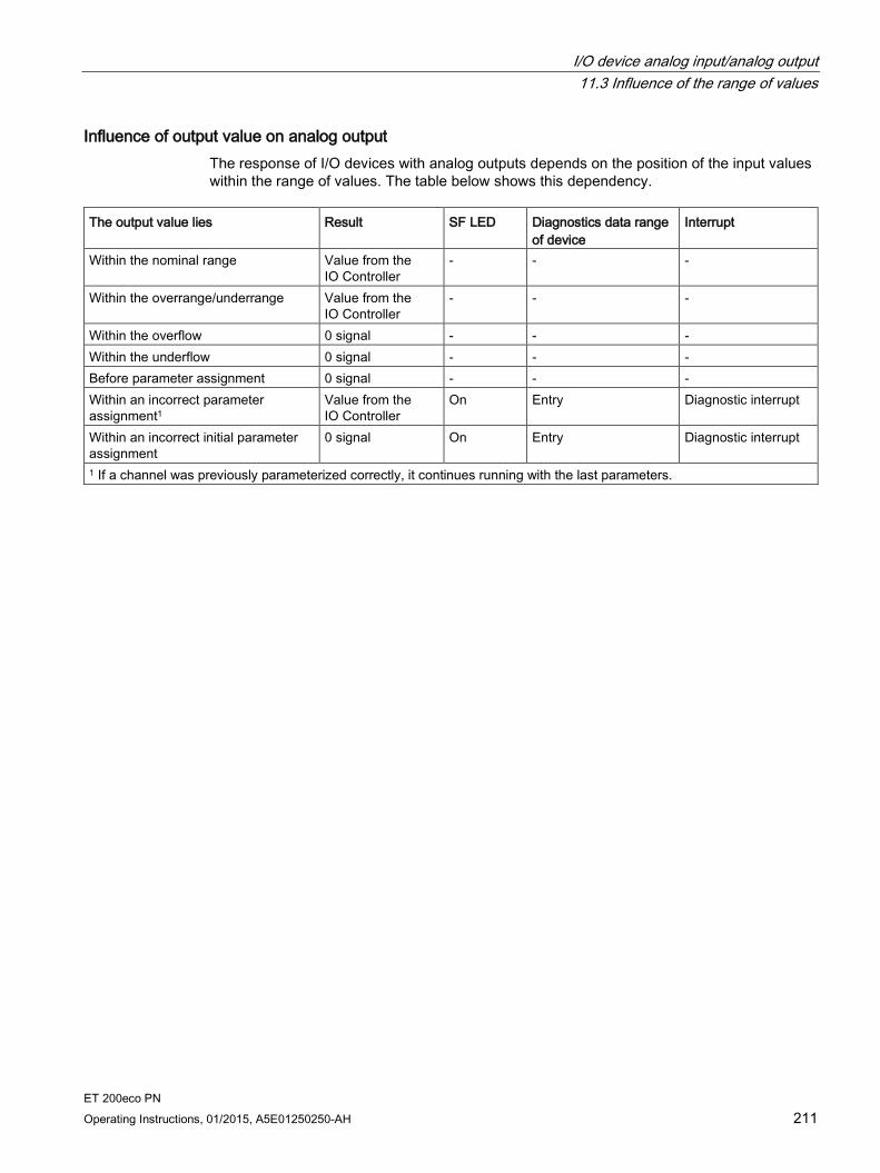
I/O device analog input/analog output 11.3 Influence of the range of values
ET 200eco PN Operating Instructions, 01/2015, A5E01250250-AH 211
Influence of output value on analog output The response of I/O devices with analog outputs depends on the position of the input values within the range of values. The table below shows this dependency.
The output value lies Result SF LED Diagnostics data range
of device Interrupt
Within the nominal range Value from the IO Controller
- - -
Within the overrange/underrange Value from the IO Controller
- - -
Within the overflow 0 signal - - - Within the underflow 0 signal - - - Before parameter assignment 0 signal - - - Within an incorrect parameter assignment1
Value from the IO Controller
On Entry Diagnostic interrupt
Within an incorrect initial parameter assignment
0 signal On Entry Diagnostic interrupt
1 If a channel was previously parameterized correctly, it continues running with the last parameters.

ET 200eco PN 212 Operating Instructions, 01/2015, A5E01250250-AH
Terminal block and voltage distributor 12 12.1 Terminal block
Order number 6ES7194-6CA00-0AA0
Properties The terminal block has the following properties:
The terminal block can be inserted and screw-mounted on any I/O device
It can also be used separately.
It distributes 10 A per supply voltage 1L+ and 2L+ to the I/O devices. You can tap a maximum load of 4 A from each supply voltage of the I/O device. The voltages are protected with two 7.5 A fuses.
Pin assignment The tables below show the pin assignments.
Table 12- 1 Pin assignment of the insulation displacement terminal block.
Pin Assignment View of the insulation displacement terminal block: 1 24 V (1L+ non-switched)
2 Ground 1M (non-switched) 3 24 V (2L+ switched) 4 Ground 2M (switched)
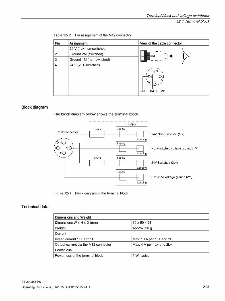
Terminal block and voltage distributor 12.1 Terminal block
ET 200eco PN Operating Instructions, 01/2015, A5E01250250-AH 213
Table 12- 2 Pin assignment of the M12 connector
Pin Assignment View of the cable connector 1 24 V (1L+ non-switched)
2 Ground 2M (switched) 3 Ground 1M (non-switched) 4 24 V (2L+ switched)
Block diagram The block diagram below shows the terminal block.
Figure 12-1 Block diagram of the terminal block
Technical data Dimensions and Weight Dimensions W x H x D (mm) 30 x 50 x 98 Weight Approx. 90 g Current Infeed current 1L+ and 2L+ Max. 10 A per 1L+ and 2L+ Output current via the M12 connector Max. 4 A per 1L+ and 2L+ Power loss Power loss of the terminal block 1 W, typical
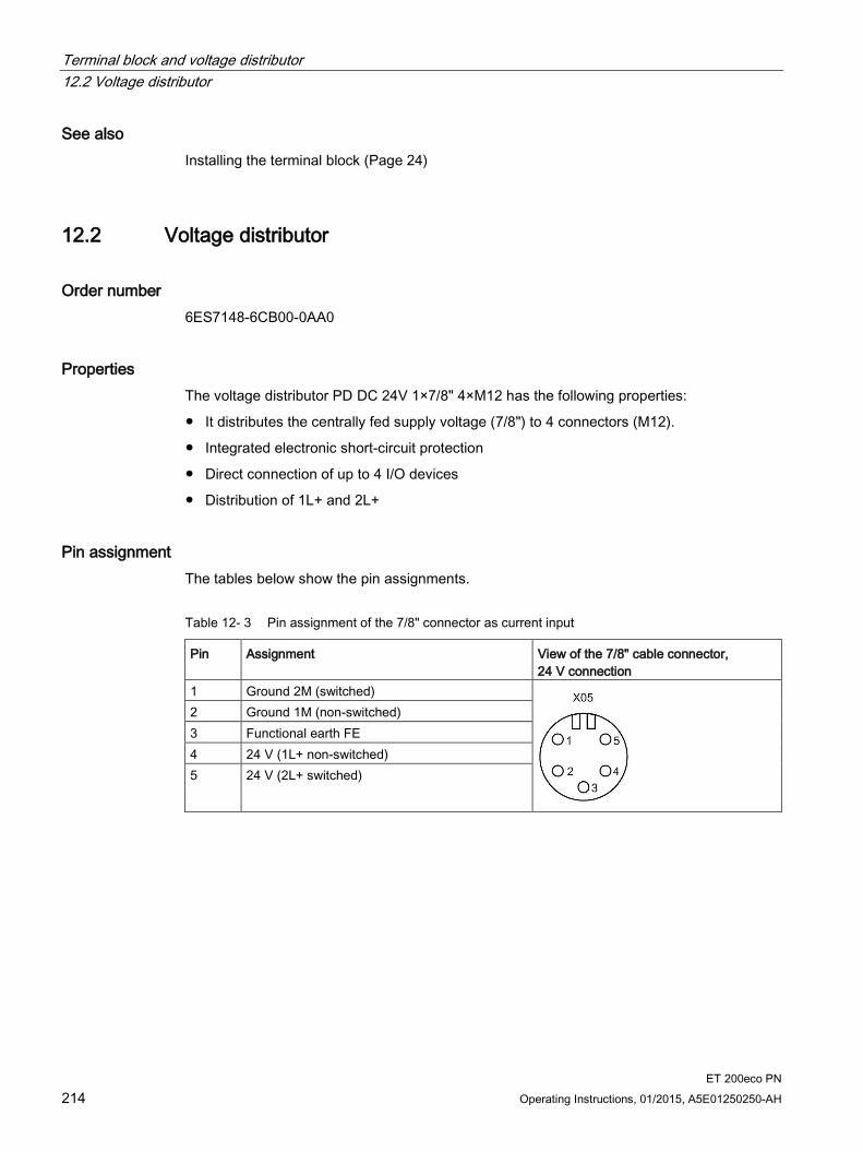
Terminal block and voltage distributor 12.2 Voltage distributor
ET 200eco PN 214 Operating Instructions, 01/2015, A5E01250250-AH
See also Installing the terminal block (Page 24)
12.2 Voltage distributor
Order number 6ES7148-6CB00-0AA0
Properties The voltage distributor PD DC 24V 1×7/8" 4×M12 has the following properties:
It distributes the centrally fed supply voltage (7/8") to 4 connectors (M12).
Integrated electronic short-circuit protection
Direct connection of up to 4 I/O devices
Distribution of 1L+ and 2L+
Pin assignment The tables below show the pin assignments.
Table 12- 3 Pin assignment of the 7/8" connector as current input
Pin Assignment View of the 7/8" cable connector, 24 V connection
1 Ground 2M (switched)
2 Ground 1M (non-switched) 3 Functional earth FE 4 24 V (1L+ non-switched) 5 24 V (2L+ switched)

Terminal block and voltage distributor 12.2 Voltage distributor
ET 200eco PN Operating Instructions, 01/2015, A5E01250250-AH 215
Table 12- 4 Pin assignment of the M12 connector as current output
Pin Assignment View of the M12 connection plug (front view)
1 24 V (1L+ non-switched)
2 Ground 2M (switched) 3 Ground 1M (non-switched) 4 24 V (2L+ switched) 5 Not used
Block diagram The figure below shows the block diagram of the voltage distributor PD DC 24V 1×7/8" 4×M12.
Figure 12-2 Block diagram of the voltage distributor PD DC 24V 1×7/8" 4×M12

Terminal block and voltage distributor 12.2 Voltage distributor
ET 200eco PN 216 Operating Instructions, 01/2015, A5E01250250-AH
Technical data Dimensions and Weight Dimensions W x H x D (mm) 45 x 175 x 49 Weight Approx. 590 g Voltages and currents Supply voltage 1L+ DC 24 V
• Reverse polarity protection Yes; against destruction (continuously without load)
• Infeed current 1L+ 8 A
Supply voltage 2L+ DC 24 V
• Reverse polarity protection Yes; against destruction (continuously without load)
• Infeed current 2L+ 8 A
Total current of the outputs
• All mounting positions to 45 °C for X1 and X2 in total max. 4 A for 1L+ for X1 and X2 in total max. 4 A for 2L+ for X3 and X4 in total max. 4 A for 1L+ for X3 and X4 in total max. 4 A for 2L+
• All mounting positions to 55 °C for X1 and X2 in total max. 3 A for 1L+ for X1 and X2 in total max. 3 A for 2L+ for X3 and X4 in total max. 3 A for 1L+ for X3 and X4 in total max. 3 A for 2L+
• Number of outputs 4, with 1L+ and 2L+ each
Input voltage/loop-through Green LED "1L+" and "2L+"
• Nominal value DC 24 V
Short-circuit protection of the output Yes, electronic
• Response threshold Typ. 4.5 A
Power loss of the voltage distributor Typ. 3.5 W Insulation Insulation test voltage DC 500 V Ethernet interface 1500 Vrms (IEEE802.3) Electrical isolation
• Between 1L+ and 2L+ Yes
Status, interrupts, diagnostics Diagnostics functions
• Input/output voltage Green LED "1L" and "2L"

ET 200eco PN Operating Instructions, 01/2015, A5E01250250-AH 217
Signal names A A.1 Signal names
Signal names of the I/O devices
Table A- 1 Signal names of the digital inputs and digital outputs (DI/DQ)
Signal name Meaning xL+ Input external auxiliary voltage DC (x: load group) xM Ground external auxiliary voltage DC (x: load group)
DIxUs Digital input (x: load group) DQxUs Digital output (x: load group) DIQxUs Digital input/digital output (x: load group)
USn Sensor supply voltage, channel n 1US 24 V sensor supply 1US(derived from 1L+ non-switched)
Table A- 2 Signal names of the analog inputs (AI)
Signal name Meaning xL+ Input external auxiliary voltage (x: load group) xM Ground external auxiliary voltage (x: load group) Mn+ Measuring input channel n (voltage, current, RTD, TC, etc.) Mn- Measuring input channel n (voltage, current, RTD, TC, etc.) ICn+ Power output power supply RTD channel n ICn- Power output power supply RTD channel n
UVn+ Infeed voltage for 2DMU USn Sensor supply voltage, channel n 1US 24 V sensor supply 1US(derived from 1L+ non-switched)
Table A- 3 Signal names of the analog outputs (AQ)
Signal name Meaning xL+ Input external auxiliary voltage (x: load group) xM Ground external auxiliary voltage (x: load group) Qn+ Output channel n (current or voltage) Qn- Output channel n (current or voltage) UAn Actuator supply voltage, channel n
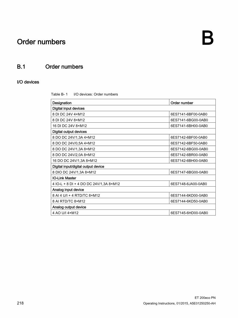
ET 200eco PN 218 Operating Instructions, 01/2015, A5E01250250-AH
Order numbers B B.1 Order numbers
I/O devices
Table B- 1 I/O devices: Order numbers
Designation Order number Digital input devices 8 DI DC 24V 4×M12 6ES7141-6BF00-0AB0 8 DI DC 24V 8×M12 6ES7141-6BG00-0AB0 16 DI DC 24V 8×M12 6ES7141-6BH00-0AB0 Digital output devices 8 DO DC 24V/1,3A 4×M12 6ES7142-6BF00-0AB0 8 DO DC 24V/0,5A 4×M12 6ES7142-6BF50-0AB0 8 DO DC 24V/1,3A 8×M12 6ES7142-6BG00-0AB0 8 DO DC 24V/2,0A 8×M12 6ES7142-6BR00-0AB0 16 DO DC 24V/1,3A 8×M12 6ES7142-6BH00-0AB0 Digital input/digital output device 8 DIO DC 24V/1,3A 8×M12 6ES7147-6BG00-0AB0 IO-Link Master 4 IO-L + 8 DI + 4 DO DC 24V/1,3A 8×M12 6ES7148-6JA00-0AB0 Analog input device 8 AI 4 U/I + 4 RTD/TC 8×M12 6ES7144-6KD00-0AB0 8 AI RTD/TC 8×M12 6ES7144-6KD50-0AB0 Analog output device 4 AO U/I 4×M12 6ES7145-6HD00-0AB0
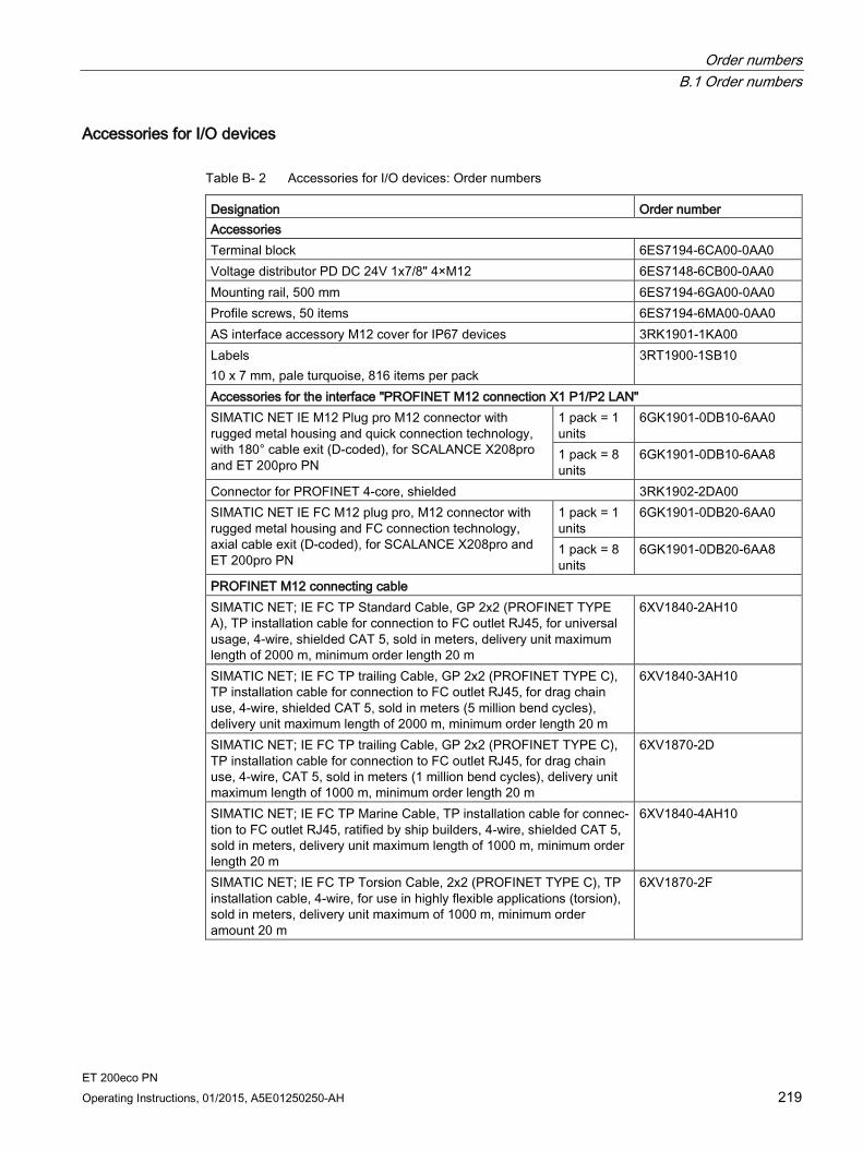
Order numbers B.1 Order numbers
ET 200eco PN Operating Instructions, 01/2015, A5E01250250-AH 219
Accessories for I/O devices
Table B- 2 Accessories for I/O devices: Order numbers
Designation Order number Accessories Terminal block 6ES7194-6CA00-0AA0 Voltage distributor PD DC 24V 1x7/8" 4×M12 6ES7148-6CB00-0AA0 Mounting rail, 500 mm 6ES7194-6GA00-0AA0 Profile screws, 50 items 6ES7194-6MA00-0AA0 AS interface accessory M12 cover for IP67 devices 3RK1901-1KA00 Labels 10 x 7 mm, pale turquoise, 816 items per pack
3RT1900-1SB10
Accessories for the interface "PROFINET M12 connection X1 P1/P2 LAN" SIMATIC NET IE M12 Plug pro M12 connector with rugged metal housing and quick connection technology, with 180° cable exit (D-coded), for SCALANCE X208pro and ET 200pro PN
1 pack = 1 units
6GK1901-0DB10-6AA0
1 pack = 8 units
6GK1901-0DB10-6AA8
Connector for PROFINET 4-core, shielded 3RK1902-2DA00 SIMATIC NET IE FC M12 plug pro, M12 connector with rugged metal housing and FC connection technology, axial cable exit (D-coded), for SCALANCE X208pro and ET 200pro PN
1 pack = 1 units
6GK1901-0DB20-6AA0
1 pack = 8 units
6GK1901-0DB20-6AA8
PROFINET M12 connecting cable SIMATIC NET; IE FC TP Standard Cable, GP 2x2 (PROFINET TYPE A), TP installation cable for connection to FC outlet RJ45, for universal usage, 4-wire, shielded CAT 5, sold in meters, delivery unit maximum length of 2000 m, minimum order length 20 m
6XV1840-2AH10
SIMATIC NET; IE FC TP trailing Cable, GP 2x2 (PROFINET TYPE C), TP installation cable for connection to FC outlet RJ45, for drag chain use, 4-wire, shielded CAT 5, sold in meters (5 million bend cycles), delivery unit maximum length of 2000 m, minimum order length 20 m
6XV1840-3AH10
SIMATIC NET; IE FC TP trailing Cable, GP 2x2 (PROFINET TYPE C), TP installation cable for connection to FC outlet RJ45, for drag chain use, 4-wire, CAT 5, sold in meters (1 million bend cycles), delivery unit maximum length of 1000 m, minimum order length 20 m
6XV1870-2D
SIMATIC NET; IE FC TP Marine Cable, TP installation cable for connec-tion to FC outlet RJ45, ratified by ship builders, 4-wire, shielded CAT 5, sold in meters, delivery unit maximum length of 1000 m, minimum order length 20 m
6XV1840-4AH10
SIMATIC NET; IE FC TP Torsion Cable, 2x2 (PROFINET TYPE C), TP installation cable, 4-wire, for use in highly flexible applications (torsion), sold in meters, delivery unit maximum of 1000 m, minimum order amount 20 m
6XV1870-2F

Order numbers B.1 Order numbers
ET 200eco PN 220 Operating Instructions, 01/2015, A5E01250250-AH
Designation Order number SIMATIC NET, IE Connecting Cable M12-180/M12-180, preassembled IE FC Trailing Cable GP, with 2 x M12 connectors (D-coded)
0.3 m 6XV1870-8AE30 0.5 m 6XV1870-8AE50 1.0 m 6XV1870-8AH10 1.5 m 6XV1870-8AH15 2.0 m 6XV1870-8AH20 3.0 m 6XV1870-8AH30 5.0 m 6XV1870-8AH50 10.0 m 6XV1870-8AN10 15.0 m 6XV1870-8AN15
Bus line for PROFINET, converted on both sides, 4-wire, shielded, converted with 2 x M12 D coded, angled
3.0 m 6RK1902-2NB30 5.0 m 6RK1902-2NB50 10.0 m 6RK1902-2NC10
Bus line for PROFINET, converted on one side, 4-wire, shielded, converted with 1 x M12 D coded
3.0 m 3RK1902-2HB30 3.0 m 3RK1902-2HB50 10.0 m 3RK1902-2HC10
Miscellaneous AS interface accessory M12 sealing cap for IP67 modules 3RX9802-0AA00 Accessory for the interface "M12-socket X1 to X4/X8 Non-converted connector M12 jack, 5-pin, can be pre-assembled, max. 0.75 mm2, screw terminals, type M, NO+NC
3RK19024BA00-5AA0
Angle M12 jack, 5-pin, can be pre-assembled, max. 0.75 mm2, screw terminals, type M,IP67, NO+NC
3RX8000-0CE55
M12 jack, 4-pin, can be assembled, max. 0.75 mm2, screw terminals, type L, IP67, NO+NC
3RX8000-0CD40
M12 plug-in cables, shielded, for connecting digital and analog sensors and actuators
(on request)
Preassembled cable Connecting cable M12-M12, 3-pin, PUR cable, 3 × 0.34 mm2, type E, L, IP67, NO, straight female connector M12 to straight male connector M12
0.6 m 3RX8000-0GF32-1AA6 1.0 m 3RX8000-0GF32-1AB0 1.5 m 3RK19024PB15-3AA0
Connecting cable M12-M12, 4-pin, PUR cable, 4 × 0.34 mm2, type F, L, IP67, NO+NC, straight female connector M12 to straight male connector M12
0.6 m 3RX8000-0GF42-1AA6 1.0 m 3RX8000-0GF42-1AB0 1.5 m 3RX8000-0GF42-1AB5
Angled cable connector M12, 4-pin, 5M PUR line, 4 x 0.34 mm2, type L, IP 67, NO+NC
5.0 m 3RX8000-0CE42-1AF0 10 m 3RX8000-0CE42-1AL0
Angled cable connector M12, 5-pin, PUR line, 5 x 0.34 mm2, type G, IP67, NO+NC
1.5 m 3RX8000-0CE52-1AB5 5.0 m 3RX8000-0CE52-1AF0 10 m 3RX8000-0CE52-1AL0
Unassembled cables Compensation connector M12 with integrated PT1000 for reference junction compensation when connecting thermocouples
6ES7194-4AB00-0AA0

Order numbers B.1 Order numbers
ET 200eco PN Operating Instructions, 01/2015, A5E01250250-AH 221
Designation Order number Y cable SIMATIC DP, Y cable for distributed I/O for double connection of I/O by means of a single cable, 5-pin M12, 200 mm
6ES7194-6KA00-0XA0
Accessories for the interface "DC 24 V IN/OUT M12 (X02/X03)" SIMATIC NET, IE Power M12 Cable Connector pro, connection socket for connecting SCALANCE W-700/X208pro for 24 V DC supply voltage, 4-pin, A-coded, with mounting instructions, 3 items
6GK1907-0DC10-6AA3
SIMATIC NET, IE Power M12 Plug pro, plug connector for connecting Power Supply PS791-1 pro for 24 V DC supply voltage, 4-pin, A-coded, with mounting instructions, 3 items
6GK1907-0DB10-6AA3
Power Connecting Cable M12-180/M12-180 for power supply of the ET 200, presassembled cable with M12 connector and M12 socket, A-coded, 5-pin
0.3 m 6XV1801-5DE30 0.5 m 6XV1801-5DE50 1.0 m 6XV1801-5DH10 1.5 m 6XV1801-5DH15 2.0 m 6XV1801-5DH20 3.0 m 6XV1801-5DH30 5.0 m 6XV1801-5DH50 10.0 m 6XV1801-5DN10 15.0 m 6XV1801-5DN15

Order numbers B.1 Order numbers
ET 200eco PN 222 Operating Instructions, 01/2015, A5E01250250-AH
Accessories for voltage distributors
Table B- 3 Accessories for voltage distributors: Order numbers
Designation Order number Accessories for the interface "DC 24V IN 7/8" (X05)" 7/8" connector with axial cable exit for field assembly ET 200, female insert
6KG19050FB00
24 V socket - 7/8" angled, 5-pin 3RK1902-3DA00 SIMATIC NET, Energy Cable, 5-wire power cable, stranded wire, 5 × 1.5mm2, suitable for cable carriers, delivery unit max. 1000 m, minimum order amount 20 m
6XV1830-8AH10
Power Connecting Cable M12-180/M12-180 for power supply of the ET 200, presassembled cable with M12 connector and M12 socket, A-coded, 5-pin
0.3 m 6XV1801-5DE30
SIMATIC NET, 7/8" connector for power supply of the ET200, preassembled cable with 2 7/8" connectors, 5-pin
1.5 m 6XV1822-5BH15 2.0 m 6XV1822-5BH20 3.0 m 6XV1822-5BH30 5.0 m 6XV1822-5BH50 10.0 m 6XV1822-5BN10 15.0 m 6XV1822-5BN15
Power cable 7/8" for 24 V, switched and non-switched, assem-bled with 2 x 7/8 both sides angled, 1.5 mm2, pin - socket 5-pin
1.5 m (on request) 2.0 m (on request) 3.0 m 3RK1902-3NB30 5.0 m 3RK1902-3NB50 10.0 m 3RK1902-3NC10 15.0 m (on request)
Power cable 7/8" for 24 V, switched and non-switched, assem-bled with 1 x 7/8" one side angled, 1.5 mm2, socket, 5-pin
3.0 m 3RK1902-3GB30 5.0 m 3RK1902-3GB50 10.0 m 3RK1902-3GC10
Spare parts
Table B- 4 Spare parts: Order numbers
Designation Order number Spare fuses for terminal block (miniature copper flat fuse, type FK1, 7.5 A, fast-blow)
6ES7194-6HB00-0AA0
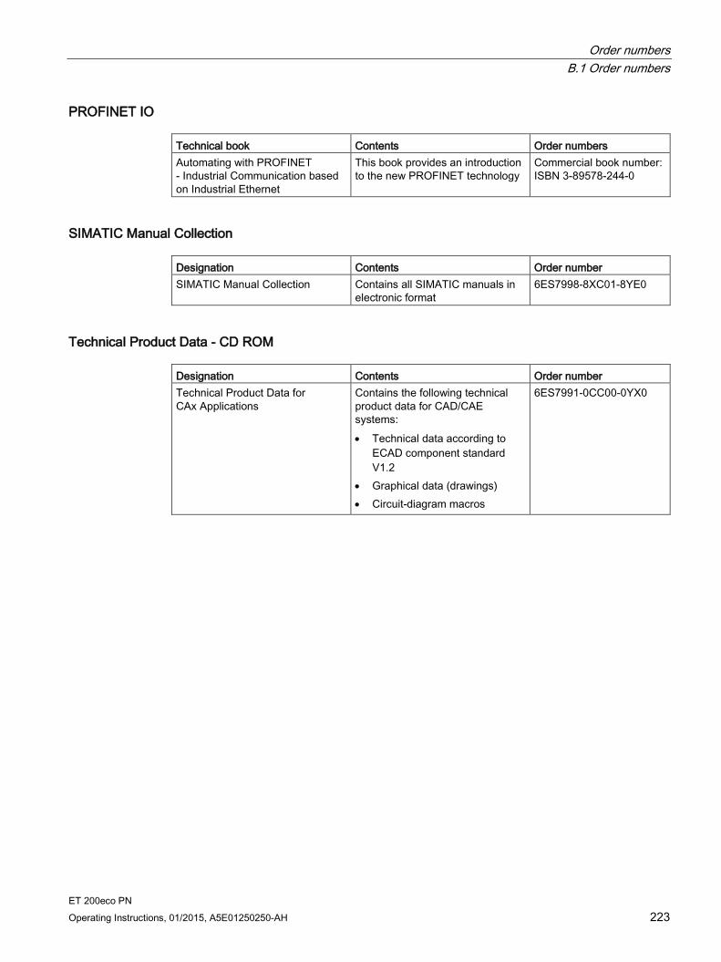
Order numbers B.1 Order numbers
ET 200eco PN Operating Instructions, 01/2015, A5E01250250-AH 223
PROFINET IO Technical book Contents Order numbers Automating with PROFINET - Industrial Communication based on Industrial Ethernet
This book provides an introduction to the new PROFINET technology
Commercial book number: ISBN 3-89578-244-0
SIMATIC Manual Collection Designation Contents Order number SIMATIC Manual Collection Contains all SIMATIC manuals in
electronic format 6ES7998-8XC01-8YE0
Technical Product Data - CD ROM Designation Contents Order number Technical Product Data for CAx Applications
Contains the following technical product data for CAD/CAE systems: • Technical data according to
ECAD component standard V1.2
• Graphical data (drawings) • Circuit-diagram macros
6ES7991-0CC00-0YX0

ET 200eco PN 224 Operating Instructions, 01/2015, A5E01250250-AH
Dimensional drawings C C.1 Dimensional drawings
Dimensional drawing of the I/O devices of 30 mm width The figure shows the dimensional drawing of the I/O devices:
8 DI DC 24V 4×M12
8 DO DC 24V/1,3A 4×M12
8 DO DC 24V/0,5A 4×M12
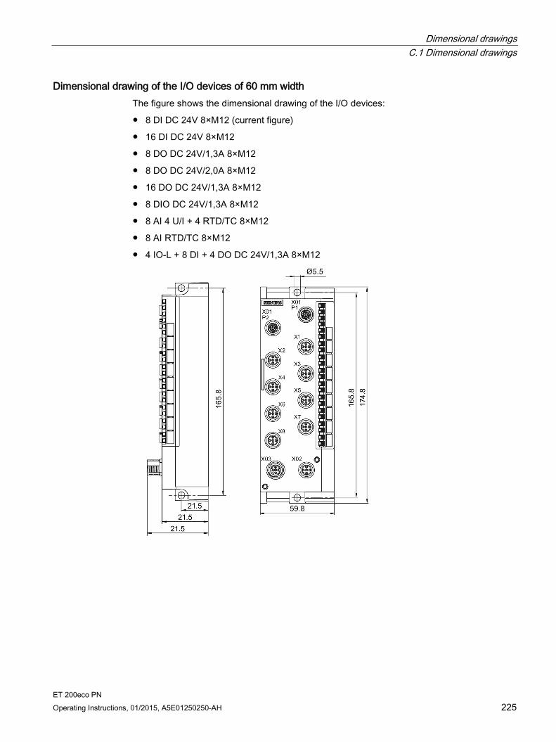
Dimensional drawings C.1 Dimensional drawings
ET 200eco PN Operating Instructions, 01/2015, A5E01250250-AH 225
Dimensional drawing of the I/O devices of 60 mm width The figure shows the dimensional drawing of the I/O devices:
8 DI DC 24V 8×M12 (current figure)
16 DI DC 24V 8×M12
8 DO DC 24V/1,3A 8×M12
8 DO DC 24V/2,0A 8×M12
16 DO DC 24V/1,3A 8×M12
8 DIO DC 24V/1,3A 8×M12
8 AI 4 U/I + 4 RTD/TC 8×M12
8 AI RTD/TC 8×M12
4 IO-L + 8 DI + 4 DO DC 24V/1,3A 8×M12

Dimensional drawings C.1 Dimensional drawings
ET 200eco PN 226 Operating Instructions, 01/2015, A5E01250250-AH
Dimensional drawing of the I/O devices of 60 mm width (with 4 I/O connectors) The figure shows the dimensional drawing of the I/O devices:
4 AO U/I 4×M12

Dimensional drawings C.1 Dimensional drawings
ET 200eco PN Operating Instructions, 01/2015, A5E01250250-AH 227
Dimensional drawing of the voltage distributor The figure shows the dimensional drawing of the voltage distributor PD DC 24V 1×7/8" 4×M12

Dimensional drawings C.1 Dimensional drawings
ET 200eco PN 228 Operating Instructions, 01/2015, A5E01250250-AH
Dimensional drawing of the terminal block The figure shows the dimensional drawing of the terminal block:
Separately
Installed on an I/O device

Dimensional drawings C.1 Dimensional drawings
ET 200eco PN Operating Instructions, 01/2015, A5E01250250-AH 229
Dimensional drawing of the mounting rail The figure shows the dimensional drawing of the mounting rail:
Separately
with an I/O device of 30 mm width
with an I/O device of 60 mm width
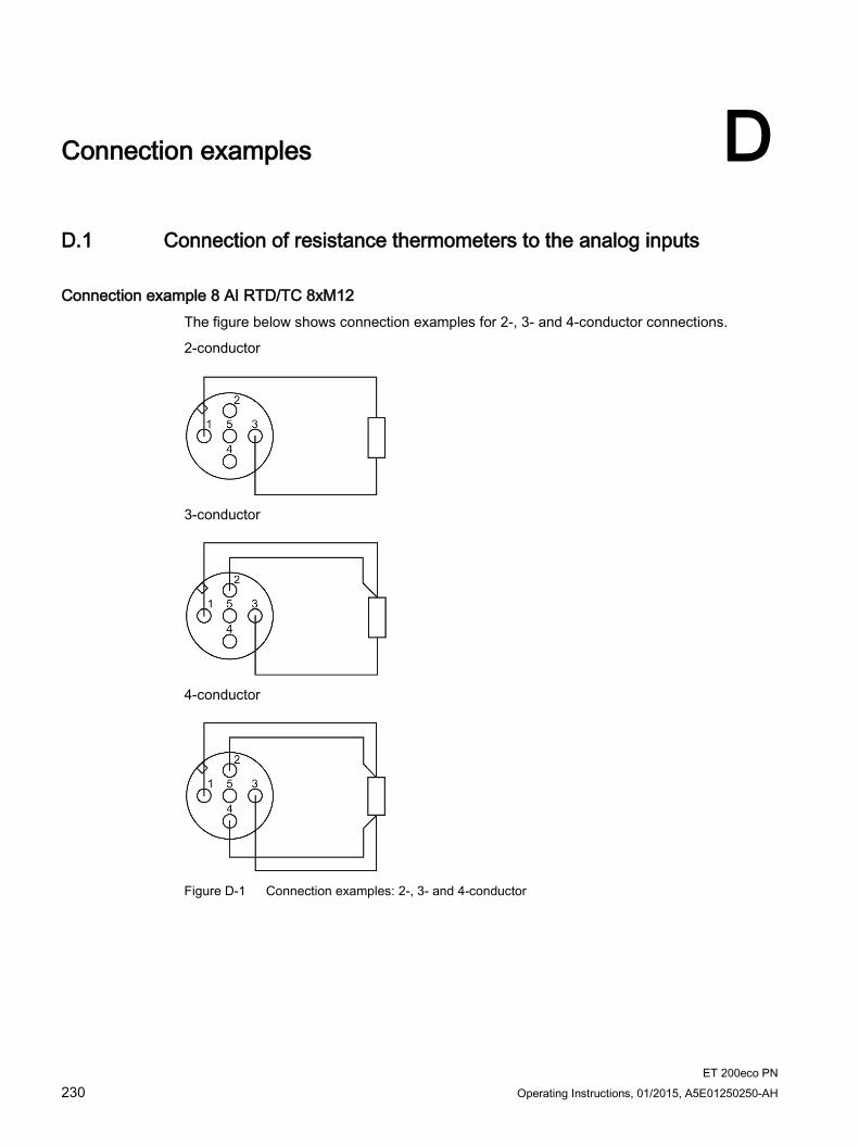
ET 200eco PN 230 Operating Instructions, 01/2015, A5E01250250-AH
Connection examples D D.1 Connection of resistance thermometers to the analog inputs
Connection example 8 AI RTD/TC 8xM12 The figure below shows connection examples for 2-, 3- and 4-conductor connections.
2-conductor
3-conductor
4-conductor
Figure D-1 Connection examples: 2-, 3- and 4-conductor
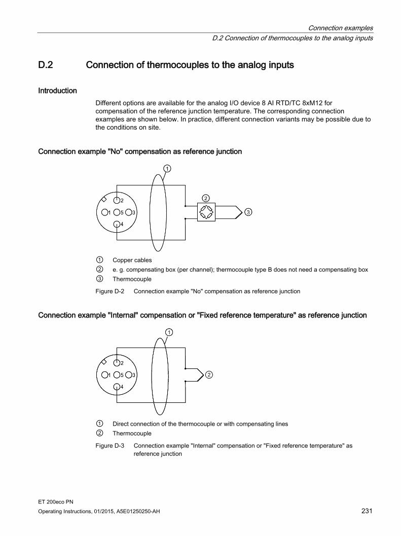
Connection examples D.2 Connection of thermocouples to the analog inputs
ET 200eco PN Operating Instructions, 01/2015, A5E01250250-AH 231
D.2 Connection of thermocouples to the analog inputs
Introduction Different options are available for the analog I/O device 8 AI RTD/TC 8xM12 for compensation of the reference junction temperature. The corresponding connection examples are shown below. In practice, different connection variants may be possible due to the conditions on site.
Connection example "No" compensation as reference junction
① Copper cables ② e. g. compensating box (per channel); thermocouple type B does not need a compensating box ③ Thermocouple
Figure D-2 Connection example "No" compensation as reference junction
Connection example "Internal" compensation or "Fixed reference temperature" as reference junction
① Direct connection of the thermocouple or with compensating lines ② Thermocouple
Figure D-3 Connection example "Internal" compensation or "Fixed reference temperature" as reference junction

Connection examples D.2 Connection of thermocouples to the analog inputs
ET 200eco PN 232 Operating Instructions, 01/2015, A5E01250250-AH
Connection example "RTD (0)" as reference junction With M12 compensation connector (integrated resistance thermometer Pt1000)
① Direct connection of the thermocouple or with compensating lines ② M12 compensation connector (terminals 1 and 3 assigned with internal Pt1000) only on
round socket X1. The comparison value of the M12 compensation connector at round socket X1 also applies to thermocouples at X2, X3, X4, X5, X6, X7 and X8.
③ Thermocouple Figure D-4 Connection example "RTD (0)" as reference junction in M12 compensation connector
With external resistance thermometer Pt1000
① M12 connector only on round socket X1 ② External Pt1000 (α = 0.003851) in the area of the reference junction with copper cables at
terminals 1 and 3. The comparison value of the external Pt1000 at round socket X1 also applies to thermocouples at X2, X3, X4, X5, X6, X7 and X8.
③ Thermocouple Figure D-5 Connection example "RTD (0)" as reference junction with external Pt1000
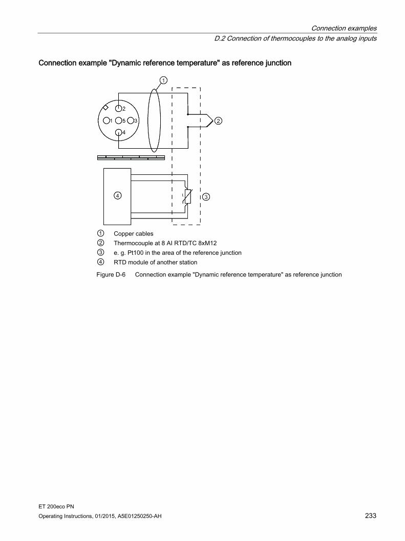
Connection examples D.2 Connection of thermocouples to the analog inputs
ET 200eco PN Operating Instructions, 01/2015, A5E01250250-AH 233
Connection example "Dynamic reference temperature" as reference junction
① Copper cables ② Thermocouple at 8 AI RTD/TC 8xM12 ③ e. g. Pt100 in the area of the reference junction ④ RTD module of another station
Figure D-6 Connection example "Dynamic reference temperature" as reference junction
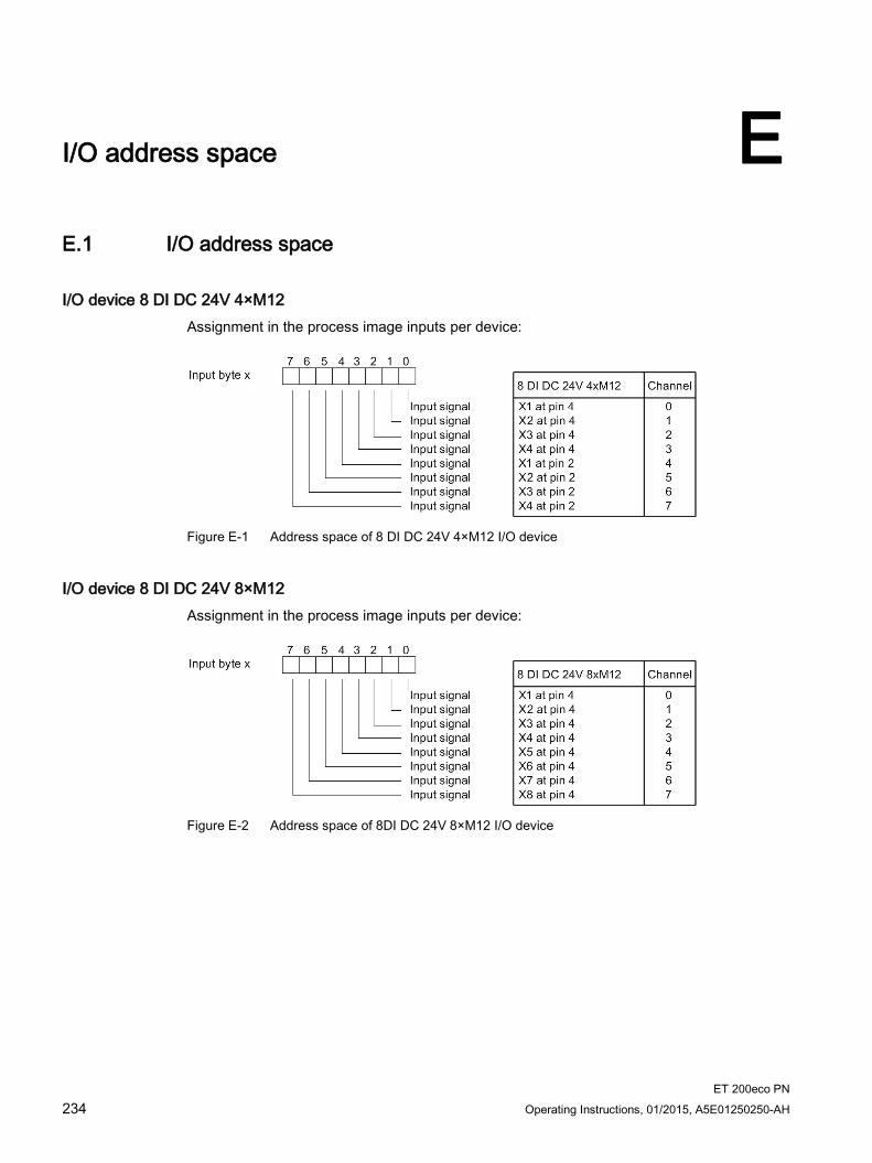
ET 200eco PN 234 Operating Instructions, 01/2015, A5E01250250-AH
I/O address space E E.1 I/O address space
I/O device 8 DI DC 24V 4×M12 Assignment in the process image inputs per device:
Figure E-1 Address space of 8 DI DC 24V 4×M12 I/O device
I/O device 8 DI DC 24V 8×M12 Assignment in the process image inputs per device:
Figure E-2 Address space of 8DI DC 24V 8×M12 I/O device

I/O address space E.1 I/O address space
ET 200eco PN Operating Instructions, 01/2015, A5E01250250-AH 235
I/O device 16 DI DC 24V 8×M12 Assignment in the process image inputs per device:
Figure E-3 Address space of 16 DI DC 24V 8×M12 I/O device
I/O device 8 DO DC 24V/1,3A 4×M12 Assignment in the process image output per device:
Figure E-4 Address space of 8 DO DC 24V/1,3A 4×M12 I/O device

I/O address space E.1 I/O address space
ET 200eco PN 236 Operating Instructions, 01/2015, A5E01250250-AH
I/O device 8 DO DC 24V/0,5A 4×M12 Assignment in the process image output per device:
Figure E-5 Address space of 8 DO DC 24V/0,5A 4×M12 I/O device
I/O device 8 DO DC 24V/1,3A 8×M12 and 8 DO DC 24V/2,0A 8×M12 Assignment in the process image output per device:
Figure E-6 Address space of I/O device 8 DO DC 24V/1,3A 8×M12 and 8 DO DC 24V/2,0A 8×M12

I/O address space E.1 I/O address space
ET 200eco PN Operating Instructions, 01/2015, A5E01250250-AH 237
I/O device 16 DO DC 24V/1,3A 8×M12 Assignment in the process image output per device:
Figure E-7 Address space of 16 DO DC 24V/1,3A 8×M12 I/O device
I/O device 8 DIO DC 24V/1,3A 8×M12 Assignment in the process image inputs per device:
Figure E-8 Address space of 8 DIO DC 24V/1,3A 8×M12 I/O device

I/O address space E.1 I/O address space
ET 200eco PN 238 Operating Instructions, 01/2015, A5E01250250-AH
I/O device 8 AI 4 U/I + 4 RTD/TC 8×M12 Assignment in the process image inputs per device:
Figure E-9 Address space of 8 AI 4 U/I + 4 RTD/TC 8×M12 I/O device
I/O device 8 AI RTD/TC 8×M12 Assignment in the process image inputs per device:
Figure E-10 Address space of 8 AI RTD/TC 8×M12 I/O device

I/O address space E.1 I/O address space
ET 200eco PN Operating Instructions, 01/2015, A5E01250250-AH 239
I/O device 4 AO U/I 4×M12 Assignment in the process image output per device:
Figure E-11 Address space of 4 AO U/I 4×M12 I/O device
IO-Link Master 4 IO-L + 8 DI + 4 DO DC 24V/1,3A 8xM12 During the STEP 7 configuration, you can select the address space according to use.
During GSD configuration, Slot 1 "4 IO-L" has fixed 32 bytes input and 32 bytes output. Addressing of the input and output data can be selected freely using the S7-PCT tool.
Note: By default, the value status (PortQualifier) is disabled. An active value status (PortQualifier) is generally at byte x bit 0 to bit 3. It can also be placed freely within the address range (byte x to x+32).
Assignment of the inputs and IO-Link channels as an example:
Figure E-12 Address space of the IO-Link channels of the IO-Link Master 4 IO-L + 8 DI + 4 DO DC 24V/1,3A 8xM12

I/O address space E.1 I/O address space
ET 200eco PN 240 Operating Instructions, 01/2015, A5E01250250-AH
Slot "8 DI + 4DO" has its own address space. The scope amounts to one byte inputs and one byte outputs.
Figure E-13 Address space of the inputs and outputs of the IO-Link Master 4 IO-L + 8 DI + 4 DO DC 24V/1,3A 8xM12
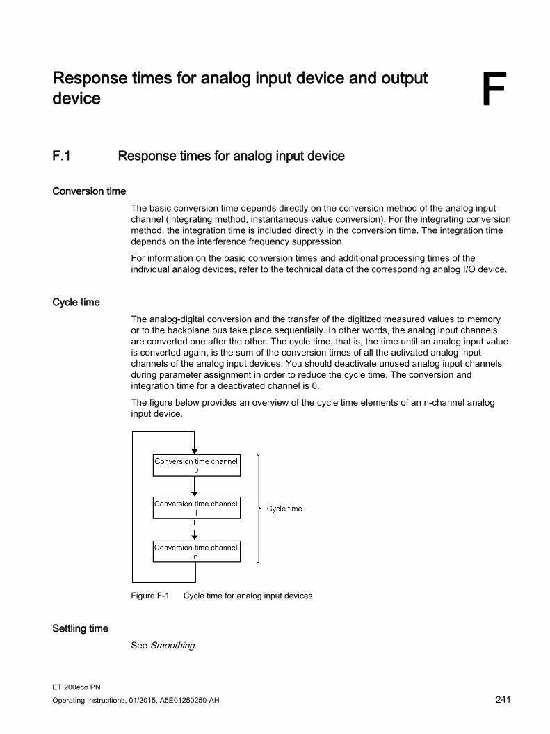
ET 200eco PN Operating Instructions, 01/2015, A5E01250250-AH 241
Response times for analog input device and output device F F.1 Response times for analog input device
Conversion time The basic conversion time depends directly on the conversion method of the analog input channel (integrating method, instantaneous value conversion). For the integrating conversion method, the integration time is included directly in the conversion time. The integration time depends on the interference frequency suppression.
For information on the basic conversion times and additional processing times of the individual analog devices, refer to the technical data of the corresponding analog I/O device.
Cycle time The analog-digital conversion and the transfer of the digitized measured values to memory or to the backplane bus take place sequentially. In other words, the analog input channels are converted one after the other. The cycle time, that is, the time until an analog input value is converted again, is the sum of the conversion times of all the activated analog input channels of the analog input devices. You should deactivate unused analog input channels during parameter assignment in order to reduce the cycle time. The conversion and integration time for a deactivated channel is 0.
The figure below provides an overview of the cycle time elements of an n-channel analog input device.
Figure F-1 Cycle time for analog input devices
Settling time See Smoothing.
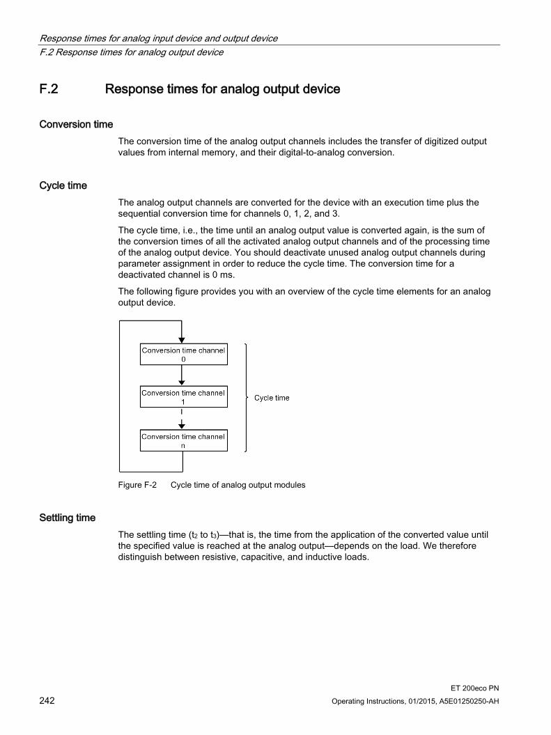
Response times for analog input device and output device F.2 Response times for analog output device
ET 200eco PN 242 Operating Instructions, 01/2015, A5E01250250-AH
F.2 Response times for analog output device
Conversion time The conversion time of the analog output channels includes the transfer of digitized output values from internal memory, and their digital-to-analog conversion.
Cycle time The analog output channels are converted for the device with an execution time plus the sequential conversion time for channels 0, 1, 2, and 3.
The cycle time, i.e., the time until an analog output value is converted again, is the sum of the conversion times of all the activated analog output channels and of the processing time of the analog output device. You should deactivate unused analog output channels during parameter assignment in order to reduce the cycle time. The conversion time for a deactivated channel is 0 ms.
The following figure provides you with an overview of the cycle time elements for an analog output device.
Figure F-2 Cycle time of analog output modules
Settling time The settling time (t2 to t3)—that is, the time from the application of the converted value until the specified value is reached at the analog output—depends on the load. We therefore distinguish between resistive, capacitive, and inductive loads.

Response times for analog input device and output device F.2 Response times for analog output device
ET 200eco PN Operating Instructions, 01/2015, A5E01250250-AH 243
Response time The response time (t1 to t3)—that is, the time from the application of the digital output values in internal memory until the specified value is reached at the analog output—is, in the most unfavorable case, the sum of the cycle time and the settling time. The worst case scenario is when the analog channel has been converted immediately before a new output value is transferred and is not converted again until all other channels have been converted (cycle time).
This figure shows the response time of an analog output channel:
tA Response time tZ Cycle time, corresponding to the processing time of the device and the conversion time of the
channel tE Settling time t1 New digital output value applied t2 Output value transferred and converted t3 Specified output value obtained
Figure F-3 Response time of an analog output channel
ET 200eco PN 244 Operating Instructions, 01/2015, A5E01250250-AH
Fail-safe shutdown of ET 200eco PN standard modules G G.1 Back-up oriented shutdown of ET 200eco PN standard modules
Introduction The following structure describes how you can shutdown ET 200eco PN standard modules in a fail-safe manner.
Through the displayed structure (with the safety shutdown device: for example, 3TK28), all digital outputs that are connected to the supply 2L+ and 2M (24 V switched) from the ET 200eco PN standard modules are switched to the secure OFF state. Here the safety class SIL2/Category 3/PLd is reached.
Principle of operation The higher-level safety shutdown device (e.g. 3TK28) disconnects the supplies 2L+ and 2M switched. The ET 200eco PN standard modules running on the supply 2L+ and 2M (24 V switched) and their digital outputs are switched to the safe state. The digital outputs connected to the supply 1L+ and 1M (24 V non-switched) are not intended for switching under normal operating conditions and cannot be safely shutdown.
There is no opposite influence of the outputs.
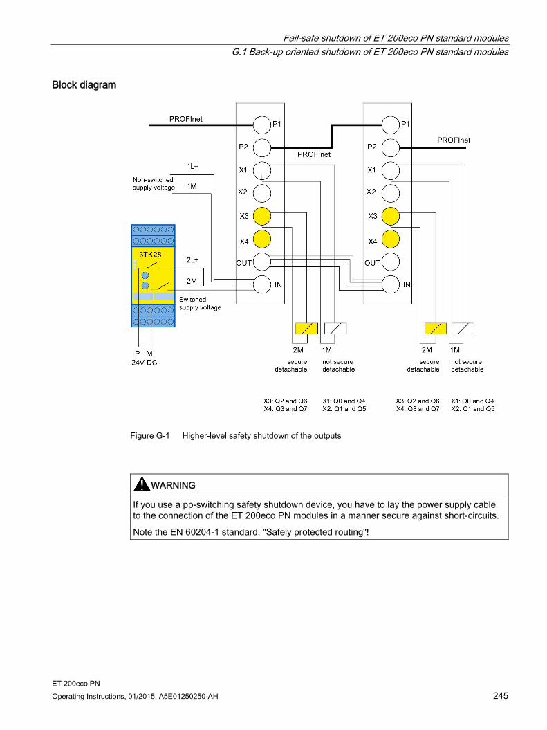
Fail-safe shutdown of ET 200eco PN standard modules G.1 Back-up oriented shutdown of ET 200eco PN standard modules
ET 200eco PN Operating Instructions, 01/2015, A5E01250250-AH 245
Block diagram
Figure G-1 Higher-level safety shutdown of the outputs
WARNING
If you use a pp-switching safety shutdown device, you have to lay the power supply cable to the connection of the ET 200eco PN modules in a manner secure against short-circuits.
Note the EN 60204-1 standard, "Safely protected routing"!

Fail-safe shutdown of ET 200eco PN standard modules G.1 Back-up oriented shutdown of ET 200eco PN standard modules
ET 200eco PN 246 Operating Instructions, 01/2015, A5E01250250-AH
Request TÜV certificate (report no. SA76041 T, revision 1.0 from 03.30.2010) You can request copies of the TÜV certificate and the accompanying report at the following address:
Siemens Aktiengesellschaft Automation Technology Sector I IA AS R&D DH A3 Postfach 1963 D-92209 Amberg

ET 200eco PN Operating Instructions, 01/2015, A5E01250250-AH 247
Glossary
Autonegotiation Configuration protocol in the Fast Ethernet. Before the actual data transmission, the devices on the network agree a transfer mode that each participating device can master (100 Mbps or 10 Mbps, full-duplex or half-duplex).
Bus Data transfer bus to which all nodes are connected. It has two defined ends.
ET 200 features a 2-wire bus.
Bus connector Physical connection between the bus node and the bus cable.
Chassis ground Chassis ground includes all the interconnected inactive parts of equipment that must not carry a hazardous voltage even in the event of a fault.
Device name Because a fixed IP address is assigned to the device name, an IO Device must have a device name in order to be addressed by an IO Controller. With PROFINET, this procedure is used because names are easier to handle than complex IP addresses.
The assignment of a device name for a specific IO Device can be compared with the setting of the PROFIBUS address for a DP slave.
In the state of delivery a IO Device has no device name. The IO Device can only be addressed for an IO Controller after the device has been assigned a device name with the IO Supervisor/PC, for the transfer of configuration data (IP address and other data) during startup or for the exchange of user data in cyclic operation, for example.

Glossary
ET 200eco PN 248 Operating Instructions, 01/2015, A5E01250250-AH
Device replacement without removable media/programming device IO Devices having this function can be replaced easily:
A removable medium (such as SIMATIC Memory Card) on which the device name is stored is not required.
The device name does not have to be assigned using the programming device.
Instead of being assigned a device name from the removable medium or programming device, the IO Device is now assigned a device name by the IO Controller.
The IO Controller uses the configured topology and the correlations derived from the IO Devices. The configured target topology must agree with the actual topology.
Diagnostics The detection, localization, classification, visualization and further evaluation of errors, disturbances and messages.
Provides monitoring functions which are executed automatically when the system is in RUN. Increases plant availability by reducing commissioning times and down times.
Distributed I/O systems I/O systems that are not integrated into the central CPU rack, but rather at distributed remote locations. Example:
ET 200M, ET 200X, ET 200L, ET 200S, ET 200 SP, ET 200pro, ET 200eco PN
DP/AS-I Link
S5-95U with PROFIBUS-DP slave interface
Further DP slaves supplied by Siemens or other vendors.
Electrically isolated The reference potentials of the control and load circuit of isolated I/O modules are electrically isolated, for example, by means of optocoupler, relay or transformer. I/O circuits may be connected to the same potential.
Equipotential bonding Electrical connection (equipotential bonding conductor) that keeps electrical equipment and extraneous conductive objects to the same or almost the same potential in order to prevent disturbing or dangerous voltages between those objects.
Fast Ethernet Fast Ethernet describes the standard for transferring data with 100 Mbps. This transfer technology used the 100 Base-T standard for this.

Glossary
ET 200eco PN Operating Instructions, 01/2015, A5E01250250-AH 249
Grounding Refers to the bonding of conductive elements to ground via a grounding system.
GSD file The properties of a PROFINET device are described in a GSD (Generic Station Description) file, which contains all required information for the configuration.
As with PROFIBUS, you can link a PROFINET device in STEP 7 by means of a GSD file.
In PROFINET IO, the GSD file is in XML format. The structure corresponds to ISO 15734, the worldwide standard for device descriptions.
Industrial Ethernet Industrial Ethernet (previously SINEC H1) is a technology that allows data to be transferred fail-safe in an industrial environment.
Standard Ethernet components can be used since PROFINET is an open system. However, we recommend setting up PROFINET as Industrial Ethernet.
Non-isolated The reference potentials of the control and load circuit of non-isolated I/O modules are electrically interconnected.
Parameter assignment The term parameterization denotes the transfer of parameters from the IO Controller to the IO Device.
PELV Protective Extra Low Voltage = extra low voltage with safe isolation
Prioritized startup Prioritized startup (FSU) denotes PROFINET functionality for accelerating the startup of IO Devices for RT and IRT communication within a PROFINET IO system.
The functions reduce the time that the correspondingly configured IO Devices require to recover the cyclic exchange of user data in the following situations:
After power has returned
After station recovery
After activation of IO Devices

Glossary
ET 200eco PN 250 Operating Instructions, 01/2015, A5E01250250-AH
PROFIBUS International Technical committee dedicated to the definition and development of the PROFIBUS and PROFINET standard.
Also known as the PROFIBUS Trade Organization (PTO).
Homepage: www.profibus.com
PROFINET Within the framework of Totally Integrated Automation (TIA), PROFINET represents a consequent enhancement of:
PROFIBUS DP, the established field bus, and
Industrial Ethernet, the communication bus for the cell level.
Experience gained from both systems was and is being integrated into PROFINET.
PROFINET is an Ethernet-based automation standard of PROFIBUS International (previouslyPROFIBUS Trade Organization) and defines a multi-vendor communication, automation and engineering model. Since 2003, PROFINET has been part of IEC 61158.
See PROFIBUS International
PROFINET component A PROFINET component encompasses the entire data of the hardware configuration, the parameters of the modules, and the corresponding user program. The PROFINET component is composed of:
Technological function
The (optional) technological (software) function includes the interface to other PROFINET components in the form of interconnectable inputs and outputs.
Device
The device is the representation of the physical automation device or field device including the IO devices, sensors, actuators, mechanics, and device firmware.
PROFINET Device All PROFINET devices are equipped with at least one Industrial Ethernet port. A PROFINET device can also have a PROFIBUS connection (master with proxy functionality).
Glossary
ET 200eco PN Operating Instructions, 01/2015, A5E01250250-AH 251
PROFINET IO Within the framework of PROFINET, PROFINET IO represents a communication concept for the implementation of modular, distributed applications.
PROFINET IO allows you to create automation solutions, which are familiar to you from PROFIBUS.
Implementation of PROFINET IO is effected on the one hand by means of the PROFINET standard for automation devices and on the other by means of the STEP 7 engineering tool. This means you have the same application view in STEP 7 regardless of whether you are configuring PROFINET devices or PROFIBUS devices. Programming your user program is essentially the same for PROFINET IO and PROFIBUS DP if you use the extended blocks and system status lists for PROFINET IO.
PROFINET IO Controller Device used to address connected IO Devices. That means: the IO Controller exchanges input and output signals with assigned field devices. The IO Controller is usually the controller running the automation program.
PROFINET IO Device Distributed field device which is assigned to one of the IO Controllers (remote IO, valve blocks, frequency converters, switches).
Reference potential Reference potential for the evaluation / measuring of the voltages of participating circuits.
SELV Safety Extra Low Voltage
SNMP SNMP (Simple Network Management Protocol) is the standardized protocol for diagnostics and parameter assignment of the Ethernet network infrastructure.
In the office area and in automation technology, devices support a wide range of manufacturers on the Ethernet SNMP.
SNMP-based applications can be operated parallel to applications with PROFINET on the same network.
The scope of the supported functions varies depending on the device type. A switch, for example, has more functions than a CP 1616.
Glossary
ET 200eco PN 252 Operating Instructions, 01/2015, A5E01250250-AH
Switch PROFIBUS is based on a line topology. Communication nodes are interconnected by means of a passive line, namely the bus.
By contrast, the Industrial Ethernet consists of point-to-point connections: Each communication node is interconnected directly with one other communication node.
If a communication node is to be interconnected with several other communication nodes, this communication node is connected to the port of an active network component, i.e., the switch. Other communications nodes (including switches) can then be connected to the other ports of the switch. The connection between a communication node and the switch remains a point-to-point connection.
The task of a switch is thus to regenerate and distribute received signals. The switch "learns" the Ethernet address(es) of a connected PROFINET device or of other switches and passes only the signals intended for the connected PROFINET device or switch.
A switch has a certain number of ports. Connect a maximum of one PROFINET device or one additional switch to each port.
Total current Total current of all output channels of a digital output module.
ET 200eco PN Operating Instructions, 01/2015, A5E01250250-AH 253
Index
1 16 DI DC 24V 8×M12
Block diagram, 110 Parameters, 114 Pin assignment, 110 Properties, 109 Technical data, 111
16 DO DC 24V/1,3A 8×M12 Block diagram, 136 Parameters, 141 Pin assignment, 135 Properties, 135 Technical data, 137
2 24 V DC supply, 28
4 4 AO U/I 4×M12
Block diagram, 201 Pin assignment, 201 Properties, 200 Technical data, 202
4 AO U/I 4xM12 Parameters, 206
4 IO-L + 8 DI + 4 DO DC 24V/1,3A 8×M12 Block diagram, 150 Parameter, 155 Pin assignment, 149 Properties, 148 Technical data, 151
8 8 AI 4 U/I + 4 RTD/TC 8×M12
Block diagram, 162 Pin assignment, 160 Properties, 159 Technical data, 163
8 AI 4 U/I + 4 RTD/TC 8xM12 Parameters, 175
8 AI RTD/TC 8xM12 Block diagram, 170
Parameters, 178 Pin assignment, 169 Properties, 168 Technical data, 171
8 DI DC 24V 4×M12 Block diagram, 102 Parameters, 114 Pin assignment, 102 Properties, 101 Technical data, 103
8 DI DC 24V 8×M12 Block diagram, 106 Parameters, 114 Pin assignment, 106 Properties, 105 Technical data, 107
8 DIO DC 24V/1,3A 8×M12 Block diagram, 143 Parameters, 147 Pin assignment, 143 Properties, 142 Technical data, 144
8 DO DC 24V/0,5A 4×M12 Block diagram, 121 Parameters, 140 Pin assignment, 121 Properties, 120 Technical data, 122
8 DO DC 24V/1,3A 4×M12 Block diagram, 117 Parameters, 140 Pin assignment, 116 Properties, 115 Technical data, 118
8 DO DC 24V/1,3A 8×M12 Block diagram, 126 Parameters, 140 Pin assignment, 125 Properties, 125 Technical data, 127
8 DO DC 24V/2,0A 8×M12 Block diagram, 131 Parameters, 140 Pin assignment, 130 Properties, 130 Technical data, 132
Index
ET 200eco PN 254 Operating Instructions, 01/2015, A5E01250250-AH
A Additional support, 4 Analog value, 187
B Basic conversion time, 241 Basic knowledge, 3 Burst pulses, 94
C CE marking, 92 Climatic environmental conditions, 96 Commissioning
ET 200eco PN, 74 Components and protective measures, 30 Components of ET 200eco PN, 13 Configuring
ET 200eco PN, 65 IO-Link Master I/O device, 66
Continuous shock, 98, 98 Conversion time, 241, 242 Cycle time, 241, 242
D Definition
Electromagnetic compatibility, 94 Device identification, 68 Device replacement without programming device, 71 Diagnostics, 87
After IO Controller STOP, 91 After recovery of the IO Device, 91
Diagnostics messages PROFINET IO, 87
Dimensional drawing, 224 Disposal, 4 Distributed I/O systems – application area, 10
E Electrical isolation
between..., 32 Electromagnetic compatibility, 94 Electrostatic discharge, 94 EMC, 94 EMERGENCY-STOP equipment, 28 Emission of radio interference, 95 Error classes for the I/O devices, 89
ET 200eco PN Commissioning, 74 Components, 13 LED display, 82 Operation with grounded infeed, 29
ET 200eco PN distributed I/O device Definition, 12 Field of application, 12 IO Controller, 18
ET 200eco PN standard modules Fail-safe shutdown, 244
Evaluating interrupts using an IO Controller, 80 Exchange object, 79
F Firmware update
Online, 78 Flash test, 68 Functional earth (FE), 34
G General rules
For operation of an ET 200eco PN, 28 Grounded infeed, 29 GSDML file (PROFINET IO), 65 Guide, 4
H HW Config, 65, 69
I I/O address space, 234, 234 I/O device
Wiring, 36 I/O devices
Accessories, 219 IEC 204, 28 IEC 61131, 92 Installing, 19 Insulation test, 100 IO Controller
ET 200eco PN distributed I/O device, 18 IO Controller STOP
Diagnostics events triggered, 91 IO Device, 68
Index
ET 200eco PN Operating Instructions, 01/2015, A5E01250250-AH 255
IO-Link Master Functions, 157
IP address, 68 Isochronous real-time communication, 70
L Labels, 26 LED display
ET 200eco PN, 82 IO-Link Master I/O device, 84 Voltage distributor, 86
Loop-through of PROFINET, 64 of the supply voltage, 64
M M12 connector
connection, 36 Maintenance interrupts, 81 Manual
Purpose, 3 Measuring range
Current, 189, 190 Voltage, 188, 188, 209
Measuring ranges with SIMATIC S7, 187 Mechanical environmental conditions, 98 Media redundancy, 72 Mounting dimensions, 23 Mounting position, 23
O Order numbers, 218 Outdoors, 99 Overall configuration on TN-S system, 31
P Parameter, 140, 155 Parameters, 114, 147, 175, 178, 206
16 DI DC 24V 8×M12, 114 16 DO DC 24V/1,3A 8×M12, 141 4 AO U/I 4xM12, 206 4 IO-L + 8 DI + 4 DO DC 24V/1,3A 8×M12, 155 8 AI 4 U/I + 4 RTD/TC 8xM12, 175 8 AI RTD/TC 8xM12, 178 8 DI DC 24V 4×M12, 114 8 DI DC 24V 8×M12, 114
8 DIO DC 24V/1,3A 8×M12, 147 8 DO DC 24V/0,5A 4×M12, 140 8 DO DC 24V/1,3A 4×M12, 140 8 DO DC 24V/1,3A 8×M12, 140
PD DC 24V 1×7/8, Pin assignment
16 DI DC 24V 8xM12, 43 16 DO DC 24V/1,3A 8×M12, 47 4 AO U/I 4×M12, 57 4 IO-L + 8 DI + 4 DO DC 24V/1,3A 8×M12, 49 8 AI 4 U/I + 4 RTD/TC 8×M12, 51 8 AI RTD/TC 8×M12, 54 8 DI DC 24V 4×M12, 42 8 DI DC 24V 8xM12, 42 8 DIO DC 24V/1,3A 8×M12, 48 8 DO DC 24V/0,5A 4×M12, 45 8 DO DC 24V/1,3A 4×M12, 44 8 DO DC 24V/1,3A 8×M12, 46 8 DO DC 24V/2,0A 8×M12, 46 For loop-through of the supply voltage, 41 For supply voltage infeed, 40 Of the terminal block, 61 PROFINET connector, 39 Voltage distributor PD DC 24V 1x7/8, 63
Pollution degree, 100 Port, 69 Prioritized startup, 71 PROFINET IO, 10
Network topology, 11 PROFINET IO Device, 68 PROFINET IO standard, 92 Protection against external electrical interference, 29 Protection class, 100 Pulse-shaped disturbances, 94
R Rated voltage, 100 Readers of this manual, 4 Reading diagnostics data, 87 Recovery of the IO Device
Diagnostics events triggered, 91 Recycling, 4 Regulations
For operation of an ET 200eco PN, 28 Removing, 27 Replacing the fuse
Terminal block, 76 Representation of analog values, 192, 192, 193, 193 Resetting to factory settings, 72 Response time, 243
Index
ET 200eco PN 256 Operating Instructions, 01/2015, A5E01250250-AH
S Safe electrical isolation, 29, 30 Safety shutdown device, 244 Scope of information, 4 Scope of this manual, 3 SELV/PELV, 29 Settling time, 242 Shipping conditions, 94 Shock, 98 Signal names, 217 SIMATIC Manual Collection, 223 Sinusoidal disturbance variables, 95 Smoothing, 183 SNMP, 73 Standards and certifications, 92 Status display 24 V DC, 84 STEP 7, 87 Storage conditions, 94 System startup after specific events, 28
T Technical data
Climatic environmental conditions, 96 Electromagnetic compatibility, 94 I/O device 16 DI DC 24V 8×M12, 111 I/O device 16 DO DC 24V/1,3A 8×M12, 137 I/O device 8 DI DC 24V 4×M12, 103 I/O device 8 DI DC 24V 8×M12, 107 I/O device 8 DIO DC 24V/1,3A 8×M12, 144 I/O device 8 DO DC 24V/0,5A 4×M12, 122 I/O device 8 DO DC 24V/1,3A 4×M12, 118 I/O device 8 DO DC 24V/1,3A 8×M12, 127 I/O device 8 DO DC 24V/2,0A 8×M12, 132 Shipping and storage conditions, 94
Technical Support, 5 Temperature, 95 Temperature coefficient, 182 Terminal block
Block diagram, 213 Pin assignment, 212 Properties, 212 Technical data, 213
Test voltage, 100 TN-S system, 31 TÜV certificate, 246
V Vibration, 98
W Wiring
For operation of an ET 200eco PN, 28
Y Y cable, 37