ESXi 4.1 server configuration guide - vmware.com€¦ · 6 Networking Best Practices, Scenarios,...
220
ESXi Configuration Guide ESXi 4.1 vCenter Server 4.1 This document supports the version of each product listed and supports all subsequent versions until the document is replaced by a new edition. To check for more recent editions of this document, see http://www.vmware.com/support/pubs. EN-000327-07
Transcript of ESXi 4.1 server configuration guide - vmware.com€¦ · 6 Networking Best Practices, Scenarios,...

ESXi Configuration GuideESXi 4.1
vCenter Server 4.1
This document supports the version of each product listed andsupports all subsequent versions until the document is replacedby a new edition. To check for more recent editions of thisdocument, see http://www.vmware.com/support/pubs.
EN-000327-07
ESXi Configuration Guide
2 VMware, Inc.
You can find the most up-to-date technical documentation on the VMware Web site at:
http://www.vmware.com/support/
The VMware Web site also provides the latest product updates.
If you have comments about this documentation, submit your feedback to:
Copyright © 2009–2011 VMware, Inc. All rights reserved. This product is protected by U.S. and international copyright andintellectual property laws. VMware products are covered by one or more patents listed at http://www.vmware.com/go/patents.
VMware is a registered trademark or trademark of VMware, Inc. in the United States and/or other jurisdictions. All other marksand names mentioned herein may be trademarks of their respective companies.
VMware, Inc.3401 Hillview Ave.Palo Alto, CA 94304www.vmware.com

Contents
Updated Information 7
About This Book 9
1 Introduction to ESXi Configuration 11
Networking
2 Introduction to Networking 15Networking Concepts Overview 15Network Services 16View Networking Information in the vSphere Client 16View Network Adapter Information in the vSphere Client 17
3 Basic Networking with vNetwork Standard Switches 19
vNetwork Standard Switches 19Port Groups 20Port Group Configuration for Virtual Machines 20VMkernel Networking Configuration 21vNetwork Standard Switch Properties 24
4 Basic Networking with vNetwork Distributed Switches 27
vNetwork Distributed Switch Architecture 28Configuring a vNetwork Distributed Switch 28dvPort Groups 32dvPorts 33Private VLANs 34Configuring vNetwork Distributed Switch Network Adapters 36Configuring Virtual Machine Networking on a vNetwork Distributed Switch 39Network I/O Control 40
5 Advanced Networking 43
Internet Protocol Version 6 43VLAN Configuration 44Networking Policies 44Change the DNS and Routing Configuration 58MAC Addresses 59TCP Segmentation Offload and Jumbo Frames 60NetQueue and Networking Performance 63VMDirectPath I/O 63
VMware, Inc. 3

6 Networking Best Practices, Scenarios, and Troubleshooting 65
Networking Best Practices 65Mounting NFS Volumes 66Networking Configuration for Software iSCSI and Dependent Hardware iSCSI 66Troubleshooting 69
Storage
7 Introduction to Storage 73About ESXi Storage 73Types of Physical Storage 74Supported Storage Adapters 75Target and Device Representations 75About ESXi Datastores 77Comparing Types of Storage 80Displaying Storage Adapters 81Viewing Storage Devices 82Displaying Datastores 83
8 Configuring ESXi Storage 85
Local SCSI Storage 85Fibre Channel Storage 86iSCSI Storage 86Datastore Refresh and Storage Rescan Operations 99Create VMFS Datastores 100Network Attached Storage 101Creating a Diagnostic Partition 103
9 Managing Storage 105
Managing Datastores 105Changing VMFS Datastore Properties 107Managing Duplicate VMFS Datastores 109Using Multipathing with ESXi 111Storage Hardware Acceleration 119Thin Provisioning 120Turn off vCenter Server Storage Filters 123
10 Raw Device Mapping 125
About Raw Device Mapping 125Raw Device Mapping Characteristics 128Managing Mapped LUNs 130
Security
11 Security for ESXi Systems 135ESXi Architecture and Security Features 135
ESXi Configuration Guide
4 VMware, Inc.

Security Resources and Information 141
12 Securing an ESXi Configuration 143
Securing the Network with Firewalls 143Securing Virtual Machines with VLANs 149Securing Virtual Switch Ports 154Internet Protocol Security 155Securing iSCSI Storage 159
13 Authentication and User Management 163
Securing ESXi Through Authentication and Permissions 163About Users, Groups, Permissions, and Roles 164Working with Users and Groups on ESXi Hosts 168Encryption and Security Certificates for ESXi 173
14 Security Best Practices and Scenarios 181
Security Approaches for Common ESXi Deployments 181ESXi Lockdown Mode 184Virtual Machine Recommendations 187
Host Profiles
15 Managing Host Profiles 195Host Profiles Usage Model 195Access Host Profiles View 196Creating a Host Profile 196Export a Host Profile 197Import a Host Profile 197Edit a Host Profile 198Manage Profiles 199Checking Compliance 202
Appendix
Appendix: ESXi Technical Support Commands 207
Index 211
Contents
VMware, Inc. 5

ESXi Configuration Guide
6 VMware, Inc.

Updated Information
This ESXi Configuration Guide is updated with each release of the product or when necessary.
This table provides the update history of the ESXi Configuration Guide.
Revision Description
EN-000327-07 Modified a word in “Set Up CHAP Credentials for a Target,” on page 96.
EN-000327-06 Modified a word in “Handling Datastore Over-Subscription,” on page 122
EN-000327-05 Modified a step in “Create a Jumbo Frames-Enabled VMkernel Interface,” on page 62.
EN-000327-04 n Updated procedure in “Generate New Certificates for the ESXi Host,” on page 174.n Updated procedure in “Replace a Default Certificate with a CA-Signed Certificate,” on page 174.n Updated procedure in “Upload a Certificate and Key Using a HTTPS PUT,” on page 174.n Updated procedure in “Security and the Virtualization Layer,” on page 136
EN-000327-03 n Modified Step 2 in “Configure a Host to Use a Directory Service,” on page 171.n Changed the commands in Step 2 and Step 9 of “Configure SSL Timeouts,” on page 175.
EN-000327-02 In “Comparing Types of Storage,” on page 80 removed VM Cluster from supported vSphere features, andincluded citation for Microsoft clustering.
EN-000327-01 Minor revisions.
EN-000327-00 Initial release.
VMware, Inc. 7

ESXi Configuration Guide
8 VMware, Inc.

About This Book
This manual, the ESXiConfiguration Guide, provides information on how to configure networking forVMware® ESXi, including how to create virtual switches and ports and how to set up networking for virtualmachines, VMware vMotion™, and IP storage. It also discusses configuring the file system and various typesof storage such as iSCSI and Fibre Channel. The guide provides a discussion of security features built intoESXi and the measures that you can take to safeguard ESXi from attack. In addition, it includes a list of ESXitechnical support commands along with their VMware vSphere™ Client equivalents and a description of thevmkfstools utility.
This information covers ESXi 4.1.
Intended AudienceThis manual is intended for anyone who needs to install, upgrade, or use ESXi. The information in this manualis written for experienced Windows or Linux system administrators who are familiar with virtual machinetechnology and datacenter operations.
VMware Technical Publications GlossaryVMware Technical Publications provides a glossary of terms that might be unfamiliar to you. For definitionsof terms as they are used in VMware technical documentation, go to http://www.vmware.com/support/pubs.
Document FeedbackVMware welcomes your suggestions for improving our documentation. If you have comments, send yourfeedback to [email protected].
VMware vSphere DocumentationThe vSphere documentation consists of the combined VMware vCenter Server and ESXi documentation set.
Abbreviations Used in FiguresThe figures in this manual use the abbreviations listed in Table 1.
Table 1. Abbreviations
Abbreviation Description
database vCenter Server database
datastore Storage for the managed host
dsk# Storage disk for the managed host
VMware, Inc. 9

Table 1. Abbreviations (Continued)
Abbreviation Description
hostn vCenter Server managed hosts
SAN Storage Area Network type datastore shared betweenmanaged hosts
tmplt Template
user# User with access permissions
VC vCenter Server
VM# Virtual machines on a managed host
Technical Support and Education ResourcesThe following technical support resources are available to you. To access the current version of this book andother books, go to http://www.vmware.com/support/pubs.
Online and TelephoneSupport
To use online support to submit technical support requests, view your productand contract information, and register your products, go to http://www.vmware.com/support.
Customers with appropriate support contracts should use telephone supportfor the fastest response on priority 1 issues. Go to http://www.vmware.com/support/phone_support.html.
Support Offerings To find out how VMware support offerings can help meet your business needs,go to http://www.vmware.com/support/services.
VMware ProfessionalServices
VMware Education Services courses offer extensive hands-on labs, case studyexamples, and course materials designed to be used as on-the-job referencetools. Courses are available onsite, in the classroom, and live online. For onsitepilot programs and implementation best practices, VMware ConsultingServices provides offerings to help you assess, plan, build, and manage yourvirtual environment. To access information about education classes,certification programs, and consulting services, go to http://www.vmware.com/services.
ESXi Configuration Guide
10 VMware, Inc.
Introduction to ESXi Configuration 1This guide describes the tasks you need to complete to configure ESXi host networking, storage, and security.In addition, it provides overviews, recommendations, and conceptual discussions to help you understand thesetasks and how to deploy a host to meet your needs.
Before you use this information, read the Introduction to vSphere for an overview of system architecture and thephysical and virtual devices that make up a vSphere system.
This introduction summarizes the contents of this guide.
NetworkingThe networking information provides you with a conceptual understanding of physical and virtual networkconcepts, a description of the basic tasks you need to complete to configure your ESXi host’s networkconnections, and a discussion of advanced networking topics and tasks.
StorageThe storage information provides you with a basic understanding of storage, a description of the basic tasksyou perform to configure and manage your ESXi host’s storage, and a discussion of how to set up raw devicemapping (RDM).
SecurityThe security information discusses safeguards that VMware has built into ESXi and measures that you cantake to protect your host from security threats. These measures include using firewalls, taking advantage ofthe security features of virtual switches, and setting up user authentication and permissions.
Host ProfilesThis section describes the host profiles feature and how it is used to encapsulate the configuration of a hostinto a host profile. This section also describes how to apply this host profile to another host or cluster, edit aprofile, and check a host’s compliance with a profile.
VMware, Inc. 11

ESXi Configuration Guide
12 VMware, Inc.
Networking
VMware, Inc. 13

ESXi Configuration Guide
14 VMware, Inc.

Introduction to Networking 2The basic concepts of ESXi networking and how to set up and configure a network in a vSphere environmentare discussed.
This chapter includes the following topics:
n “Networking Concepts Overview,” on page 15
n “Network Services,” on page 16
n “View Networking Information in the vSphere Client,” on page 16
n “View Network Adapter Information in the vSphere Client,” on page 17
Networking Concepts OverviewA few concepts are essential for a thorough understanding of virtual networking. If you are new to ESXi, it ishelpful to review these concepts.
A physical network is a network of physical machines that are connected so that they can send data to andreceive data from each other. VMware ESXi runs on a physical machine.
A virtual network is a network of virtual machines running on a single physical machine that are connectedlogically to each other so that they can send data to and receive data from each other. Virtual machines can beconnected to the virtual networks that you create when you add a network.
A physical Ethernet switch manages network traffic between machines on the physical network. A switch hasmultiple ports, each of which can be connected to a single machine or another switch on the network. Eachport can be configured to behave in certain ways depending on the needs of the machine connected to it. Theswitch learns which hosts are connected to which of its ports and uses that information to forward traffic tothe correct physical machines. Switches are the core of a physical network. Multiple switches can be connectedtogether to form larger networks.
A virtual switch, vSwitch, works much like a physical Ethernet switch. It detects which virtual machines arelogically connected to each of its virtual ports and uses that information to forward traffic to the correct virtualmachines. A vSwitch can be connected to physical switches by using physical Ethernet adapters, also referredto as uplink adapters, to join virtual networks with physical networks. This type of connection is similar toconnecting physical switches together to create a larger network. Even though a vSwitch works much like aphysical switch, it does not have some of the advanced functionality of a physical switch.
A vNetwork Distributed Switch acts as a single vSwitch across all associated hosts on a datacenter. This allowsvirtual machines to maintain consistent network configuration as they migrate across multiple hosts.
A port group specifies port configuration options such as bandwidth limitations and VLAN tagging policiesfor each member port. Network services connect to vSwitches through port groups. Port groups define how aconnection is made through the vSwitch to the network. Typically, a single vSwitch is associated with one ormore port groups.
VMware, Inc. 15

A dvPort group is a port group associated with a vNetwork Distributed Switch and specifies port configurationoptions for each member port. dvPort Groups define how a connection is made through the vNetworkDistributed Switch to the network.
NIC teaming occurs when multiple uplink adapters are associated with a single vSwitch to form a team. Ateam can either share the load of traffic between physical and virtual networks among some or all of itsmembers, or provide passive failover in the event of a hardware failure or a network outage.
VLANs enable a single physical LAN segment to be further segmented so that groups of ports are isolatedfrom one another as if they were on physically different segments. The standard is 802.1Q.
The VMkernel TCP/IP networking stack supports iSCSI, NFS, and vMotion. Virtual machines run their ownsystems’ TCP/IP stacks and connect to the VMkernel at the Ethernet level through virtual switches.
IP storage refers to any form of storage that uses TCP/IP network communication as its foundation. iSCSI canbe used as a virtual machine datastore, and NFS can be used as a virtual machine datastore and for directmounting of .ISO files, which are presented as CD-ROMs to virtual machines.
TCP Segmentation Offload, TSO, allows a TCP/IP stack to emit very large frames (up to 64KB) even thoughthe maximum transmission unit (MTU) of the interface is smaller. The network adapter then separates thelarge frame into MTU-sized frames and prepends an adjusted copy of the initial TCP/IP headers.
Migration with vMotion enables a virtual machine that is powered on to be transferred from one ESXi host toanother without shutting down the virtual machine. The optional vMotion feature requires its own license key.
Network ServicesA vNetwork provides several different services to the host and virtual machines.
You can to enable two types of network services in ESXi:
n Connecting virtual machines to the physical network and to each other.
n Connecting VMkernel services (such as NFS, iSCSI, or vMotion) to the physical network.
View Networking Information in the vSphere ClientThe vSphere Client shows general networking information and information specific to network adapters.
Procedure
1 Log in to the vSphere Client and select the host from the inventory panel.
2 Click the Configuration tab and click Networking.
3 (Optional) Choose the type of networking to view.
Option Description
Virtual Switch Displays vNetwork Standard Switch networking on the host.
vNetwork Distributed Switch Displays vNetwork Distributed Switch networking on the host. The vNetwork Distributed Switch option appears only on hosts that are connected to one or morevNetwork Distributed Switches.
Networking information is displayed for each virtual switch on the host.
ESXi Configuration Guide
16 VMware, Inc.

View Network Adapter Information in the vSphere ClientFor each physical network adapter on the host, you can view information such as the speed, duplex, andobserved IP ranges.
Procedure
1 Log in to the vSphere Client and select the host from the inventory panel.
2 Click the Configuration tab, and click Network Adapters.
The network adapters panel shows the following information.
Table 2-1. Network Adapter Parameters
Option Description
Device Name of the network adapter.
Speed Actual speed and duplex of the network adapter.
Configured Configured speed and duplex of the network adapter.
Switch vSwitch or vDS that the network adapter is associated with.
Observed IP ranges IP addresses that the network adapter has access to.
Wake on LAN supported Network adapter ability to support Wake on the LAN.
Chapter 2 Introduction to Networking
VMware, Inc. 17

ESXi Configuration Guide
18 VMware, Inc.

Basic Networking with vNetworkStandard Switches 3
vNetwork Standard Switches (vSwitches) handle network traffic at the host level in a vSphere environment.
Use the vSphere Client to add networking based on the categories that reflect the types of network services:
n Virtual machines
n VMkernel
This chapter includes the following topics:
n “vNetwork Standard Switches,” on page 19
n “Port Groups,” on page 20
n “Port Group Configuration for Virtual Machines,” on page 20
n “VMkernel Networking Configuration,” on page 21
n “vNetwork Standard Switch Properties,” on page 24
vNetwork Standard SwitchesYou can create abstracted network devices called vNetwork Standard Switches (vSwitches). A vSwitch canroute traffic internally between virtual machines and link to external networks.
You can use vSwitches to combine the bandwidth of multiple network adapters and balance communicationstraffic among them. You can also configure a vSwitch to handle physical NIC failover.
A vSwitch models a physical Ethernet switch. The default number of logical ports for a vSwitch is 120. Youcan connect one network adapter of a virtual machine to each port. Each uplink adapter associated with avSwitch uses one port. Each logical port on the vSwitch is a member of a single port group. Each vSwitch canalso have one or more port groups assigned to it. For information about maximum allowed ports and portgroups, see Configuration Maximums for vSphere 4.1.
When two or more virtual machines are connected to the same vSwitch, network traffic between them is routedlocally. If an uplink adapter is attached to the vSwitch, each virtual machine can access the external networkthat the adapter is connected to.
VMware, Inc. 19

Port GroupsPort groups aggregate multiple ports under a common configuration and provide a stable anchor point forvirtual machines connecting to labeled networks.
Figure 3-1. vNetwork Standard Switch Network
physical network adapters
Host1
Host1
Host2
Host2
portgroups
NetworkC
VM VM VM VMVM
vSwitch
A B C D E
vSwitch
A B C D E
virtual
physical
physical network
Each port group is identified by a network label, which is unique to the current host. Network labels are usedto make virtual machine configuration portable across hosts. All port groups in a datacenter that are physicallyconnected to the same network (in the sense that each can receive broadcasts from the others) are given thesame label. Conversely, if two port groups cannot receive broadcasts from each other, they have distinct labels.
A VLAN ID, which restricts port group traffic to a logical Ethernet segment within the physical network, isoptional. For a port group to reach port groups located on other VLANs, the VLAN ID must be set to 4095. Ifyou use VLAN IDs, you must change the port group labels and VLAN IDs together so that the labels properlyrepresent connectivity.
Port Group Configuration for Virtual MachinesYou can add or modify a virtual machine port group from the vSphere Client.
The vSphere Client Add Network wizard guides you through the tasks to create a virtual network to whichvirtual machines can connect, including creating a vSwitch and configuring settings for a network label.
When you set up virtual machine networks, consider whether you want to migrate the virtual machines in thenetwork between hosts. If so, be sure that both hosts are in the same broadcast domain—that is, the same Layer2 subnet.
ESXi does not support virtual machine migration between hosts in different broadcast domains because themigrated virtual machine might require systems and resources that it would no longer have access to in thenew network. Even if your network configuration is set up as a high-availability environment or includesintelligent switches that can resolve the virtual machine’s needs across different networks, you mightexperience lag times as the Address Resolution Protocol (ARP) table updates and resumes network traffic forthe virtual machines.
Virtual machines reach physical networks through uplink adapters. A vSwitch can transfer data to externalnetworks only when one or more network adapters are attached to it. When two or more adapters are attachedto a single vSwitch, they are transparently teamed.
ESXi Configuration Guide
20 VMware, Inc.

Add a Virtual Machine Port GroupVirtual machine port groups provide networking for virtual machines.
Procedure
1 Log in to the vSphere Client and select the host from the inventory panel.
2 Click the Configuration tab and click Networking.
3 Select the Virtual Switch view.
vSwitches appear in an overview that includes a details layout.
4 On the right side of the page, click Add Networking.
5 Accept the default connection type, Virtual Machines, and click Next.
6 Select Create a virtual switch or one of the listed existing vSwitches and the associated physical adaptersto use for this port group.
You can create a new vSwitch with or without Ethernet adapters.
If you create a vSwitch without physical network adapters, all traffic on that vSwitch is confined to thatvSwitch. No other hosts on the physical network or virtual machines on other vSwitches can send orreceive traffic over this vSwitch. You might create a vSwitch without physical network adapters if youwant a group of virtual machines to be able to communicate with each other, but not with other hosts orwith virtual machines outside the group.
7 Click Next.
8 In the Port Group Properties group, enter a network label that identifies the port group that you arecreating.
Use network labels to identify migration-compatible connections common to two or more hosts.
9 (Optional) If you are using a VLAN, for VLAN ID, enter a number between 1 and 4094. If you are notusing a VLAN, leave this blank.
If you enter 0 or leave the option blank, the port group can see only untagged (non-VLAN) traffic. If youenter 4095, the port group can see traffic on any VLAN while leaving the VLAN tags intact.
10 Click Next.
11 After you determine that the vSwitch is configured correctly, click Finish.
VMkernel Networking ConfigurationA VMkernel networking interface is used for VMware vMotion, IP storage, and Fault Tolerance.
In ESXi, the VMkernel networking interface provides network connectivity for the ESXi host as well as handlingvMotion and IP storage.
Moving a virtual machine from one host to another is called migration. Using vMotion, you can migratepowered on virtual machines with no downtime. Your VMkernel networking stack must be set up properlyto accommodate vMotion.
IP storage refers to any form of storage that uses TCP/IP network communication as its foundation, whichincludes iSCSI, FCoE and NFS for ESXi. Because these storage types are network based, they can use the sameVMkernel interface and port group.
Chapter 3 Basic Networking with vNetwork Standard Switches
VMware, Inc. 21

TCP/IP Stack at the VMkernel LevelThe VMware VMkernel TCP/IP networking stack provides networking support in multiple ways for each ofthe services it handles.
The VMkernel TCP/IP stack handles iSCSI, NFS, and vMotion in the following ways.
n iSCSI as a virtual machine datastore.
n iSCSI for the direct mounting of .ISO files, which are presented as CD-ROMs to virtual machines.
n NFS as a virtual machine datastore.
n NFS for the direct mounting of .ISO files, which are presented as CD-ROMs to virtual machines.
n Migration with vMotion.
n Fault Tolerance logging.
n Provides networking information to dependent hardware iSCSI adapters.
If you have two or more physical NICs for iSCSI, you can create multiple paths for the software iSCSI byconfiguring iSCSI Multipathing. For more information about iSCSI Multipathing, see the iSCSI SANConfiguration Guide.
NOTE ESXi supports only NFS version 3 over TCP/IP.
Set Up VMkernel NetworkingCreate a VMkernel network adapter for use as a vMotion interface or an IP storage port group.
Procedure
1 Log in to the vSphere Client and select the host from the inventory panel.
2 Click the Configuration tab and click Networking.
3 In the Virtual Switch view, click Add Networking.
4 Select VMkernel and click Next.
5 Select the vSwitch to use, or select Create a virtual switch to create a new vSwitch.
6 Select the check boxes for the network adapters your vSwitch will use.
Select adapters for each vSwitch so that virtual machines or other services that connect through the adaptercan reach the correct Ethernet segment. If no adapters appear under Create a new virtual switch, all thenetwork adapters in the system are being used by existing vSwitches. You can either create a new vSwitchwithout a network adapter, or select a network adapter that an existing vSwitch uses.
7 Click Next.
8 Select or enter a network label and a VLAN ID.
Option Description
Network Label A name that identifies the port group that you are creating. This is the labelthat you specify when configuring a virtual adapter to be attached to thisport group when configuring VMkernel services such as vMotion and IPstorage.
VLAN ID Identifies the VLAN that the port group’s network traffic will use.
ESXi Configuration Guide
22 VMware, Inc.

9 Select Use this port group for vMotion to enable this port group to advertise itself to another host as thenetwork connection where vMotion traffic should be sent.
You can enable this property for only one vMotion and IP storage port group for each host. If this propertyis not enabled for any port group, migration with vMotion to this host is not possible.
10 Choose whether to use this port group for fault tolerance logging.
11 On an IPv6-enabled host, choose whether to use IP (Default), IPv6, or IP and IPv6 networking.
This option does not appear on hosts that do not have IPv6 enabled. IPv6 configuration cannot be usedwith dependent hardware iSCSI adapters.
12 Click Next.
13 Select Obtain IP settings automaticallyto use DHCP to obtain IP settings, or select Use the following IPsettingsto specify IP settings manually.
If you choose to specify IP settings manually, provide this information.
DHCP cannot be used with dependent hardware iSCSI adapters.
a Enter the IP address and subnet mask for the VMkernel interface.
b Click Edit to set the VMkernel Default Gateway for VMkernel services, such as vMotion, NAS, andiSCSI.
c On the DNS Configuration tab, the name of the host is entered by default.
The DNS server addresses that were specified during installation are also preselected, as is thedomain.
d On the Routing tab, provide the VMkernel gateway information.
A gateway is needed for connectivity to machines not on the same IP subnet as the VMkernel. Thedefault is static IP settings.
e Click OK, then click Next.
14 If you are using IPv6 for the VMkernel interface, select one of the following options for obtaining IPv6addresses.
n Obtain IPv6 addresses automatically through DHCP
n Obtain IPv6 addresses automatically through router advertisement
n Static IPv6 addresses
15 If you choose to use static IPv6 addresses, complete the following steps.
a Click Add to add a new IPv6 address.
b Enter the IPv6 address and subnet prefix length, and click OK.
c To change the VMkernel default gateway, click Edit.
16 Click Next.
17 Review the information, click Back to change any entries, and click Finish.
Chapter 3 Basic Networking with vNetwork Standard Switches
VMware, Inc. 23

vNetwork Standard Switch PropertiesvNetwork Standard Switch settings control vSwitch-wide defaults for ports, which can be overridden by portgroup settings for each vSwitch. You can edit vSwitch properties, such as the uplink configuration and thenumber of available ports.
Change the Number of Ports for a vSwitchA vSwitch serves as a container for port configurations that use a common set of network adapters, includingsets that contain no network adapters at all. Each virtual switch provides a finite number of ports throughwhich virtual machines and network services can reach one or more networks.
Procedure
1 Log in to the vSphere Client and select the host from the inventory panel.
2 Click the Configuration tab and click Networking.
3 On the right side of the page, click Properties for the vSwitch that you want to edit.
4 Click the Ports tab.
5 Select the vSwitch item in the Configuration list, and click Edit.
6 Click the General tab.
7 Choose the number of ports that you want to use from the drop-down menu.
8 Click OK.
What to do next
Changes will not take effect until the system is restarted.
Change the Speed of an Uplink AdapterYou can change the connection speed and duplex of an uplink adapter.
Procedure
1 Log in to the vSphere Client and select the host from the inventory panel.
2 Click the Configuration tab and click Networking.
3 Select a vSwitch and click Properties.
4 Click the Network Adapters tab.
5 To change the configured speed and duplex value of a network adapter, select the network adapter andclick Edit.
6 To select the connection speed manually, select the speed and duplex from the drop-down menu.
Choose the connection speed manually if the NIC and a physical switch might fail to negotiate the properconnection speed. Symptoms of mismatched speed and duplex include low bandwidth or no linkconnectivity.
The adapter and the physical switch port it is connected to must be set to the same value, such as auto andauto or ND and ND, where ND is some speed and duplex, but not auto and ND.
7 Click OK.
ESXi Configuration Guide
24 VMware, Inc.

Add Uplink AdaptersYou can associate multiple adapters to a single vSwitch to provide NIC teaming. The team can share trafficand provide failover.
Procedure
1 Log in to the vSphere Client and select the host from the inventory panel.
2 Click the Configuration tab and click Networking.
3 Select a vSwitch and click Properties.
4 Click the Network Adapters tab.
5 Click Add to launch the Add Adapter wizard.
6 Select one or more adapters from the list and click Next.
7 (Optional) To reorder the NICs into a different category, select a NIC and click Move Up and MoveDown.
Option Description
Active Adapters Adapters that the vSwitch uses.
Standby Adapters Adapters that become active if one or more of the active adapters fails.
8 Click Next.
9 Review the information on the Adapter Summary page, click Back to change any entries, and clickFinish.
The list of network adapters reappears, showing the adapters that the vSwitch now claims.
10 Click Close to exit the vSwitch Properties dialog box.
The Networking section in the Configuration tab shows the network adapters in their designated orderand categories.
Cisco Discovery ProtocolCisco Discovery Protocol (CDP) allows ESXi administrators to determine which Cisco switch port is connectedto a given vSwitch. When CDP is enabled for a particular vSwitch, you can view properties of the Cisco switch(such as device ID, software version, and timeout) from the vSphere Client.
In ESXi, CDP is set to listen, which means that ESXi detects and displays information about the associatedCisco switch port, but information about the vSwitch is not available to the Cisco switch administrator.
View Cisco Switch Information on the vSphere ClientWhen CDP is set to listen or both, you can view Cisco switch information.
Procedure
1 Log in to the vSphere Client and select the host from the inventory panel.
2 Click the Configuration tab and click Networking.
3 Click the info icon to the right of the vSwitch.
Chapter 3 Basic Networking with vNetwork Standard Switches
VMware, Inc. 25

ESXi Configuration Guide
26 VMware, Inc.

Basic Networking with vNetworkDistributed Switches 4
These topics guide you through the basic concepts of networking with vNetwork Distributed Switches andhow to set up and configure networking with vNetwork Distributed Switches in a vSphere environment.
This chapter includes the following topics:
n “vNetwork Distributed Switch Architecture,” on page 28
n “Configuring a vNetwork Distributed Switch,” on page 28
n “dvPort Groups,” on page 32
n “dvPorts,” on page 33
n “Private VLANs,” on page 34
n “Configuring vNetwork Distributed Switch Network Adapters,” on page 36
n “Configuring Virtual Machine Networking on a vNetwork Distributed Switch,” on page 39
n “Network I/O Control,” on page 40
VMware, Inc. 27

vNetwork Distributed Switch ArchitectureA vNetwork Distributed Switch (vDS) functions as a single virtual switch across all associated hosts. Thisenables you to set network configurations that span across all member hosts, and allows virtual machines tomaintain consistent network configuration as they migrate across multiple hosts.
Figure 4-1. vNetwork Distributed Switch Network
physical network adapters
Host1
Host1
Host2
Host2
NetworkC
VM VM VM VMVM
vNetwork Distributed Switch
dvUplink dvUplink
A B C D E F G H I J
virtual
dvPort groups
physical
physical network
Like a vNetwork Standard Switch, each vNetwork Distributed Switch is a network hub that virtual machinescan use. A vNetwork Distributed Switch can forward traffic internally between virtual machines or link to anexternal network by connecting to physical Ethernet adapters, also known as uplink adapters.
Each vNetwork Distributed Switch can also have one or more dvPort groups assigned to it. dvPort groupsgroup multiple ports under a common configuration and provide a stable anchor point for virtual machinesconnecting to labeled networks. Each dvPort group is identified by a network label, which is unique to thecurrent datacenter. A VLAN ID, which restricts port group traffic to a logical Ethernet segment within thephysical network, is optional.
Network resource pools allow you to manage network traffic by type of network traffic.
In addition to VMware vNetwork Distributed Switches, vSphere 4 also provides support for third-party virtualswitches. For information about configuring these third-party switches, go to http://www.cisco.com/go/1000vdocs.
Configuring a vNetwork Distributed SwitchYou can create a vNetwork Distributed Switch on a vCenter Server datacenter. After you have created avNetwork Distributed Switch, you can add hosts, create dvPort groups, and edit vNetwork Distributed Switchproperties and policies.
Create a vNetwork Distributed SwitchCreate a vNetwork Distributed Switch to handle networking traffic for associated hosts on the datacenter.
Procedure
1 Log in to the vSphere Client and choose the Networking inventory view.
ESXi Configuration Guide
28 VMware, Inc.

2 From the Inventory menu, select Datacenter > vNetwork Distributed Switch.
3 Select a vNetwork Distributed Switch version.
Option Description
vNetwork Distributed SwitchVersion: 4.0
Compatible with ESXi version 4.0 and later. Features released with later vDSversions are not supported.
vNetwork Disributed Switch Version:4.1.0
Compatible with ESXi version 4.1 and later.
4 Click Next.
5 Enter a name for the vNetwork Distributed Switch in the Name text box.
6 Use the arrow buttons to select the Number of dvUplink Ports and click Next.
dvUplink ports connect the vNetwork Distributed Switch to physical NICs on associated hosts. Thenumber of dvUplink ports is the maximum number of allowed physical connections to the vNetworkDistributed Switch per host.
7 Choose when to add hosts to the vDS.
Option Description
Add now Select the hosts and physical adapters to use by clicking the check box nextto each host or adapter. You can add only physical adapters that are notalready in use during vNetwork Distributed Switch creation.
Add later No hosts are added to the vDS at this time. You must add hosts to the vDSbefore adding network adapters. You can add network adapters from thehost configuration page of the vSphere Client by using the Manage Hostsfunctionality or by using Host Profiles.
8 Click Next.
9 (Optional) Choose Automatically create a default port group.
This option creates a static binding port group with 128 ports. For systems with complex port grouprequirements, skip the default port group and create a new dvPort group after you have finished addingthe vNetwork Distributed Switch.
10 Review the vNetwork Distributed Switch diagram to ensure proper configuration and click Finish.
Add Hosts to a vNetwork Distributed SwitchYou can add hosts and physical adapters to a vNetwork Distributed Switch at the vDS level after the vDS iscreated.
Procedure
1 In the vSphere Client, select the Networking inventory view and select the vNetwork Distributed Switch.
2 Select Inventory > vNetwork Distributed Switch > Add Host.
3 Select the hosts to add.
4 Under the selected hosts, select the physical adapters to add, and click Next.
You can select physical adapters that are free and in use.
NOTE Moving a physical adapter to a vDS without moving any associated virtual adapters can causethose virtual adapters to lose network connectivity.
Chapter 4 Basic Networking with vNetwork Distributed Switches
VMware, Inc. 29

5 For each virtual adapter, select the Destination port group from the drop-down menu to migrate thevirtual adapter to the vDS or select Do not migrate.
6 Click Next.
7 (Optional) Migrate virtual machine networking to the vDS.
a Select Migrate virtual machine networking.
b For each virtual machine, select the Destination port group from the drop-down menu or select Donot migrate.
8 Click Next.
9 Review the settings for the vDS, and click Finish.
If you need to make any changes, click Back to the appropriate screen.
Manage Hosts on a vDSYou can change the configuration for hosts and physical adapters on a vDS after they are added to the vDS.
Procedure
1 In the vSphere Client, select the Networking inventory view and select the vNetwork Distributed Switch.
2 Select Inventory > vNetwork Distributed Switch > Manage Hosts
3 Select the hosts to manage and click Next.
4 Select the physical adapters to add, deselect the physical adapters to remove, and click Next.
5 For each virtual adapter, select the Destination port group from the drop-down menu to migrate thevirtual adapter to the vDS or select Do not migrate.
6 Click Next.
7 (Optional) Migrate virtual machine networking to the vDS.
a Select Migrate virtual machine networking.
b For each virtual machine, select the Destination port group from the drop-down menu or select Donot migrate.
8 Click Next.
9 Review the settings for the vDS, and click Finish.
If you need to make any changes, click Back to the appropriate screen.
Edit General vNetwork Distributed Switch SettingsYou can edit the general properties for a vNetwork Distributed Switch, such as the vNetwork DistributedSwitch name and the number of uplink ports on the vNetwork Distributed Switch.
Procedure
1 In the vSphere Client, choose the Networking inventory view and select the vNetwork Distributed Switch.
2 From the Inventory menu, select vNetwork Distributed Switch > Edit Settings.
3 Select General to edit the following vNetwork Distributed Switch settings.
n Enter the name for the vNetwork Distributed Switch.
n Select the number of uplink ports.
ESXi Configuration Guide
30 VMware, Inc.

n To edit uplink port names, click Edit uplink port names, enter the new names, and click OK.
n Enter any notes for the vNetwork Distributed Switch.
4 Click OK.
Edit Advanced vNetwork Distributed Switch SettingsUse the vNetwork Distributed Switch Settings dialog box to configure advanced vNetwork Distributed Switchsettings such as Cisco Discovery Protocol and the maximum MTU for the vNetwork Distributed Switch.
Procedure
1 In the vSphere Client, display the Networking inventory view and select the vNetwork Distributed Switch.
2 From the Inventory menu, select vNetwork Distributed Switch > Edit Settings.
3 Select Advanced to edit the following vNetwork Distributed Switch properties.
a Specify the maximum MTU size.
b Select the Enable Cisco Discovery Protocol check box to enable CDP, and set the operation toListen, Advertise, or Both.
c Enter the name and other details for the vNetwork Distributed Switch administrator in the AdminContact Info section.
4 Click OK.
View Network Adapter Information for a vNetwork Distributed SwitchView physical network adapters and uplink assignments for a vNetwork Distributed Switch from thenetworking inventory view of the vSphere Client.
Procedure
1 In the vSphere Client, choose the Networking inventory view and select the vNetwork Distributed Switch.
2 From the Inventory menu, select vNetwork Distributed Switch > Edit Settings.
3 On the Network Adapters tab, you can view network adapter and uplink assignments for associated hosts.
This tab is read-only. vNetwork Distributed Switch network adapters must be configured at the host level.
4 Click OK.
Upgrade a vDS to a Newer VersionA vNetwork Distributed Switch version 4.0 can be upgraded to version 4.1, enabling the vDS to take advantageof features available only in the later version.
Procedure
1 In the vSphere Client, select the Networking inventory view and select the vNetwork Distributed Switch.
2 On the Summary tab, next to Version, select Upgrade.
The upgrade wizard details the features available to the upgraded vDS that are not available to the earlierversion.
Chapter 4 Basic Networking with vNetwork Distributed Switches
VMware, Inc. 31

3 Click Next.
The upgrade wizard lists the hosts associated with this vDS and whether or not they are compatible withthe upgraded vDS version. You can proceed with the upgrade only if all hosts are compatible wit the newvDS version.
Next to each incompatible host, the upgrade wizard lists the reason for the incompatibility.
4 Click Next.
5 Verify that the upgrade information listed is correct, and click Finish.
dvPort GroupsA dvPort group specifies port configuration options for each member port on a vNetwork Distributed Switch.dvPort groups define how a connection is made to a network.
Add a dvPort GroupUse the Create dvPort Group wizard to add a dvPort group to a vNetwork Distributed Switch.
Procedure
1 In the vSphere Client, display the Networking inventory view and select the vNetwork Distributed Switch.
2 From the Inventory menu, select Distributed Virtual Switch > New Port Group.
3 Enter a name and the number of ports for the dvPort group.
4 Choose a VLAN type.
Option Description
None Do not use VLAN.
VLAN In the VLAN ID field, enter a number between 1 and 4094.
VLAN Trunking Enter a VLAN trunk range.
Private VLAN Select a private VLAN entry. If you have not created any private VLANs,this menu is empty.
5 Click Next.
6 Click Finish.
Edit General dvPort Group PropertiesUse the dvPort Group Properties dialog box to configure general dvPort group properties such as the dvPortgroup name and port group type.
Procedure
1 In the vSphere Client, display the Networking inventory view and select the dvPort group.
2 From the Inventory menu, select Network > Edit Settings.
3 Select General to edit the following dvPort group properties.
Option Action
Name Enter the name for the dvPort group.
Description Enter a brief description of the dvPort group.
ESXi Configuration Guide
32 VMware, Inc.

Option Action
Number of Ports Enter the number of ports on the dvPort group.
Port binding Choose when ports are assigned to virtual machines connected to this dvPortgroup.n Select Static binding to assign a port to a virtual machine when the
virtual machine is connected to the dvPort group.n Select Dynamic binding to assign a port to a virtual machine the first
time the virtual machine powers on after it is connected to the dvPortgroup.
n Select Ephemeral for no port binding. You can choose ephemeralbinding only when connected directly to your ESXi host.
4 Click OK.
Edit Advanced dvPort Group PropertiesUse the dvPort Group Properties dialog box to configure advanced dvPort group properties such as portoverride settings.
Procedure
1 In the vSphere Client, display the Networking inventory view and select the dvPort group.
2 From the Inventory menu, select Network > Edit Settings.
3 Select Advanced to edit the dvPort group properties.
a Select Allow override of port policies to allow dvPort group policies to be overridden on a per-portlevel.
b Click Edit Override Settings to select which policies can be overridden.
c Choose whether to allow live port moving.
d Select Configure reset at disconnect to discard per-port configurations when a dvPort is disconnectedfrom a virtual machine.
4 Click OK.
dvPortsA dvPort is a port on a vNetwork Distributed Switch that connects to a host's service console or VMkernel orto a virtual machine's network adapter.
Default dvPort configuration is determined by the dvPort group settings, but some settings for individualdvPorts can be overridden on a per dvPort basis.
Monitor dvPort StatevSphere can monitor dvPorts and provide information on the current state of each dvPort.
Procedure
1 In the vSphere Client, display the Networking inventory view and select the vNetwork Distributed Switch.
2 On the Ports tab, click Start Monitoring Port State.
The State column on the Ports tab for the vNetwork Distributed Switch now displays the current state for eachdvPort.
Chapter 4 Basic Networking with vNetwork Distributed Switches
VMware, Inc. 33
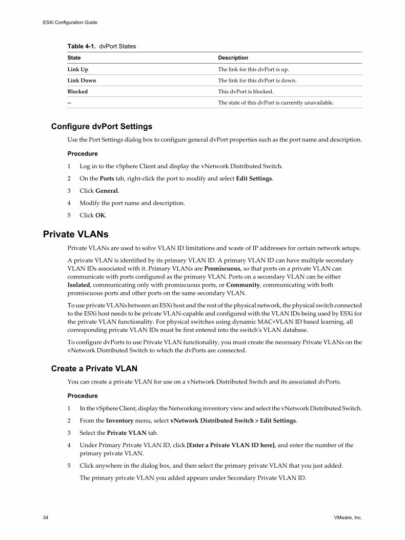
Table 4-1. dvPort States
State Description
Link Up The link for this dvPort is up.
Link Down The link for this dvPort is down.
Blocked This dvPort is blocked.
-- The state of this dvPort is currently unavailable.
Configure dvPort SettingsUse the Port Settings dialog box to configure general dvPort properties such as the port name and description.
Procedure
1 Log in to the vSphere Client and display the vNetwork Distributed Switch.
2 On the Ports tab, right-click the port to modify and select Edit Settings.
3 Click General.
4 Modify the port name and description.
5 Click OK.
Private VLANsPrivate VLANs are used to solve VLAN ID limitations and waste of IP addresses for certain network setups.
A private VLAN is identified by its primary VLAN ID. A primary VLAN ID can have multiple secondaryVLAN IDs associated with it. Primary VLANs are Promiscuous, so that ports on a private VLAN cancommunicate with ports configured as the primary VLAN. Ports on a secondary VLAN can be eitherIsolated, communicating only with promiscuous ports, or Community, communicating with bothpromiscuous ports and other ports on the same secondary VLAN.
To use private VLANs between an ESXi host and the rest of the physical network, the physical switch connectedto the ESXi host needs to be private VLAN-capable and configured with the VLAN IDs being used by ESXi forthe private VLAN functionality. For physical switches using dynamic MAC+VLAN ID based learning, allcorresponding private VLAN IDs must be first entered into the switch's VLAN database.
To configure dvPorts to use Private VLAN functionality, you must create the necessary Private VLANs on thevNetwork Distributed Switch to which the dvPorts are connected.
Create a Private VLANYou can create a private VLAN for use on a vNetwork Distributed Switch and its associated dvPorts.
Procedure
1 In the vSphere Client, display the Networking inventory view and select the vNetwork Distributed Switch.
2 From the Inventory menu, select vNetwork Distributed Switch > Edit Settings.
3 Select the Private VLAN tab.
4 Under Primary Private VLAN ID, click [Enter a Private VLAN ID here], and enter the number of theprimary private VLAN.
5 Click anywhere in the dialog box, and then select the primary private VLAN that you just added.
The primary private VLAN you added appears under Secondary Private VLAN ID.
ESXi Configuration Guide
34 VMware, Inc.

6 For each new secondary private VLAN, click [Enter a Private VLAN ID here] under Secondary PrivateVLAN ID, and enter the number of the secondary private VLAN.
7 Click anywhere in the dialog box, select the secondary private VLAN that you just added, and select eitherIsolated or Community for the port type.
8 Click OK.
Remove a Primary Private VLANRemove unused primary private VLANs from the networking inventory view of the vSphere Client.
Prerequisites
Before removing a private VLAN, be sure that no port groups are configured to use it.
Procedure
1 In the vSphere Client, display the Networking inventory view and select the vNetwork Distributed Switch.
2 From the Inventory menu, select vNetwork Distributed Switch > Edit Settings.
3 Select the Private VLAN tab.
4 Select the primary private VLAN to remove.
5 Click Remove under Primary Private VLAN ID, and click OK.
Removing a primary private VLAN also removes all associated secondary private VLANs.
Remove a Secondary Private VLANRemove unused secondary private VLANs from the networking inventory view of the vSphere Client.
Prerequisites
Before removing a private VLAN, be sure that no port groups are configured to use it.
Procedure
1 In the vSphere Client, display the Networking inventory view and select the vNetwork Distributed Switch.
2 From the Inventory menu, select vNetwork Distributed Switch > Edit Settings.
3 Select the Private VLAN tab.
4 Select a primary private VLAN to display its associated secondary private VLANs.
5 Select the secondary private VLAN to remove.
6 Click Remove under Secondary Private VLAN ID, and click OK.
Chapter 4 Basic Networking with vNetwork Distributed Switches
VMware, Inc. 35

Configuring vNetwork Distributed Switch Network AdaptersThe vNetwork Distributed Switch networking view of the host configuration page displays the configurationof the host’s associated vNetwork Distributed Switches and allows you to configure the vNetwork DistributedSwitch network adapters and uplink ports.
Managing Physical AdaptersFor each host associated with a vNetwork Distributed Switch, you must assign physical network adapters, oruplinks, to the vNetwork Distributed Switch. You can assign one uplink on each host per uplink port on thevNetwork Distributed Switch.
Add an Uplink to a vNetwork Distributed SwitchFor each host associated with a vNetwork Distributed Switch, you must assign at least one physical networkadapter, or uplink, to the vNetwork Distributed Switch.
Procedure
1 Log in to the vSphere Client and select a host from the inventory panel.
The hardware configuration page for the selected host appears.
2 Click the Configuration tab and click Networking.
3 Select the vNetwork Distributed Switch view.
4 Click Manage Physical Adapters.
5 Click Click to Add NIC for the uplink port to add an uplink to.
6 Select the physical adapter to add.
If you select an adapter that is attached to another switch, it will be removed from that switch andreassigned to this vNetwork Distributed Switch.
7 Click OK.
Remove an Uplink from a vNetwork Distributed SwitchYou can remove an uplink, or physical network adapter, from a vNetwork Distributed Switch.
Procedure
1 Log in to the vSphere Client and select the host from the inventory panel.
The hardware configuration page for this server appears.
2 Click the Configuration tab and click Networking.
3 Select the vNetwork Distributed Switch view.
4 Click Manage Physical Adapters.
5 Click Remove to remove the uplink from the vNetwork Distributed Switch.
6 Click OK.
Managing Virtual Network AdaptersVirtual network adapters handle host network services over a vNetwork Distributed Switch.
You can configure VMkernel virtual adapters for an ESXi host through an associated vNetwork DistributedSwitch either by creating new virtual adapters or migrating existing virtual adapters.
ESXi Configuration Guide
36 VMware, Inc.

Create a VMkernel Network Adapter on a vNetwork Distributed SwitchCreate a VMkernel network adapter for use as a vMotion interface or an IP storage port group.
Procedure
1 Log in to the vSphere Client and select the host from the inventory panel.
2 Click the Configuration tab and click Networking.
3 Select the vNetwork Distributed Switch view.
4 Click Manage Virtual Adapters.
5 Click Add.
6 Select New virtual adapter, and click Next.
7 Select VMkernel and click Next.
8 Choose a dvPort or dvPort group connection for the virtual adapter.
Option Description
Select a port group Choose the dvPort group for the virtual adapter to connect to from the drop-down menu.
Select port Choose the dvPort for the virtual adapter to connect to from the drop-downmenu.
9 Select Use this virtual adapter for vMotion to enable this port group to advertise itself to another ESXi
host as the network connection where vMotion traffic is sent.
You can enable this property for only one vMotion and IP storage port group for each ESXi host. If thisproperty is not enabled for any port group, migration with vMotion to this host is not possible.
10 Choose whether to Use this virtual adapter for fault tolerance logging.
11 Choose whether to Use this virtual adapter for management traffic, and click Next.
12 Under IP Settings, specify the IP address and subnet mask.
IPv6 cannot be used with a dependent hardware iSCSI adapter.
13 Click Edit to set the VMkernel default gateway for VMkernel services, such as vMotion, NAS, and iSCSI.
14 On the DNS Configuration tab, the name of the host is entered by default. The DNS server addresses anddomain that were specified during installation are also preselected.
15 On the Routing tab, enter gateway information for the VMkernel. A gateway is needed for connectivityto machines not on the same IP subnet as the VMkernel.
Static IP settings is the default. Do not use routing with software iSCSI Multipathing configurations ordependent hardware iSCSI adapters.
16 Click OK, and then click Next.
17 Click Finish.
Migrate an Existing Virtual Adapter to a vNetwork Distributed SwitchYou can migrate an existing virtual adapter from a vNetwork Standard Switch to a vNetwork DistributedSwitch.
Procedure
1 Log in to the vSphere Client and select the host from the inventory panel.
Chapter 4 Basic Networking with vNetwork Distributed Switches
VMware, Inc. 37
2 Click the Configuration tab and click Networking.
3 Select the vNetwork Distributed Switch view.
4 Click Manage Virtual Adapters.
5 Click Add.
6 Select Migrate existing virtual network adapters and click Next.
7 Select one or more virtual network adapters to migrate.
8 For each selected adapter, choose a port group from the Select a port group drop-down menu.
9 Click Next.
10 Click Finish.
Migrate a Virtual Adapter to a vNetwork Standard SwitchUse the Migrate to Virtual Switch wizard to migrate an existing virtual adapter from a vNetwork DistriubtedSwitch to a vNetwork Standard Switch.
Procedure
1 Log in to the vSphere Client and select the host from the inventory panel.
The hardware configuration page for this server appears.
2 Click the Configuration tab and click Networking.
3 Select the vNetwork Distributed Switch view.
4 Click Manage Virtual Adapters.
5 Select the virtual adapter to migrate, and click Migrate to Virtual Switch.
The Migrate Virtual Adapter wizard appears.
6 Select the vSwitch to migrate the adapter to and click Next.
7 Enter a Network Label and optionally a VLAN ID for the virtual adapter, and click Next.
8 Click Finish to migrate the virtual adapter and complete the wizard.
Edit the VMkernel Configuration on a vNetwork Distributed SwitchYou can edit the properties of an existing VMkernel adapter on a vNetwork Distributed Switch from theassociated host.
Procedure
1 Log in to the vSphere Client and select the host from the inventory panel.
2 Click the Configuration tab and click Networking.
3 Select the vNetwork Distributed Switch view.
4 Click Manage Virtual Adapters.
5 Select the VMkernel adapter to modify and click Edit.
ESXi Configuration Guide
38 VMware, Inc.

6 Choose a dvPort or dvPort group connection for the virtual adapter.
Option Description
Select a port group Choose the dvPort group for the virtual adapter to connect to from the drop-down menu.
Select port Choose the dvPort for the virtual adapter to connect to from the drop-downmenu.
7 Select Use this virtual adapter for vMotion to enable this port group to advertise itself to another ESXi
host as the network connection where vMotion traffic is sent.
You can enable this property for only one vMotion and IP storage port group for each ESXi host. If thisproperty is not enabled for any port group, migration with vMotion to this host is not possible.
8 Choose whether to Use this virtual adapter for fault tolerance logging.
9 Choose whether to Use this virtual adapter for management traffic, and click Next.
10 Under IP Settings, specify the IP address and subnet mask, or select Obtain IP settings automatically.
11 Click Edit to set the VMkernel default gateway for VMkernel services, such as vMotion, NAS, and iSCSI.
12 Click OK.
Remove a Virtual AdapterRemove a virtual network adapter from a vNetwork Distributed Switch in the Manage Virtual Adapters dialogbox.
Procedure
1 Log in to the vSphere Client and select the host from the inventory panel.
2 Click the Configuration tab and click Networking.
3 Select the vNetwork Distributed Switch view.
4 Click Manage Virtual Adapters.
5 Select the virtual adapter to remove and click Remove.
A dialog box appears with the message, Are you sure you want to remove <adapter name>?
6 Click Yes.
Configuring Virtual Machine Networking on a vNetwork DistributedSwitch
Connect virtual machines to a vNetwork Distributed Switch either by configuring an individual virtualmachine NIC or migrating groups of virtual machines from the vNetwork Distributed Switch itself.
Connect virtual machines to vNetwork Distributed Switches by connecting their associated virtual networkadapters to dvPort groups. You can do this either for an individual virtual machine by modifying the virtualmachine’s network adapter configuration, or for a group of virtual machines by migrating virtual machinesfrom an existing virtual network to a vNetwork Distributed Switch.
Chapter 4 Basic Networking with vNetwork Distributed Switches
VMware, Inc. 39

Migrate Virtual Machines to or from a vNetwork Distributed SwitchIn addition to connecting virtual machines to a vNetwork Distributed Switch at the individual virtual machinelevel, you can migrate a group of virtual machines between a vNetwork Distributed Switch network and avNetwork Standard Switch network.
Procedure
1 In the vSphere Client, display the Networking inventory view and select the vNetwork Distributed Switch.
2 From the Inventory menu, select vNetwork Distributed Switch > Migrate Virtual MachineNetworking.
The Migrate Virtual Machine Networking wizard appears.
3 In the Select Source Network drop-down menu, select the virtual network to migrate from.
4 Select the virtual network to migrate to from the Select Destination Network drop-down menu.
5 Click Show Virtual Machines.
Virtual machines associated with the virtual network you are migrating from are displayed in the SelectVirtual Machines field.
6 Select virtual machines to migrate to the destination virtual network, and click OK.
Connect an Individual Virtual Machine to a dvPort GroupConnect an individual virtual machine to a vNetwork Distributed Switch by modifying the virtual machine'sNIC configuration.
Procedure
1 Log in to the vSphere Client and select the virtual machine from the inventory panel.
2 On the Summary tab, click Edit Settings.
3 On the Hardware tab, select the virtual network adapter.
4 Select the dvPort group to migrate to from the Network Label drop-down menu, and click OK.
Network I/O ControlNetwork resource pools determine the priority that different network traffic types are given on a vDS.
When Network I/O Control is enabled, vDS traffic is divided into the following network resource pools: FTtraffic, iSCSI traffic, vMotion traffic, management traffic, NFS traffic, and virtual machine traffic. You cancontrol the priority of the traffic from each of these network resource pools is given by setting the Physicaladapter shares and Host limits for each network resource pool.
ESXi Configuration Guide
40 VMware, Inc.

The Physical adapter shares assigned to a network resource pool determine the share of the total availablebandwidth guaranteed to the traffic associated with that network resource pool. The share of transmitbandwidth available to a network resource pool is determined by the network resource pool's shares and whatother network resource pools are actively transmitting. For example, if you set your FT traffic and iSCSI trafficresource pools to 100 shares, while each of the other resource pools is set to 50 shares, the FT traffic and iSCSItraffic resource pools each receive 25% of the available bandwidth. The remaining resource pools each receive12.5% of the available bandwidth. These reservations apply only when the physical adapter is saturated.
NOTE The iSCSI traffic resource pool shares do not apply to iSCSI traffic on a dependent hardware iSCSIadapter.
The Host limit of a network resource pool is the upper limit of bandwidth that the network resource pool canuse.
Enable Network I/O Control on a vDSEnable network resource management to use network resource pools to prioritize network traffic by type.
Prerequisites
Verify that your datacenter has at least one vNetwork Distributed Switch version 4.1.
Procedure
1 In the vSphere Client, select the Networking inventory view and select the vNetwork Distributed Switch.
2 On the Resource Allocation tab, click Properties.
3 Select Enable network resource management on this vDS, and click OK.
Edit Network Resource Pool SettingsYou can change network resource pool settings such as allocated shares and limits for the resource pool foreach network resource pool.
Procedure
1 In the vSphere Client, select the Networking inventory view and select the vNetwork Distributed Switch.
2 On the Resource Allocation tab, right-click the network resource pool to edit, and select Edit Settings.
3 Select the Physical adapter shares for the network resource pool.
Option Description
Custom Enter a specific number of shares, from 1 to 100, for this network resourcepool.
High Sets the shares for this resource pool to 100.
Normal Sets the shares for this resource pool to 50.
Low Sets the shares for this resource pool to 25.
4 Set the Host limit for the network resource pool in megabits per second or select Unlimited.
5 Click OK.
Chapter 4 Basic Networking with vNetwork Distributed Switches
VMware, Inc. 41

ESXi Configuration Guide
42 VMware, Inc.

Advanced Networking 5The following topics guide you through advanced networking in an ESXi environment, and how to set up andchange advanced networking configuration options.
This chapter includes the following topics:
n “Internet Protocol Version 6,” on page 43
n “VLAN Configuration,” on page 44
n “Networking Policies,” on page 44
n “Change the DNS and Routing Configuration,” on page 58
n “MAC Addresses,” on page 59
n “TCP Segmentation Offload and Jumbo Frames,” on page 60
n “NetQueue and Networking Performance,” on page 63
n “VMDirectPath I/O,” on page 63
Internet Protocol Version 6vSphere supports both Internet Protocol version 4 (IPv4) and Internet Protocol version 6 (IPv6) environments.
The Internet Engineering Task Force has designated IPv6 as the successor to IPv4. The adoption of IPv6, bothas a standalone protocol and in a mixed environment with IPv4, is rapidly increasing. With IPv6, you can usevSphere features in an IPv6 environment.
A major difference between IPv4 and IPv6 is address length. IPv6 uses a 128-bit address rather than the 32-bitaddresses used by IPv4. This helps alleviate the problem of address exhaustion that is present with IPv4 andeliminates the need for network address translation (NAT). Other notable differences include link-localaddresses that appear as the interface is initialized, addresses that are set by router advertisements, and theability to have multiple IPv6 addresses on an interface.
An IPv6-specific configuration in vSphere involves providing IPv6 addresses, either by entering staticaddresses or by using an automatic address configuration scheme for all relevant vSphere networkinginterfaces.
Enable IPv6 Support on an ESXi HostYou can enable or disable IPv6 support on the host. IPv6 is disabled by default.
Procedure
1 Click the arrow next to the Inventory button in the navigation bar and select Hosts and Clusters.
2 Select the host and click the Configuration tab.
VMware, Inc. 43

3 Click the Networking link under Hardware.
4 In the Virtual Switch view, click the Properties link.
5 Select Enable IPv6 support on this host and click OK.
6 Reboot the host.
VLAN ConfigurationVirtual LANs (VLANs) enable a single physical LAN segment to be further segmented so that groups of portsare isolated from one another as if they were on physically different segments.
Configuring ESXi with VLANs is recommended for the following reasons.
n It integrates the host into a pre-existing environment.
n It secures network traffic.
n It reduces network traffic congestion.
n iSCSI traffic requires an isolated network.
You can configure VLANs in ESXi using three methods: External Switch Tagging (EST), Virtual Switch Tagging(VST), and Virtual Guest Tagging (VGT).
With EST, all VLAN tagging of packets is performed on the physical switch. Host network adapters areconnected to access ports on the physical switch. Port groups that are connected to the virtual switch musthave their VLAN ID set to 0.
With VST, all VLAN tagging of packets is performed by the virtual switch before leaving the host. Host networkadapters must be connected to trunk ports on the physical switch. Port groups that are connected to the virtualswitch must have an appropriate VLAN ID specified.
With VGT, all VLAN tagging is performed by the virtual machine. VLAN tags are preserved between thevirtual machine networking stack and external switch when frames are passed to and from virtual switches.Physical switch ports are set to trunk port.
NOTE When using VGT, you must have an 802.1Q VLAN trunking driver installed on the virtual machine.
Networking PoliciesPolicies set at the vSwitch or dvPort group level apply to all of the port groups on that vSwitch or to dvPortsin the dvPort group, except for the configuration options that are overridden at the port group or dvPort level.
You can apply the following networking policies.
n Load balancing and failover
n VLAN (vNetwork Distributed Switch only)
n Security
n Traffic shaping
n Port blocking policies (vNetwork Distributed Switch only)
ESXi Configuration Guide
44 VMware, Inc.

Load Balancing and Failover PolicyLoad balancing and failover policies allow you to determine how network traffic is distributed betweenadapters and how to re-route traffic in the event of adapter failure.
You can edit your load balancing and failover policy by configuring the following parameters:
n Load Balancing policy determines how outgoing traffic is distributed among the network adaptersassigned to a vSwitch.
NOTE Incoming traffic is controlled by the load balancing policy on the physical switch.
n Failover Detection controls the link status and beacon probing. Beaconing is not supported with guestVLAN tagging.
n Network Adapter Order can be active or standby.
Edit the Failover and Load Balancing Policy on a vSwitchFailover and load balancing policies allow you to determine how network traffic is distributed betweenadapters and how to re-route traffic in the event of an adapter failure.
Procedure
1 Log in to the vSphere Client and select the host from the inventory panel.
2 Click the Configuration tab, and click Networking.
3 Select a vSwitch and click Properties.
4 In the vSwitch Properties dialog box, click the Ports tab.
5 To edit the failover and load balancing values for the vSwitch, select the vSwitch item and clickProperties.
6 Click the NIC Teaming tab.
You can override the failover order at the port group level. By default, new adapters are active for allpolicies. New adapters carry traffic for the vSwitch and its port group unless you specify otherwise.
Chapter 5 Advanced Networking
VMware, Inc. 45
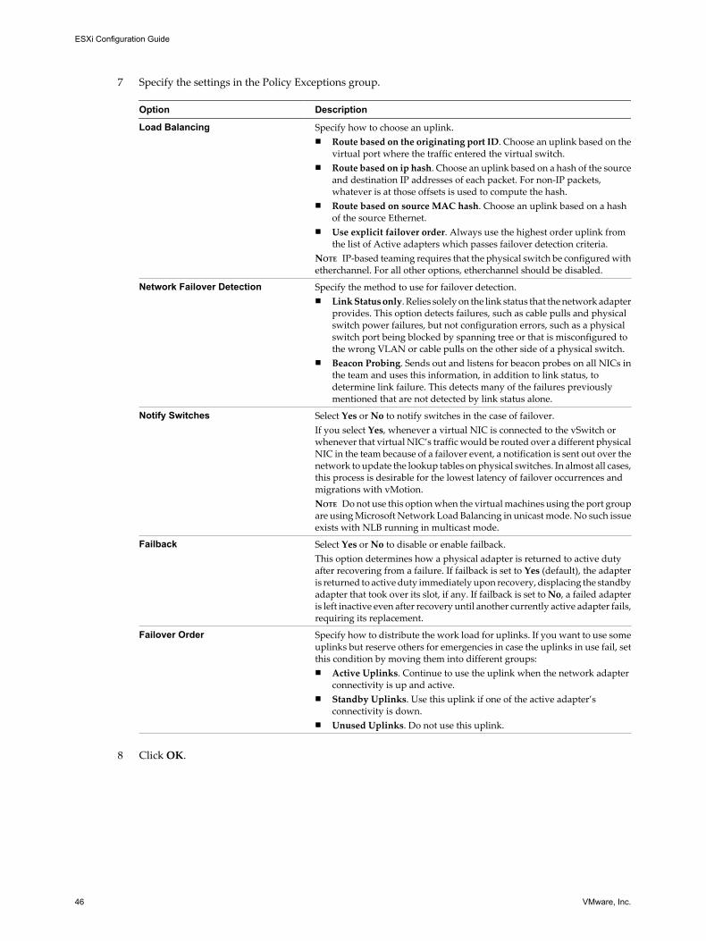
7 Specify the settings in the Policy Exceptions group.
Option Description
Load Balancing Specify how to choose an uplink.n Route based on the originating port ID. Choose an uplink based on the
virtual port where the traffic entered the virtual switch.n Route based on ip hash. Choose an uplink based on a hash of the source
and destination IP addresses of each packet. For non-IP packets,whatever is at those offsets is used to compute the hash.
n Route based on source MAC hash. Choose an uplink based on a hashof the source Ethernet.
n Use explicit failover order. Always use the highest order uplink fromthe list of Active adapters which passes failover detection criteria.
NOTE IP-based teaming requires that the physical switch be configured withetherchannel. For all other options, etherchannel should be disabled.
Network Failover Detection Specify the method to use for failover detection.n Link Status only. Relies solely on the link status that the network adapter
provides. This option detects failures, such as cable pulls and physicalswitch power failures, but not configuration errors, such as a physicalswitch port being blocked by spanning tree or that is misconfigured tothe wrong VLAN or cable pulls on the other side of a physical switch.
n Beacon Probing. Sends out and listens for beacon probes on all NICs inthe team and uses this information, in addition to link status, todetermine link failure. This detects many of the failures previouslymentioned that are not detected by link status alone.
Notify Switches Select Yes or No to notify switches in the case of failover.If you select Yes, whenever a virtual NIC is connected to the vSwitch orwhenever that virtual NIC’s traffic would be routed over a different physicalNIC in the team because of a failover event, a notification is sent out over thenetwork to update the lookup tables on physical switches. In almost all cases,this process is desirable for the lowest latency of failover occurrences andmigrations with vMotion.NOTE Do not use this option when the virtual machines using the port groupare using Microsoft Network Load Balancing in unicast mode. No such issueexists with NLB running in multicast mode.
Failback Select Yes or No to disable or enable failback.This option determines how a physical adapter is returned to active dutyafter recovering from a failure. If failback is set to Yes (default), the adapteris returned to active duty immediately upon recovery, displacing the standbyadapter that took over its slot, if any. If failback is set to No, a failed adapteris left inactive even after recovery until another currently active adapter fails,requiring its replacement.
Failover Order Specify how to distribute the work load for uplinks. If you want to use someuplinks but reserve others for emergencies in case the uplinks in use fail, setthis condition by moving them into different groups:n Active Uplinks. Continue to use the uplink when the network adapter
connectivity is up and active.n Standby Uplinks. Use this uplink if one of the active adapter’s
connectivity is down.n Unused Uplinks. Do not use this uplink.
8 Click OK.
ESXi Configuration Guide
46 VMware, Inc.

Edit the Failover and Load Balancing Policy on a Port GroupFFailover and load balancing policies allow you to determine how network traffic is distributed betweenadapters and how to re-route traffic in the event of an adapter failure.
Procedure
1 Log in to the vSphere Client and select the host from the inventory panel.
2 Click the Configuration tab and click Networking.
3 Select a port group and click Edit.
4 In the Properties dialog box, click the Ports tab.
5 To edit the Failover and Load Balancing values for the port group, select the port group and clickProperties.
6 Click the NIC Teaming tab.
You can override the failover order at the port-group level. By default, new adapters are active for allpolicies. New adapters carry traffic for the vSwitch and its port group unless you specify otherwise.
7 Specify the settings in the Policy Exceptions group.
Option Description
Load Balancing Specify how to choose an uplink.n Route based on the originating port ID. Choose an uplink based on the
virtual port where the traffic entered the virtual switch.n Route based on ip hash. Choose an uplink based on a hash of the source
and destination IP addresses of each packet. For non-IP packets,whatever is at those offsets is used to compute the hash.
n Route based on source MAC hash. Choose an uplink based on a hashof the source Ethernet.
n Use explicit failover order. Always use the highest order uplink fromthe list of Active adapters which passes failover detection criteria.
NOTE IP-based teaming requires that the physical switch be configured withetherchannel. For all other options, etherchannel should be disabled.
Network Failover Detection Specify the method to use for failover detection.n Link Status only. Relies solely on the link status that the network adapter
provides. This option detects failures, such as cable pulls and physicalswitch power failures, but not configuration errors, such as a physicalswitch port being blocked by spanning tree or that is misconfigured tothe wrong VLAN or cable pulls on the other side of a physical switch.
n Beacon Probing. Sends out and listens for beacon probes on all NICs inthe team and uses this information, in addition to link status, todetermine link failure. This detects many of the failures previouslymentioned that are not detected by link status alone.
Notify Switches Select Yes or No to notify switches in the case of failover.If you select Yes, whenever a virtual NIC is connected to the vSwitch orwhenever that virtual NIC’s traffic would be routed over a different physicalNIC in the team because of a failover event, a notification is sent out over thenetwork to update the lookup tables on physical switches. In almost all cases,this process is desirable for the lowest latency of failover occurrences andmigrations with vMotion.NOTE Do not use this option when the virtual machines using the port groupare using Microsoft Network Load Balancing in unicast mode. No such issueexists with NLB running in multicast mode.
Chapter 5 Advanced Networking
VMware, Inc. 47

Option Description
Failback Select Yes or No to disable or enable failback.This option determines how a physical adapter is returned to active dutyafter recovering from a failure. If failback is set to Yes (default), the adapteris returned to active duty immediately upon recovery, displacing the standbyadapter that took over its slot, if any. If failback is set to No, a failed adapteris left inactive even after recovery until another currently active adapter fails,requiring its replacement.
Failover Order Specify how to distribute the work load for uplinks. If you want to use someuplinks but reserve others for emergencies in case the uplinks in use fail, setthis condition by moving them into different groups:n Active Uplinks. Continue to use the uplink when the network adapter
connectivity is up and active.n Standby Uplinks. Use this uplink if one of the active adapter’s
connectivity is down.n Unused Uplinks. Do not use this uplink.
8 Click OK.
Edit the Teaming and Failover Policy on a dvPort GroupTeaming and Failover policies allow you to determine how network traffic is distributed between adaptersand how to re-route traffic in the event of an adapter failure.
Procedure
1 In the vSphere Client, display the Networking inventory view and select the dvPort group.
2 From the Inventory menu, select Network > Edit Settings.
3 Select Policies.
4 In the Teaming and Failover group, specify the following.
Option Description
Load Balancing Specify how to choose an uplink.n Route based on the originating port ID — Choose an uplink based on
the virtual port where the traffic entered the virtual switch.n Route based on ip hash — Choose an uplink based on a hash of the
source and destination IP addresses of each packet. For non-IP packets,whatever is at those offsets is used to compute the hash.
n Route based on source MAC hash — Choose an uplink based on a hashof the source Ethernet.
n Route based on physical NIC load — Choose an uplink based on thecurrent loads of physical NICs.
n Use explicit failover order — Always use the highest order uplink fromthe list of Active adapters which passes failover detection criteria.
NOTE IP-based teaming requires that the physical switch be configured withetherchannel. For all other options, etherchannel should be disabled.
Network Failover Detection Specify the method to use for failover detection.n Link Status only – Relies solely on the link status that the network
adapter provides. This option detects failures, such as cable pulls andphysical switch power failures, but not configuration errors, such as aphysical switch port being blocked by spanning tree or that ismisconfigured to the wrong VLAN or cable pulls on the other side of aphysical switch.
n Beacon Probing – Sends out and listens for beacon probes on all NICsin the team and uses this information, in addition to link status, todetermine link failure. This detects many of the failures previouslymentioned that are not detected by link status alone.
NOTE Do not use beacon probing with IP-hash load balancing.
ESXi Configuration Guide
48 VMware, Inc.

Option Description
Notify Switches Select Yes or No to notify switches in the case of failover.If you select Yes, whenever a virtual NIC is connected to the vSwitch orwhenever that virtual NIC’s traffic would be routed over a different physicalNIC in the team because of a failover event, a notification is sent out over thenetwork to update the lookup tables on physical switches. In almost all cases,this process is desirable for the lowest latency of failover occurrences andmigrations with vMotion.NOTE Do not use this option when the virtual machines using the port groupare using Microsoft Network Load Balancing in unicast mode. No such issueexists with NLB running in multicast mode.
Failback Select Yes or No to disable or enable failback.This option determines how a physical adapter is returned to active dutyafter recovering from a failure. If failback is set to Yes (default), the adapteris returned to active duty immediately upon recovery, displacing the standbyadapter that took over its slot, if any. If failback is set to No, a failed adapteris left inactive even after recovery until another currently active adapter fails,requiring its replacement.
Failover Order Specify how to distribute the work load for uplinks. If you want to use someuplinks but reserve others for emergencies in case the uplinks in use fail, setthis condition by moving them into different groups:n Active Uplinks — Continue to use the uplink when the network adapter
connectivity is up and active.n Standby Uplinks— Use this uplink if one of the active adapter’s
connectivity is down.n Unused Uplinks— Do not use this uplink.NOTE When using IP-hash load balancing, do not configure standby uplinks.
5 Click OK.
Edit dvPort Teaming and Failover PoliciesTeaming and Failover policies allow you to determine how network traffic is distributed between adaptersand how to re-route traffic in the event of an adapter failure.
Prerequisites
To edit the teaming and failover policies on an individual dvPort, the associated dvPort group must be set toallow policy overrides.
Procedure
1 Log in to the vSphere Client and display the vNetwork Distributed Switch.
2 On the Ports tab, right-click the port to modify and select Edit Settings.
The Port Settings dialog box appears.
3 Click Policies to view and modify port networking policies.
Chapter 5 Advanced Networking
VMware, Inc. 49

4 In the Teaming and Failover group, specify the following.
Option Description
Load Balancing Specify how to choose an uplink.n Route based on the originating port ID — Choose an uplink based on
the virtual port where the traffic entered the virtual switch.n Route based on ip hash — Choose an uplink based on a hash of the
source and destination IP addresses of each packet. For non-IP packets,whatever is at those offsets is used to compute the hash.
n Route based on source MAC hash — Choose an uplink based on a hashof the source Ethernet.
n Route based on physical NIC load — Choose an uplink based on thecurrent loads of physical NICs.
n Use explicit failover order — Always use the highest order uplink fromthe list of Active adapters which passes failover detection criteria.
NOTE IP-based teaming requires that the physical switch be configured withetherchannel. For all other options, etherchannel should be disabled.
Network Failover Detection Specify the method to use for failover detection.n Link Status only – Relies solely on the link status that the network
adapter provides. This option detects failures, such as cable pulls andphysical switch power failures, but not configuration errors, such as aphysical switch port being blocked by spanning tree or that ismisconfigured to the wrong VLAN or cable pulls on the other side of aphysical switch.
n Beacon Probing – Sends out and listens for beacon probes on all NICsin the team and uses this information, in addition to link status, todetermine link failure. This detects many of the failures previouslymentioned that are not detected by link status alone.
NOTE Do not use beacon probing with IP-hash load balancing.
Notify Switches Select Yes or No to notify switches in the case of failover.If you select Yes, whenever a virtual NIC is connected to the vSwitch orwhenever that virtual NIC’s traffic would be routed over a different physicalNIC in the team because of a failover event, a notification is sent out over thenetwork to update the lookup tables on physical switches. In almost all cases,this process is desirable for the lowest latency of failover occurrences andmigrations with vMotion.NOTE Do not use this option when the virtual machines using the port groupare using Microsoft Network Load Balancing in unicast mode. No such issueexists with NLB running in multicast mode.
Failback Select Yes or No to disable or enable failback.This option determines how a physical adapter is returned to active dutyafter recovering from a failure. If failback is set to Yes (default), the adapteris returned to active duty immediately upon recovery, displacing the standbyadapter that took over its slot, if any. If failback is set to No, a failed adapteris left inactive even after recovery until another currently active adapter fails,requiring its replacement.
Failover Order Specify how to distribute the work load for uplinks. If you want to use someuplinks but reserve others for emergencies in case the uplinks in use fail, setthis condition by moving them into different groups:n Active Uplinks — Continue to use the uplink when the network adapter
connectivity is up and active.n Standby Uplinks— Use this uplink if one of the active adapter’s
connectivity is down.n Unused Uplinks— Do not use this uplink.NOTE When using IP-hash load balancing, do not configure standby uplinks.
5 Click OK.
ESXi Configuration Guide
50 VMware, Inc.

VLAN PolicyThe VLAN policy allows virtual networks to join physical VLANs.
Edit the VLAN Policy on a dvPort GroupYou can edit the VLAN policy configuration on a dvPort group.
Procedure
1 In the vSphere Client, display the Networking inventory view and select the dvPort group.
2 From the Inventory menu, select Network > Edit Settings.
3 Select VLAN.
4 Select the VLAN Type to use.
Option Description
None Do not use VLAN.
VLAN In the VLAN ID field, enter a number between 1 and 4094.
VLAN Trunking Enter a VLAN trunk range.
Private VLAN Select an available private VLAN to use.
Edit dvPort VLAN PoliciesA VLAN policy set at the dvPort level allows the individual dvPort to override the VLAN policy set at thedvPort group level.
Prerequisites
To edit the VLAN policies on an individual dvPort, the associated dvPort group must be set to allow policyoverrides.
Procedure
1 Log in to the vSphere Client and display the vNetwork Distributed Switch.
2 On the Ports tab, right-click the port to modify and select Edit Settings.
3 Click Policies.
4 Select the VLAN type to use.
Option Action
None Do not use a VLAN.
VLAN For the VLAN ID, enter a number between 1 and 4095.
VLAN Trunking Enter a VLAN trunk range.
Private VLAN Select an available private VLAN to use.
5 Click OK.
Security PolicyNetworking security policies determine how the adapter filters inbound and outbound frames.
Layer 2 is the Data Link Layer. The three elements of the security policy are promiscuous mode, MAC addresschanges, and forged transmits.
Chapter 5 Advanced Networking
VMware, Inc. 51

In nonpromiscuous mode, a guest adapter listens only to traffic forwarded to own MAC address. Inpromiscuous mode, it can listen to all the frames. By default, guest adapters are set to nonpromiscuous mode.
Edit the Layer 2 Security Policy on a vSwitchControl how inbound and outbound frames are handled by editing Layer 2 Security policies.
Procedure
1 Log in to the VMware vSphere Client and select the host from the inventory panel.
2 Click the Configuration tab, and click Networking.
3 Click Properties for the vSwitch to edit.
4 In the Properties dialog box, click the Ports tab.
5 Select the vSwitch item and click Edit.
6 In the Properties dialog box, click the Security tab.
By default, Promiscuous Mode is set to Reject, and MAC Address Changes and Forged Transmits areset to Accept.
The policy applies to all virtual adapters on the vSwitch, unless the port group for the virtual adapterspecifies a policy exception.
7 In the Policy Exceptions pane, select whether to reject or accept the security policy exceptions.
Table 5-1. Policy Exceptions
Mode Reject Accept
Promiscuous Mode Placing a guest adapter inpromiscuous mode has no effect onwhich frames are received by theadapter.
Placing a guest adapter inpromiscuous mode causes it to detectall frames passed on the vSwitch thatare allowed under the VLAN policyfor the port group that the adapter isconnected to.
MAC Address Changes If the guest OS changes the MACaddress of the adapter to anythingother than what is in the .vmxconfiguration file, all inboundframes are dropped.If the guest OS changes the MACaddress back to match the MACaddress in the .vmx configurationfile, inbound frames are sent again.
If the MAC address from the guest OSchanges, frames to the new MACaddress are received.
Forged Transmits Outbound frames with a sourceMAC address that is different fromthe one set on the adapter aredropped.
No filtering is performed, and alloutbound frames are passed.
8 Click OK.
Edit the Layer 2 Security Policy Exception on a Port GroupControl how inbound and outbound frames are handled by editing Layer 2 Security policies.
Procedure
1 Log in to the VMware vSphere Client and select the host from the inventory panel.
2 Click the Configuration tab, and click Networking.
3 Click Properties for the port group to edit.
ESXi Configuration Guide
52 VMware, Inc.

4 In the Properties dialog box, click the Ports tab.
5 Select the port group item and click Edit.
6 In the Properties dialog box for the port group, click the Security tab.
By default, Promiscuous Mode is set to Reject. MAC Address Changes and Forged Transmitsare set toAccept.
The policy exception overrides any policy set at the vSwitch level.
7 In the Policy Exceptions pane, select whether to reject or accept the security policy exceptions.
Table 5-2. Policy Exceptions
Mode Reject Accept
Promiscuous Mode Placing a guest adapter inpromiscuous mode has no effect onwhich frames are received by theadapter.
Placing a guest adapter inpromiscuous mode causes it to detectall frames passed on the vSwitch thatare allowed under the VLAN policyfor the port group that the adapter isconnected to.
MAC Address Changes If the guest OS changes the MACaddress of the adapter to anythingother than what is in the .vmxconfiguration file, all inboundframes are dropped.If the guest OS changes the MACaddress back to match the MACaddress in the .vmx configurationfile, inbound frames are sent again.
If the MAC address from the guest OSchanges, frames to the new MACaddress are received.
Forged Transmits Outbound frames with a sourceMAC address that is different fromthe one set on the adapter aredropped.
No filtering is performed, and alloutbound frames are passed.
8 Click OK.
Edit the Security Policy on a dvPort GroupControl how inbound and outbound frames for a dvPort group are handled by editing the Security policies.
Procedure
1 In the vSphere Client, display the Networking inventory view and select the dvPort group.
2 From the Inventory menu, select Network > Edit Settings.
3 In the Properties dialog box for the port group, click the Security tab.
By default, Promiscuous Mode is set to Reject. MAC Address Changes and Forged Transmitsare set toAccept.
The policy exception overrides any policy set at the vSwitch level.
Chapter 5 Advanced Networking
VMware, Inc. 53

4 In the Policy Exceptions pane, select whether to reject or accept the security policy exceptions.
Table 5-3. Policy Exceptions
Mode Reject Accept
Promiscuous Mode Placing a guest adapter inpromiscuous mode has no effect onwhich frames are received by theadapter.
Placing a guest adapter inpromiscuous mode causes it to detectall frames passed on the vSwitch thatare allowed under the VLAN policyfor the port group that the adapter isconnected to.
MAC Address Changes If the guest OS changes the MACaddress of the adapter to anythingother than what is in the .vmxconfiguration file, all inboundframes are dropped.If the guest OS changes the MACaddress back to match the MACaddress in the .vmx configurationfile, inbound frames are sent again.
If the MAC address from the guest OSchanges, frames to the new MACaddress are received.
Forged Transmits Outbound frames with a sourceMAC address that is different fromthe one set on the adapter aredropped.
No filtering is performed, and alloutbound frames are passed.
5 Click OK.
Edit dvPort Security PoliciesControl how inbound and outbound frames for a dvPort are handled by editing the Security policies.
Prerequisites
To edit the Security policies on an individual dvPort, the associated dvPort group must be set to allow policyoverrides.
Procedure
1 Log in to the vSphere Client and display the vNetwork Distributed Switch.
2 On the Ports tab, right-click the port to modify and select Edit Settings.
3 Click Policies.
By default, Promiscuous Mode is set to Reject, and MAC Address Changes and Forged Transmitsareset to Accept.
ESXi Configuration Guide
54 VMware, Inc.

4 In the Security group, select whether to reject or accept the security policy exceptions.
Table 5-4. Policy Exceptions
Mode Reject Accept
Promiscuous Mode Placing a guest adapter inpromiscuous mode has no effect onwhich frames are received by theadapter.
Placing a guest adapter inpromiscuous mode causes it to detectall frames passed on the vSwitch thatare allowed under the VLAN policyfor the port group that the adapter isconnected to.
MAC Address Changes If the guest OS changes the MACaddress of the adapter to anythingother than what is in the .vmxconfiguration file, all inboundframes are dropped.If the guest OS changes the MACaddress back to match the MACaddress in the .vmx configurationfile, inbound frames are sent again.
If the MAC address from the guest OSchanges, frames to the new MACaddress are received.
Forged Transmits Outbound frames with a sourceMAC address that is different fromthe one set on the adapter aredropped.
No filtering is performed, and alloutbound frames are passed.
5 Click OK.
Traffic Shaping PolicyA traffic shaping policy is defined by three characteristics: average bandwidth, peak bandwidth, and burstsize. You can establish a traffic shaping policy for each port group and each dvPort or dvPort group.
ESXi shapes outbound network traffic on vSwitches and both inbound and outbound traffic on a vNetworkDistributed Switch. Traffic shaping restricts the network bandwidth available on a port, but can also beconfigured to allow bursts of traffic to flow through at higher speeds.
Average Bandwidth Establishes the number of bits per second to allow across a port, averaged overtime: the allowed average load.
Peak Bandwidth The maximum number of bits per second to allow across a port when it issending or receiving a burst of traffic. This limits the bandwidth used by a portwhenever it is using its burst bonus.
Burst Size The maximum number of bytes to allow in a burst. If this parameter is set, aport might gain a burst bonus if it does not use all its allocated bandwidth.Whenever the port needs more bandwidth than specified by AverageBandwidth, it might be allowed to temporarily transmit data at a higher speedif a burst bonus is available. This parameter limits the number of bytes thathave accumulated in the burst bonus and thus transfers at a higher speed.
Edit the Traffic Shaping Policy on a vSwitchUse traffic shaping policies to control the bandwidth and burst size on a vSwitch.
Procedure
1 Log in to the vSphere Client and select the host from the inventory panel.
2 Click the Configuration tab, and click Networking.
3 Click Properties for the vSwitch to edit.
Chapter 5 Advanced Networking
VMware, Inc. 55

4 In the Properties dialog box, click the Ports tab.
5 Select the vSwitch item and click Edit.
6 In the Properties dialog box, click the Traffic Shaping tab.
When traffic shaping is disabled, the options are dimmed. You can selectively override all traffic-shapingfeatures at the port group level if traffic shaping is enabled.
This policy is applied to each individual virtual adapter attached to the port group, not to the vSwitch asa whole.
NOTE Peak bandwidth cannot be less than the specified average bandwidth.
Option Description
Status If you enable the policy exception in the Status field, you are setting limitson the amount of networking bandwidth allocated for each virtual adapterassociated with this particular port group. If you disable the policy, serviceshave a free and clear connection to the physical network.
Average Bandwidth A value measured over a particular period of time.
Peak Bandwidth Limits the maximum bandwidth during a burst. It can never be smaller thanthe average bandwidth.
Burst Size Specifies how large a burst can be in kilobytes (KB).
Edit the Traffic Shaping Policy on a Port GroupUse traffic shaping policies to control the bandwidth and burst size on a port group.
Procedure
1 Log in to the vSphere Client and select the host from the inventory panel.
2 Click the Configuration tab, and click Networking.
3 Click Properties for the port group to edit.
4 In the Properties dialog box, click the Ports tab.
5 Select the port group item and click Edit.
6 In the Properties dialog box for the port group, click the Traffic Shaping tab.
When traffic shaping is disabled, the options are dimmed.
Option Description
Status If you enable the policy exception in the Status field, you are setting limitson the amount of networking bandwidth allocated for each virtual adapterassociated with this particular port group. If you disable the policy, serviceshave a free and clear connection to the physical network.
Average Bandwidth A value measured over a particular period of time.
Peak Bandwidth Limits the maximum bandwidth during a burst. It can never be smaller thanthe average bandwidth.
Burst Size Specifies how large a burst can be in kilobytes (KB).
ESXi Configuration Guide
56 VMware, Inc.
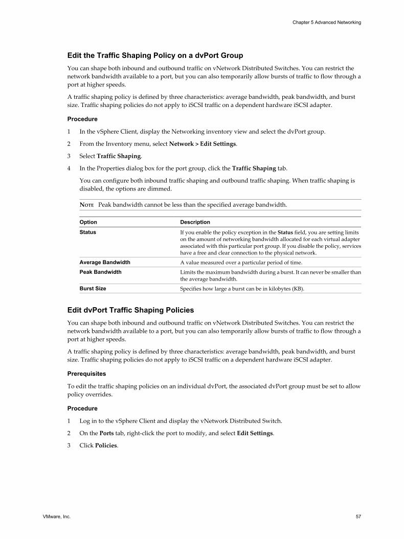
Edit the Traffic Shaping Policy on a dvPort GroupYou can shape both inbound and outbound traffic on vNetwork Distributed Switches. You can restrict thenetwork bandwidth available to a port, but you can also temporarily allow bursts of traffic to flow through aport at higher speeds.
A traffic shaping policy is defined by three characteristics: average bandwidth, peak bandwidth, and burstsize. Traffic shaping policies do not apply to iSCSI traffic on a dependent hardware iSCSI adapter.
Procedure
1 In the vSphere Client, display the Networking inventory view and select the dvPort group.
2 From the Inventory menu, select Network > Edit Settings.
3 Select Traffic Shaping.
4 In the Properties dialog box for the port group, click the Traffic Shaping tab.
You can configure both inbound traffic shaping and outbound traffic shaping. When traffic shaping isdisabled, the options are dimmed.
NOTE Peak bandwidth cannot be less than the specified average bandwidth.
Option Description
Status If you enable the policy exception in the Status field, you are setting limitson the amount of networking bandwidth allocated for each virtual adapterassociated with this particular port group. If you disable the policy, serviceshave a free and clear connection to the physical network.
Average Bandwidth A value measured over a particular period of time.
Peak Bandwidth Limits the maximum bandwidth during a burst. It can never be smaller thanthe average bandwidth.
Burst Size Specifies how large a burst can be in kilobytes (KB).
Edit dvPort Traffic Shaping PoliciesYou can shape both inbound and outbound traffic on vNetwork Distributed Switches. You can restrict thenetwork bandwidth available to a port, but you can also temporarily allow bursts of traffic to flow through aport at higher speeds.
A traffic shaping policy is defined by three characteristics: average bandwidth, peak bandwidth, and burstsize. Traffic shaping policies do not apply to iSCSI traffic on a dependent hardware iSCSI adapter.
Prerequisites
To edit the traffic shaping policies on an individual dvPort, the associated dvPort group must be set to allowpolicy overrides.
Procedure
1 Log in to the vSphere Client and display the vNetwork Distributed Switch.
2 On the Ports tab, right-click the port to modify, and select Edit Settings.
3 Click Policies.
Chapter 5 Advanced Networking
VMware, Inc. 57

4 In the Traffic Shaping group, you can configure both inbound traffic shaping and outbound traffic shaping.
When traffic shaping is disabled, the options are dimmed.
Option Description
Status If you enable the policy exception in the Status field, you are setting limitson the amount of networking bandwidth allocated for each virtual adapterassociated with this particular port group. If you disable the policy, serviceshave a free and clear connection to the physical network.
Average Bandwidth A value measured over a particular period of time.
Peak Bandwidth Limits the maximum bandwidth during a burst. It can never be smaller thanthe average bandwidth.
Burst Size Specifies how large a burst can be in kilobytes (KB).
5 Click OK.
Port Blocking PoliciesSet blocking policies for dvPorts from the miscellaneous policies dialog box.
Edit the Port Blocking Policy on a dvPort GroupSet the port blocking policy for a dvPort group under miscellaneous policies.
Procedure
1 In the vSphere Client, display the Networking inventory view and select the dvPort group.
2 From the Inventory menu, select Network > Edit Settings.
3 Select Miscellaneous.
4 Choose whether to Block all ports on this dvPort group.
Edit dvPort Port Blocking PolicyThe Miscellaneous policies dialog allows you to configure port blocking policies for a dvPort.
Procedure
1 Log in to the vSphere Client and display the vNetwork Distributed Switch.
2 On the Ports tab, right-click the port to modify and select Edit Settings.
3 Click Policies.
4 In the Miscellaneous group, select whether to Block all ports.
5 Click OK.
Change the DNS and Routing ConfigurationYou can change the DNS server and default gateway information provided during installation from the hostconfiguration page in the vSphere Client.
Procedure
1 Log in to the vSphere Client and select the host from the inventory panel.
2 Click the Configuration tab, and click DNS and Routing.
3 On the right side of the window, click Properties.
4 In the DNS Configuration tab, enter a name and domain.
ESXi Configuration Guide
58 VMware, Inc.

5 Choose whether to obtain the DNS server address automatically or use a DNS server address.
6 Specify the domains in which to look for hosts.
7 On the Routing tab, change the default gateway information as needed.
8 Click OK.
MAC AddressesMAC addresses are generated for virtual network adapters that the the VMkernel and virtual machines use.
In most cases, the generated MAC addresses are appropriate. However, you might need to set a MAC addressfor a virtual network adapter, as in the following cases:
n Virtual network adapters on different physical hosts share the same subnet and are assigned the sameMAC address, causing a conflict.
n To ensure that a virtual network adapter always has the same MAC address.
To circumvent the limit of 256 virtual network adapters per physical machine and possible MAC addressconflicts between virtual machines, system administrators can manually assign MAC addresses. VMware usesthe Organizationally Unique Identifier (OUI) 00:50:56 for manually generated addresses.
The MAC address range is 00:50:56:00:00:00-00:50:56:3F:FF:FF.
You can set the addresses by adding the following line to a virtual machine‘s configuration file:
ethernet<number>.address = 00:50:56:XX:YY:ZZ
where <number> refers to the number of the Ethernet adapter, XX is a valid hexadecimal number between 00and 3F, and YY and ZZ are valid hexadecimal numbers between 00 and FF. The value for XX must not be greaterthan 3F to avoid conflict with MAC addresses that are generated by the VMware Workstation and VMwareServer products. The maximum value for a manually generated MAC address is:
ethernet<number>.address = 00:50:56:3F:FF:FF
You must also set the option in a virtual machine’s configuration file:
ethernet<number>.addressType="static"
Because VMware ESXi virtual machines do not support arbitrary MAC addresses, you must use the aboveformat. As long as you choose a unique value for XX:YY:ZZ among your hard-coded addresses, conflictsbetween the automatically assigned MAC addresses and the manually assigned ones should never occur.
MAC Address GenerationEach virtual network adapter in a virtual machine is assigned its own unique MAC address. Each networkadapter manufacturer is assigned a unique three-byte prefix called an Organizationally Unique Identifier(OUI), which it can use to generate unique MAC addresses.
VMware has the following OUIs:
n Generated MAC addresses
n Manually set MAC addresses
n For legacy virtual machines, but no longer used with ESXi
The first three bytes of the MAC address that is generated for each virtual network adapter consists of the OUI.The MAC address-generation algorithm produces the other three bytes. The algorithm guarantees uniqueMAC addresses within a machine and attempts to provide unique MAC addresses across machines.
Chapter 5 Advanced Networking
VMware, Inc. 59

The network adapters for each virtual machine on the same subnet should have unique MAC addresses.Otherwise, they can behave unpredictably. The algorithm puts a limit on the number of running and suspendedvirtual machines at any one time on any given host. It also does not handle all cases when virtual machines ondistinct physical machines share a subnet.
The VMware Universally Unique Identifier (UUID) generates MAC addresses that are checked for conflicts.The generated MAC addresses are created by using three parts: the VMware OUI, the SMBIOS UUID for thephysical ESXi machine, and a hash based on the name of the entity that the MAC address is being generatedfor.
After the MAC address has been generated, it does not change unless the virtual machine is moved to a differentlocation, for example, to a different path on the same server. The MAC address in the configuration file of thevirtual machine is saved. All MAC addresses that have been assigned to network adapters of running andsuspended virtual machines on a given physical machine are tracked.
The MAC address of a powered off virtual machine is not checked against those of running or suspendedvirtual machines. It is possible that when a virtual machine is powered on again, it can acquire a different MACaddress. This acquisition is caused by a conflict with a virtual machine that was powered on when this virtualmachine was powered off.
Set Up a MAC AddressYou can assign stati MAC addresses to a powered-down virtual machine's virtual NICs.
Procedure
1 Log in to the vSphere Client and select the virtual machine from the inventory panel.
2 Click the Summary tab and click Edit Settings.
3 Select the network adapter from the Hardware list.
4 In the MAC Address group, select Manual.
5 Enter the static MAC address, and click OK.
TCP Segmentation Offload and Jumbo FramesYou must enable jumbo frames at the host level by using the command-line interface to configure the MTUsize for each vSwitch. TCP Segmentation Offload (TSO) is enabled on the VMkernel interface by default, butmust be enabled at the virtual machine level.
Enabling TSOTo enable TSO at the virtual machine level, you must replace the existing vmxnet or flexible virtual networkadapters with enhanced vmxnet virtual network adapters. This replacement might result in a change in theMAC address of the virtual network adapter.
TSO support through the enhanced vmxnet network adapter is available for virtual machines that run thefollowing guest operating systems:
n Microsoft Windows 2003 Enterprise Edition with Service Pack 2 (32 bit and 64 bit)
n Red Hat Enterprise Linux 4 (64 bit)
n Red Hat Enterprise Linux 5 (32 bit and 64 bit)
n SUSE Linux Enterprise Server 10 (32 bit and 64 bit)
ESXi Configuration Guide
60 VMware, Inc.
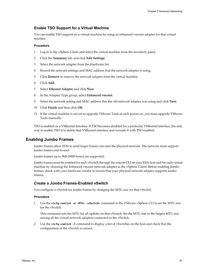
Enable TSO Support for a Virtual MachineYou can enable TSO support on a virtual machine by using an enhanced vmxnet adapter for that virtualmachine.
Procedure
1 Log in to the vSphere Client and select the virtual machine from the inventory panel.
2 Click the Summary tab, and click Edit Settings.
3 Select the network adapter from the Hardware list.
4 Record the network settings and MAC address that the network adapter is using.
5 Click Remove to remove the network adapter from the virtual machine.
6 Click Add.
7 Select Ethernet Adapter and click Next.
8 In the Adapter Type group, select Enhanced vmxnet.
9 Select the network setting and MAC address that the old network adapter was using and click Next.
10 Click Finish and then click OK.
11 If the virtual machine is not set to upgrade VMware Tools at each power on, you must upgrade VMwareTools manually.
TSO is enabled on a VMkernel interface. If TSO becomes disabled for a particular VMkernel interface, the onlyway to enable TSO is to delete that VMkernel interface and recreate it with TSO enabled.
Enabling Jumbo FramesJumbo frames allow ESXi to send larger frames out onto the physical network. The network must supportjumbo frames end-to-end.
Jumbo frames up to 9kB (9000 bytes) are supported.
Jumbo frames must be enabled for each vSwitch through the remote CLI on your ESXi host and for each virtualmachine by choosing the Enhanced vmxnet network adapter in the vSphere Client. Before enabling Jumboframes, check with your hardware vendor to ensure that your physical network adapter supports jumboframes.
Create a Jumbo Frames-Enabled vSwitchYou configure a vSwitch for jumbo frames by changing the MTU size for that vSwitch.
Procedure
1 Use the vicfg-vswitch -m <MTU> <vSwitch> command in the VMware vSphere CLI to set the MTU sizefor the vSwitch.
This command sets the MTU for all uplinks on that vSwitch. Set the MTU size to the largest MTU sizeamong all the virtual network adapters connected to the vSwitch.
2 Use the vicfg-vswitch -l command to display a list of vSwitches on the host and check that theconfiguration of the vSwitch is correct.
Chapter 5 Advanced Networking
VMware, Inc. 61

Enable Jumbo Frames on a vNetwork Distributed SwitchYou enable a vNetwork Distributed Switch for jumbo frames by changing the MTU size for that vNetworkDistributed Switch.
Procedure
1 In the vSphere Client, display the Networking inventory view and select the vNetwork Distributed Switch.
2 From the Inventory menu, select vNetwork Distributed Switch > Edit Settings.
3 On the Properties tab, select Advanced.
4 Set the Maximum MTU to the largest MTU size among all the virtual network adapters connected to thevNetwork Distributed Switch, and click OK.
Enable Jumbo Frame Support on a Virtual MachineEnabling jumbo frame support on a virtual machine requires an enhanced vmxnet adapter for that virtualmachine.
Procedure
1 Log in to the vSphere Client and select the virtual machine from the inventory panel.
2 Click the Summarytab, and click Edit Settings.
3 Select the network adapter from the Hardware list.
4 Record the network settings and MAC address that the network adapter is using.
5 Click Remove to remove the network adapter from the virtual machine.
6 Click Add.
7 Select Ethernet Adapter and click Next.
8 In the Adapter Type group, select Enhanced vmxnet.
9 Select the network that the old network adapter was using and click Next.
10 Click Finish.
11 Select the new network adapter from the Hardware list.
12 Under MAC Address, select Manual, and enter the MAC address that the old network adapter was using.
13 Click OK.
14 Check that the Enhanced vmxnet adapter is connected to a vSwitch with jumbo frames enabled.
15 Inside the guest operating system, configure the network adapter to allow jumbo frames.
See your guest operating system’s documentation for details.
16 Configure all physical switches and any physical or virtual machines to which this virtual machineconnects to support jumbo frames.
Create a Jumbo Frames-Enabled VMkernel InterfaceYou can create a VMkernel network interface enabled with jumbo frames.
Procedure
1 Log in to your ESXi host’s console.
ESXi Configuration Guide
62 VMware, Inc.
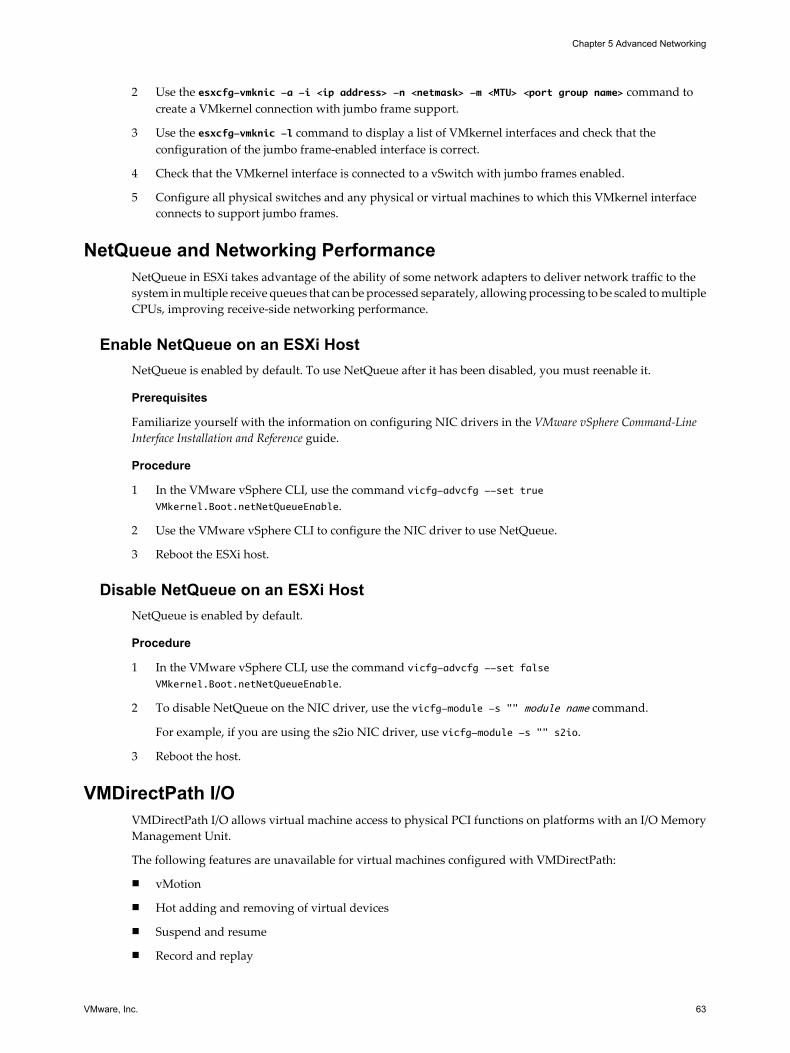
2 Use the esxcfg-vmknic -a -i <ip address> -n <netmask> -m <MTU> <port group name> command tocreate a VMkernel connection with jumbo frame support.
3 Use the esxcfg-vmknic -l command to display a list of VMkernel interfaces and check that theconfiguration of the jumbo frame-enabled interface is correct.
4 Check that the VMkernel interface is connected to a vSwitch with jumbo frames enabled.
5 Configure all physical switches and any physical or virtual machines to which this VMkernel interfaceconnects to support jumbo frames.
NetQueue and Networking PerformanceNetQueue in ESXi takes advantage of the ability of some network adapters to deliver network traffic to thesystem in multiple receive queues that can be processed separately, allowing processing to be scaled to multipleCPUs, improving receive-side networking performance.
Enable NetQueue on an ESXi HostNetQueue is enabled by default. To use NetQueue after it has been disabled, you must reenable it.
Prerequisites
Familiarize yourself with the information on configuring NIC drivers in the VMware vSphere Command-LineInterface Installation and Reference guide.
Procedure
1 In the VMware vSphere CLI, use the command vicfg-advcfg --set trueVMkernel.Boot.netNetQueueEnable.
2 Use the VMware vSphere CLI to configure the NIC driver to use NetQueue.
3 Reboot the ESXi host.
Disable NetQueue on an ESXi HostNetQueue is enabled by default.
Procedure
1 In the VMware vSphere CLI, use the command vicfg-advcfg --set falseVMkernel.Boot.netNetQueueEnable.
2 To disable NetQueue on the NIC driver, use the vicfg-module -s "" module name command.
For example, if you are using the s2io NIC driver, use vicfg-module -s "" s2io.
3 Reboot the host.
VMDirectPath I/OVMDirectPath I/O allows virtual machine access to physical PCI functions on platforms with an I/O MemoryManagement Unit.
The following features are unavailable for virtual machines configured with VMDirectPath:
n vMotion
n Hot adding and removing of virtual devices
n Suspend and resume
n Record and replay
Chapter 5 Advanced Networking
VMware, Inc. 63

n Fault tolerance
n High availability
n DRS (limited availability. The virtual machine can be part of a cluster, but cannot migrate across hosts)
Configure Passthrough Devices on a HostYou can configure passthrough networking devices on a host.
Procedure
1 Select a host from the inventory panel of the vSphere Client.
2 On the Configuration tab, click Advanced Settings.
The Passthrough Configuration page appears, listing all available passthrough devices. A green iconindicates that a device is enabled and active. An orange icon indicates that the state of the device haschanged and the host must be rebooted before the device can be used.
3 Click Edit.
4 Select the devices to be used for passthrough and click OK.
Configure a PCI Device on a Virtual MachineYou can configure a passthrough PCI device on a virtual machine.
Procedure
1 Select a virtual machine from the inventory panel of the vSphere Client.
2 From the Inventory menu, select Virtual Machine > Edit Settings.
3 On the Hardware tab, click Add.
4 Select PCI Device and click Next.
5 Select the passthrough device to use, and click Next.
6 Click Finish.
Adding a VMDirectPath device to a virtual machine sets memory reservation to the memory size of the virtualmachine.
ESXi Configuration Guide
64 VMware, Inc.

Networking Best Practices, Scenarios,and Troubleshooting 6
The following best practices, configuration scenarios, and troubleshooting guidelines provide suggestions forcommon networking configurations and pitfalls.
This chapter includes the following topics:
n “Networking Best Practices,” on page 65
n “Mounting NFS Volumes,” on page 66
n “Networking Configuration for Software iSCSI and Dependent Hardware iSCSI,” on page 66
n “Troubleshooting,” on page 69
Networking Best PracticesConsider these best practices for configuring your network.
n Separate network services from one another to achieve greater security or better performance.
To have a particular set of virtual machines function at the highest performance levels, put them on aseparate physical NIC. This separation allows for a portion of the total networking workload to be moreevenly shared across multiple CPUs. The isolated virtual machines can then better serve traffic from aWeb client, for instance.
n Keep the vMotion connection on a separate network devoted to vMotion. When migration with vMotionoccurs, the contents of the guest operating system’s memory is transmitted over the network. You can dothis either by using VLANs to segment a single physical network or separate physical networks (the latteris preferable).
n When using passthrough devices with a Linux kernel version 2.6.20 or earlier, avoid MSI and MSI-X modesbecause these modes have significant performance impact.
n To physically separate network services and to dedicate a particular set of NICs to a specific networkservice, create a vSwitch for each service. If this is not possible, separate them on a single vSwitch byattaching them to port groups with different VLAN IDs. In either case, confirm with your networkadministrator that the networks or VLANs you choose are isolated in the rest of your environment andthat no routers connect them.
n You can add and remove NICs from the vSwitch without affecting the virtual machines or the networkservice that is running behind that vSwitch. If you remove all the running hardware, the virtual machinescan still communicate among themselves. Moreover, if you leave one NIC intact, all the virtual machinescan still connect with the physical network.
n To protect your most sensitive virtual machines, deploy firewalls in virtual machines that route betweenvirtual networks with uplinks to physical networks and pure virtual networks with no uplinks.
VMware, Inc. 65

Mounting NFS VolumesIn ESXi, the model of how ESXi accesses NFS storage of ISO images that are used as virtual CD-ROMs forvirtual machines is different from the model used in ESX Server 2.x.
ESXi has support for VMkernel-based NFS mounts. The new model is to mount your NFS volume with theISO images through the VMkernel NFS functionality. All NFS volumes mounted in this way appear asdatastores in the vSphere Client.
Networking Configuration for Software iSCSI and Dependent HardwareiSCSI
If you use the software iSCSI adapter or dependent hardware iSCSI adapters, you must set up the networkingfor iSCSI before you can enable and configure your iSCSI adapters. Networking configuration for iSCSIinvolves opening a VMkernel iSCSI port for the traffic between the iSCSI adapter and the physical NIC.
Depending on the number of physical NICs you use for iSCSI traffic, the networking setup can be different.
n If you have a single physical NIC, create one iSCSI port on a vSwitch connected to the NIC. VMwarerecommends that you designate a separate network adapter for iSCSI. Do not use iSCSI on 100Mbps orslower adapters.
n If you have two or more physical NICs for iSCSI, create a separate iSCSI port for each physical NIC anduse the NICs for iSCSI multipathing. See Figure 6-1.
Figure 6-1. Networking with iSCSI
physical NICs
vmnic1 vmnic2 vmnic1 vmnic2
physical NICswith iSCSI
offloadcapabilities
Host1
Host1
Host2
Host2
iSCSIports
software iSCSI adapter dependent hardware iSCSI adapters
vSwitch
vmk1 vmk2 vmk1
vmhba33vmhba# vmhba34
vmk2
vSwitch
virtual
physical
Two physical NICs connected tothe software iSCSI adapter
Two physical NICs with iSCSIoffload capabilities
IP network
iSCSI storage iSCSI storage
NOTE When you use a dependent hardware iSCSI adapter, performance reporting for a NIC associatedwith the adapter might show little or no activity, even when iSCSI traffic is heavy. This behavior occursbecause the iSCSI traffic bypasses the regular networking stack.
ESXi Configuration Guide
66 VMware, Inc.

Create iSCSI Port for a Single NICUse this task to connect the VMkernel, which runs services for iSCSI storage, to a physical NIC. If you havejust one physical network adapter to be used for iSCSI traffic, this is the only procedure you must perform toset up your iSCSI networking.
Procedure
1 Log in to the vSphere Client and select the host from the inventory panel.
2 Click the Configuration tab and click Networking.
3 In the Virtual Switch view, click Add Networking.
4 Select VMkernel and click Next.
5 Select Create a virtual switch to create a new vSwitch.
6 Select a NIC you want to use for iSCSI traffic.
IMPORTANT If you are creating a port for the dependent hardware iSCSI adapter, make sure to select theNIC that corresponds to the iSCSI component. See “Determine Association Between Dependent HardwareiSCSI and Physical Network Adapters,” on page 92.
7 Click Next.
8 Enter a network label.
Network label is a friendly name that identifies the VMkernel port that you are creating, for example,iSCSI.
9 Click Next.
10 Specify the IP settings and click Next.
11 Review the information and click Finish.
Using Multiple NICs for Software and Dependent Hardware iSCSIIf your host has more than one physical NIC for iSCSI, for each physical NIC, create a separate iSCSI port using1:1 mapping.
To achieve the 1:1 mapping, designate a separate vSwitch for each network adapter and iSCSI port pair. See Figure 6-2.
Figure 6-2. iSCSI Ports and NICs on Separate vSwitches
Chapter 6 Networking Best Practices, Scenarios, and Troubleshooting
VMware, Inc. 67

An alternative is to add all NIC and iSCSI port pairs to a single vSwitch. See Figure 6-3. You must override thedefault setup and make sure that each port maps to only one corresponding active NIC.
Figure 6-3. iSCSI Ports and NICs on a Single vSwitch
For information about adding the NIC and VMkernel port pairs to a vSwitch, see “Create Additional iSCSIPorts for Multiple NICs,” on page 68.
After you map iSCSI ports to network adapters, use the esxcli command to bind the ports to the iSCSI adapters.With dependent hardware iSCSI adapters, perform port binding, whether you use one NIC or multiple NICs.For information, see “Bind iSCSI Ports to iSCSI Adapters,” on page 92.
Create Additional iSCSI Ports for Multiple NICsUse this task if you have two or more NICs you can designate for iSCSI and you want to connect all of youriSCSI NICs to a single vSwitch. In this task, you associate VMkernel iSCSI ports with the network adaptersusing 1:1 mapping.
You now need to connect additional NICs to the existing vSwitch and map them to corresponding iSCSI ports.
NOTE If you use a vNetwork Distributed Switch with multiple dvUplinks, for port binding, create a separatedvPort group per each physical NIC. Then set the team policy so that each dvPort group has only one activedvUplink.
For detailed information on vNetwork Distributed Switches, see the Networking section.
Prerequisites
You must create a vSwitch that maps an iSCSI port to a physical NIC designated for iSCSI traffic.
Procedure
1 Log in to the vSphere Client and select the host from the inventory panel.
2 Click the Configuration tab and click Networking.
3 Select the vSwitch that you use for iSCSI and click Properties.
4 Connect additional network adapters to the vSwitch.
a In the vSwitch Properties dialog box, click the Network Adapters tab and click Add.
b Select one or more NICs from the list and click Next.
With dependent hardware iSCSI adapters, make sure to select only those NICs that have acorresponding iSCSI component.
c Review the information on the Adapter Summary page, and click Finish.
The list of network adapters reappears, showing the network adapters that the vSwitch now claims.
ESXi Configuration Guide
68 VMware, Inc.
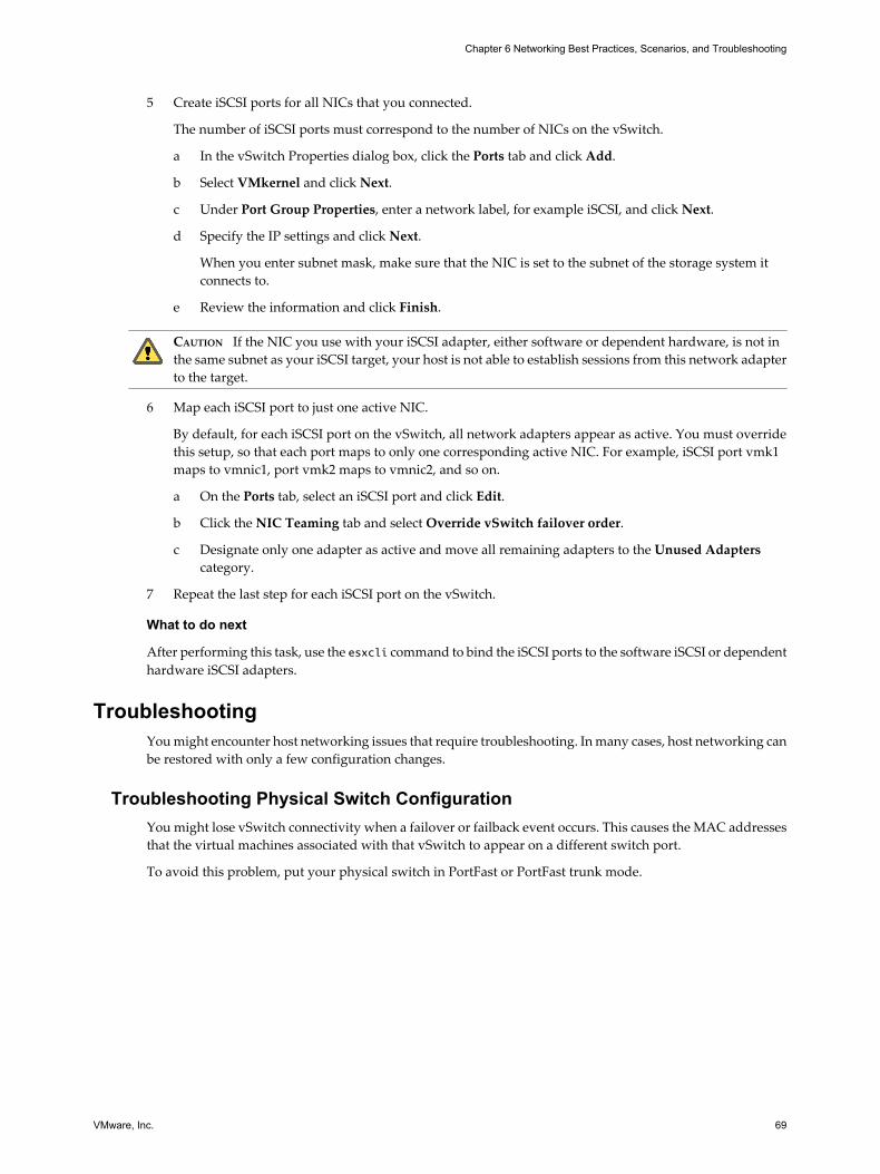
5 Create iSCSI ports for all NICs that you connected.
The number of iSCSI ports must correspond to the number of NICs on the vSwitch.
a In the vSwitch Properties dialog box, click the Ports tab and click Add.
b Select VMkernel and click Next.
c Under Port Group Properties, enter a network label, for example iSCSI, and click Next.
d Specify the IP settings and click Next.
When you enter subnet mask, make sure that the NIC is set to the subnet of the storage system itconnects to.
e Review the information and click Finish.
CAUTION If the NIC you use with your iSCSI adapter, either software or dependent hardware, is not inthe same subnet as your iSCSI target, your host is not able to establish sessions from this network adapterto the target.
6 Map each iSCSI port to just one active NIC.
By default, for each iSCSI port on the vSwitch, all network adapters appear as active. You must overridethis setup, so that each port maps to only one corresponding active NIC. For example, iSCSI port vmk1maps to vmnic1, port vmk2 maps to vmnic2, and so on.
a On the Ports tab, select an iSCSI port and click Edit.
b Click the NIC Teaming tab and select Override vSwitch failover order.
c Designate only one adapter as active and move all remaining adapters to the Unused Adapterscategory.
7 Repeat the last step for each iSCSI port on the vSwitch.
What to do next
After performing this task, use the esxcli command to bind the iSCSI ports to the software iSCSI or dependenthardware iSCSI adapters.
TroubleshootingYou might encounter host networking issues that require troubleshooting. In many cases, host networking canbe restored with only a few configuration changes.
Troubleshooting Physical Switch ConfigurationYou might lose vSwitch connectivity when a failover or failback event occurs. This causes the MAC addressesthat the virtual machines associated with that vSwitch to appear on a different switch port.
To avoid this problem, put your physical switch in PortFast or PortFast trunk mode.
Chapter 6 Networking Best Practices, Scenarios, and Troubleshooting
VMware, Inc. 69

Troubleshooting Port Group ConfigurationChanging the name of a port group when virtual machines are already connected to that port group causes aninvalid network configuration for the virtual machines that are configured to connect to that port group.
The connection from virtual network adapters to port groups is made by name, and the name is the identifierthat is stored in the virtual machine configuration. Changing the name of a port group does not cause a massreconfiguration of all the virtual machines connected to that port group. Virtual machines that are alreadypowered on continue to function until they are powered off, because their connections to the network arealready established.
Avoid renaming networks after they are in use. After you rename a port group, you must reconfigure eachassociated virtual machine to reflect the new port group name.
ESXi Configuration Guide
70 VMware, Inc.

Storage
VMware, Inc. 71

ESXi Configuration Guide
72 VMware, Inc.

Introduction to Storage 7This introduction describes available storage options for ESXi and explains how to configure your ESXi systemso that it can use and manage different types of storage.
This chapter includes the following topics:
n “About ESXi Storage,” on page 73
n “Types of Physical Storage,” on page 74
n “Supported Storage Adapters,” on page 75
n “Target and Device Representations,” on page 75
n “About ESXi Datastores,” on page 77
n “Comparing Types of Storage,” on page 80
n “Displaying Storage Adapters,” on page 81
n “Viewing Storage Devices,” on page 82
n “Displaying Datastores,” on page 83
About ESXi StorageESXi storage refers to the storage space on a variety of physical storage systems, local or networked, that a hostuses to store virtual machine disks.
A virtual machine uses a virtual hard disk to store its operating system, program files, and other data associatedwith its activities. A virtual disk is a large physical file, or a set of files, that can be copied, moved, archived,and backed up as easily as any other file. To store virtual disk files and manipulate the files, a host requiresdedicated storage space.
The host uses storage space on a variety of physical storage systems, including your host’s internal and externaldevices, or networked storage, dedicated to the specific tasks of storing and protecting data.
The host can discover storage devices to which it has access and format them as datastores. The datastore is aspecial logical container, analogous to a file system, where ESXi places virtual disk files and other files thatencapsulate essential components of a virtual machine. Deployed on different storage devices, the datastoreshide specifics of each storage device and provide a uniform model for storing virtual machine files.
Using the vSphere Client, you can set up datastores on any storage device that your host discovers. In addition,you can use folders to create logical groups of datastores for organizational purposes, and for settingpermissions and alarms across the datastore group.
VMware, Inc. 73

Types of Physical StorageThe ESXi storage management process starts with storage space that your storage administrator preallocateson different storage systems.
ESXi supports the following types of storage:
Local Storage Stores virtual machine files on internal or directly connected external storagedisks.
Networked Storage Stores virtual machine files on external storage disks or arrays attached to yourhost through a direct connection or through a high-speed network.
Local StorageLocal storage can be internal hard disks located inside your ESXi host, or it can be external storage systemslocated outside and connected to the host directly through protocols such as SAS or SATA.
Local storage does not require a storage network to communicate with your host. You need is a cable connectedto the storage unit and, when required, a compatible HBA in your host.
ESXi supports a variety of internal or external local storage devices, including SCSI, IDE, SATA, USB, and SASstorage systems. Regardless of the type of storage you use, your host hides a physical storage layer from virtualmachines.
NOTE You cannot use IDE/ATA drives to store virtual machines.
Local storage devices do not support sharing across multiple hosts. A datastore on a local storage device canbe accessed by only one host.
Because the majority of local storage devices do not support multiple connections, you cannot use multiplepaths to access local storage.
Networked StorageNetworked storage consists of external storage systems that your ESXi host uses to store virtual machine filesremotely. Typically, the host accesses these systems over a high-speed storage network.
Networked storage devices are shared. Datastores on networked storage devices can be accessed by multiplehosts concurrently. ESXi supports the following networked storage technologies.
NOTE Accessing the same storage through different transport protocols, such as iSCSI and Fibre Channel, atthe same time is not supported.
Fibre Channel (FC) Stores virtual machine files remotely on an FC storage area network (SAN). FCSAN is a specialized high-speed network that connects your hosts to high-performance storage devices. The network uses Fibre Channel protocol totransport SCSI traffic from virtual machines to the FC SAN devices.
ESXi Configuration Guide
74 VMware, Inc.

To connect to the FC SAN, your host should be equipped with Fibre Channelhost bus adapters (HBAs). Unless you use Fibre Channel direct connect storage,you need Fibre Channel switches to route storage traffic. If your host containsFCoE (Fibre Channel over Ethernet) HBAs, you can connect to your sharedFibre Channel devices using an IP network.
Internet SCSI (iSCSI) Stores virtual machine files on remote iSCSI storage devices. iSCSI packagesSCSI storage traffic into the TCP/IP protocol so that it can travel throughstandard TCP/IP networks instead of the specialized FC network. With an iSCSIconnection, your host serves as the initiator that communicates with a target,located in remote iSCSI storage systems.
ESXi offers the following types of iSCSI connections:
Hardware iSCSI Your host connects to storage through a third-partyadapter capable of offloading the iSCSI and networkprocessing.
Software iSCSI Your host uses a software-based iSCSI initiator in theVMkernel to connect to storage. With this type of iSCSIconnection, your host needs only a standard networkadapter for network connectivity.
Network-attachedStorage (NAS)
Stores virtual machine files on remote file servers accessed over a standardTCP/IP network. The NFS client built into ESXi uses Network File System (NFS)protocol version 3 to communicate with the NAS/NFS servers. For networkconnectivity, the host requires a standard network adapter.
Shared Serial AttachedSCSI (SAS)
Stores virtual machines on direct-attached SAS storage systems that offershared access to multiple hosts. This type of access permits multiple hosts toaccess the same VMFS datastore on a LUN.
Supported Storage AdaptersStorage adapters provide connectivity for your ESXi host to a specific storage unit or network.
Depending on the type of storage you use, you might need to install or enable a storage adapter on your host.ESXi supports different classes of adapters, including SCSI, iSCSI, RAID, Fibre Channel, Fibre Channel overEthernet (FCoE), and Ethernet. ESXi accesses the adapters directly through device drivers in the VMkernel.
Target and Device RepresentationsIn the ESXi context, the term target identifies a single storage unit that the host can access. The terms deviceand LUN describe a logical volume that represents storage space on a target. Typically, the terms device andLUN, in the ESXi context, mean a SCSI volume presented to the host from a storage target and available forformatting.
Different storage vendors present the storage systems to ESXi hosts in different ways. Some vendors presenta single target with multiple storage devices or LUNs on it, while others present multiple targets with oneLUN each.
Figure 7-1. Target and LUN Representations
storage array
target
LUN LUN LUN
storage array
target target target
LUN LUN LUN
Chapter 7 Introduction to Storage
VMware, Inc. 75

In this illustration, three LUNs are available in each configuration. In one case, the host sees one target, butthat target has three LUNs that can be used. Each LUN represents an individual storage volume. In the otherexample, the host sees three different targets, each having one LUN.
Targets that are accessed through the network have unique names that are provided by the storage systems.The iSCSI targets use iSCSI names, while Fibre Channel targets use World Wide Names (WWNs).
NOTE ESXi does not support accessing the same LUN through different transport protocols, such as iSCSI andFibre Channel.
A device, or LUN, is identified by its UUID name. If a LUN is shared by multiple hosts, it must be presentedto all host with the same UUID.
Understanding Fibre Channel NamingIn Fibre Channel SAN, a World Wide Name (WWN) uniquely identifies each element in the network, such asa Fibre Channel adapter or storage device.
The WWN is a 64-bit address that consists of 16 hexadecimal numbers and might look like this:
20:00:00:e0:8b:8b:38:77 21:00:00:e0:8b:8b:38:77
The WWN is assigned to every Fibre Channel SAN element by its manufacturer.
Understanding iSCSI Naming and AddressingIn an iSCSI network, each iSCSI element that uses the network has a unique and permanent iSCSI name andis assigned an address for access.
iSCSI NameIdentifies a particular iSCSI element, regardless of its physical location. The iSCSI name can use IQN or EUIformat.
n IQN (iSCSI qualified name). Can be up to 255 characters long and has the following format:
iqn.yyyy-mm.naming-authority:unique name
yyyy-mm The year and month when the naming authority was established.
naming-authority Usually reverse syntax of the Internet domain name of the namingauthority. For example, the iscsi.vmware.com naming authority could havethe iSCSI qualified name form of iqn.1998-01.com.vmware.iscsi. The nameindicates that the vmware.com domain name was registered in January of1998, and iscsi is a subdomain, maintained by vmware.com.
unique name Any name you want to use, for example, the name of your host. The namingauthority must make sure that any names assigned following the colon areunique. For example, iqn.1998-01.com.vmware.iscsi:name1.
n EUI (extended unique identifier). Includes the eui. prefix, followed by the 16-character name. The nameincludes 24 bits for the company name assigned by the IEEE and 40 bits for a unique ID, such as a serialnumber.
For example,
eui.0123456789ABCDEF
iSCSI AliasA more manageable, easy-to-remember name to use instead of the iSCSI name. iSCSI aliases are not unique,and are intended to be just a friendly name to associate with the node.
ESXi Configuration Guide
76 VMware, Inc.

IP AddressAn address associated with each iSCSI element so that routing and switching equipment on the network canestablish the connection between different elements, such as the host and storage. This is just like the IP addressyou assign to a computer to get access to your company's network or the Internet.
Understanding Storage Device NamingIn the vSphere Client, each storage device, or LUN, is identified by several names, including a friendly name,a UUID, and a runtime name.
NameThis is a friendly name that the ESXi host assigns to a device based on the storage type and manufacturer. Youcan modify the name using the vSphere Client. When you modify the name of the device on one host, thechange takes affect across all hosts that have access to this device.
IdentifierThis is a universally unique identifier assigned to a device. Depending on the type of storage, differentalgorithms are used to create the identifier. The identifier is persistent across reboots and must be the same forall hosts sharing the device.
Runtime NameThis is the name of the first path to the device. The runtime name is created by the host, is not a reliable identifierfor the device, and is not persistent.
The runtime name has the following format: vmhba#:C#:T#:L#.
vmhba# The name of the storage adapter. The name refers to the physical adapter onthe host, not to the SCSI controller used by the virtual machines.
C# The storage channel number. Software iSCSI initiators use the channel numberto show multiple paths to the same target.
T# The target number. Target numbering is decided by the host and might changeif there is a change in the mappings of targets visible to the host. Targets thatare shared by different ESXi hosts might not have the same target number.
L# The LUN number that shows the position of the LUN within the target. TheLUN number is provided by the storage system. If a target has only one LUN,the LUN number is always zero (0).
For example, vmhba1:C0:T3:L1 represents LUN1 on target 3 accessed through the storage adapter vmhba1 andchannel 0.
About ESXi DatastoresDatastores are logical containers, analogous to file systems, that hide specifics of each storage device andprovide a uniform model for storing virtual machine files. Datastores can also be used for storing ISO images,virtual machine templates, and floppy images.
You use the vSphere Client to access different types of storage devices that your ESXi host discovers and todeploy datastores on them.
Chapter 7 Introduction to Storage
VMware, Inc. 77

Depending on the type of storage you use, datastores can be backed by the following file system formats:
Virtual Machine FileSystem (VMFS)
High-performance file system optimized for storing virtual machines. Yourhost can deploy a VMFS datastore on any SCSI-based local or networkedstorage device, including Fibre Channel and iSCSI SAN equipment.
As an alternative to using the VMFS datastore, your virtual machine can havedirect access to raw devices and use a mapping file (RDM) as a proxy.
Network File System(NFS)
File system on a NAS storage device. ESXi supports NFS version 3 over TCP/IP.The host can access a designated NFS volume located on an NFS server, mountthe volume, and use it for any storage needs.
VMFS DatastoresESXi can format SCSI-based storage devices as VMFS datastores. VMFS datastores primarily serve asrepositories for virtual machines.
You can store multiple virtual machines on the same VMFS volume. Each virtual machine, encapsulated in aset of files, occupies a separate single directory. For the operating system inside the virtual machine, VMFSpreserves the internal file system semantics, which ensures correct application behavior and data integrity forapplications running in virtual machines.
In addition, you can use the VMFS datastores to store other files, such as virtual machine templates and ISOimages.
VMFS supports the following file and block sizes, enabling your virtual machines to run even the most data-intensive applications, including databases, ERP, and CRM, in virtual machines:
n Maximum virtual disk size: 2TB with 8MB block size
n Maximum file size: 2TB with 8MB block size
n Block size: 1MB (default), 2MB, 4MB, and 8MB
Creating and Increasing VMFS DatastoresYou can set up VMFS datastores on any SCSI-based storage devices that your ESXi host discovers. After youcreate the VMFS datastore, you can edit its properties.
You can have up to 256 VMFS datastores per system, with a minimum volume size of 1.2GB.
NOTE Always have only one VMFS datastore for each LUN.
If your VMFS datastore requires more space, you can increase the VMFS volume. You can dynamically addnew extents to any VMFS datastore and grow the datastore up to 64TB. An extent is a LUN or partition on aphysical storage device. The datastore can stretch over multiple extents, yet appear as a single volume.
Another option is to grow the existing datastore extent if the storage device where your datastore resides hasfree space. You can grow the extent up to 2 TB.
ESXi Configuration Guide
78 VMware, Inc.

Sharing a VMFS Volume Across ESXi HostsAs a cluster file system, VMFS lets multiple ESXi hosts access the same VMFS datastore concurrently. You canconnect up to 32 hosts to a single VMFS volume.
Figure 7-2. Sharing a VMFS Volume Across Hosts
VMFS volume
hostA
hostB
hostC
virtualdiskfiles
VM1 VM2 VM3
disk1
disk2
disk3
To ensure that the same virtual machine is not accessed by multiple servers at the same time, VMFS provideson-disk locking.
Sharing the same VMFS volume across multiple hosts offers the following advantages:
n You can use VMware Distributed Resource Scheduling and VMware High Availability.
You can distribute virtual machines across different physical servers. That means you run a mix of virtualmachines on each server so that not all experience high demand in the same area at the same time. If aserver fails, you can restart virtual machines on another physical server. In case of a failure, the on-disklock for each virtual machine is released.
n You can use vMotion to migrate running virtual machines from one physical server to another.
n You can use VMware Consolidated Backup, which lets a proxy server, called VCB proxy, back up asnapshot of a virtual machine while the virtual machine is powered on and is reading and writing to itsstorage.
NFS DatastoreESXi can access a designated NFS volume located on a NAS server, mount the volume, and use it for its storageneeds. You can use NFS volumes to store and boot virtual machines in the same way that you use VMFSdatastores.
ESXi supports the following shared storage capabilities on NFS volumes:
n vMotion
n VMware DRS and VMware HA
n ISO images, which are presented as CD-ROMs to virtual machines
n Virtual machine snapshots
Chapter 7 Introduction to Storage
VMware, Inc. 79
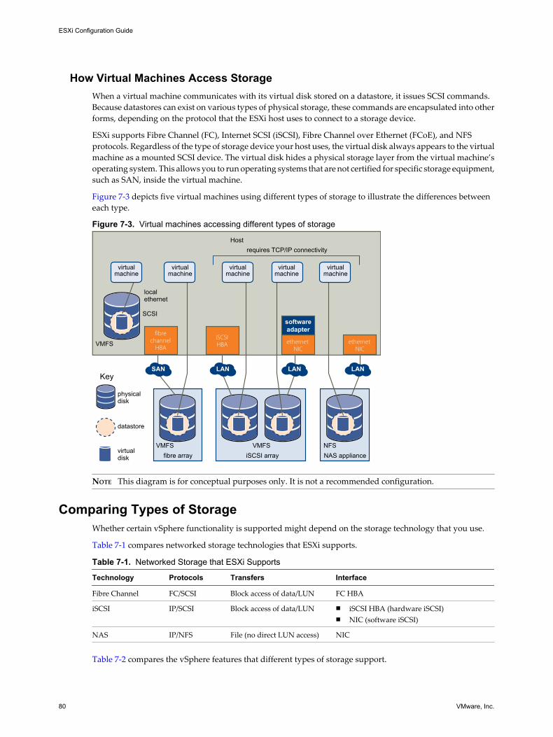
How Virtual Machines Access StorageWhen a virtual machine communicates with its virtual disk stored on a datastore, it issues SCSI commands.Because datastores can exist on various types of physical storage, these commands are encapsulated into otherforms, depending on the protocol that the ESXi host uses to connect to a storage device.
ESXi supports Fibre Channel (FC), Internet SCSI (iSCSI), Fibre Channel over Ethernet (FCoE), and NFSprotocols. Regardless of the type of storage device your host uses, the virtual disk always appears to the virtualmachine as a mounted SCSI device. The virtual disk hides a physical storage layer from the virtual machine’soperating system. This allows you to run operating systems that are not certified for specific storage equipment,such as SAN, inside the virtual machine.
Figure 7-3 depicts five virtual machines using different types of storage to illustrate the differences betweeneach type.
Figure 7-3. Virtual machines accessing different types of storage
iSCSI array NAS appliancefibre array
Host
VMFS
localethernet
SCSI
VMFS VMFS NFS
virtualmachine
virtualmachine
virtualmachine
virtualmachine
virtualmachine
SAN LAN LAN LAN
iSCSI HBA
fibrechannel
HBAethernet
NICethernet
NIC
softwareadapter
requires TCP/IP connectivity
Key
physicaldisk
datastore
virtualdisk
NOTE This diagram is for conceptual purposes only. It is not a recommended configuration.
Comparing Types of StorageWhether certain vSphere functionality is supported might depend on the storage technology that you use.
Table 7-1 compares networked storage technologies that ESXi supports.
Table 7-1. Networked Storage that ESXi Supports
Technology Protocols Transfers Interface
Fibre Channel FC/SCSI Block access of data/LUN FC HBA
iSCSI IP/SCSI Block access of data/LUN n iSCSI HBA (hardware iSCSI)n NIC (software iSCSI)
NAS IP/NFS File (no direct LUN access) NIC
Table 7-2 compares the vSphere features that different types of storage support.
ESXi Configuration Guide
80 VMware, Inc.

Table 7-2. vSphere Features Supported by Storage
Storage Type Boot VM vMotion Datastore RDMVMware HAand DRS VCB
Local Storage Yes No VMFS No No Yes
Fibre Channel Yes Yes VMFS Yes Yes Yes
iSCSI Yes Yes VMFS Yes Yes Yes
NAS over NFS Yes Yes NFS No Yes Yes
See Setup for Failover Clustering and Microsoft Cluster Service for support information concerning Microsoftclustering.
Displaying Storage AdaptersThe host uses storage adapters to access different storage devices. You can display the available storageadapters and review their information.
Table 7-3 lists information that you can see when you display details for each adapter. Certain adapters, forexample iSCSI, need to be configured or enabled before you can view their information.
Table 7-3. Storage Adapter Information
Adapter Information Description
Model Model of the adapter.
Targets (Fibre Channel andSCSI)
Number of targets accessed through the adapter.
Connected Targets (iSCSI) Number of connected targets on an iSCSI adapter.
WWN (Fibre Channel) World Wide Name formed according to Fibre Channel standards that uniquely identifiesthe FC adapter.
iSCSI Name (iSCSI) Unique name formed according to iSCSI standards that identifies the iSCSI adapter.
iSCSI Alias (iSCSI) A friendly name used instead of the iSCSI name.
IP Address (hardware iSCSI) Address assigned to the iSCSI adapter.
Discovery Methods (iSCSI) Discovery methods the iSCSI adapter uses to access iSCSI targets.
Devices All storage devices or LUNs the adapter can access.
Paths All paths the adapter uses to access storage devices.
View Storage Adapters InformationYou can display storage adapters that your host uses and review their information.
Procedure
1 In Inventory, select Hosts and Clusters.
2 Select a host and click the Configuration tab.
3 In Hardware, select Storage Adapters.
4 To view details for a specific adapter, select the adapter from the Storage Adapters list.
5 To list all storage devices the adapter can access, click Devices.
6 To list all paths the adapter uses, click Paths.
Chapter 7 Introduction to Storage
VMware, Inc. 81

Copy Storage Adapter Identifiers to the ClipboardIf your storage adapters use unique identifiers, such as an iSCSI Name or WWN, you can copy them to aclipboard directly from the UI.
Procedure
1 In Inventory, select Hosts and Clusters.
2 Select a host and click the Configuration tab.
3 In Hardware, select Storage Adapters.
4 Select the adapter from the Storage Adapters list.
5 In the Details panel, highlight the value in the name field, and select Copy from the right-button menu.
Viewing Storage DevicesYou can display all storage devices or LUNs available to the host, including all local and networked devices.If you use third-party multipathing plug-ins, the storage devices available through the plug-ins also appearon the list.
For each storage adapter, you can display a separate list of storage devices available for this adapter.
Generally, when you review storage devices, you see the following information.
Table 7-4. Storage Device Information
Storage Device Information Description
Name A friendly name that the ESXi host assigns to the device based on the storage type andmanufacturer. You can change this name to a name of your choice.
Identifier A universally unique identifier that is intrinsic to the device.
Runtime Name The name of the first path to the device.
LUN The LUN number that shows the position of the LUN within the target.
Type Type of device, for example, disk or CD-ROM.
Transport Transportation protocol your host uses to access the device.
Capacity Total capacity of the storage device.
Owner The plug-in, such as the NMP or a third-party plug-in, that the host uses to manage thestorage device.
Hardware Acceleration Information about whether the storage device assists the host with virtual machinemanagement operations. The status can be Supported, Not Supported, or Unknown. Fordetails, see “Storage Hardware Acceleration,” on page 119.
Location A path to the storage device in the /vmfs/devices/ directory.
Partitions Primary and logical partitions, including a VMFS datastore, if configured.
Display Storage Devices for a HostYou can display all storage devices or LUNs available to a host. If you use any third-party multipathing plug-ins, the storage devices available through the plug-ins also appear on the list.
Procedure
1 In Inventory, select Hosts and Clusters.
2 Select a host and click the Configuration tab.
ESXi Configuration Guide
82 VMware, Inc.

3 In Hardware, select Storage.
4 Click Devices.
5 To view additional details about a specific device, select the device from the list.
Display Storage Devices for an AdapterYou can display a list of storage devices accessible to a specific storage adapter on the host.
Procedure
1 In Inventory, select Hosts and Clusters.
2 Select a host and click the Configuration tab.
3 In Hardware, select Storage Adapters.
4 Select the adapter from the Storage Adapters list.
5 Click Devices.
Copy Storage Device Identifiers to the ClipboardA storage device identifier is a universally unique ID assigned to a storage device or LUN. Depending on thetype of storage, different algorithms are used to create the identifier and it can be long and complex. You cancopy the storage device identifier directly from the UI.
Procedure
1 Display a list of storage devices.
2 Right-click a device and select Copy identifier to clipboard.
Displaying DatastoresYou can display all datastores available to your hosts and analyze their properties.
Datastores are added to the vSphere Client in the following ways:
n Created on an available storage device.
n Discovered when a host is added to the inventory. When you add a host to the inventory, the vSphereClient displays any datastores available to the host.
If your vSphere Client is connected to a vCenter Server system, you can see datastore information in theDatastores view. This view displays all datastores in the inventory, arranged by a datacenter. Through thisview, you can organize datastores into folder hierarchies, create datastores, edit their properties, or removeexisting datastores.
This view is comprehensive and shows all information for your datastores including hosts and virtual machinesusing the datastores, storage reporting information, permissions, alarms, tasks and events, storage topology,and storage reports. Configuration details for each datastore on all hosts connected to this datastore areprovided on the Configuration tab of the Datastores view.
NOTE The Datastores view is not available when the vSphere client connects directly to your host. In this case,review datastore information through the host storage configuration tab.
Table 7-5 describes the datastore details that you can see when you review datastores.
Chapter 7 Introduction to Storage
VMware, Inc. 83
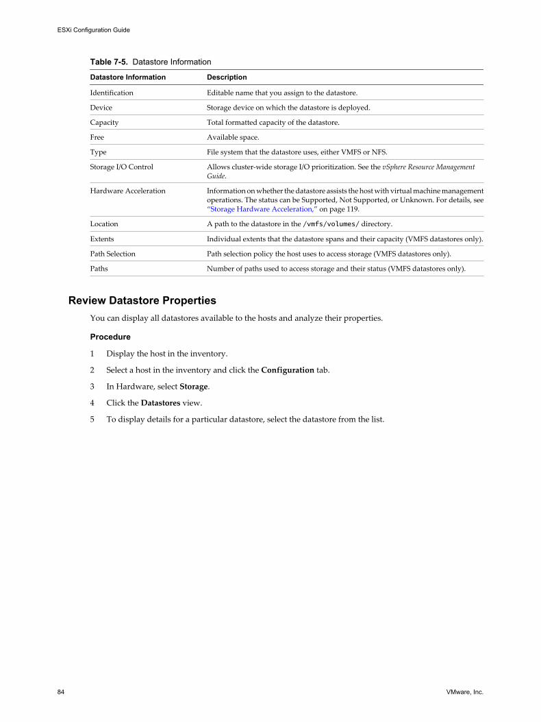
Table 7-5. Datastore Information
Datastore Information Description
Identification Editable name that you assign to the datastore.
Device Storage device on which the datastore is deployed.
Capacity Total formatted capacity of the datastore.
Free Available space.
Type File system that the datastore uses, either VMFS or NFS.
Storage I/O Control Allows cluster-wide storage I/O prioritization. See the vSphere Resource ManagementGuide.
Hardware Acceleration Information on whether the datastore assists the host with virtual machine managementoperations. The status can be Supported, Not Supported, or Unknown. For details, see“Storage Hardware Acceleration,” on page 119.
Location A path to the datastore in the /vmfs/volumes/ directory.
Extents Individual extents that the datastore spans and their capacity (VMFS datastores only).
Path Selection Path selection policy the host uses to access storage (VMFS datastores only).
Paths Number of paths used to access storage and their status (VMFS datastores only).
Review Datastore PropertiesYou can display all datastores available to the hosts and analyze their properties.
Procedure
1 Display the host in the inventory.
2 Select a host in the inventory and click the Configuration tab.
3 In Hardware, select Storage.
4 Click the Datastores view.
5 To display details for a particular datastore, select the datastore from the list.
ESXi Configuration Guide
84 VMware, Inc.

Configuring ESXi Storage 8The following topics contain information about configuring local SCSI storage devices, Fibre Channel SANstorage, iSCSI storage, and NFS storage.
This chapter includes the following topics:
n “Local SCSI Storage,” on page 85
n “Fibre Channel Storage,” on page 86
n “iSCSI Storage,” on page 86
n “Datastore Refresh and Storage Rescan Operations,” on page 99
n “Create VMFS Datastores,” on page 100
n “Network Attached Storage,” on page 101
n “Creating a Diagnostic Partition,” on page 103
Local SCSI StorageLocal storage uses a SCSI-based device such as your ESXi host’s hard disk or any external dedicated storagesystem connected directly to your host.
Figure 8-1 depicts a virtual machine using local SCSI storage.
Figure 8-1. Local Storage
Host
VMFS
localethernet
SCSI
virtualmachine
In this example of a local storage topology, the ESXi host uses a single connection to a disk. On that disk, youcan create a VMFS datastore, which you use to store virtual machine disk files.
VMware, Inc. 85

Although this storage configuration is possible, it is not a recommended topology. Using single connectionsbetween storage arrays and hosts creates single points of failure (SPOF) that can cause interruptions when aconnection becomes unreliable or fails.
To ensure fault tolerance, some DAS systems support redundant connection paths.
Fibre Channel StorageESXi supports Fibre Channel adapters, which allow a host to connect to a SAN and see storage devices on theSAN.
You must install Fibre Channel (FC) adapters before the host can access FC storage devices.
Figure 8-2 depicts virtual machines using Fibre Channel storage.
Figure 8-2. Fibre Channel Storage
fibre array
VMFS
virtualmachine
SAN
fibrechannel
HBA
Host
In this configuration, an ESXi host connects to SAN fabric, which consists of Fibre Channel switches and storagearrays, using a Fibre Channel adapter. LUNs from a storage array become available to the host. You can accessthe LUNs and create a datastore for your storage needs. The datastore uses the VMFS format.
For specific information on setting up the FC SAN fabric and storage arrays to work with ESXi, see the FibreChannel SAN Configuration Guide.
iSCSI StorageESXi supports iSCSI technology that allows your host to use an IP network while accessing remote storage.With iSCSI, SCSI storage commands that your virtual machine issues to its virtual disk are converted intoTCP/IP packets and transmitted to a remote device, or target, that stores the virtual disk.
To access remote targets, the host uses iSCSI initiators. Initiators transport SCSI requests and responses betweenthe host and the target storage device on the IP network. ESXi supports hardware, dependent and independent,and software iSCSI initiators.
You must configure iSCSI initiators for the host to access and display iSCSI storage devices.
Figure 8-3 depicts different types of iSCSI initiators.
ESXi Configuration Guide
86 VMware, Inc.

Figure 8-3. iSCSI Storage
iSCSI array
VMFS
virtualmachine
virtualmachine
LAN LAN
iSCSI HBA ethernet
NIC
Host
softwareadapter
In the left example, the host uses the hardware iSCSI adapter to connect to the iSCSI storage system.
In the right example, the host uses a software iSCSI adapter and an Ethernet NIC to connect to the iSCSI storage.
iSCSI storage devices from the storage system become available to the host. You can access the storage devicesand create VMFS datastores for your storage needs.
For specific information on setting up the iSCSI SAN to work with ESXi, see the iSCSI SAN ConfigurationGuide.
iSCSI InitiatorsTo access iSCSI targets, your host uses iSCSI initiators. The initiators transport SCSI requests and responses,encapsulated into the iSCSI protocol, between the host and the iSCSI target.
VMware supports different types of initiators.
Software iSCSI AdapterA software iSCSI adapter is a VMware code built into the VMkernel. It allows your host to connect to the iSCSIstorage device through standard network adapters. The software iSCSI adapter handles iSCSI processing whilecommunicating with the network adapter. With the software iSCSI adapter, you can use iSCSI technologywithout purchasing specialized hardware.
Hardware iSCSI AdapterA hardware iSCSI adapter is a third-party adapter that offloads iSCSI and network processing from your host.Hardware iSCSI adapters are divided into categories.
Dependent HardwareiSCSI Adapter
Depends on VMware networking, and iSCSI configuration and managementinterfaces provided by VMware.
Chapter 8 Configuring ESXi Storage
VMware, Inc. 87

This type of adapter can be a card that presents a standard network adapterand iSCSI offload functionality for the same port. The iSCSI offloadfunctionality depends on the host's network configuration to obtain the IP,MAC, and other parameters used for iSCSI sessions. An example of adependent adapter is the iSCSI licensed Broadcom 5709 NIC.
Independent HardwareiSCSI Adapter
Implements its own networking and iSCSI configuration and managementinterfaces.
An example of an independent hardware iSCSI adapter is a card that eitherpresents only iSCSI offload functionality or iSCSI offload functionality andstandard NIC functionality. The iSCSI offload functionality has independentconfiguration management that assigns the IP, MAC, and other parametersused for the iSCSI sessions. An example of a independent adapter is the QLogicQLA4052 adapter.
Hardware iSCSI adapters might need to be licensed. Otherwise, they will not appear in the vSphere Client orvSphere CLI. Contact your vendor for licensing information.
Setting Up Independent Hardware iSCSI AdaptersAn independent hardware iSCSI adapter is a specialized third-party adapter capable of accessing iSCSI storageover TCP/IP. This iSCSI adapter handles all iSCSI and network processing and management for your ESXisystem.
The setup and configuration process for the independent hardware iSCSI adapters involves these steps:
1 Check whether the adapter needs to be licensed.
See your vendor documentation.
2 Install the adapter.
For installation information, see vendor documentation.
3 Verity that the adapter is installed correctly.
See “View Independent Hardware iSCSI Adapters,” on page 88.
4 Configure discovery addresses.
See “Configuring Discovery Addresses for iSCSI Initiators,” on page 93.
5 Configure CHAP parameters.
See “Configuring CHAP Parameters for iSCSI Adapters,” on page 94.
For your host to be able to access iSCSI storage, you must first install the hardware iSCSI adapter and configurediscovery address and CHAP parameters.
View Independent Hardware iSCSI AdaptersView a hardware iSCSI adapter to verify that it is correctly installed and ready for configuration.
Prerequisites
After you install a hardware iSCSI adapter, it appears on the list of storage adapters available for configuration.You can view its properties.
Required privilege: Host.Configuration.Storage Partition Configuration
Procedure
1 Log in to the vSphere Client, and select a host from the inventory panel.
ESXi Configuration Guide
88 VMware, Inc.

2 Click the Configuration tab and click Storage Adapters in the Hardware panel.
If installed, the hardware iSCSI initiator should appear on the list of storage adapters.
3 Select the initiator to view.
The default details for the initiator appear, including the model, iSCSI name, iSCSI alias, IP address, andtarget and paths information.
4 Click Properties.
The iSCSI Initiator Properties dialog box appears. The General tab displays additional characteristics ofthe initiator.
You can now configure your hardware initiator or change its default characteristics.
Change Name and IP Address for Independent Hardware InitiatorsWhen you configure your independent hardware iSCSI initiators, make sure that their names and IP addressesare formatted properly.
Procedure
1 Access the iSCSI Initiator Properties dialog box.
2 Click Configure.
3 To change the default iSCSI name for your initiator, enter the new name.
Make sure the name you enter is worldwide unique and properly formatted or some storage devices mightnot recognize the hardware iSCSI initiator.
4 (Optional) Enter the iSCSI alias.
The alias is a name that you use to identify the hardware iSCSI initiator.
5 Change the default IP settings.
You must change the default IP settings so that they are configured properly for the IP SAN. Work withyour network administrator to determine the IP setting for the HBA.
6 Click OK to save your changes.
If you change the iSCSI name, it is used for new iSCSI sessions. For existing sessions, new settings are not useduntil logout and re-login.
Setting Up and Configuring Software iSCSI AdapterWith the software-based iSCSI implementation, you can use standard NICs to connect your host to a remoteiSCSI target on the IP network. The software iSCSI adapter that is built into ESXi facilitates this connection bycommunicating with the physical NICs through the network stack.
When you connect to a vCenter Server or a host with the vSphere Client, you can see the software iSCSI adapteron the list of your storage adapters. Only one software iSCSI adapter appears. Before you can use the softwareiSCSI adapter, you must set up networking, enable the adapter, and configure parameters such as discoveryaddresses and CHAP. The software iSCSI adapter configuration workflow includes these steps:
1 Configure the iSCSI networking by creating ports for iSCSI traffic.
See “Networking Configuration for Software iSCSI and Dependent Hardware iSCSI,” on page 66.
2 Enable the software iSCSI adapter.
See “Enable the Software iSCSI Adapter,” on page 90.
Chapter 8 Configuring ESXi Storage
VMware, Inc. 89

3 If you use multiple NICs for the software iSCSI multipathing, perform the port binding by connecting alliSCSI ports to the software iSCSI adapter.
See “Bind iSCSI Ports to iSCSI Adapters,” on page 92.
4 If needed, enable Jumbo Frames. Jumbo Frames must be enabled for each vSwitch through the vSphereCLI.
See the Networking section for more information.
5 Configure discovery addresses.
See “Configuring Discovery Addresses for iSCSI Initiators,” on page 93.
6 Configure CHAP parameters.
See “Configuring CHAP Parameters for iSCSI Adapters,” on page 94.
Enable the Software iSCSI AdapterYou must enable your software iSCSI adapter so that your host can use it to access iSCSI storage.
Prerequisites
Before enabling the software iSCSI adapter, set up networking for iSCSI.
NOTE If you boot from iSCSI using the software iSCSI adapter, the adapter is enabled and the networkconfiguration is created automatically at the first boot. If you disable the adapter, it is re-enabled each timeyou boot the host.
Procedure
1 Log in to the vSphere Client, and select a server from the inventory panel.
2 Click the Configuration tab and click Storage Adapters in the Hardware panel.
The list of available storage adapters appears.
3 Select the iSCSI initiator to configure and click Properties.
4 Click Configure.
5 To enable the initiator, select Enabled and click OK.
After you enable the initiator, the host assigns the default iSCSI name to it. You can change the default nameif needed.
Setting Up and Configuring Dependent Hardware iSCSI AdaptersA dependent hardware iSCSI adapter is a third-party adapter that depends on VMware networking, and iSCSIconfiguration and management interfaces provided by VMware.
This type of adapter can be a card, such as a Broadcom 5709 NIC, that presents a standard network adapterand iSCSI offload functionality for the same port. The iSCSI offload functionality appears on the list of storageadapters as an iSCSI adapter. Although the iSCSI adapter is enabled by default, to make it functional, you mustset up networking for the iSCSI traffic and bind the adapter and an appropriate VMkernel iSCSI port. You canthen configure the adapter.
The entire setup and configuration process for the dependent hardware iSCSI adapters involves these steps:
1 View the dependent hardware adapters.
See “View Dependent Hardware iSCSI Adapters,” on page 91.
If your dependent hardware adapters do not appear on the list of storage adapters, check whether theyneed to be licensed. See your vendor documentation.
ESXi Configuration Guide
90 VMware, Inc.

2 Determine the association between the dependent hardware adapters and physical NICs.
See “Determine Association Between Dependent Hardware iSCSI and Physical Network Adapters,” onpage 92
Make sure to note the names of the corresponding physical NICs. For example, the vmhba33 adaptercorresponds to vmnic1 and vmhba34 corresponds to vmnic2.
3 Configure the iSCSI networking by creating ports for the iSCSI traffic.
See “Networking Configuration for Software iSCSI and Dependent Hardware iSCSI,” on page 66.
Open a port for each NIC. For example, create the vmk1 port for the vmnic1 NIC and the vmk2 port forvmnic2.
4 Bind the iSCSI ports to corresponding dependent hardware iSCSI adapters. This step is necessary nomatter whether you have multiple adapters or just one.
See “Bind iSCSI Ports to iSCSI Adapters,” on page 92.
In this example, you bind port vmk1 to vmhba33 and port vmk2 to vmhba34.
5 Configure discovery addresses.
See “Configuring Discovery Addresses for iSCSI Initiators,” on page 93.
6 Configure CHAP parameters.
See “Configuring CHAP Parameters for iSCSI Adapters,” on page 94.
Dependent Hardware iSCSI ConsiderationsWhen you use dependent hardware iSCSI adapters with ESXi, certain considerations apply.
n When you use any dependent hardware iSCSI adapter, performance reporting for a NIC associated withthe adapter might show little or no activity, even when iSCSI traffic is heavy. This behavior occurs becausethe iSCSI traffic bypasses the regular networking stack.
n The Broadcom iSCSI adapter performs data reassembly in hardware, which has a limited buffer space.When you use the Broadcom iSCSI adapter in a congested network or under load, enable flow control toavoid performance degradation.
Flow control manages the rate of data transmission between two nodes to prevent a fast sender fromoverrunning a slow receiver. For best results, enable flow control at the end points of the I/O path, at thehosts and iSCSI storage systems.
n Broadcom iSCSI adapters do not support IPv6 and Jumbo Frames.
View Dependent Hardware iSCSI AdaptersView a dependent hardware iSCSI adapter to verify that it is correctly loaded.
If the dependent hardware adapter does not appear on the list of storage adapters, check whether it needs tobe licensed. See your vendor documentation.
Procedure
1 Log in to the vSphere Client, and select a host from the Inventory panel.
2 Click the Configuration tab and click Storage Adapters in the Hardware panel.
If installed, the dependent hardware iSCSI adapter should appear on the list of storage adapters.
3 Select the adapter to view and click Properties.
The iSCSI Initiator Properties dialog box displays the default details for the adapter, including the iSCSIname and iSCSI alias.
Chapter 8 Configuring ESXi Storage
VMware, Inc. 91
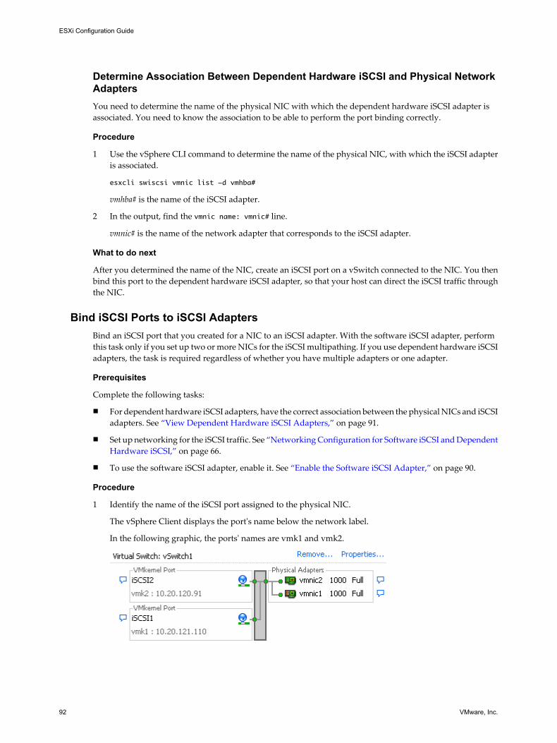
Determine Association Between Dependent Hardware iSCSI and Physical NetworkAdaptersYou need to determine the name of the physical NIC with which the dependent hardware iSCSI adapter isassociated. You need to know the association to be able to perform the port binding correctly.
Procedure
1 Use the vSphere CLI command to determine the name of the physical NIC, with which the iSCSI adapteris associated.
esxcli swiscsi vmnic list -d vmhba#
vmhba# is the name of the iSCSI adapter.
2 In the output, find the vmnic name: vmnic# line.
vmnic# is the name of the network adapter that corresponds to the iSCSI adapter.
What to do next
After you determined the name of the NIC, create an iSCSI port on a vSwitch connected to the NIC. You thenbind this port to the dependent hardware iSCSI adapter, so that your host can direct the iSCSI traffic throughthe NIC.
Bind iSCSI Ports to iSCSI AdaptersBind an iSCSI port that you created for a NIC to an iSCSI adapter. With the software iSCSI adapter, performthis task only if you set up two or more NICs for the iSCSI multipathing. If you use dependent hardware iSCSIadapters, the task is required regardless of whether you have multiple adapters or one adapter.
Prerequisites
Complete the following tasks:
n For dependent hardware iSCSI adapters, have the correct association between the physical NICs and iSCSIadapters. See “View Dependent Hardware iSCSI Adapters,” on page 91.
n Set up networking for the iSCSI traffic. See “Networking Configuration for Software iSCSI and DependentHardware iSCSI,” on page 66.
n To use the software iSCSI adapter, enable it. See “Enable the Software iSCSI Adapter,” on page 90.
Procedure
1 Identify the name of the iSCSI port assigned to the physical NIC.
The vSphere Client displays the port's name below the network label.
In the following graphic, the ports' names are vmk1 and vmk2.
ESXi Configuration Guide
92 VMware, Inc.

2 Use the vSphere CLI command to bind the iSCSI port to the iSCSI adapter.
esxcli swiscsi nic add -n port_name -d vmhba
IMPORTANT For software iSCSI, repeat this command for each iSCSI port connecting all ports with thesoftware iSCSI adapter. With dependent hardware iSCSI, make sure to bind each port to an appropriatecorresponding adapter.
3 Verify that the port was added to the iSCSI adapter.
esxcli swiscsi nic list -d vmhba
4 Use the vSphere Client to rescan the iSCSI adapter.
Configuring Discovery Addresses for iSCSI InitiatorsSet up target discovery addresses so that the iSCSI initiator can determine which storage resource on thenetwork is available for access.
The ESXi system supports these discovery methods:
Dynamic Discovery Also known as SendTargets discovery. Each time the initiator contacts aspecified iSCSI server, the initiator sends the SendTargets request to the server.The server responds by supplying a list of available targets to the initiator. Thenames and IP addresses of these targets appear on the Static Discovery tab. Ifyou remove a static target added by dynamic discovery, the target might bereturned to the list the next time a rescan happens, the HBA is reset, or the hostis rebooted.
Static Discovery The initiator does not have to perform any discovery. The initiator has a list oftargets it can contact and uses their IP addresses and target names tocommunicate with them.
Set Up Dynamic DiscoveryWith Dynamic Discovery, each time the initiator contacts a specified iSCSI server, it sends the SendTargetsrequest to the server. The server responds by supplying a list of available targets to the initiator.
When you set up Dynamic Discovery, you can only add a new iSCSI server. You cannot change the IP address,DNS name, or port number of an existing iSCSI server. To make changes, delete the existing server and add anew one.
Procedure
1 Log in to the vSphere Client and select a server from the inventory panel.
2 Click the Configuration tab and click Storage Adapters in the Hardware panel.
The list of available storage adapters appears.
3 Select the iSCSI initiator to configure and click Properties.
4 In the iSCSI Initiator Properties dialog box, click the Dynamic Discovery tab.
5 To add an address for the SendTargets discovery, click Add.
The Add SendTargets Server dialog box appears.
6 Enter the IP address or DNS name of the storage system and click OK.
After your host establishes the SendTargets session with this system, any newly discovered targets appearin the Static Discovery list.
Chapter 8 Configuring ESXi Storage
VMware, Inc. 93

7 To delete a specific SendTargets server, select it and click Remove.
After you remove a SendTargets server, it might still appear in the Inheritance field as the parent of statictargets. This entry indicates where the static targets were discovered and does not affect the functionality.
What to do next
After configuring Dynamic Discovery for your iSCSI adapter, rescan the adapter.
Set Up Static DiscoveryWith iSCSI initiators, in addition to the dynamic discovery method, you can use static discovery and manuallyenter information for the targets.
When you set up Static Discovery, you can only add iSCSI targets. You cannot change the IP address, DNSname, iSCSI target name, or port number of an existing target. To make changes, remove the existing targetand add a new one.
Procedure
1 Log in to the vSphere Client and select a server from the inventory panel.
2 Click the Configuration tab and click Storage Adapters in the Hardware panel.
The list of available storage adapters appears.
3 Select the iSCSI initiator to configure and click Properties.
4 In the iSCSI Initiator Properties dialog box, click the Static Discovery tab.
The tab displays all dynamically discovered targets and any static targets already entered.
5 To add a target, click Add and enter the target’s information.
6 To delete a specific target, select the target and click Remove.
What to do next
After configuring Static Discovery for your iSCSI adapter, rescan the adapter.
Configuring CHAP Parameters for iSCSI AdaptersBecause the IP networks that the iSCSI technology uses to connect to remote targets do not protect the datathey transport, you must ensure security of the connection. One of the protocols that iSCSI implements is theChallenge Handshake Authentication Protocol (CHAP), which verifies the legitimacy of initiators that accesstargets on the network.
CHAP uses a three-way handshake algorithm to verify the identity of your host and, if applicable, of the iSCSItarget when the host and target establish a connection. The verification is based on a predefined private value,or CHAP secret, that the initiator and target share.
ESXi supports CHAP authentication at the adapter level. In this case, all targets receive the same CHAP nameand secret from the iSCSI initiator. For software and dependent hardware iSCSI adapters, ESXi also supportsper-target CHAP authentication, which allows you to configure different credentials for each target to achievegreater level of security.
Choosing CHAP Authentication MethodESXi supports one-way CHAP for all types of iSCSI initiators, and mutual CHAP for software and dependenthardware iSCSI.
Before configuring CHAP, check whether CHAP is enabled at the iSCSI storage system and check the CHAPauthentication method the system supports. If CHAP is enabled, enable it for your initiators, making sure thatthe CHAP authentication credentials match the credentials on the iSCSI storage.
ESXi Configuration Guide
94 VMware, Inc.

ESXi supports the following CHAP authentication methods:
One-way CHAP In one-way CHAP authentication, also called unidirectional, the targetauthenticates the initiator, but the initiator does not authenticate the target.
Mutual CHAP In mutual CHAP authentication, also called bidirectional, an additional levelof security enables the initiator to authenticate the target. VMware supportsthis method for software and dependent hardware iSCSI adapters only.
For software and dependent hardware iSCSI adapters, you can set one-way CHAP and mutual CHAP for eachinitiator or at the target level. Hardware iSCSI supports CHAP only at the initiator level.
When you set the CHAP parameters, specify a security level for CHAP.
NOTE When you specify the CHAP security level, how the storage array responds depends on the array’sCHAP implementation and is vendor specific. For example, when you select Use CHAP unless prohibited bytarget, some storage arrays use CHAP in response, while others do not. For information on CHAPauthentication behavior in different initiator and target configurations, consult the array documentation.
Table 8-1. CHAP Security Level
CHAP Security Level Description Supported
Do not use CHAP The host does not use CHAP authentication. Select thisoption to disable authentication if it is currently enabled.
Software iSCSIDependent hardware iSCSIIndependent hardwareiSCSI
Do not use CHAP unlessrequired by target
The host prefers a non-CHAP connection, but can use aCHAP connection if required by the target.
Software iSCSIDependent hardware iSCSI
Use CHAP unless prohibited bytarget
The host prefers CHAP, but can use non-CHAPconnections if the target does not support CHAP.
Software iSCSIDependent hardware iSCSIIndependent hardwareiSCSI
Use CHAP The host requires successful CHAP authentication. Theconnection fails if CHAP negotiation fails.
Software iSCSIDependent hardware iSCSI
Set Up CHAP Credentials for an iSCSI InitiatorYou can set up all targets to receive the same CHAP name and secret from the iSCSI initiator at the initiatorlevel. By default, all discovery addresses or static targets inherit CHAP parameters that you set up at theinitiator level.
Prerequisites
Before setting up CHAP parameters for software or dependent hardware iSCSI, determine whether toconfigure one-way or mutual CHAP. Independent hardware iSCSI adapters do not support mutual CHAP.
n In one-way CHAP, the target authenticates the initiator.
n In mutual CHAP, both the target and initiator authenticate each other. Make sure to use different secretsfor CHAP and mutual CHAP.
When configuring CHAP parameters, make sure that they match the parameters on the storage side.
The CHAP name should not exceed 511 and the CHAP secret 255 alphanumeric characters. Some adapters,for example the QLogic adapter, might have lower limits, 255 for the CHAP name and 100 for the CHAP secret.
Procedure
1 Access the iSCSI Initiator Properties dialog box.
Chapter 8 Configuring ESXi Storage
VMware, Inc. 95
2 On the General tab, click CHAP.
3 To configure one-way CHAP, under CHAP specify the following:
a Select the CHAP security level.
n Do not use CHAP unless required by target (software and dependent hardware iSCSI only)
n Use CHAP unless prohibited by target
n Use CHAP (software and dependent hardware iSCSI only). To be able to configure mutualCHAP, you must select this option.
b Specify the CHAP name.
Make sure that the name you specify matches the name configured on the storage side.
n To set the CHAP name to the iSCSI initiator name, select Use initiator name.
n To set the CHAP name to anything other than the iSCSI initiator name, deselect Use initiatorname and enter a name in the Name field.
c Enter a one-way CHAP secret to be used as part of authentication. Make sure to use the same secretthat you enter on the storage side.
4 To configure mutual CHAP, first configure one-way CHAP by following directions in Step 3.
Make sure to select Use CHAP as an option for one-way CHAP. Then, specify the following under MutualCHAP:
a Select Use CHAP.
b Specify the mutual CHAP name.
c Enter the mutual CHAP secret. Make sure to use different secrets for the one-way CHAP and mutualCHAP.
5 Click OK.
6 Rescan the initiator.
If you change the CHAP or mutual CHAP parameters, they are used for new iSCSI sessions. For existingsessions, new settings are not used until you log out and login again.
Set Up CHAP Credentials for a TargetFor software and dependent hardware iSCSI adapters, you can configure different CHAP credentials for eachdiscovery address or static target.
When configuring CHAP parameters, make sure that they match the parameters on the storage side. The CHAPname should not exceed 511 and the CHAP secret 255 alphanumeric characters.
Prerequisites
Before setting up CHAP parameters for software and dependent hardware iSCSI, determine whether toconfigure one-way or mutual CHAP.
n In one-way CHAP, the target authenticates the initiator.
n In mutual CHAP, both the target and initiator authenticate each other. Make sure to use different secretsfor CHAP and mutual CHAP.
Procedure
1 Access the iSCSI Initiator Properties dialog box.
2 Select either Dynamic Discovery tab or Static Discovery tab.
ESXi Configuration Guide
96 VMware, Inc.

3 From the list of available targets, select a target you want to configure and click Settings > CHAP.
4 Configure one-way CHAP in the CHAP area.
a Deselect Inherit from parent.
b Select one of the following options:
n Do not use CHAP unless required by target
n Use CHAP unless prohibited by target
n Use CHAP. To be able to configure mutual CHAP, you must select this option.
c Specify the CHAP name.
Make sure that the name you specify matches the name configured on the storage side.
n To set the CHAP name to the iSCSI initiator name, select Use initiator name.
n To set the CHAP name to anything other than the iSCSI initiator name, deselect Use initiatorname and enter a name in the Name field.
d Enter a one-way CHAP secret to be used as part of authentication. Make sure to use the same secretthat you enter on the storage side.
5 To configure mutual CHAP, first configure one-way CHAP by following directions in Step 4.
Make sure to select Use CHAP as an option for one-way CHAP. Then, specify the following in the MutualCHAP area:
a Deselect Inherit from parent.
b Select Use CHAP.
c Specify the mutual CHAP name.
d Enter the mutual CHAP secret. Make sure to use different secrets for the one-way CHAP and mutualCHAP.
6 Click OK.
7 Rescan the initiator.
If you change the CHAP or mutual CHAP parameters, they are used for new iSCSI sessions. For existingsessions, new settings are not used until you log out and login again.
Disable CHAPYou can disable CHAP if your storage system does not require it.
If you disable CHAP on a system that requires CHAP authentication, existing iSCSI sessions remain activeuntil you reboot your ESXi host or the storage system forces a logout. After the session ends, you can no longerconnect to targets that require CHAP.
Procedure
1 Open the CHAP Credentials dialog box.
2 For software and dependent hardware iSCSI adapters, to disable just the mutual CHAP and leave the one-way CHAP, select Do not use CHAP in the Mutual CHAP area.
3 To disable one-way CHAP, select Do not use CHAP in the CHAP area.
The mutual CHAP, if set up, automatically turns to Do not use CHAP when you disable the one-wayCHAP.
4 Click OK.
Chapter 8 Configuring ESXi Storage
VMware, Inc. 97

Configuring Additional Parameters for iSCSIYou might need to configure additional parameters for your iSCSI initiators. For example, some iSCSI storagesystems require ARP (Address Resolution Protocol) redirection to move iSCSI traffic dynamically from oneport to another. In this case, you must activate ARP redirection on your host.
Table 8-2 lists advanced iSCSI parameters that you can configure using the vSphere Client. In addition, youcan use the vicfg-iscsi vSphere CLI command to configure some of the advanced parameters. Forinformation, see the vSphere Command-Line Interface Installation and Scripting Guide and vSphere Command-LineInterface Reference.
Do not make any changes to the advanced iSCSI settings unless you are working with the VMware supportteam or otherwise have thorough information about the values to provide for the settings.
Table 8-2. Additional Parameters for iSCSI Initiators
Advanced Parameter Description Configurable On
Header Digest Increases data integrity. When header digest is enabled, the systemperforms a checksum over each iSCSI Protocol Data Unit’s (PDU’s)header part and verifies using the CRC32C algorithm.
Software iSCSIDependent HardwareiSCSI
Data Digest Increases data integrity. When data digest is enabled, the systemperforms a checksum over each PDU's data part and verifies usingthe CRC32C algorithm.NOTE Systems that use Intel Nehalem processors offload the iSCSIdigest calculations for software iSCSI, thus reducing the impact onperformance.
Software iSCSIDependent HardwareiSCSI
MaximumOutstanding R2T
Defines the R2T (Ready to Transfer) PDUs that can be in transitionbefore an acknowledge PDU is received.
Software iSCSIDependent HardwareiSCSI
First Burst Length Specifies the maximum amount of unsolicited data an iSCSI initiatorcan send to the target during the execution of a single SCSI command,in bytes.
Software iSCSIDependent HardwareiSCSI
Maximum BurstLength
Maximum SCSI data payload in a Data-In or a solicited Data-OutiSCSI sequence, in bytes.
Software iSCSIDependent HardwareiSCSI
Maximum ReceiveData Segment Length
Maximum data segment length, in bytes, that can be received in aniSCSI PDU.
Software iSCSIIndependent HardwareiSCSI
Session RecoveryTimeout
Specifies the amount of time, in seconds, that can lapse while a sessionrecovery is performed. If the timeout exceeds its limit, the iSCSIinitiator terminates the session.
Software iSCSIDependent HardwareiSCSI
No-Op Interval Specifies the time interval, in seconds, between NOP-Out requestssent from your iSCSI initiator to an iSCSI target. The NOP-Outrequests serve as the ping mechanism to verify that a connectionbetween the iSCSI initiator and the iSCSI target is active.
Software iSCSIDependent HardwareiSCSI
No-Op Timeout Specifies the amount of time, in seconds, that can lapse before yourhost receives a NOP-In message. The message is sent by the iSCSItarget in response to the NOP-Out request. When the no-op timeoutlimit is exceeded, the initiator terminates the current session and startsa new one.
Software iSCSIDependent HardwareiSCSI
ESXi Configuration Guide
98 VMware, Inc.

Table 8-2. Additional Parameters for iSCSI Initiators (Continued)
Advanced Parameter Description Configurable On
ARP Redirect Allows storage systems to move iSCSI traffic dynamically from oneport to another. ARP is required by storage systems that do array-based failover.
Software andIndependent HardwareiSCSI(Configurable throughvSphere CLI)
Delayed ACK Allows systems to delay acknowledgment of received data packets. Software iSCSIDependent HardwareiSCSI
Configure Advanced Parameters for iSCSIThe advanced iSCSI settings control such parameters as header and data digest, ARP redirection, delayed ACK,and so on. Generally, you do not need to change these settings because your ESXi host works with the assignedpredefined values.
CAUTION Do not make any changes to the advanced iSCSI settings unless you are working with the VMwaresupport team or otherwise have thorough information about the values to provide for the settings.
Procedure
1 Access the iSCSI Initiator Properties dialog box.
2 To configure advanced parameters at the initiator level, on the General tab, click Advanced. Proceed to Step 4.
3 Configure advanced parameters at the target level.
At the target level, advanced parameters can be configured only for software and dependent hardwareiSCSI adapters.
a Select either the Dynamic Discovery tab or Static Discovery tab.
b From the list of available targets, select a target to configure and click Settings > Advanced.
4 Enter any required values for the advanced parameters you want to modify and click OK to save yourchanges.
Datastore Refresh and Storage Rescan OperationsThe datastore refresh operation updates the datastore lists and storage information, such as the datastorecapacity, displayed in the vSphere Client. When you perform datastore management tasks or make changesin the SAN configuration, you might need to rescan your storage.
When you perform VMFS datastore management operations, such as creating a VMFS datastore or RDM,adding an extent, and increasing or deleting a VMFS datastore, your host or the vCenter Server automaticallyrescans and updates your storage. You can disable the automatic rescan feature by turning off the Host RescanFilter. See “Turn off vCenter Server Storage Filters,” on page 123.
In certain cases, you need to perform a manual rescan. You can rescan all storage available to your host, or, ifyou are using the vCenter Server, to all hosts in a folder, cluster, and datacenter.
If the changes you make are isolated to storage connected through a specific adapter, perform a rescan for thisadapter.
Perform the manual rescan each time you make one of the following changes.
n Create new LUNs on a SAN.
n Change the path masking on a host.
Chapter 8 Configuring ESXi Storage
VMware, Inc. 99

n Reconnect a cable.
n Change CHAP settings.
n Add a single host to the vCenter Server after you have edited or removed from the vCenter Server adatastore shared by the vCenter Server hosts and the single host.
IMPORTANT If you rescan when a path is unavailable, the host removes the path from the list of paths to thedevice. The path reappears on the list as soon as it becomes available and starts working again.
Perform Storage RescanWhen you make changes in your SAN configuration, you might need to rescan your storage. You can rescanall storage available to your host. If the changes you make are isolated to storage accessed through a specificadapter, perform rescan for only this adapter.
Use this procedure if you want to limit the rescan to storage available to a particular host or accessed througha particular adapter on the host. If you want to rescan storage available to all hosts managed by your vCenterServer system, you can do so by right-clicking a datacenter, cluster, or folder that contains the hosts andselecting Rescan for Datastores.
Procedure
1 In the vSphere Client, select a host and click the Configuration tab.
2 In the Hardware panel, select Storage Adapters, and click Rescan above the Storage Adapters panel.
You can also right-click an individual adapter and click Rescan to rescan just that adapter.
IMPORTANT On ESXi, it is not possible to rescan a single storage adapter. If you rescan a single adapter,all adapters are rescanned.
3 To discover new disks or LUNs, select Scan for New Storage Devices.
If new LUNs are discovered, they appear in the device list.
4 To discover new datastores or update a datastore after its configuration has been changed, select Scan forNew VMFS Volumes.
If new datastores or VMFS volumes are discovered, they appear in the datastore list.
Create VMFS DatastoresVMFS datastores serve as repositories for virtual machines. You can set up VMFS datastores on any SCSI-basedstorage devices that the host discovers.
Prerequisites
Before creating datastores, you must install and configure any adapters that your storage requires. Rescan theadapters to discover newly added storage devices.
Procedure
1 Log in to the vSphere Client and select the host from the Inventory panel.
2 Click the Configuration tab and click Storage in the Hardware panel.
3 Click Datastores and click Add Storage.
4 Select the Disk/LUN storage type and click Next.
ESXi Configuration Guide
100 VMware, Inc.

5 Select a device to use for your datastore and click Next.
NOTE Select the device that does not have a datastore name displayed in the VMFS Label column. If aname is present, the device contains a copy of an existing VMFS datastore.
If the disk you are formatting is blank, the Current Disk Layout page automatically presents the entiredisk space for storage configuration.
6 If the disk is not blank, review the current disk layout in the top panel of the Current Disk Layout pageand select a configuration option from the bottom panel.
Option Description
Use all available partitions Dedicates the entire disk or LUN to a single VMFS datastore. If you selectthis option, all file systems and data currently stored on this device isdestroyed.
Use free space Deploys a VMFS datastore in the remaining free space of the disk.
7 Click Next.
8 In the Properties page, enter a datastore name and click Next.
9 If needed, adjust the file system and capacity values.
By default, the entire free space on the storage device is available.
10 Click Next.
11 In the Ready to Complete page, review the datastore configuration information and click Finish.
A datastore on the SCSI-based storage device is created. If you use the vCenter Server system to manage yourhosts, the newly created datastore is automatically added to all hosts.
Network Attached StorageESXi supports using NAS through the NFS protocol. The NFS protocol enables communication between anNFS client and an NFS server.
The NFS client built into ESXi lets you access the NFS server and use NFS volumes for storage. ESXi supportsonly NFS Version 3 over TCP.
You use the vSphere Client to configure NFS volumes as datastores. Configured NFS datastores appear in thevSphere Client, and you can use them to store virtual disk files in the same way that you use VMFS-baseddatastores.
NOTE ESXi does not support the delegate user functionality that enables access to NFS volumes using non-root credentials.
Figure 8-4 depicts a virtual machine using the NFS volume to store its files. In this configuration, the hostconnects to the NFS server, which stores the virtual disk files, through a regular network adapter.
Chapter 8 Configuring ESXi Storage
VMware, Inc. 101

Figure 8-4. NFS Storage
NAS appliance
NFS
virtualmachine
LAN
ethernetNIC
Host
The virtual disks that you create on NFS-based datastores use a disk format dictated by the NFS server, typicallya thin format that requires on-demand space allocation. If the virtual machine runs out of space while writingto this disk, the vSphere Client notifies you that more space is needed. You have the following options:
n Free up additional space on the volume so that the virtual machine continues writing to the disk.
n Terminate the virtual machine session. Terminating the session shuts down the virtual machine.
CAUTION When your host accesses a virtual machine disk file on an NFS-based datastore, a .lck-XXX lock fileis generated in the same directory where the disk file resides to prevent other hosts from accessing this virtualdisk file. Do not remove the .lck-XXX lock file, because without it, the running virtual machine cannot accessits virtual disk file.
NFS Datastores as Repositories for Commonly Used FilesIn addition to storing virtual disks on NFS datastores, you can also use NFS as a central repository for ISOimages, virtual machine templates, and so on.
To use NFS as a shared repository, you create a directory on the NFS server and then mount it as a datastoreon all hosts. If you use the datastore for ISO images, you can connect the virtual machine's CD-ROM device toan ISO file on the datastore and install a guest operating system from the ISO file.
NOTE If the underlying NFS volume, on which the files are stored, is read-only, make sure that the volume isexported as a read-only share by the NFS server, or configure it as a read-only datastore on the ESXi host.Otherwise, the host considers the datastore to be read-write and might not be able to open the files.
Create an NFS-Based DatastoreYou can use the Add Storage wizard to mount an NFS volume and use it as if it were a VMFS datastore.
Prerequisites
Because NFS requires network connectivity to access data stored on remote servers, before configuring NFS,you must first configure VMkernel networking.
ESXi Configuration Guide
102 VMware, Inc.
Procedure
1 Log in to the vSphere Client and select the host from the Inventory panel.
2 Click the Configuration tab and click Storage in the Hardware panel.
3 Click Datastores and click Add Storage.
4 Select Network File System as the storage type and click Next.
5 Enter the server name, the mount point folder name, and the datastore name.
NOTE When you mount the same NFS volume on different hosts, make sure that the server and foldernames are identical across the hosts. If the names do not match exactly, for example, if you enter share asthe folder name on one host and /share on the other, the hosts see the same NFS volume as two differentdatastores. This might result in a failure of such features as vMotion.
6 (Optional) Select Mount NFS read only if the volume is exported as read only by the NFS server.
7 Click Next.
8 In the Network File System Summary page, review the configuration options and click Finish.
Creating a Diagnostic PartitionTo run successfully, your host must have a diagnostic partition or a dump partition to store core dumps fordebugging and technical support. You can create the diagnostic partition on a local disk or on a private orshared SAN LUN.
A diagnostic partition cannot be located on an iSCSI LUN accessed through a software iSCSI initiator.
Each host must have a diagnostic partition of 100MB. If multiple hosts share a SAN, configure a diagnosticpartition with 100MB for each host.
CAUTION If two hosts that share a diagnostic partition fail and save core dumps to the same slot, the coredumps might be lost. To collect core dump data, reboot a host and extract log files immediately after the hostfails. However, if another host fails before you collect the diagnostic data of the first host, the second host willfail to save the core dump.
Create a Diagnostic PartitionYou can create a diagnostic partition for your host.
Procedure
1 Log in to the vSphere Client and select the host from the Inventory panel.
2 Click the Configuration tab and click Storage in the Hardware panel.
3 Click Datastores and click Add Storage.
4 Select Diagnosticand click Next.
If you do not see Diagnostic as an option, the host already has a diagnostic partition.
You can query and scan the host’s diagnostic partition using the vicfg-dumppart -l command on thevSphere CLI.
Chapter 8 Configuring ESXi Storage
VMware, Inc. 103
5 Specify the type of diagnostic partition.
Option Description
Private Local Creates the diagnostic partition on a local disk. This partition stores faultinformation only for your host.
Private SAN Storage Creates the diagnostic partition on a non-shared SAN LUN. This partitionstores fault information only for your host.
Shared SAN Storage Creates the diagnostic partition on a shared SAN LUN. This partition isaccessed by multiple hosts and can store fault information for more than onehost.
6 Click Next.
7 Select the device to use for the diagnostic partition and click Next.
8 Review the partition configuration information and click Finish.
ESXi Configuration Guide
104 VMware, Inc.

Managing Storage 9After you create datastores, you can change their properties, use folders to group datastores based on yourbusiness needs, or delete unused datastores. You might also need to set up multipathing for your storage orresignature datastore copies.
This chapter includes the following topics:
n “Managing Datastores,” on page 105
n “Changing VMFS Datastore Properties,” on page 107
n “Managing Duplicate VMFS Datastores,” on page 109
n “Using Multipathing with ESXi,” on page 111
n “Storage Hardware Acceleration,” on page 119
n “Thin Provisioning,” on page 120
n “Turn off vCenter Server Storage Filters,” on page 123
Managing DatastoresAn ESXi system uses datastores to store all files associated with its virtual machines. After you create datastores,you can manage them by performing a number of tasks.
A datastore is a logical storage unit that can use disk space on one physical device, one disk partition, or spanseveral physical devices. The datastore can exist on different types of physical devices, including SCSI, iSCSI,Fibre Channel SAN, or NFS.
Datastores are added to the vSphere Client in one of the following ways:
n Created by default when the ESXi host is booted for the first time. The software formats any visible blanklocal disks or partitions with VMFS datastores so that you can create virtual machines on the datastores.
n Discovered when a host is added to the inventory. The vSphere Client displays any datastores that thehost can recognize.
n Created on an available storage device using the Add Storage command.
After the datastores are created, you can use them to store virtual machine files. You can manage them byrenaming, removing, and setting access control permissions. In addition, you can group datastores to organizethem and set the same permissions across the group at one time.
For information on setting access control permissions on a datastore, see the vSphere Client Help.
VMware, Inc. 105

Rename DatastoresYou can change the name of an existing datastore.
Procedure
1 Display the datastores.
2 Right-click the datastore to rename and select Rename.
3 Type a new datastore name.
If you use the vCenter Server system to manage your hosts, the new name appears on all hosts that have accessto the datastore.
Group DatastoresIf you use the vCenter Server system to manage your hosts, group datastores into folders. This allows you toorganize your datastores according to business practices and to assign the same permissions and alarms onthe datastores in the group at one time.
Procedure
1 Log in to the vSphere Client.
2 If necessary, create the datastores.
For details, see the vSphere Client Help.
3 In the Inventory panel, choose Datastores.
4 Select the datacenter containing the datastores to group.
5 In the shortcut menu, click the New Folder icon.
6 Give the folder a descriptive name.
7 Click and drag each datastore onto the folder.
Delete DatastoresYou can delete any type of VMFS datastore, including copies that you have mounted without resignaturing.When you delete a datastore, it is destroyed and disappears from all hosts that have access to the datastore.
Prerequisites
Before deleting a datastore, remove all virtual machines from the datastore. Make sure that no other host isaccessing the datastore.
Procedure
1 Display the datastores.
2 Right-click the datastore to delete and click Delete.
3 Confirm that you want to delete the datastore.
Unmount DatastoresWhen you unmount a datastore, it remains intact, but can no longer be seen from the hosts that you specify.It continues to appear on other hosts, where it remains mounted.
You can unmount only the following types of datastores:
n NFS datastores
ESXi Configuration Guide
106 VMware, Inc.
n VMFS datastore copies mounted without resignaturing
You cannot unmount an active mounted datastore.
Procedure
1 Display the datastores.
2 Right-click the datastore to unmount and select Unmount.
3 If the datastore is shared, specify which hosts should no longer access the datastore.
a If needed, deselect the hosts where you want to keep the datastore mounted.
By default, all hosts are selected.
b Click Next.
c Review the list of hosts from which to unmount the datastore, and click Finish.
4 Confirm that you want to unmount the datastore.
Changing VMFS Datastore PropertiesAfter you create a VMFS-based datastore, you can modify it. For example, you can increase it if you need morespace. If you have VMFS-2 datastores, you can upgrade them to VMFS-3 format.
Datastores that use the VMFS format are deployed on SCSI-based storage devices.
You cannot reformat a VMFS datastore that a remote host is using. If you attempt to, a warning appears thatspecifies the name of the datastore in use and the host that is using it. This warning also appears in the VMkerneland vmkwarning log files.
Depending on whether your vSphere Client is connected to a vCenter Server system or directly to a host,different ways to access the Datastore Properties dialog box exist.
n vCenter Server only. To access the Datastore Properties dialog box, select the datastore form the inventory,click the Configuration tab, and click Properties.
n vCenter Server and ESXi host. To access the Datastore Properties dialog box, select a host from theinventory, click the Configuration tab and click Storage. From the Datastores view, select the datastoreto modify and click Properties.
Increase VMFS DatastoresWhen you need to create new virtual machines on a datastore, or when the virtual machines running on thisdatastore require more space, you can dynamically increase the capacity of a VMFS datastore.
Use one of the following methods:
n Add a new extent. An extent is a partition on a storage device, or LUN. You can add up to 32 new extentsof the same storage type to an existing VMFS datastore. The spanned VMFS datastore can use any of allits extents at any time. It does not need to fill up a particular extent before using the next one.
n Grow an extent in an existing VMFS datastore, so that it fills the available adjacent capacity. Only extentswith free space immediately after them are expandable.
NOTE If a shared datastore has powered on virtual machines and becomes 100% full, you can increase thedatastore's capacity only from the host, with which the powered on virtual machines are registered.
Procedure
1 Log in to the vSphere Client and select a host from the Inventory panel.
2 Click the Configuration tab and click Storage.
Chapter 9 Managing Storage
VMware, Inc. 107

3 From the Datastores view, select the datastore to increase and click Properties.
4 Click Increase.
5 Select a device from the list of storage devices and click Next.
n If you want to add a new extent, select the device for which the Expandable column reads No.
n If you want to expand an existing extent, select the device for which the Expandable column readsYes.
6 Select a configuration option from the bottom panel.
Depending on the current layout of the disk and on your previous selections, the options you see mightvary.
Option Description
Use free space to add new extent Adds the free space on this disk as a new datastore extent.
Use free space to expand existingextent
Grows an existing extent to a required capacity.
Use free space Deploys an extent in the remaining free space of the disk. This option isavailable only when adding an extent.
Use all available partitions Dedicates the entire disk to a single datastore extent. This option is availableonly when adding an extent and when the disk you are formatting is notblank. The disk is reformatted, and the datastores and any data that itcontains are erased.
7 Set the capacity for the extent.
By default, the entire free space on the storage device is available.
8 Click Next.
9 Review the proposed layout and the new configuration of your datastore, and click Finish.
What to do next
After you grow an extent in a shared VMFS datastore, refresh the datastore on each host that can access thisdatastore, so that the vSphere Client can display the correct datastore capacity for all hosts.
Upgrade DatastoresESXi includes VMFS version 3 (VMFS-3). If your datastore was formatted with VMFS-2, you can read filesstored on VMFS-2, but you cannot write to them. To have complete access to the files, upgrade VMFS-2 toVMFS-3.
When you upgrade VMFS-2 to VMFS-3, the ESXi file-locking mechanism ensures that no remote host or localprocess is accessing the VMFS datastore being converted. Your host preserves all files on the datastore.
As a precaution, before you use the upgrade option, consider the following:
n Commit or discard any changes to virtual disks in the VMFS-2 volume that you plan to upgrade.
n Back up the VMFS-2 volume.
n Be sure that no powered on virtual machines are using the VMFS-2 volume.
n Be sure that no other ESXi host is accessing the VMFS-2 volume.
The VMFS-2 to VMFS-3 conversion is a one-way process. After you convert the VMFS-based datastore toVMFS-3, you cannot revert it back to VMFS-2.
To upgrade the VMFS-2 file system, its file block size must not exceed 8MB.
ESXi Configuration Guide
108 VMware, Inc.

Procedure
1 Log in to the vSphere Client and select a host from the Inventory panel.
2 Click the Configuration tab and click Storage.
3 Select the datastore that uses the VMFS-2 format.
4 Click Upgrade to VMFS-3.
5 Perform a rescan on all hosts that see the datastore.
Managing Duplicate VMFS DatastoresWhen a LUN contains a VMFS datastore copy, you can mount the datastore with the existing signature orassign a new signature.
Each VMFS datastore created in a LUN has a unique UUID that is stored in the file system superblock. Whenthe LUN is replicated or snapshotted, the resulting LUN copy is identical, byte-for-byte, with the original LUN.As a result, if the original LUN contains a VMFS datastore with UUID X, the LUN copy appears to contain anidentical VMFS datastore, or a VMFS datastore copy, with exactly the same UUID X.
ESXi can determine whether a LUN contains the VMFS datastore copy, and either mount the datastore copywith its original UUID or change the UUID, thus resignaturing the datastore.
Mounting VMFS Datastores with Existing SignaturesYou might not have to resignature a VMFS datastore copy. You can mount a VMFS datastore copy withoutchanging its signature.
For example, you can maintain synchronized copies of virtual machines at a secondary site as part of a disasterrecovery plan. In the event of a disaster at the primary site, you can mount the datastore copy and power onthe virtual machines at the secondary site.
IMPORTANT You can mount a VMFS datastore copy only if it does not collide with the original VMFS datastorethat has the same UUID. To mount the copy, the original VMFS datastore has to be offline.
When you mount the VMFS datastore, ESXi allows both reads and writes to the datastore residing on the LUNcopy. The LUN copy must be writable. The datastore mounts are persistent and valid across system reboots.
Because ESXi does not allow you to resignature the mounted datastore, unmount the datastore beforeresignaturing.
Mount a VMFS Datastore with an Existing SignatureIf you do not need to resignature a VMFS datastore copy, you can mount it without changing its signature.
Prerequisites
Before you mount a VMFS datastore, perform a storage rescan on your host so that it updates its view of LUNspresented to it.
Procedure
1 Log in to the vSphere Client and select the server from the inventory panel.
2 Click the Configuration tab and click Storage in the Hardware panel.
3 Click Add Storage.
4 Select the Disk/LUN storage type and click Next.
Chapter 9 Managing Storage
VMware, Inc. 109

5 From the list of LUNs, select the LUN that has a datastore name displayed in the VMFS Label column andclick Next.
The name present in the VMFS Label column indicates that the LUN is a copy that contains a copy of anexisting VMFS datastore.
6 Under Mount Options, select Keep Existing Signature.
7 In the Ready to Complete page, review the datastore configuration information and click Finish.
What to do next
If you later want to resignature the mounted datastore, you must unmount it first.
Resignaturing VMFS CopiesUse datastore resignaturing to retain the data stored on the VMFS datastore copy. When resignaturing a VMFScopy, ESXi assigns a new UUID and a new label to the copy, and mounts the copy as a datastore distinct fromthe original.
The default format of the new label assigned to the datastore is snap-snapID-oldLabel, where snapID is aninteger and oldLabel is the label of the original datastore.
When you perform datastore resignaturing, consider the following points:
n Datastore resignaturing is irreversible.
n The LUN copy that contains the VMFS datastore that you resignature is no longer treated as a LUN copy.
n A spanned datastore can be resignatured only if all its extents are online.
n The resignaturing process is crash and fault tolerant. If the process is interrupted, you can resume it later.
n You can mount the new VMFS datastore without a risk of its UUID colliding with UUIDs of any otherdatastore, such as an ancestor or child in a hierarchy of LUN snapshots.
Resignature a VMFS Datastore CopyUse datastore resignaturing if you want to retain the data stored on the VMFS datastore copy.
Prerequisites
To resignature a mounted datastore copy, first unmount it.
Before you resignature a VMFS datastore, perform a storage rescan on your host so that the host updates itsview of LUNs presented to it and discovers any LUN copies.
Procedure
1 Log in to the vSphere Client and select the server from the inventory panel.
2 Click the Configuration tab and click Storage in the Hardware panel.
3 Click Add Storage.
4 Select the Disk/LUN storage type and click Next.
5 From the list of LUNs, select the LUN that has a datastore name displayed in the VMFS Label column andclick Next.
The name present in the VMFS Label column indicates that the LUN is a copy that contains a copy of anexisting VMFS datastore.
6 Under Mount Options, select Assign a New Signature and click Next.
7 In the Ready to Complete page, review the datastore configuration information and click Finish.
ESXi Configuration Guide
110 VMware, Inc.

What to do next
After resignaturing, you might have to do the following:
n If the resignatured datastore contains virtual machines, update references to the original VMFS datastorein the virtual machine files, including .vmx, .vmdk, .vmsd, and .vmsn.
n To power on virtual machines, register them with vCenter Server.
Using Multipathing with ESXiTo maintain a constant connection between an ESXi host and its storage, ESXi supports multipathing.Multipathing is a technique that lets you use more than one physical path for transferring data between theESXi host and the external storage device.
In case of a failure of an element in the SAN network, such as an HBA, switch, or cable, ESXi can use alternatephysical paths to access a storage device. This process is known as path failover. In addition to path failover,multipathing offers load balancing, which redistributes I/O loads between multiple paths, thus reducing orremoving potential bottlenecks.
Managing Multiple PathsTo manage storage multipathing, ESXi uses a special VMkernel layer, the Pluggable Storage Architecture(PSA). The PSA is an open, modular framework that coordinates the simultaneous operation of multiplemultipathing plug-ins (MPPs).
The VMkernel multipathing plug-in that ESXi provides by default is the VMware Native Multipathing Plug-In (NMP). The NMP is an extensible module that manages sub plug-ins. There are two types of NMP sub plug-ins, Storage Array Type Plug-Ins (SATPs), and Path Selection Plug-Ins (PSPs). SATPs and PSPs can be built-inand provided by VMware, or can be provided by a third party.
If more multipathing functionality is required, a third party can also provide an MPP to run in addition to, oras a replacement for, the default NMP.
When coordinating the VMware NMP and any installed third-party MPPs, the PSA performs the followingtasks:
n Loads and unloads multipathing plug-ins.
n Hides virtual machine specifics from a particular plug-in.
n Routes I/O requests for a specific logical device to the MPP managing that device.
n Handles I/O queuing to the logical devices.
n Implements logical device bandwidth sharing between virtual machines.
n Handles I/O queueing to the physical storage HBAs.
n Handles physical path discovery and removal.
n Provides logical device and physical path I/O statistics.
As Figure 9-1 illustrates, multiple third-party MPPs can run in parallel with the VMware NMP. When installed,the third-party MPPs replace the behavior of the NMP and take complete control of the path failover and theload-balancing operations for specified storage devices.
Chapter 9 Managing Storage
VMware, Inc. 111

Figure 9-1. Pluggable Storage Architecture
third-partyMPP
third-partyMPP
VMkernel
pluggable storage architecture
VMware NMP
VMware SATP VMware PSP
VMware SATP VMware PSP
VMware SATP
third-party SATP third-party PSP
The multipathing modules perform the following operations:
n Manage physical path claiming and unclaiming.
n Manage creation, registration, and deregistration of logical devices.
n Associate physical paths with logical devices.
n Support path failure detection and remediation.
n Process I/O requests to logical devices:
n Select an optimal physical path for the request.
n Depending on a storage device, perform specific actions necessary to handle path failures and I/Ocommand retries.
n Support management tasks, such as abort or reset of logical devices.
VMware Multipathing ModuleBy default, ESXi provides an extensible multipathing module called the Native Multipathing Plug-In (NMP).
Generally, the VMware NMP supports all storage arrays listed on the VMware storage HCL and provides adefault path selection algorithm based on the array type. The NMP associates a set of physical paths with aspecific storage device, or LUN. The specific details of handling path failover for a given storage array aredelegated to a Storage Array Type Plug-In (SATP). The specific details for determining which physical path isused to issue an I/O request to a storage device are handled by a Path Selection Plug-In (PSP). SATPs and PSPsare sub plug-ins within the NMP module.
Upon installation of ESXi, the appropriate SATP for an array you use will be installed automatically. You donot need to obtain or download any SATPs.
VMware SATPs
Storage Array Type Plug-Ins (SATPs) run in conjunction with the VMware NMP and are responsible for array-specific operations.
ESXi offers a SATP for every type of array that VMware supports. It also provides default SATPs that supportnon-specific active-active and ALUA storage arrays, and the local SATP for direct-attached devices. Each SATPaccommodates special characteristics of a certain class of storage arrays and can perform the array-specificoperations required to detect path state and to activate an inactive path. As a result, the NMP module itselfcan work with multiple storage arrays without having to be aware of the storage device specifics.
After the NMP determines which SATP to use for a specific storage device and associates the SATP with thephysical paths for that storage device, the SATP implements the tasks that include the following:
n Monitors the health of each physical path.
n Reports changes in the state of each physical path.
ESXi Configuration Guide
112 VMware, Inc.

n Performs array-specific actions necessary for storage fail-over. For example, for active-passive devices, itcan activate passive paths.
VMware PSPs
Path Selection Plug-Ins (PSPs) run with the VMware NMP and are responsible for choosing a physical pathfor I/O requests.
The VMware NMP assigns a default PSP for each logical device based on the SATP associated with the physicalpaths for that device. You can override the default PSP.
By default, the VMware NMP supports the following PSPs:
Most Recently Used(VMW_PSP_MRU)
Selects the path the ESXi host used most recently to access the given device. Ifthis path becomes unavailable, the host switches to an alternative path andcontinues to use the new path while it is available. MRU is the default pathpolicy for active-passive arrays.
Fixed(VMW_PSP_FIXED)
Uses the designated preferred path, if it has been configured. Otherwise, it usesthe first working path discovered at system boot time. If the host cannot usethe preferred path, it selects a random alternative available path. The hostreverts back to the preferred path as soon as that path becomes available. Fixedis the default path policy for active-active arrays.
CAUTION If used with active-passive arrays, the Fixed path policy might causepath thrashing.
VMW_PSP_FIXED_AP Extends the Fixed functionality to active-passive and ALUA mode arrays.
Round Robin(VMW_PSP_RR)
Uses a path selection algorithm that rotates through all available active pathsenabling load balancing across the paths.
VMware NMP Flow of I/O
When a virtual machine issues an I/O request to a storage device managed by the NMP, the following processtakes place.
1 The NMP calls the PSP assigned to this storage device.
2 The PSP selects an appropriate physical path on which to issue the I/O.
3 The NMP issues the I/O request on the path selected by the PSP.
4 If the I/O operation is successful, the NMP reports its completion.
5 If the I/O operation reports an error, the NMP calls the appropriate SATP.
6 The SATP interprets the I/O command errors and, when appropriate, activates the inactive paths.
7 The PSP is called to select a new path on which to issue the I/O.
Multipathing with Local Storage and Fibre Channel SANsIn a simple multipathing local storage topology, you can use one ESXi host, which has two HBAs. The ESXihost connects to a dual-port local storage system through two cables. This configuration ensures fault toleranceif one of the connection elements between the ESXi host and the local storage system fails.
To support path switching with FC SAN, the ESXi host typically has two or more HBAs available from whichthe storage array can be reached using one or more switches. Alternatively, the setup can include one HBAand two storage processors so that the HBA can use a different path to reach the disk array.
Chapter 9 Managing Storage
VMware, Inc. 113

In Figure 9-2, multiple paths connect each server with the storage device. For example, if HBA1 or the linkbetween HBA1 and the switch fails, HBA2 takes over and provides the connection between the server and theswitch. The process of one HBA taking over for another is called HBA failover.
Figure 9-2. Fibre Channel MultipathingHost
2Host
1
SP2
storage array
SP1
switch switch
HBA2 HBA1 HBA3 HBA4
Similarly, if SP1 or the link between SP1 and the switch breaks, SP2 takes over and provides the connectionbetween the switch and the storage device. This process is called SP failover. ESXi supports HBA and SP failoverwith its multipathing capability.
Multipathing with iSCSI SANWith iSCSI storage, you can take advantage of the multipathing support that the IP network offers. In addition,ESXi supports host-based multipathing for all types of iSCSI initiators.
ESXi can use multipathing support built into the IP network, which allows the network to perform routing.Through dynamic discovery, iSCSI initiators obtain a list of target addresses that the initiators can use asmultiple paths to iSCSI LUNs for failover purposes.
ESXi also supports host-based multipathing.
Figure 9-3 shows multipathing setups possible with different types of iSCSI initiators.
ESXi Configuration Guide
114 VMware, Inc.

Figure 9-3. Host-Based Multipathing
IP network
hardwareiSCSI
host 1
SP
iSCSI storage
HBA2 HBA1
softwareiSCSI
host 2
NIC2 NIC1
softwareadapter
Multipathing with Hardware iSCSIWith the hardware iSCSI, the host typically has two or more hardware iSCSI adapters available, from whichthe storage system can be reached using one or more switches. Alternatively, the setup might include oneadapter and two storage processors so that the adapter can use a different path to reach the storage system.
In the Figure 9-3 illustration, Host1 has two hardware iSCSI adapters, HBA1 and HBA2, that provide twophysical paths to the storage system. Multipathing plug-ins on your host, whether the VMkernel NMP or anythird-party MPPs, have access to the paths by default and can monitor health of each physical path. If, forexample, HBA1 or the link between HBA1 and the network fails, the multipathing plug-ins can switch the pathover to HBA2.
Multipathing with Software iSCSIWith the software iSCSI, as shown on Host 2 of Figure 9-3, you can use multiple NICs that provide failoverand load balancing capabilities for iSCSI connections between your host and storage systems.
For this setup, because multipathing plug-ins do not have direct access to physical NICs on your host, youmust connect each physical NIC to a separate VMkernel port. You then associate all VMkernel ports with thesoftware iSCSI initiator using a port binding technique. As a result, each VMkernel port connected to a separateNIC becomes a different path that the iSCSI storage stack and its storage-aware multipathing plug-ins can use.
For information about how to configure multipathing for the software iSCSI, see “Networking Configurationfor Software iSCSI and Dependent Hardware iSCSI,” on page 66.
Path Scanning and ClaimingWhen you start your ESXi host or rescan your storage adapter, the host discovers all physical paths to storagedevices available to the host. Based on a set of claim rules defined in the /etc/vmware/esx.conf file, the hostdetermines which multipathing plug-in (MPP) should claim the paths to a particular device and becomeresponsible for managing the multipathing support for the device.
By default, the host performs a periodic path evaluation every 5 minutes causing any unclaimed paths to beclaimed by the appropriate MPP.
Chapter 9 Managing Storage
VMware, Inc. 115

The claim rules are numbered. For each physical path, the host runs through the claim rules starting with thelowest number first. The attributes of the physical path are compared to the path specification in the claim rule.If there is a match, the host assigns the MPP specified in the claim rule to manage the physical path. Thiscontinues until all physical paths are claimed by corresponding MPPs, either third-party multipathing plug-ins or the native multipathing plug-in (NMP).
For general information on multipathing plug-ins, see “Managing Multiple Paths,” on page 111.
For the paths managed by the NMP module, a second set of claim rules is applied. These rules determine whichStorage Array Type Plug-In (SATP) should be used to manage the paths for a specific array type, and whichPath Selection Plug-In (PSP) is to be used for each storage device. For example, for a storage device that belongsto the EMC CLARiiON CX storage family and is not configured as ALUA device, the default SATP isVMW_SATP_CX and the default PSP is Most Recently Used.
Use the vSphere Client to view which SATP and PSP the host is using for a specific storage device and thestatus of all available paths for this storage device. If needed, you can change the default VMware PSP usingthe vSphere Client. To change the default SATP, you need to modify claim rules using the vSphere CLI.
For detailed descriptions of the commands available to manage PSA, see the vSphere Command-Line InterfaceInstallation and Scripting Guide and the vSphere Command-Line Interface Reference.
Viewing the Paths InformationUse the vSphere Client to determine which SATP and PSP the ESXi host uses for a specific storage device andthe status of all available paths for this storage device. You can access the path information from both, theDatastores and Devices views. For datastores, you review the paths that connect to the device the datastore isdeployed on.
The path information includes the SATP assigned to manage the device, the path selection policy (PSP), anda list of paths with their physical characteristics, such as an adapter and target each path uses, and the statusof each path. The following path status information can appear:
Active Paths available for issuing I/O to a LUN. A single or multiple working pathscurrently used for transferring data are marked as Active (I/O).
NOTE For hosts that run ESXi 3.5 or earlier, the term active means the only paththat the host is using to issue I/O to a LUN.
Standby The path is operational and can be used for I/O if active paths fail.
Disabled The path is disabled and no data can be transferred.
Dead The software cannot connect to the disk through this path.
If you are using the Fixedpath policy, you can see which path is the preferred path. The preferred path ismarked with an asterisk (*) in the Preferred column.
View Datastore PathsUse the vSphere Client to review the paths that connect to storage devices the datastores are deployed on.
Procedure
1 Log in to the vSphere Client and select a server from the inventory panel.
2 Click the Configuration tab and click Storage in the Hardware panel.
3 Click Datastores under View.
ESXi Configuration Guide
116 VMware, Inc.

4 From the list of configured datastores, select the datastore whose paths you want to view or configure.
The Details panel shows the total number of paths being used to access the device and whether any ofthem are broken or disabled.
5 Click Properties > Manage Paths to open the Manage Paths dialog box.
You can use the Manage Paths dialog box to enable or disable your paths, set multipathing policy, andspecify the preferred path.
View Storage Device PathsUse the vSphere Client to view which SATP and PSP the host uses for a specific storage device and the statusof all available paths for this storage device.
Procedure
1 Log in to the vSphere Client and select a server from the inventory panel.
2 Click the Configuration tab and click Storage in the Hardware panel.
3 Click Devices under View.
4 Click Manage Paths to open the Manage Paths dialog box.
Setting a Path Selection PolicyFor each storage device, the ESXi host sets the path selection policy based on the claim rules defined inthe /etc/vmware/esx.conf file.
By default, VMware supports the following path selection policies. If you have a third-party PSP installed onyour host, its policy also appears on the list.
Fixed(VMW_PSP_FIXED)
The host always uses the preferred path to the disk when that path is available.If the host cannot access the disk through the preferred path, it tries thealternative paths. The default policy for active-active storage devices is Fixed.
Fixed AP(VMW_PSP_FIXED_AP)
Extends the Fixed functionality to active-passive and ALUA mode arrays.
Most Recently Used(VMW_PSP_MRU)
The host selects the path that it used recently. When the path becomesunavailable, the host selects an alternative path. The host does not revert backto the original path when that path becomes available again. There is nopreferred path setting with the MRU policy. MRU is the default policy foractive-passive storage devices.
Round Robin(VMW_PSP_RR)
The host uses an automatic path selection algorithm rotating through all activepaths when connecting to active-passive arrays, or through all available pathswhen connecting to active-active arrays. This implements load balancing acrossthe physical paths available to your host.
Load balancing is the process of spreading I/O requests across the paths. Thegoal is to optimize performance in terms of throughput, such as I/O per second,megabytes per second, or response times.
Table 9-1 summarizes how the behavior of host changes, depending on the type of array and the failover policy.
Chapter 9 Managing Storage
VMware, Inc. 117

Table 9-1. Path Policy Effects
Policy/Controller Active/Active Active/Passive
Most Recently Used Administrator action is required to fail backafter path failure.
Administrator action is required to fail backafter path failure.
Fixed VMkernel resumes using the preferred pathwhen connectivity is restored.
VMkernel attempts to resume using thepreferred path. This can cause path thrashingor failure when another SP now owns theLUN.
Round Robin No fail back. Next path in round robin scheduling isselected.
Fixed AP For ALUA arrays, VMkernel picks the path set to be the preferred path.For both A/A and A/P and ALUA arrays, VMkernel resumes using the preferred path, butonly if the path-thrashing avoidance algorithm allows the fail-back.
Change the Path Selection PolicyGenerally, you do not have to change the default multipathing settings your host uses for a specific storagedevice. However, if you want to make any changes, you can use the Manage Paths dialog box to modify a pathselection policy and specify the preferred path for the Fixed policy.
Procedure
1 Open the Manage Paths dialog box either from the Datastores or Devices view.
2 Select a path selection policy.
By default, VMware supports the following path selection policies. If you have a third-party PSP installedon your host, its policy also appears on the list.
n Fixed (VMW_PSP_FIXED)
n Fixed AP (VMW_PSP_FIXED_AP)
n Most Recently Used (VMW_PSP_MRU)
n Round Robin (VMW_PSP_RR)
3 For the fixed policy, specify the preferred path by right-clicking the path you want to assign as thepreferred path, and selecting Preferred.
4 Click OK to save your settings and exit the dialog box.
Disable PathsYou can temporarily disable paths for maintenance or other reasons. You can do so using the vSphere Client.
Procedure
1 Open the Manage Paths dialog box either from the Datastores or Devices view.
2 In the Paths panel, right-click the path to disable, and select Disable.
3 Click OK to save your settings and exit the dialog box.
You can also disable a path from the adapter’s Paths view by right-clicking the path in the list and selectingDisable.
ESXi Configuration Guide
118 VMware, Inc.

Storage Hardware AccelerationThe hardware acceleration functionality enables your host to offload specific virtual machine and storagemanagement operations to compliant storage hardware. With the storage hardware assistance, your hostperforms these operations faster and consumes less CPU, memory, and storage fabric bandwidth.
To implement the hardware acceleration functionality, the Pluggable Storage Architecture (PSA) uses acombination of special array integration plug-ins, called VAAI plug-ins, and an array integration filter, calledVAAI filter. The PSA automatically attaches the VAAI filter and vendor-specific VAAI plug-ins to those storagedevices that support the hardware acceleration.
To view and manage the VAAI filter and VAAI plug-ins available on your host, use the vSphere CLI commands.
For descriptions of the commands, see the vSphere Command-Line Interface Installation and Scripting Guide andthe vSphere Command-Line Interface Reference.
Hardware Acceleration Requirements and BenefitsThe hardware acceleration functionality works only if you use an appropriate host and storage arraycombination.
Use the following hosts and storage arrays:
n ESXi version 4.1 or later.
n Storage arrays that support storage-based hardware acceleration. ESXi version 4.1 does not supporthardware acceleration with NAS storage devices.
On your host, the hardware acceleration is enabled by default. To enable the hardware acceleration on thestorage side, check with your storage vendor. Certain storage arrays require that you explicitly activate thehardware acceleration support on the storage side.
When the hardware acceleration functionality is supported, the host can get hardware assistance and performthe following operations faster and more efficiently:
n Migration of virtual machines with Storage vMotion
n Deployment of virtual machines from templates
n Cloning of virtual machines or templates
n VMFS clustered locking and metadata operations for virtual machine files
n Writes to thin provisioned and thick virtual disks
n Creation of fault-tolerant virtual machines
Hardware Acceleration Support StatusFor each storage device and datastore, the vSphere Client displays the hardware acceleration support statusin the Hardware Acceleration column of the Devices view and the Datastores view.
The status values are Unknown, Supported, and Not Supported. The initial value is Unknown. The statuschanges to Supported after the host successfully performs the offload operation. If the offload operation fails,the status changes to Not Supported.
When storage devices do not support or provide only partial support for the host operations, your host revertsto its native methods to perform unsupported operations.
Chapter 9 Managing Storage
VMware, Inc. 119
Turn off Hardware AccelerationIf your storage devices do not support the hardware acceleration functionality, you can turn it off by using thevSphere Client advanced settings.
As with any advanced settings, before disabling the hardware acceleration, consult with the VMware supportteam.
Procedure
1 In the vSphere Client inventory panel, select the host.
2 Click the Configuration tab, and click Advanced Settings under Software.
3 Click VMFS3 and change the value in the VMFS3.HardwareAcceleratedLocking field to zero.
4 Click DataMover and change the values in each of the following fields to zero:
n DataMover.HardwareAcceleratedMove
n DataMover.HardwareAcceleratedInit
5 Click OK to save your changes.
Thin ProvisioningWhen you create a virtual machine, a certain amount of storage space on a datastore is provisioned or allocatedto the virtual disk files.
By default, ESXi offers a traditional storage provisioning method during creation in which you estimate howmuch storage the virtual machine will need for its entire life cycle, provision a fixed amount of storage spaceto its virtual disk, and have the entire provisioned space committed to the virtual disk. A virtual disk thatimmediately occupies the entire provisioned space is called a thick disk. Creating virtual disks in thick formatcan lead to underutilization of datastore capacity, because large amounts of storage space, pre-allocated toindividual virtual machines, might remain unused.
To help avoid over-allocating storage space and save storage, ESXi supports thin provisioning, which lets you,in the beginning, use just as much storage capacity as currently needed and then add the required amount ofstorage space at a later time. Using the ESXi thin provisioning feature, you can create virtual disks in a thinformat. For a thin virtual disk, ESXi provisions the entire space required for the disk’s current and futureactivities, but commits only as much storage space as the disk needs for its initial operations.
ESXi Configuration Guide
120 VMware, Inc.

About Virtual Disk FormatsWhen you perform certain virtual machine management operations, such as create a virtual disk, clone a virtualmachine to a template, or migrate a virtual machine, you can specify a format for the virtual disk file.
The following disk formats are supported. You cannot specify the disk format if the disk resides on an NFSdatastore. The NFS server determines the allocation policy for the disk.
Thin Provisioned Format Use this format to save storage space. For the thin disk, you provision as muchdatastore space as the disk would require based on the value you enter for thedisk size. However, the thin disk starts small and at first, uses only as muchdatastore space as the disk actually needs for its initial operations.
NOTE If a virtual disk supports clustering solutions such as Fault Tolerance,you cannot make the disk thin.
If the thin disk needs more space later, it can grow to its maximum capacityand occupy the entire datastore space provisioned to it. Also, you can manuallyconvert the thin disk into thick.
Thick Format This is the default virtual disk format. The thick virtual disk does not changeits size and from the very beginning occupies the entire datastore spaceprovisioned to it. It is not possible to convert the thick disk into thin.
Create Thin Provisioned Virtual DisksWhen you need to save storage space, you can create a virtual disk in thin provisioned format. The thinprovisioned virtual disk starts small and grows as more disk space is required.
This procedure assumes that you are creating a typical or custom virtual machine using the New VirtualMachine wizard.
Prerequisites
You can create thin disks only on the datastores that support thin provisioning. If a disk resides on an NFSdatastore, you cannot specify the disk format because the NFS server determines the allocation policy for thedisk.
Procedure
u In the Create a Disk dialog box, select Allocate and commit space on demand (Thin Provisioning).
A virtual disk in thin format is created. If you do not select the Thin Provisioning option, your virtual disk willhave the default thick format.
What to do next
If you created a virtual disk in the thin format, you can later inflate it to its full size.
View Virtual Machine Storage ResourcesYou can view how datastore storage space is allocated for your virtual machines.
Procedure
1 Select the virtual machine in the inventory.
2 Click the Summary tab.
Chapter 9 Managing Storage
VMware, Inc. 121

3 Review the space allocation information in the Resources section.
n Provisioned Storage – Shows datastore space guaranteed to the virtual machine. The entire spacemight not be used by the virtual machine if it has disks in thin provisioned format. Other virtualmachines can occupy any unused space.
n Not-shared Storage – Shows datastore space occupied by the virtual machine and not shared withany other virtual machines.
n Used Storage – Shows datastore space actually occupied by virtual machine files, includingconfiguration and log files, snapshots, virtual disks, and so on. When the virtual machine is running,the used storage space also includes swap files.
Determine the Disk Format of a Virtual MachineYou can determine whether your virtual disk is in thick or thin format.
Procedure
1 Select the virtual machine in the inventory.
2 Click Edit Settings to display the Virtual Machine Properties dialog box.
3 Click the Hardware tab and select the appropriate hard disk in the Hardware list.
The Disk Provisioning section on the right shows the type of your virtual disk, either Thin or Thick.
4 Click OK.
What to do next
If your virtual disk is in the thin format, you can inflate it to its full size.
Convert a Virtual Disk from Thin to ThickIf you created a virtual disk in the thin format, you can convert it to thick.
Procedure
1 Select the virtual machine in the inventory.
2 Click the Summary tab and, under Resources, double-click the datastore for the virtual machine to openthe Datastore Browser dialog box.
3 Click the virtual machine folder to find the virtual disk file you want to convert. The file has the .vmdkextension.
4 Right-click the virtual disk file and select Inflate.
The virtual disk in thick format occupies the entire datastore space originally provisioned to it.
Handling Datastore Over-SubscriptionBecause the provisioned space for thin disks can be greater than the committed space, a datastore over-subscription can occur, which results in the total provisioned space for the virtual machine disks on thedatastore being greater than the actual capacity.
Over-subscription can be possible because usually not all virtual machines with thin disks need the entireprovisioned datastore space simultaneously. However, if you want to avoid over-subscribing the datastore,you can set up an alarm that notifies you when the provisioned space reaches a certain threshold.
For information on setting alarms, see the vSphere Datacenter Administration Guide.
ESXi Configuration Guide
122 VMware, Inc.

If your virtual machines require more space, the datastore space is allocated on a first come first served basis.When the datastore runs out of space, you can add more physical storage and increase the datastore.
See “Increase VMFS Datastores,” on page 107.
Turn off vCenter Server Storage FiltersWhen you perform VMFS datastore management operations, vCenter Server uses default storage filters. Thefilters help you to avoid storage corruption by retrieving only the storage devices, or LUNs, that can be usedfor a particular operation. Unsuitable LUNs are not displayed for selection. You can turn off the filters to viewall LUNs.
Before making any changes to the LUN filters, consult with the VMware support team. You can turn off thefilters only if you have other methods to prevent LUN corruption.
Procedure
1 In the vSphere Client, select Administration > vCenter Server Settings.
2 In the settings list, select Advanced Settings.
3 In the Key text box, type a key.
Key Filter Name
config.vpxd.filter.vmfsFilter VMFS Filter
config.vpxd.filter.rdmFilter RDM Filter
config.vpxd.filter.SameHostAndTransportsFilter
Same Host and Transports Filter
config.vpxd.filter.hostRescanFilter Host Rescan FilterNOTE If you turn off the Host Rescan Filter, your hosts continue to performa rescan each time you present a new LUN to a host or a cluster.
4 In the Value text box, type False for the specified key.
5 Click Add.
6 Click OK.
You are not required to restart the vCenter Server system.
Chapter 9 Managing Storage
VMware, Inc. 123

vCenter Server Storage FilteringvCenter Server provides storage filters to help you avoid storage device corruption or performance degradationthat can be caused by an unsupported use of LUNs. These filters are available by default.
Table 9-2. Storage Filters
Filter Name Description Key
VMFS Filter Filters out storage devices, or LUNs, that are alreadyused by a VMFS datastore on any host managed byvCenter Server. The LUNs do not show up ascandidates to be formatted with another VMFSdatastore or to be used as an RDM.
config.vpxd.filter.vmfsFilter
RDM Filter Filters out LUNs that are already referenced by anRDM on any host managed by vCenter Server. TheLUNs do not show up as candidates to be formattedwith VMFS or to be used by a different RDM.If you need virtual machines to access the same LUN,the virtual machines must share the same RDMmapping file. For information about this type ofconfiguration, see Setup for Failover Clustering andMicrosoft Cluster Service.
config.vpxd.filter.rdmFilter
Same Host andTransports Filter
Filters out LUNs ineligible for use as VMFS datastoreextents because of host or storage type incompatibility.Prevents you from adding the following LUNs asextents:n LUNs not exposed to all hosts that share the
original VMFS datastore.n LUNs that use a storage type different from the
one the original VMFS datastore uses. Forexample, you cannot add a Fibre Channel extentto a VMFS datastore on a local storage device.
config.vpxd.filter.SameHostAndTransportsFilter
Host Rescan Filter Automatically rescans and updates VMFS datastoresafter you perform datastore management operations.The filter helps provide a consistent view of all VMFSdatastores on all hosts managed by vCenter Server.NOTE If you present a new LUN to a host or a cluster,the hosts automatically perform a rescan no matterwhether you have the Host Rescan Filter on or off.
config.vpxd.filter.hostRescanFilter
ESXi Configuration Guide
124 VMware, Inc.

Raw Device Mapping 10Raw device mapping (RDM) provides a mechanism for a virtual machine to have direct access to a LUN onthe physical storage subsystem (Fibre Channel or iSCSI only).
The following topics contain information about RDMs and provide instructions on how to create and manageRDMs.
This chapter includes the following topics:
n “About Raw Device Mapping,” on page 125
n “Raw Device Mapping Characteristics,” on page 128
n “Managing Mapped LUNs,” on page 130
About Raw Device MappingRDM is a mapping file in a separate VMFS volume that acts as a proxy for a raw physical storage device. TheRDM allows a virtual machine to directly access and use the storage device. The RDM contains metadata formanaging and redirecting disk access to the physical device.
The file gives you some of the advantages of direct access to a physical device while keeping some advantagesof a virtual disk in VMFS. As a result, it merges VMFS manageability with raw device access.
RDMs can be described in terms such as mapping a raw device into a datastore, mapping a system LUN, ormapping a disk file to a physical disk volume. All these terms refer to RDMs.
Figure 10-1. Raw Device Mapping
VMFS volume
Virtualmachine
addressresolution
opens reads, writes
mapped devicemapping file
Although VMware recommends that you use VMFS datastores for most virtual disk storage, on certainoccasions, you might need to use raw LUNs or logical disks located in a SAN.
VMware, Inc. 125

For example, you need to use raw LUNs with RDMs in the following situations:
n When SAN snapshot or other layered applications are run in the virtual machine. The RDM better enablesscalable backup offloading systems by using features inherent to the SAN.
n In any MSCS clustering scenario that spans physical hosts — virtual-to-virtual clusters as well as physical-to-virtual clusters. In this case, cluster data and quorum disks should be configured as RDMs rather thanas files on a shared VMFS.
Think of an RDM as a symbolic link from a VMFS volume to a raw LUN. The mapping makes LUNs appearas files in a VMFS volume. The RDM, not the raw LUN, is referenced in the virtual machine configuration. TheRDM contains a reference to the raw LUN.
Using RDMs, you can:
n Use vMotion to migrate virtual machines using raw LUNs.
n Add raw LUNs to virtual machines using the vSphere Client.
n Use file system features such as distributed file locking, permissions, and naming.
Two compatibility modes are available for RDMs:
n Virtual compatibility mode allows an RDM to act exactly like a virtual disk file, including the use ofsnapshots.
n Physical compatibility mode allows direct access of the SCSI device for those applications that need lowerlevel control.
Benefits of Raw Device MappingAn RDM provides a number of benefits, but it should not be used in every situation. In general, virtual diskfiles are preferable to RDMs for manageability. However, when you need raw devices, you must use the RDM.
RDM offers several benefits.
User-Friendly PersistentNames
Provides a user-friendly name for a mapped device. When you use an RDM,you do not need to refer to the device by its device name. You refer to it by thename of the mapping file, for example:
/vmfs/volumes/myVolume/myVMDirectory/myRawDisk.vmdk
Dynamic NameResolution
Stores unique identification information for each mapped device. VMFSassociates each RDM with its current SCSI device, regardless of changes in thephysical configuration of the server because of adapter hardware changes, pathchanges, device relocation, and so on.
Distributed File Locking Makes it possible to use VMFS distributed locking for raw SCSI devices.Distributed locking on an RDM makes it safe to use a shared raw LUN withoutlosing data when two virtual machines on different servers try to access thesame LUN.
File Permissions Makes file permissions possible. The permissions of the mapping file areenforced at file-open time to protect the mapped volume.
File System Operations Makes it possible to use file system utilities to work with a mapped volume,using the mapping file as a proxy. Most operations that are valid for an ordinaryfile can be applied to the mapping file and are redirected to operate on themapped device.
Snapshots Makes it possible to use virtual machine snapshots on a mapped volume.Snapshots are not available when the RDM is used in physical compatibilitymode.
ESXi Configuration Guide
126 VMware, Inc.

vMotion Lets you migrate a virtual machine with vMotion. The mapping file acts as aproxy to allow vCenter Server to migrate the virtual machine by using the samemechanism that exists for migrating virtual disk files.
Figure 10-2. vMotion of a Virtual Machine Using Raw Device Mapping
VMFS volume
mapping file
addressresolution
mapped device
Host 2Host 1
VM2VM1VMotion
SAN ManagementAgents
Makes it possible to run some SAN management agents inside a virtualmachine. Similarly, any software that needs to access a device by usinghardware-specific SCSI commands can be run in a virtual machine. This kindof software is called SCSI target-based software. When you use SANmanagement agents, select a physical compatibility mode for the RDM.
N-Port ID Virtualization(NPIV)
Makes it possible to use the NPIV technology that allows a single Fibre ChannelHBA port to register with the Fibre Channel fabric using several worldwideport names (WWPNs). This ability makes the HBA port appear as multiplevirtual ports, each having its own ID and virtual port name. Virtual machinescan then claim each of these virtual ports and use them for all RDM traffic.
NOTE You can use NPIV only for virtual machines with RDM disks.
VMware works with vendors of storage management software to ensure that their software functions correctlyin environments that include ESXi. Some applications of this kind are:
n SAN management software
n Storage resource management (SRM) software
n Snapshot software
n Replication software
Such software uses a physical compatibility mode for RDMs so that the software can access SCSI devicesdirectly.
Chapter 10 Raw Device Mapping
VMware, Inc. 127
Various management products are best run centrally (not on the ESXi machine), while others run well on thevirtual machines. VMware does not certify these applications or provide a compatibility matrix. To find outwhether a SAN management application is supported in an ESXi environment, contact the SAN managementsoftware provider.
Limitations of Raw Device MappingCertain limitations exist when you use RDMs.
n Not available for block devices or certain RAID devices – RDM uses a SCSI serial number to identify themapped device. Because block devices and some direct-attach RAID devices do not export serial numbers,they cannot be used with RDMs.
n Available with VMFS-2 and VMFS-3 volumes only – RDM requires the VMFS-2 or VMFS-3 format. InESXi, the VMFS-2 file system is read only. Upgrade it to VMFS-3 to use the files that VMFS-2 stores.
n No snapshots in physical compatibility mode – If you are using an RDM in physical compatibility mode,you cannot use a snapshot with the disk. Physical compatibility mode allows the virtual machine tomanage its own snapshot or mirroring operations.
Snapshots are available in virtual mode.
n No partition mapping – RDM requires the mapped device to be a whole LUN. Mapping to a partition isnot supported.
Raw Device Mapping CharacteristicsAn RDM is a special mapping file in a VMFS volume that manages metadata for its mapped device. Themapping file is presented to the management software as an ordinary disk file, available for the usual file-system operations. To the virtual machine, the storage virtualization layer presents the mapped device as avirtual SCSI device.
Key contents of the metadata in the mapping file include the location of the mapped device (name resolution),the locking state of the mapped device, permissions, and so on.
RDM Virtual and Physical Compatibility ModesYou can use RDMs in virtual compatibility or physical compatibility modes. Virtual mode specifies fullvirtualization of the mapped device. Physical mode specifies minimal SCSI virtualization of the mappeddevice, allowing the greatest flexibility for SAN management software.
In virtual mode, the VMkernel sends only READ and WRITE to the mapped device. The mapped deviceappears to the guest operating system exactly the same as a virtual disk file in a VMFS volume. The realhardware characteristics are hidden. If you are using a raw disk in virtual mode, you can realize the benefitsof VMFS such as advanced file locking for data protection and snapshots for streamlining developmentprocesses. Virtual mode is also more portable across storage hardware than physical mode, presenting thesame behavior as a virtual disk file.
In physical mode, the VMkernel passes all SCSI commands to the device, with one exception: the REPORTLUNs command is virtualized so that the VMkernel can isolate the LUN to the owning virtual machine.Otherwise, all physical characteristics of the underlying hardware are exposed. Physical mode is useful to runSAN management agents or other SCSI target-based software in the virtual machine. Physical mode also allowsvirtual-to-physical clustering for cost-effective high availability.
ESXi Configuration Guide
128 VMware, Inc.

Dynamic Name ResolutionThe RDM file supports dynamic name resolution when a path to a raw device changes.
VMFS uniquely identifies all mapped storage devices, and the identification is stored in its internal datastructures. Any change in the path to a raw device, such as a Fibre Channel switch failure or the addition of anew HBA, can change the device name. Dynamic name resolution resolves these changes and automaticallyassociates the original device with its new name.
Raw Device Mapping with Virtual Machine ClustersUse an RDM with virtual machine clusters that need to access the same raw LUN for failover scenarios. Thesetup is similar to that of a virtual machine cluster that accesses the same virtual disk file, but an RDM replacesthe virtual disk file.
Figure 10-3. Access from Clustered Virtual Machines
addressresolutiion
Host 4Host 3
VMFS volume
“shared” access
VM4VM3
mappeddevice
mapping file
Comparing Available SCSI Device Access ModesThe ways of accessing a SCSI-based storage device include a virtual disk file on a VMFS datastore, virtual modeRDM, and physical mode RDM.
To help you choose among the available access modes for SCSI devices, Table 10-1 provides a quick comparisonof features available with the different modes.
Table 10-1. Features Available with Virtual Disks and Raw Device Mappings
ESXi Features Virtual Disk File Virtual Mode RDM Physical Mode RDM
SCSI Commands PassedThrough
No No YesREPORT LUNs is not passedthrough
vCenter Server Support Yes Yes Yes
Snapshots Yes Yes No
Distributed Locking Yes Yes Yes
Clustering Cluster-in-a-box only Cluster-in-a-box andcluster-across-boxes
Physical to Virtual Clustering
SCSI Target-Based Software No No Yes
Chapter 10 Raw Device Mapping
VMware, Inc. 129
VMware recommends that you use virtual disk files for the cluster-in-a-box type of clustering. If you plan toreconfigure your cluster-in-a-box clusters as cluster-across-boxes clusters, use virtual mode RDMs for thecluster-in-a-box clusters.
Managing Mapped LUNsYou can use the vSphere Client to map a SAN LUN to a datastore and manage paths to your mapped LUN.
Additional tools available to manage mapped LUNs and their RDMs include the vmkfstools utility and othercommands used with the vSphere CLI. You can use the vmkfstools utility to perform many of the sameoperations available through the vSphere Client.
Create Virtual Machines with RDMsWhen you give your virtual machine direct access to a raw SAN LUN, you create a mapping file (RDM) thatresides on a VMFS datastore and points to the LUN. Although the mapping file has the same.vmdk extensionas a regular virtual disk file, the RDM file contains only mapping information. The actual virtual disk data isstored directly on the LUN.
You can create the RDM as an initial disk for a new virtual machine or add it to an existing virtual machine.When creating the RDM, you specify the LUN to be mapped and the datastore on which to put the RDM.
Procedure
1 Follow all steps required to create a custom virtual machine.
2 In the Select a Disk page, select Raw Device Mapping, and click Next.
3 From the list of SAN disks or LUNs, select a raw LUN for your virtual machine to access directly.
4 Select a datastore for the RDM mapping file.
You can place the RDM file on the same datastore where your virtual machine configuration file resides,or select a different datastore.
NOTE To use vMotion for virtual machines with enabled NPIV, make sure that the RDM files of the virtualmachines are located on the same datastore. You cannot perform Storage vMotion or vMotion betweendatastores when NPIV is enabled.
5 Select a compatibility mode.
Option Description
Physical Allows the guest operating system to access the hardware directly. Physicalcompatibility is useful if you are using SAN-aware applications on the virtualmachine. However, powered on virtual machines that use RDMs configuredfor physical compatibility cannot be migrated if the migration involvescopying the disk. Such virtual machines cannot be cloned or cloned to atemplate either.
Virtual Allows the RDM to behave as if it were a virtual disk, so you can use suchfeatures as snapshotting, cloning, and so on.
6 Select a virtual device node.
7 If you select Independent mode, choose one of the following.
Option Description
Persistent Changes are immediately and permanently written to the disk.
Nonpersistent Changes to the disk are discarded when you power off or revert to thesnapshot.
ESXi Configuration Guide
130 VMware, Inc.

8 Click Next.
9 In the Ready to Complete New Virtual Machine page, review your selections.
10 Click Finish to complete your virtual machine.
Manage Paths for a Mapped Raw LUNYou can manage paths for mapped raw LUNs.
Procedure
1 Log in as administrator or as the owner of the virtual machine to which the mapped disk belongs.
2 Select the virtual machine from the Inventory panel.
3 On the Summary tab, click Edit Settings.
4 On the Hardware tab, select Hard Disk, then click Manage Paths.
5 Use the Manage Paths dialog box to enable or disable your paths, set multipathing policy, and specify thepreferred path.
For information on managing paths, see “Using Multipathing with ESXi,” on page 111.
Chapter 10 Raw Device Mapping
VMware, Inc. 131

ESXi Configuration Guide
132 VMware, Inc.

Security
VMware, Inc. 133

ESXi Configuration Guide
134 VMware, Inc.

Security for ESXi Systems 11ESXi is developed with a focus on strong security. VMware ensures security in the ESXi environment andaddresses system architecture from a security standpoint.
This chapter includes the following topics:
n “ESXi Architecture and Security Features,” on page 135
n “Security Resources and Information,” on page 141
ESXi Architecture and Security FeaturesThe components and the overall architecture of ESXi are designed to ensure security of the ESXi system as awhole.
From a security perspective, ESXi consists of three major components: the virtualization layer, the virtualmachines, and the virtual networking layer.
Figure 11-1 provides an overview of these components.
Figure 11-1. ESXi Architecture
CPU memory storagehardware network adapter
ESXi
virtual machine
virtual machine
virtual machine
virtual machine
VMware Virtualization Layer (VMkernel) Virtual
NetworkingLayer
VMware, Inc. 135

Security and the Virtualization LayerVMware designed the virtualization layer, or VMkernel, to run virtual machines. It controls the hardware thathosts use and schedules the allocation of hardware resources among the virtual machines. Because theVMkernel is fully dedicated to supporting virtual machines and is not used for other purposes, the interfaceto the VMkernel is strictly limited to the API required to manage virtual machines.
ESXi provides additional VMkernel protection with the following features:
Memory Hardening The ESXi kernel, user-mode applications, and executable components such asdrivers and libraries are located at random, non-predictable memoryaddresses. Combined with the non-executable memory protections madeavailable by microprocessors, this provides protection that makes it difficultfor malicious code to use memory exploits to take advantage of vulnerabilities.
Kernel Module Integrity Digital signing ensures the integrity and authenticity of modules, drivers andapplications as they are loaded by the VMkernel. Module signing allowsESXi to identify the providers of modules, drivers, or applications and whetherthey are VMware-certified.
Trusted Platform Module(TPM)
Each time ESXi boots, it measures the VMkernel and a subset of the loadedmodules (VIBs) and stores it into Platform Configuration Register (PCR) 20 ofthe TPM. The behavior is disabled by default. The feature can be enabled usingthe enableTboot configuration option and disabled using the disableTbootconfiguration option in the vSphere Client.
NOTE Not all VIBs are measured as part of this process..
The TPM/TXT feature is suitable for a proof-of-concept that demonstratesmonitoring of certain TPM PCR values, by alerting when any values changefrom one boot to the next. Third-party solutions could use this feature to detectchanges to VIB measurements stored in these PCRs for the following cases:
n Corruption of the measured images
n Unexpected or unauthorized updates, or other types of changes of themeasured images
Security and Virtual MachinesVirtual machines are the containers in which applications and guest operating systems run. By design, allVMware virtual machines are isolated from one another. This isolation enables multiple virtual machines torun securely while sharing hardware and ensures both their ability to access hardware and their uninterruptedperformance.
Even a user with system administrator privileges on a virtual machine’s guest operating system cannot breachthis layer of isolation to access another virtual machine without privileges explicitly granted by the ESXi systemadministrator. As a result of virtual machine isolation, if a guest operating system running in a virtual machinefails, other virtual machines on the same host continue to run. The guest operating system failure has no effecton:
n The ability of users to access the other virtual machines
n The ability of the operational virtual machines to access the resources they need
n The performance of the other virtual machines
ESXi Configuration Guide
136 VMware, Inc.

Each virtual machine is isolated from other virtual machines running on the same hardware. Although virtualmachines share physical resources such as CPU, memory, and I/O devices, a guest operating system on anindividual virtual machine cannot detect any device other than the virtual devices made available to it, asshown in Figure 11-2.
Figure 11-2. Virtual Machine Isolation
CPU memory disk network andvideo cards
SCSIcontroller
mouse CD/DVD keyboard
Virtual Machine
Operating System
Virtual Machine Resources
app app app app app
Because the VMkernel mediates the physical resources and all physical hardware access takes place throughthe VMkernel, virtual machines cannot circumvent this level of isolation.
Just as a physical machine communicates with other machines in a network through a network card, a virtualmachine communicates with other virtual machines running in the same host through a virtual switch. Further,a virtual machine communicates with the physical network, including virtual machines on other ESXi hosts,through a physical network adapter, as shown in Figure 11-3.
Figure 11-3. Virtual Networking Through Virtual Switches
Hardware Network Adapterlinks virtual machines tothe physical network
Physical Network
virtualnetwork adapter
ESXi
Virtual Machine
virtualnetwork adapter
Virtual Machine
VMkernel
VirtualNetworkingLayer
Virtual Switchlinks virtualmachines together
These characteristics apply to virtual machine isolation in a network context:
n If a virtual machine does not share a virtual switch with any other virtual machine, it is completely isolatedfrom virtual networks within the host.
n If no physical network adapter is configured for a virtual machine, the virtual machine is completelyisolated from any physical networks.
n If you use the same safeguards (firewalls, antivirus software, and so forth) to protect a virtual machinefrom the network as you would for a physical machine, the virtual machine is as secure as the physicalmachine.
Chapter 11 Security for ESXi Systems
VMware, Inc. 137

You can further protect virtual machines by setting up resource reservations and limits on the host. Forexample, through the detailed resource controls available in ESXi, you can configure a virtual machine so thatit always receives at least 10 percent of the host’s CPU resources, but never more than 20 percent.
Resource reservations and limits protect virtual machines from performance degradation that would result ifanother virtual machine consumed excessive shared hardware resources. For example, if one of the virtualmachines on a host is incapacitated by a denial-of-service (DoS) attack, a resource limit on that machineprevents the attack from taking up so much of the hardware resources that the other virtual machines are alsoaffected. Similarly, a resource reservation on each of the virtual machines ensures that, in the event of highresource demands by the virtual machine targeted by the DoS attack, all the other virtual machines still haveenough resources to operate.
By default, ESXi imposes a form of resource reservation by applying a distribution algorithm that divides theavailable host resources equally among the virtual machines while keeping a certain percentage of resourcesfor use by other system components. This default behavior provides a degree of natural protection from DoSand distributed denial-of-service (DDoS) attacks. You set specific resource reservations and limits on anindividual basis to customize the default behavior so that the distribution is not equal across the virtual machineconfiguration.
Security and the Virtual Networking LayerThe virtual networking layer includes virtual network adapters and virtual switches. ESXi relies on the virtualnetworking layer to support communications between virtual machines and their users. In addition, hosts usethe virtual networking layer to communicate with iSCSI SANs, NAS storage, and so forth.
The methods you use to secure a virtual machine network depend on which guest operating system is installed,whether the virtual machines operate in a trusted environment, and a variety of other factors. Virtual switchesprovide a substantial degree of protection when used with other common security practices, such as installingfirewalls.
ESXi also supports IEEE 802.1q VLANs, which you can use to further protect the virtual machine network orstorage configuration. VLANs let you segment a physical network so that two machines on the same physicalnetwork cannot send packets to or receive packets from each other unless they are on the same VLAN.
Creating a Network DMZ on a Single ESXi HostOne example of how to use ESXi isolation and virtual networking features to configure a secure environmentis the creation of a network demilitarized zone (DMZ) on a single host.
Figure 11-4 shows the configuration.
Figure 11-4. DMZ Configured on a Single ESXi Host
hardware network adapter 1
External Network Internal Network
hardware network adapter 2
ESXi
Virtual Machine 1
firewall server web server application server firewall server
virtual switch 1 virtual switch 2 virtual switch 3
Virtual Machine 2 Virtual Machine 3 Virtual Machine 4
ESXi Configuration Guide
138 VMware, Inc.

In this example, four virtual machines are configured to create a virtual DMZ on Virtual Switch 2:
n Virtual Machine 1 and Virtual Machine 4 run firewalls and are connected to virtual adapters throughvirtual switches. Both of these virtual machines are multi homed.
n Virtual Machine 2 runs a Web server, and Virtual Machine 3 runs as an application server. Both of thesevirtual machines are single-homed.
The Web server and application server occupy the DMZ between the two firewalls. The conduit between theseelements is Virtual Switch 2, which connects the firewalls with the servers. This switch has no direct connectionwith any elements outside the DMZ and is isolated from external traffic by the two firewalls.
From an operational viewpoint, external traffic from the Internet enters Virtual Machine 1 through HardwareNetwork Adapter 1 (routed by Virtual Switch 1) and is verified by the firewall installed on this machine. If thefirewall authorizes the traffic, it is routed to the virtual switch in the DMZ, Virtual Switch 2. Because the Webserver and application server are also connected to this switch, they can serve external requests.
Virtual Switch 2 is also connected to Virtual Machine 4. This virtual machine provides a firewall between theDMZ and the internal corporate network. This firewall filters packets from the Web server and applicationserver. If a packet is verified, it is routed to Hardware Network Adapter 2 through Virtual Switch 3. HardwareNetwork Adapter 2 is connected to the internal corporate network.
When creating a DMZ on a single host, you can use fairly lightweight firewalls. Although a virtual machinein this configuration cannot exert direct control over another virtual machine or access its memory, all thevirtual machines are still connected through a virtual network. This network could be used for viruspropagation or targeted for other types of attacks. The security of the virtual machines in the DMZ is equivalentto separate physical machines connected to the same network.
Creating Multiple Networks Within a Single ESXi HostThe ESXi system is designed so that you can connect some groups of virtual machines to the internal network,others to the external network, and still others to both—all on the same host. This capability is an outgrowthof basic virtual machine isolation coupled with a well-planned use of virtual networking features.
Figure 11-5. External Networks, Internal Networks, and a DMZ Configured on a Single ESXi Host
physical network adapters
ExternalNetwork 1
InternalNetwork 2
ExternalNetwork 2
InternalNetwork 1
ESXi
VM 2
internaluser
VM 3
internaluser
VM 4
internaluser
VM 5
internaluser
VM 6
firewallserver
VM 7
Webserver
VM 8
firewallserver
VM 1
FTP server
Internal NetworkExternal Network DMZ
Chapter 11 Security for ESXi Systems
VMware, Inc. 139

In Figure 11-5 the system administrator configured a host into three distinct virtual machine zones: FTP server,internal virtual machines, and DMZ. Each zone serves a unique function.
FTP server Virtual Machine 1 is configured with FTP software and acts as a holding areafor data sent to and from outside resources such as forms and collaterallocalized by a vendor.
This virtual machine is associated with an external network only. It has its ownvirtual switch and physical network adapter that connect it to ExternalNetwork 1. This network is dedicated to servers that the company uses toreceive data from outside sources. For example, the company uses ExternalNetwork 1 to receive FTP traffic from vendors and allow vendors access to datastored on externally available servers though FTP. In addition to servicingVirtual Machine 1, External Network 1 services FTP servers configured ondifferent ESXi hosts throughout the site.
Because Virtual Machine 1 does not share a virtual switch or physical networkadapter with any virtual machines in the host, the other resident virtualmachines cannot transmit packets to or receive packets from the VirtualMachine 1 network. This restriction prevents sniffing attacks, which requiresending network traffic to the victim. More importantly, an attacker cannot usethe natural vulnerability of FTP to access any of the host’s other virtualmachines.
Internal virtual machines Virtual Machines 2 through 5 are reserved for internal use. These virtualmachines process and store company-private data such as medical records,legal settlements, and fraud investigations. As a result, the systemadministrators must ensure the highest level of protection for these virtualmachines.
These virtual machines connect to Internal Network 2 through their own virtualswitch and network adapter. Internal Network 2 is reserved for internal use bypersonnel such as claims processors, in-house lawyers, or adjustors.
Virtual Machines 2 through 5 can communicate with one another through thevirtual switch and with internal virtual machines elsewhere on InternalNetwork 2 through the physical network adapter. They cannot communicatewith externally facing machines. As with the FTP server, these virtual machinescannot send packets to or receive packets from the other virtual machines’networks. Similarly, the host’s other virtual machines cannot send packets toor receive packets from Virtual Machines 2 through 5.
DMZ Virtual Machines 6 through 8 are configured as a DMZ that the marketinggroup uses to publish the company’s external Web site.
This group of virtual machines is associated with External Network 2 andInternal Network 1. The company uses External Network 2 to support the Webservers that use the marketing and financial department to host the corporateWeb site and other Web facilities that it hosts to outside users. Internal Network1 is the conduit that the marketing department uses to publish content to thecorporate Web site, post downloads, and maintain services like user forums.
Because these networks are separate from External Network 1 and InternalNetwork 2, and the virtual machines have no shared points of contact (switchesor adapters), there is no risk of attack to or from the FTP server or the internalvirtual machine group.
By capitalizing on virtual machine isolation, correctly configuring virtual switches, and maintaining networkseparation, the system administrator can house all three virtual machine zones in the same ESXi host and beconfident that there will be no data or resource breaches.
ESXi Configuration Guide
140 VMware, Inc.

The company enforces isolation among the virtual machine groups by using multiple internal and externalnetworks and making sure that the virtual switches and physical network adapters for each group arecompletely separate from those of other groups.
Because none of the virtual switches straddle virtual machine zones, the system administrator succeeds ineliminating the risk of packet leakage from one zone to another. A virtual switch, by design, cannot leak packetsdirectly to another virtual switch. The only way for packets to travel from one virtual switch to another is underthe following circumstances:
n The virtual switches are connected to the same physical LAN.
n The virtual switches connect to a common virtual machine, which could be used to transmit packets.
Neither of these conditions occur in the sample configuration. If system administrators want to verify that nocommon virtual switch paths exist, they can check for possible shared points of contact by reviewing thenetwork switch layout in the vSphere Client.
To safeguard the virtual machines’ resources, the system administrator lowers the risk of DoS and DDoS attacksby configuring a resource reservation and a limit for each virtual machine. The system administrator furtherprotects the ESXi host and virtual machines by installing software firewalls at the front and back ends of theDMZ, ensuring that the host is behind a physical firewall, and configuring the networked storage resourcesso that each has its own virtual switch.
Security Resources and InformationYou can find additional information about security on the VMware Web site.
Table 11-1 lists security topics and the location of additional information about these topics.
Table 11-1. VMware Security Resources on the Web
Topic Resource
VMware security policy, up-to-date securityalerts, security downloads, and focusdiscussions of security topics
http://www.vmware.com/security/
Corporate security response policy http://www.vmware.com/support/policies/security_response.htmlVMware is committed to helping you maintain a secure environment.Security issues are corrected in a timely manner. The VMware SecurityResponse Policy states our commitment to resolve possiblevulnerabilities in our products.
Third-party software support policy http://www.vmware.com/support/policies/VMware supports a variety of storage systems, software agents such asbackup agents, system management agents, and so forth. You can findlists of agents, tools, and other software that supports ESXi by searchinghttp://www.vmware.com/vmtn/resources/ for ESXi compatibilityguides.The industry offers more products and configurations than VMware cantest. If VMware does not list a product or configuration in a compatibilityguide, Technical Support will attempt to help you with any problems,but cannot guarantee that the product or configuration can be used.Always evaluate security risks for unsupported products orconfigurations carefully.
Certification of VMware products http://www.vmware.com/security/certifications/
General information about virtualization andsecurity
VMware Virtual Security Technical Resource Centerhttp://www.vmware.com/go/security/
Chapter 11 Security for ESXi Systems
VMware, Inc. 141

Table 11-1. VMware Security Resources on the Web (Continued)
Topic Resource
Compliance and security standards, as well aspartner solutions and in-depth content aboutvirtualization and compliance
http://www.vmware.com/go/compliance/
Information about VMsafe technology forprotection of virtual machines, including a list ofpartner solutions
http://www.vmware.com/go/vmsafe/
ESXi Configuration Guide
142 VMware, Inc.

Securing an ESXi Configuration 12You can take measures to promote a secure environment for your ESXi hosts, virtual machines, and iSCSISANs. Consider network configuration planning from a security perspective and the steps that you can taketo protect the components in your configuration from attack.
This chapter includes the following topics:
n “Securing the Network with Firewalls,” on page 143
n “Securing Virtual Machines with VLANs,” on page 149
n “Securing Virtual Switch Ports,” on page 154
n “Internet Protocol Security,” on page 155
n “Securing iSCSI Storage,” on page 159
Securing the Network with FirewallsSecurity administrators use firewalls to safeguard the network or selected components in the network fromintrusion.
Firewalls control access to devices within their perimeter by closing all communication pathways, except forthose that the administrator explicitly or implicitly designates as authorized. The pathways, or ports, thatadministrators open in the firewall allow traffic between devices on different sides of the firewall.
ESXi does not include a firewall because it runs a limited set of well-known services and prevents the additionof further services. With such restrictions, the factors that necessitate a firewall are significantly reduced. Nofirewall is integrated in to ESXi. You must deploy a set of security technologies that is appropriate to yourneeds. For example, you might elect to install a firewall to filter traffic entering and leaving the network segmenton which you have installed ESXi.
In a virtual machine environment, you can plan your layout for firewalls between components.
n Physical machines such as vCenter Server hosts and ESXi hosts.
n One virtual machine and another—for example, between a virtual machine acting as an external Webserver and a virtual machine connected to your company’s internal network.
n A physical machine and a virtual machine, such as when you place a firewall between a physical networkadapter card and a virtual machine.
VMware, Inc. 143

How you use firewalls in an ESXi configuration is based on how you plan to use the network and how secureany given component needs to be. For example, if you create a virtual network where each virtual machine isdedicated to running a different benchmark test suite for the same department, the risk of unwanted accessfrom one virtual machine to the next is minimal. Therefore, a configuration where firewalls are present betweenthe virtual machines is not necessary. However, to prevent interruption of a test run from an outside host, youmight set up the configuration so that a firewall is present at the entry point of the virtual network to protectthe entire set of virtual machines.
Firewalls for Configurations with vCenter ServerIf you access ESXi hosts through vCenter Server, you typically protect vCenter Server using a firewall. Thisfirewall provides basic protection for your network.
A firewall might lie between the clients and vCenter Server. Alternatively, vCenter Server and the clients canbe behind the firewall, depending on your deployment. The main point is to ensure that a firewall is presentat what you consider to be an entry point for the system.
If you use vCenter Server, you can install firewalls at any of the locations shown in Figure 12-1. Depending onyour configuration, you might not need all the firewalls in the illustration, or you might need firewalls in otherlocations. In addition, your configuration might include optional modules, such as VMware vCenter UpdateManager, that are not shown. Refer to the documentation for information about firewall setups specific toproducts like Update Manager.
For a comprehensive list of TCP and UDP ports, including those for VMware vMotion™ and VMware FaultTolerance, see “TCP and UDP Ports for Management Access,” on page 148.
Figure 12-1. Sample vSphere Network Configuration and Traffic Flow
vCenter Server
ESXi ESX
vSphere Web Access
vSphere Client
third-party networkmanagement tool
storage
firewall
Ports 443, 902, 2050-2250,
and 8042-8045
Ports 443,902, 5989
Port 443
Port 443902 UDP
902 UDP
firewall
firewall
Ports 427, 443,902, 903
Ports 22, 427,443, 902,
903
22427443902
902 (UDP)903
2050 - 22505989
8042 - 8045
SSHSLPv2HTTPSxinetd/vmware-authdESX/ESXi status updatexinetd/vmware-authd-mksHACIM transactionsHA
ESXi Configuration Guide
144 VMware, Inc.
Networks configured with vCenter Server can receive communications through the vSphere Client or third-party network management clients that use the SDK to interface with the host. During normal operation,vCenter Server listens for data from its managed hosts and clients on designated ports. vCenter Server alsoassumes that its managed hosts listen for data from vCenter Server on designated ports. If a firewall is presentbetween any of these elements, you must ensure that the firewall has open ports to support data transfer.
You might also include firewalls at a variety of other access points in the network, depending on how you planto use the network and the level of security various devices require. Select the locations for your firewalls basedon the security risks that you have identified for your network configuration. The following is a list of firewalllocations common to ESXi implementations. Many of the firewall locations in the list and shown in Figure 12-1 are optional.
n Between the vSphere Client or a third-party network management client and vCenter Server.
n If your users access virtual machines through the vSphere Client, between the vSphere Client and the ESXihost. This connection is in addition to the connection between the vSphere Client and vCenter Server, andit requires a different port.
n Between vCenter Server and the ESXi hosts.
n Between the ESXi hosts in your network. Although traffic between hosts is usually considered trusted,you can add firewalls between them if you are concerned about security breaches from machine tomachine.
If you add firewalls between ESXi hosts and plan to migrate virtual machines between the servers, performcloning, or use vMotion, you must also open ports in any firewall that divides the source host from thetarget hosts so that the source and targets can communicate.
n Between the ESXi hosts and network storage such as NFS or iSCSI storage. These ports are not specific toVMware, and you configure them according to the specifications for your network.
Firewalls for Configurations Without vCenter ServerIf you connect clients directly to your ESXi network instead of using vCenter Server, your firewall configurationis somewhat simpler.
You might install firewalls at any of the locations shown in Figure 12-2.
NOTE Depending on your configuration, you might not need all the firewalls in the illustration, or you mightneed firewalls in locations not shown.
Chapter 12 Securing an ESXi Configuration
VMware, Inc. 145
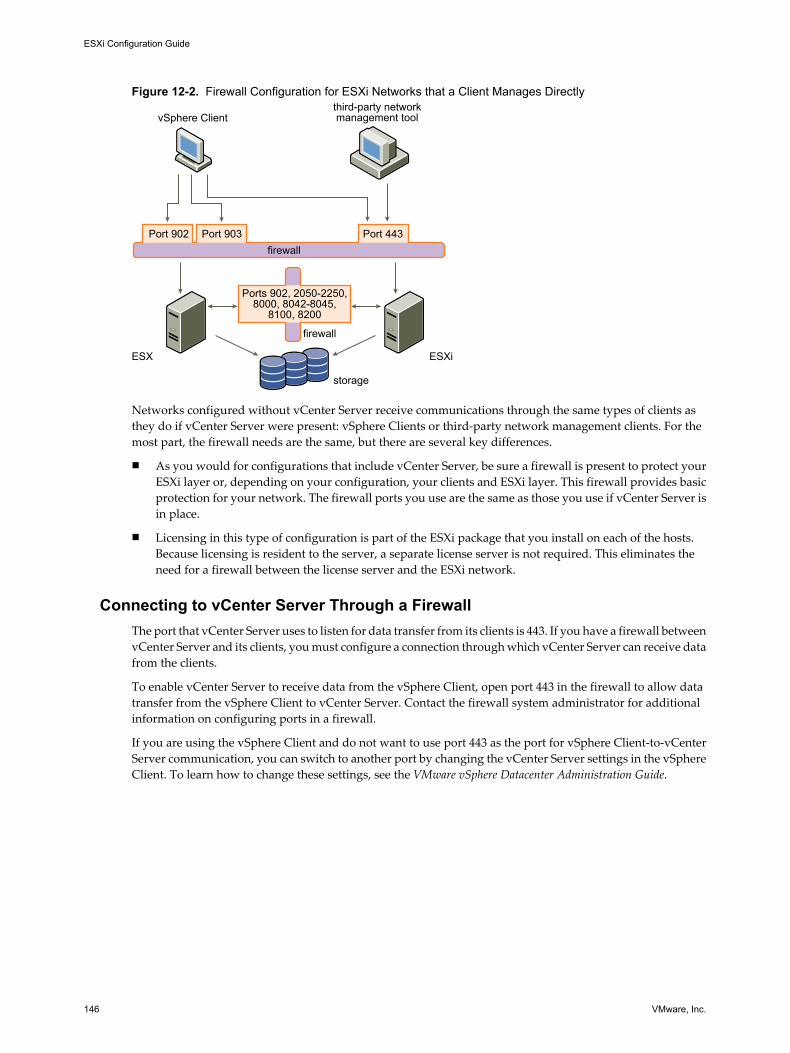
Figure 12-2. Firewall Configuration for ESXi Networks that a Client Manages Directly
ESX ESXi
vSphere Clientthird-party networkmanagement tool
storage
firewall
Ports 902, 2050-2250, 8000, 8042-8045,
8100, 8200
Port 902 Port 903 Port 443firewall
Networks configured without vCenter Server receive communications through the same types of clients asthey do if vCenter Server were present: vSphere Clients or third-party network management clients. For themost part, the firewall needs are the same, but there are several key differences.
n As you would for configurations that include vCenter Server, be sure a firewall is present to protect yourESXi layer or, depending on your configuration, your clients and ESXi layer. This firewall provides basicprotection for your network. The firewall ports you use are the same as those you use if vCenter Server isin place.
n Licensing in this type of configuration is part of the ESXi package that you install on each of the hosts.Because licensing is resident to the server, a separate license server is not required. This eliminates theneed for a firewall between the license server and the ESXi network.
Connecting to vCenter Server Through a FirewallThe port that vCenter Server uses to listen for data transfer from its clients is 443. If you have a firewall betweenvCenter Server and its clients, you must configure a connection through which vCenter Server can receive datafrom the clients.
To enable vCenter Server to receive data from the vSphere Client, open port 443 in the firewall to allow datatransfer from the vSphere Client to vCenter Server. Contact the firewall system administrator for additionalinformation on configuring ports in a firewall.
If you are using the vSphere Client and do not want to use port 443 as the port for vSphere Client-to-vCenterServer communication, you can switch to another port by changing the vCenter Server settings in the vSphereClient. To learn how to change these settings, see the VMware vSphere Datacenter Administration Guide.
ESXi Configuration Guide
146 VMware, Inc.

Connecting to the Virtual Machine Console Through a FirewallWhether you connect your client to ESXi hosts through vCenter Server or use a direct connection to the host,certain ports are required for user and administrator communication with virtual machine consoles. Theseports support different client functions, interface with different layers on ESXi, and use different authenticationprotocols.
Port 902 This is the port that vCenter Server assumes is available for receiving data fromthe ESXi host. The vSphere Client uses this port to provide a connection forguest operating system mouse, keyboard, screen (MKS) activities on virtualmachines. It is through this port that users interact with the virtual machineguest operating systems and applications. Port 902 is the port that the vSphereClient assumes is available when interacting with virtual machines.
Port 902 connects vCenter Server to the host through the VMwareAuthorization Daemon (vmware-authd). This daemon multiplexes port 902 datato the appropriate recipient for processing. VMware does not supportconfiguring a different port for this connection.
Port 443 The vSphere Client and SDK use this port to send data to vCenter Servermanaged hosts. Also, the vSphere Client and SDK, when connected directly toan ESXi host, use this port to support any management functions related to theserver and its virtual machines. Port 443 is the port that clients assume isavailable when sending data to the ESXi host. VMware does not supportconfiguring a different port for these connections.
Port 443 connects clients to the ESXi host through the SDK. The vmware-hostdmultiplexes port 443 data to the appropriate recipient for processing.
Figure 12-3 shows the relationships between vSphere Client functions, ports, and ESXi processes.
Figure 12-3. Port Use for vSphere Client Communications with ESXi
ESXi
vSphere Client
Port 443
vmware-hostd vmware-authd
virtual machinemanagement functions
virtual machineconsole
Port 903firewall
If you have a firewall between your vCenter Server system and vCenter Server managed host, open ports 443and 903 in the firewall to allow data transfer to ESXi hosts from vCenter Server and ESXi hosts directly fromthe vSphere Client.
For additional information on configuring the ports, see the firewall system administrator.
Chapter 12 Securing an ESXi Configuration
VMware, Inc. 147

Connecting ESXi Hosts Through FirewallsIf you have a firewall between two ESXi hosts and you want to allow transactions between the hosts or usevCenter Server to perform any source or target activities, such as VMware High Availability (HA) traffic,migration, cloning, or vMotion, you must configure a connection through which the managed hosts can receivedata.
To configure a connection for receiving data, open ports in the following ranges:
n 902 (server-to-server migration and provisioning traffic)
n 2050–2250 (for HA traffic)
n 8000 (for vMotion)
n 8042–8045 (for HA traffic)
Refer to the firewall system administrator for additional information on configuring the ports.
Configuring Firewall Ports for Supported Services and Management AgentsYou must configure firewalls in your environment to accept commonly supported services.
Although ESXi has no firewall itself, you must configure any other firewalls in your environment to acceptservices.
The following services and agents are commonly present in a vSphere environment:
n NFS client (insecure service)
n NTP client
n iSCSI software client
n CIM HTTP server (insecure service)
n CIM HTTPS server
n Syslog client
NOTE This list can change so you might find that some services and agents are not mentioned in the list. Youmight be required to perform additional activities to configure and enable these services.
TCP and UDP Ports for Management AccessvCenter Server, ESXi hosts, and other network components are accessed using predetermined TCP and UDPports. If you manage network components from outside a firewall, you might be required to reconfigure thefirewall to allow access on the appropriate ports.
Table 12-1 lists TCP and UDP ports, and the purpose and the type of each.
Table 12-1. TCP and UDP Ports
Port Purpose Traffic Type
80 HTTP accessThe default non-secure TCP Web port typically used in conjunction with port 443as a front end for access to ESXi networks from the Web. Port 80 redirects trafficto an HTTPS landing page (port 443).WS-Management
Incoming TCP
123 NTP Client Outgoing UDP
427 The CIM client uses the Service Location Protocol, version 2 (SLPv2) to find CIMservers.
Incoming andoutgoing UDP
ESXi Configuration Guide
148 VMware, Inc.

Table 12-1. TCP and UDP Ports (Continued)
Port Purpose Traffic Type
443 HTTPS accessvCenter Server access to ESXi hostsDefault SSL Web portvSphere Client access to vCenter ServervSphere Client access to ESXi hostsWS-ManagementvSphere Client access to vSphere Update ManagervSphere Converter access to vCenter Server
Incoming TCP
902 Host access to other hosts for migration and provisioningAuthentication traffic for ESXi and remote console traffic (xinetd/vmware-authd)vSphere Client access to virtual machine consoles(UDP) Status update (heartbeat) connection from ESXi to vCenter Server
Incoming TCP,outgoing UDP
903 Remote console traffic generated by user access to virtual machines on a specificESXi host.
Incoming TCP
2049 Transactions from NFS storage devicesThis port is used on the VMkernel interface.
Incoming andoutgoing TCP
2050–2250 Traffic between ESXi hosts for VMware High Availability (HA) and EMCAutostart Manager
Outgoing TCP,incoming andoutgoing UDP
3260 Transactions to iSCSI storage devicesThis port is used on the VMkernel interface.
Outgoing TCP
5900-5964 RFB protocol, which is used by management tools such as VNC Incoming andoutgoing TCP
5989 CIM XML transactions over HTTPS Incoming andoutgoing TCP
8000 Requests from vMotion Incoming andoutgoing TCP
8042–8045 Traffic between ESXi hosts for HA and EMC Autostart Manager Outgoing TCP,incoming andoutgoing UDP
8100, 8200 Traffic between ESXi hosts for VMware Fault Tolerance Outgoing TCP,incoming andoutgoing UDP
In addition to the TCP and UDP ports, you can configure other ports depending on your needs. You can usevSphere Client to open ports for supported services such as NFS.
Securing Virtual Machines with VLANsThe network can be one of the most vulnerable parts of any system. Your virtual machine network requires asmuch protection as your physical network. You can add security to your virtual machine network in severalways.
If your virtual machine network is connected to a physical network, it can be subject to breaches to the samedegree that a network made up of physical machines is. Even if the virtual machine network is isolated fromany physical network, virtual machines in the network can be subject to attacks from other virtual machinesin the network. The requirements for securing virtual machines are often the same as those for physicalmachines.
Chapter 12 Securing an ESXi Configuration
VMware, Inc. 149

Virtual machines are isolated from each other. One virtual machine cannot read or write another virtualmachine’s memory, access its data, use its applications, and so forth. However, within the network, any virtualmachine or group of virtual machines can still be the target of unauthorized access from other virtual machinesand might require further protection by external means.
You can add this level of security in different ways.
n Adding firewall protection to your virtual network by installing and configuring host-based firewalls onsome or all of its virtual machines.
For efficiency, you can set up private virtual machine Ethernet networks or virtual networks. With virtualnetworks, you install a host-based firewall on a virtual machine at the head of the virtual network. Thisserves as a protective buffer between the physical network adapter and the remaining virtual machinesin the virtual network.
Installing a host-based firewall on virtual machines at the head of virtual networks is a good securitypractice. However, because host-based firewalls can slow performance, balance your security needsagainst performance before you decide to install host-based firewalls on virtual machines elsewhere inthe virtual network.
n Keeping different virtual machine zones within a host on different network segments. If you isolate virtualmachine zones on their own network segments, you minimize the risks of data leakage from one virtualmachine zone to the next. Segmentation prevents various threats, including Address Resolution Protocol(ARP) spoofing, in which an attacker manipulates the ARP table to remap MAC and IP addresses, therebygaining access to network traffic to and from a host. Attackers use ARP spoofing to generate denials ofservice, hijack the target system, and otherwise disrupt the virtual network.
Planning segmentation carefully lowers the chances of packet transmissions between virtual machinezones, which prevents sniffing attacks that require sending network traffic to the victim. Also, an attackercannot use an insecure service in one virtual machine zone to access other virtual machine zones in thehost. You can implement segmentation by using either of two approaches, each of which has differentbenefits.
n Use separate physical network adapters for virtual machine zones to ensure that the zones are isolated.Maintaining separate physical network adapters for virtual machine zones is probably the most securemethod and is less prone to misconfiguration after the initial segment creation.
n Set up virtual local area networks (VLANs) to help safeguard your network. Because VLANs providealmost all of the security benefits inherent in implementing physically separate networks without thehardware overhead, they offer a viable solution that can save you the cost of deploying andmaintaining additional devices, cabling, and so forth.
VLANs are an IEEE standard networking scheme with specific tagging methods that allow routing of packetsto only those ports that are part of the VLAN. When properly configured, VLANs provide a dependable meansfor you to protect a set of virtual machines from accidental or malicious intrusions.
VLANs let you segment a physical network so that two machines in the network are unable to transmit packetsback and forth unless they are part of the same VLAN. For example, accounting records and transactions areamong a company’s most sensitive internal information. In a company whose sales, shipping, and accountingemployees all use virtual machines in the same physical network, you might protect the virtual machines forthe accounting department by setting up VLANs as shown in Figure 12-4.
ESXi Configuration Guide
150 VMware, Inc.
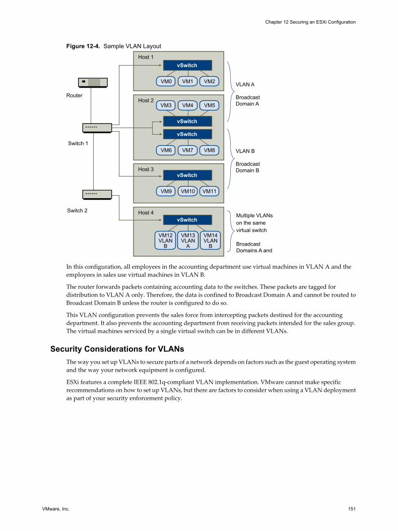
Figure 12-4. Sample VLAN Layout
VM3 VM4
vSwitch
VM5
vSwitch
VM6 VM7 VM8
vSwitch
VM0 VM1 VM2
vSwitch
VM9 VM10 VM11
VM12VLAN
B
VM13VLAN
A
VM14VLAN
B
vSwitch
Router
Host 1
Host 3
Host 4
Host 2
Switch 1
Switch 2Multiple VLANson the samevirtual switch
BroadcastDomains A and B
VLAN A
BroadcastDomain A
VLAN B
BroadcastDomain B
In this configuration, all employees in the accounting department use virtual machines in VLAN A and theemployees in sales use virtual machines in VLAN B.
The router forwards packets containing accounting data to the switches. These packets are tagged fordistribution to VLAN A only. Therefore, the data is confined to Broadcast Domain A and cannot be routed toBroadcast Domain B unless the router is configured to do so.
This VLAN configuration prevents the sales force from intercepting packets destined for the accountingdepartment. It also prevents the accounting department from receiving packets intended for the sales group.The virtual machines serviced by a single virtual switch can be in different VLANs.
Security Considerations for VLANsThe way you set up VLANs to secure parts of a network depends on factors such as the guest operating systemand the way your network equipment is configured.
ESXi features a complete IEEE 802.1q-compliant VLAN implementation. VMware cannot make specificrecommendations on how to set up VLANs, but there are factors to consider when using a VLAN deploymentas part of your security enforcement policy.
Chapter 12 Securing an ESXi Configuration
VMware, Inc. 151

VLANs as Part of a Broader Security ImplementationVLANs are an effective means of controlling where and how widely data is transmitted within the network.If an attacker gains access to the network, the attack is likely to be limited to the VLAN that served as the entrypoint, lessening the risk to the network as a whole.
VLANs provide protection only in that they control how data is routed and contained after it passes throughthe switches and enters the network. You can use VLANs to help secure Layer 2 of your network architecture—the data link layer. However, configuring VLANs does not protect the physical layer of your network modelor any of the other layers. Even if you create VLANs, provide additional protection by securing your hardware(routers, hubs, and so forth) and encrypting data transmissions.
VLANs are not a substitute for firewalls in your virtual machine configurations. Most network configurationsthat include VLANs also include firewalls. If you include VLANs in your virtual network, be sure that thefirewalls that you install are VLAN-aware.
Properly Configure VLANsEquipment misconfiguration and network hardware, firmware, or software defects can make a VLANsusceptible to VLAN-hopping attacks.
VLAN hopping occurs when an attacker with authorized access to one VLAN creates packets that trick physicalswitches into transmitting the packets to another VLAN that the attacker is not authorized to access.Vulnerability to this type of attack usually results from a switch being misconfigured for native VLANoperation, in which the switch can receive and transmit untagged packets.
To help prevent VLAN hopping, keep your equipment up to date by installing hardware and firmware updatesas they become available. Also, follow your vendor’s best practice guidelines when you configure yourequipment.
VMware virtual switches do not support the concept of a native VLAN. All data passed on these switches isappropriately tagged. However, because other switches in the network might be configured for native VLANoperation, VLANs configured with virtual switches can still be vulnerable to VLAN hopping.
If you plan to use VLANs to enforce network security, disable the native VLAN feature for all switches unlessyou have a compelling reason to operate some of your VLANs in native mode. If you must use native VLAN,see your switch vendor’s configuration guidelines for this feature.
Virtual Switch Protection and VLANsVMware virtual switches provide safeguards against certain threats to VLAN security. Because of the way thatvirtual switches are designed, they protect VLANs against a variety of attacks, many of which involve VLANhopping.
Having this protection does not guarantee that your virtual machine configuration is invulnerable to othertypes of attacks. For example, virtual switches do not protect the physical network against these attacks; theyprotect only the virtual network.
ESXi Configuration Guide
152 VMware, Inc.

Virtual switches and VLANs can protect against the following types of attacks.
MAC flooding Floods a switch with packets that contain MAC addresses tagged as havingcome from different sources. Many switches use a content-addressablememory (CAM) table to learn and store the source address for each packet.When the table is full, the switch can enter a fully open state in which everyincoming packet is broadcast on all ports, letting the attacker see all of theswitch’s traffic. This state might result in packet leakage across VLANs.
Although VMware virtual switches store a MAC address table, they do not getthe MAC addresses from observable traffic and are not vulnerable to this typeof attack.
802.1q and ISL taggingattacks
Force a switch to redirect frames from one VLAN to another by tricking theswitch into acting as a trunk and broadcasting the traffic to other VLANs.
VMware virtual switches do not perform the dynamic trunking required forthis type of attack and, therefore, are not vulnerable.
Double-encapsulationattacks
Occur when an attacker creates a double-encapsulated packet in which theVLAN identifier in the inner tag is different from the VLAN identifier in theouter tag. For backward compatibility, native VLANs strip the outer tag fromtransmitted packets unless configured to do otherwise. When a native VLANswitch strips the outer tag, only the inner tag is left, and that inner tag routesthe packet to a different VLAN than the one identified in the now-missing outertag.
VMware virtual switches drop any double-encapsulated frames that a virtualmachine attempts to send on a port configured for a specific VLAN. Therefore,they are not vulnerable to this type of attack.
Multicast brute-forceattacks
Involve sending large numbers of multicast frames to a known VLAN almostsimultaneously to overload the switch so that it mistakenly allows some of theframes to broadcast to other VLANs.
VMware virtual switches do not allow frames to leave their correct broadcastdomain (VLAN) and are not vulnerable to this type of attack.
Spanning-tree attacks Target Spanning-Tree Protocol (STP), which is used to control bridgingbetween parts of the LAN. The attacker sends Bridge Protocol Data Unit(BPDU) packets that attempt to change the network topology, establishingthemselves as the root bridge. As the root bridge, the attacker can sniff thecontents of transmitted frames.
VMware virtual switches do not support STP and are not vulnerable to thistype of attack.
Random frame attacks Involve sending large numbers of packets in which the source and destinationaddresses stay the same, but in which fields are randomly changed in length,type, or content. The goal of this attack is to force packets to be mistakenlyrerouted to a different VLAN.
VMware virtual switches are not vulnerable to this type of attack.
Because new security threats develop over time, do not consider this an exhaustive list of attacks. Regularlycheck VMware security resources on the Web to learn about security, recent security alerts, and VMwaresecurity tactics.
Chapter 12 Securing an ESXi Configuration
VMware, Inc. 153

Securing Virtual Switch PortsAs with physical network adapters, a virtual network adapter can send frames that appear to be from a differentmachine or impersonate another machine so that it can receive network frames intended for that machine.Also, like physical network adapters, a virtual network adapter can be configured so that it receives framestargeted for other machines.
When you create a virtual switch for your network, you add port groups to impose a policy configuration forthe virtual machines and storage systems attached to the switch. You create virtual ports through the vSphereClient.
As part of adding a port or port group to a virtual switch, the vSphere Client configures a security profile forthe port. You can use this security profile to ensure that ESXi prevents the guest operating systems for its virtualmachines from impersonating other machines on the network. This security feature is implemented so that theguest operating system responsible for the impersonation does not detect that the impersonation wasprevented.
The security profile determines how strongly you enforce protection against impersonation and interceptionattacks on virtual machines. To correctly use the settings in the security profile, you must understand the basicsof how virtual network adapters control transmissions and how attacks are staged at this level.
Each virtual network adapter has its own MAC address assigned when the adapter is created. This address iscalled the initial MAC address. Although the initial MAC address can be reconfigured from outside the guestoperating system, it cannot be changed by the guest operating system. In addition, each adapter has an effectiveMAC address that filters out incoming network traffic with a destination MAC address different from theeffective MAC address. The guest operating system is responsible for setting the effective MAC address andtypically matches the effective MAC address to the initial MAC address.
When sending packets, an operating system typically places its own network adapter’s effective MAC addressin the source MAC address field of the Ethernet frame. It also places the MAC address for the receiving networkadapter in the destination MAC address field. The receiving adapter accepts packets only when the destinationMAC address in the packet matches its own effective MAC address.
Upon creation, a network adapter’s effective MAC address and initial MAC address are the same. The virtualmachine’s operating system can alter the effective MAC address to another value at any time. If an operatingsystem changes the effective MAC address, its network adapter receives network traffic destined for the newMAC address. The operating system can send frames with an impersonated source MAC address at any time.This means an operating system can stage malicious attacks on the devices in a network by impersonating anetwork adapter that the receiving network authorizes.
You can use virtual switch security profiles on ESXi hosts to protect against this type of attack by setting threeoptions. If you change any default settings for a port, you must modify the security profile by editing virtualswitch settings in the vSphere Client.
MAC Address ChangesThe setting for the MAC Address Changes option affects traffic that a virtual machine receives.
When the option is set to Accept, ESXi accepts requests to change the effective MAC address to other than theinitial MAC address.
When the option is set to Reject, ESXi does not honor requests to change the effective MAC address to anythingother than the initial MAC address, which protects the host against MAC impersonation. The port that thevirtual adapter used to send the request is disabled and the virtual adapter does not receive any more framesuntil it changes the effective MAC address to match the initial MAC address. The guest operating system doesnot detect that the MAC address change was not honored.
NOTE The iSCSI initiator relies on being able to get MAC address changes from certain types of storage. If youare using ESXi iSCSI and have iSCSI storage, set the MAC Address Changes option to Accept.
ESXi Configuration Guide
154 VMware, Inc.

In some situations, you might have a legitimate need for more than one adapter to have the same MAC addresson a network—for example, if you are using Microsoft Network Load Balancing in unicast mode. WhenMicrosoft Network Load Balancing is used in the standard multicast mode, adapters do not share MACaddresses.
MAC address changes settings affect traffic leaving a virtual machine. MAC address changes will occur if thesender is permitted to make them, even if vSwitches or a receiving virtual machine does not permit MACaddress changes.
Forged TransmissionsThe setting for the Forged Transmits option affects traffic that is transmitted from a virtual machine.
When the option is set to Accept, ESXi does not compare source and effective MAC addresses.
To protect against MAC impersonation, you can set this option to Reject. If you do, the host compares thesource MAC address being transmitted by the operating system with the effective MAC address for its adapterto see if they match. If the addresses do not match, ESXi drops the packet.
The guest operating system does not detect that its virtual network adapter cannot send packets by using theimpersonated MAC address. The ESXi host intercepts any packets with impersonated addresses before theyare delivered, and the guest operating system might assume that the packets are dropped.
Promiscuous Mode OperationPromiscuous mode eliminates any reception filtering that the virtual network adapter would perform so thatthe guest operating system receives all traffic observed on the wire. By default, the virtual network adaptercannot operate in promiscuous mode.
Although promiscuous mode can be useful for tracking network activity, it is an insecure mode of operation,because any adapter in promiscuous mode has access to the packets regardless of whether some of the packetsare received only by a particular network adapter. This means that an administrator or root user within avirtual machine can potentially view traffic destined for other guest or host operating systems.
NOTE In some situations, you might have a legitimate reason to configure a virtual switch to operate inpromiscuous mode—for example, if you are running network intrusion detection software or a packet sniffer.
Internet Protocol SecurityInternet Protocol Security (IPsec) secures IP communications coming from and arriving at a host. ESXi hostssupport IPsec using IPv6.
When you set up IPsec on a host, you enable authentication and encryption of incoming and outgoing packets.When and how IP traffic is encrypted is depends on how you set up the system's security associations andsecurity policies
A security association determines how the system encrypts traffic. When you create a security association, youspecify the source and destination, encryption parameters, a name for the security association.
A security policy determines when the system should encrypt traffic. The security policy includes source anddestination information, the protocol and direction of traffic to be encrypted, the mode (transport or tunnel)and the security association to use.
Add a Security AssociationAdd a security association to specify encryption parameters for associated IP traffic.
You can add a security association using the vSphere CLI. For information on using the vSphere CLI, see thevSphere Command-Line Interface Installation and Scripting Guide and the vSphere Command-Line InterfaceReference.
Chapter 12 Securing an ESXi Configuration
VMware, Inc. 155

Procedure
1 Use the command vicfg-ipsec --add-sa.
2 Specify the source address using --sa-src source address.
3 Specify the destination address using --sa-dst destination address.
4 Choose the mode, either transport or tunnel, using --sa-mode mode.
5 Provide the security parameter index using --spi security parameter index.
The security parameter index identifies the security association to the host. It must be a hexadecimal witha 0x prefix. Each security association you create must have a unique combination of protocol and securityparameter index.
6 Choose the encryption algorithm using --ealgo encryption algorithm.
n 3des-cbc
n aes128-cbc
n null provides no encryption
7 Provide the encryption key using --ekey encryption key.
You can enter keys as ASCII text or as a hexadecimal with a 0x prefix.
8 Choose the authentication algorithm, hmac-sha1 or hmac-sha2-256, using --ialgo authenticationalgorithm.
9 Provide the authentication key using --ikey authentication key.
You can enter keys as ASCII text or as a hexadecimal with a 0x prefix.
10 Provide a name for the security association using name.
Example: Example New Security Association CommandThe following example contains extra line breaks for readability.
vicfg-ipsec --add-sa
--sa-src 3ffe:501:ffff:0::a
--sa-dst 3ffe:501:ffff:0001:0000:0000:0000:0001
--sa-mode transport
--spi 0x1000
--ealgo 3des-cbc
--ekey 0x6970763672656164796c6f676f336465736362636f757432
--ialgo hmac-sha1
--ikey 0x6970763672656164796c6f67736861316f757432
sa1
Remove a Security AssociationYou can remove a security association from the ESXi host.
You can remove a security association using the vSphere CLI. For information on using the vSphere CLI, seethe vSphere Command-Line Interface Installation and Scripting Guide and the vSphere Command-Line InterfaceReference.
Prerequisites
Be sure that the security association you want to use is not currently in use. If you try to remove a securityassociation that is in use, the removal operation fails.
ESXi Configuration Guide
156 VMware, Inc.
Procedure
u Use the command vicfg-ipsec --remove-sa security association name.
List Available Security AssociationsESXi can provide a list of all security associations available for use by security policies. The list includes bothuser created security associations and any security associations the VMkernel installed using Internet KeyExchange.
You can get a list of available security associations using the vSphere CLI. For information on using the vSphereCLI, see the vSphere Command-Line Interface Installation and Scripting Guide and the vSphere Command-LineInterface Reference.
Procedure
u Use the command vicfg-ipsec -l.
ESXi displays a list of all available security associations.
Create a Security PolicyCreate a security policy to determine when to use the authentication and encryption parameters set in a securityassociation.
You can add a security policy using the vSphere CLI. For information on using the vSphere CLI, see the vSphereCommand-Line Interface Installation and Scripting Guide and the vSphere Command-Line Interface Reference.
Prerequisites
Before creating a security policy, add a security association with the appropriate authentication and encryptionparameters.
Procedure
1 Use the command vicfg-ipsec --add-sp.
2 Specify the source IP address and prefix length using --sp-src source address.
3 Specify the destination address and prefix length using --sp-dst destination address.
4 Specify the source port using --src-port port.
The source port must be a number between 0 and 65535.
5 Specify the destination port using --dst-port port.
The destination port must be a number between 0 and 65535.
6 Choose the upper layer protocol using --ulproto protocol.
n tcp
n udp
n icmp6
n any
7 Choose the direction, in or out, in which you want to monitor traffic using --dir direction.
Chapter 12 Securing an ESXi Configuration
VMware, Inc. 157

8 Specify the action to take when traffic with the specified parameters is encountered using --actionaction.
Option Description
none Take no action.
discard Do not allow data in or out.
ipsec Use the authentication and encryption information supplied in the securityassociation to determine whether the data comes from a trusted source.
9 Choose the mode, either tunnel or transport, using --sp-mode mode.
10 Specify the security association for this security policy to use using --sa-name security associationname.
11 Specify the name of the security policy by using name.
Example: Example New Security Policy CommandThe following example includes extra line breaks for readability.
vicfg-ipsec --add-sp
--sp-src 2001:db8:1::/64
--sp-dst 2002:db8:1::/64
--src-port 23
--dst-port 25
--ulproto tcp
--dir out
--action ipsec
--sp-mode transport
--sa-name sa1
sp1
Remove a Security PolicyYou can remove a security policy from the ESXi host.
You can remove a security policy using the vSphere CLI. For information on using the vSphere CLI, see thevSphere Command-Line Interface Installation and Scripting Guide and the vSphere Command-Line InterfaceReference.
Prerequisites
Be sure that the security policy you want to use is not currently in use. If you try to remove a security policythat is in use, the removal operation fails.
Procedure
u Use the command vicfg-ipsec --remove-sp security policy name.
List Available Security PoliciesESXi can provide a list of all security policies on the host.
You can get a list of available security policies using the vSphere CLI. For information on using the vSphereCLI, see the vSphere Command-Line Interface Installation and Scripting Guide and the vSphere Command-LineInterface Reference.
Procedure
u Use the command vicfg-ipsec -L.
ESXi Configuration Guide
158 VMware, Inc.

ESXi displays a list of all available security policies.
Securing iSCSI StorageThe storage you configure for an ESXi host might include one or more storage area networks (SANs) that useiSCSI. When you configure iSCSI on an ESXi host, you can take several measures to minimize security risks.
iSCSI is a means of accessing SCSI devices and exchanging data records by using TCP/IP over a network portrather than through a direct connection to a SCSI device. In iSCSI transactions, blocks of raw SCSI data areencapsulated in iSCSI records and transmitted to the requesting device or user.
iSCSI SANs let you make efficient use of existing Ethernet infrastructures to provide ESXi hosts access to storageresources that they can dynamically share. iSCSI SANs provide an economical storage solution forenvironments that rely on a common storage pool to serve numerous users. As with any networked system,your iSCSI SANs can be subject to security breaches.
NOTE The requirements and procedures for securing an iSCSI SAN are similar for the hardware iSCSI adaptersyou can use with ESXi hosts and for iSCSI configured directly through the ESXi host.
Securing iSCSI Devices Through AuthenticationOne means of securing iSCSI devices from unwanted intrusion is to require that the ESXi host, or initiator, beauthenticated by the iSCSI device, or target, whenever the host attempts to access data on the target LUN.
The goal of authentication is to prove that the initiator has the right to access a target, a right granted whenyou configure authentication.
ESXi does not support Kerberos, Secure Remote Protocol (SRP), or public-key authentication methods for iSCSI.Additionally, it does not support IPsec authentication and encryption.
Use the vSphere Client to determine whether authentication is being performed and to configure theauthentication method.
Enabling Challenge Handshake Authentication Protocol (CHAP) for iSCSI SANsYou can configure the iSCSI SAN to use CHAP authentication.
In CHAP authentication, when the initiator contacts an iSCSI target, the target sends a predefined ID valueand a random value, or key, to the initiator. The initiator creates a one-way hash value that it sends to thetarget. The hash contains three elements: a predefined ID value, the random value that the target sends, anda private value, or CHAP secret, that the initiator and target share. When the target receives the hash from theinitiator, it creates its own hash value by using the same elements and compares it to the initiator’s hash. If theresults match, the target authenticates the initiator.
ESXi supports unidirectional and bidirectional CHAP authentication for iSCSI. In unidirectional CHAPauthentication, the target authenticates the initiator, but the initiator does not authenticate the target. Inbidirectional CHAP authentication, an additional level of security enables the initiator to authenticate thetarget.
ESXi supports CHAP authentication at the adapter level, when only one set of authentication credentials canbe sent from the host to all targets. It also supports per-target CHAP authentication, which enables you toconfigure different credentials for each target to achieve greater target refinement.
See “Configuring CHAP Parameters for iSCSI Adapters,” on page 94 for information about how to work withCHAP.
Chapter 12 Securing an ESXi Configuration
VMware, Inc. 159

Disabling iSCSI SAN AuthenticationYou can configure the iSCSI SAN to use no authentication. Communications between the initiator and targetare still authenticated in a rudimentary way because the iSCSI target devices are typically set up tocommunicate with specific initiators only.
Choosing not to enforce more stringent authentication can make sense if your iSCSI storage is housed in onelocation and you create a dedicated network or VLAN to service all your iSCSI devices. The iSCSI configurationis secure because it is isolated from any unwanted access, much as a Fibre Channel SAN is.
As a basic rule, disable authentication only if you are willing to risk an attack to the iSCSI SAN or cope withproblems that result from human error.
See “Configuring CHAP Parameters for iSCSI Adapters,” on page 94 for information about how to work withCHAP.
Protecting an iSCSI SANWhen you plan your iSCSI configuration, take measures to improve the overall security of the iSCSI SAN. YouriSCSI configuration is only as secure as your IP network, so by enforcing good security standards when youset up your network, you help safeguard your iSCSI storage.
The following are some specific suggestions for enforcing good security standards.
Protect Transmitted DataA primary security risk in iSCSI SANs is that an attacker might sniff transmitted storage data.
Take additional measures to prevent attackers from easily seeing iSCSI data. Neither the hardware iSCSIadapter nor the ESXi host iSCSI initiator encrypts the data that they transmit to and from the targets, makingthe data more vulnerable to sniffing attacks.
Allowing your virtual machines to share virtual switches and VLANs with your iSCSI configuration potentiallyexposes iSCSI traffic to misuse by a virtual machine attacker. To help ensure that intruders cannot listen toiSCSI transmissions, make sure that none of your virtual machines can see the iSCSI storage network.
If you use a hardware iSCSI adapter, you can accomplish this by making sure that the iSCSI adapter andESXi physical network adapter are not inadvertently connected outside the host by virtue of sharing a switchor some other means. If you configure iSCSI directly through the ESXi host, you can accomplish this byconfiguring iSCSI storage through a different virtual switch than the one used by your virtual machines, asshown in Figure 12-5.
ESXi Configuration Guide
160 VMware, Inc.

Figure 12-5. iSCSI Storage on a Separate Virtual Switch
In addition to protecting the iSCSI SAN by giving it a dedicated virtual switch, you can configure your iSCSISAN on its own VLAN to improve performance and security. Placing your iSCSI configuration on a separateVLAN ensures that no devices other than the iSCSI adapter have visibility into transmissions within the iSCSISAN. Also, network congestion from other sources cannot interfere with iSCSI traffic.
Secure iSCSI PortsWhen you run iSCSI devices, the ESXi host does not open any ports that listen for network connections. Thismeasure reduces the chances that an intruder can break into the ESXi host through spare ports and gain controlover the host. Therefore, running iSCSI does not present any additional security risks at the ESXi host end ofthe connection.
Any iSCSI target device that you run must have one or more open TCP ports to listen for iSCSI connections.If any security vulnerabilities exist in the iSCSI device software, your data can be at risk through no fault ofESXi. To lower this risk, install all security patches that your storage equipment manufacturer provides andlimit the devices connected to the iSCSI network.
Chapter 12 Securing an ESXi Configuration
VMware, Inc. 161

ESXi Configuration Guide
162 VMware, Inc.

Authentication and User Management 13ESXi handles user authentication and supports user and group permissions. In addition, you can encryptconnections to the vSphere Client and SDK.
This chapter includes the following topics:
n “Securing ESXi Through Authentication and Permissions,” on page 163
n “About Users, Groups, Permissions, and Roles,” on page 164
n “Working with Users and Groups on ESXi Hosts,” on page 168
n “Encryption and Security Certificates for ESXi,” on page 173
Securing ESXi Through Authentication and PermissionsWhen a vSphere Client or vCenter Server user connects to a ESXi host, a connection is established with theVMware Host Agent process. The process uses the user names and passwords for authentication.
ESXi authenticates users accessing ESXi hosts using the vSphere Client or SDK. The default installation of ESXiuses a local password database for authentication.
Figure 13-1 shows a basic example of how ESXi authenticates transactions from the vSphere Client.
NOTE CIM transactions also use ticket-based authentication in connecting with the vmware-hostd process.
Figure 13-1. Authentication for vSphere Client Communications with ESXi
ESXi
vSphere Client
vmware-hostd
management functions
console
user name/passwordauthentication
ESXi authentication transactions with third-party network management clients are also direct interactions withthe vmware-hostd process.
VMware, Inc. 163
To make sure that authentication works efficiently for your site, perform basic tasks such as setting up users,groups, permissions, and roles, configuring user attributes, adding your own certificates, and determiningwhether you want to use SSL.
About Users, Groups, Permissions, and RolesvCenter Server and ESXi hosts use a combination of user name, password, and permissions to authenticate auser for access and authorize activities. You can control access to hosts, clusters, datastores, resource pools,networking port groups, and virtual machines by assigning permissions.
Access to an ESXi host and its resources is granted when a known user with appropriate permissions logs into the host with a correct password. vCenter Server uses a similar approach when determining whether togrant access to a user.
vCenter Server and ESXi hosts deny access under the following circumstances:
n A user not in the user list attempts to log in.
n A user enters the wrong password.
n A user is in the list but was not assigned permissions.
n A user who successfully logged in attempts operations that they do not have permission to perform.
As part of managing ESXi hosts and vCenter Server, you must plan how to handle particular types of usersand permissions. ESXi and vCenter Server use sets of privileges, or roles, to control which operations individualusers or groups can perform. Predefined roles are provided, but you can also create new ones. You can manageusers more easily by assigning them to groups. When you apply a role to the group, all users in the groupinherit the role.
The topics in this section apply to local users and groups. You can also use Active Directory to manage usersand groups for ESXi.
Understanding UsersA user is an individual authorized to log in to either an ESXi host or vCenter Server.
ESXi users fall into two categories: those who can access the host through vCenter Server and those who canaccess by directly logging in to the host from the vSphere Client, a third-party client, or a command shell.
Authorized vCenterServer users
Authorized users for vCenter Server are those included in the Windowsdomain list that vCenter Server references or are local Windows users on thevCenter Server host.
You cannot use vCenter Server to manually create, remove, or otherwisechange users. You must use the tools for managing your Windows domain.Any changes you make are reflected in vCenter Server. However, the userinterface does not provide a user list for you to review.
Direct-access users Users authorized to work directly on an ESXi host are those added to theinternal user list by a system administrator.
An administrator can perform a variety of management activities for theseusers, such as changing passwords, group memberships, and permissions aswell as adding and removing users.
The user list that ESXi maintains locally is separate from the users known to vCenter Server, which are eitherlocal Windows users or users that are part of the Windows domain. Even if the lists appear to have commonusers (for instance, a user called devuser), treat these users separately. If you log in to vCenter Server as devuser,you might have permission to view and delete files from a datastore, whereas if you log in to an ESXi host asdevuser, you might not. If Active Directory authentication has been configured on the host, then the sameWindows domain users known to vCenter Server will be available on the ESXi host.
ESXi Configuration Guide
164 VMware, Inc.

Because of the confusion that duplicate naming can cause, check the vCenter Server user list before you createESXi host users to avoid duplicating names. To check for vCenter Server users, review the Windows domainlist.
Understanding GroupsA group is a set of users that share a common set of rules and permissions. When you assign permissions to agroup, all users in the group inherit them, and you do not have to work with the user profiles individually.
As an administrator, decide how to structure groups to achieve your security and usage goals. For example,three part-time sales team members work different days, and you want them to share a single virtual machinebut not use the virtual machines belonging to sales managers. In this case, you might create a group calledSalesShare that includes the three sales people and give the group permission to interact with only one object,the shared virtual machine. They cannot perform any actions on the sales managers’ virtual machines.
The group lists in vCenter Server and an ESXi host are drawn from the same sources as their respective userlists. The group lists in vCenter Server are drawn from the local users or any trusted domain, and the grouplists for an ESXi host are drawn from the local user list or from any trusted Windows domain.
Understanding Password RequirementsBy default, ESXi enforces requirements for user passwords.
When you create a password, include a mix of characters from four character classes: lowercase letters,uppercase letters, numbers, and special characters such as an underscore or dash.
Your user password must meet the following length requirements.
n Passwords containing characters from one or two character classes must be at least eight characters long.
n Passwords containing characters from three character classes must be at least seven characters long.
n Passwords containing characters from all four character classes must be at least six characters long.
NOTE An uppercase character that begins a password does not count toward the number of character classesused. A number that ends a password does not count toward the number of character classes used.
You can also use a passphrase, which is a phrase consisting of at least three words, each of which is 8 to 40characters long.
Example: Sample PasswordsThe following password candidates meet the requirements of ESXi.
n xQaTEhbU: Contains eight characters from two character classes.
n xQaT3pb: Contains seven characters from three character classes.
n xQaT3#: Contains six characters from four character classes.
The following password candidates do not meet the requirements of ESXi.
n Xqat3hb: Begins with an uppercase character, reducing the effective number of character classes to two.Eight characters are required when you use only two character classes.
n xQaTEh2: Ends with a number, reducing the effective number of character classes to two. Eight charactersare required when you use only two character classes.
Chapter 13 Authentication and User Management
VMware, Inc. 165

Understanding PermissionsFor ESXi and vCenter Server, permissions are defined as access roles that consist of a user and the user’sassigned role for an object such as a virtual machine or ESXi host.
Most vCenter Server and ESXi users have limited ability to manipulate the objects associated with the host.Users with the Administrator role have full access rights and permissions on all virtual objects such asdatastores, hosts, virtual machines, and resource pools. By default, the Administrator role is granted to theroot user. If vCenter Server manages the host, vpxuser is also an Administrator user.
The list of privileges is the same for both ESXi and vCenter Server, and you use the same method to configurepermissions.
You can create roles and set permissions through a direct connection to the ESXi host. Because these tasks arewidely performed in vCenter Server, see the VMware vSphere Datacenter Administration Guide for informationon working with permissions and roles.
Assigning root User PermissionsRoot users can only perform activities on the specific ESXi host that they are logged in to.
For security reasons, you might not want to use the root user in the Administrator role. In this case, you canchange permissions after installation so that the root user no longer has administrative privileges or you candelete the root user’s access permissions altogether through the vSphere Client as described in the VMwarevSphere Datacenter Administration Guide. If you do so, you must first create another permission at the root levelthat has a different user assigned to the Administrator role.
Assigning the Administrator role to a different user helps you maintain security through traceability. ThevSphere Client logs all actions that the Administrator role user initiates as events, providing you with an audittrail. If all administrators log in as the root user, you cannot tell which administrator performed an action. Ifyou create multiple permissions at the root level—each associated with a different user or user group—youcan track the actions of each administrator or administrative group.
After you create an alternative Administrator user, you can assign a different role to the root user. To managethe host using vCenter server, the new user you created must have full Administrator privileges on the host.
NOTE vicfg commands do not perform an access check. Therefore, even if you limit the root user’s privileges,it does not affect what that user can do using the command-line interface commands.
Understanding vpxuser PermissionsThe vpxuser permission is used for vCenter Server when managing activities for the host. The vpxuser iscreated when an ESXi host is attached to vCenter Server.
vCenter Server has Administrator privileges on the host that it manages. For example, vCenter Server canmove virtual machines to and from hosts and perform configuration changes needed to support virtualmachines.
The vCenter Server administrator can perform most of the same tasks on the host as the root user and alsoschedule tasks, work with templates, and so forth. However, the vCenter Server administrator cannot directlycreate, delete, or edit users and groups for ESXi hosts. These tasks can only be performed by a user withAdministrator permissions directly on each ESXi host.
NOTE You cannot manage the vpxuser using Active Directory.
CAUTION Do not change vpxuser in any way and do not change its permissions. If you do so, you mightexperience problems in working with ESXi hosts through vCenter Server.
ESXi Configuration Guide
166 VMware, Inc.

Assigning dcui User PermissionsThe dcui user runs on hosts and acts with Administrator rights. This user’s primary purpose is to configurehosts for lockdown mode from the direct console.
This user acts as an agent for the direct console and must not be modified or used by interactive users.
CAUTION Do not change the dcui user in any way and do not change its permissions. If you do so, you mightexperience problems in working with the ESXi host through the local user interface.
Understanding RolesvCenter Server and ESXi grant access to objects only to users who are assigned permissions for the object.When you assign a user or group permissions for the object, you do so by pairing the user or group with a role.A role is a predefined set of privileges.
ESXi hosts provide three default roles, and you cannot change the privileges associated with these roles. Eachsubsequent default role includes the privileges of the previous role. For example, the Administrator roleinherits the privileges of the Read Only role. Roles you create yourself do not inherit privileges from any ofthe default roles.
You can create roles and set permissions through a direct connection to the ESXi host. Because most userscreate roles and set permissions in vCenter Server, see the VMware vSphere Datacenter Administration Guide forinformation on working with permissions and roles.
Assigning the No Access RoleUsers assigned the No Access role for an object cannot view or change the object in any way. New users andgroups are assigned this role by default. You can change the role on an object-by-object basis.
The root user and vpxuser permissions are the only users not assigned the No Access role by default. Instead,they are assigned the Administrator role. You can delete the root user’s permissions altogether or change itsrole to No Access as long as you first create a replacement permission at the root level with the Administratorrole and associate this role with a different user.
Assigning the Read Only RoleUsers assigned the Read Only role for an object are allowed to view the state of the object and details aboutthe object.
With this role, a user can view virtual machine, host, and resource pool attributes. The user cannot view theremote console for a host. All actions through the menus and toolbars are disallowed.
Assigning the Administrator RoleUsers assigned the Administrator role for an object are allowed to view and perform all actions on the object.This role also includes all permissions inherent in the Read Only role.
If you are acting in the Administrator role on an ESXi host, you can grant permissions to individual users andgroups on that host. If you are acting in the Administrator role in vCenter Server, you can grant permissionsto any user or group included in the Windows domain list that vCenter Server references.
vCenter Server registers any selected Windows domain user or group through the process of assigningpermissions. By default, all users who are members of the local Windows Administrators group on vCenterServer are granted the same access rights as any user assigned to the Administrator role. Users who aremembers of the Administrators group can log in as individuals and have full access.
Users who are in the Active Directory group ESX Admins are automatically assigned the Administrator role.
Chapter 13 Authentication and User Management
VMware, Inc. 167

For security reasons, consider removing the Windows Administrators group from the Administrator role. Youcan change permissions after installation. Alternately, you can use the vSphere Client to delete the WindowsAdministrators group access permissions, but you must first create another permission at the root level thathas a different user assigned to the Administrator role.
Direct Console User Interface AccessOnly users that are assigned the Administrator role can log in to the direct console. To allow access to the directconsole, add the user to the local administrators group.
Procedure
1 Log in to the host using the vSphere Client.
2 Click the Users & Groups tab and click Users.
3 Right-click the user and click Edit to open the Edit User dialog box.
4 From the Group drop-down menu, select localadmin and click Add.
5 Click OK.
Working with Users and Groups on ESXi HostsIf you are directly connected to an ESXi host through the vSphere Client, you can create, edit, and delete usersand groups. These users and groups are visible in the vSphere Client whenever you log in to the ESXi host,but are not available if you log in to vCenter Server.
The topics in this section apply to local users and groups. You can also use Active Directory to manage usersand groups for ESXi.
View, Sort, and Export a List of Users and GroupsYou can view, sort, and export lists of ESXi users and groups to a file that is in HTML, XML, Microsoft Excel,or CSV format.
Procedure
1 Log in to the host using the vSphere Client.
2 Click the Users & Groups tab and click Users or Groups.
3 Determine how to sort the table, and hide or show columns according to the information you want to seein the exported file.
n To sort the table by any of the columns, click the column heading.
n To show or hide columns, right-click any of the column headings and select or deselect the name ofthe column to hide.
n To show or hide columns, right-click any of the column headings and select or deselect the name ofthe column to hide.
4 Right-click anywhere in the table and click Export List to open the Save As dialog box.
5 Select a path and enter a filename.
6 Select the file type and click OK.
ESXi Configuration Guide
168 VMware, Inc.

Add a User to the Users TableAdding a user to the users table updates the internal user list that ESXi maintains.
Prerequisites
Review the password requirements described in “Understanding Password Requirements,” on page 165.
Procedure
1 Log in to the host using the vSphere Client.
2 Click the Users & Groups tab and click Users.
3 Right-click anywhere in the Users table and click Add to open the Add New User dialog box.
4 Enter a login, a user name, a numeric user ID (UID), and a password.
n Specifying the user name and UID are optional. If you do not specify the UID, the vSphere Clientassigns the next available UID.
n Create a password that meets the length and complexity requirements. The host checks for passwordcompliance using the default authentication plug-in, pam_passwdqc.so. If the password is notcompliant, the following error appears: A general system error occurred: passwd: Authenticationtoken manipulation error.
n If you switched to the pam_cracklib.so authentication plug-in, password compliance is not enforced.
5 To add the user to a group, select the group name from the Group drop-down menu and click Add.
6 Click OK.
Modify the Settings for a UserYou can change the user ID, user name, password, and group settings for a user. You can also grant a usershell access.
Prerequisites
Review the password requirements as described in “Understanding Password Requirements,” on page 165.
Procedure
1 Log in to the host using the vSphere Client.
2 Click the Users & Groups tab and click Users.
3 Right-click the user and click Edit to open the Edit User dialog box.
4 To change the user ID, enter a numeric user UID in the UID text box.
The vSphere Client assigns the UID when you first create the user. In most cases, you do not have to changethis assignment.
5 Enter a new user name.
6 To change the user’s password, select Change Password and enter the new password.
n Create a password that meets the length and complexity requirements. The host checks for passwordcompliance using the default authentication plug-in, pam_passwdqc.so. If the password is notcompliant, the following error appears: A general system error occurred: passwd: Authenticationtoken manipulation error.
n If you switched to the pam_cracklib.so authentication plug-in, password compliance is not enforced.
7 To add the user to a group, select the group name from the Group drop-down menu and click Add.
Chapter 13 Authentication and User Management
VMware, Inc. 169

8 To remove the user from a group, select the group name from the Group membership box and clickRemove.
9 Click OK.
Remove a User or GroupYou can remove a user or group from the ESXi host.
CAUTION Do not remove the root user.
If you remove a user from the host, they lose permissions to all objects on the host and cannot log in again.
NOTE Users who are logged in and are removed from the domain keep their host permissions until you restartthe host.
Removing a group does not affect the permissions granted individually to the users in that group orpermissions granted as part of inclusion in another group.
Procedure
1 Log in to the host using the vSphere Client.
2 Click the Users & Groups tab and click Users or Groups.
3 Right-click the user or group to remove and select Remove.
Add a Group to the Groups TableAdding a group to the ESXi groups table updates the internal group list maintained by the host.
Procedure
1 Log in to the host using the vSphere Client.
2 Click the Users & Groups tab and click Groups.
3 Right-click anywhere in the Groups table and click Add to open the Create New Group dialog box.
4 Enter a group name and numeric group ID (GID) in the Group ID text box.
Specifying the GID is optional. If you do not specify a GID, the vSphere Client assigns the next availablegroup ID.
5 For each user that you want to add as a group member, select the user name from the list and click Add.
6 Click OK.
Add or Remove Users from a GroupYou can add or remove a user from a group in the groups table.
Procedure
1 Log in to the host using the vSphere Client.
2 Click the Users & Groups tab and click Groups.
3 Right-click the group to modify and select Properties to open the Edit Group dialog box.
4 To add the user to a group, select the group name from the Group drop-down menu and click Add.
5 To remove the user from a group, select the group name from the Group membership box and clickRemove.
ESXi Configuration Guide
170 VMware, Inc.

6 Click OK.
Configure a Host to Use a Directory ServiceYou can configure the ESXi host to use a directory service such as Active Directory to manage users and groups.
Prerequisites
n Verify that you have set up an Active Directory domain. Refer to your directory server documentation.
n Ensure that the host name of ESXi is fully qualified with the domain name of the Active Directory forest.
fully qualified domain name = host_name.domain_name
Procedure
1 Synchronize the time between ESXi and the directory service system using NTP.
ESXi supports synchronizing time with an external NTPv3 or NTPv4 server that is compliant with RFC5905 and RFC 1305. The Microsoft Windows W32Time service does not meet these requirements.
2 Ensure that the DNS servers you configured for the host can resolve the host names for the Active Directorycontrollers.
You can use the vSphere Client DNS and Routing Configuration dialog box to modify host name and DNSserver information for the host.
a In the vSphere Client, select the host in the inventory.
b Click the Configuration tab and click DNS and Routing.recount
c Click the Properties link at the top right of the panel to access the DNS and Routing Configurationdialog box.
What to do next
Join a directory service domain using the vSphere Client.
Add a Host to a Directory Service DomainTo use a directory service, you must join the host to the directory service domain.
You can enter the domain name in one of two ways:
n name.tld (for example, domain.com): The account is created under the default container.
n name.tld/container/path (for example, domain.com/OU1/OU2): The account is created under a particularorganizational unit (OU).
Prerequisites
Verify that the vSphere Client is connected to a vCenter Server system or to the host.
Procedure
1 Select a host in the vSphere Client inventory, and click the Configuration tab.
2 Under Software, select Authentication Services and click Properties.
Chapter 13 Authentication and User Management
VMware, Inc. 171

3 In the Directory Services Configuration dialog box, select the type of authentication from the drop-downmenu.
Option Description
If you select Active Directory Enter a domain in the form of name.tld or name.tld/container/pathand click Join Domain.
If the host is already using adirectory service
Select Leave Domain to leave the domain and join another.
4 Enter the user name and password of an Active Directory user who has permissions to join the host to the
domain, and click OK.
5 Click OK to close the Directory Services Configuration dialog box.
Use Host Profiles to Apply Permissions to HostsWhen you join a host to an Active Directory domain, you must define roles on the host for a user or group inthat domain. Otherwise, the host is not accessible to Active Directory users or groups. You can use host profilesto set a required role for a user or group and to apply the change to one or more hosts.
Prerequisites
You must have an existing host profile. See “Creating a Host Profile,” on page 196.
Verify that the hosts to which you apply a profile are in maintenance mode.
Procedure
1 Using the vSphere Client, select View > Management > Host Profiles.
2 Right-click an existing host profile and select Edit Profile.
3 Expand the profile tree, and then expand Security configuration.
4 Right-click the Permission rules folder and select Add Profile.
5 Expand Permission rules and select Permission.
6 On the Configuration Details tab in the right pane, click the Configure a permission drop-down menuand select Require a Permission Rule.
7 Enter the name of a user and group.
Use the format DOMAIN\name, where DOMAIN is the name of the Active Directory domain and name is the username or group name.
8 (Optional) If the name you entered is a group (not a single user), select the Name refers to a group ofusers check box.
9 Enter the assigned role name for the user or group (usually Admin).
The role name is case-sensitive. If this is a system role, you must use the nonlocalized role name. Forexample, for the Administrator role, enter Admin. For the Read-only role, enter ReadOnly.
10 Select the Propagate permission check box and click OK.
What to do next
1 Attach the profile to the hosts as described in “Attach Entities from the Host,” on page 200.
2 Apply the profile to the hosts as described in “Apply a Profile from the Host,” on page 201.
ESXi Configuration Guide
172 VMware, Inc.

Encryption and Security Certificates for ESXiESXi supports SSL v3 and TLS v1, generally referred to here as SSL. If SSL is enabled, data is private, protected,and cannot be modified in transit without detection.
All network traffic is encrypted as long as you did not change the Web proxy service to allow unencryptedtraffic for the port.
Host certificate checking is enabled by default and SSL certificates are used to encrypt network traffic.However, ESXi uses automatically generated certificates that are created as part of the installation process andstored on the host. These certificates are unique and make it possible to begin using the server, but they arenot verifiable and are not signed by a trusted-well-known certificate authority (CA). These default certificatesare vulnerable to possible man-in-the-middle attacks.
To receive the full benefit of certificate checking, particularly if you intend to use encrypted remote connectionsexternally, install new certificates that are signed by a valid internal certificate authority or purchase a certificatefrom a trusted security authority.
NOTE If the self-signed certificate is used, clients receive a warning about the certificate. To address this issue,install a certificate that is signed by a recognized certificate authority. If CA-signed certificates are not installed,all communication between vCenter Server and vSphere Clients is encrypted using a self-signed certificate.These certificates do not provide the authentication security you might need in a production environment.
Enable Certificate Checking and Verify Host ThumbprintsTo prevent man-in-the-middle attacks and to fully use the security that certificates provide, certificate checkingis enabled by default. You can verify that certificate checking is enabled in the vSphere Client.
NOTE vCenter Server certificates are preserved across upgrades.
Procedure
1 Log in to a vCenter Server system using the vSphere Client.
2 Select Administration > vCenter Server Settings.
3 Click SSL Settings in the left pane and verify that Check host certificates is selected.
4 If there are hosts that require manual validation, compare the thumbprints listed for the hosts to thethumbprints in the host console.
To obtain the host thumbprint for ESXi, use the direct console.
a Log in to the direct console and press F2 to access the System Customization menu.
b Select View Support Information.
The host thumbprint appears in the column on the right.
5 If the thumbprint matches, select the Verify check box next to the host.
Hosts that are not selected will be disconnected after you click OK.
6 Click OK.
Chapter 13 Authentication and User Management
VMware, Inc. 173

Generate New Certificates for the ESXi HostThe ESXi host generates certificates the first time the system is started. Under certain circumstances, you mightbe required to force the host to generate new certificates. You typically generate new certificates only if youchange the host name or accidentally delete the certificate.
Procedure
1 Select Reset Customized Settings in the direct console.
2 Reboot the system to regenerate the certificates.
Replace a Default Certificate with a CA-Signed CertificateThe ESXi host uses automatically generated certificates that are created as part of the installation process. Thesecertificates are unique and make it possible to begin using the server, but they are not verifiable and they arenot signed by a trusted, well-known certificate authority (CA).
Using default certificates might not comply with the security policy of your organization. If you require acertificate from a trusted certificate authority, you can replace the default certificate.
NOTE If the host has Verify Certificates enabled, replacing the default certificate might cause vCenter Serverto stop managing the host. If the new certificate is not verifiable by vCenter Server, you must reconnect thehost using the vSphere Client.
ESXi supports only X.509 certificates to encrypt session information sent over SSL connections between serverand client components.
Prerequisites
All file transfers and other communications occur over a secure HTTPS session. The user used to authenticatethe session must have the privilege Host.Config.AdvancedConfig on the host. For more information on ESXiprivileges, see “About Users, Groups, Permissions, and Roles,” on page 164.
Procedure
1 Put the host into Maintenance Mode.
2 Use the vifs command to put a copy of the certificate and key files on the ESXi host.
The form this command takes for the certificate and key respectively is:
vifs --server <hostname> --username <username> --put rui.crt /host/ssl_cert
vifs --server <hostname> --username <username> --put rui.key /host/ssl_key
3 Use the Restart Management Agents operation through the direct console to have the settings take effect.
4 Exit Maintenance Mode.
Upload a Certificate and Key Using a HTTPS PUTIn addition to the vifs command, you can use third-party applications to upload certificates. Applications thatsupport HTTPS PUT operations work with the HTTPS interface that is included with ESXi. For example, youcan use SeaMonkey Composer to upload a certificate and key.
Procedure
1 Put the host into Maintenance Mode.
2 In your upload application, open the file.
ESXi Configuration Guide
174 VMware, Inc.

3 Publish the file to one of these locations.
n For certificates, https://hostname/host/ssl_crt.
n For keys, https://hostname/host/sslkey.
4 In the direct console, use the Restart Management Agents operation to have the settings take effect.
5 Exit Maintenance Mode.
Configure SSL TimeoutsYou can configure SSL timeouts for ESXi.
Timeout periods can be set for two types of idle connections:
n The Read Timeout setting applies to connections that have completed the SSL handshake process withport 443 of ESXi.
n The Handshake Timeout setting applies to connections that have not completed the SSL handshakeprocess with port 443 of ESXi.
Both connection timeouts are set in milliseconds.
Idle connections are disconnected after the timeout period. By default, fully established SSL connections havea timeout of infinity.
Procedure
1 Use the vifs command to get a copy of the config.xml file to edit.
For Linux systems, use this command.
vifs --server hostname --username username --get /host/hostAgentConfig.xml
directory/hostAgentConfig.xml
For Windows systems, use this command.
vifs --server hostname --username username --get /host/hostAgentConfig.xml
directory\hostAgentConfig.xml
2 Use a text editor to open the config.xml file.
3 Enter the <readTimeoutMs> value in milliseconds.
For example, to set the Read Timeout to 20 seconds, enter the following command.
<readTimeoutMs>20000</readTimeoutMs>
4 Enter the <handshakeTimeoutMs> value in milliseconds.
For example, to set the Handshake Timeout to 20 seconds, enter the following command.
<handshakeTimeoutMs>20000</handshakeTimeoutMs>
5 Save your changes and close the file.
6 Use the vifs command to put a copy of the config.xml file on the ESXi host.
For Linux systems, use this command.
vifs --server hostname --username username --put
directory/hostAgentConfig.xml /host/hostAgentConfig.xml
For Windows systems, use this command.
vifs --server hostname --username username --put
directory\hostAgentConfig.xml /host/hostAgentConfig.xml
Chapter 13 Authentication and User Management
VMware, Inc. 175

7 Use the Restart Management Agents operation through the direct console to have the settings take effect.
Example: Configuration FileThe following section from the file /etc/vmware/hostd/config.xml shows where to enter the SSL timeoutsettings.
<vmacore>
...
<http>
<readTimeoutMs>20000</readTimeoutMs>
</http>
...
<ssl>
...
<handshakeTimeoutMs>20000</handshakeTimeoutMs>
...
</ssl>
</vmacore>
Modifying ESXi Web Proxy SettingsWhen you modify Web proxy settings, you have several encryption and user security guidelines to consider.
NOTE Use the Restart Management Agents operation through the direct console to restart the vmware-hostdprocess after making any changes to host directories or authentication mechanisms.
n Do not set up certificates using pass phrases. ESXi does not support pass phrases, also known as encryptedkeys. If you set up a pass phrase, ESXi processes cannot start correctly.
n You can configure the Web proxy so that it searches for certificates in a location other than the defaultlocation. This capability proves useful for companies that prefer to centralize their certificates on a singlemachine so that multiple hosts can use the certificates.
CAUTION If certificates are not stored locally on the host—for example, if they are stored on an NFS share—the host cannot access those certificates if ESXi loses network connectivity. As a result, a client connectingto the host cannot successfully participate in a secure SSL handshake with the host.
n To support encryption for user names, passwords, and packets, SSL is enabled by default for vSphere Webservices SDK connections. If you want to configure the these connections so that they do not encrypttransmissions, disable SSL for your vSphere Web Services SDK connection by switching the connectionfrom HTTPS to HTTP.
Consider disabling SSL only if you created a fully trusted environment for these clients, where firewallsare in place and transmissions to and from the host are fully isolated. Disabling SSL can improveperformance, because you avoid the overhead required to perform encryption.
n To protect against misuse of ESXi services, most internal ESXi services are accessible only through port443, the port used for HTTPS transmission. Port 443 acts as a reverse proxy for ESXi. You can see a list ofservices on ESXi through an HTTP welcome page, but you cannot directly access the Storage Adaptersservices without proper authorization.
You can change this configuration so that individual services are directly accessible through HTTPconnections. Do not make this change unless you are using ESXi in a fully trusted environment.
n When you upgrade vCenter Server, the certificate remains in place.
ESXi Configuration Guide
176 VMware, Inc.
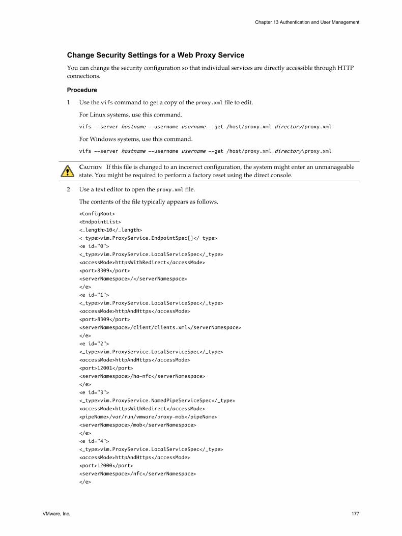
Change Security Settings for a Web Proxy ServiceYou can change the security configuration so that individual services are directly accessible through HTTPconnections.
Procedure
1 Use the vifs command to get a copy of the proxy.xml file to edit.
For Linux systems, use this command.
vifs --server hostname --username username --get /host/proxy.xml directory/proxy.xml
For Windows systems, use this command.
vifs --server hostname --username username --get /host/proxy.xml directory\proxy.xml
CAUTION If this file is changed to an incorrect configuration, the system might enter an unmanageablestate. You might be required to perform a factory reset using the direct console.
2 Use a text editor to open the proxy.xml file.
The contents of the file typically appears as follows.
<ConfigRoot>
<EndpointList>
<_length>10</_length>
<_type>vim.ProxyService.EndpointSpec[]</_type>
<e id="0">
<_type>vim.ProxyService.LocalServiceSpec</_type>
<accessMode>httpsWithRedirect</accessMode>
<port>8309</port>
<serverNamespace>/</serverNamespace>
</e>
<e id="1">
<_type>vim.ProxyService.LocalServiceSpec</_type>
<accessMode>httpAndHttps</accessMode>
<port>8309</port>
<serverNamespace>/client/clients.xml</serverNamespace>
</e>
<e id="2">
<_type>vim.ProxyService.LocalServiceSpec</_type>
<accessMode>httpAndHttps</accessMode>
<port>12001</port>
<serverNamespace>/ha-nfc</serverNamespace>
</e>
<e id="3">
<_type>vim.ProxyService.NamedPipeServiceSpec</_type>
<accessMode>httpsWithRedirect</accessMode>
<pipeName>/var/run/vmware/proxy-mob</pipeName>
<serverNamespace>/mob</serverNamespace>
</e>
<e id="4">
<_type>vim.ProxyService.LocalServiceSpec</_type>
<accessMode>httpAndHttps</accessMode>
<port>12000</port>
<serverNamespace>/nfc</serverNamespace>
</e>
Chapter 13 Authentication and User Management
VMware, Inc. 177

<e id="5">
<_type>vim.ProxyService.LocalServiceSpec</_type>
<accessMode>httpsWithRedirect</accessMode>
<port>8307</port>
<serverNamespace>/sdk</serverNamespace>
</e>
<e id="6">
<_type>vim.ProxyService.NamedPipeTunnelSpec</_type>
<accessMode>httpOnly</accessMode>
<pipeName>/var/run/vmware/proxy-sdk-tunnel</pipeName>
<serverNamespace>/sdkTunnel</serverNamespace>
</e>
<e id="7">
<_type>vim.ProxyService.LocalServiceSpec</_type>
<accessMode>httpsWithRedirect</accessMode>
<port>8308</port>
<serverNamespace>/ui</serverNamespace>
</e>
<e id="8">
<_type>vim.ProxyService.LocalServiceSpec</_type>
<accessMode>httpsOnly</accessMode>
<port>8089</port>
<serverNamespace>/vpxa</serverNamespace>
</e>
<e id="9">
<_type>vim.ProxyService.LocalServiceSpec</_type>
<accessMode>httpsWithRedirect</accessMode>
<port>8889</port>
<serverNamespace>/wsman</serverNamespace>
</e>
</EndpointList>
</ConfigRoot>
3 Change the security settings as required.
For example, you might want to modify entries for services that use HTTPS to add the option of HTTPaccess.
n e id is an ID number for the server ID XML tag. ID numbers must be unique within the HTTP area.
n _type is the name of the service you are moving.
n accessmode is the forms of communication the service permits. Acceptable values include:
n httpOnly – The service is accessible only over plain-text HTTP connections.
n httpsOnly – The service is accessible only over HTTPS connections.
n httpsWithRedirect – The service is accessible only over HTTPS connections. Requests over HTTPare redirected to the appropriate HTTPS URL.
n httpAndHttps – The service is accessible both over HTTP and HTTPS connections.
n port is the port number assigned to the service. You can assign a different port number to the service.
n serverNamespace is the namespace for the server that provides this service, for example /sdk or /mob.
4 Save your changes and close the file.
ESXi Configuration Guide
178 VMware, Inc.

5 Use the vifs command to put a copy of the proxy.xml file on the ESXi host.
For Linux, use this command.
vifs --server hostname --username username --put directory/proxy.xml /host/proxy.xml
For Windows, use this command.
vifs --server hostname --username username --put directory\proxy.xml /host/proxy.xml
6 Use the Restart Management Agents operation through the direct console to have the settings take effect.
Chapter 13 Authentication and User Management
VMware, Inc. 179

ESXi Configuration Guide
180 VMware, Inc.

Security Best Practices and Scenarios 14A series of ESXi deployment scenarios can help you understand how best to employ the security features inyour own deployment. Scenarios also illustrate some basic security recommendations that you can considerwhen creating and configuring virtual machines.
This chapter includes the following topics:n “Security Approaches for Common ESXi Deployments,” on page 181
n “ESXi Lockdown Mode,” on page 184
n “Virtual Machine Recommendations,” on page 187
Security Approaches for Common ESXi DeploymentsYou can compare security approaches for different types of deployments to help plan security for your ownESXi deployment.
The complexity of ESXi deployments can vary significantly depending on the size of your company, the waythat data and resources are shared with the outside world, whether there are multiple datacenters or only one,and so forth. Inherent in the following deployments are policies for user access, resource sharing, and securitylevel.
Single-Customer DeploymentIn a single-customer deployment, ESXi hosts are owned and maintained within a single corporation and singledatacenter. Host resources are not shared with outside users. One site administrator maintains the hosts, whichare run on a number of virtual machines.
The single-customer deployment does not allow customer administrators, and the site administrator is solelyresponsible for maintaining the various virtual machines. The corporation staffs a set of system administratorswho do not have accounts on the host and cannot access any of the ESXi tools such as vCenter Server orcommand line shells for the host. These system administrators have access to virtual machines through thevirtual machine console so that they can load software and perform other maintenance tasks inside the virtualmachines.
Table 14-1 shows how you might handle sharing for the components that you use and configure for the host.
VMware, Inc. 181

Table 14-1. Sharing for Components in a Single-Customer Deployment
Function Configuration Comments
Virtual machines share the samephysical network?
Yes Configure your virtual machines on the same physicalnetwork.
VMFS sharing? Yes All .vmdk files reside in the same VMFS partition.
Virtual machine memoryovercommitment?
Yes Configure the total memory for the virtual machines asgreater than the total physical memory.
Table 14-2 shows how you might set up user accounts for the host.
Table 14-2. User Account Setup in a Single-Customer Deployment
User Category Total Number of Accounts
Site administrators 1
Customer administrators 0
System administrators 0
Business users 0
Table 14-3 shows the level of access for each user.
Table 14-3. User Access in a Single-Customer Deployment
Access Level Site Administrator System Administrator
Root access? Yes No
Virtual machine creation and modification? Yes No
Virtual machine access through the console? Yes Yes
Multiple-Customer Restricted DeploymentIn a multiple-customer restricted deployment, ESXi hosts are in the same datacenter and are used to serveapplications for multiple customers. The site administrator maintains the hosts, and these hosts run a numberof virtual machines dedicated to the customers. Virtual machines that belong to the various customers can beon the same host, but the site administrator restricts resource sharing to prevent rogue interaction.
Although there is only one site administrator, several customer administrators maintain the virtual machinesassigned to their customers. This deployment also includes customer system administrators who do not haveESXi accounts but have access to the virtual machines through the virtual machine console so that they canload software and perform other maintenance tasks inside the virtual machines.
Table 14-4 shows how you might handle sharing for the components you use and configure for the host.
Table 14-4. Sharing for Components in a Multiple-Customer Restricted Deployment
Function Configuration Comments
Virtual machines share the samephysical network?
Partial Put the virtual machines for each customer on a differentphysical network. All physical networks are independent ofeach other.
VMFS sharing? No Each customer has its own VMFS partition, and the virtualmachine .vmdk files reside exclusively on that partition. Thepartition can span multiple LUNs.
Virtual machine memoryovercommitment?
Yes Configure the total memory for the virtual machines as greaterthan the total physical memory.
Table 14-5 shows how you might set up user accounts for the ESXi host.
ESXi Configuration Guide
182 VMware, Inc.

Table 14-5. User Account Setup in a Multiple-Customer Restricted Deployment
User Category Total Number of Accounts
Site administrators 1
Customer administrators 10
System administrators 0
Business users 0
Table 14-6 shows the level of access for each user.
Table 14-6. User Access in a Multiple-Customer Restricted Deployment
Access Level Site AdministratorCustomerAdministrator
SystemAdministrator
Root access? Yes No No
Virtual machine creation and modification? Yes Yes No
Virtual machine access through the console? Yes Yes Yes
Multiple-Customer Open DeploymentIn a multiple-customer open deployment, ESXi hosts are in the same datacenter and are used to serveapplications for multiple customers. The site administrator maintains the hosts, and these hosts run a numberof virtual machines dedicated to the customers. Virtual machines that belong to the various customers can beon the same host, but there are fewer restrictions on resource sharing.
Although there is only one site administrator in a multiple-customer open deployment, several customeradministrators maintain the virtual machines assigned to their customers. The deployment also includescustomer system administrators who do not have ESXi accounts but have access to the virtual machinesthrough the virtual machine console so that they can load software and perform other maintenance tasks insidethe virtual machines. Lastly, a group of business users who do not have accounts can use virtual machines torun their applications.
Table 14-7 shows how you might handle sharing for the components that you use and configure for the host.
Table 14-7. Sharing for Components in a Multiple-Customer Open Deployment
Function Configuration Comments
Virtual machines share the samephysical network?
Yes Configure your virtual machines on the same physicalnetwork.
VMFS sharing? Yes Virtual machines can share VMFS partitions, and theirvirtual machine .vmdk files can reside on shared partitions.Virtual machines do not share .vmdk files.
Virtual machine memoryovercommitment?
Yes Configure the total memory for the virtual machines asgreater than the total physical memory.
Table 14-8 shows how you might set up user accounts for the host.
Table 14-8. User Account Setup in a Multiple-Customer Open Deployment
User Category Total Number of Accounts
Site administrators 1
Customer administrators 10
System administrators 0
Business users 0
Chapter 14 Security Best Practices and Scenarios
VMware, Inc. 183

Table 14-9 shows the level of access for each user.
Table 14-9. User Access in a Multiple-Customer Open Deployment
Access Level Site AdministratorCustomerAdministrator
SystemAdministrator Business User
Root access? Yes No No No
Virtual machine creation andmodification?
Yes Yes No No
ESXi Lockdown ModeTo increase the security of your ESXi hosts, you can put them in lockdown mode.
When you enable lockdown mode, no users other than vpxuser have authentication permissions, nor can theyperform operations against the host directly. Lockdown mode forces all operations to be performed throughvCenter Server.
When a host is in lockdown mode, you cannot run vCLI commands from an administration server, from ascript, or from vMA against the host. External software or management tools might not be able to retrieve ormodify information from the ESXi host.
NOTE The root user is still authorized to log in to the direct console user interface when lockdown mode isenabled.
Enabling or disabling lockdown mode affects which types of users are authorized to access host services, butit does not affect the availability of those services. In other words, if Local Tech Support Mode, Remote TechSupport Mode (SSH), or the Direct Console User Interface (DCUI) services are enabled, they will continue torun whether or not the host is in lockdown mode.
You can enable lockdown mode using the Add Host wizard to add an ESXi host to vCenter Server, using thevSphere Client to manage a host, or using the direct console user interface.
NOTE If you enable or disable lockdown mode using the direct console user interface, permissions for usersand groups on the host are discarded. To preserve these permissions, you must enable and disable lockdownmode using the vSphere Client connected to vCenter Server.
Lockdown mode is only available on ESXi hosts that have been added to vCenter Server.
Lockdown Mode BehaviorEnabling lockdown mode affects which users are authorized to access host services.
Table 14-10 lists which services can be used by different types of users when the host is running in lockdownmode, compared to when the host is running in normal mode.
Table 14-10. Lockdown Mode Behavior
Service Normal Mode Lockdown Mode
vSphere WebServices API All users, based on ESXi permissions vCenter only (vpxuser)
CIM Providers Root users and Admin users vCenter only (ticket)
Direct Console User Interface (DCUI) Root users and Admin users Root users
Local Tech Support Mode (TSM) Root users and Admin users No users
Remote Tech Support Mode (SSH) Root users and Admin users No users
ESXi Configuration Guide
184 VMware, Inc.

Enable Lockdown Mode Using the vSphere ClientEnable lockdown mode to require that all configuration changes go through vCenter Server. You can alsoenable or disable lockdown mode through the direct console.
Procedure
1 Log in to a vCenter Server system using the vSphere Client.
2 Select the host in the inventory panel.
3 Click the Configuration tab and click Security Profile.
4 Click the Edit link next to lockdown mode.
The Lockdown Mode dialog box appears.
5 Select Enable Lockdown Mode.
6 Click OK.
Enable Lockdown Mode from the Direct Console User InterfaceYou can enable lockdown mode from the direct console user interface.
NOTE If you enable or disable lockdown mode using the direct console user interface, permissions for usersand groups on the host are discarded. To preserve these permissions, you must enable and disable lockdownmode using the vSphere Client connected to vCenter Server.
Procedure
u Toggle the Configure Lockdown Mode setting.
Using Troubleshooting ServicesTroubleshooting services are disabled by default on ESXi. You can enable these services if necessary.
Troubleshooting services can be enabled and disabled whether or not the host is running in lockdown mode.
Local Tech SupportMode (TSM)
You can enable this service to troubleshoot issues locally.
Remote Tech SupportMode Service (SSH)
You can enable this service to troubleshoot issues remotely.
Direct Console UserInterface Service (DCUI)
When you enable this service while running in lockdown mode, you can login locally to the direct console user interface as the root user and disablelockdown mode. You can then troubleshoot the issue using a direct connectionto the vSphere Client or by enabling Tech Support Mode.
The root user and users with the Administrator role can access troubleshooting services. Users who are in theActive Directory group ESX Admins are automatically assigned the Administrator role.
NOTE Do not enable troubleshooting services until they are required. When troubleshooting services areenabled, anyone who is logged in has complete control of the host.
Chapter 14 Security Best Practices and Scenarios
VMware, Inc. 185

Lockdown Mode ConfigurationsYou can enable or disable troubleshooting services to create different lockdown mode configurations.
Table 14-11 lists which troubleshooting services are enabled for three typical configurations.
CAUTION If you lose access to vCenter Server while running in Total Lockdown Mode, you must reinstall ESXito gain access to the host.
Table 14-11. Lockdown Mode Configurations
Service Default ConfigurationRecommendedConfiguration
Total LockdownConfiguration
Lockdown Off On On
Local Tech Support Mode(TSM)
Off Off Off
Remote Tech Support Mode(SSH)
Off Off Off
Direct Console User Interface(DCUI)
On On Off
Configure Troubleshooting Services with the vSphere ClientUse the vSphere Client to enable troubleshooting services.
Procedure
1 Log in to a vCenter Server system using the vSphere Client.
2 Select the host in the inventory panel.
3 Click the Configuration tab and click Security Profile.
4 Select a service from the list.
n Local Tech Support
n Remote Tech Support (SSH)
n Direct Console UI
5 Click Options and select Start and stop manually.
6 Select Start to enable the service.
7 Click OK.
8 (Optional) Set the timeout for Tech Support Mode.
By default, the timeout for Tech Support Mode is 0 (disabled).
The timeout setting is the number of minutes that can elapse before you must log in after Tech SupportMode is enabled. After the timeout period, if you have not logged in, Tech Support Mode is disabled.
NOTE If you are logged in when the timeout period elapses, your session will persist. However, TechSupport Mode will be disabled, preventing other users from logging in.
a Select the host in the inventory and click the Configuration tab.
b Under Software, select Advanced Settings.
c In the UserVars.TSMTimeOut field, enter the timeout setting.
ESXi Configuration Guide
186 VMware, Inc.

9 Click OK.
Configure Troubleshooting Services with the Direct Console User InterfaceUse the direct console user interface to enable troubleshooting services.
Procedure
1 From the direct console user interface, press F2 to access the System Customization menu.
2 Select Troubleshooting Options and press Enter.
3 From the Troubleshooting Mode Options menu, select a troubleshooting service to enable or disable.
n Local Tech Support Mode
n Remote Tech Support Mode (SSH)
4 Press Enter to enable or disable the service.
5 (Optional) Set the timeout for Tech Support Mode.
By default, the timeout for Tech Support Mode is 0 (disabled).
The timeout setting is the number of minutes that can elapse before you must log in after Tech SupportMode is enabled. After the timeout period, if you have not logged in, Tech Support Mode is disabled.
NOTE If you are logged in when the timeout period elapses, your session will persist. However, TechSupport Mode will be disabled, preventing other users from logging in.
a From the Troubleshooting Mode Options menu, select Modify Tech Support timeout and pressEnter.
b Enter the timeout in minutes.
c Press Enter.
Virtual Machine RecommendationsThere are several safety precautions to consider when evaluating virtual machine security and administeringvirtual machines.
Installing Antivirus SoftwareBecause each virtual machine hosts a standard operating system, consider protecting it from viruses byinstalling antivirus software. Depending on how you are using the virtual machine, you might also want toinstall a software firewall.
Stagger the schedule for virus scans, particularly in deployments with a large number of virtual machines.Performance of systems in your environment will degrade significantly if you scan all virtual machinessimultaneously.
Because software firewalls and antivirus software can be virtualization-intensive, you can balance the needfor these two security measures against virtual machine performance, especially if you are confident that yourvirtual machines are in a fully trusted environment.
Chapter 14 Security Best Practices and Scenarios
VMware, Inc. 187

Limiting Exposure of Sensitive Data Copied to the ClipboardCopy and paste operations are disabled by default for ESXi to prevent exposing sensitive data that has beencopied to the clipboard.
When copy and paste is enabled on a virtual machine running VMware Tools, you can copy and paste betweenthe guest operating system and remote console. As soon as the console window gains focus, non-privilegedusers and processes running in the virtual machine can access the clipboard for the virtual machine console.If a user copies sensitive information to the clipboard before using the console, the user—perhaps unknowingly—exposes sensitive data to the virtual machine. To prevent this problem, copy and paste operations for theguest operating system are disabled by default.
It is possible to enable copy and paste operations for virtual machines if necessary.
Enable Copy and Paste Operations Between the Guest Operating System andRemote ConsoleTo copy and paste between the guest operating system and remote console, you must enable copy and pasteoperations using the vSphere Client.
Procedure
1 Log into a vCenter Server system using the vSphere Client and select the virtual machine.
2 On the Summary tab, click Edit Settings.
3 Select Options > Advanced > General and click Configuration Parameters.
4 Click Add Row and type the following values in the Name and Value columns.
Name Value
isolation.tools.copy.disable false
isolation.tools.paste.disable false
NOTE These options override any settings made in the guest operating system’s VMware Tools controlpanel.
5 Click OK to close the Configuration Parameters dialog box, and click OK again to close the Virtual MachineProperties dialog box.
6 Restart the virtual machine.
Removing Unnecessary Hardware DevicesUsers and processes without privileges on a virtual machine can connect or disconnect hardware devices, suchas network adapters and CD-ROM drives. Therefore, removing unnecessary hardware devices can helpprevent attacks.
Attackers can use this capability to breach virtual machine security in several ways. For example, an attackerwith access to a virtual machine can connect a disconnected CD-ROM drive and access sensitive informationon the media left in the drive, or disconnect a network adapter to isolate the virtual machine from its network,resulting in a denial of service.
As a general security precaution, use commands on the vSphere Client Configuration tab to remove anyunneeded or unused hardware devices. Although this measure tightens virtual machine security, it is not agood solution in situations where you might bring an unused device back into service at a later time.
ESXi Configuration Guide
188 VMware, Inc.

Prevent a Virtual Machine User or Process from Disconnecting DevicesIf you do not want to permanently remove a device, you can prevent a virtual machine user or process fromconnecting or disconnecting the device from within the guest operating system.
Procedure
1 Log in to a vCenter Server system using the vSphere Client.
2 Select the virtual machine in the inventory panel.
3 On the Summary tab, click Edit Settings.
4 Select Options > General Options and make a record of the path displayed in the Virtual MachineConfiguration File text box.
5 Use the vifs command to get a copy of the virtual machine configuration files from the location you notedin Step 4.
Virtual machine configuration files are located in the /vmfs/volumes/datastore directory, wheredatastore is the name of the storage device on which the virtual machine files reside. For example, if thevirtual machine configuration file you obtained from the Virtual Machine Properties dialog box is[vol1]vm-finance/vm-finance.vmx, use this command.
vifs --server hostname --username username --get /vmfs/volumes/vol1/vm-finance/vm-finance.vmx
directory/vm-finance.vmx
6 Use a text editor to add the following line to the .vmx file, where device_name is the name of the device youwant to protect (for example, ethernet1).
device_name.allowGuestConnectionControl = "false"
NOTE By default, Ethernet 0 is configured to disallow device disconnection. The only reason you mightchange this is if a prior administrator set device_name.allowGuestConnectionControl to true.
7 Save your changes and close the file.
8 Use vifs to put your modified copy of the file at the location you noted in Step 4.
vifs --server hostname --username username --put directory/vm-
finance.vmx /vmfs/volumes/vol1/vm-finance/vm-finance.vmx
9 In the vSphere Client, right-click the virtual machine and select Power Off.
10 Right-click the virtual machine and select Power On.
Limiting Guest Operating System Writes to Host MemoryThe guest operating system processes send informational messages to the ESXi host through VMware Tools.If the amount of data the host stored as a result of these messages was unlimited, an unrestricted data flowwould provide an opportunity for an attacker to stage a denial-of-service (DoS) attack.
The informational messages sent by guest operating processes are known as setinfo messages and typicallycontain name-value pairs that define virtual machine characteristics or identifiers that the host stores—forexample, ipaddress=10.17.87.224. The configuration file containing these name-value pairs is limited to a sizeof 1MB, which prevents attackers from staging a DoS attack by writing software that mimics VMware Toolsand filling the host's memory with arbitrary configuration data, which consumes space needed by the virtualmachines.
If you require more than 1MB of storage for name-value pairs, you can change the value as required. You canalso prevent the guest operating system processes from writing any name-value pairs to the configuration file.
Chapter 14 Security Best Practices and Scenarios
VMware, Inc. 189

Modify Guest Operating System Variable Memory LimitYou can increase the guest operating system variable memory limit if large amounts of custom informationare being stored in the configuration file.
Procedure
1 Log in to a vCenter Server system using the vSphere Client.
2 Select the virtual machine in the inventory panel.
3 On the Summary tab, click Edit Settings.
4 Select Options > Advanced > General and click Configuration Parameters.
5 If the size limit attribute is not present, you must add it.
a Click Add Row.
b In the Name column, type tools.setInfo.sizeLimit.
c In the Value column, type Number of Bytes.
If the size limit attribute exists, modify it to reflect the appropriate limits.
6 Click OK to close the Configuration Parameters dialog box, and click OK again to close the Virtual MachineProperties dialog box.
Prevent the Guest Operating System Processes from Sending ConfigurationMessages to the HostYou can prevent guests from writing any name-value pairs to the configuration file. This is appropriate whenguest operating systems must be prevented from modifying configuration settings.
Procedure
1 Log in to a vCenter Server system using the vSphere Client.
2 Select the virtual machine in the inventory panel.
3 On the Summary tab, click Edit Settings.
4 Select Options > Advanced > General and click Configuration Parameters.
5 Click Add Row and type the following values in the Name and Value columns.
n In the Name column: isolation.tools.setinfo.disable
n In the Value column: true
6 Click OK to close the Configuration Parameters dialog box, and click OK again to close the Virtual MachineProperties dialog box.
ESXi Configuration Guide
190 VMware, Inc.

Configuring Logging Levels for the Guest Operating SystemVirtual machines can write troubleshooting information into a virtual machine log file stored on the VMFSvolume. Virtual machine users and processes can abuse logging either on purpose or inadvertently so thatlarge amounts of data flood the log file. Over time, the log file can consume enough file system space to causea denial of service.
To prevent this problem, consider modifying logging settings for virtual machine guest operating systems.These settings can limit the total size and number of log files. Normally, a new log file is created each time youreboot a host, so the file can grow to be quite large. You can ensure new log file creation happens morefrequently by limiting the maximum size of the log files. VMware recommends saving 10 log files, each onelimited to 100KB. These values are large enough to capture sufficient information to debug most problems thatmight occur.
Each time an entry is written to the log, the size of the log is checked. If it is over the limit, the next entry iswritten to a new log. If the maximum number of log files exists, the oldest log file is deleted. A DoS attack thatavoids these limits could be attempted by writing an enormous log entry, but each log entry is limited in sizeto 4KB, so no log files are ever more than 4KB larger than the configured limit.
Limit Log File Numbers and SizesTo prevent virtual machine users and processes from flooding the log file, which can lead to denial of service,you can limit the number and size of the log files ESXi generates.
Procedure
1 Log in to a vCenter Server system using the vSphere Client.
2 On the Summary tab, click Edit Settings.
3 Select Options > General Options and make a record of the path displayed in the Virtual MachineConfiguration File text box.
4 Use the vifs command to get a copy of the virtual machine configuration files from the location you notedin Step 3.
Virtual machine configuration files are located in the /vmfs/volumes/datastore directory, wheredatastore is the name of the storage device on which the virtual machine files reside. For example, if thevirtual machine configuration file you obtained from the Virtual Machine Properties dialog box is[vol1]vm-finance/vm-finance.vmx, use this command.
vifs --server hostname --username username --get /vmfs/volumes/vol1/vm-finance/vm-finance.vmx
directory/vm-finance.vmx
5 To limit the log size, use a text editor to add or edit the following line to the .vmx file, wheremaximum_size is the maximum file size in bytes.
log.rotateSize=maximum_size
For example, to limit the size to around 100KB, enter 100000.
6 To keep a limited number of log files, use a text editor to add or edit the following line to the .vmx file,where number_of_files_to_keep is the number of files the server keeps.
log.keepOld=number_of_files_to_keep
For example, to keep 10 log files and begin deleting the oldest ones as new ones are created, enter 10.
7 Save your changes and close the file.
Chapter 14 Security Best Practices and Scenarios
VMware, Inc. 191

8 Use vifs to put your modified copy of the file at the location you noted in Step 3.
vifs --server hostname --username username --put directory/vm-
finance.vmx /vmfs/volumes/vol1/vm-finance/vm-finance.vmx
Disable Logging for the Guest Operating SystemIf you choose not to write troubleshooting information into a virtual machine log file stored on the VMFSvolume, you can stop logging altogether.
If you disable logging for the guest operating system, be aware that you might not be able to gather adequatelogs to allow troubleshooting. Further, VMware does not offer technical support for virtual machine problemsif logging has been disabled.
Procedure
1 Log in to a vCenter Server system using the vSphere Client and select the virtual machine in the inventory.
2 On the Summary tab, click Edit Settings.
3 Click the Options tab and in the options list under Advanced, select General.
4 In Settings, deselect Enable logging.
5 Click OK to close the Virtual Machine Properties dialog box.
ESXi Configuration Guide
192 VMware, Inc.

Host Profiles
VMware, Inc. 193

ESXi Configuration Guide
194 VMware, Inc.

Managing Host Profiles 15The host profiles feature creates a profile that encapsulates the host configuration and helps to manage thehost configuration, especially in environments where an administrator manages more than one host or clusterin vCenter Server.
Host profiles eliminates per-host, manual, or UI-based host configuration and maintain configurationconsistency and correctness across the datacenter by using host profile policies. These policies capture theblueprint of a known, validated reference host configuration and use this to configure networking, storage,security, and other settings on multiple hosts or clusters. You can then check a host or cluster against a profile’sconfiguration for any deviations.
This chapter includes the following topics:n “Host Profiles Usage Model,” on page 195
n “Access Host Profiles View,” on page 196
n “Creating a Host Profile,” on page 196
n “Export a Host Profile,” on page 197
n “Import a Host Profile,” on page 197
n “Edit a Host Profile,” on page 198
n “Manage Profiles,” on page 199
n “Checking Compliance,” on page 202
Host Profiles Usage ModelThis topic describes the workflow of using Host Profiles.
You must have an existing vSphere installation with at least one properly configured host.
1 Set up and configure the host that will be used as the reference host.
A reference host is the host from which the profile is created.
2 Create a profile using the designated reference host.
3 Attach a host or cluster with the profile.
4 Check the host's compliance against a profile. This ensures that the host continues to be correctlyconfigured.
VMware, Inc. 195

5 Apply the host profile of the reference host to other hosts or clusters of hosts.
NOTE Host profiles is only supported for VMware vSphere 4.0 hosts. This feature is not supported for VI 3.5or earlier hosts. If you have VI 3.5 or earlier hosts managed by your vCenter Server 4.0, the following can occurif you try to use host profiles for those hosts:
n You cannot create a host profile that uses a VMware Infrastructure 3.5 or earlier host as a reference host.
n You cannot apply a host profile to any VI 3.5 or earlier hosts. The compliance check fails.
n While you can attach a host profile to a mixed cluster that contains VI 3.5 or earlier hosts, the compliancecheck for those hosts fails.
As a licensed feature of vSphere, Host Profiles are only available when the appropriate licensing is in place. Ifyou see errors, please ensure that you have the appropriate vSphere licensing for your hosts.
If you want the host profile to use directory services for authentication, then the reference host needs to be setconfigured to use a directory service. See “Configure a Host to Use a Directory Service,” on page 171 forinstructions.
Access Host Profiles ViewThe Host Profiles main view lists all available profiles. Administrators can also use the Host Profiles main viewto perform operations on host profiles and configure profiles.
The Host Profiles main view should be used by experienced administrators who wish to perform host profileoperations and configure advanced options and policies. Most operations such as creating new profiles,attaching entities, and applying profiles can be performed from the Hosts and Clusters view.
Procedure
u Select View > Management > Host Profiles.
Any existing profiles are listed on the left side in the profiles list. When a profile is selected from the profilelist, the details of that profile are displayed on the right side.
Creating a Host ProfileYou create a new host profile by using the designated reference host's configuration.
A host profile can be created from:
n Host Profile main view
n host's context menu
Create a Host Profile from Host Profiles ViewYou can create a host profile from the Host Profiles main view using the configuration of an existing host.
Prerequisites
You must have a vSphere installation and at least one properly configured host in the inventory.
Procedure
1 In the Host Profiles main view, click Create Profile.
The Create Profile wizard appears.
2 Select the option to create a new profile and click Next.
3 Select the host to use to create the profile an click Next.
ESXi Configuration Guide
196 VMware, Inc.

4 Type the name and enter a description for the new profile and click Next.
5 Review the summary information for the new profile and click Finish to complete creating the profile.
The new profile appears in the profile list.
Create a Host Profile from HostYou can create a new host profile from the host's context menu in the Hosts and Clusters inventory view.
Prerequisites
You must have a vSphere installation and at least one properly configured host in the inventory.
Procedure
1 In the Host and Clusters view, select the host that you want to designate as the reference host for the newhost profile.
2 Right-click the host and select Host Profile > Create Profile from Host
The Create Profile from Host wizard opens.
3 Type the name and enter a description for the new profile and click Next.
4 Review the summary information for the new profile and click Finish to complete creating the profile.
The new profile appears in the host's Summary tab.
Export a Host ProfileYou can export a profile to a file that is in the VMware profile format (.vpf).
NOTE When a host profile is exported, administrator passwords are not exported. This is a security measureand stops administrator passwords from being exported in plain text when the profile is exported. You willbe prompted to re-enter the values for the password after the profile is imported and the password is appliedto a host.
Procedure
1 In the Host Profiles view page, select the profile to export from the profile list.
2 Right-click the profile and select the Export Profile.
3 Select the location and type the name of the file to export the profile.
4 Click Save.
Import a Host ProfileYou can import a profile from a file in the VMware profile format (.vpf).
NOTE When a host profile is exported, administrator passwords are not exported. This is a security measureand stops administrator passwords from being exported in plain text when the profile is exported. You willbe prompted to re-enter the values for the password after the profile is imported and the password is appliedto a host.
Procedure
1 In the Host Profiles main view, click the Create Profile icon.
The Create Profile wizard appears.
Chapter 15 Managing Host Profiles
VMware, Inc. 197

2 Select the option to import a profile and click Next.
3 Enter or browse the VMware Profile Format file to import and click Next.
4 Type the name, enter a description for the imported profile, and click Next when finished.
5 Review the summary information for the imported profile and click Finish to complete importing theprofile.
The imported profile appears in the profile list.
Edit a Host ProfileYou can view and edit host profile policies, select a policy to be checked for compliance, and change the policyname or description.
Procedure
1 In the Host Profiles main view, select the profile to edit from the profile list.
2 Click Edit Host Profile.
3 (Optional) Change the profile name or description in the fields at the top of the Profile Editor.
4 Edit the policy.
5 (Optional) Enable or disable the policy compliance check.
6 Click OK to close the Profile Editor.
Edit a PolicyA policy describes how a specific configuration setting should be applied. The Profile Editor allows you to editpolicies belonging to a specific host profile.
On the left side of the Profile Editor, you can expand the host profile. Each host profile is composed of severalsub-profiles that are designated by functional group to represent configuration instances. Each sub-profilecontains many policies and compliance checks that describe the configuration that is relevant to the profile.
Each policy consists of one or more options that contains one or more parameters. The parameters consist ofa key and a value. The value can be one of a few basic types, for example integer, string, string array, or integerarray.
The sub-profiles (and example policies and compliance checks) that may be configured are:
Table 15-1. Host Profile Sub-profile Configurations
Sub-Profile Configuration Example Policies and Compliance Checks
Memory reservation Set memory reservation to a fixed value.
Storage Configure NFS storage.
Networking Configure virtual switch, port groups, physical NIC speed,security and NIC teaming policies, vNetwork DistributedSwitch, and vNetwork Distributed Switch uplink port.
Date and Time Configure time settings, timezone of server.
Firewall Enable or disable a ruleset.
Security Add a user or a usergroup, set root password.
Service Configure settings for a service.
Advanced Modify advanced options.
ESXi Configuration Guide
198 VMware, Inc.

Procedure
1 Open the Profile Editor for the profile you wish to edit.
2 On the left side of the Profile Editor, expand a sub-profile until you reach the policy you want to edit.
3 Select the policy.
On the right-hand side of the Profile Editor, the policy options and parameters are displayed within theConfiguration Details tab.
4 Select a policy option from the drop-down menu and set its parameter.
5 (Optional) If you make a change to a policy, but wish to revert back to the default option, click Revert andthe option is reset.
Enable Compliance CheckYou can decide whether a host profile policy is checked for compliance.
Procedure
1 Open the Profile Editor for a profile and navigate to the policy you wish to enable for compliance check.
2 On the right side of the Profile Editor, select the Compliance Details tab.
3 Enable the check box for the policy.
NOTE If you disable the check box so this policy is not checked for compliance, the other policies that areenabled for compliance check will still be checked.
Manage ProfilesAfter you create a host profile, you can manage the profile by attaching a profile to a particular host or clusterand then applying that profile to the host or cluster.
Attaching EntitiesHosts that need to be configured are attached to a profile.
Profiles can also be attached to a cluster. In order to be compliant, all hosts within an attached cluster must beconfigured according to the profile. Hosts are not automatically configured in accordance to the host profilethat is attached with the cluster when it is added to the cluster. When a host is added to a cluster that is attachedwith a profile, the host is automatically attached with the profile. If the profile is not applied, or configured towhat is specified in the profile, it will cause the compliance status for the profile to fail the next time acompliance check is performed. You fix this by applying the profile to the host.
You can attach a host or cluster to a profile from:
n Host Profiles main view
n Host's context menu
n Cluster's context menu
n Cluster's Profile Compliance tab
Attach Entities from the Host Profiles ViewBefore you can apply the profile to an entity (host or cluster of hosts), you need to attach the entity to the profile.
You can attach a host or cluster to a profile from the Host Profiles main view.
Chapter 15 Managing Host Profiles
VMware, Inc. 199

Procedure
1 In the Host Profiles main view, select the profile to which you want to add the attachment from the profilelist.
2 Click the Attach Host/Cluster icon.
3 Select the host or cluster from the expanded list and click Attach.
The host or cluster is added to the Attached Entities list.
4 (Optional) Click Detach to remove an attachment from a host or cluster.
5 Click OK to close the dialog.
Attach Entities from the HostBefore you can apply the profile to a host you need to attach the host to the profile.
You can attach a profile to a host from the host's context menu in the Hosts and Clusters inventory view.
Procedure
1 In the Host and Clusters view, select the host to which you want to attach a profile.
2 Right-click the host and select Host Profile > Manage Profile.
NOTE If no host profiles exist in your inventory, a dialog appears asking if you want to create and attachthe host to this profile.
3 In the Attach Profile dialog, select the profile to attach to the host and click OK.
The host profile is updated in the Summary tab of the host.
Applying ProfilesTo bring a host to the desired state as specified in the profile, apply the profile to the host.
You can apply a profile to a host from:
n Host Profiles main view
n Host's context menu
n Cluster's Profile Compliance tab
Apply a Profile from the Host Profiles ViewYou can apply a profile to a host from the Host Profiles main view.
Prerequisites
The host must be in maintenance mode before a profile is applied to it.
Procedure
1 In the Host Profiles main view, select the profile you want to apply to the host.
2 Select the Hosts and Clusters tab.
The list of attached hosts are shown under Entity Name.
3 Click Apply Profile.
In the Profile Editor, you might be prompted to enter the required parameters needed to apply the profile.
4 Enter the parameters and click Next.
ESXi Configuration Guide
200 VMware, Inc.

5 Continue until all the required parameters are entered.
6 Click Finish.
Compliance Status is updated.
Apply a Profile from the HostYou can apply a profile to a host from the host's context menu.
Prerequisites
The host must be in maintenance mode before applying it to a profile
Procedure
1 In the Host and Clusters view, select the host to which you want to apply a profile.
2 Right-click the host and select Host Profile > Apply Profile.
3 In the Profile Editor, enter the parameters and click Next.
4 Continue until all the required parameters are entered.
5 Click Finish.
Compliance Status is updated.
Change Reference HostThe reference host configuration is used to create the host profile..
You can perform this task from the Host Profiles main view or from the host's context menu.
Prerequisites
The host profile must already exist.
Procedure
1 You can perform this task either from the Host Profiles main view or from the host.
u In the Host Profiles main view, right-click the profile you wish to change the reference host and selectChange Reference Host.
u In the Hosts and Clusters view, right-click the host to which you want to update references and selectManage Profiles.
The Detach or Change Host Profile dialog opens.
2 Determine if you want to detatch the profile from the host or cluster or change the profile's reference host.
u Click Detach to remove the association between the host and the profile.
u Click Change to continue with updating the profile's reference host.
If you selected Change, the Attach Profile dialog opens. The current host that the profile references isdisplayed as Reference Host.
3 Expand the inventory list and select the host to which you want the profile attached.
4 Click Update.
The Reference Host is updated.
5 Click OK.
The Summary tab for the host profile lists the updated reference host.
Chapter 15 Managing Host Profiles
VMware, Inc. 201

Manage Profiles from a ClusterYou can create a profile, attach a profile, or update reference hosts from the cluster's context menu.
Procedure
u In the Hosts and Clusters view, right-click a cluster and select Host Profile > Manage Profile. Dependingon your host profile setup, one of the following results occurs:
Profile Status and Task Result
If the cluster is not attached to a hostprofile and no profile exist in yourinventory, create a profile.
a A dialog box opens asking if you would like to create a profile and attachit to the cluster.
b If you select Yes, the Create Profile wizard opens.
If the cluster is not attached to a hostprofile and one or more profiles existin your inventory, attach a profile.
a The Attach Profile dialog opens.b Select the profile you want to attach to the cluster and click OK.
If the cluster is already attached to ahost profile, detach a profile orattach to a different profile.
In the dialog box, click Detach to detach the profile from the cluster orChange to attach a different profile to the cluster.
Updating Profiles From the Reference HostIf the configuration of the host from which a profile was created (the reference host) changes, you can updatethe profile so that its configuration matches the reference host's configuration.
Once you create a host profile, you might need to make incremental updates to the profile. You can do thisusing two methods:
n Make the configuration changes to the reference host in the vSphere Client, then update the profile fromthe reference host. The settings within the existing profile are updated to match those of the reference host.
n Update the profile directly using the Profile Editor.
While updating the profile from the Profile Editor can be more comprehensive and provide more options,updating the profile from the reference host allows you to validate the configuration before rolling it out toother hosts that are attached to the profile.
Updating the profile from the reference host is performed from the Host Profiles main view.
Procedure
u In the Host Profiles main view, right-click the profile you want to update and select Update Profile FromReference Host.
Checking ComplianceChecking compliance ensures that the host or cluster continues to be correctly configured.
After a host or cluster is configured with the reference host profile, a manual change, for example, can occur,making the configuration incorrect. Checking compliance on a regular basis ensures that the host or clustercontinues to be correctly configured.
Check Compliance from the Host Profiles ViewYou can check the compliance of a host or cluster to a profile from the Host Profiles main view.
Procedure
1 From the Host Profiles list, select the profile that you want to check.
ESXi Configuration Guide
202 VMware, Inc.

2 In the Hosts and Clusters tab, select the host or cluster from the list under Entity Name.
3 Click Check Compliance Now.
The compliance status is updated as Compliant, Unknown, or Non-compliant.
If the compliance status is Non-compliant, you can apply the host to the profile.
Check Compliance from HostAfter a profile has been attached to a host, run a compliance check from the host's context menu to verify theconfiguration.
Procedure
1 In the Host and Clusters view, select the host on which you want to run the compliance check.
2 Right-click the host and select Host Profile > Check Compliance
The host's compliance status is displayed in the host's Summary tab.
If the host is not compliant, you must apply the profile to the host.
Check Cluster ComplianceA cluster may be checked for compliance with a host profile or for specific cluster requirements and settings.
Procedure
1 In the Host and Clusters view, select the cluster on which you want to run the compliance check.
2 In the Profile Compliance tab, click Check Compliance Now to check the cluster's compliance with boththe host profile that is attached to this cluster and the cluster requirements, if any.
n The cluster is checked for compliance with specific settings for hosts in the cluster, such as DRS, HA,and DPM. For example, it may check if vMotion is enabled. The compliance status for the clusterrequirements is updated. This check is performed even if a host profile is not attached to the cluster.
n If a host profile is attached to the cluster, the cluster is checked for compliance with the host profile.The compliance status for the host profile is updated.
3 (Optional) Click Description next to the Cluster Requirements for a list of the specific cluster requirements.
4 (Optional) Click Description next to Host Profiles for a list of the specific host profile compliance checks.
5 (Optional) Click Change to change the host profile that is attached to the cluster.
6 (Optional) Click Remove to detach the host profile that is attached to the cluster.
If the cluster is not compliant, the profile must be applied separately to each host within the cluster.
Chapter 15 Managing Host Profiles
VMware, Inc. 203

ESXi Configuration Guide
204 VMware, Inc.

Appendix
VMware, Inc. 205

ESXi Configuration Guide
206 VMware, Inc.

Appendix: ESXi Technical Support Commands
Most of the commands in this appendix are reserved for Technical Support use and are included for yourreference only. In a few cases, however, these commands provide the only means of performing a configurationtask for the host. Also, if you lose your connection to the host, executing certain of these commands throughthe command-line interface may be your only recourse—for example, if networking becomes nonfunctionaland vSphere Client access is therefore unavailable.
NOTE If you use the commands in this appendix, you must execute the service mgmt-vmware restartcommand to restart the vmware-hostd process and alert the vSphere Client and other management tools thatthe configuration has changed. In general, avoid executing the commands in this appendix if the host iscurrently under the vSphere Client or vCenter Server management.
The vSphere Client graphical user interface provides the preferred means of performing the configurationtasks described in this topic. You can use this topic to learn which vSphere Client commands to use in placeof these commands. This topic provides a summary of the actions you take in vSphere Client, but does notgive complete instructions. For details on using commands and performing configuration tasks throughvSphere Client, see the online help.
Table A-1 lists the Technical Support commands provided for ESXi, summarizes the purpose of each command,and provides a vSphere Client alternative. You can perform most of the vSphere Client actions listed in thetable only after you have selected an ESXi host from the inventory panel and clicked the Configuration tab.These actions are preliminary to any procedure discussed below unless otherwise stated.
Table A-1. ESXi Technical Support Commands
Command Command Purpose and vSphere Client Procedure
esxcfg-advcfg Configures advanced options for ESXi.To configure advanced options in vSphere Client, click Advanced Settings. Whenthe Advanced Settings dialog box opens, use the list on the left to select the devicetype or activity you want to work with and then enter the appropriate settings.
esxcfg-dumppart Configures a diagnostic partition or searches for existing diagnostic partitions.When you install ESXi, a diagnostic partition is created to store debugginginformation in the event of a system fault. You don’t need to create this partitionmanually unless you determine that there is no diagnostic partition for the host.You can perform the following management activities for diagnostic partitions invSphere Client:n Determine whether there is a diagnostic partition — Click
Storage>AddStorage and check the first page of the Add Storage Wizard to seewhether it includes the Diagnostic option. If Diagnostic is not one of the options,ESXi already has a diagnostic partition.
n Configure a diagnostic partition — Click Storage>Add Storage>Diagnostic andstep through the wizard.
VMware, Inc. 207

Table A-1. ESXi Technical Support Commands (Continued)
Command Command Purpose and vSphere Client Procedure
esxcfg-info Prints information about the state of the VMkernel and various subsystems in thevirtual network, and storage resource hardware.vSphere Client doesn’t provide a method for printing this information, but you canobtain much of it through different tabs and functions in the user interface. Forexample, you can check the status of your virtual machines by reviewing theinformation on the Virtual Machines tab.
esxcfg-init Performs internal initialization routines. This command is used for the bootstrapprocess you should not use it under any circumstances. Using this command cancause problems for ESXi.There is no vSphere Client equivalent for this command.
esxcfg-module Sets driver parameters and modifies which drivers are loaded during startup. Thiscommand is used for the bootstrap process and is intended for VMware TechnicalSupport use only. You should not issue this command unless instructed to do so bya VMware Technical Support representative.There is no vSphere Client equivalent for this command.
esxcfg-mpath Configures multipath settings for your Fibre Channel or iSCSI disks.To configure multipath settings for your storage in vSphere Client, click Storage.Select a datastore or mapped LUN and click Properties. When the Properties dialogbox opens, select the desired extent if necessary. Then, click Extent Device>ManagePaths and use the Manage Path dialog box to configure the paths.
esxcfg-nas Manages NFS mounts. You use this command to create or unmount an NFS datastore.To view NFS datastores in vSphere Client, click Storage > Datastores and scrollthrough the datastores list. You can also perform the following activities from theStorage > Datastores view:n Display the attributes of an NFS datastore – Click the datastore and review the
information under Details.n Create an NFS datastore – Click Add Storage.n Unmount an NFS datastore – Click Remove, or right-click the datastore to
unmount and select Unmount.
esxcfg-nics Prints a list of physical network adapters along with information on the driver, PCIdevice, and link state of each NIC. You can also use this command to control a physicalnetwork adapter’s speed and duplexing.To view information on the physical network adapters for the host in vSphere Client,click Network Adapters.To change the speed and duplexing for a physical network adapter in the vSphereClient, click Networking>Properties for any of the virtual switches associated withthe physical network adapter. In the Properties dialog box, click NetworkAdapters>Edit and select the speed and duplex combination.
esxcfg-resgrp Restores resource group settings and lets you perform basic resource groupmanagement.Select a resource pool from the inventory panel and click Edit Settings on theSummary tab to change the resource group settings.
esxcfg-route Sets or retrieves the default VMkernel gateway route and adds, removes, or lists staticroutes.To view the default VMkernel gateway route in vSphere Client, click DNS andRouting. To change the default routing, click Properties and update the informationin both tabs of the DNS and Routing Configuration dialog box.
esxcfg-swiscsi Configures your software iSCSI software adapter.To configure your software iSCSI system in vSphere Client, click Storage Adapters,select the iSCSI adapter you want to configure, and click Properties. Use the iSCSIInitiator Properties dialog box to configure the adapter.
esxcfg-scsidevs Prints a map of VMkernel storage devices. There is no vSphere Client equivalent forthis command.
ESXi Configuration Guide
208 VMware, Inc.

Table A-1. ESXi Technical Support Commands (Continued)
Command Command Purpose and vSphere Client Procedure
esxcfg-vmknic Creates and updates VMkernel TCP/IP settings for vMotion, NAS, and iSCSI.To set up vMotion, NFS, or iSCSI network connections in vSphere Client, clickNetworking > Add Networking. Select VMkernel and step through the AddNetwork Wizard. Define the IP address subnet mask and VMkernel default gatewayin the Connection Settings step.To review your settings, click the blue icon to the left of the vMotion, iSCSI, or NFSport. To edit any of these settings, click Properties for the switch. Select the port fromthe list on the switch Properties dialog box and click Edit to open the portProperties dialog box and change the settings for the port.
esxcfg-vswitch Creates and updates virtual machine network settings.To set up connections for a virtual machine in vSphere Client, click Networking >Add Networking. Select Virtual Machine and step through the Add NetworkWizard.To review your settings, click the speech bubble icon to the left of the virtual machineport group. To edit any of these settings, click Properties for the switch. Select thevirtual machine port from the list on the switch Properties dialog box, then clickEdit to open the port Properties dialog box and change the settings for the port.
Appendix: ESXi Technical Support Commands
VMware, Inc. 209

ESXi Configuration Guide
210 VMware, Inc.

Index
Symbols* next to path 116
Numerics802.1Q and ISL tagging attacks 152
Aaccessing storage 80active adapters 25Active Directory 171active uplinks 45, 47–49active-active disk arrays 117active-passive disk arrays 117adapter, virtual 38adding
dvPort groups 32NFS storage 102
adding a VMkernel network adapter 22adding users to groups 170Administrator role 167antivirus software, installing 187asterisk next to path 116attacks
802.1Q and ISL tagging 152double-encapsulated 152MAC flooding 152multicast brute-force 152random frame 152spanning tree 152
authenticationgroups 165iSCSI storage 159users 163, 164vSphere Client to ESXi 163
authentication daemon 163average bandwidth 55, 57
Bbandwidth
average 55, 56peak 55, 56
best practicesnetworking 65security 181
binding on host, dvPort groups 33block devices 128
blocked ports, dvPorts 58burst size 55–57
CCA-signed certificates 174CDP 25certificates
certificate file 173checking 173default 173disabling SSL for vSphere SDK 176generating new 174key file 173location 173SSL 173uploading 174vCenter Server 173
certification, security 141changing host proxy services 177CHAP
disabling 97for discovery targets 96for iSCSI initiators 95for static targets 96mutual 94one-way 94
CHAP authentication 94, 159, 160CHAP authentication methods 94character classes, passwords 165CIM and firewall ports 148Cisco Discovery Protocol 25, 31Cisco switches 25claim rules 115clusters, managing profiles from 202command reference for ESXi 207compatibility modes
physical 128virtual 128
compliance checks, host profiles 199config reset at disconnect, dvPort groups 33configuring
dynamic discovery 93RDM 130SCSI storage 100static discovery 94
VMware, Inc. 211

copy and pasteenabling for guest operating systems 188guest operating systems 188virtual machines 188
creating, host profiles 196, 197current multipathing state 116
Ddatastore copies, mounting 109datastores
adding extents 107configuring on NFS volumes 102creating on SCSI disk 100displaying 83grouping 106increasing capacity 107managing 105managing duplicate 109mounting 109NFS 77paths 116refreshing 99renaming 106review properties 84storage over-subscription 122unmounting 106VMFS 77
dcui 167default certificates, replacing with CA-signed
certificates 174delegate user 101dependent hardware iSCSI
and associated NICs 92configuration workflow 90considerations 91reviewing adapters 91
deployments for securitymultiple customer open 181, 183multiple customer restricted 182
device disconnection, preventing 189diagnostic partition, configuring 103direct access 164direct console, accessing 168directory service
Active Directory 171configuring a host 171
disablingiSCSI SAN authentication 160logging for guest operating systems 190, 192SSL for vSphere SDK 176variable information size 190
disabling paths 118discovery
address 93
dynamic 93static 94
disk arraysactive-active 117active-passive 117
disk formatsNFS 101thick provisioned 121thin provisioned 121
disks, format 122DMZ 139DNS 58double-encapsulated attacks 152dvPort group, load balancing 48dvPort groups
binding on host 33config reset at disconnect 33description 32failback 48failover order 48live port moving 33name 32network failover detection 48notify switches 48number of ports 32override settings 33port blocking 58port group type 32port name format 33teaming and failover policies 48traffic shaping policies 57virtual machines 40
dvPort Groups, adding 32dvPorts
blocked ports 58blocking 58failback 49failover order 49load balancing 49monitoring 33network failover detection 49notify switches 49port policies 58properties 34states 33teaming and failover policies 49traffic shaping policies 57VLAN policies 51
dvUplink 28dynamic discovery, configuring 93dynamic discovery addresses 93
ESXi Configuration Guide
212 VMware, Inc.

Eearly binding port groups 32editing
host profile policies 198host profiles 198
educational support 9enabling, host profile policy compliance
checks 199encryption
certificates 173enabling and disabling SSL 173for user name, passwords, packets 173
enhanced vmxnet 60–62esxcfg commands 207ESXi, command reference 207exporting
host groups 168host profiles 197host users 168
extentsadding to datastore 107growing 107
Ffailback 45, 47–49failover 44, 45, 111failover order 45, 47–49failover paths, status 116failover policies
dvPort groups 48dvPorts 49port group 47vSwitch 45
Fibre Channel 74Fibre Channel SANs, WWNs 76Fibre Channel storage, overview 86file systems, upgrading 108firewall ports
configuring with vCenter Server 144configuring without vCenter Server 145connecting to vCenter Server 146connecting virtual machine console 147encryption 173host to host 148management 148opening with vSphere Client 148overview 143SDK and virtual machine console 147supported services 148vSphere Client and vCenter Server 144vSphere Client and virtual machine
console 147vSphere Client direct connection 145
Fixed path policy 113, 117forged transmissions 154, 155forged transmits 53, 54FTP and firewall ports 148
Ggenerating certificates 174groups
about 168adding to hosts 170adding users 170authentication 165exporting a group list 168modifying on hosts 170permissions and roles 164removing from hosts 170viewing group lists 168
guest operating systemscopy and paste 188disabling logging 190, 192enabling copy and paste 188limiting variable information size 190logging levels 191security recommendations 187
Hhardware acceleration
about 119benefits 119disabling 120requirements 119status 119
hardware devices, removing 188hardware iSCSI, and failover 114hardware iSCSI adapters
dependent 87independent 87
hardware iSCSI initiatorschanging iSCSI name 89configuring 88installing 88setting up discovery addresses 93setting up naming parameters 89viewing 88
host, reference 201host name, configuring 171host networking, viewing 16host profile, attaching entities 199host profiles
accessing 196applying permissions 172applying profiles 200, 201attaching entities from host 200attaching entities from Host Profile view 199
Index
VMware, Inc. 213

checking compliance 202, 203creating 196creating from host 197creating from host profile view 196editing a policy 198editing profiles 198enabling policy compliance checks 199exporting 197importing profiles 197managing profiles 199updating from reference host 202usage model 195
host-to-host firewall ports 148hosts
adding groups 170adding to a vNetwork Distributed Switch 29adding users 169deployments and security 181memory 189thumbprints 173
HTTPS PUT, uploading certificates andkeys 174
IIDE 74importing host profile 197inbound traffic shaping 57Internet Protocol 43Internet Protocol Security (IPsec) 155IP address 31IP addresses 76IP storage port groups, creating 22, 37IPsec, See Internet Protocol Security (IPsec)IPv4 43IPv6 43iSCSI
authentication 159networking 22, 44protecting transmitted data 160QLogic iSCSI adapters 159securing ports 160security 159software client and firewall ports 148with multiple NICs 67
iSCSI adaptershardware 87software 87
iSCSI aliases 76iSCSI HBA, alias 89iSCSI initiators
advanced parameters 98configuring advanced parameters 99
configuring CHAP 95hardware 88setting up CHAP parameters 94
iSCSI names 76iSCSI networking, creating a VMkernel port 67iSCSI SAN authentication, disabling 160iSCSI storage
hardware-initiated 86initiators 86software-initiated 86
isolationvirtual machines 136virtual networking layer 138virtual switches 138VLANs 138
Jjumbo frames
enabling 62virtual machines 61, 62
Kkeys, uploading 174
Llate binding port groups 32Layer 2 security 51live port moving, dvPort groups 33load balancing 44, 45, 47–49local SCSI storage, overview 85localadmin 168lockdown mode
behavior 184configurations 186direct console user interface 185enabling 185vSphere Client 185
log fileslimiting number 191limiting size 191
logging, disabling for guest operatingsystems 190, 192
logging levels, guest operating systems 191LUNs
creating and rescan 100making changes and rescan 99multipathing policy 117setting multipathing policy 117
MMAC address
configuration 60configuring 59
ESXi Configuration Guide
214 VMware, Inc.

generating 59static 60
MAC address changes 154MAC addresses 53, 54MAC flooding 152management access, TCP and UDP ports 148maximum MTU 31maximum number of ports 31metadata, RDMs 128modifying groups on hosts 170Most Recently Used path policy 113, 117mounting VMFS datastores 109MPPs, See multipathing plug-insMRU path policy 117MTU 60–62multicast brute-force attacks 152multipathing
activating for software iSCSI 92active paths 116broken paths 116disabled paths 116standby paths 116viewing the current state of 116
multipathing plug-ins, path claiming 115multipathing policy 117multipathing state 116mutual CHAP 94
NNAS, mounting 66NAT 43Native Multipathing Plug-In 111, 112netqueue, enable 63NetQueue, disabling 63network adapters
vDS 36viewing 17, 31
network address translation 43network failover detection 45, 47–49networking
avanced 43best practices 65introduction 15performance 63security policies 53, 54troubleshooting 65, 69
networking best practices 65networks
dvPorts 33resource pools 40resource settings 41security 149
NFSfirewall ports 148networking 22
NFS datastoresrepositories 102unmounting 106
NFS storageadding 102overview 101
NIC teaming, definition 15NICs
adding to a vNetwork Distributed Switch 36mapping to ports 68removing from a vNetwork Distributed
Switch 36NIS and firewall ports 148NMP
I/O flow 113path claiming 115See also Native Multipathing Plug-In
no access role 167No Access role 167notify switches 45, 47–49NTP 171
Oone-way CHAP 94outbound traffic shaping 57override settings, dvPort groups 33
Ppartition mappings 128passive disk arrays 117passphrase 165passthrough device, add to a virtual machine 64passwords
character classes 165requirements 165
path claiming 115path failover, host-based 114path failure 113path failure rescan 99, 100path management 111path policies
changing defaults 118Fixed 113, 117Most Recently Used 113, 117MRU 117Round Robin 113, 117
Path Selection Plug-Ins 113paths
disabling 118preferred 116
Index
VMware, Inc. 215

PCI 63peak bandwidth 55–57permissions
and privileges 166host profiles 172overview 166root user 166user 166, 167vCenter Server administrator 166vpxuser 166
physical network adaptersadding to a vNetwork Distributed Switch 36managing 36removing 36
physical switches, troubleshooting 69Pluggable Storage Architecture 111policies, security 157port binding 66, 92, 114port blocking, dvPort groups 58port configuration 24port group
definition 15using 20
port groupsfailback 47failover order 47Layer 2 Security 52load balancing 47network failover detection 47notify switches 47traffic shaping 56troubleshooting 70
port name format, dvPort groups 33preferred path 116private VLAN
create 34primary 35removing 35secondary 35
privileges and permissions 166profiles, managing 202promiscuous mode 53, 54, 154, 155properties, dvPorts 34proxy services
changing 177encryption 173
PSA, See Pluggable Storage ArchitecturePSPs, See Path Selection Plug-Ins
RRAID devices 128random frame attacks 152raw device mapping, see RDM 125
RDMadvantages 126and virtual disk files 129creating 130dynamic name resolution 129overview 125physical compatibility mode 128virtual compatibility mode 128with clustering 129
RDMsand snapshots 128and VMFS formats 128path management 131
Read Only role 167reference host 201removing users from groups 170replacing, default certificates 174rescan
LUN creation 99, 100path masking 99, 100when path is down 99, 100
resource limits and guarantees, security 136resource pool settings, vDS 41resource pools, networks 40roles
Administrator 167and permissions 167default 167host profiles 172No Access 167Read Only 167security 167
root login, permissions 166Round Robin path policy 113, 117routing 58
SSAS 74SATA 74SATPs, See Storage Array Type Plug-InsSDK, firewall ports and virtual machine
console 147security
architecture 135best practices 181certification 141DMZ in single host 138, 139ESXi 135, 143features 135iSCSI storage 159overview 135permissions 166recommendations for virtual machines 187
ESXi Configuration Guide
216 VMware, Inc.

resource guarantees and limits 136scenarios 181virtual machines 136virtual machines with VLANs 149virtual networking layer 138virtual switch ports 154virtualization layer 136VLAN hopping 151VMkernel 136VMware policy 141vmware-hostd 163
security associationsadding 155available 157listing 157removing 156
security policiesavailable 158creating 157dvPorts 53, 54listing 158removing 158
security recommendations 184setinfo 189single point of failure 85SMB and firewall ports 148SNMP and firewall ports 148software iSCSI
and failover 114diagnostic partition 103networking 66
software iSCSI initiatorsconfiguring 89enabling 90setting up discovery addresses 93
spanning tree attacks 152SPOF 85SSH, firewall ports 148SSL
enabling and disabling 173encryption and certificates 173timeouts 175
standby adapters 25standby uplinks 45, 47–49states, dvPorts 33static discovery, configuring 94static discovery addresses 93storage
access for virtual machines 80adapters 75configuring 85Fibre Channel 86introduction 73
iSCSI 86local 74local SCSI 85managing 105networked 74NFS 101not-shared 121overview 73provisioned 121provisioning 120SAN 86securing with VLANs and virtual switches 151supported vSphere features 80types 74used by virtual machines 121
storage adapterscopying names 82Fibre Channel 86viewing 81viewing in vSphere Client 81
Storage Array Type Plug-Ins 112storage devices
displaying for a host 82displaying for an adapter 83identifiers 77, 83names 77paths 117runtime names 77viewing 82
storage filtersdisabling 123host rescan 124RDM 124same host and transports 124VMFS 124
storage space 120switch, vNetwork 38
Ttargets 75TCP ports 148TCP Segmentation Offload 60TCP/IP 22teaming policies
dvPort groups 48dvPorts 49port group 47vSwitch 45
Tech Support Modeenabling 185–187setting timeout 186, 187
technical support 9
Index
VMware, Inc. 217

thin disks, creating 121third-party software support policy 141third-party switch 28thumbprints, hosts 173timeouts, SSL 175traffic shaping
port groups 56vSwitch 55
traffic shaping policiesdvPort groups 57dvPorts 57
troubleshootingnetworking 65, 69port groups 70
troubleshooting servicesconfiguring 185direct console user interface 187vSphere Client 186
troubleshooting shell commands 207Trusted Platform Module (TPM) 136TSO 60
UUDP ports 148updated information 7upgrading
vDS 31vNetwork Distributed Switch 31
uplink adaptersadding 25adding to a vNetwork Distributed Switch 36duplex 24managing 36removing 36speed 24
uplink assignments 31uplink port names 30USB 74user management 163user permissions
dcui 167vpxuser 166
user rolesAdministrator 167no access 167Read Only 167
usersabout 168adding to groups 170adding to hosts 169authentication 164direct access 164exporting a user list 168from Windows domain 164
modifying on hosts 169permissions and roles 164removing from groups 170removing from hosts 170security 164vCenter Server 164viewing user list 168
Vvariable information size for guest operating
systemsdisabling 190limiting 190
vCenter Serverconnecting through firewall 146firewall ports 144permissions 166
vCenter Server users 164vDS
adding a host to 29configuration 28jumbo frames 62manage hosts 30name 30resource pool settings 41settings 30upgrading 31virtual machines 39virtual network adapter 37virtual network adapters 36
virtual adapter, VMkernel 38virtual disks, formats 121Virtual LAN 44virtual machine networking 16, 20, 21virtual machines
copy and paste 188disabling logging 190, 192enabling copy and paste 188isolation 138, 139limiting variable information size 190migrating to or from a vNetwork Distributed
Switch 40networking 39, 40preventing device disconnection 189resource reservations and limits 136security 136security recommendations 187with RDMs 130
virtual network, security 149virtual network adapters, removing 39virtual networking layer and security 138virtual switch ports, security 154virtual switch security 151
ESXi Configuration Guide
218 VMware, Inc.

virtual switches802.1Q and ISL tagging attacks 152and iSCSI 160double-encapsulated attacks 152forged transmissions 154MAC address changes 154MAC flooding 152multicast brute-force attacks 152promiscuous mode 154random frame attacks 152scenarios for deployment 181security 152spanning tree attacks 152
virtualization layer, security 136VLAN
definition 15private 34
VLAN IDprimary 34secondary 34
VLAN policiesdvPort group 51dvPorts 51
VLAN policy 51VLAN security 151VLAN trunking 51VLAN Trunking 32, 51VLAN Type 51VLANs
and iSCSI 160Layer 2 security 151scenarios for deployment 181security 149, 152VLAN hopping 151
VLANS, configuring for security 152VMFS
sharing 181volume resignaturing 109
VMFS datastoresadding extents 107changing properties 107changing signatures 110configuring 100creating 78deleting 106increasing capacity 107resignaturing copies 110sharing 79unmounting 106
VMFS volume resignaturing 109VMkernel
configuring 21definition 15
jumbo frames 62networking 22security 136
VMkernel adapter 38VMkernel network adapters, adding 22, 37VMkernel networking 16VMkernel ports 68vMotion
definition 15networking configuration 21securing with VLANs and virtual switches 151
VMotion, networking 22vMotion interfaces, creating 22, 37VMware NMP
I/O flow 113See also Native Multipathing Plug-In
VMware PSPs, See Path Selection Plug-InsVMware SATPs, See Storage Array Type Plug-
Insvmware-hostd 163vNetwork Distributed Switch
adding a host to 29jumbo frames 62new 28third-party 28virtual network adapter 37VMkernel adapter 38
vNetwork Distributed Switchesadding a VMkernel network adapter 37adding hosts to 29admin contact info 31Cisco Discovery Protocol 31configuration 28IP address 31maximum MTU 31maximum number of ports 31migrating virtual machines to or from 40miscellaneous policies 58name 30settings 30upgrading 31virtual machines 39
vNetwork Standard Switchconfiguration 24Layer 2 Security 52port configuration 24traffic shaping 55using 19viewing 16
vNewtork Distributed Switches, virtual networkadapters 36
volume resignaturing 109, 110vpxuser 166
Index
VMware, Inc. 219

vSphere CLI 92vSphere Client
firewall ports connecting to virtual machineconsole 147
firewall ports for direct connection 145firewall ports with vCenter Server 144
vSwitchconfiguration 24definition 15failback 45failover order 45Layer 2 Security 52load balancing 45network failover detection 45notify switches 45port configuration 24properties 24teaming and failover policies 45, 47traffic shaping 55using 19viewing 16
WWWNs 76
ESXi Configuration Guide
220 VMware, Inc.