ESTIMATION OF THE MINIMUM FLOOR LENGTH BEHIND SLUICE · PDF fileSLUICE GATES AGAINST SCOUR...
16
Journal of Engineering Sciences, Assiut University, Vol. 34, No. 4, pp. 1159-1174, July 2006 ESTIMATION OF THE MINIMUM FLOOR LENGTH BEHIND SLUICE GATES AGAINST SCOUR UTILIZING SOLID BED AND ERODIBLE BASIN ____________________________________________________________________________ Gamal Abouzeid Abdel-Rahim Associate Prof., Civil Engineering Department, Assiut University, Assiut, 71516, Egypt. (Received May 11, 2006. Accepted June 12, 2006) Presented in this paper are the findings of experimental investigations carried out for the determination of scour reach behind three vents regulator due to a drowned and free hydraulic jumps over a partially rigid apron extended to an erodible sand basin. The study is performed in two categories; the first is to find out the sum of the lengths of rigid apron behind the gates in addition to the length of scour hole formed downstream, while the second is to find the minimum length of rigid apron behind the gates to prevent erosion downstream it. Both categories are carried out under the conditions of symmetrical and asymmetrical under-gated regulations. A trapezoidal channel with 1:1 side slopes and 0.0001 longitudinal bed slope was used. A model of regulator with three vents and two piers was selected to study the influence of some relevant parameters on the scour reach of rigid apron behind sluice gates. The test parameters were the head difference between the upstream and downstream water levels relevant to the uniform water depth (ranges from 0.004 to 1.2), the flow rate and the gate opening height. The mean diameter of the soil particles in the sand basin was kept constant at 0.502 mm. From the comparison between the results of both the studied categories, it is found that the minimum length of rigid apron to prevent scour (Ls) is greater than the sum of the lengths of rigid apron and that of scour hole formed behind it (L+X s ). Analysis of the results revealed the dependence of the evaluated minimum scour length on the studied parameters. Some empirical relations in dimensionless forms concerning the scour reach against some reliable parameters were obtained and compared favorably with other relations and the existing ones in the field. KEYWORDS: Regulator, Scour Length, Symmetrical and Asymmetrical under-gated flow. INTRODUCTION Local scour phenomena downstream of hydraulic structures and around flow obstructions constitute an important field of research because of its frequent 1159
Transcript of ESTIMATION OF THE MINIMUM FLOOR LENGTH BEHIND SLUICE · PDF fileSLUICE GATES AGAINST SCOUR...
Journal of Engineering Sciences, Assiut University, Vol. 34, No. 4, pp. 1159-1174, July 2006
ESTIMATION OF THE MINIMUM FLOOR LENGTH BEHIND SLUICE GATES AGAINST SCOUR UTILIZING SOLID
BED AND ERODIBLE BASIN ____________________________________________________________________________
Gamal Abouzeid Abdel-Rahim Associate Prof., Civil Engineering Department, Assiut University, Assiut, 71516, Egypt.
(Received May 11, 2006. Accepted June 12, 2006)
Presented in this paper are the findings of experimental investigations carried out for the determination of scour reach behind three vents regulator due to a drowned and free hydraulic jumps over a partially rigid apron extended to an erodible sand basin. The study is performed in two categories; the first is to find out the sum of the lengths of rigid apron behind the gates in addition to the length of scour hole formed downstream, while the second is to find the minimum length of rigid apron behind the gates to prevent erosion downstream it. Both categories are carried out under the conditions of symmetrical and asymmetrical under-gated regulations. A trapezoidal channel with 1:1 side slopes and 0.0001 longitudinal bed slope was used. A model of regulator with three vents and two piers was selected to study the influence of some relevant parameters on the scour reach of rigid apron behind sluice gates. The test parameters were the head difference between the upstream and downstream water levels relevant to the uniform water depth (ranges from 0.004 to 1.2), the flow rate and the gate opening height. The mean diameter of the soil particles in the sand basin was kept constant at 0.502 mm. From the comparison between the results of both the studied categories, it is found that the minimum length of rigid apron to prevent scour (Ls) is greater than the sum of the lengths of rigid apron and that of scour hole formed behind it (L+Xs). Analysis of the results revealed the
dependence of the evaluated minimum scour length on the studied parameters. Some empirical relations in dimensionless forms concerning the scour reach against some reliable parameters were obtained and compared favorably with other relations and the existing ones in the field. KEYWORDS: Regulator, Scour Length, Symmetrical and Asymmetrical under-gated flow.
INTRODUCTION
Local scour phenomena downstream of hydraulic structures and around flow obstructions constitute an important field of research because of its frequent
1159
Gamal Abouzeid Abdel-Rahim ________________________________________________________________________________________________________________________________ 1160
NOMENCLATORS The litter-symbols introduced in this paper are defined where they first appear and are summarized as follows: Symbol Definition Symbol Definition A,B,C Parameters. S Longitudinal bed slope. D Mean diameter of erodible
material. Vb Velocity of flow at the bed.
Ds Maximum scour hole depth. Xs Length of scour hole.
Fe Froude number. Y1 Water depth upstream the gates
F Friction coefficient. Yn Normal water flow depth Downstream the gates.
G Gravitational acceleration. wγ Specific weight of water.
H Head difference between upstream and downstream water levels. bτ
Shear stress at the bed due to water flow motion.
H Opening height of the gates. cτ Critical Shear stress.
L Arbitrary length of rigid apron behind the gates (L< Ls).
ρ Water density.
Ls Minimum length of rigid apron behind the gates to prevent scour.
µ Water viscosity.
Q Water flow rate. ε Parameter. Re Reynolds’ number.
occurrence in engineering applications. Typical examples of these are found at the base of outlet heading-up structures such as stilling basins [1, 2], sluice gates [3, 4], around bridge piers and abutments [5–9] and submarine pipelines rest on sea or channel bed [10, 11]. Most investigations on the local scour of alluvial channels near rigid aprons are based upon examination of topography of scour holes produced by different hydraulic conditions [2, 7–12]. Few empirical formulas were found in the literature for finding the scour length. The most famous one is that proposed by Bligh [13] in the following form:
HCLs = (1)
where Ls is the floor length behind the piers of regulator to prevent scour, H is the
maximum working head difference between upstream and downstream water levels and C is a parameter depending of the bed materials (takes the values from 8-10 for silt and sand range). Using velocity distribution approach for determining this scour length, Ismail and Shalsh [4] found (in metric units) that:
3.5 1YLs = (2)

ESTIMATION OF THE MINIMUM FLOOR LENGTH BEHIND…. ________________________________________________________________________________________________________________________________
1161
where Y1 is the upstream water depth. Also, Eldardeer [14] found the method of
regulation of flow downstream (under, over and between) the gate of the regulator has important effect on the length of scour. He found out the following dimensionless formula:
)(/B
YH
Ysnn
AL = (3)
where Yn is the downstream normal flow depth, and A and B are parameters that
depend on the method of regulation (A=6.65 and B = 1.73 for under-gated regulation). Flow characteristics of classical drowned wall jet were analyzed by number of researches among of them are shown in references [4, 12, 15–17]. Most of these investigations concluded that the length of the roller of submerged hydraulic jump is longer than that of free one, consequently the scour length may be largely extended in case of submerged jump. Attempts to verify these results will be investigated in this study. Rajaratnam [18] analyzed the problem of submerged hydraulic jump by considering it to be the case of plan turbulent wall jet. In a low head regulators a deeply submerged jump is liable to form downstream of the controlled gates [3, 19]. In accordance, a considerable part of kinetic energy in water escapes from the drowned jump where it is dissipated in the form of erosion action causing in some cases serious troubles. For these control works, the experimental researches indicate that serious tail erosion problems are generally associated with the under-gated regulation rather than the other types of regulation [14, 20]. Experimental analysis of local scour behind the heading-up structures utilizing the end sills acting as energy dissipator were performed by many researchers [3, 4, 20, 21].
This paper presents the findings of experimental investigations carried out for the determination of scour reach behind three vents regulator due to a drowned and free hydraulic jumps over a partially rigid apron extended to an erodible sand basin. The study is performed in two categories; the first is to find out the total length of rigid apron behind the gates in addition to the length of the corresponding scour hole formed downstream, while the second is to find the minimum length of rigid apron behind the gates to prevent erosion downstream it. Both categories are carried out under the conditions of symmetrical and asymmetrical under-gated regulations.
THEORETICAL CONSIDERATIONS
In the analysis of the problem of scour behind the regulators, the variable parameters considered are; Y1 = the upstream water depth, Yn = the downstream normal flow
depth, Q = the flow rate, Vb = the longitudinal bed velocity, S = the longitudinal bed slope, D = the mean diameter of the soil particles in the sand basin, L = the length of rigid apron behind the gates, Ls = the minimum length of rigid apron to prevent scour
measured from the gates, Xs and ds = the scour hole length and depth respectively
formed downstream the rigid apron having length (L), ρ = the density of water, µ = the viscosity of water and g = the acceleration of gravity. Limited variation of this dimensions appear not to have any considerable effect of flow pattern [3, 22]. Ali [3]
Gamal Abouzeid Abdel-Rahim ________________________________________________________________________________________________________________________________ 1162
concluded that the channel bed slope has weightless effect on the scour reach downstream of a sluice gate. So, in this study the longitudinal bed slope was kept constant at 0.0001. Then for a given soil mean-diameter in the sand basin, the scour-reach downstream the piers of the regulator Ls or (L+Xs) and scour hole depth (ds)
may be considered to depend upon the other remaining parameters as follows:
Ls or (L+Xs)or (ds/Yn) = φ (Y1, Yn, Q, Vb, ρ , µ , g) (4)
Using the π –Theorem, it yields;
n
sY
Lor (
nYXsL + ) or (ds/Yn) = φ1 (
c
b
nnn τ
τ
µYQρ
gY
QYH , , ,
5
2) (5)
or
n
sY
Lor (
nYXsL + )or (ds/Yn) = φ2 ( )R ,F , eeY
Hn c
bτ
τ, (6)
in which, H = (Y1-Yn) the working head difference, ngY
Q5
2= (Fe) Froude number,
µYQρ
n=(Re) Reynods’ number, bτ = bed shear stress created on the sand at the
beginning of the sand basin due to flow motion. It may be given as [3];
/8V f 2bρτ =b (7)
where ρ is the water density (Kg/m3) and f is the friction coefficient that is obtained from the following formula [3];
/D)6Y2.0log(12.f1/ n= (8)
and cτ = critical shear stress obtained from shields diagram [19]. It may be expressed
(in N/m2) as:
D )1( εγτ wsc G −= (9)
where Gs is the specific gravity of soil particles in sand basin, wγ (N/m3) is the
specific weight of water, ε is a parameter varies in a range from 0.04 to 0.1 [23]. The flow over sand bed exposed to erosion is ensured turbulent rough. Consequently, Reynolds’ number effect on scour prediction is expected to be insignificant [3, 16, 24, 25]. In open channel, Powel [26] found that the gravity starts to affect the flow resistance when Fe equals to 2.49. Rouse [27] revealed that the importance of Froude number appears only when roll waves develop to form a state of unstable flow. Furthermore, Ali [3] disclosed that the scour length of solid apron behind the sill located downstream a sluice gate under condition of submerged hydraulic jump was independent of Froude number. Hence, Eqn. (6) reduces to;
n
sY
Lor (
nYXsL + ) or (ds/Yn) = φ3 (
c
bτ
τ ,
nYH ) (10)

ESTIMATION OF THE MINIMUM FLOOR LENGTH BEHIND…. ________________________________________________________________________________________________________________________________
1163
MATERIALS AND METHODS CHANNEL: The investigations reported herein were conducted in a sloped-bed channel of trapezoidal cross-section as shown in Fig. 1. The trapezoidal cross-section has 0.84 m bed width, 0.6 m depth and 1:1 side slopes. The total length of the channel is 18.5 m. The longitudinal bed slope was kept constant at 0.0001. The uniform water flow depth could be adapted by means of a tailgate installed at the channel end. The flow rate was regulated by a gate valve located on the feeding pipeline and was measured by a calibrated V-notch. Water depths and bed levels were measured by point-gauges. The velocity was measured by a calibrated Pitot-tube.
SAND BASIN: The channel was furnished by a false bed, which could be divided into four portions. The solid part was made of plane concrete extended 5.5 meters from the channel entrance with 200 mm height above the original channel bed. The last 1.5 meters of this portion was made rectangular in cross-section with 0.84 m width and 0.6 m deep. The model of three-vents regulator was constructed in this section. The second portion was a sand basin of 200 mm in height and 3.0 meters long in the trapezoidal section. The remaining 10.0 meters of the channel length was a rigid bed with fixed sand at the surface. The sand surface was solidified chemically so that the surface texture was remained unaltered [28]. THE MODEL: Three sluice gates and two piers were formed a model of three-vents regulator. Each gate has 0.24 m wide, 0.60 m height and 6 mm thickness with sharp edge. The pier is 60 mm in width, 0.60 m total length, 0.38 m of them behind the gates and it has two 7x8 mm groves to hold the gates in a vertical position. The gates can be lifted and lowered to give the desired under –gated opening height.
Fig. 1: Experimental set up.

Gamal Abouzeid Abdel-Rahim ________________________________________________________________________________________________________________________________ 1164
METHOD: The experimental work carried out in two categories. Each category was divided into two cases: 1- Symmetrical under-gated regulation; in this regulation, the three gates having same opening height. 2- Asymmetrical under-gated regulation, where one of the side vents was completely closed while the other two vents were working. For each of the mentioned two cases, the conditions of submerged hydraulic jump and free one were examined.
FIRST CATEGORY: In this category, the experiments were performed to determine the total length of solid floor and the length of scour hole formed behind the regulator. For this purpose, the model of three vents regulator was fixed in the rectangular portion of the channel. The rigid bed-length behind the gates was varied to take the value of (L) followed by the sand basin. The experimental procedures were as follows: 1- The three gates were lifted up to give a certain opening-height, h (case of
symmetrical regulation). 2- The downstream portion of the channel was filled with water to a certain limit. 3- The run was started with low rate of flow, then gradually increased to the required
one. 4- The downstream water depth was adjusted by the tail gate till the formation of free
hydraulic jump just behind the gates and between the piers (case of free jump) or the formation of a submerged hydraulic jump between the piers (case of submerged jump) with maximum upstream water depth (Y1) not more than 2.2 times the
downstream water depth (Yn) [4].
5- After 4 hours run time [29], the water depths upstream (Y1) and downstream the
gates (Yn), the discharge (Q), the gate opening height (h) and the velocity near the
bed at the end of rigid floor were recorded. Then the flow was stopped and the scour hole length (Xs) and its depth (ds) were measured (see Fig. 1).
6- The gates opening or the discharge was changed and the procedures from 1 to 5 were repeated.
7- For asymmetric flow, the left hand side vent of the model of the regulator was closed and same procedures from 1 to 6 were repeated.
SECOND CATEGORY: In this category, the tests were performed to find out the minimum scour reach where no tail erosion is encountered on the erodible basin. Three millimeters steel sheets with 0.86 m wide and different lengths were used to extend the rigid apron length behind the model of the regulator. The test procedures in this case were as follows: 1- In symmetrical case and for both the formation of free or submerged hydraulic
jump downstream the gates of the regulator, the gates opening (h), discharge (Q), downstream water depth (Yn) and consequently upstream water depth (Y1) were
chosen. 2- The rigid apron length behind the model was extended gradually, the erosion rate
noticed was decreasing till there was no erosion encountered. Then, the minimum
ESTIMATION OF THE MINIMUM FLOOR LENGTH BEHIND…. ________________________________________________________________________________________________________________________________
1165
length of rigid apron measured from the end of the gates to the beginning of the erodible bed (Ls) was recorded to the nearest 10 mm. At this moment the velocity
near the bed at the end of rigid apron was measured. 3- The gates opening or the discharge was changed, then steps 1 and 2 were repeated
(at least eight runs were carried out to give wide range of working head-difference (H)).
4- For case of asymmetrical under-gated regulation, the left hand side vent of the model of the regulator was closed and same procedures from 1 to 3 were repeated.
RESULTS AND DISCUSSIONS
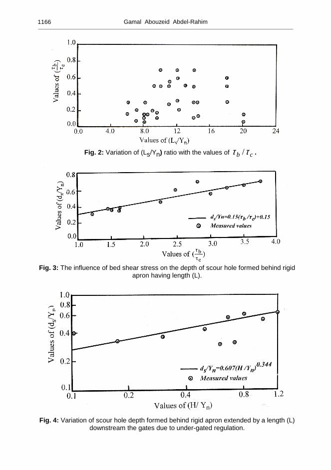
In order to investigate the relationship between the shear stress and the bed motion of soil particles found in sand basin downstream of the regulators, the relative values of scour length Ls/Yn were plotted against the relative values of bed shear stress
( cb ττ / ) as shown in Fig. 2. The data are scattered without any trend or notable
relation. As it is seen, the values of ( cb ττ / ) do not exceed the unity. This confirms
that no bed motion of the solid particles due to the flow motion over the erodible materials found in the sand basin behind the rigid floor of length (Ls). So Ls is considered the minimum length of rigid floor behind the gates of the regulators to prevent scour. On the other side, if an arbitrary length (L) of rigid floor is chosen (L < Ls), a scour hole is formed behind this length of floor with longitudinal length (Xs)
and maximum depth of (ds). As shown in Fig. 3, the relative scour depth (ds/Yn) is
plotted against the relative shear stress ( cb ττ / ). From the figure, it is seen that the
scour hole depth depends on the bed shear stress and the values of ( cb ττ / ) are
always greater than the unity. This means that the bed shear stress due to the flow motion is greater than the critical one for moving the soil particles in the basin behind this length (L) of rigid floor. For the given soil size the functional relationship between ds and cb ττ / may be expressed in linear form as: (11) 15.0 )( 15.0 +=
c
b
n
sY
d
ττ
To be of practical utility and due to the importance of finding out the depth of scour hole (if it is allowed), the measured values of (ds/Yn) are plotted against H/Yn as
shown in Fig. 4. The figure shows the increase of (ds/Yn) values with the increase in
H/Yn values. This is because the increase of the working head difference (H) increases
the flow kinetic energy and consequently the erosion forces. The represented data on logarithmic scales are grouped around a straight line giving the following relationship;
(12) )( 607.0 33.0
nn
sYH
Y
d =
Gamal Abouzeid Abdel-Rahim ________________________________________________________________________________________________________________________________ 1166
Fig. 2: Variation of (Ls/Yn) ratio with the values of cb ττ / .
Fig. 3: The influence of bed shear stress on the depth of scour hole formed behind rigid
apron having length (L).
Fig. 4: Variation of scour hole depth formed behind rigid apron extended by a length (L) downstream the gates due to under-gated regulation.

ESTIMATION OF THE MINIMUM FLOOR LENGTH BEHIND…. ________________________________________________________________________________________________________________________________
1167
Most investigations on the local scour of alluvial channels near rigid aprons are based upon examination of topography of scour holes produced by different hydraulic conditions [2, 7–12]. In the present study, another approach is considered, where the scour reach is represented by both the minimum floor length (Ls) to prevent scour behind the model of three vents regulator or by the sum of an arbitrary length (L < Ls)
and the length of scour hole formed behind it (Xs). For symmetrical flow regulation,
the experimental results of scour reach behind the gates of the model of three-vents regulator represented by the ratio (Ls/Yn) versus the working head difference ratio
(H/Yn) for submerged and free under-gated regulations are shown in Fig. 5.
Obaviously, the data for the submerged regulation clustered around a straight line giving a definite relation between the ratio (Ls/Yn) and the ratio (H/Yn). This
relationship may take the following form;
(13) 0.6 )( 7.11 +=nn
sYH
Y
L
In the case of free regulation and for the given value of H and Yn, it is seen from the
figure that the measured reach of scour is shorter than that of submerged regulation. This may due to the fact that the efficiency of the free hydraulic jump in dissipating the energy is higher than the submerged one. This efficiency increases with the increase of the working head difference. Also, the data confirm the findings from previous researches [15, 17] on the hydraulic jump where they concluded that the length of the roller of submerged jump is longer than that of free jump. This roller increases the intensity of turbulence and consequently the erosion factor. The difference in Ls/Yn ratio is increased with the increase of H/Yn values. It is found the
percentage decrease in Ls/Yn (relative to the submerged case) between the submerged
and free regulations may be equal to (33 H/Yn).
Fig. 5: Variation of Ls/Yn with H/Yn for submerged and free under-gated regulations
(symmetrical case).
Gamal Abouzeid Abdel-Rahim ________________________________________________________________________________________________________________________________ 1168
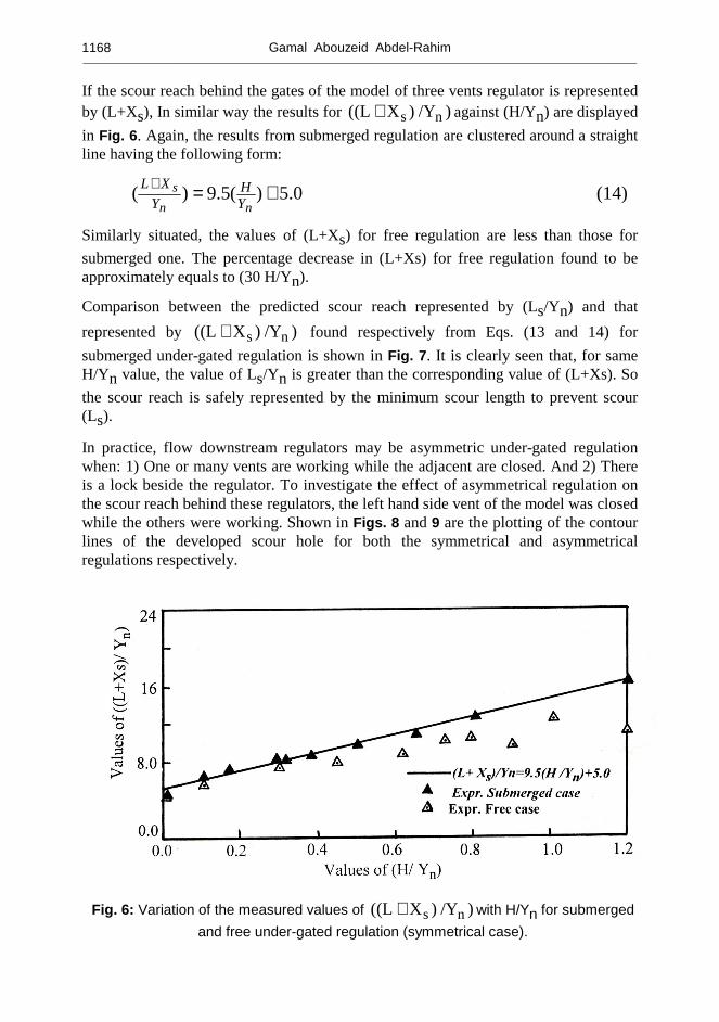
If the scour reach behind the gates of the model of three vents regulator is represented by (L+Xs), In similar way the results for ) /Y)X(L( ns+ against (H/Yn) are displayed
in Fig. 6. Again, the results from submerged regulation are clustered around a straight line having the following form:
(14) 5.0)(5.9)( +=+
nn
sYH
Y
XL
Similarly situated, the values of (L+Xs) for free regulation are less than those for
submerged one. The percentage decrease in (L+Xs) for free regulation found to be approximately equals to (30 H/Yn).
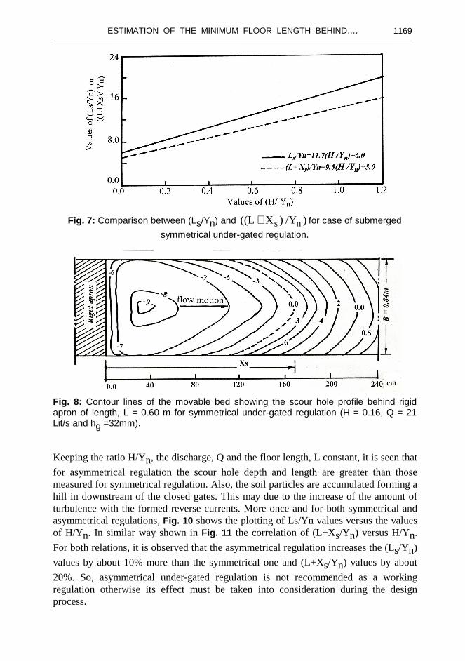
Comparison between the predicted scour reach represented by (Ls/Yn) and that
represented by ) /Y)X(L( ns+ found respectively from Eqs. (13 and 14) for
submerged under-gated regulation is shown in Fig. 7. It is clearly seen that, for same H/Yn value, the value of Ls/Yn is greater than the corresponding value of (L+Xs). So
the scour reach is safely represented by the minimum scour length to prevent scour (Ls).
In practice, flow downstream regulators may be asymmetric under-gated regulation when: 1) One or many vents are working while the adjacent are closed. And 2) There is a lock beside the regulator. To investigate the effect of asymmetrical regulation on the scour reach behind these regulators, the left hand side vent of the model was closed while the others were working. Shown in Figs. 8 and 9 are the plotting of the contour lines of the developed scour hole for both the symmetrical and asymmetrical regulations respectively.
Fig. 6: Variation of the measured values of ) /Y)X(L( ns+ with H/Yn for submerged
and free under-gated regulation (symmetrical case).
ESTIMATION OF THE MINIMUM FLOOR LENGTH BEHIND…. ________________________________________________________________________________________________________________________________
1169
Fig. 7: Comparison between (Ls/Yn) and ) /Y)X(L( ns+ for case of submerged
symmetrical under-gated regulation.
Fig. 8: Contour lines of the movable bed showing the scour hole profile behind rigid apron of length, L = 0.60 m for symmetrical under-gated regulation (H = 0.16, Q = 21 Lit/s and hg =32mm).
Keeping the ratio H/Yn, the discharge, Q and the floor length, L constant, it is seen that
for asymmetrical regulation the scour hole depth and length are greater than those measured for symmetrical regulation. Also, the soil particles are accumulated forming a hill in downstream of the closed gates. This may due to the increase of the amount of turbulence with the formed reverse currents. More once and for both symmetrical and asymmetrical regulations, Fig. 10 shows the plotting of Ls/Yn values versus the values of H/Yn. In similar way shown in Fig. 11 the correlation of (L+Xs/Yn) versus H/Yn.
For both relations, it is observed that the asymmetrical regulation increases the (Ls/Yn)
values by about 10% more than the symmetrical one and (L+Xs/Yn) values by about
20%. So, asymmetrical under-gated regulation is not recommended as a working regulation otherwise its effect must be taken into consideration during the design process.

Gamal Abouzeid Abdel-Rahim ________________________________________________________________________________________________________________________________ 1170
Fig. 9: Contour lines of the movable bed showing the scour hole profile behind rigid apron of length, L = 0.60 m for asymmetrical under-gated regulation (H = 0.16, Q = 21 Lit/s and hg =43mm).
Fig. 10: Comparison between the variation of Ls/Yn with H/Yn for symmetrical and
asymmetrical under-gated submerged regulations.
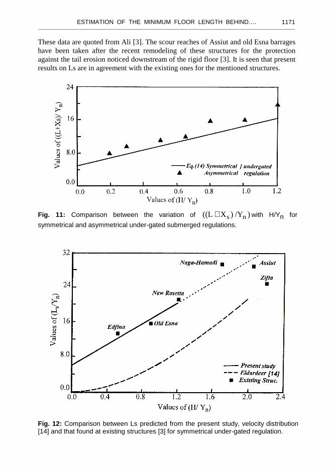
Moreover the present results on (Ls) are depicted in Fig. 12 showing the variation of
(Ls/Yn) values against (H/Yn) values together with the predicted results of El-Dardeer
[14]. Apparently, the scour length obtained from the movable bed presented herein is found to be about 3.6 times that predicted from the velocity distribution method [14]. This means that the erosion depends on the amount of turbulence which is not represented by the direct measurements of the velocity distributions. Also shown in Fig. 12 the existing scour lengths for six barrages found on the River Nile designed previously.
ESTIMATION OF THE MINIMUM FLOOR LENGTH BEHIND…. ________________________________________________________________________________________________________________________________
1171
These data are quoted from Ali [3]. The scour reaches of Assiut and old Esna barrages have been taken after the recent remodeling of these structures for the protection against the tail erosion noticed downstream of the rigid floor [3]. It is seen that present results on Ls are in agreement with the existing ones for the mentioned structures.
Fig. 11: Comparison between the variation of ) /Y)X(L( ns+ with H/Yn for
symmetrical and asymmetrical under-gated submerged regulations.
Fig. 12: Comparison between Ls predicted from the present study, velocity distribution [14] and that found at existing structures [3] for symmetrical under-gated regulation.
Gamal Abouzeid Abdel-Rahim ________________________________________________________________________________________________________________________________ 1172
CONCLUSIONS
The findings from this research may have practical application and the following conclusions may be drawn: 1- Scour reach – represented by (Ls) or (L+Xs)- downstream of a multi-vents
regulator is found to be function of the working head difference (H), the downstream normal flow depth (Yn), the submergence of the under-gated
regulations and the method of regulation (symmetrical or asymmetrical). 2- The minimum floor length (Ls) downstream of the gates of regulator to prevent
scour is longer than the sum of floor length (L< Ls) and the length of scour hole
formed behind it (Xs).
3- Asymmetrical under-gated regulation is not recommended as a working regulation otherwise its effect must be taken into consideration during design process.
4- Depth of scour hole (ds) formed behind an arbitrary length of floor (L < Ls)
depends on the bed shear stresses due to flow motion and the working head difference (H).
REFERENCES
[1] Brdly, J.N., and Peterka, A. J.,”The hydraulic design of stilling basins”, Jour. Of Hyd. Div., ASCE, 82(HY5), Oct. 1957.
[2] Negm, A. M., Abdel-Aal, G. M., Saleh, O. K., and Sauida, M. F.,“ Effect of supercritical flow on scour characteristics downstream of sudden expanding stilling basins”, Egyptian Jour. Of Eng. Scie.& Tech. (EJEST), 6(1), 2002.
[3] Ali, N.A.,” The proper location of floor sill with scour reach downstream of heading-up structure”, Jour. Of Eng. Scie. (JES), Faculty of Eng. Assiut Univ., 23(2), July 1995.
[4] Ismail, H. and Shalasdh, M. S.,”Study of scour below hydraulic structures by means of velocity distribution”, Bulletin of Faculty of Eng., Cairo Univ., 1954.
[5] Abouzeid, G., ”Scour at the abutment of one-vent bridge”, Jour. Of Eng. Scie. (JES), Faculty of Eng. Assiut Univ., 32(3), July 2004.
[6] Johnson, P.,” Reliability-Based pier Scour Engineering”, Jour. Of Hyd. Eng., 118(10), Oct., 1992.
[7] Kamil, H.M., and Karim O.,” Simulation of flow around piers”, J. Hydr. Res.(IAHR), 40(2), 2002.
[8] Roudkivi, A.J., and Ettema, R.” Clear-water scour at cylindrical piers”, Jour. Of Hyd. Eng., 109(3), March 1983.
[9] Youssef, H.,” Anew analytical bridge pier scour equation”, Proc. Of 8th Int. Water Tech. Conf. (IWTC), Alex., Egypt, 2004.
[10] Ali, N.A.,” Scour prediction at submarine pipelined near the sea bed”, Bulletin of Faculty of Eng., Assiut Univ. 24(1), Jan. 1996.
[11] Hemaid, H.S.,” Bed erosion at submarine pipelines exposed to unidirectional water flow”, M. Sc. Thesis, Civil Eng. Dept., Assiut Univ., Egypt, 2000.
ESTIMATION OF THE MINIMUM FLOOR LENGTH BEHIND…. ________________________________________________________________________________________________________________________________
1173
[12] Hassan, M.K.,” Erosion of alluvial bed downstream of a sluice gate”, Ph. D. thesis, Dept of Civil and Structural Eng. (UMIST), U.K. 1985.
[13] Bligh, W.G.,” The practical design of irrigation works”, Constable, 2nd edn., London, 1912, found in Refs. [21 & 30].
[14] El-Dardeer, M.,”Different ways of passing water through the gates of regulators and its effect on scour below”, M. Sc. Thesis, Civil Eng. Dept., Assiut Univ., Egypt, 1986.
[15] Ali, N.A., Abouzeid, G., and Mona, M.,” Study on the internal flow feature through submerged hydraulic jump in sloped bed channels”, Jour. Of Eng. Scie. (JES), Faculty of Eng. Assiut Univ., 33(1), Jan. 2005.
[16] Chatterjee, S.S., and Ghosh, S.N.,” Submerged horizontal jet over erodible bed”, Jour. Of Hyd. Div., ASCE, 106(HY), Nov. 1980.
[17] Govinda Roa, N.S., and Rajaratnam,N.,” The submerged Hydraulic jump”, Jour. Of Hyd. Div., ASCE, 89(HY1), Jan., 1963.
[18] Ragaratnam, N.,”Submerged hydraulic jump”, Jour. Of Hyd. Div., ASCE, 91 (HY4), July 1965.
[19] Leliavesky, S.,” Design of dams percolation and erosion”, Vol. (III), Chapman and Hall LTD., London, 1965.
[20] Shukry, A.,”The efficiency of floor sills under drowned hydraulic jumps”, Jour. Of Hyd. Div., ASCE, 83 (HY3), June 1957.
[21] Rand, W.,” Flow over a vertical sill in an open channel”, Jour. Of Hyd. Div., ASCE, 91 (HY4), July 1965.
[22] Yassin, A.M.,”Design of Irrigation structures (2)”, Lec. Note, Civil Eng. Dept., Assiut Univ. 1984.
[23] Leliavesky, S.,” An introduction to fluvial hydraulics”, Constable & Company LTD., London, 1955.
[24] Ali, N. A.,” A contribution to sediment transportation with reference to hydraulic resistance”, M. Sc. Thesis, Civil Eng. Dept. Assiut Univ., 1978.
[25] Khalil, M. B.,” Hydraulic roughness of channels with rippled-bed”, Bulletin of Science & Tech., Assiut Univ., 1969.
[26] Powel,R.W.,”Flow in channel of definite roughness”, Trans., ASCE, (111), 1946. [27] Rouse, H.,” Critical analysis of open channel resistance”, J. of Hyd. Div., ASCE,
Vol. 91 No. HY.4, July 1965. [28] Khalil, M.B.,” On preserving the sand patterns in river models”, Bulletin of
Science & Tech., Assiut Univ., Vol. 12, 1969. [29] Grade, R.J., Subramabya, K., and Nambudrpad, K.D,” Study of scour around
super dikes”, J. Hydr. Div., ASCE, 87(6), 1961.
Gamal Abouzeid Abdel-Rahim ________________________________________________________________________________________________________________________________ 1174
�� أر��� ��� ش ��� ��ا��ت ا����ط � ا������ �� ا�!�ل ا�د"�# (�)� و&�ع ��� ك
ھ28رو.9E F7G>H8@ذج .AB69 ا.9@?:<=>45-8& ;:879& .5,67 234م ھ/ا ا.-,+ درا'&
JKLM. 5ض:;>OL; عLQ7-& وR &8?2ام أرTU'LV>7;5ك ر,U; . ا.79:9<ا.96@ذج و?e ا.96@ذج . ;dودة V-@اLVت =,ab (cHث _L,Uت( ا.2TU^9م 94[\ 6Q]5ة ;U:2دة ا.L,UYت
.o .2را'& =l7f mOLnG 58bA ھi-j &k8 ;5,6ف، وذ BH;>?5f@_& ذات L[Qع L6Qة _<=V5& ا.L3ع و_5ق ا.9@ازt8'L69. &E ا.L89ه أ;Lم وF7G ا.-@اLVت =,r ظ5وف =p4@H ا.dY3ة
l7f 9@رةw9.8& ا.,5ة واH8.28روx.ا.<ا@U.5ة اjL-; تLVا.-@ا F7G . &:8-[.ة اLyL,9.و )، =r9 درا'& ا.,L.& ا.7bL9U9& و58K )|8+ أن ھL6ك 2fة ط5ق .5459U ا.L89ه أ'Y\ ا.-@اLVت
أو�ھp8Uf@9<; : 242,U. L9 إ.lاr9^3E ا.L<Uرب . ا.5459U. &7bL9U9 ا.L89ه أ'Y\ ا.-@اLVت t7R عLQ F7G &[email protected]ة اY,7. l7H.ا.]@ل ا&_L?�LV l.إ p; L'L3; t7n.ع اL3.ط@ل ھ/ا ا
LVت . تا.-@اLVا.-@ا p; L'L3; t7n.ع اL37. lEل ا�د@[.242 ا,U7_ &8EL].ا L;2,4ث وا./يأ � ھ<=V5& ا.L3ع ا.L3; r9= . &;2TU^9ر�OLUE &E ا.E i:; .p8Uf@9<9,5 .6@ع =V5& ا.L3ع ا.U9,5ك
&E@BT.ا J'@U; \;5.ا)d50 = 0.502 mm .( lEرب أن ا.]@ل ا�دL<U.ا �OLUE 5تxأظ
'L3; t7n.ع اL37. تLVا.-@ا p; L5 وا./ي-yأ L9O5ك دا,U9.ع اL3.ا &V5= 5 .6@ع,E i:; 2,4ث � t7n.ع اL3.ا F7G &[email protected]ة اY,7. l7H.ا.]@ل ا p;&_L?�LV l.ع إL3.ا p; 5ظL69.ا.]@ل ا
� 2,4ث ;:i وا./يo./y و�2 أن ا.]@ل ا�دL37. lEع ا.t7n . ا.p; L'L3; t7n ا.-@اLVتU9,5ك 29U:4 أ'l7f L'L _5ق ا.U@ازن l7f ا.-@اLVت، طE 5459= &345,5 .6@ع =V5& ا.L3ع ا.
lR@= L9y ا.2را'& t<4 � iEAV . ا.L89ه، E@ع ا.dY3ة ا.28xرو.8H8& ا.F7G &E@HU9 ا.-@اLVت=c . أL6bء ا.c89nU ا�L-Ufر _<58bA= /G�4ھL وأ�ا.8wB=&345[.LV &7bL9U; 58w\ ا.L63ط5
ا.U>45-8& و;L3رV �OLUE e; Lx<OLUE &E:� ا.L:9د�ت ا.^3VL& ا'LU6Uج ;>p; &f@9 ا.L:9د�ت .ا.]-8:& و ا.Y69/ة L6Q l7fط5 ا.86\ _<وo./y ا.L69ظ5ة