Estimation of Carbon Coatings Manufactured on Magnesium...
28
3 Estimation of Carbon Coatings Manufactured on Magnesium Alloys Marcin Golabczak Technical University of Lodz, Department of Production Engineering Poland 1. Introduction Magnesium (Mg) is one of the most abundant structural metals on the earth. Magnesium resources are estimated on approximately 1,93% of mass of the earth’s crust and 0,13% of mass of the oceans. Magnesium is present in salt water in form of chlorides (in amount of approximately 1,2 kg/ m 3 ), however in earth crust in form of dolomites composed mainly from carbonates. Magnesium belongs to ultra light metals (1,75 g/ cm 3 ), has silver glossy colour, is soft and ductile, easily reacts chemically with other substances (e.g.: oxygen, nitrogen, carbon dioxide or water). Unfortunately, magnesium has a lot of undesirable properties such as poor corrosion and wear resistance, what limits its use in many usages especially for outdoor applications. For this reason pure magnesium is rarely used in technique, however with other metals (e.g.: aluminum, zinc, manganese, cerium, zirconium and rare earth metals) forms alloys, which are very attractive constructional material. Because of this magnesium alloys found a plethora of applications in various branches of industry where reduction in weight is of importance (Gray & Luan, 2002). These alloys are used in aerospace, automobile (Kawalla et al., 2008) and electronic industries, for manufacturing of sporting goods, high-speed boats, submarines, household equipment, etc. (Fig. 1). The main advantages of magnesium alloys are: the high strength, weight ratio, high thermal conductivity, small heat extensibility, good welding characteristics and high functional integrity, which allow to produce near-net-shape elements as well as good machinability (Hawkins, 1993). However, magnesium alloys have also certain disadvantages. The most troublesome of them is the high susceptibility to corrosion (especially galvanic corrosion), which contributes to dwindling of their size and reduces mechanical durability. As to protect magnesium alloys from corrosion, at present various methods for the fabrication of protective films have been used (Ishizaki et al., 2009). Other disadvantages of magnesium alloys comprise their weak wear resistance, a drop in durability at high temperature and interference of electromagnetic field. The aforementioned faults considerably reduce the area of application of this material. Presented studies aimed at elimination of the listed drawbacks by means of covering of magnesium alloy with special carbon coatings. Plasma Activated Chemical Vapor Deposition (PACVD) method has been used for this purpose. Optimum conditions of this process have been determined and the material properties of the carbon coatings characterized. www.intechopen.com
Transcript of Estimation of Carbon Coatings Manufactured on Magnesium...
3
Estimation of Carbon Coatings Manufactured on Magnesium Alloys
Marcin Golabczak Technical University of Lodz,
Department of Production Engineering Poland
1. Introduction
Magnesium (Mg) is one of the most abundant structural metals on the earth. Magnesium
resources are estimated on approximately 1,93% of mass of the earth’s crust and 0,13% of
mass of the oceans. Magnesium is present in salt water in form of chlorides (in amount of
approximately 1,2 kg/ m3), however in earth crust in form of dolomites composed mainly
from carbonates. Magnesium belongs to ultra light metals (1,75 g/ cm3), has silver glossy
colour, is soft and ductile, easily reacts chemically with other substances (e.g.: oxygen,
nitrogen, carbon dioxide or water). Unfortunately, magnesium has a lot of undesirable
properties such as poor corrosion and wear resistance, what limits its use in many usages
especially for outdoor applications. For this reason pure magnesium is rarely used in
technique, however with other metals (e.g.: aluminum, zinc, manganese, cerium, zirconium
and rare earth metals) forms alloys, which are very attractive constructional material.
Because of this magnesium alloys found a plethora of applications in various branches of
industry where reduction in weight is of importance (Gray & Luan, 2002). These alloys are
used in aerospace, automobile (Kawalla et al., 2008) and electronic industries, for
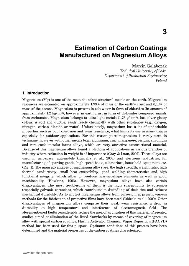
manufacturing of sporting goods, high-speed boats, submarines, household equipment, etc.
(Fig. 1). The main advantages of magnesium alloys are: the high strength, weight ratio, high
thermal conductivity, small heat extensibility, good welding characteristics and high
functional integrity, which allow to produce near-net-shape elements as well as good
machinability (Hawkins, 1993). However, magnesium alloys have also certain
disadvantages. The most troublesome of them is the high susceptibility to corrosion
(especially galvanic corrosion), which contributes to dwindling of their size and reduces
mechanical durability. As to protect magnesium alloys from corrosion, at present various
methods for the fabrication of protective films have been used (Ishizaki et al., 2009). Other
disadvantages of magnesium alloys comprise their weak wear resistance, a drop in
durability at high temperature and interference of electromagnetic field. The
aforementioned faults considerably reduce the area of application of this material. Presented
studies aimed at elimination of the listed drawbacks by means of covering of magnesium
alloy with special carbon coatings. Plasma Activated Chemical Vapor Deposition (PACVD)
method has been used for this purpose. Optimum conditions of this process have been
determined and the material properties of the carbon coatings characterized.
www.intechopen.com
Special Issues on Magnesium Alloys
42
a) b)
c) d)
Fig. 1. Examples of use magnesium alloys: a) mobile phone housing, b) wheelcase, cover and
flange of differential gear, c) magnesium alloy wheels, or “mag wheels” used on racing cars,
d) body front of camera
2. Methods of manufacturing of protective coatings on magnesium alloys
In literature there are many different methods and techniques of manufacturing of
protective and decorative coatings on magnesium alloys (Gray & Luan, 2002). Taking into
consideration physical processes used in these techniques we can classify seven main
methods of manufacturing of protective and decorative coatings on magnesium alloys,
which have been presented in figure 2. These include electrochemical plating, conversion
coatings, hydride coatings, anodizing, vapour-phase processes, laser cladding and polymer
coatings (Golabczak, 2005). All these methods are characterized by different complexity of
used technological processes, costs of realization these processes, degree of environmental
nuisance and surroundings, as well as functional properties of manufactured coatings and
range of their applications. As yet it has not been developed effective method assuring
complete corrosion resistance of magnesium alloys and decorative virtues of manufactured
coatings. Because of the increasing interest in magnesium alloys in different fields of
industry, it is justified to carry out research on elaboration of a “new” methods fulfilling all
these requirements in superlative degree.
www.intechopen.com

Estimation of Carbon Coatings Manufactured on Magnesium Alloys
43
Electroplated coatings 1
Polymer coatings 7
Laser surfacealloying 6
Conversion coatings 2
Hydride coatings 3 Anodizing 4
Gas-phase deposition 5
Chemical Vapour deposition CVD
5.2
In fluoride bath
4.1
In alcaline bath
4.2
Plasma 4.3
Thermal spray deposition
5.1
Physical Vapour deposition PVD
5.3
Diffusion coatings
5.4
Ion implantation
5.5
Painting coatings
7.1
Powder coatings
7.2
Epoksydation 7.3
Sol-gel process 7.4
Electrochemical polymerization
7.5
Plasma polymerization
7.6
Zinc immersion 1.1
Nickel plating 1.2
From noble metals
1.3
Alternative 1.4
Chromate 2.1
Phosphate-permanganate
2.2
Fluorozirconate 2.3
Stannate 2.4
TECHNIQUES OF COATINGS MANUFACTURING ON
MAGNESIUM ALLOYS
Fig. 2. Techniques of coatings manufacturing on magnesium alloys
3. Characteristic of carbon coatings
Carbon coatings have been characterized by very attractive functional properties, especially
by decorative and protective, which predestine them for application in many fields. At
present, there are many methods and techniques which are used for their manufacturing,
among them dominate techniques exploitative plasma, ion beams and methods of
unconventional synthesis (Robertson, 2002). Diversity of these methods and wide range of
applied parameters have essential influence on quality of manufactured carbon coatings.
Taking into account the structure of manufactured carbon coatings we can identify four
basic groups:
diamond – inclusive diamond films - DF and polycrystalline diamond coatings – PCD,
which are composed of atoms of configuration sp3, nanocrystalline diamond coatings
– NCD, tetrahedral carbon ta-C and amorphous diamond a-D coatings;
graphite – amorphous carbon coatings of graphite structure e.g. pyrolytic graphite coatings which are obtained in vacuum pyrolysis process;
carbyne - inclusive -carbyne contains, which contains acetylic bonds (–CC–) and are
also called as polyacetynele carbyne contains, -carbyne coatings, which contains
cumulative double bond (=C=C=) also called as polycumulene carbyne coatings;
diamond like carbon - inclusive diamond like carbon coatings – DLC – which are mixture
of amorphous or nanocrystalline of carbon containing fraction of sp3 bonds - typical
for diamond structure, fraction of sp2 bonds – typical for graphite and sp1.
Above mentioned structures of carbon coatings have found application for deposition of
many constructional materials used for example in: medicine for manufacturing of implants
(Niedzielski et al., 1997), tool industry for increasing of durability and wear resistance of
cutting edges (Olszyna & Smolik, 2004), jewellery industry for manufacturing of decorative
www.intechopen.com

Special Issues on Magnesium Alloys
44
coatings (Clapa et al., 2001), for coating of polymers used in aerospace industry (Hawkins,
1993), etc. This wide field of application of carbon coatings justifies usefulness their
exploitation for covering of magnesium alloys. Among many analyzed methods of
manufacturing of carbon coatings especially attractive seems to be PACVD (Plasma
Activated Chemical Vapour Deposition) method, elaborated in Technical University of Lodz
– Poland. This method is particularly useful for manufacturing carbon coatings mentioned
above with predominated part of diamond in these coatings (Niedzielski et al., 1997).
4. The stand for manufacturing of carbon coatings by PACVD method
For investigations AZ31 magnesium alloy samples have been used. AZ31 (ASTM
designation) is very commertial alloy used in die casting and plastic forming. The chemical
composition (in wt%) of AZ31 is: 2.83 %Al, 0.8% Zn, 0.37% Mn and 0.002% Cu (Kuc et al.,
2008). Carbon coatings have been deposited on this alloy by PACVD method, which has
relied on decomposition of methane in electric field with high frequency of 13.56 MHz,
obtained at the pressure of approximately 12 Pa in a working chamber (Golabczak, 2005).
Processes of PACVD have been realized in the stand presented in figure 3. It has consisted
of the chamber of water cooled plasma reactor, the high frequency electrode fixed to the
plate of the base and connected through the condenser (the latter provided the negative
potential of self-polarization), generator of high frequency (facilitated production of plasma
with high density and maintained the frequency at the constant level), vacuum system and
systems of measurement and control. Carbon coatings have been deposited on AZ31
magnesium alloy in two steps comprising the process of ionic digestion of their surface
followed by the process of synthesis of these coatings. Parameters of these steps are shown
in table 1.
Fig. 3. The view of the system used for deposition of carbon coatings by PACVD method
www.intechopen.com

Estimation of Carbon Coatings Manufactured on Magnesium Alloys
45
Parameter Ionic digestion of the surface Process of coating deposition
Feed gas CH4 CH4
Pressure in a working
chamber 8 ÷ 10 Pa 12 Pa
Time of process - t 4 min 5 ÷ 9 min
Gas flow rate - V 5 cm3/ min 20÷60 cm3/ min
Table 1. Optimum parameters of PACVD process
5. Preparation of samples made of magnesium alloys for investigations
Polishing process of samples made of AZ31 magnesium alloy has been carried out using
Phoenix Beta 2 (Buehler-Germany) dual platen grinder-polisher machine equipped with
Vector power head (Fig. 4) and specimens holder for single force for 3-6 specimens up to
max ø 25 mm, according to holder selected. Thus 3 to 6 specimens can be prepared under
reproducible conditions. The Buehler grinder-polisher machine has had stepless rotation
speed (from 30 to 600 rpm) and the power head settings of control time, pressure (up to
200 N), speed and direction and automatic start and stop system. Vector power head
upgrades the Beta 2 grinder-polisher machine to from manual operation to semi-automatic
operation, increasing productivity and specimen consistency. This stand is on equipment of
Department of Production Engineering of Technical University of Lodz - Poland laboratory.
Fig. 4. The overall view of the Beta 2 dual platen grinder-polisher machine equipped with
Vector power head and specimens holder
The samples made of AZ31 hp magnesium alloy of diameter ø 20 mm from TECHNO-
COAT Oberflaechentechnik GmbH, Zittau-Germany have been used for investigations. The
main technological requirement of technological process was to prepare samples of a low
surface roughness and removal impurities from their surface layer. For this purpose the
technological process of abrasive machining including following grinding and polishing
operations, using Buehler equipment and accessories has been elaborated:
www.intechopen.com

Special Issues on Magnesium Alloys
46
- two stage grinding of samples on grinder equipped with self adhesive BuehlerMet
silicon carbide abrasive paper; in sequential stages of grinding the granularity of SiC
material has been diversified using accordingly: in first stage silicon carbide grits size 26
µm and in second stage silicon carbide grits size 26 µm; the grinding process has been
carried out using wax;
- lapping of samples using medium hard woven silk cloth VerduTex and Buehler MetaDi
diamond suspension of diamond grains size 3 µm; MetaDi is a oil-base product,
particularly suitable for soft and water-sensitive materials, absolutely water free with
tight distribution of synthetic, monocrystalline diamonds which have a great number of
cutting faces. This offers a particularly high material removal rate and scratch-free
surfaces of samples;
- final polishing of samples using self-adhesive soft synthetic pad ChemoMet and
aluminium oxide (Al2O3) final polishing suspension MasterPrep (grains size ø 0,05 µm);
- washing of samples in ethyl alcohol of high purity (99,9 %) Chem Land using ultrasonic
washer Polsonic – Sonic 1.
The technological conditions of realized operations of grinding and polishing of AZ31
magnesium alloy samples have been shown in table 2.
Process
stages
Abrasive
surface
Type of abrasive
material
Lubricant
type
Process
time
[min]
Feed
force
[N/ cm2]
Rotation
speed of
platen V
[m/ s]
Grinding
of sample
surface
BuehlerMet
silicon
carbide
abrasive
paper
Silicon carbide SiC
P 600 (grits size ø
26 µm)
Wax 5 10 6
BuehlerMet
silicon
carbide
abrasive
paper
Silicon carbide SiC
P 1200 (grits size ø
15 µm)
Wax 1 5 3
Lapping
Medium hard
woven
silkcloth
VerduTex
Monocrystalline
diamond
suspension MetaDi
-oil based (grains
size ø 3 µm)
Oil-based
polishing
extander
Buehler
AutoMet
Lapping
Oil
5 2.5 2
Polishing
Soft synthetic
pad
ChemoMet
Aluminium oxide
(Al2O3) final
polishing
suspension
MasterPrep (grains
size ø 0,05 µm)
– 3 2,5 1
Table 2. Conditions of technological process of magnesium alloy samples preparation
www.intechopen.com

Estimation of Carbon Coatings Manufactured on Magnesium Alloys
47
Elaborated technological process has ensured suitable preparation of samples, in range of
required roughness parameters and their proper purity (including removal of machining
products). The surface of polished samples has had silver, glossy colour and no visible tool
marks.
6. Experimental investigations
Experimental investigations have included determination of technological parameters of the
process of manufacturing of carbon coatings on AZ31 magnesium alloy using PACVD
method and test of operational properties of coatings manufactured in this process. For
arrangement of technological parameters of PACVD process the investigation object model
has been accepted, on which affects variable input quantities (controllable), constant
quantities and factors of jamming. Modelling setting-up of investigation conditions,
inclusive of: variable and constant input quantities, factors of jamming of PACVD process
and output quantities have been presented in figure 5.
Variable input quantities Output quantities
Electrode potential
Ei – relative index of identified carbon forms in coating
PACVD process time
Working gas flow
Surface layer parameters:
Ra, Rz, Rm, Rp, Rv, Wa, Wt, Wp, Wv
Assessment parameters of coatings functional properties: - coating thickness - nanohardness - wear resistance - corrosion resistance - decorative properties - adhesion
INVESTIGATIONSOBJECT:
carbon coatings on magnesium alloy
AZ31
Factors of jamming:
1. Inaccuracy of settings of input quantities
2. Temperature in working chamber3. Pressure in working chamber 4. Inaccuracy of settings of output
quantities
Constant input quantities:
1. Working gas 2. Pressure in working chamber 3. Sample material and dimension 4. Output state of surface layer 5. Sample ion eatching parameters
Fig. 5. Modelling setting-up of investigation conditions
Input quantities and areas and their range of variables have been determined basing on
technological possibilities of test stand for manufacturing of carbon coatings using PACVD
method and preliminary investigation results (Golabczak, 2005). Results of preliminary tests
have shown, that polarization potential values of high frequency electrode should not
exceed voltage of 1000 V and time of PACVD process 12 minutes. Overdraft of these values
has caused excessive heating of samples made of magnesium alloy and their burning. As
www.intechopen.com

Special Issues on Magnesium Alloys
48
output quantities the set of parameters useful both for identification of manufactured carbon
coatings on magnesium alloy samples in PACVD process and assessment of their functional
properties (Fig. 5). Determined investigation conditions, range of variables and test step
have been shown in table 3.
Range of variables and input quantities of PACVD process
Input
quantities
Range
of variables
and test step
Polarization potenctial
U [V]
Time of
PACVD process
t [min]
Working gas
flow
V [cm3/ min]
Ground level 800 7 40
Test step 100 2 20
Upper level 900 9 60
Lower level 700 5 20
Constant input quantities
No. Name of quantity Value/ determination
1 Working gas -methane CH4
2 Pressure in working chamber 12 Pa
3 Samples dimension Ø 20x2 mm
4 Preparation of sample surface
layer
According to procedure depicted in point
No. 5
Table 3. Investigation conditions and range of variables of input quantities of manufacturing
process of carbon coatings using PACVD method
Taking into consideration limitation of costly and labour-intensive experiment designs, the
planned fractional experiment 2n-1 type has been accepted, in which number of experiments
has been equal to 4 (Golabczak, 2005). Design matrix for this type of experiment has been
presented in table 4.
No. of
sample
Variable input quantities
X1
Polarization potenctial
of electrode
U [V]
X2
Time of PACVD
process
t [min]
X3
Working
gas flow
V [cm3/min]
1 +
2 +
3 + +
4 + +
+ upper level of input variable (according to data in table 3)
ground level of input variable (according to data in table 3)
Table 4. Plan of fractional experiment 2n-1 type of manufacturing of carbon coatings
www.intechopen.com

Estimation of Carbon Coatings Manufactured on Magnesium Alloys
49
7. Experimental results
Experiments have included optimization of technological parameters of PACVD process of deposition of carbon films and characterization of their material properties. To determine the optimum conditions of PACVD process, series of tests have been realized according to the fractional experiment 2n-1 type (Golabczak, 2005). The studies of material properties of carbon coatings deposited on AZ31 magnesium alloy have comprised identification of these coatings, measurement of their nanohardness and thickness and determination of their geometrical microstructure of surface. Also tribologic measurements of hard carbon coatings, determination of their corrosion resistance and adhesion have been realized.
7.1 Identification of carbon coatings deposited on AZ 31 magnesium alloy Identification of hard carbon coatings deposited on the surface of AZ31 magnesium alloy has been determined on the basis of their Raman spectra (Golabczak, 2005). For this purpose, the mathematical modeling of fitting of Gaussian peaks of the identified carbon phases to the Raman spectra has been performed (Golabczak, 2005). Exemplary results of Raman spectrum evaluation with using Gaussian profile have been shown in figure 6.
Gaussian profile fitting to the Raman spectrum
0
5000
10000
15000
20000
25000
30000
35000
40000
950 1050 1150 1250 1350 1450 1550 1650 1750 1850 1950Raman shift [cm-1]
Relative intensity [-]
0
1500
3000
4500
6000
7500
9000
10500
12000Relative intensity [-]
Fitted spectrum with 3*sigma error
Experimental data direct
Base line
Experimental data without base-line
Diamond (nanocrystalline)
Graphite alpha
Graphite beta
Fullerenes
Nanotubes
Fitted spectrum
Unrecognized (amorphic carbon?)
Rings: antracenes, fenantrenes,etc.
Chains from hydrocarbons
Fig. 6. Results of Raman spectrum evaluation with using Gaussian profile
The contents of the identified carbon phases in the deposited carbon coatings have been
determined on the basis of the relative index - Ei, described by the following equation (1):
i ip
is i
p x dxAE
A p x dx (1)
www.intechopen.com

Special Issues on Magnesium Alloys
50
where: Api - surface area between the baseline and the curve of fitting to the plot for the
carbon phases identified in the coating, calculated by the method of numerical integration;
As - the summary surface area between the baseline and the curve of fitting to Raman
spectrum, calculated by the method of numerical integration (Golabczak, 2007). The quality
of identified carbon forms, found in coatings deposited through the successive experimental
trials has been determined on the basis of the accepted mathematical model used for fitting
the Gaussian peaks spectra to Raman spectra. For this purpose, the relative index Ei has
been calculated (according to equation 1). The relative index Ei determines the content of
individual carbon forms in the deposited coatings. The graphical interpretation of this
method has been shown in figure 7, which presents the relative content of diamond in the
deposited carbon coating, attained under optimum PACVD process conditions.
Concept of measurement of diamond-like structure content
in the layer imposed on a light alloy
0
2000
4000
6000
8000
10000
12000
14000
16000
18000
1000 1100 1200 1300 1400 1500 1600 1700 1800 1900Raman shift [cm-1
]
Relative intensity
Area under total fittedRaman spectrum
Area under "diamond-like" peak
Diamon content = ADIAMOND PEAK / ATOTAL
Fig. 7. The concept of measurement of the “diamond-like” structure content in the carbon
coating on a light alloy
Results of computing of the relative index Ei, obtained for each specimen prepared within
the scope of the planned experiment, have been shown in figure 8.
Analysis of results obtained for individual specimens produced within the scope of the
planned experiment (specimens 1÷4), revealed that the diamond phase (Ei=0.40÷0.48) and
alfa-graphite phase (Ei=0.20÷0.35) have dominated in the deposited coatings. Also other
carbon phases have been identified, such as beta-graphite- (Ei=0.003÷0.013), fullerens
(Ei=0.11÷0.22), nanotubes (Ei of approximately 0.034) and other, including some unidentified
www.intechopen.com

Estimation of Carbon Coatings Manufactured on Magnesium Alloys
51
forms (Ei=0.006÷0.068), rings (Ei of approximately 0.008), and chains (Ei=0.018÷0.12), but
their contents have been minor. Optimization of deposition conditions (specimen 5) has
shown that the rise in contents of diamond phase (to Ei=0.54) in the coatings has been
achievable. The latter content of diamond phase in the coating has been reached under the
following PACVD process conditions: U=900V, t=8min, and V=60cm3/ min.
1
2
3
4
5
DiamondGraphite
alpha
Graphite
beta
FullerenesNanotubes
0,00
0,10
0,20
0,30
0,40
0,50
0,60
Ei index
Test number
Carbon allotropes
Efficiency of different
carbon forms deposition
Fig. 8. Comparison of values of the relative index Ei for carbon phases identified in carbon
coatings deposited on magnesium alloy specimens obtained within the scope of the planned
experiments of PACVD process
7.2 Measurements of nanohardness of carbon coatings deposited on AZ31 magnesium alloy Nanohardness of carbon coatings has been measured using Nano Test 600 meter (Micro
Materials Ltd., Great Britain) equipped with a diamond pyramidal penetrator (Golabczak,
2005). The measurements of nanohardness have been conducted at the penetrating force (F)
of 0.1–0.6 mN (extorted by the penetrator) and the rate of F increase (dF/ dt) of 0.02 mN/ s.
Values of nanohardness of hard carbon coatings, measured by using the pyramidal
penetrator, have been calculated as follows (2):
n 2p
FH
24,5h (2)
www.intechopen.com

Special Issues on Magnesium Alloys
52
where: Hn – nanohardness of the outer layer [GPa], F – the penetrating force [N], hp –
indentation made by the penetrator [m]. Representative results of nanohardness
measurements of the examined hard carbon coatings deposited on AZ31 magnesium alloy
have been shown in figure 9.
Comparison of nanohardness investigation results
0
3
5
8
10
13
15
18
20
23
25
0,00E+00 5,00E-09 1,00E-08 1,50E-08 2,00E-08 2,50E-08 3,00E-08 3,50E-08 4,00E-08 4,50E-08 5,00E-08Depth of penetration [m]
Nanohardness [GPa]
AZ31 magnesium alloy with carbon layer
AZ31 magnesium alloy
Fig. 9. Comparison of the nanohardness of AZ31 magnesium alloy protected by the carbon
coating deposited under optimum conditions of PACVD process and the specimen without
this coating
The latter presents the difference between the nanohardness of AZ31 magnesium alloy
protected by the carbon coating deposited under optimum conditions of PACVD process
and the alloy without this coating. These results provide evidence that the nanohardness of
AZ31 magnesium alloy protected by the carbon coating deposited by the PACVD method
has been considerably higher (24 GPa) than that of the alloy without the coating (0.8 GPa).
7.3 Determination of thickness of carbon coating The thickness of hard carbon coatings has been determined by the method of direct
profilography using the highly precise Taylor Hobson profilographometer (Golabczak, 2005,
2010). To achieve the accurate results of measurements, the carbon coatings have been
deposited only on selected fragments of the examined samples of magnesium alloy.
Therefore, some parts of their surface have been protected by quartz plates during synthesis
of the coatings (Fig. 10). Thus the examined surfaces of magnesium alloy has contained the
fragments coated by the carbon coating and free from the latter. Results of these
measurements are collected in figure 11. The mean value (from 5 distinct measurements) of
the thickness of a carbon coating has been approximately equal to 220 nm.
7.4 Determination of geometrical microstructure of surface and morphology of surface layer of carbon coatings Presented investigation results concern comparison of geometrical microstructure
parameters of surface and morphology of carbon coating, manufactured on AZ31
magnesium alloy samples using PACVD method, with analogous parameters of samples
www.intechopen.com

Estimation of Carbon Coatings Manufactured on Magnesium Alloys
53
zone of measurements surface without carbon coating
surface with carbon coating
Fig. 10. The image of the surface of a specimen of magnesium alloy AZ31 prepared for the
measurements of carbon coating thickness and the zone of measurements carried out by
profilography method
Fig. 11. Results of measurements of the thickness of carbon coating deposited on magnesium
alloy AZ31 carried out by the method of direct profilography; the thickness of carbon
coating (h) of 220 nm
without carbon coating, prepared for deposition process (after polishing process).
Investigation range has included estimation of carbon coatings manufactured in optimum
conditions of PACVD process (sample No. 5). Geometrical microstructure of carbon coating
surface has been estimated basing on roughness and waviness parameters of surface in 2D and
3D configuration, however morphology of carbon coating basing on measurements of atomic
force microscope - AFM and images of scanning electron microscope - SEM. The profile
measurements have been carried out in Department of Production Engineering of Technical
University of Lodz laboratory, using profilometer type PGM-1C IOS. Samples for profile
measurements have been prepared in the same way like in case of thickness measurement of
carbon coating (point No. 7.3). It has ensured objectivity of measurement results. Exemplary
profile measurements results of samples in 2D configuration have been presented in figure 12
and 14, however in 3D configuration in figure 13 and 15. The values of roughness and
waviness parameters of samples surfaces have been placed in suitable profilograms and have
referred to their average value from five tests of profile measurement.
www.intechopen.com

Special Issues on Magnesium Alloys
54
Ra=0.05Rz=0.44
Wt=0.29Wa=0.06
a)
b)
Fig. 12. Profilograms of roughness (a) and waviness (b) in 2D configuration of AZ31
magnesium alloy surface after polishing process
a)
Ra 3D = 0.06Rm3D = 1.01 Rp 3D = 0.44 Rv 3D = -0.57
Wa3D = 0.12Wt 3D = 0.76 Wp3D = 0.36 Wv3D = -0.41
b)
Fig. 13. Profilograms of roughness (a) and waviness (b) in 3D configuration of AZ31
magnesium alloy surface after polishing process
Roughness parameters analysis of investigated samples in 2D configuration (Fig. 12 and 14) has shown insignificant degradation of roughness of samples surfaces with carbon coating manufactured in PACVD process, compared with samples surfaces after polishing process. It has been certified increase of surface roughness, which has carried out accordingly: Ra increase equel to 0,01 µm and Rz increase equel to 0,08 µm. However measurements carried out in 2D configuration have not revealed significant differences in values of surface waviness parameters. Roughness parameters analysis of investigated samples in 3D configuration (Fig. 13 and 15) has shown larger values of Ra, Wa and Wt parameters of investigated samples. Tendency of these changes has been like in 2D configuration
www.intechopen.com

Estimation of Carbon Coatings Manufactured on Magnesium Alloys
55
Ra=0.06Rz=0.52
Wt=0.27Wa=0.06
a)
b)
Fig. 14. Profilograms of roughness (a) and waviness (b) in 2D configuration of AZ31
magnesium alloy surface with manufactured carbon coating
a)
b)
Ra 3D = 0.07Rm3D = 1,23 Rp 3D = 0.41 Rv 3D = -0.51
Wa3D = 0.10Wt 3D = 0.67 Wp3D = 0.42 Wv3D = -0.64
Fig. 15. Profilograms of roughness (a) and waviness (b) in 3D configuration of AZ31
magnesium alloy surface with manufactured carbon coating
measurements. Analysis of profilograms of surface roughness and waviness in 3D
configuration has also revealed favourable influence of manufacturing of carbon coating
using PACVD method to levelling of maximum profile elevation, expressed by a Ra
parameter and maximum profile cavities, expressed by a Rv parameter. Favourable changes
observed in above-mentioned measurements have been caused by random deposition of
different forms of carbon forms (identified in point No. 7.1) on surface of AZ31 magnesium
alloy during PACVD method. Morphology assessment of investigated samples surfaces has
concerned comparison of SEM and AFM images of their surface layers, which has been
shown in figure 16 and 17. These images have revealed significant changes in their
www.intechopen.com

Special Issues on Magnesium Alloys
56
morphology of surface layer. Images of samples surfaces without carbon coatings obtained
both by SEM and AFM method (Fig. 16 a and 17a) have shown presence of distinct tool
marks caused by polishing process, which have been visible in form of irregular scratches
on surface. SEM images of samples surfaces with manufactured carbon coating (Fig. 16 b)
have been characterized by mosaic, irregular structure imaging different carbon forms in
manufactured coating. Presence of these forma have been confirmed by AFM images. These
different forms of carbon in manufactured coatings has had significant influence on their
colours. Exemplary AFM image of surface of AZ31 magnesium alloy surface with carbon
coating has been presented in figure 17 b.
a) b)
Fig. 16. Images of AZ31 magnesium alloy samples surfaces obtained by scanning electron
microscope - SEM: a) surface after polishing, b) surface with carbon coating
a) b)
Fig. 17. Images of AZ31 magnesium alloy samples surfaces obtained by atomic force
microscope - AFM: a) surface after polishing, b) surface with carbon coating
7.5 Tribologic measurements of carbon coatings Tribologic measurements have relied on tests of rubbing interaction between rectangular
specimens of AZ31 magnesium alloy covered by the carbon coating and deprived of this
www.intechopen.com

Estimation of Carbon Coatings Manufactured on Magnesium Alloys
57
layer with the cylindrical rubbers (Golabczak, 2005). The rubbers have been prepared from
three different materials such as hydrogenated rubber butadiene-acrylonitrile – HNBR,
poly(methylmetacrylate) – PMMA (plexsiglass), and poly(tetrafluoroethylene) – PTFE
(teflon). Dimensions of rectangular specimens of magnesium alloy have been 10x4x5 mm.
The cylindrical rubbers has had the diameter of 35 mm and width of 10 mm. Tribologic tests
have been conducted using Tribometer T-05 under the following conditions: normal load of
the rubber – 6 N, the rubbing speed – 3.67 cm/ s, time of test duration – 2 h, frequency of
recording of measurements – 2E+14, and ambient temperature (T) of 20.7°C. Representative
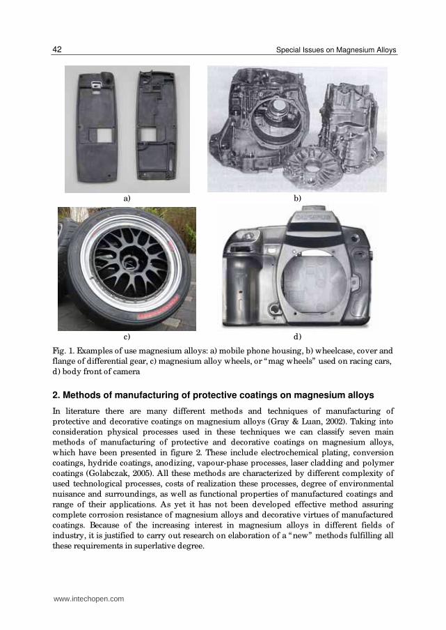
results of tribologic measurements have been shown in figure 18-19. They have presented
differences in the total friction energy and volumetric wear of the examined specimens
during the test. The displayed results have provided evidence that the carbon coatings
deposited on magnesium alloy have considerably improved their properties. They have
both reduced the total energy of friction and enhanced their resistance to wear. The
experiments have revealed that the total energy of friction of the listed above specimens
with carbon coatings, has been considerably lower and reached: 44% for the rubber one,
130% for the plexiglass rubber and 440% for that made of teflon. Carbon coatings have had
also significantly decreased the total volumetric wear of the examined samples of
magnesium alloy. The relative increase in wear resistance has been: 660% – in case of the
rubber rubber, 540% – for the plexiglass rubber and 800% – for the teflon one.
Butadiene-acrylonitrile
rubber
Polymethyl
methacrylate (PMMA)
Polytetrafluoroethylene
(PTFE)
Magnesium alloy
Carbon layer
0
500
1000
1500
2000
2500
Total friction energy [J]
Material of contrasample
Type of surface
Grindability test - comparison
Fig. 18. Comparison of values of the total energy of friction determined by tribologic
measurements for specimens made of AZ31 magnesium alloy protected by carbon coating
and without the latter
www.intechopen.com
Special Issues on Magnesium Alloys
58
Butadiene-acrylonitrile
rubber
Polymethyl methacrylate
(PMMA)
Polytetrafluoroethylene
(PTFE)
Magnesium alloy
Carbon layer0,000
0,010
0,020
0,030
0,040
0,050
0,060
Cavity volume [mm3]
Material of contrasample
Type of surface
Grindability test - comparison
Fig. 19. Comparison of volumetric wear of the specimens made AZ31 of magnesium alloy
(one covered by carbon coating and the second – without this coating) determined by
tribologic measurements
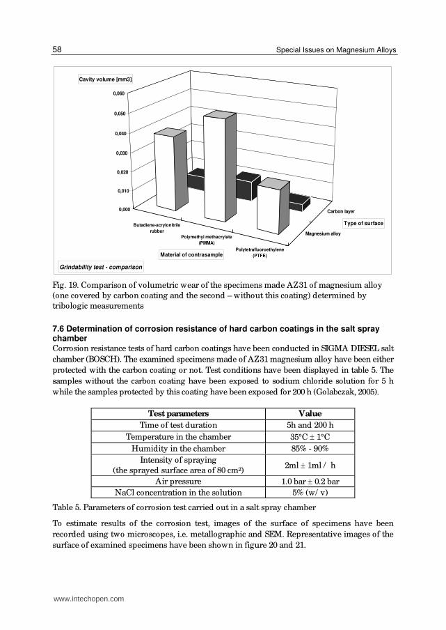
7.6 Determination of corrosion resistance of hard carbon coatings in the salt spray chamber Corrosion resistance tests of hard carbon coatings have been conducted in SIGMA DIESEL salt
chamber (BOSCH). The examined specimens made of AZ31 magnesium alloy have been either
protected with the carbon coating or not. Test conditions have been displayed in table 5. The
samples without the carbon coating have been exposed to sodium chloride solution for 5 h
while the samples protected by this coating have been exposed for 200 h (Golabczak, 2005).
Test parameters Value
Time of test duration 5h and 200 h
Temperature in the chamber 35°C 1°C
Humidity in the chamber 85% - 90%
Intensity of spraying
(the sprayed surface area of 80 cm2) 2ml 1ml / h
Air pressure 1.0 bar 0.2 bar
NaCl concentration in the solution 5% (w/ v)
Table 5. Parameters of corrosion test carried out in a salt spray chamber
To estimate results of the corrosion test, images of the surface of specimens have been
recorded using two microscopes, i.e. metallographic and SEM. Representative images of the
surface of examined specimens have been shown in figure 20 and 21.
www.intechopen.com
Estimation of Carbon Coatings Manufactured on Magnesium Alloys
59
b)a)
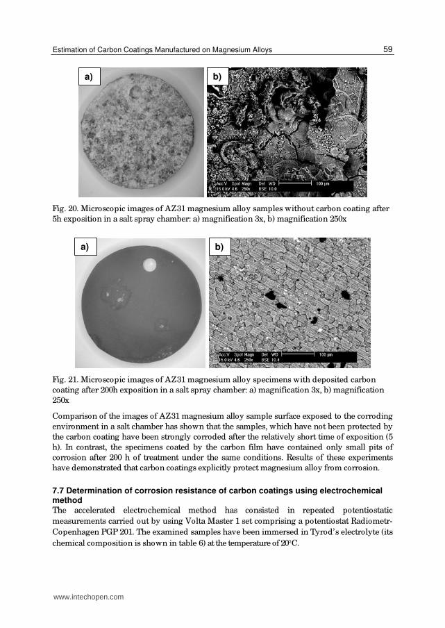
Fig. 20. Microscopic images of AZ31 magnesium alloy samples without carbon coating after
5h exposition in a salt spray chamber: a) magnification 3x, b) magnification 250x
b)a)
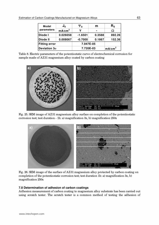
Fig. 21. Microscopic images of AZ31 magnesium alloy specimens with deposited carbon
coating after 200h exposition in a salt spray chamber: a) magnification 3x, b) magnification
250x
Comparison of the images of AZ31 magnesium alloy sample surface exposed to the corroding
environment in a salt chamber has shown that the samples, which have not been protected by
the carbon coating have been strongly corroded after the relatively short time of exposition (5
h). In contrast, the specimens coated by the carbon film have contained only small pits of
corrosion after 200 h of treatment under the same conditions. Results of these experiments
have demonstrated that carbon coatings explicitly protect magnesium alloy from corrosion.
7.7 Determination of corrosion resistance of carbon coatings using electrochemical method The accelerated electrochemical method has consisted in repeated potentiostatic
measurements carried out by using Volta Master 1 set comprising a potentiostat Radiometr-
Copenhagen PGP 201. The examined samples have been immersed in Tyrod’s electrolyte (its
chemical composition is shown in table 6) at the temperature of 20C.
www.intechopen.com

Special Issues on Magnesium Alloys
60
NaCl
[g/ dm3]
CaCl2
[g/ dm3]
KCl
[g/ dm3]
NaH2PO4
[g/ dm3]
MgCl26H2O
[g/ dm3]
NaHCO
[g/ dm3]
pH
8.00 0.20 0.20 0.05 0.10 1.00 6.9
Table 6. Chemical composition of Tyrod’s electrolyte
Modeling of phenomena occurring at the contact interface between the conductor (metal)
and the electrolyte has been based on the standard Butler-Volmer equation (Golabczak,
2008). It is a half-empirical equation and characterizes the rate of electric charge transfer
through the interface of phases: metal-electrolyte. This rate depends, first of all, on the
difference of potentials and its sign (positive or negative) at this interface. The analysis of
current flow through the medium which is far from the state of equilibrium cannot be done
without the model of Butler-Volmer. The model has based on an electric nonlinear circuit
has been proposed to determine the flow of current in the wide range of potential values.
This circuit contains some elements responsible for individual physical phenomena that take
place during potentiostatic measurements. The scheme of this substitute circuit has been
shown in figure 22.
RS1 RS2
UD1 D2
01 02
I I1 I2
Fig. 22. The structure of proposed model in the form of the nonlinear electric circuit with
lumped constants
The proposed model consists of two branches characterizing anodic and cathodic currents.
Relationships between the elements of the model shown in figure 22 and phenomena
occurring at the interface conductor-electrolyte are as follows:
diodes D1 and D2 that are fundamental elements of the proposed model correspond to
the exponential components of Butler-Volmer equation that are responsible for
diffusion ,
resistors RS1 and RS2 are responsible for the transfer of electric charge carriers and are
particularly important at higher values of voltage U,
voltage generators 01 and 02 are responsible for the difference in potentials at the
contact interface for anodic and cathodic parts of the characteristics.
www.intechopen.com

Estimation of Carbon Coatings Manufactured on Magnesium Alloys
61
Equations describing the substitute electric circuit (Fig. 22) are as follows:
- for the anodic branch (left parts of descending curves in figure 23 and 24):
1
D1
q mU
k T1 01j j e 1
(3)
1 1 1 01S DR j U Ψ U (4)
- for the cathodic branch (right parts in ascending curves in figure 11 and 12):
2
2
2 02 1D
q mU
k Tj j e
(5)
2 2 2 02S DR j U Ψ U (6)
The total current flowing through the interface is the sum of anodic current and cathodic
current:
1 2j j j (7)
where: q- the elementary charge of an electron, expressed in [C] [A·s], q=1.6022·10-19 C;
k- Boltzman constant, expressed in [J/ K] [kg·s2/ m2·K], k=1.3807·10-23 J/ K;
T- the temperature of the contact interface [K];
j01, j02 – the density of saturation currents, expressed in [mA/ cm2];
RS1, RS2 – resistances representing the phenomenon of electron transfer, expressed in [];
m1, m2 – coefficients dependent on division of currents and valences of ions in the
electrolyte, dimensionless quantities.
Electric parameters of this model for individual potentiostatic curves (Tafel curves) have been
identified by means of the least square method and by resolving the system of nonlinear
equations by the gradient method. The obtained parameters are effective estimators of the true
model parameters. Results of potentiostatic measurements have been plotted in figure 23 and
24. Intercepts of curves presenting the voltage on diodes with OX axis correspond to potentials
on the interface metal-solution. The values of electric parameters that have been calculated for
the assumed models are presented in table 7 and 8. On completion of potentiostatic
measurements the surface of the examined samples has been subjected to SEM analysis.
Examples of the recorded images have been shown in figure 25 and 26. Analysis of results of
electrochemical studies has revealed that deposition of the carbon coating on the surface of
AZ31 magnesium alloy significantly dislocated and increased the difference in potentials
(corrosion potential increased) at the interface between the metal and solution (Fig. 24) as
compared to the reference sample without the coating (Fig. 23). It provides evidence of the
beneficial effect of carbon coating deposited on this alloy because the barrier protecting the
latter from electrochemical corrosion has been increased.
Also SEM analysis of the surface of the examined samples has confirmed this desirable
impact (Fig. 25 - 26). Only single dark spots (probably very small corrosion pits) have been
visible at the surface of the samples coated by carbon coating (Fig. 26) whereas harmful
results of electrochemical corrosion have been visible on the whole surface of unprotected
AZ31 magnesium alloy (Fig. 25).
www.intechopen.com

Special Issues on Magnesium Alloys
62
-0.75
-0.50
-0.25
0.00
0.25
0.50
0.75
1.00
1.25
-2.75 -2.50 -2.25 -2.00 -1.75 -1.50 -1.25 -1.00 -0.75 -0.50 -0.25 0.00 0.25Voltage [V]
Current density
[mA/cm2]
Diode 1: Current
Diode 1: Voltage
Diode 2: Current
Diode 2: Voltage
Model
Data
Fig. 23. Potentiostatic curve of electrochemical corrosion for AZ31 magnesium alloy free of
carbon coating
-0.75
-0.50
-0.25
0.00
0.25
0.50
0.75
1.00
1.25
-2.75 -2.50 -2.25 -2.00 -1.75 -1.50 -1.25 -1.00 -0.75 -0.50 -0.25 0.00 0.25Voltage [V]
Current density
[mA/cm2]
Diode 1: Current
Diode 1: Voltage
Diode 2: Current
Diode 2: Voltage
Model
Data
Fig. 24. Potentiostatic curve of electrochemical corrosion for AZ31 magnesium alloy
protected by carbon coating
J0 0 m RS
mA/cm2 V -
Diode I 0.009145 -1.6622 0.4276 1092.46
Diode II 0.000100 -1.6482 0.9607 643.96
mA/cm2
Model
parameters
4.027E-03
5.280E-02
Fitting error
Deviation 3
Table 7. Electric parameters of the potentiostatic curve of electrochemical corrosion for
sample made of AZ31 magnesium alloy free of carbon coating
www.intechopen.com
Estimation of Carbon Coatings Manufactured on Magnesium Alloys
63
J0 0 m RS
mA/cm2 V -
Diode I 0.026058 -1.6501 0.3588 892.26
Diode II 0.008067 -0.7000 0.1867 152.36
mA/cm27.720E-03
Model
parameters
Fitting error 7.947E-05
Deviation 3
Table 8. Electric parameters of the potentiostatic curve of electrochemical corrosion for
sample made of AZ31 magnesium alloy coated by carbon coating
a)
b)
Fig. 25. SEM image of AZ31 magnesium alloy surface on completion of the potentiostatic
corrosion test; test duration - 1h: a) magnification 3x, b) magnification 250x
a)
b)
Fig. 26. SEM image of the surface of AZ31 magnesium alloy protected by carbon coating on
completion of the potentiostatic corrosion test; test duration 1h: a) magnification 3x, b)
magnification 250x
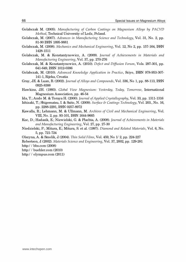
7.8 Determination of adhesion of carbon coatings Adhesion measurement of carbon coating to magnesium alloy substrate has been carried out
using scratch tester. The scratch tester is a common method of testing the adhesion of
www.intechopen.com
Special Issues on Magnesium Alloys
64
coatings to substrates. For this purpose a special diamond intender is used. The load on the
diamond causes stresses to be increased at the interface between the coating and the
substrate that can result in delamination of the coating to occur. The load at which the
coating first delaminates is called the critical load. For measurement of carbon coating a
small diamond intender with a radius of r=200 m has been applied. During test a diamond
intender has been scratched across the coated surface of a substrate at a constant velocity
whilst a load has been applied with a constant loading rate F. Applied load F has been
changed in the 10 to 30 N range and the load rating has been equal to 5 N. Adhesion
assessment of carbon coating to magnesium alloy substrate has been done basing on optical
microscope images of wear tracks of worn surfaces of the sample. The critical load of
intender Fc, at which occurs cohesion loss has been assumed as criterion of adhesion of the
coating to substrate. For ascertainment of this fact the comparison of microscopic images of
wear tracks of worn surface of AZ31 magnesium alloy protected by carbon coating has been
done (Fig. 27).
a)
b)
c)
Fig. 27. Characteristic images of wear tracks of worn surface of sample after „scratch test”
obtained using optical microscope (magnification 50 x): a) F= 10 N, b) F= 20 N, c) F= 25 N
Presented investigation results have concerned adhesion of carbon coatings manufactured
in optimum conditions of PACVD process, i.e. in conditions of test No. 5. Basing on
investigations carried out it has been certified that critical load of intender Fc at which
occurs no cohesion loss between carbon coating and magnesium alloy substrate has been
www.intechopen.com

Estimation of Carbon Coatings Manufactured on Magnesium Alloys
65
equal to 20 N (Fig. 27 b). Further increase load of intender (to 25 N) has caused separation of
carbon coating from magnesium alloy substrate. This state has been presented in figure 27 c,
where sharply outlined surface and white zone of magnesium alloy have been visible.
8. Conclusion
Investigations carried out have confirmed that Plasma Activated Chemical Vapour
Deposition (PACVD) method enables deposition of protective carbon coatings on AZ31
magnesium alloy. Elaborated technological polishing process of AZ31 magnesium alloy
samples has ensured suitable preparation their surfaces, in range of required roughness
parameters and their proper purity. Investigations results have confirmed that content of
diamond phase in these coatings has been very high. Its relative index Ei has been equal to
0.54 and has depended on PACVD process conditions. Nanohardness of magnesium alloy
AZ31 protected by the carbon coating has been considerably higher (24 GPa) than that of the
alloy without this coating (0.8 GPa). The measured thickness of a carbon coating has been
approximately equel to 220 nm. The displayed results have provided evidence that the
carbon coatings deposited on magnesium alloys have considerably improved their
properties. They have both reduced the total energy of friction and enhanced their resistance
to wear. The experiments have revealed that the total energy of friction of the listed above
specimens with carbon coatings, has been considerably lower and reached: 44% for the
rubber one, 130% for the plexiglass rubber and 440% for that made of teflon. Carbon
coatings have also significantly decreased the total volumetric wear of the examined
samples of magnesium alloy. The relative increase in wear resistance has been: 660% – in
case of the 540% - for the plexiglass and 800% - for the teflon one. Experiments have
demonstrated that carbon coatings explicitly protect magnesium alloy from “salt spray”
corrosion and electrochemical corrosion. Basing on investigations carried out it has been
certified that critical load of intender Fc at which occurs no cohesion loss between carbon
coating and magnesium alloy substrate has been equel to 20 N. Manufactured carbon
coatings apart from very attractive operational properties mentioned above, have had also
decorative properties. They have had gold glossy colour what can be useful in making of
jewellery. Moreover, manufactured carbon coatings have been characterized by very good
biocompatibility (because of high content of pure diamond). This property is especially
important in protection of implants surfaces. Presented results have indicated that the
studies should be continued in order to improve PACVD method and produce carbon
coatings on specimens with more complex shapes and on internal surfaces of specimens
made of magnesium alloys.
9. Acknowledgement
This work has been partially financed by the Grant No. 3 T08C 06826 from Polish
Committee for Scientific Research.
10. References
Clapa, M.; Mitura, S; Niedzielski, P; Karczemska, A. & Hassard, J. (2001). Diamond and Related Materials, Vol. 10, No. 3, pp. 1121-1124
www.intechopen.com
Special Issues on Magnesium Alloys
66
Golabczak M. (2005). Manufacturing of Carbon Coatings on Magnesium Alloys by PACVD Method, Technical University of Lodz, Poland.
Golabczak, M. (2007). Advances in Manufacturing Science and Technology, Vol. 31, No. 2, pp.
81-90 ISSN 1895-9881
Golabczak, M. (2008). Mechanics and Mechanical Engineering, Vol. 12, No 2, pp. 157-164, ISSN
1428-1511
Golabczak, M. & Konstantynowicz, A. (2009). Journal of Achievements in Materials and Manufacturing Engineering, Vol. 37, pp. 270-276
Golabczak, M. & Konstantynowicz, A. (2010). Defect and Diffusion Forum, Vols. 297-301, pp.
641-649, ISSN 1012-0386
Golabczak, M. (2010). Advanced Knowledge Application in Practice, Sciyo, ISBN 978-953-307-
141-1, Rijeka, Croatia
Gray, J.E. & Luan, B. (2002). Journal of Alloys and Compounds, Vol. 336, No 1, pp. 88-113, ISSN
0925-8388
Hawkins, J.H. (1993). Global View Magnesium: Yesterday, Today, Tomorrow, International
Magnesium Association, pp. 46-54
Ida, T.; Ando M. & Toraya H. (2000). Journal of Applied Crystallography, Vol. 33, pp. 1311-1316
Ishizaki, T.; Shigematsu, I. & Saito, N. (2009). Surface & Coatings Technology, Vol. 203., No. 16,
pp. 2288-2291, ISSN 0257-8972
Kawalla, R.; Lehmann, M. & Ullmann, M. Archives of Civil and Mechanical Engineering, Vol.
VIII, No. 2, pp. 93-101, ISSN 1644-9665
Kuc, D.; Hadasik, E.; Niewielski, G. & Plachta, A. (2008). Journal of Achievements in Materials and Manufacturing Engineering, Vol. 27, pp. 27-30
Niedzielski, P.; Mitura, E.; Mitura, S. et al. (1997). Diamond and Related Materials, Vol. 6, No.
5, pp. 721-724
Olszyna, A. & Smolik, J. (2004). Thin Solid Films, Vol. 459, No 1/ 2, pp. 224-227
Robertson, J. (2002). Materials Science and Engineering, Vol. 37, 2002, pp. 129-281
http:/ / bbs.com (2008)
http:/ / buehler.com (2010)
http:/ / olympus.com (2011)
www.intechopen.com

Special Issues on Magnesium AlloysEdited by Dr. Waldemar Monteiro
ISBN 978-953-307-391-0Hard cover, 128 pagesPublisher InTechPublished online 12, September, 2011Published in print edition September, 2011
InTech EuropeUniversity Campus STeP Ri Slavka Krautzeka 83/A 51000 Rijeka, Croatia Phone: +385 (51) 770 447 Fax: +385 (51) 686 166www.intechopen.com
InTech ChinaUnit 405, Office Block, Hotel Equatorial Shanghai No.65, Yan An Road (West), Shanghai, 200040, China
Phone: +86-21-62489820 Fax: +86-21-62489821
Magnesium is the lightest of all the metals and the sixth most abundant on Earth. Magnesium is ductile and themost machinable of all the metals. Magnesium alloy developments have traditionally been driven byrequirements for lightweight materials to operate under increasingly demanding conditions (magnesium alloycastings, wrought products, powder metallurgy components, office equipment, nuclear applications, flares,sacrificial anodes for the protection of other metals, flash photography and tools). The biggest potential marketfor magnesium alloys is in the automotive industry. In recent years new magnesium alloys have demonstrateda superior corrosion resistance for aerospace and specialty applications. Considering the information above,special issues on magnesium alloys are exposed in this book: casting technology; surface modification ofsome special Mg alloys; protective carbon coatings on magnesium alloys; fatigue cracking behaviors of castmagnesium alloys and also, magnesium alloys biocompatibility as degradable implant materials.
How to referenceIn order to correctly reference this scholarly work, feel free to copy and paste the following:
Marcin Golabczak (2011). Estimation of Carbon Coatings Manufactured on Magnesium Alloys, Special Issueson Magnesium Alloys, Dr. Waldemar Monteiro (Ed.), ISBN: 978-953-307-391-0, InTech, Available from:http://www.intechopen.com/books/special-issues-on-magnesium-alloys/estimation-of-carbon-coatings-manufactured-on-magnesium-alloys

© 2011 The Author(s). Licensee IntechOpen. This chapter is distributedunder the terms of the Creative Commons Attribution-NonCommercial-ShareAlike-3.0 License, which permits use, distribution and reproduction fornon-commercial purposes, provided the original is properly cited andderivative works building on this content are distributed under the samelicense.