ESTIMATION AND MEASUREMENT OF LEAK FLOW THROUGH … · LEAK FLOW THROUGH SLITS/PRE-CRACKED ......
14
2 Issue no. 281 June 2007 ESTIMATION AND MEASUREMENT OF LEAK FLOW THROUGH SLITS/PRE-CRACKED PIPES S. K. Bandyopadhyay S. K. Bandyopadhyay S. K. Bandyopadhyay S. K. Bandyopadhyay S. K. Bandyopadhyay, B. Ghosh, V , B. Ghosh, V , B. Ghosh, V , B. Ghosh, V , B. Ghosh, V. M. Shanware, D. Mukhopadhyay . M. Shanware, D. Mukhopadhyay . M. Shanware, D. Mukhopadhyay . M. Shanware, D. Mukhopadhyay . M. Shanware, D. Mukhopadhyay, H. G. Lele, A. K. Ghosh and H. S. Kushwaha H. G. Lele, A. K. Ghosh and H. S. Kushwaha H. G. Lele, A. K. Ghosh and H. S. Kushwaha H. G. Lele, A. K. Ghosh and H. S. Kushwaha H. G. Lele, A. K. Ghosh and H. S. Kushwaha Reactor Safety Division Introduction The basic philosophy of Leak-Before-Break (LBB), as the name implies, is based on detection of Leak from a pipeline, carrying a high-energy liquid, Before it Breaks. The LBB methodology is now accepted as a justifiable approach in eliminating the traditional Double-Ended Guillotine Breaks (DEGB), in the design of high energy piping component where it is applicable. In the design of a nuclear reactor, sufficient safety features are incorporated, to limit the consequences of a DEGB. But the establishment of LBB concept has been helpful in the reduction of a large number of structures required for pipe whip restraints and jet shields. This is also beneficial in terms of cost reduction and radiation exposure. Hence, it is extremely important to detect and measure leak, from any high energy piping in a nuclear reactor. LBB is ensured by demonstrating three levels of safety assessment against DEGB. Level 1 is inherent in the design philosophy of ASME Sec. III, which is normally followed in piping design. Ductile and tough materials are widely used in nuclear power plant piping, because of their high resistance to catastrophic rupture. The design is carried out with a well defined factor of safety on code-specified probability strength. The demonstration of Level 2 safety, consists of postulating a surface crack, which may go undetected during non destructive testing. It is then shown through fatigue analysis, that there is insignificant crack growth of this surface crack, during the entire reactor life. In Level 3 safety assessment, a through-wall leaking crack is postulated, at the location of maximum stress with worst material properties. The size (length) of the through-wall crack should be such that, the calculated leakage rate of fluid discharged from the crack under normal operating load, is equal to the immediate shutdown action limit. An elasto-plastic fracture mechanics assessment is performed, to demonstrate that adequate margins exist against the onset of unstable crack extension. The minimum margins which must be met are twice on the size (length) of crack and a square root of two on the extreme load, acting on the pipe, containing the through-wall crack. Generally, it has been observed that a leak rate of 0.05 kg/s is easilydetectable by suitable instrumentation. On this, applying the US Nuclear Regulatory Commission’s safety factor of 10, the reliable leak detection capability is considered to be 0.5 kg/s. A manual reactor shutdown is initiated on this flow value, to bring down the reactor power. The concept of LBB is now widely used to design the Primary Heat Transport (PHT) system piping, of a nuclear power plant. This approach has been used to design the 500 MWe Indian Pressurized Heavy Water Reactors (PHWRs) at Tarapur [1].
Transcript of ESTIMATION AND MEASUREMENT OF LEAK FLOW THROUGH … · LEAK FLOW THROUGH SLITS/PRE-CRACKED ......

2 I s s u e n o . 2 8 1 J u n e 2 0 0 7
ESTIMATION AND MEASUREMENT OFLEAK FLOW THROUGH
SLITS/PRE-CRACKED PIPES
S. K. BandyopadhyayS. K. BandyopadhyayS. K. BandyopadhyayS. K. BandyopadhyayS. K. Bandyopadhyay, B. Ghosh, V, B. Ghosh, V, B. Ghosh, V, B. Ghosh, V, B. Ghosh, V. M. Shanware, D. Mukhopadhyay. M. Shanware, D. Mukhopadhyay. M. Shanware, D. Mukhopadhyay. M. Shanware, D. Mukhopadhyay. M. Shanware, D. Mukhopadhyay,,,,,H. G. Lele, A. K. Ghosh and H. S. KushwahaH. G. Lele, A. K. Ghosh and H. S. KushwahaH. G. Lele, A. K. Ghosh and H. S. KushwahaH. G. Lele, A. K. Ghosh and H. S. KushwahaH. G. Lele, A. K. Ghosh and H. S. Kushwaha
Reactor Safety Division
Introduction
The basic philosophy of Leak-Before-Break (LBB), as thename implies, is based on detection of Leak from apipeline, carrying a high-energy liquid, Before it Breaks.The LBB methodology is now accepted as a justifiableapproach in eliminating the traditional Double-EndedGuillotine Breaks (DEGB), in the design of high energypiping component where it is applicable. In the designof a nuclear reactor, sufficient safety features areincorporated, to limit the consequences of a DEGB. Butthe establishment of LBB concept has been helpful in thereduction of a large number of structures required forpipe whip restraints and jet shields. This is also beneficialin terms of cost reduction and radiation exposure. Hence,it is extremely important to detect and measure leak,from any high energy piping in a nuclear reactor.
LBB is ensured by demonstrating three levels of safetyassessment against DEGB. Level 1 is inherent in the designphilosophy of ASME Sec. III, which is normally followedin piping design. Ductile and tough materials are widelyused in nuclear power plant piping, because of their highresistance to catastrophic rupture. The design is carriedout with a well defined factor of safety on code-specifiedprobability strength. The demonstration of Level 2 safety,consists of postulating a surface crack, which may goundetected during non destructive testing. It is then shown
through fatigue analysis, that there is insignificant crackgrowth of this surface crack, during the entire reactorlife. In Level 3 safety assessment, a through-wall leakingcrack is postulated, at the location of maximum stresswith worst material properties. The size (length) of thethrough-wall crack should be such that, the calculatedleakage rate of fluid discharged from the crack undernormal operating load, is equal to the immediateshutdown action limit. An elasto-plastic fracturemechanics assessment is performed, to demonstrate thatadequate margins exist against the onset of unstable crackextension. The minimum margins which must be metare twice on the size (length) of crack and a square rootof two on the extreme load, acting on the pipe,containing the through-wall crack.
Generally, it has been observed that a leak rate of 0.05kg/s is easilydetectable by suitable instrumentation. Onthis, applying the US Nuclear Regulatory Commission’ssafety factor of 10, the reliable leak detection capabilityis considered to be 0.5 kg/s. A manual reactor shutdownis initiated on this flow value, to bring down the reactorpower. The concept of LBB is now widely used to designthe Primary Heat Transport (PHT) system piping, of anuclear power plant. This approach has been used todesign the 500 MWe Indian Pressurized Heavy WaterReactors (PHWRs) at Tarapur [1].

3I s s u e n o . 2 8 1 J u n e 2 0 0 7
A systematic study on LBB has been initiated at the ReactorSafety Division to determine two important parameters:namely Crack Opening Area (COA) and critical leak flowrate through cracks/slits. A computer code namedCCCCCrack_SSSSSlit FFFFFlow AAAAAnalysis (C_SFA) has been developedwith analytical models, to determine COA and leakageflow rate. The developed leakage flow rate model isvalidated [2] against published data [3,4,5] specific toPressurized Water Reactors. In order to further validatethe physical models for PHWRs and Advanced HeavyWater Reactor (AHWR), an experimental facility has beenset up at Heat Power Laboratory, at the MechanicalEngineering Department, Jadavpur University, Kolkata,under the Board for Research in Nuclear Sciences (BRNS).Prof. S.K. Saha and Dr S. Das were the principalinvestigators of this facility.
The experimental facility consists of High Pressure andHigh Temperature (HPHT) loop, pressurized by nitrogensystem and a test section, housing the slit/ pre-crackedpipe. The HPHT system is designed to operate for apressure and temperature range of 70 to 90 bar and200° C - 270° C respectively, having a maximum leakageflow rate of 0.8 kg/s. This condition simulates the reactorcondition of existing PHWRs and the cold leg of proposedAHWR. Prediction of crack flow with physical modelsinvolves uncertainty in COA determination andconequently in critical mass flow rate prediction. Tominimize the uncertainty level in the prediction, it wasalso decided to carry out experiment with pipes havingslits with definite flow geometry.
The loop is well instrumented, to measure the requiredparameters, to validate the physical models developed atthe Reactor Safety Division. The typical feature of thisfacility is that, during the course of the experiment,pressure and temperature of the system is maintainedconstant at the crack/slit upstream as expected forleakages, within the leak handling system capacity of aNuclear Power Plant (NPP). Similar experiments have beenconducted by the US Nuclear Regulatory Commission
[3,4,5] for assessing the safety and integrity of highenergy piping systems.
Analytical modeling of code C_SFA
Determination of COA and leakage flow rate throughcracks/slits are the two aspects of this code, for whichmodels are developed. Following is a brief description ofthese two models.
Crack Opening Area (COA)For determination of crack opening area, several modelse.g., Tada-Paris Model [6], Bertholome et al [7] model,Kastner et al [8] can be used. Tada-Paris model is themost widely used model for calculating COA. In thismodel, crack opening area depends on the load actingon the crack plane, material property e.g. Young’sModulus of the piping material, pipe dimensions, cracksize and finally on the crack orientation. Forcircumferential crack in tension and bending, crack-opening areas are calculated as follows:
)'(2
θπσ ttt IE
RA ⎟⎟
⎠
⎞⎜⎜⎝
⎛= , )'(
2
θπσ bbb IE
RA ⎟⎟
⎠
⎞⎜⎜⎝
⎛=
.... (1)
where It and Ib are integrals arising in energy method(castigliano’s theorem); θ’ is effective semi crack angle,A, Crack Opening Area is the sum of areas due to tensionand bending loads.
A= At + Ab .... (2)
where At and Ab are the crack opening areas due totensile (σt ) and bending (σb ) loads respectively.
4 I s s u e n o . 2 8 1 J u n e 2 0 0 7
Semi-crack angle θ ’ is modified to effective crack angle(θ ’eff) to take into account the small plasticity effect.
... (3).
Following assumptions are considered for Tada-Parismodel:
a) The formula has been derived for R/t ratio equal to 10.
b) Estimation formula is expected to yield slightlyoverestimated results for R/t near 10.
c) For smaller R/t ratio, the degree of overestimatewould increase.
Leak Flow Rate Estimation
This model consists of two parts. The first part deals withpressure drop formulation in the flow path (cracks andslits) and the second part deals with models for criticalmass flux estimation. For estimation of the flow rate,these two models work interactively through an iterativeprocedure.
Pressure Drop Formulation
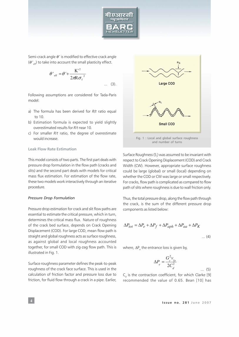
Pressure drop estimation for crack and slit flow paths areessential to estimate the critical pressure, which in turn,determines the critical mass flux. Nature of roughnessof the crack bed surface, depends on Crack OpeningDisplacement (COD). For large COD, mean flow path isstraight and global roughness acts as surface roughness,as against global and local roughness accountedtogether, for small COD with zig-zag flow path. This isillustrated in Fig. 1.
Surface roughness parameter defines the peak-to-peakroughness of the crack face surface. This is used in thecalculation of friction factor and pressure loss due tofriction, for fluid flow through a crack in a pipe. Earlier,
Surface Roughness (Sr) was assumed to be invariant withrespect to Crack Opening Displacement (COD) and CrackWidth (CW). However, appropriate surface roughnesscould be large (global) or small (local) depending onwhether the COD or CW was large or small respectively.For cracks, flow path is complicated as compared to flowpath of slits where roughness is due to wall friction only.
Thus, the total pressure drop, along the flow path throughthe crack, is the sum of the different pressure dropcomponents as listed below:
Kaaaphfetot PPPPPP Δ+Δ+Δ+Δ+Δ=Δ
... (4)
where, ΔPe the entrance loss is given by,
... (5)Cd is the contraction coefficient, for which Clarke [9]recommended the value of 0.65. Bean [10] has
2f
2
effR2
'K''
σπθθ +=
Fig. 1 : Local and global surface roughnessand number of turns
2
2
2d
loce C
vGP =Δ

5I s s u e n o . 2 8 1 J u n e 2 0 0 7
recommended Cd = 0.95 for tight cracks. An averagevalue of 0.85 for Cd has been adopted for the model.
ΔP f is the pressure drop due to friction given by,
.... (6)
where friction factor f is given by John et al [11],
... (7)
Pressure drop accounted for change in acceleration fromphase change is given by,
... (8)
This expression can be integrated from Z = Zf (ie. x = 0)to the critical condition at the throat (x = xc) and isexpressed as,
... (9)
The acceleration pressure drop due to area change alongthe flow path is given by,
... (10)
where Ka is the pressure loss coefficient due to change offlow area.
Finally, KPΔ is the pressure drop due to bends, turns
and protrusions in the flow path that occur in actualcracks. For slits this term becomes zero.
...(11)K is the loss coefficient for turns and bends [2].
The critical pressure Pc is the difference between the initial
stagnation pressure Po and total pressure drop ΔPtot.
...(12).For a given stagnation condition and crack geometry,the critical mass flow rate (Gc) is calculated by iterativesolution of equation (4) and equation (12). The values ofGc and Pc are assumed to be correct when the relativeerrors between two successive iterations are of a lessthan a specified value.
Critical Flow ModelsThe critical mass flux (Gc ) is estimated with various criticalflow models namely Burnel Model, HomogeneousNon-equilibrium Models (HNMs) and HomogeneousFrozen Models (HFMs). Based on the thermal-hydraulicconditions, these models are used. Following is a briefdiscussion of these models :
Burnel’s ModelThis model [12] takes into account the delay caused innucleation which results in high flow rates throughnozzles and orifices. The critical mass flux is given by,
... (13)
where ‘c’ is given by Weisman and Tentner [13]
)286.6/exp(/8645.00.1 32.12 barPsatc σσ−=
... (14)where all properties are based on upstream condition.
Homogeneous Non equilibrium Model
In Henry’s [13] homogeneous non-equilibrium model,high energy flow through cracks and slits, modeled ascritical flow through a pipe, are characterized by thefollowing attributes: a large L/DH ratio, a relatively smallresidence time and a large relative surface roughness.Henry [15, 16] had simplified his earlier model based onthe following assumptions,
( ) ( )[ ]glllo
h
f
hfocf
vvxvv
D
LL
D
LvfGP
−++−
⎟⎟
⎠
⎞
⎜⎜
⎝
⎛ −+=Δ
ββ1
5.0 2
2
866.0log89.3 ⎟⎟⎠
⎞⎜⎜⎝
⎛−=
r
h
S
Df
[ ]glcaph
xvvxdGdP +−= )1(2
( )[ ]lolcgcclccaph vvvxvGP −−+=Δ 2
logaaavGKP 2
21=Δ
locK vKGP 2
2
1=Δ
totocPPP Δ−=
[ ] 5.0))1((2 satslc PcPG −−= ρ


7I s s u e n o . 2 8 1 J u n e 2 0 0 7
A brief description of the component/systems is given inthe following paragraphs and Fig. 4 shows some of thecomponents of this facility.
Buffer chamber
The Buffer Chamber (BC) is made of a seamless pipe( 600 NB Sch. 100 and 5.5 m in height ) of grade
(ASTM-A106 Gr. B) with anaverage thickness of 42 mm.The volume of this vessel is1.25m3. A helical path isprovided on the outer surfaceof this vessel for thermic fluidflow. The buffer chamberwater is heated by ThermicFluid. A jacket on BC outersurface with helical path,provides the flow path for thethermic fluid. Excessive heatloss is prevented by a thicklayer of insulation applied tothe outer surface of BC.Safety valves and rupture diskat the top of BC take care ofany sudden overpressures.
Nitrogen System
Constant primary systemstagnation pressure ismaintained with the help ofNitrogen system containingforty eight N22222 cylinders at140 bar pressure connectedto a common manifold. Thepressure in the BC ismaintained with a pressurecontroller and a pressurecontrol valve.
Fig. 2 : Schematic of the Leak Test Facility at Heat Power Lab.,Mechanical Engg. Dept., Jadavpur University
Thermic Fluid Heating System (TFHS)
The Thermic Fluid Heating System consists of a heatingsection, circulating pump and a blower. Thermic fluid(thermibol-59, boiling point 350°C) is heated by burningHigh Speed Diesel (HSD) in a burner of the heating section.The system is designed for 5 bar pressure and 350oCtemperature.

8 I s s u e n o . 2 8 1 J u n e 2 0 0 7
Fig. 3 : Techno-feasibility study with RELAP5 simulation model

9I s s u e n o . 2 8 1 J u n e 2 0 0 7
WWWWWater Tater Tater Tater Tater Treatment Plant (WTP)reatment Plant (WTP)reatment Plant (WTP)reatment Plant (WTP)reatment Plant (WTP)
An iron removing filter and water softener have beenincorporated to ensure that water used for the experimentshas the following specifications:
a) Iron < 0.20 ppm as Feb) Hardness <5 .0 ppm as CaCO3.
In order to avoid corrosion in CS pipe of HTPT loop, pHwill be maintained within a range of 9.8 to 10.3.
Test Section
Slits are generated by EDM machine on 100mm NB sch
80 pipes. One such pipe is placed in the Test Sectionenclosed by a jacket of 1m3. A 100 mm NB pipe connectsthe jacket with a 5 ton capacity hotwell which acts as asump.
Instrumentation and Safety of the FacilityInstrumentation and Safety of the FacilityInstrumentation and Safety of the FacilityInstrumentation and Safety of the FacilityInstrumentation and Safety of the Facility
The loop is instrumented with Pressure Transmitters(0-100 bar), RTDs (30o C to 350o C), Coriolis type massflow meter (0.01 to 1.0 kg/sec) and level transmitter.A dedicated control panel has been designed andfabricated for the facility, which consists of a MachineControl Centre (MCC) for the pumps, blowers and
pneumatically controlled valves, interlocks, displays,
temperature, pressure and level-indicating controllers.
Fig. 4 : Various locations of the Test Facility

10 I s s u e n o . 2 8 1 J u n e 2 0 0 7
It also contains a Data Acquisition System and an alarmannunciation system amongst other features.
The design, fabrication and erection of all the abovecomponents/systems have been carried out as per ASMEstandards. Keeping in view of the safety considerations,a single level failure analysis has been carried out as partof the design cycle. As part of safe operation, a manualin the form of “Standard Operating Procedure” (SOP) hasbeen prepared.
Operation
The different phases of operating procedure of theexperimental loop can be summarized as follows :
Priming of the system
Water is filled up in the overhead tank from the sump,with the help of a makeup pump through the WTP. Later,water is filled up in BC and test section with the help ofa reciprocating pump.
Pressurization and Heating
Cold Pressurization: The BC is pressurized for 2 bar andwater is drained to establish the initial level in the BC.After attaining the desired operating level, the BC is furtherpressurized to 20 bar pressure.
Hot Pressurization: A pressure of 40 bar and temperatureof 200º C is attained within 30 minutes by heating withTFHS. Further pressurization is done in the pressure rangeof 67-87 bar, with the help of pressure controller andpressure control valve (PCVN, Fig. 3). The test temperaturerange (220º C-270º C) is achieved, by heating fromcontrolled TFHS and wall stored heat (a relatively slowprocess, 30 min.). As the temperature gradient betweenTFHS and BC decreases, the efficiency of TFHS goes down.Desired pressure range of 70-90 bar is achieved, duringthe process of attainment of desired temperature range.Fine-tuning of the pressure set point is carried out withfeed and bleed of nitrogen.
Steady-State Experimentation
After attaining the desired pressure and temperature inthe buffer chamber, flow through crack/slit is establishedby opening the valve (PCV2, Fig. 3) connecting the BCand the test section. The steady state conditions of crack/slit upstream pressure and temperature are achieved, withthe help of pressure and temperature controllers. Fig. 5shows trends of a couple of parameters during theexperimentation period, indicating a successful attainmentof the steady state conditions, upstream to the crack/slit.The steady crack flow is measured for 10-15 minutesand for 3-5 minutes for slit flow. Influence of pressurevariation with a constant subcooling and subcoolingvariation with a constant pressure on crack/slit flow isdone, through a pre-planned pressurization and heatingprogram, to avoid release of nitrogen to the environmentas well as heat loss to the environment.
Shutdown of the System
Shutdown of the system is done, with the help of blowersand pumps of the TFHS, which cool the thermic fluidand which in turn cools the BC water to 200º C. Thesystem is depressurized from 90 bar to 40 bar with thehelp of a bleed valve. The system is further cooled to 40ºC and depressurization is continued up to 5 bar. BC wateris drained through a blowdown valve and futher flushingis accomplished with 2 bar nitrogen pressure. The vessel(BC) is isolated from the nitrogen loop and kept at 1.5bar pressure. The whole process takes 6 hrs.
Experiments and ResultsExperiments and ResultsExperiments and ResultsExperiments and ResultsExperiments and Results
A number of experiments were conducted. The detailsof these experimental runs and related results are describedbelow.
Experiments with Pre-cracked PipesExperiments with Pre-cracked PipesExperiments with Pre-cracked PipesExperiments with Pre-cracked PipesExperiments with Pre-cracked Pipes
Experiments have been conducted for the determinationof critical leak rate, at high pressure and high temperature

11I s s u e n o . 2 8 1 J u n e 2 0 0 7
Fig. 5 : Parametric trends showing progression of the experimentation
subcooled water, through tight pre-cracked pipes usingthe above test facility. This experiment was conducted aspart of commissioning procedure. Tight cracks ofsemi-crack angle of 22.5º were generated by high
cycle fatigue loading at the Materials Science Divisionon a 100 mm NB, Sch. 80 SS316 pipe. Experiment wasconducted in the pressure range: 70 – 90 bar at amaximum temperature of 250 0C. A minimum

12 I s s u e n o . 2 8 1 J u n e 2 0 0 7
subcooling of 45 0C was maintained for all runs.A pressure higher than 80.0 bar only resulted in crackflow. The observed flow at 90.0 bar and 250 0C wasfound to be 0.023 kg/s against the predicted flow of0.03 kg/s. Repeatability test yielded the same results.
Experimentation with Pipes containing Slits
Critical flow models for small openings involves a numberof uncertain parameters and two major uncertainparameters : namely Crack Opening Area (COA) and thecrack surface roughness which govern the prediction.Experimentation with well defined slit geometrieseliminates this uncertainty and gives first hand confidenceabout the critical flow models. To test this idea,experimentation with three slit sizes were planned andconducted. Slits were generated with wire EDM techniqueat the Production Engineering Department, JadavpurUniversity, Kolkata, on 100 mm NB sch. 80 pipes.
Overall Loss Coefficient Evaluation with Cold Run
Several cold condition experiments were conducted and
flow rates were compared with code C_SFA predictionand RELAP5 code. Table 1 furnishes the results alongwith Overall Loss Coefficient (K) for each condition. TheK value for the slit geometry considers losses due to entry,flow path and exit. The expression for K is given below :
.... (18)
Table 2 shows that the predicted values with C_SFA codeand RELAP5 code are in agreement with experimentalfindings within a variation of 10%. The average losscoefficient calculated from the experimental data wasfound to be consistent and the average value was foundto be 1.168. A typical characteristic for variation of flowrate with upstream pressure (Fig. 6), shows attainmentof critical flow at upstream pressure of 60 bar.
Leak Measurement with Hot Condition
Tables 2-4 show the experimental results againstthe code predictions (C_SFA and RELAP5) fordifferent slits. The tables show the variation of flowrates with pressure variation, with a constant
tot
loc
P
vGK
Δ=
2
2
Table 1: Comparison of Experimental Results and Theoretical Prediction for Slit-2 [Slit Width = 0.038 cm, Slit Depth = 0.8 cm, Slit Length = 1.5 cm]

13I s s u e n o . 2 8 1 J u n e 2 0 0 7
subcooling ( within 2º C variation) andsubcooling variation with a constantpressure (within 2 bar variation).
The tables show agreement betweenexperimental data and C_SFApredictions within a variation of 10%.Among the various critical flow modelsin code C_SFA, the Burnel model isfound to be most suitable for thesevalidation tests. Prediction by RELAP5 isalso found to be in agreement withexperimental findings and it predicts avalue higher than C_SFA code value by5%.
The increase in flow with increase insubcooling at constant pressure andincrease in flow with increase inpressure at constant subcooling confirm
the critical flow theory as well as findings by otherresearchers like Amos and Schrock et al [4 and 5].
Fig. 6 : Variation of Flow Rate with Upstream Pressure
Table 2: Comparison of Experimental Results and Theoretical Prediction for Slit-1 [Slit Width =0.027cm, Slit Depth =0.8cm, Slit Length = 4.373cm]

14 I s s u e n o . 2 8 1 J u n e 2 0 0 7
Conclusions
1. The LBB code C_SFA validation exercise has beencarried out with slits generating higher flow rate (>0.5kg/s). The predicted values have matched fairly well withthe measured ones. The same code has been validatedwith a limited number of experiments that have beenperformed with pre-cracked pipes.
2. The performance of the experimental set-up(attainment of test condition and steady-stateexperimentation) was found to be quite satisfactory.
Future Work
It is proposed to conduct some more experiments withthe same slit width having lower slit lengths, to achievelower flow rates (<0.5 kg/s). This experiment has beenplanned under a BRNS project. Extensive experimentationfor crack flow (cracks proposed to be generated at SERC,Chennai) measurement has been planned under the11th Plan project, in the same setup at Jadavpur University,Kolkata. As observed during the experimentation formeasurement of flow through cracks, absence of bendingmoment causes very less opening of the crack. Provision
Table 3: Comparison of Experimental Results and Theoretical Prediction for Slit-2 [Slit Width = 0.038 cm, Slit Depth = 0.8 cm, Slit Length =1.5 cm]
Table 4: Comparison of Experimental Results and Theoretical Prediction for Slit-3 [Slit Width = 0.050 cm, Slit Depth = 0.8cm, Slit Length = 1.5 cm]

15I s s u e n o . 2 8 1 J u n e 2 0 0 7
for applying bending moment on the pre-cracked pipehas been worked out and will be implemented under theabove mentioned plan project.
Nonenclature Symbol
A - Area α - void fractionE - Young’s modulus σ - stressG - mass flux (kg/cm2/sec)h - enthalpy (kl/kg) Subscriptk - slip ratio c - Critical qualitiesp - Pressure (MPa) e - Exit quantitiesR - pipe radius l - liquids - entropy (kl/kg) t - Throat quantitiesv - specific volume (cm3/gm) s’o - stagnationx - quality v - vapour
References
1. Chattopadhyay, J. et al (1999) “ Leak Before BreakQualification of Primary Heat Transport Piping of500 MWe Tarapur Atomic Power Plant”, Int. Journalof Pressure Vessels and Piping” 76, p.221-243.
2. Ghosh, B. et al (2002). “Leak Rate through Slitsand Cracks in Pipes” Nuclear Engg. Design, 212,p. 85-87.
3. Paul, D.L. et al (1991) “Evaluation and Refinementof Leak Rate Estimation models” NUREG-CR-5128,USNRC.
4. Amos, C.N. and V.E. Schrock (1983): “CriticalDischarge of Initially Subcooled Water throughSlits”, NUREG-CR-3475, USNRC.
5. Amos, C.N. and V.E. Schrock (1984): “Two-PhaseCritical Flow in Slits”, Nucl. Sci. Eng., 88,p.261-274.
6. Paris, P.C and Tada, H. (1983): The application ofFracture Proof Design Methodology Using TearingInstability Theory to Nuclear Piping PostulatingCircumferential throughwall Crack,NUREG/CR-3464, Nuclear Regulatory Commission,Washington, DC.
7. Bertholome, G. et al (1993): “Design andCalibration of Leak Detection Systems by ThermalHydraulics: Theory and Fracture MechanicsAnalysis”, Nucl. Eng. Des., 142, p.1-13.
8. Kastner, W. et al (1981):”Critical crack sizes inductile piping”,Int.J.Pr.Ves.Piping,9, p.197-219.
9. Clarke, W.J. (1965): Flow Measurement, Oxford,Pergamon Press.
10. Bean H. S. (Ed.) (1971): Fluid Meters : Their Theoryand Applications, 6th Ed. ASME: NY.
11. John, H.et al. (1988) “Critical Two Phase Flowthrough rough slits” , Int. J. Multiphase Flow, 14,pp 155-174.
12. Burnell, J.G. (1946): “The Flow of Boiling Waterthrough Nozzles, Orifices and Pipes”, J. Inst. Engrs.(Austr.), 18, p. 41-48.
13. Weisman, J. and Tentnar, A. (1978). “Models forestimation of critical flow in two phase system”,Progress in Nuclear Energy 2: p.183-197.
14. Henry, R.E. (1968): “A Study of One- and Two-phase Critical Flows at Low Qualities”, ANL-7430,Argonne Natl. Lab.
15. Henry, R.E. (1970): “The Two Phase CriticalDischarge of Initially Saturated or SubcooledLiquid”, Nucl. Sci. Eng., 41, p. 336-342.
16. Henry, R.E. and Fauske, H.K. (1971): “The TwoPhase Critical Flow of One Component Mixture inNozzles, Orifices and Short Tubes”, J. Heat Transfer,93, p. 179-187.
17. Nathwani, J.S. et al (1989): “Ontario Hydro’s Leak-Before-Break Approach: Application to theDarlington (CANDU) Nuclear Generating StationA”, Nucl. Eng. Des., 111, p.85-107.
18. Saha, S.K. (2002) “Experimental Facility forValidation of Critical Leak Rate Models”, DetailedProgress Report, TPDM-2002, Feb. 3-5, BARC,Mumbai, India.
19. Allison, C. M., RELAP5/MOD3.2 Code Manual,NUREG/CR-5535, inel-95/0174, 1995.