Estabilidad de Taludes -...
57
Integrated Solver Optimized for the next generation 64-bit platform Finite Element Solutions for Geotechnical Engineering Estabilidad de Taludes con Clavos en 2D y 3D MIDASoft Inc. Angel Francisco Martinez Ingeniero Civil
Transcript of Estabilidad de Taludes -...

Integrated Solver Optimized for the next generation 64-bit platform
Finite Element Solutions for Geotechnical Engineering
Estabilidad de Taludes con Clavos en
2D y 3D
MIDASoft Inc.
Angel Francisco Martinez
Ingeniero Civil

Integrated Solver Optimized for the next generation 64-bit platform
Finite Element Solutions for Geotechnical Engineering
Contents
Parte 1. Objetivos
Parte 2. Introducción
Parte 3. Estabilidad de Taludes en 2D
Parte 4. Estabilidad de Taludes en 3D
Parte 5. Conclusión
GTS NX
3
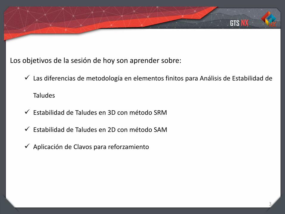
Los objetivos de la sesión de hoy son aprender sobre:
✓ Las diferencias de metodología en elementos finitos para Análisis de Estabilidad de
Taludes
✓ Estabilidad de Taludes en 3D con método SRM
✓ Estabilidad de Taludes en 2D con método SAM
✓ Aplicación de Clavos para reforzamiento

Integrated Solver Optimized for the next generation 64-bit platform
Finite Element Solutions for Geotechnical Engineering
Contents
Parte 1. Objetivos
Parte 2. Introducción
Parte 3. Estabilidad de Taludes en 2D
Parte 4. Estabilidad de Taludes en 3D
Parte 5. Conclusión

GTS NX
5
La estabilidad del talud de un terraplén o una excavación
es uno de los problemas mas frecuentes en la ingeniería
geotécnica. Recientemente se hizo posible para el análisis
numérico simular geometrías destruidas y reflejar la
condición del sitio real.
Introducción
El talud siempre cuenta con peso propio pero si fuerzas externas, tales como presión
de poro, cargas aplicadas, terremotos, etc actúan sobre tal, su estabilidad se vera
muy afectada. Una falla del talud (desprendimiento) puede ocurrir si la tensión
cortante interna debida al peso propio y las fuerzas externas son mayor que la
resistencia al corte del suelo.
GTS NX
6
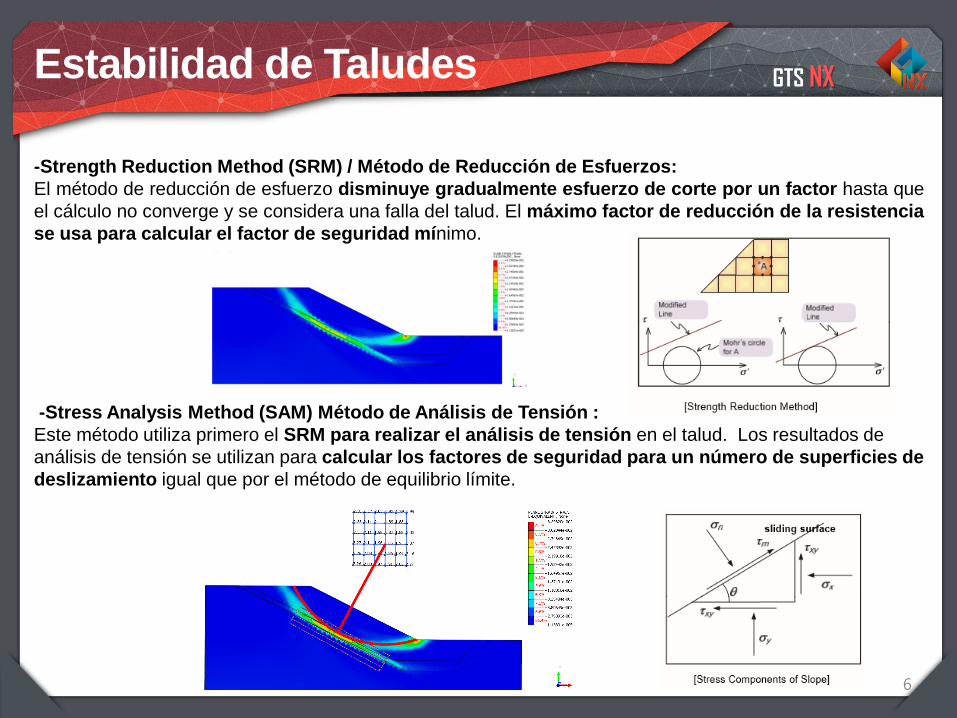
-Strength Reduction Method (SRM) / Método de Reducción de Esfuerzos:
El método de reducción de esfuerzo disminuye gradualmente esfuerzo de corte por un factor hasta que
el cálculo no converge y se considera una falla del talud. El máximo factor de reducción de la resistencia
se usa para calcular el factor de seguridad mínimo.
-Stress Analysis Method (SAM) Método de Análisis de Tensión :
Este método utiliza primero el SRM para realizar el análisis de tensión en el talud. Los resultados de
análisis de tensión se utilizan para calcular los factores de seguridad para un número de superficies de
deslizamiento igual que por el método de equilibrio límite.
Estabilidad de Taludes

GTS NX
7
Reforzamiento por Clavo de Suelo
El clavo de suelo es un tipo de reforzamiento que se inserta desde la superficie de la
pendiente sin ningún pretensado. Se aumenta la fuerza de cizallamiento total de la suelo
original, se controlan los desplazamientos del suelo y se instala el refuerzo desde arriba
hacia abajo.
El grado de seguridad aportado por un solo clavo es generalmente bajo para toda la
estabilidad.
Los clavos de suelo son eficaz para reforzar un corte de pendiente donde se espera una
superficie de falla deslizante superficial, para reforzar excavaciones temporales y paredes
permanentes.
Se pueden clasificar tres tipos de clavado en el suelo:
1. Tipo de gravedad en el que se inserta el refuerzo de clavos en los orificios taladrados y
se ensambla sin presión
2. Tipo de presión en el que se sella la pieza de anclaje de clavos utilizando un
empaquetador permanente y son sellados a presión (grouted).
3. La combinación del tipo de presión con los empacadores de goma reutilizables en la
primera etapa y el tipo de gravedad en la segunda etapa
GTS NX
8
Reforzamiento por Clavo de Suelo
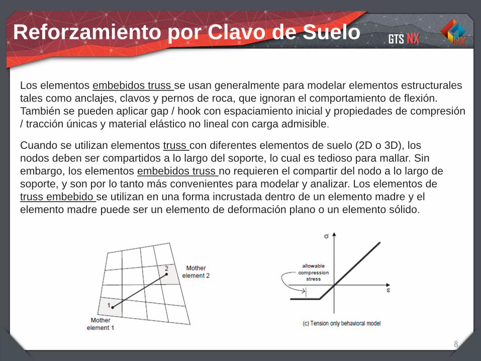
Los elementos embebidos truss se usan generalmente para modelar elementos estructurales
tales como anclajes, clavos y pernos de roca, que ignoran el comportamiento de flexión.
También se pueden aplicar gap / hook con espaciamiento inicial y propiedades de compresión
/ tracción únicas y material elástico no lineal con carga admisible.
Cuando se utilizan elementos truss con diferentes elementos de suelo (2D o 3D), los
nodos deben ser compartidos a lo largo del soporte, lo cual es tedioso para mallar. Sin
embargo, los elementos embebidos truss no requieren el compartir del nodo a lo largo de
soporte, y son por lo tanto más convenientes para modelar y analizar. Los elementos de
truss embebido se utilizan en una forma incrustada dentro de un elemento madre y el
elemento madre puede ser un elemento de deformación plano o un elemento sólido.

Integrated Solver Optimized for the next generation 64-bit platform
Finite Element Solutions for Geotechnical Engineering
Contents
Parte 1. Objetivos
Parte 2. Introducción
Parte 3. Estabilidad de Taludes en 2D
Parte 4. Estabilidad de Taludes en 3D
Parte 5. Conclusión
Integrated Solver Optimized for the next generation 64-bit platform
Finite Element Solutions for Geotechnical Engineering
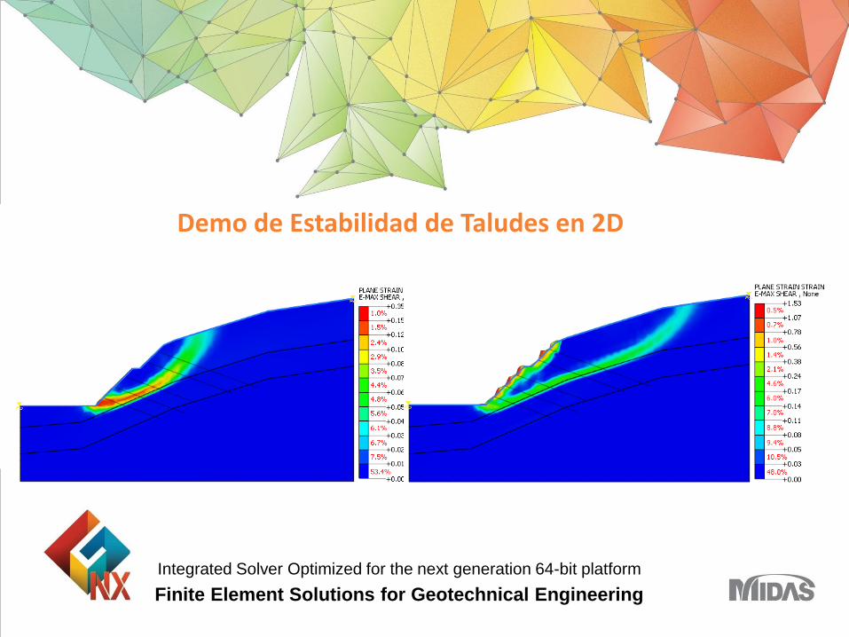
Demo de Estabilidad de Taludes en 2D

GTS NX
11
Geometry Import
Import Materials
Mesh generation
Boundary Conditions
STEP 01
STEP 02
STEP 03
STEP 04
STEP 05 Perform analysis and check result
Overview
GTS NX
Overview
1-12
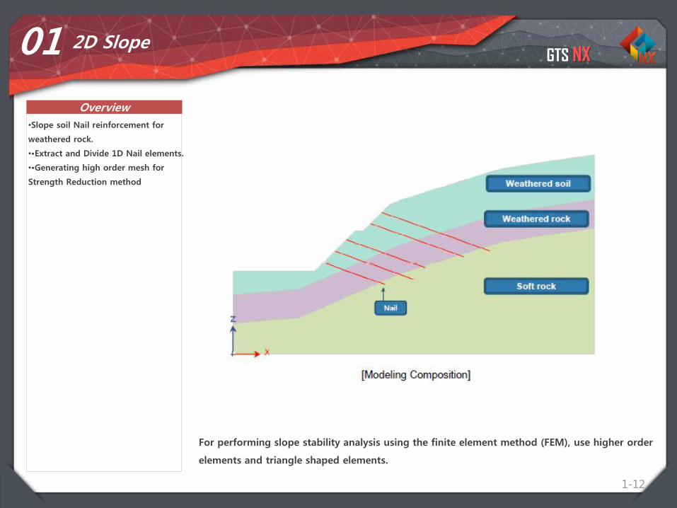
01 2D Slope
•Slope soil Nail reinforcement for
weathered rock.
••Extract and Divide 1D Nail elements.
••Generating high order mesh for
Strength Reduction method
For performing slope stability analysis using the finite element method (FEM), use higher order
elements and triangle shaped elements.
GTS NX
1-13
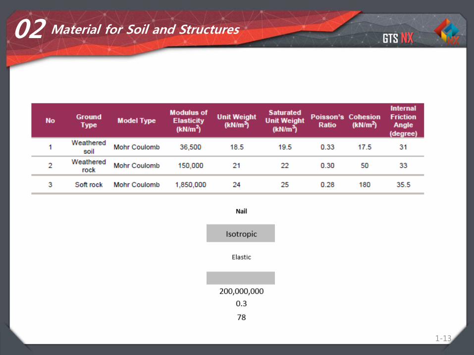
02 Material for Soil and Structures
GTS NX
1-14
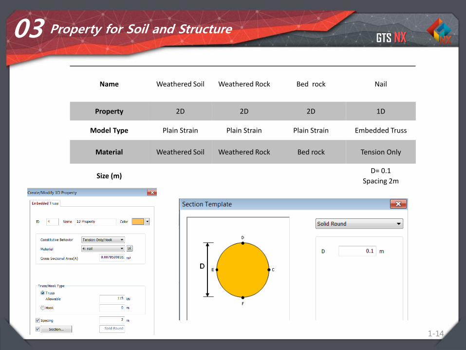
03 Property for Soil and Structure
Name Weathered Soil Weathered Rock Bed rock Nail
Property 2D 2D 2D 1D
Model Type Plain Strain Plain Strain Plain Strain Embedded Truss
Material Weathered Soil Weathered Rock Bed rock Tension Only
Size (m)D= 0.1
Spacing 2m
GTS NX
Procedure
1-15
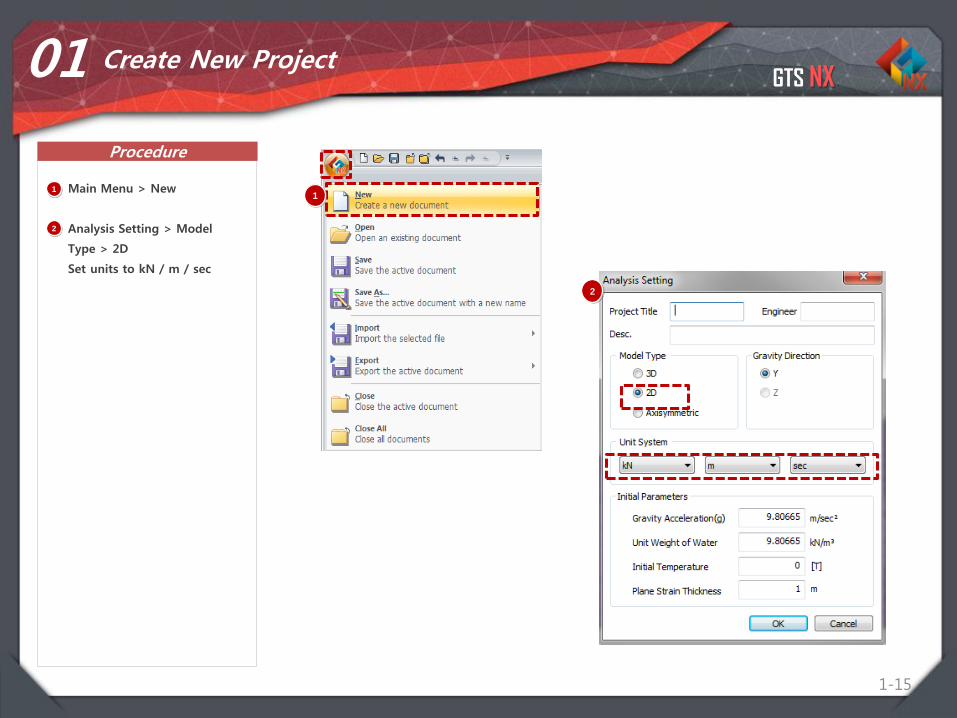
01 Create New Project
11
Main Menu > New
Analysis Setting > Model
Type > 2D
Set units to kN / m / sec
2
2
GTS NX
Procedure
1-16
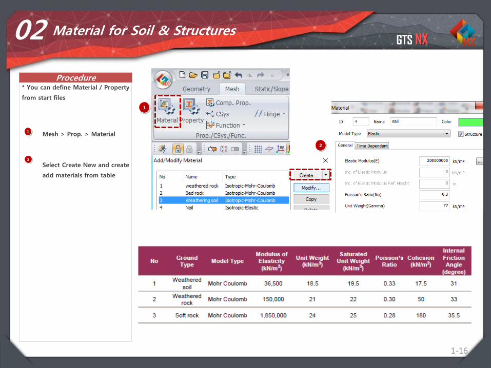
02 Material for Soil & Structures
1Mesh > Prop. > Material
Select Create New and create
add materials from table
* You can define Material / Property
from start files
2
1
2
GTS NX
Procedure
1-17
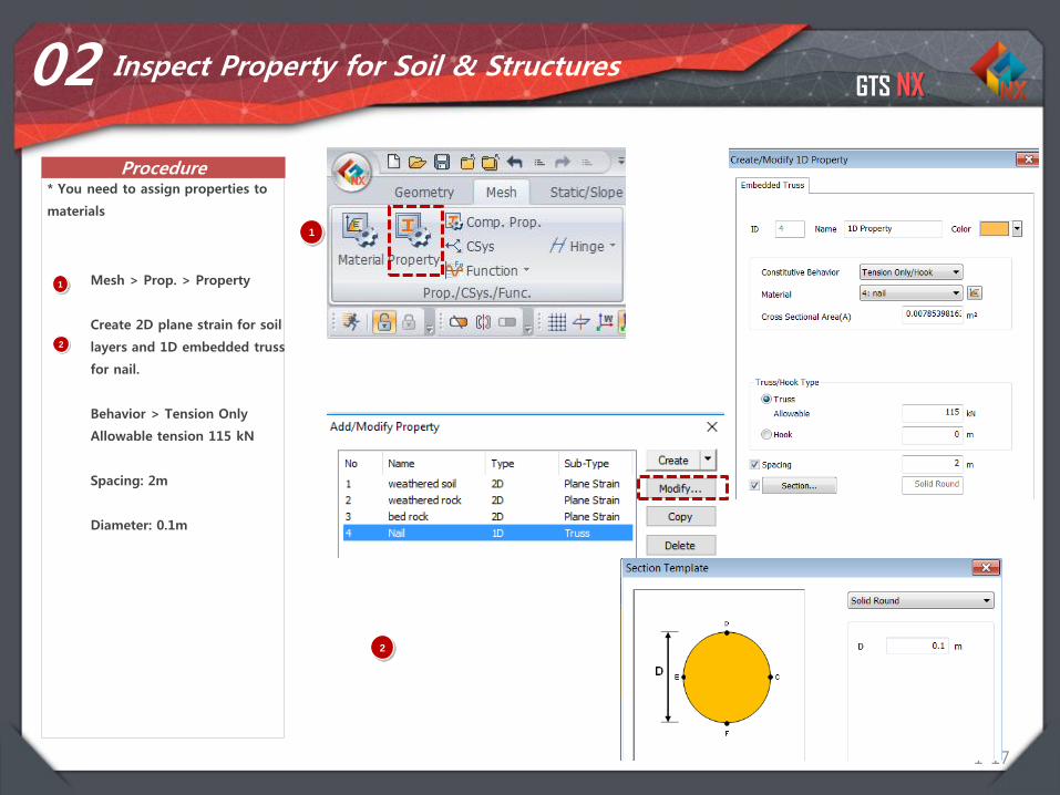
02 Inspect Property for Soil & Structures
1 Mesh > Prop. > Property
Create 2D plane strain for soil
layers and 1D embedded truss
for nail.
Behavior > Tension Only
Allowable tension 115 kN
Spacing: 2m
Diameter: 0.1m
* You need to assign properties to
materials
2
1
2

GTS NX
Procedure
1-18
03 Import Geometry
1 Main Menu > Import > DWG
Select Soil Nail Reinforced
Slope Stability DWG file
* Import CAD file to start modeling
2
1
2

GTS NX
Procedure
1-19
04 Generate Mesh (2D Element)
1 Mesh > Generate > 2D > Auto -
Area
Select Edge(s) > Select edges
for “Soil layer” as highlighted in
the figure. (Don’t include nails)
Input element Size : 1
(1m between two nodes)
Select Property : weathered soil
Input Mesh Set Name : soil
Click on the >> icon to open
the Advanced Option Window
Activate Higher Order Elements
Click OK , then Click Apply
Repeat for other layers ,
increase sizes to 1m and 2m.
2
3
4
5
6
1
7
8
3
4
7
6

GTS NX
Procedure
1-20
04 Generate Mesh (Mesh 1D Element)
1
Mesh > Generate > 1D
Element
Select the TYPE: Edge(s) >
Select 5 edges for “nails” as
highlighted in the figure.
Size Method > Division: 1
Select Property : Nail
Input Mesh Set Name : Nails
Click OK
1
2
3
4
5
2
3
4
2
GTS NX
Procedure
1-21
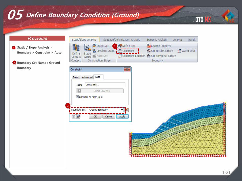
05 Define Boundary Condition (Ground)
1 Static / Slope Analysis >
Boundary > Constraint > Auto
Boundary Set Name : Ground
Boundary
1
2
2
GTS NX
Procedure
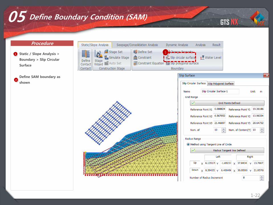
1-22
05 Define Boundary Condition (SAM)
1 Static / Slope Analysis >
Boundary > Slip Circular
Surface
Define SAM boundary as
shown
1
2
2

GTS NX
Procedure
1-23
06 Load Condition (Self Weight)
1
1 Static / Slope Analysis >
Load > Self Weight
Load Set Name : S/W2
2
GTS NX
Procedure
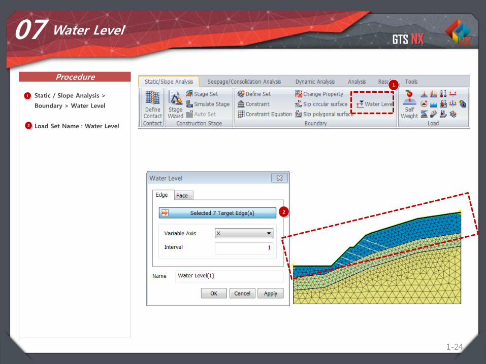
1-24
07 Water Level
1
1 Static / Slope Analysis >
Boundary > Water Level
Load Set Name : Water Level2
2

GTS NX
Procedure
1-25
08 Define SRM Analysis Case
1 Analysis > General
Solution Type > Slope Stability
SRM > SRM with Nails
Activate all except SAM BC
Activate Options in Output
Control as shown
2
1
2
3
Drag & Drop
3
4
5
GTS NX
Procedure
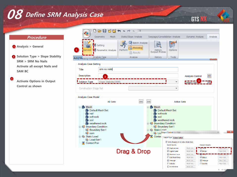
1-26
08 Define SRM Analysis Case
1 Analysis > General
Solution Type > Slope Stability
SRM > SRM No Nails
Activate all except Nails and
SAM BC
Activate Options in Output
Control as shown
2
1
2
3
Drag & Drop
3
4
5

GTS NX
Procedure
1-27
09 Define SAM Analysis Case
1 Analysis > General
Solution Type > Slope Stability
SAM > SAM with nails
Activate all
Activate Options in Output
Control as shown
2
1
2
3
Drag & Drop
3
4
5
GTS NX
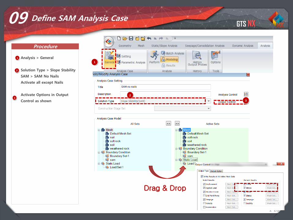
Procedure
1-28
09 Define SAM Analysis Case
1 Analysis > General
Solution Type > Slope Stability
SAM > SAM No Nails
Activate all except Nails
Activate Options in Output
Control as shown
2
1
2
3
Drag & Drop
3
4
5
GTS NX
Procedure
1-29
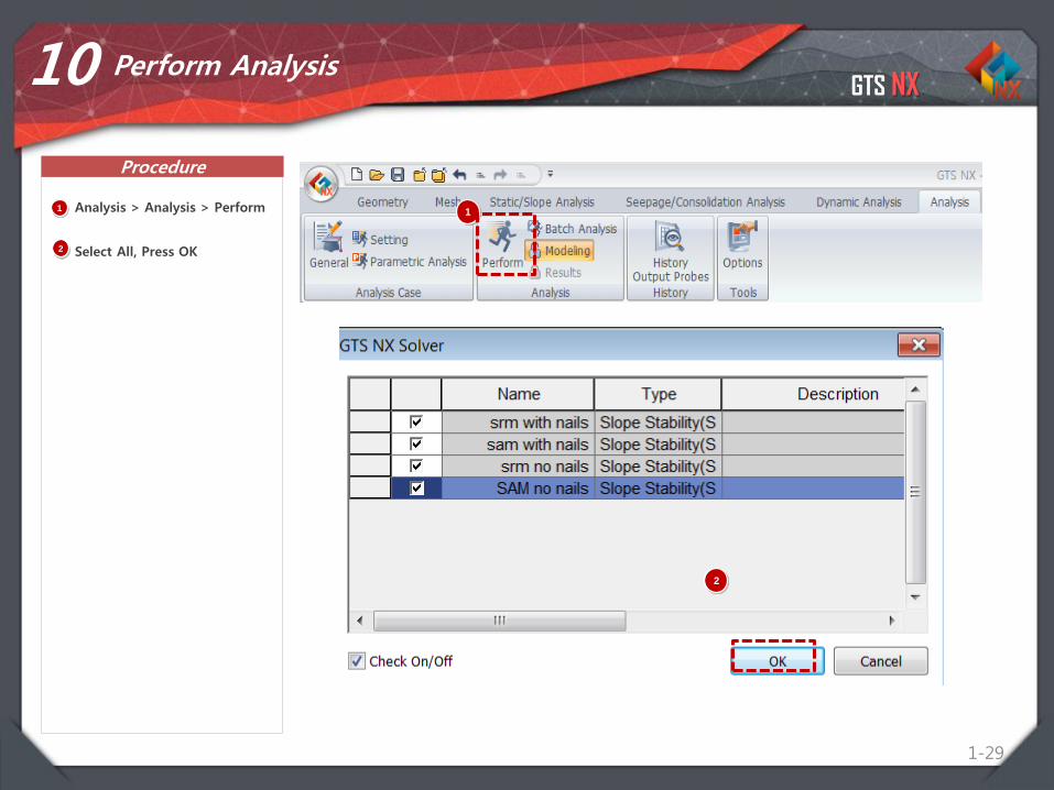
10 Perform Analysis
1 Analysis > Analysis > Perform
Select All, Press OK
1
2
2
GTS NX
Procedure
1-30
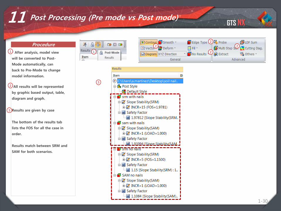
11 Post Processing (Pre mode vs Post mode)
* After analysis, model view
will be converted to Post-
Mode automatically, can
back to Pre-Mode to change
model information.
1 1
*All results will be represented
by graphic based output, table,
diagram and graph.
Results are given by case
The bottom of the results tab
lists the FOS for all the case in
order.
Results match between SRM and
SAM for both scenarios.
2
2
2
22
3
3
GTS NX
Procedure
31
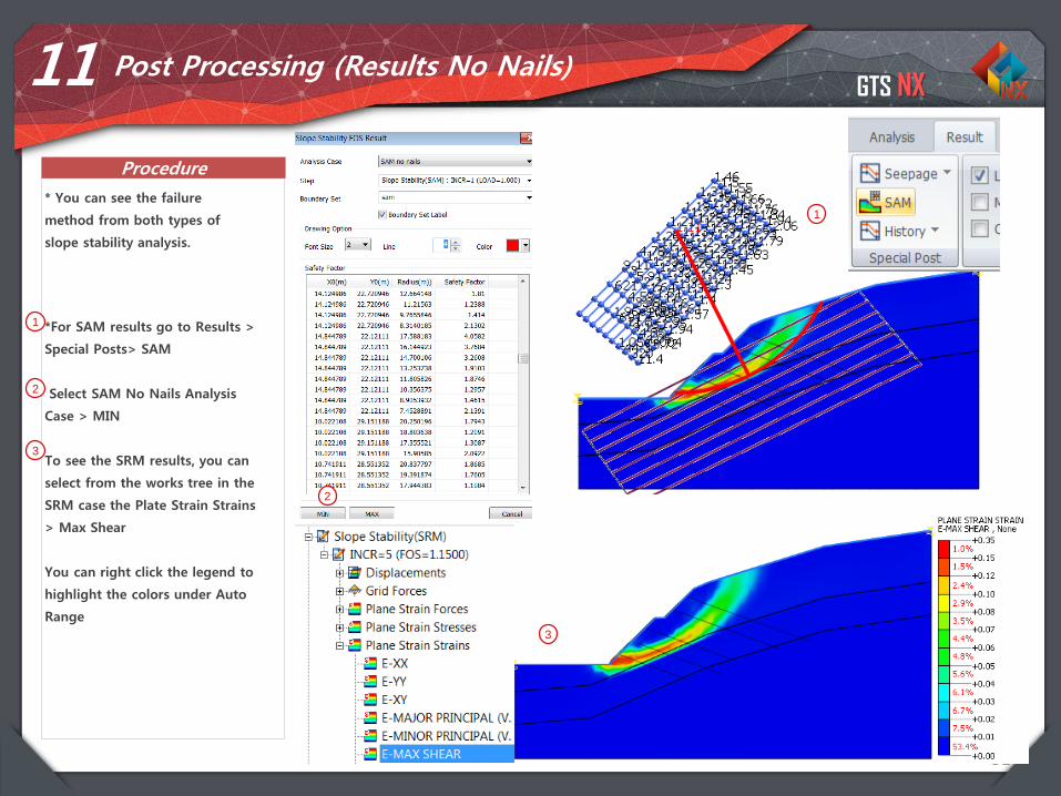
11 Post Processing (Results No Nails)
* You can see the failure
method from both types of
slope stability analysis.
1
1 *For SAM results go to Results >
Special Posts> SAM
Select SAM No Nails Analysis
Case > MIN
To see the SRM results, you can
select from the works tree in the
SRM case the Plate Strain Strains
> Max Shear
You can right click the legend to
highlight the colors under Auto
Range
2
3
2
3
GTS NX
Procedure
32
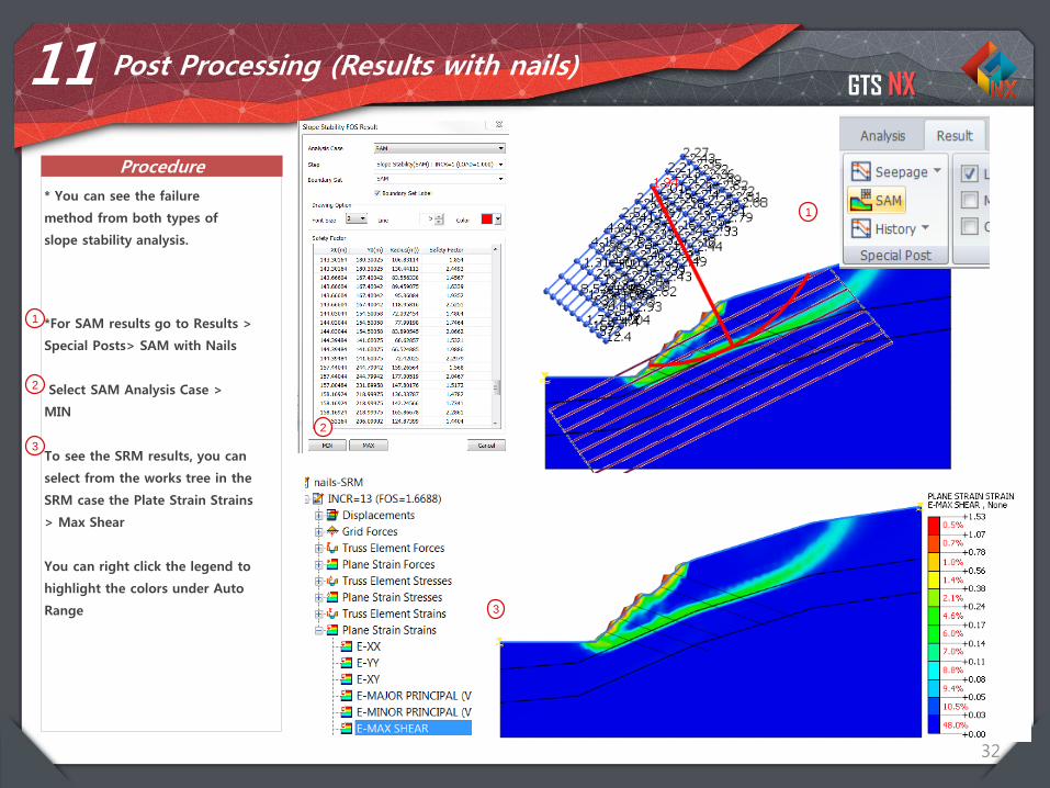
11 Post Processing (Results with nails)
* You can see the failure
method from both types of
slope stability analysis.
1
1 *For SAM results go to Results >
Special Posts> SAM with Nails
Select SAM Analysis Case >
MIN
To see the SRM results, you can
select from the works tree in the
SRM case the Plate Strain Strains
> Max Shear
You can right click the legend to
highlight the colors under Auto
Range
2
3
2
3
GTS NX
Procedure
33
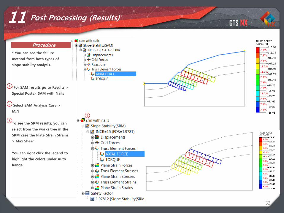
11 Post Processing (Results)
* You can see the failure
method from both types of
slope stability analysis.
1
1 *For SAM results go to Results >
Special Posts> SAM with Nails
Select SAM Analysis Case >
MIN
To see the SRM results, you can
select from the works tree in the
SRM case the Plate Strain Strains
> Max Shear
You can right click the legend to
highlight the colors under Auto
Range
2
3
2
3
Integrated Solver Optimized for the next generation 64-bit platform
Finite Element Solutions for Geotechnical Engineering
Contents
Parte 1. Objetivos
Parte 2. Introducción
Parte 3. Estabilidad de Taludes en 2D
Parte 4. Estabilidad de Taludes en 3D
Parte 5. Conclusión
GTS NX
35
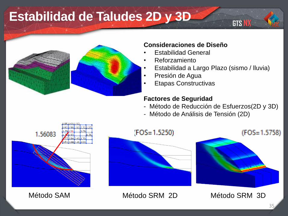
Estabilidad de Taludes 2D y 3D
Consideraciones de Diseño
• Estabilidad General
• Reforzamiento
• Estabilidad a Largo Plazo (sismo / lluvia)
• Presión de Agua
• Etapas Constructivas
Factores de Seguridad
- Método de Reducción de Esfuerzos(2D y 3D)
- Método de Análisis de Tensión (2D)
Método SRM 2DMétodo SAM Método SRM 3D

GTS NX
36
Estabilidad de Taludes en 3D con Método SRM
Sliced Planes Iso Surface
Integrated Solver Optimized for the next generation 64-bit platform
Finite Element Solutions for Geotechnical Engineering
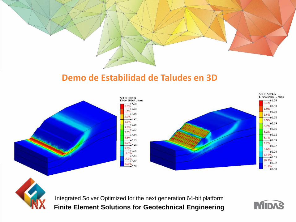
Demo de Estabilidad de Taludes en 3D

GTS NX
38
Geometry Import
Import Materials
Mesh generation
Boundary Conditions
STEP 01
STEP 02
STEP 03
STEP 04
STEP 05 Perform analysis and check result
Overview
GTS NX
1-39
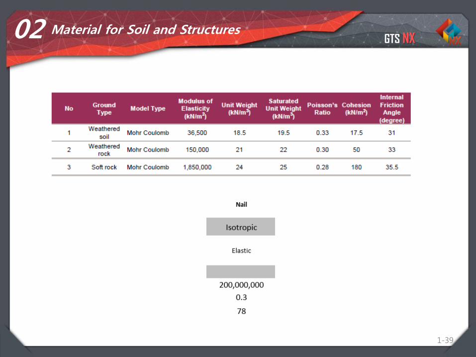
02 Material for Soil and Structures

GTS NX
1-40
03 Property for Soil and Structure
Name Weathered Soil Weathered Rock Bed rock Nail
Property 3D 3D 3D 3D
Model Type Solid Solid Solid Embedded Truss
Material Weathered Soil Weathered Rock Bed rock Nail (Steel)
Size (m) D= 0.1

GTS NX
Overview
1-41
01 Open Project
11
Main Menu > Open
3D Slope Nail Start File
2
2

GTS NX
Procedure
1-42
03
1
1
Geometry >Protrude > Extrude
Select 3 faces
Direction: Y
Enter 30 m
Click Preview, Click OK
2
3
2
Geometry works
3

GTS NX
Procedure
1-43
03
1
1
Geometry > Transform >
Translate > Copy
Target: 5 nail curves
Select Y axis
Copy > Distance 2 > Times 16
Apply
2
3
4
Geometry works
3
42
4

GTS NX
Procedure
1-44
03
1
1
Geometry > Surface Solid >
Imprint > Auto
Target: 3 solids
Tool: all nails except edges
Apply
2
3
4
Geometry works
3
4
2
GTS NX
Procedure
1-45
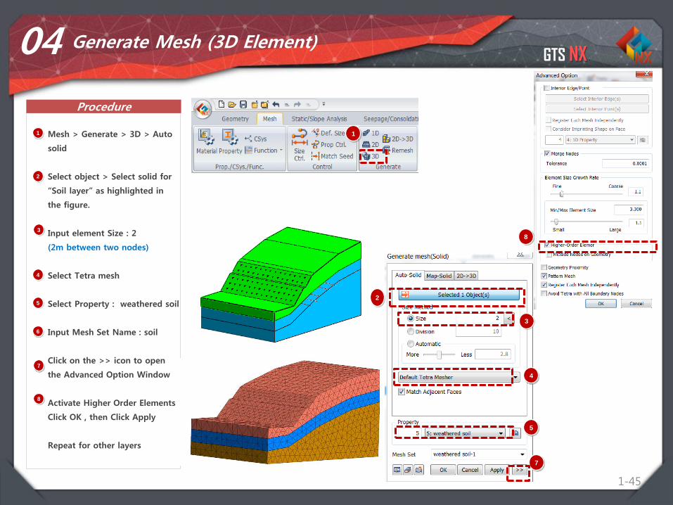
04 Generate Mesh (3D Element)
1 Mesh > Generate > 3D > Auto
solid
Select object > Select solid for
“Soil layer” as highlighted in
the figure.
Input element Size : 2
(2m between two nodes)
Select Tetra mesh
Select Property : weathered soil
Input Mesh Set Name : soil
Click on the >> icon to open
the Advanced Option Window
Activate Higher Order Elements
Click OK , then Click Apply
Repeat for other layers
2
3
4
5
6
1
7
8
3
4
7
8
2
5
GTS NX
Procedure
1-46
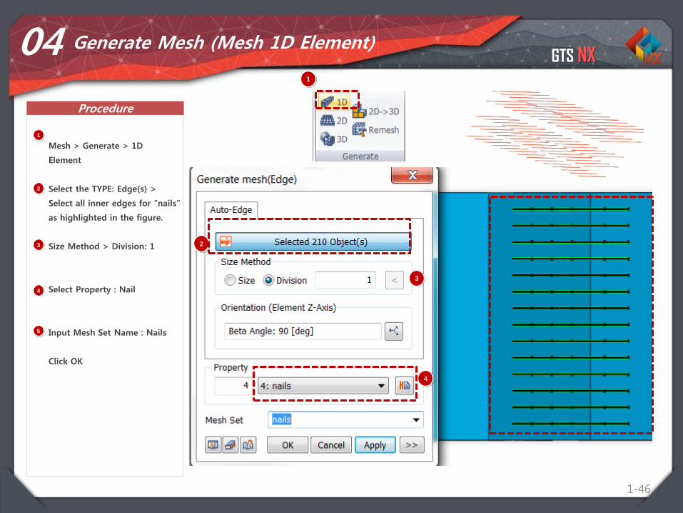
04 Generate Mesh (Mesh 1D Element)
1
Mesh > Generate > 1D
Element
Select the TYPE: Edge(s) >
Select all inner edges for “nails”
as highlighted in the figure.
Size Method > Division: 1
Select Property : Nail
Input Mesh Set Name : Nails
Click OK
1
2
3
4
5
2
3
4
GTS NX
Procedure
1-47
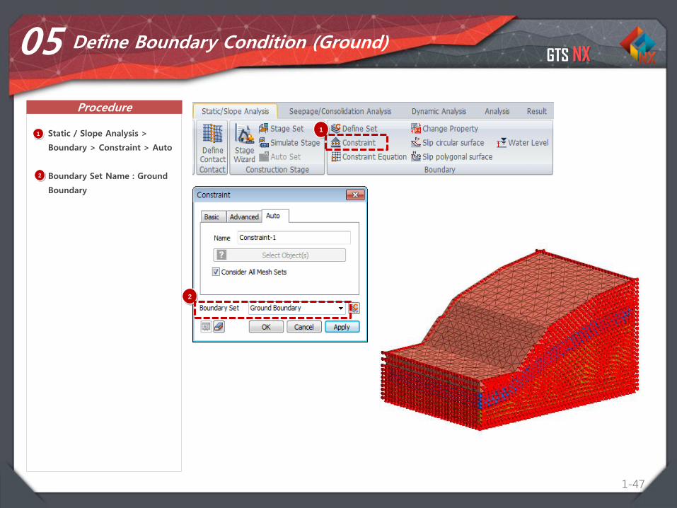
05 Define Boundary Condition (Ground)
1 Static / Slope Analysis >
Boundary > Constraint > Auto
Boundary Set Name : Ground
Boundary
1
2
2

GTS NX
Procedure
1-48
06 Water Level
1 Static / Slope Analysis >
Boundary > Water Level
Select top faces of geometry
Press Apply
1
2
2
GTS NX
Procedure
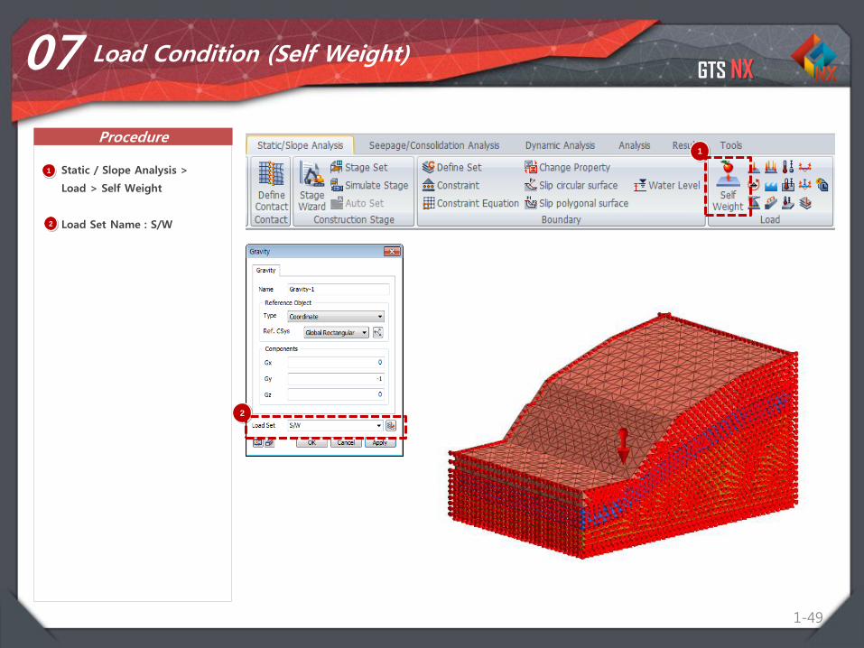
1-49
07 Load Condition (Self Weight)
1
1 Static / Slope Analysis >
Load > Self Weight
Load Set Name : S/W2
2
GTS NX
Procedure
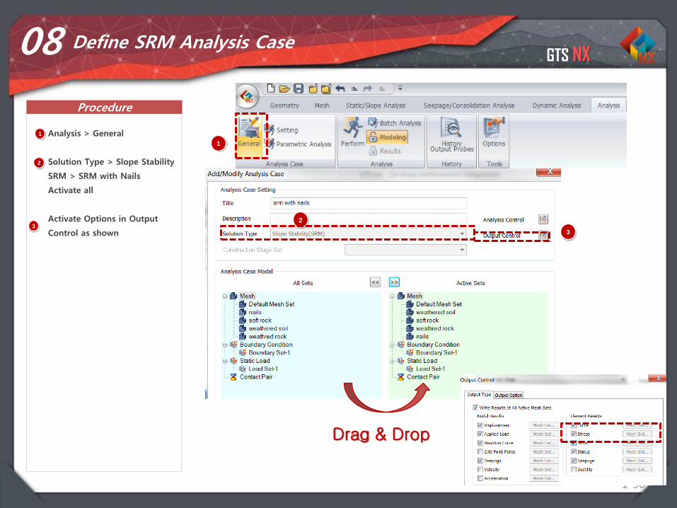
1-50
08 Define SRM Analysis Case
1 Analysis > General
Solution Type > Slope Stability
SRM > SRM with Nails
Activate all
Activate Options in Output
Control as shown
2
1
2
3
Drag & Drop
3
4
5

GTS NX
Procedure
1-51
09 Define SRM Analysis Case
1 Analysis > General
Solution Type > Slope Stability
SRM > SRM No Nails
Activate all except Nails
Activate Options in Output
Control as shown
2
1
2
3
Drag & Drop
3
4
5

GTS NX
Procedure
1-52
10 Perform Analysis
1 Analysis > Analysis > Perform
Select All, Press OK
1
2
2
GTS NX
Procedure
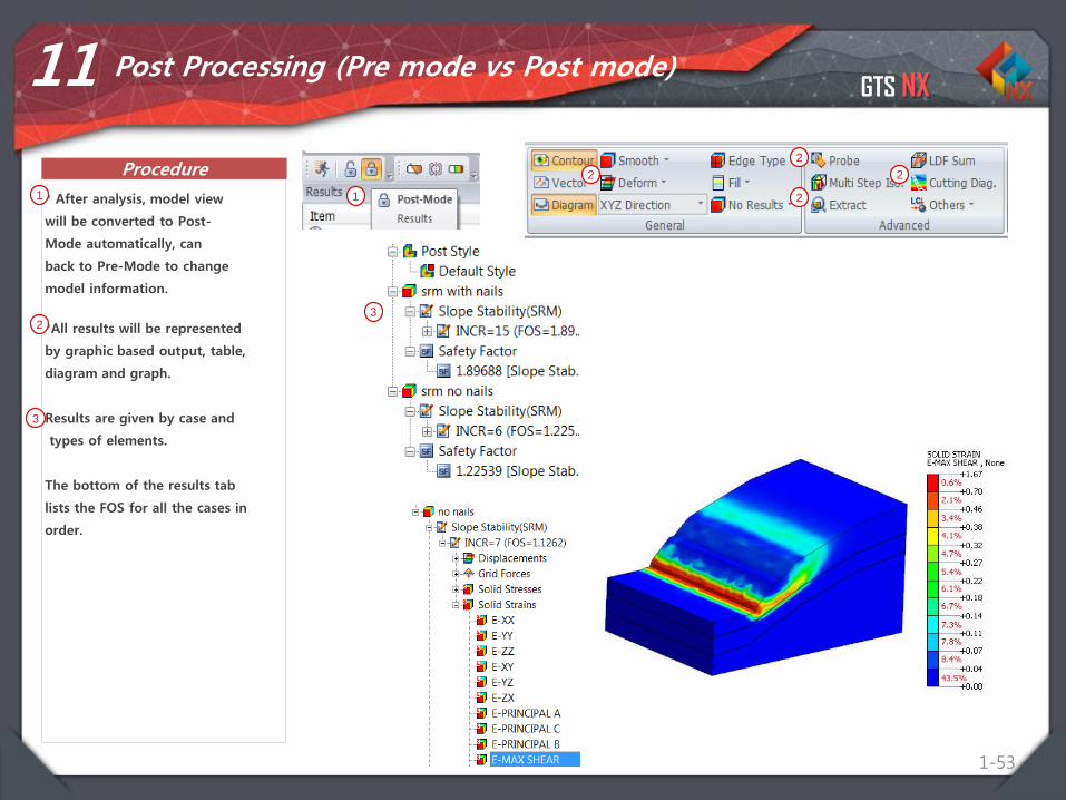
1-53
11 Post Processing (Pre mode vs Post mode)
* After analysis, model view
will be converted to Post-
Mode automatically, can
back to Pre-Mode to change
model information.
1 1
*All results will be represented
by graphic based output, table,
diagram and graph.
Results are given by case and
types of elements.
The bottom of the results tab
lists the FOS for all the cases in
order.
2
2
2
22
3
3

GTS NX
Procedure
1-54
11 Post Processing (Pre mode vs Post mode)
*Inspect Forces on anchors
SRM > Truss Element
Forces > Axial Force
*Inspect Failure Surface
SRM > Solid Strains > Max
Shear
1 1
*2
2
2
22
3
Integrated Solver Optimized for the next generation 64-bit platform
Finite Element Solutions for Geotechnical Engineering
Contents
Parte 1. Objetivos
Parte 2. Introducción
Parte 3. Estabilidad de Taludes
Parte 4. Estabilidad de Taludes
Parte 5. Conclusión
GTS NX
56
• Midas GTS NX tiene capacidades para analizar la estabilidad de taludes utilizando
diferentes métodos dependiendo de las dimensiones y preferencias.
• Los principales beneficios de la SRM y SAM son que no requiere conocimiento previo del
rango, da resultados óptimos, y mayor seguridad en los resultados.
• Midas GTS NX tiene elementos embebidos truss que permiten el fácil reforzamiento de
suelo sin tener que lidiar con la conexión de nodos a lo largo del reforzamiento.
• Gráficos de contorno permiten una verificación rápida y gráficas ayudan en la extracción
de información detallada para el área de interés.
• Los resultados obtenidos de la simulación 3D correcta da confianza para los ingenieros
geotécnicos y resulta en diseño óptimo por el ingeniero estructural.
Conclusión

Integrated Solver Optimized for the next generation 64-bit platform
Finite Element Solutions for Geotechnical Engineering
Preguntas?http://latinamerica.midasuser.com/web/