EST3 Life Safety Control Platform - · PDF fileEST3 Network Analogue Fire Alarm and Security...
32
Submittal Guide Analogue Fire Alarm and Security Solutions EST3 Life Safety Control Platform
Transcript of EST3 Life Safety Control Platform - · PDF fileEST3 Network Analogue Fire Alarm and Security...

Submittal Guide
Analogue Fire Alarm and Security Solutions
EST3 Life Safety Control Platform


Project: _________________________
Contact: _________________________
Date: _________________________
It is with great pleasure that we provide this submittal for an EST3 Life
Safety Control Platform. This guide includes a comprehensive
presentation of control panels and related system components. Products
we are submitting for your consideration are indicated by a checkmark
in the margins of the pages that follow.
For information on field devices that we are submitting for your
consideration, please see the accompanying guide (part number
85010-0138).
More detailed information can be found in individual catalogue sheets
dedicated to each product. All these sheets, along with guide
specifications and other useful product information, are available
electronically on our LifeLines CD-ROM. This comprehensive collection
of life safety related literature is fully searchable and includes a utility for
printing multiple catalogue sheets.
Thank you for giving us the opportunity to provide this submittal. Please
do not hesitate to contact us should you require further information.
____________________________

EDWARDS SYSTEMS TECHNOLOGY
Submittal Guide: EST3 Life Safety and Security SolutionsPart Number: 85010-0136
© 2003 EST International
Headquar tersHeadquar tersHeadquar tersHeadquar tersHeadquar ters201 City Centre Dr., Ste 500, Mississauga, On L5B 2T4 CANADA;
Phone: (001) 905-270-1711; Fax: (001) 905-270-9553;Web: www.estinternational.com
E-mail: [email protected]
EuropeEuropeEuropeEuropeEuropeRudford Estate, Ford Aerodrome, Arundel BN18 0BE, UK;
Phone: +44-1903-711 440; Fax:+44-1903-711 448Web: www.estinternational.com
Also from EST International...Also from EST International...Also from EST International...Also from EST International...Also from EST International...Submittal Guide: QuickStart Life Safety System; P/N 85010-0137
Submittal Guide: Field Devices; P/N 85010-0138
It is our intention to keep the product information current and accurate. We can not coverspecific applications or anticipate all requirements. All specifications are subject to change
without notice. For more information or questions relative to this submittal guide,contact EST International.
Contents
Display 8Liquid Crystal Display Module .................................................... 8Control Display Modules ............................................................. 8FireWorks™ ............................................................................... 9FireWorks Options .................................................................... 10Video Display Utility for Text Annunciation ................................ 10
Remote Repeaters (annunciators) 11Remote Repeaters ................................................................... 11Remote Repeater Cabinets ...................................................... 11Envoy Graphic Repeater ........................................................... 12
Audio 13Audio Amplifiers (Zoned) ......................................................... 14Audio Amplifiers (Banked) ....................................................... 14Remote Microphones ............................................................... 14
Security, Access Control 15Security/Access Control Module .............................................. 15Keypad/Display ........................................................................ 15Card Reader Controller ............................................................. 16Proximity Card Readers ............................................................ 17Proximity Card Readers ............................................................ 17Proximity Access Cards ........................................................... 18Key Fob Proximity Access Credential ....................................... 18Proximity Tag Access Credential .............................................. 18
Accessories 19Cabinets ................................................................................... 19Main Panel Power Supplies ...................................................... 20Power Supplies ........................................................................ 21Remote Diagnostic Utility ......................................................... 22RS-232 Optical Isolator Card .................................................... 23CDR-3 Coder ............................................................................ 23MTM March Time Module ........................................................ 23Network Short Haul Modem ..................................................... 23Ground Fault Detection Module ................................................ 24Alphanumeric Pager Interface .................................................. 24
Local Rail Modules 4Central Processor Unit ............................................................... 3Network Communication Card .................................................... 3RS-232 Communication Card ..................................................... 3Signature Driver Controller Modules ........................................... 4Addressable Analogue Device Controller .................................... 5Modem Communicator ............................................................... 7 DISPLAY
LOCAL RAIL MODULESREMOTE REPEATERS
AUDIOSECURITY/ACCESS
ACCESSORIES
Marketplace IdentifiersIn order to make this submittalguide as easy to use as possible,product entries and descriptions arecolour-coded to indicate the marketfor which the product is best suited.Market Identifiers are colour-codedas follows:
UL
EN54
Universal (i.e. suitable forboth UL and EN54 markets)
For listing and aproval status ofindividual products, consult theliterature sheet referenced adjacentto each product entry.
EST3 NetworkAnalogue Fire Alarm and Security Solutions

EST3 NetworkAnalogue Fire Alarm and Security Solutions
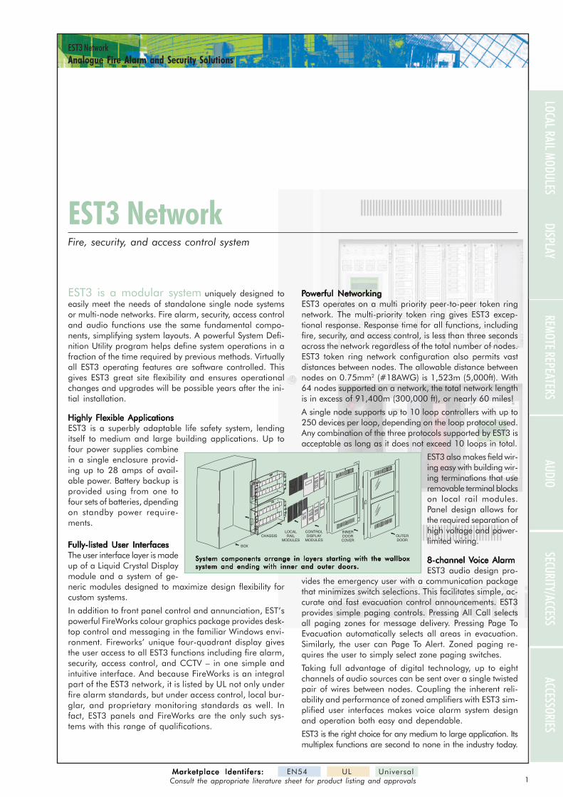
EST3 is a modular system uniquely designed toeasily meet the needs of standalone single node systemsor multi-node networks. Fire alarm, security, access controland audio functions use the same fundamental compo-nents, simplifying system layouts. A powerful System Defi-nition Utility program helps define system operations in afraction of the time required by previous methods. Virtuallyall EST3 operating features are software controlled. Thisgives EST3 great site flexibility and ensures operationalchanges and upgrades will be possible years after the ini-tial installation.
Highly Flexible ApplicationsHighly Flexible ApplicationsHighly Flexible ApplicationsHighly Flexible ApplicationsHighly Flexible ApplicationsEST3 is a superbly adaptable life safety system, lendingitself to medium and large building applications. Up tofour power supplies combinein a single enclosure provid-ing up to 28 amps of avail-able power. Battery backup isprovided using from one tofour sets of batteries, dpendingon standby power require-ments.
Fully-listed User InterfacesFully-listed User InterfacesFully-listed User InterfacesFully-listed User InterfacesFully-listed User InterfacesThe user interface layer is madeup of a Liquid Crystal Displaymodule and a system of ge-neric modules designed to maximize design flexibility forcustom systems.
In addition to front panel control and annunciation, EST’spowerful FireWorks colour graphics package provides desk-top control and messaging in the familiar Windows envi-ronment. Fireworks’ unique four-quadrant display givesthe user access to all EST3 functions including fire alarm,security, access control, and CCTV – in one simple andintuitive interface. And because FireWorks is an integralpart of the EST3 network, it is listed by UL not only underfire alarm standards, but under access control, local bur-glar, and proprietary monitoring standards as well. Infact, EST3 panels and FireWorks are the only such sys-tems with this range of qualifications.
PPPPPowerful Networkingowerful Networkingowerful Networkingowerful Networkingowerful NetworkingEST3 operates on a multi priority peer-to-peer token ringnetwork. The multi-priority token ring gives EST3 excep-tional response. Response time for all functions, includingfire, security, and access control, is less than three secondsacross the network regardless of the total number of nodes.EST3 token ring network configuration also permits vastdistances between nodes. The allowable distance betweennodes on 0.75mm2 (#18AWG) is 1,523m (5,000ft). With64 nodes supported on a network, the total network lengthis in excess of 91,400m (300,000 ft), or nearly 60 miles!
A single node supports up to 10 loop controllers with up to250 devices per loop, depending on the loop protocol used.Any combination of the three protocols supported by EST3 isacceptable as long as it does not exceed 10 loops in total.
EST3 also makes field wir-ing easy with building wir-ing terminations that useremovable terminal blockson local rail modules.Panel design allows forthe required separation ofhigh voltage and power-limited wiring.
8-8-8-8-8-channel Vchannel Vchannel Vchannel Vchannel Voice Alarmoice Alarmoice Alarmoice Alarmoice AlarmEST3 audio design pro-
vides the emergency user with a communication packagethat minimizes switch selections. This facilitates simple, ac-curate and fast evacuation control announcements. EST3provides simple paging controls. Pressing All Call selectsall paging zones for message delivery. Pressing Page ToEvacuation automatically selects all areas in evacuation.Similarly, the user can Page To Alert. Zoned paging re-quires the user to simply select zone paging switches.
Taking full advantage of digital technology, up to eightchannels of audio sources can be sent over a single twistedpair of wires between nodes. Coupling the inherent reli-ability and performance of zoned amplifiers with EST3 sim-plified user interfaces makes voice alarm system designand operation both easy and dependable.
EST3 is the right choice for any medium to large application. Itsmultiplex functions are second to none in the industry today.
EST3 NetworkEST3 Network
BOX
LOCALRAIL
MODULESCHASSIS
CONTROLDISPLAY
MODULES
INNERDOORCOVER
OUTERDOOR
System components arrange in layers starting with the wallboxSystem components arrange in layers starting with the wallboxSystem components arrange in layers starting with the wallboxSystem components arrange in layers starting with the wallboxSystem components arrange in layers starting with the wallboxsystem and ending with inner and outer doors.system and ending with inner and outer doors.system and ending with inner and outer doors.system and ending with inner and outer doors.system and ending with inner and outer doors.
Fire, security, and access control system
1
DISPLAYLOCAL RAIL MODULES
REMOTE REPEATERSAUDIO
SECURITY/ACCESSACCESSORIES
Marketplace Identifers:Marketplace Identifers:Marketplace Identifers:Marketplace Identifers:Marketplace Identifers: EN54 UL UniversalConsult the appropriate literature sheet for product listing and approvals
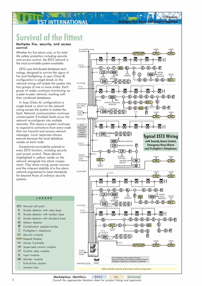
Survival of the fittestSurvival of the fittest
Typical EST3 Wiringwith Security, Access Control,
Emergency Voice/Alarmand Firefighter's Telephones
Multiplex fire, securityMultiplex fire, securityMultiplex fire, securityMultiplex fire, securityMultiplex fire, security, and access, and access, and access, and access, and accesscontrolcontrolcontrolcontrolcontrol
Whether for fire alarm only, or for totallife safety protection including securityand access control, the EST3 network isthe most survivable system available.
EST3 uses distributed database tech-nology, designed to survive the rigors offire and firefighting. In spur (Class B)configuration a single break on thenetwork wiring will isolate the system intotwo groups of one or more nodes. Eachgroup of nodes continues functioning asa peer-to-peer network, working withtheir combined databases.
In loop (Class A) configurations asingle break or short on the networkwiring causes the system to isolate thefault. Network communication continuesuninterrupted. If multiple faults occur, thenetwork re-configures into multiplenetworks. This means a system continuesto respond to activations from every nodethat can transmit and receive networkmessages. Local responses alwaysexecute because the local databaseresides at each node.
Exceptional survivability extends toevery EST3 function, including securityand access control. These devices(highlighted in yellow) reside on thenetwork alongside fire alarm compo-nents. They share wiring, power sourcesand the inherent stability of a fire alarmnetwork engineered to meet standardsfar beyond those of ordinary securitysystems.
Yellow denotes security and access control components
L E G E N D
Manual call point
Smoke detector with relay base
Smoke detector with isolator base
Smoke detector with standard base
Motion detector
Combination speaker/strobe
Firefighter’s telephone
Security module
Keypad Display
Access Controller
Supervised control module
Control relay module
Input module
Monitor module
End-of-line resistor
Junction box
S
R
S
I
MM
SM
IM
S
CR
MCP
CRC
J
SEC
KPDISP
MD
2Marketplace Identifers:Marketplace Identifers:Marketplace Identifers:Marketplace Identifers:Marketplace Identifers: EN54 UL Universal
Consult the appropriate literature sheet for product listing and approvals
S
R
S
I
S
I
S
I F
FMM
SM
SM
SM
MM
MM
IM
IM
J
J
S S S S
S
JJJ
S
S
S
S SS
S SS
S S
S S
S
S
S
S
S S
S
J
CR
CR
CRF
J
FF
F
2 Tw. Pr.1 Tw/Sh Pr.
2 Tw. Pr.1 Tw/Sh Pr.
1 Tw/Sh Pr.
1 Pr & 2 Tw/Sh Pr.
1 Pr &2 Tw/Sh Pr. 1 Tw/Sh Pr.
1 Tw/Sh Pr.
1 Pr &2 Tw/Sh Pr.
1 Pr
2 Pr
2 Pr.
2 Pr.
2 Pr.
2 Pr.
1 Pr.
2 Pr.
2 Pr.
2 Pr.
1 Pr.
To next EST3 remotefloor panel
2 Pr.
3rd FLOOR
2nd FLOOR
PrimaryPowerSource
4th FLOOR
Networkcontrol,audio,& telephone WATERFLOW
SWITCH
ELEVATORCAPTURE
HVAC CONTROL
HVACCONTROL
HVAC MONITOR
HVACMONITOR
FIREDAMPER
WATERLEVEL
MONITOR
CRITICAL PROCESSMONITOR
SPRINKLERSUPERVISORY SWITCH
EST3 RemoteFloor Panel(Node)
J
F
CRC
CRC
CRC
CRC
KPDISP
CRC
DOOR
DOOR
DOOR
DOOR
DOOR
CRC
CRC
CRC
CRC
CRC
DOOR
SECURITYINPUTS
SECURITYINPUTS
SECURITYINPUTS
DOOR
DOOR
DOOR
SECURITYINPUTS
DOOR
MM
J
J
EDWARDS SYSTEMSTECHNOLOGY
S S
R
S
I
S
I
SM
SM
MMJ
J
S S S S
S
S SS
S SS
S
S S
S S
SS
S
S
S
S
S S
S
J
CRF
J
FF
F
1 Tw/Sh Pr.
1 Tw/Sh Pr.
1 Pr &2 Tw/Sh Pr.
1 Pr &2 Tw/Sh Pr.
2 Pr. 2 Pr.
2 Pr.
2 Pr.
1 Pr.
2 Pr.
1 Pr.
2 Pr.
GROUND FLOOR
PrimaryPowerSource
1st FLOOR
HVACCONTROL
HVACMONITOR
FIREDAMPER
WATERLEVEL
MONITOR
J
F MM
J
J
EDWARDS SYSTEMSTECHNOLOGY
CPU w/display, power supply & booster,dual loop module, audio source module w/masterfirefighter's telephone, 2 amplifiers, & batteries
Printer
SEC
SEC
SEC
SEC
SEC
SECURITYINPUTS
CPU,power supply
& booster,dual loopmodule
3 amplifiers,& batteries
KPDISP
EST3 NetworkAnalogue Fire Alarm and Security Solutions
EST3 NetworkAnalogue Fire Alarm and Security Solutions
DISPLAYLOCAL RAIL MODULES
REMOTE REPEATERSAUDIO
SECURITY/ACCESSACCESSORIES
SUBMITSUBMITSUBMITSUBMITSUBMIT
3
CENTRAL PROCESSING UNIT MODULE
1 2 43 5 6 7 8 9 10
N.C
.TR
OU
BLE
CO
M.T
RO
UB
LE
N.O
.TR
OU
BLE
N.O
.ALA
RM
CO
M A
LAR
M
N.C
.ALA
RM
N.O
.SU
PV.
CO
M S
UP
V.N
.C.S
UP
V.
SY
ST
EM
TR
OU
BLE
RE
LAY
(sho
wn
in n
orm
al s
tate
)
SY
ST
EM
SU
PE
RV
ISO
RY
RE
LAY
COMMON SYSTEM RELAYS
SY
ST
EM
ALA
RM
RE
LAY
11 112 214 413 315 516 617 718 819 920 10
OR
Net
wor
k D
ata
Ris
er
Network A udio Riser
Class A onl y
Cla
ss A
onl
yN
etw
ork
Aud
io R
iser
To/F
rom
pre
viou
spa
nel 3
-CP
U3
ora
3-A
SU
To p
revi
ous
pane
l3-
CP
U3
Mod
ule
or a
3-A
SU
To/F
rom
nex
t pan
el3-
CP
U3
Mod
ule
From
nex
t pan
el3-
CP
U3
Mod
ule
PIN 1
PIN 14
PIN 13 PIN 25
PIN 1
PIN 9
(2) TXD
(2) RXD
Connect to TB1 on 3-CPU3 Module
Connect to TB2 on 3-CPU3 Module
(3) RXD
(3) TXD
(7) COM
(5) COM
DB25 FEMALE(REAR VIEW)
DB9 FEMALE(REAR VIEW)
PLU
G P
IN #
PIN
FU
NC
TIO
N
TO PRINTER OR REMOTECOMMAND SYSTEM,
TO PRINTER OR REMOTECOMMAND SYSTEM,
ISOLATED PORTTO PRINTER OR REMOTECOMMAND SYSTEM.
PORT #2(isolated)
PORT #2(isolated)
PORT #1
PIN 1
PIN 14
PIN 13 PIN 25
(2) TXD(3) RXD
(7) COM
DB25 FEMALE(REAR VIEW)
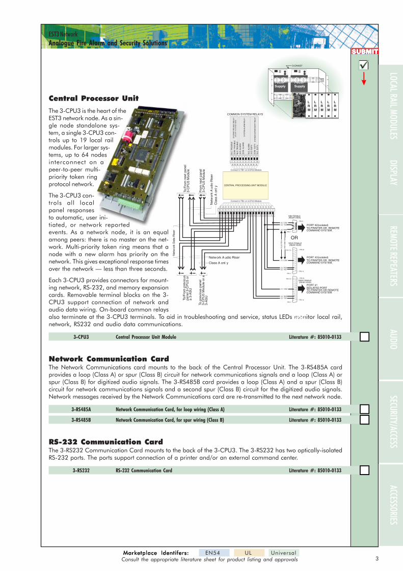
Central Processor Unit
The 3-CPU3 is the heart of theEST3 network node. As a sin-gle node standalone sys-tem, a single 3-CPU3 con-trols up to 19 local railmodules. For larger sys-tems, up to 64 nodesinterconnect on apeer-to-peer multi-priority token ringprotocol network.
The 3-CPU3 con-trols all localpanel responsesto automatic, user ini-tiated, or network reportedevents. As a network node, it is an equalamong peers: there is no master on the net-work. Multi-priority token ring means that anode with a new alarm has priority on thenetwork. This gives exceptional response timesover the network — less than three seconds.
Each 3-CPU3 provides connectors for mount-ing network, RS-232, and memory expansioncards. Removable terminal blocks on the 3-CPU3 support connection of network andaudio data wiring. On-board common relaysalso terminate at the 3-CPU3 terminals. To aid in troubleshooting and service, status LEDs monitor local rail,network, RS232 and audio data communications.
3-CPU3 Central Processor Unit Module Literature #: 85010-0133
Network Communication CardThe Network Communications card mounts to the back of the Central Processor Unit. The 3-RS485A cardprovides a loop (Class A) or spur (Class B) circuit for network communications signals and a loop (Class A) orspur (Class B) for digitized audio signals. The 3-RS485B card provides a loop (Class A) and a spur (Class B)circuit for network communications signals and a second spur (Class B) circuit for the digitized audio signals.Network messages received by the Network Communications card are re-transmitted to the next network node.
3-RS485A Network Communication Card, for loop wiring (Class A) Literature #: 85010-0133
3-RS485B Network Communication Card, for spur wiring (Class B) Literature #: 85010-0133
RS-232 Communication CardThe 3-RS232 Communication Card mounts to the back of the 3-CPU3. The 3-RS232 has two optically-isolatedRS-232 ports. The ports support connection of a printer and/or an external command center.
3-RS232 RS-232 Communication Card Literature #: 85010-0133
PowerSupply
PowerSupply
J8
J9
J10
J11
J8
J9
J10
J11
CentralProcessor
UnitModule3-CPU
LRM
LRM
LRM
LRM
LRM
3-CHAS7
3-
CPU3
Marketplace Identifers:Marketplace Identifers:Marketplace Identifers:Marketplace Identifers:Marketplace Identifers: EN54 UL UniversalConsult the appropriate literature sheet for product listing and approvals
4Marketplace Identi fers:Marketplace Identi fers:Marketplace Identi fers:Marketplace Identi fers:Marketplace Identi fers: EN54 UL Universal
Consult the appropriate literature sheet for product listing and approvals
EST3 NetworkAnalogue Fire Alarm and Security Solutions
SUBMITSUBMITSUBMITSUBMITSUBMIT
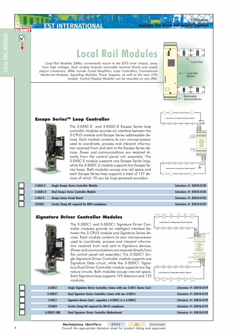
Local Rail ModulesLocal Rail ModulesLocal Rail Modules (LRMs) conveniently mount to the EST3 inner chassis, away
from high voltages. Each module features removable terminal blocks and simpleplug-in connectors. LRMs include Zoned Amplifiers, Loop Controllers, ConventionalHardwired Modules, Signalling Modules, Power Supplies, as well as the main CPU
module. Control Display Modules can be mounted on any LRM.
Local RailModule
RemovableTerminal Blocks
Local Rail
Signature Driver Controller Modules
The 3-SSDC1 and 3-SDDC1 Signature Driver Con-troller modules provide an intelligent interface be-tween the 3-CPU3 module and Signature Series de-vices. Each module contains its own microprocessorused to coordinate, process and interpret informa-tion received from and sent to Signature devices.(Power and communications are received directly fromthe control panel rail assembly.) The 3-SSDC1 Sin-gle Signature Driver Controller module supports oneSignature Data circuit, while the 3-SDDC1 Signa-ture Dual Driver Controller module supports two Sig-nature circuits. Both modules occupy one rail space.Each Signature loop supports 125 detectors and 125modules.
3-SSDC1 Single Signature Driver Controller. Comes with one 3-SDC1 Device Card Literature #: 85010-0129
3-SDDC1 Dual Signature Driver Controller. Comes with two 3-SDC1s Literature #: 85010-0129
3-SDC1 Signature Device Card - upgrades a 3-SSDC1 to a 3-SDDC1 Literature #: 85010-0129
225002 Ferrite Clamp Kit required for EN-54 compliance Literature #: 85010-0129
3-SDDC1-MB Dual Signature Driver Controller Motherboard Literature #: 85010-0129
Loop (Class A) Configuration Shown (Typical)
Circuit #13-EASC-E
& 3-EADC-E
++
+ +
ON
A ABL1 L2
B
LLSCR
EXTERNALCONTACT
L107
0-2
6432168421
ON
A ABL1 L2
B
LLSCR
EXTERNALCONTACT
L107
0-2
6432168421
ON
A ABL1 L2
B
LLSCR
EXTERNALCONTACT
L107
0-2
6432168421
ON
A ABL1 L2
B
LLSCR
EXTERNALCONTACT
L107
0-2
6432168421
ON
A ABL1 L2
B
LLSCR
EXTERNALCONTACT
L107
0-2
6432168421
ON
A ABL1 L2
B
LLSCR
EXTERNALCONTACT
L107
0-2
6432168421
Circuit #23-EADC-E
only
3-EASC-E
or 3-EADC-E
Addressable
Analog
Controller
Module
Loop (Class A) Configuration Shown (Typical)
TB1
TB2
Loop (Class A) Configuration Shown (Typical)
3
Circuit #1
To TB1 on 3-SDDC1 Module
SDC #1 SmokePower
1 2 43 5 6 7 8 9 10
++
Circuit #2
To TB2 on 3-SDDC1 Module
SDC #2 SmokePower
1 2 43 5 6 7 8 9 10
+ +
3-SDDC1
SIGNATURE
DRIVER
CONTROLLER
MODULE
DUAL
Loop (Class A) Configuration Shown (Typical)
LOCA
L RAI
L MOD
ULES
Escape SeriesTM Loop Controller
The 3-EASC-E and 3-EADC-E Escape Series loopcontroller modules provide an interface between the3-CPU3 module and Escape Series addressable de-vices. Each module contains its own microprocessorused to coordinate, process and interpret informa-tion received from and sent to the Escape Series de-vices. Power and communications are received di-rectly from the control panel rail assembly. The3-EASC-E module supports one Escape Series loop,while the 3-EADC-E module supports two Escape Se-ries loops. Both modules occupy one rail space andeach Escape Series loop supports a total of 127 de-vices of which 70 can be loop-powered sounders.
3-EASC-E Single Escape Series Controller Module Literature #: 85010-0130
3-EADC-E Dual Escape Series Controller Module Literature #: 85010-0130
3-EAC-E Escape Series Circuit Board Literature #: 85010-0130
225002 Ferrite Clamp Kit required for EN54 compliance Literature #: 85010-0129
5Marketplace Identifers:Marketplace Identifers:Marketplace Identifers:Marketplace Identifers:Marketplace Identifers: EN54 UL Universal
Consult the appropriate literature sheet for product listing and approvals
EST3 NetworkAnalogue Fire Alarm and Security Solutions
DISPLAYREMOTE REPEATERS
AUDIOSECURITY/ACCESS
ACCESSORIES
SUBMITSUBMITSUBMITSUBMITSUBMIT
EOL
Connect to IDC/NAC 1, 2, 7, or 8NOTIFICATION APPLIANCE CIRCUIT (NAC)
+ +- -
+ +- -
+ +- -
EOL
Detector Base
Connect to IDC 3, 4, 5, or 6IDC/NAC 1, 2, 7, or 8
Detector Base
1 4
2 3
INITIATING DEVICE CIRCUIT (IDC)
IDC
/NA
C #
1
IDC
/NA
C #
2
IDC
#3
IDC
#4
NA
C IN
1/2
To TB1 on Module
1 2 43 5 6 7 8 9 10
TX JP1
JP3
11
11
22
22
33
33
JP2
JP4
RX
TB1
TB2
IDC
/NA
C #
8
IDC
/NA
C #
7
IDC
#6
IDC
#5
NA
C IN 7/
8
124 35678910
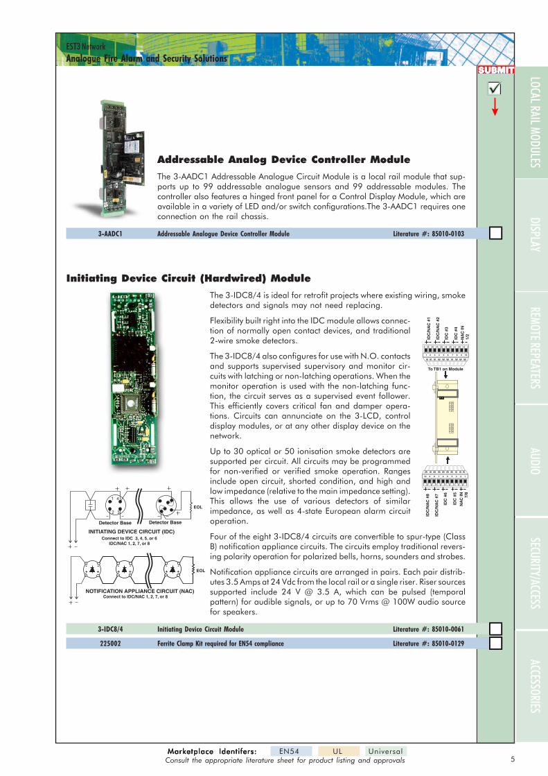
Initiating Device Circuit (Hardwired) Module
The 3-IDC8/4 is ideal for retrofit projects where existing wiring, smokedetectors and signals may not need replacing.
Flexibility built right into the IDC module allows connec-tion of normally open contact devices, and traditional2-wire smoke detectors.
The 3-IDC8/4 also configures for use with N.O. contactsand supports supervised supervisory and monitor cir-cuits with latching or non-latching operations. When themonitor operation is used with the non-latching func-tion, the circuit serves as a supervised event follower.This efficiently covers critical fan and damper opera-tions. Circuits can annunciate on the 3-LCD, controldisplay modules, or at any other display device on thenetwork.
Up to 30 optical or 50 ionisation smoke detectors aresupported per circuit. All circuits may be programmedfor non-verified or verified smoke operation. Rangesinclude open circuit, shorted condition, and high andlow impedance (relative to the main impedance setting).This allows the use of various detectors of similarimpedance, as well as 4-state European alarm circuitoperation.
Four of the eight 3-IDC8/4 circuits are convertible to spur-type (ClassB) notification appliance circuits. The circuits employ traditional revers-ing polarity operation for polarized bells, horns, sounders and strobes.
Notification appliance circuits are arranged in pairs. Each pair distrib-utes 3.5 Amps at 24 Vdc from the local rail or a single riser. Riser sourcessupported include 24 V @ 3.5 A, which can be pulsed (temporalpattern) for audible signals, or up to 70 Vrms @ 100W audio sourcefor speakers.
3-IDC8/4 Initiating Device Circuit Module Literature #: 85010-0061
225002 Ferrite Clamp Kit required for EN54 compliance Literature #: 85010-0129
LOCAL RAIL MODULESAddressable Analog Device Controller Module
The 3-AADC1 Addressable Analogue Circuit Module is a local rail module that sup-ports up to 99 addressable analogue sensors and 99 addressable modules. Thecontroller also features a hinged front panel for a Control Display Module, which areavailable in a variety of LED and/or switch configurations.The 3-AADC1 requires oneconnection on the rail chassis.
3-AADC1 Addressable Analogue Device Controller Module Literature #: 85010-0103
6Marketplace Identi fers:Marketplace Identi fers:Marketplace Identi fers:Marketplace Identi fers:Marketplace Identi fers: EN54 UL Universal
Consult the appropriate literature sheet for product listing and approvals
EST3 NetworkAnalogue Fire Alarm and Security Solutions
SUBMITSUBMITSUBMITSUBMITSUBMIT
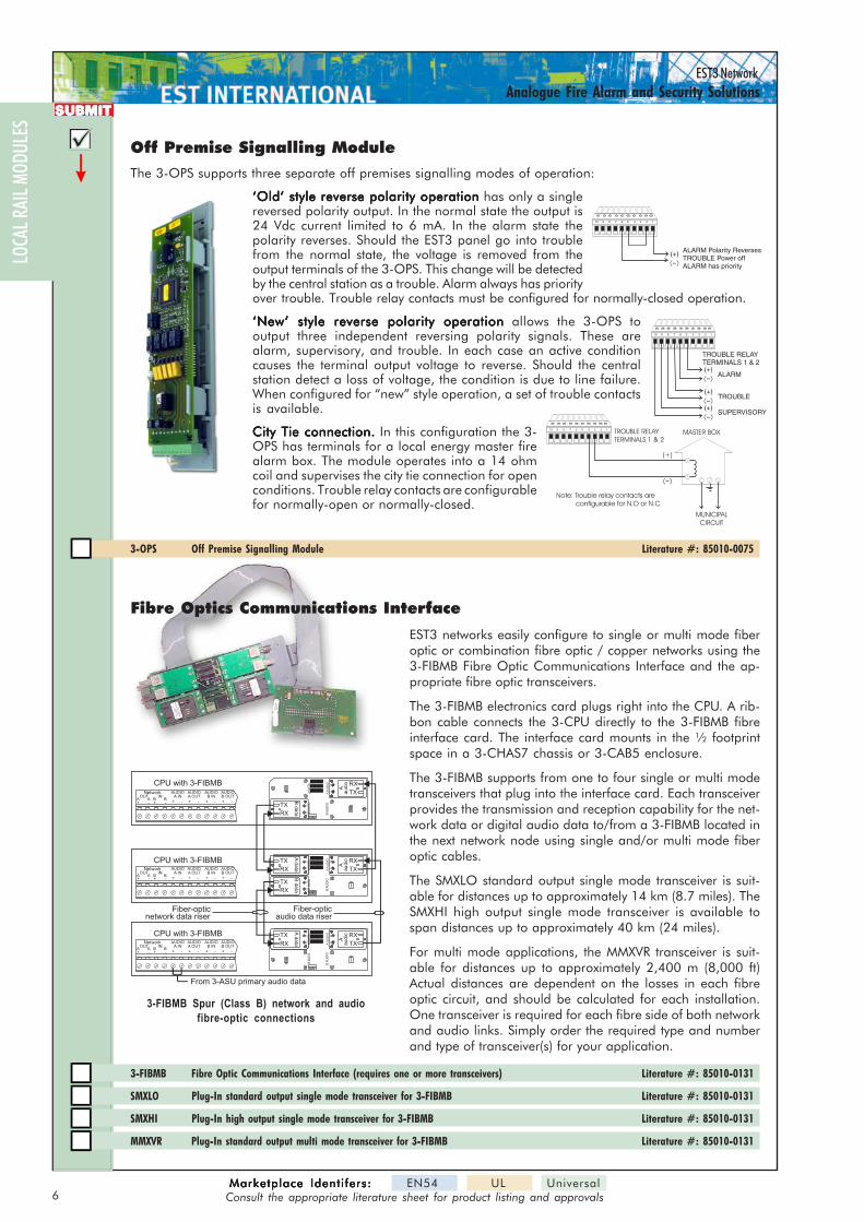
Off Premise Signalling Module
The 3-OPS supports three separate off premises signalling modes of operation:
‘Old’ style reverse polarity operation‘Old’ style reverse polarity operation‘Old’ style reverse polarity operation‘Old’ style reverse polarity operation‘Old’ style reverse polarity operation has only a singlereversed polarity output. In the normal state the output is24 Vdc current limited to 6 mA. In the alarm state thepolarity reverses. Should the EST3 panel go into troublefrom the normal state, the voltage is removed from theoutput terminals of the 3-OPS. This change will be detectedby the central station as a trouble. Alarm always has priorityover trouble. Trouble relay contacts must be configured for normally-closed operation.
‘New’ style reverse polarity operation‘New’ style reverse polarity operation‘New’ style reverse polarity operation‘New’ style reverse polarity operation‘New’ style reverse polarity operation allows the 3-OPS tooutput three independent reversing polarity signals. These arealarm, supervisory, and trouble. In each case an active conditioncauses the terminal output voltage to reverse. Should the centralstation detect a loss of voltage, the condition is due to line failure.When configured for “new” style operation, a set of trouble contactsis available.
City Tie connection.City Tie connection.City Tie connection.City Tie connection.City Tie connection. In this configuration the 3-OPS has terminals for a local energy master firealarm box. The module operates into a 14 ohmcoil and supervises the city tie connection for openconditions. Trouble relay contacts are configurablefor normally-open or normally-closed.
3-OPS Off Premise Signalling Module Literature #: 85010-0075
TROUBLE RELAYTERMINALS 1 & 2
124 35678910
MUNICIPALCIRCUIT
(+)
MASTER BOX
Note: Trouble relay contacts areconfigurable for N.O or N.C
124 35678910
(+)
(+)
(+)
ALARM
TROUBLE RELAYTERMINALS 1 & 2
TROUBLE
SUPERVISORY
124 35678910
(+) ALARM Polarity ReversesTROUBLE Power offALARM has priority
LOCA
L RAI
L MOD
ULES
Fiber-opticnetwork data riser
Fiber-opticaudio data riser
From 3-ASU primary audio data
AA
UD
IOB
AU
DIO
AD
ATA
BD
ATA
RX
TX
RX
TX
RX
TX
AA
UD
IOB
AU
DIO
AD
ATA
BD
ATA
RX
TX
RX
TX
CPU with 3-FIBMB
CPU with 3-FIBMB
Ada
taRX
TX RX
TX
Aau
dio
Ad
ataRX
TX
RX
TX
Bda
ta
RX
TX
Aau
dio
CPU with 3-FIBMB
AA
UD
IOB
AU
DIO
AD
ATA
BD
ATA
RX
TX
RX
TX
RX
TX
Bda
ta
RX
TX
Aau
dio
NetworkOUT IN
A+
A-
B+
B-
AUDIOA IN
+ -
AUDIOA OUT
+ -
AUDIOB IN
+ -
AUDIOB OUT
+ -
NetworkOUT IN
A+
A-
B+
B-
AUDIOA IN
+ -
AUDIOA OUT
+ -
AUDIOB IN
+ -
AUDIOB OUT
+ -
NetworkOUT IN
A+
A-
B+
B-
AUDIOA IN
+ -
AUDIOA OUT
+ -
AUDIOB IN
+ -
AUDIOB OUT
+ -
Fibre Optics Communications Interface
EST3 networks easily configure to single or multi mode fiberoptic or combination fibre optic / copper networks using the3-FIBMB Fibre Optic Communications Interface and the ap-propriate fibre optic transceivers.
The 3-FIBMB electronics card plugs right into the CPU. A rib-bon cable connects the 3-CPU directly to the 3-FIBMB fibreinterface card. The interface card mounts in the ½ footprintspace in a 3-CHAS7 chassis or 3-CAB5 enclosure.
The 3-FIBMB supports from one to four single or multi modetransceivers that plug into the interface card. Each transceiverprovides the transmission and reception capability for the net-work data or digital audio data to/from a 3-FIBMB located inthe next network node using single and/or multi mode fiberoptic cables.
The SMXLO standard output single mode transceiver is suit-able for distances up to approximately 14 km (8.7 miles). TheSMXHI high output single mode transceiver is available tospan distances up to approximately 40 km (24 miles).
For multi mode applications, the MMXVR transceiver is suit-able for distances up to approximately 2,400 m (8,000 ft)Actual distances are dependent on the losses in each fibreoptic circuit, and should be calculated for each installation.One transceiver is required for each fibre side of both networkand audio links. Simply order the required type and numberand type of transceiver(s) for your application.
3-FIBMB Fibre Optic Communications Interface (requires one or more transceivers) Literature #: 85010-0131
SMXLO Plug-In standard output single mode transceiver for 3-FIBMB Literature #: 85010-0131
SMXHI Plug-In high output single mode transceiver for 3-FIBMB Literature #: 85010-0131
MMXVR Plug-In standard output multi mode transceiver for 3-FIBMB Literature #: 85010-0131
3-FIBMB Spur (Class B) network and audiofibre-optic connections
7Marketplace Identifers:Marketplace Identifers:Marketplace Identifers:Marketplace Identifers:Marketplace Identifers: EN54 UL Universal
Consult the appropriate literature sheet for product listing and approvals
EST3 NetworkAnalogue Fire Alarm and Security Solutions
DISPLAYREMOTE REPEATERS
AUDIOSECURITY/ACCESS
ACCESSORIES
SUBMITSUBMITSUBMITSUBMITSUBMIT
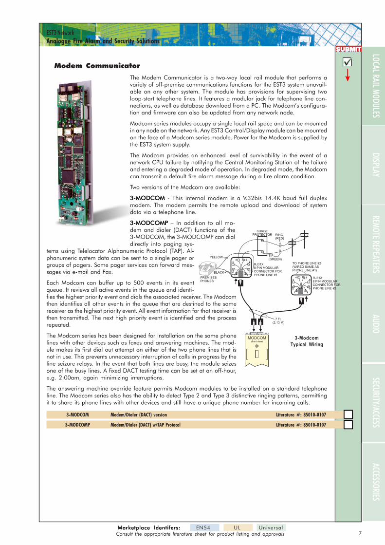
Modem Communicator
The Modem Communicator is a two-way local rail module that performs avariety of off-premise communications functions for the EST3 system unavail-able on any other system. The module has provisions for supervising twoloop-start telephone lines. It features a modular jack for telephone line con-nections, as well as database download from a PC. The Modcom’s configura-tion and firmware can also be updated from any network node.
Modcom series modules occupy a single local rail space and can be mountedin any node on the network. Any EST3 Control/Display module can be mountedon the face of a Modcom series module. Power for the Modcom is supplied bythe EST3 system supply.
The Modcom provides an enhanced level of survivability in the event of anetwork CPU failure by notifying the Central Monitoring Station of the failureand entering a degraded mode of operation. In degraded mode, the Modcomcan transmit a default fire alarm message during a fire alarm condition.
Two versions of the Modcom are available:
3-MODCOM3-MODCOM3-MODCOM3-MODCOM3-MODCOM - This internal modem is a V.32bis 14.4K baud full duplexmodem. The modem permits the remote upload and download of systemdata via a telephone line.
3-MODCOMP 3-MODCOMP 3-MODCOMP 3-MODCOMP 3-MODCOMP – In addition to all mo-dem and dialer (DACT) functions of the3-MODCOM, the 3-MODCOMP can dialdirectly into paging sys-
tems using Telelocator Alphanumeric Protocol (TAP). Al-phanumeric system data can be sent to a single pager orgroups of pagers. Some pager services can forward mes-sages via e-mail and Fax.
Each Modcom can buffer up to 500 events in its eventqueue. It reviews all active events in the queue and identi-fies the highest priority event and dials the associated receiver. The Modcomthen identifies all other events in the queue that are destined to the samereceiver as the highest priority event. All event information for that receiver isthen transmitted. The next high priority event is identified and the processrepeated.
The Modcom series has been designed for installation on the same phonelines with other devices such as faxes and answering machines. The mod-ule makes its first dial out attempt on either of the two phone lines that isnot in use. This prevents unnecessary interruption of calls in progress by theline seizure relays. In the event that both lines are busy, the module seizesone of the busy lines. A fixed DACT testing time can be set at an off-hour,e.g. 2:00am, again minimizing interruptions.
The answering machine override feature permits Modcom modules to be installed on a standard telephoneline. The Modcom series also has the ability to detect Type 2 and Type 3 distinctive ringing patterns, permittingit to share its phone lines with other devices and still have a unique phone number for incoming calls.
3-MODCOM Modem/Dialer (DACT) version Literature #: 85010-0107
3-MODCOMP Modem/Dialer (DACT) w/TAP Protocol Literature #: 85010-0107
RJ31X8 PIN MODULARCONNECTOR FORPHONE LINE #2
TO PHONE LINE #2(WIRED SAME ASPHONE LINE #1)
1 8
7
654
3
2
RING(RED)
TIP(GREEN)
RJ31X8 PIN MODULARCONNECTOR FORPHONE LINE #1
PREMISESPHONES
7 Ft.(2.13 M)
BLACK
YELLOW
SURGEPROTECTOR
1 8
7
654
3
2
LINE 1 LINE 2
MODCOM(front view)
3-ModcomTypical Wiring
LOCAL RAIL MODULES
8Marketplace Identi fers:Marketplace Identi fers:Marketplace Identi fers:Marketplace Identi fers:Marketplace Identi fers: EN54 UL Universal
Consult the appropriate literature sheet for product listing and approvals
EST3 NetworkAnalogue Fire Alarm and Security Solutions
LOCA
L RAI
L MOD
ULES
SUBMITSUBMITSUBMITSUBMITSUBMIT
PowerSupply
PowerSupply
J8
J9
J10
J11
J8
J9
J10
J11
CentralProcessor
Unit3-CPU3
LRM
AlarmSilence
PanelSilence DrillReset
Alarm Sup'y Trouble Monitor
1
4
7
2
5
8
0
3
6
9
Power Test CPUFail
GNDFault Disable
Previous
Message
Next
ExpandedMessage
CommandMenu
Date and Time
EST3 system
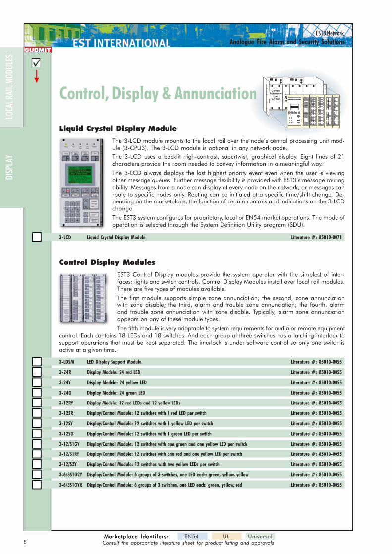
Liquid Crystal Display Module
The 3-LCD module mounts to the local rail over the node’s central processing unit mod-ule (3-CPU3). The 3-LCD module is optional in any network node.
The 3-LCD uses a backlit high-contrast, supertwist, graphical display. Eight lines of 21characters provide the room needed to convey information in a meaningful way.
The 3-LCD always displays the last highest priority event even when the user is viewingother message queues. Further message flexibility is provided with EST3’s message routingability. Messages from a node can display at every node on the network, or messages canroute to specific nodes only. Routing can be initiated at a specific time/shift change. De-pending on the marketplace, the function of certain controls and indications on the 3-LCDchange.
The EST3 system configures for proprietary, local or EN54 market operations. The mode ofoperation is selected through the System Definition Utility program (SDU).
3-LCD Liquid Crystal Display Module Literature #: 85010-0071
Control Display Modules
EST3 Control Display modules provide the system operator with the simplest of inter-faces: lights and switch controls. Control Display Modules install over local rail modules.There are five types of modules available.
The first module supports simple zone annunciation; the second, zone annunciationwith zone disable; the third, alarm and trouble zone annunciation; the fourth, alarmand trouble zone annunciation with zone disable. Typically, alarm zone annunciationappears on any of these module types.
The fifth module is very adaptable to system requirements for audio or remote equipmentcontrol. Each contains 18 LEDs and 18 switches. And each group of three switches has a latching-interlock tosupport operations that must be kept separated. The interlock is under software control so only one switch isactive at a given time.
3-LDSM LED Display Support Module Literature #: 85010-0055
3-24R Display Module: 24 red LED Literature #: 85010-0055
3-24Y Display Module: 24 yellow LED Literature #: 85010-0055
3-24G Display Module: 24 green LED Literature #: 85010-0055
3-12RY Display Module: 12 red LEDs and 12 yellow LEDs Literature #: 85010-0055
3-12SR Display/Control Module: 12 switches with 1 red LED per switch Literature #: 85010-0055
3-12SY Display/Control Module: 12 switches with 1 yellow LED per switch Literature #: 85010-0055
3-12SG Display/Control Module: 12 switches with 1 green LED per switch Literature #: 85010-0055
3-12/S1GY Display/Control Module: 12 switches with one green and one yellow LED per switch Literature #: 85010-0055
3-12/S1RY Display/Control Module: 12 switches with one red and one yellow LED per switch Literature #: 85010-0055
3-12/S2Y Display/Control Module: 12 switches with two yellow LEDs per switch Literature #: 85010-0055
3-6/3S1G2Y Display/Control Module: 6 groups of 3 switches, one LED each: green, yellow, yellow Literature #: 85010-0055
3-6/3S1GYR Display/Control Module: 6 groups of 3 switches, one LED each: green, yellow, red Literature #: 85010-0055
Control, Display & AnnunciationControl, Display & Annunciation
DISP
LAY
9Marketplace Identifers:Marketplace Identifers:Marketplace Identifers:Marketplace Identifers:Marketplace Identifers: EN54 UL Universal
Consult the appropriate literature sheet for product listing and approvals
EST3 NetworkAnalogue Fire Alarm and Security Solutions
REMOTE REPEATERSAUDIO
SECURITY/ACCESSACCESSORIES
SUBMITSUBMITSUBMITSUBMITSUBMIT
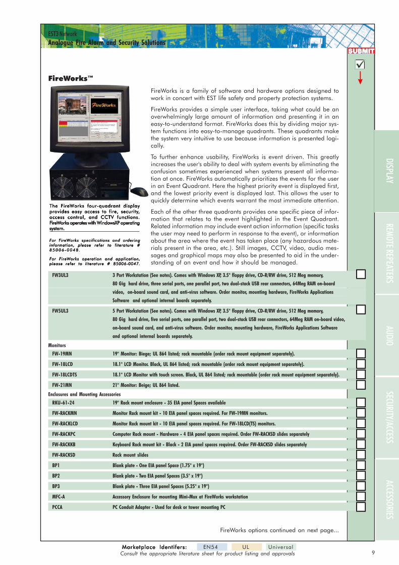
FireWorks™
FireWorks is a family of software and hardware options designed towork in concert with EST life safety and property protection systems.
FireWorks provides a simple user interface, taking what could be anoverwhelmingly large amount of information and presenting it in aneasy-to-understand format. FireWorks does this by dividing major sys-tem functions into easy-to-manage quadrants. These quadrants makethe system very intuitive to use because information is presented logi-cally.
To further enhance usability, FireWorks is event driven. This greatlyincreases the user's ability to deal with system events by eliminating theconfusion sometimes experienced when systems present all informa-tion at once. FireWorks automatically prioritizes the events for the userin an Event Quadrant. Here the highest priority event is displayed first,and the lowest priority event is displayed last. This allows the user toquickly determine which events warrant the most immediate attention.
Each of the other three quadrants provides one specific piece of infor-mation that relates to the event highlighted in the Event Quadrant.Related information may include event action information (specific tasksthe user may need to perform in response to the event), or informationabout the area where the event has taken place (any hazardous mate-rials present in the area, etc.). Still images, CCTV, video, audio mes-sages and graphical maps may also be presented to aid in the under-standing of an event and how it should be managed.
FW3UL3 3 Port Workstation (See notes). Comes with Windows XP, 3.5" floppy drive, CD-R/RW drive, 512 Meg memory,
80 Gig hard drive, three serial ports, one parallel port, two dual-stack USB rear connectors, 64Meg RAM on-board
video, on-board sound card, and anti-virus software. Order monitor, mounting hardware, FireWorks Applications
Software and optional internal boards separately.
FW5UL3 5 Port Workstation (See notes). Comes with Windows XP, 3.5" floppy drive, CD-R/RW drive, 512 Meg memory,
80 Gig hard drive, five serial ports, one parallel port, two dual-stack USB rear connectors, 64Meg RAM on-board video,
on-board sound card, and anti-virus software. Order monitor, mounting hardware, FireWorks Applications Software
and optional internal boards separately.
Monitors
FW-19MN 19" Monitor: Biege; UL 864 listed; rack mountable (order rack mount equipment separately).
FW-18LCD 18.1" LCD Monitor. Black, UL 864 listed; rack mountable (order rack mount equipment separately).
FW-18LCDTS 18.1" LCD Monitor with touch screen. Black, UL 864 listed; rack mountable (order rack mount equipment separately).
FW-21MN 21" Monitor: Beige; UL 864 listed.
Enclosures and Mounting Accessories
RKU-61-24 19" Rack mount enclosure - 35 EIA panel Spaces available
FW-RACKMN Monitor Rack mount kit - 10 EIA panel spaces required. For FW-19MN monitors.
FW-RACKLCD Monitor Rack mount kit - 10 EIA panel spaces required. For FW-18LCD(TS) monitors.
FW-RACKPC Computer Rack mount - Hardware - 4 EIA panel spaces required. Order FW-RACKSD slides separately
FW-RACKKB Keyboard Rack mount kit - Black - 2 EIA panel spaces required. Order FW-RACKSD slides separately
FW-RACKSD Rack mount slides
BP1 Blank plate - One EIA panel Space (1.75" x 19")
BP2 Blank plate - Two EIA panel Spaces (3.5" x 19")
BP3 Blank plate - Three EIA panel Spaces (5.25" x 19")
MFC-A Accessory Enclosure for mounting Mini-Mux at FireWorks workstation
PCCA PC Conduit Adapter - Used for desk or tower mounting PC
The FireWorks four-quadrant displayThe FireWorks four-quadrant displayThe FireWorks four-quadrant displayThe FireWorks four-quadrant displayThe FireWorks four-quadrant displayprovides easy access to fire, securityprovides easy access to fire, securityprovides easy access to fire, securityprovides easy access to fire, securityprovides easy access to fire, security,,,,,access control, and CCTV functions.access control, and CCTV functions.access control, and CCTV functions.access control, and CCTV functions.access control, and CCTV functions.FFFFFireWireWireWireWireWorks operates with Windowsorks operates with Windowsorks operates with Windowsorks operates with Windowsorks operates with WindowsXPXPXPXPXP operating operating operating operating operatingsystem.system.system.system.system.
For FireWorks specifications and orderingFor FireWorks specifications and orderingFor FireWorks specifications and orderingFor FireWorks specifications and orderingFor FireWorks specifications and orderinginformation, please refer to l i terature #information, please refer to l i terature #information, please refer to l i terature #information, please refer to l i terature #information, please refer to l i terature #8 5 0 0 6 - 0 0 4 8 .8 5 0 0 6 - 0 0 4 8 .8 5 0 0 6 - 0 0 4 8 .8 5 0 0 6 - 0 0 4 8 .8 5 0 0 6 - 0 0 4 8 .
For FireWorks operation and application,For FireWorks operation and application,For FireWorks operation and application,For FireWorks operation and application,For FireWorks operation and application,please refer to l iterature # 85006-0047.please refer to l iterature # 85006-0047.please refer to l iterature # 85006-0047.please refer to l iterature # 85006-0047.please refer to l iterature # 85006-0047.
DISPLAY
FireWorks options continued on next page...

10Marketplace Identifers:Marketplace Identifers:Marketplace Identifers:Marketplace Identifers:Marketplace Identifers: EN54 UL Universal
Consult the appropriate literature sheet for product listing and approvals
EST3 NetworkAnalogue Fire Alarm and Security Solutions
LOCA
L RAI
L MOD
ULES
SUBMITSUBMITSUBMITSUBMITSUBMIT
Video Display Utility for Text Annunciation
The 3-VDUT Video Display Utility for Text is a software package that runs on anIBM-compatible personal computer. The software allows ancillary annunciation ofEST3 system events in text format. The 3-VDUT is a 32-bit program compatiblewith Windows95®, Windows98® or WindowsNT® 4.0 operating systems.
3-VDUT Video Display Utility for Text Annunciation Software Literature #: 85010-0117
DISP
LAY
Colour Graphics Software
FW-CGS (no common control)
FW-CGSUL (with common control)
Access Control Database Software
ACDB8 (controls up to eight doors)
ACDB8+ (controls more than eight doors)
SiteVIsion Software
SV Provides on-screen annunciation of CCTV at FireWorks PC
SV+ Provides on-screen annunciation of CCTV at FireWorks PC (with on-screen control)
Option cards
FW-SP2 Serial Port for UL/ULC listed systems. Provides 2 additional serial ports for FW3UL3 or FW2UL2 or FW2 workstations.
FW-VIDTVC Card for UL/ULC listed systems. Required when using SV+ software with FW3UL3 or FW5UL3.
FW-MOD Modem for UL/ULC listed systems - 56K baud V.90
FW-SNDSP Computer Speakers Black
FW-VIDVC2 Video card for dual monitors (FW3UL3 and FW5UL3)
Optional Accessories
Mini-Mux Communication Interface Board - UL listed for extending FireWorks to Fire Panel Communications.
FCOM-FIB Fiber Optic data line card used with Mini-Mux
FW-XPC RS-232 extender. Allows FireWorks with no common controls to communicate to Fire Panels over copper connection
up to 3 miles. Works in conjunction with FW-XPL ordered separately
FW-XPL RS-232 extender. Allows Fire Panel (EST3, EST2, IRC-3, and FCC) to communicate with FireWorks with no common controls
over copper connection up to 3 miles. Mounts in 1/2 foot print space in control panel.
Printers
PT-IP Parallel Printer 120V
PT-IP-220 Parallel Printer 220V
For FireWorks specifications and ordering information, pleaseFor FireWorks specifications and ordering information, pleaseFor FireWorks specifications and ordering information, pleaseFor FireWorks specifications and ordering information, pleaseFor FireWorks specifications and ordering information, pleaserefer to l iterature # 85006-0048.refer to l iterature # 85006-0048.refer to l iterature # 85006-0048.refer to l iterature # 85006-0048.refer to l iterature # 85006-0048.
For FireWorks operation and application, please refer toFor FireWorks operation and application, please refer toFor FireWorks operation and application, please refer toFor FireWorks operation and application, please refer toFor FireWorks operation and application, please refer toliterature # 85006-0047.literature # 85006-0047.literature # 85006-0047.literature # 85006-0047.literature # 85006-0047.
FireWorks (options)
11Marketplace Identifers:Marketplace Identifers:Marketplace Identifers:Marketplace Identifers:Marketplace Identifers: EN54 UL Universal
Consult the appropriate literature sheet for product listing and approvals
EST3 NetworkAnalogue Fire Alarm and Security Solutions
AUDIOSECURITY/ACCESS
ACCESSORIES
SUBMITSUBMITSUBMITSUBMITSUBMIT
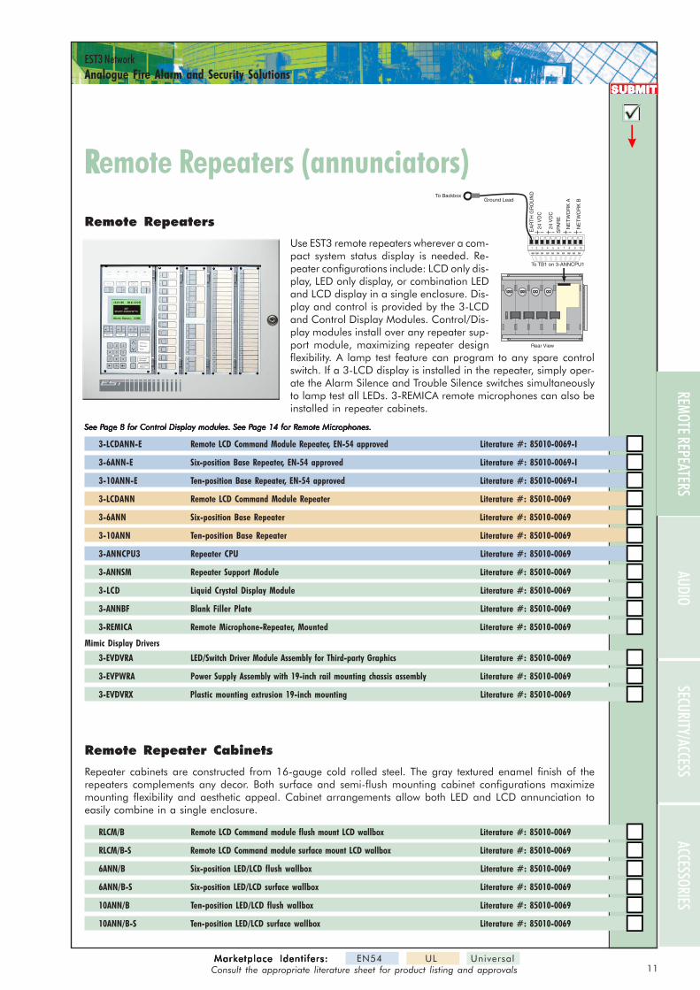
Remote Repeaters
Use EST3 remote repeaters wherever a com-pact system status display is needed. Re-peater configurations include: LCD only dis-play, LED only display, or combination LEDand LCD display in a single enclosure. Dis-play and control is provided by the 3-LCDand Control Display Modules. Control/Dis-play modules install over any repeater sup-port module, maximizing repeater designflexibility. A lamp test feature can program to any spare controlswitch. If a 3-LCD display is installed in the repeater, simply oper-ate the Alarm Silence and Trouble Silence switches simultaneouslyto lamp test all LEDs. 3-REMICA remote microphones can also beinstalled in repeater cabinets.
See PSee PSee PSee PSee Page 8 for Control Display modules. See Page 8 for Control Display modules. See Page 8 for Control Display modules. See Page 8 for Control Display modules. See Page 8 for Control Display modules. See Page 14 for Rage 14 for Rage 14 for Rage 14 for Rage 14 for Remote Microphones.emote Microphones.emote Microphones.emote Microphones.emote Microphones.
3-LCDANN-E Remote LCD Command Module Repeater, EN-54 approved Literature #: 85010-0069-I
3-6ANN-E Six-position Base Repeater, EN-54 approved Literature #: 85010-0069-I
3-10ANN-E Ten-position Base Repeater, EN-54 approved Literature #: 85010-0069-I
3-LCDANN Remote LCD Command Module Repeater Literature #: 85010-0069
3-6ANN Six-position Base Repeater Literature #: 85010-0069
3-10ANN Ten-position Base Repeater Literature #: 85010-0069
3-ANNCPU3 Repeater CPU Literature #: 85010-0069
3-ANNSM Repeater Support Module Literature #: 85010-0069
3-LCD Liquid Crystal Display Module Literature #: 85010-0069
3-ANNBF Blank Filler Plate Literature #: 85010-0069
3-REMICA Remote Microphone-Repeater, Mounted Literature #: 85010-0069
Mimic Display Drivers
3-EVDVRA LED/Switch Driver Module Assembly for Third-party Graphics Literature #: 85010-0069
3-EVPWRA Power Supply Assembly with 19-inch rail mounting chassis assembly Literature #: 85010-0069
3-EVDVRX Plastic mounting extrusion 19-inch mounting Literature #: 85010-0069
Remote Repeater Cabinets
Repeater cabinets are constructed from 16-gauge cold rolled steel. The gray textured enamel finish of therepeaters complements any decor. Both surface and semi-flush mounting cabinet configurations maximizemounting flexibility and aesthetic appeal. Cabinet arrangements allow both LED and LCD annunciation toeasily combine in a single enclosure.
RLCM/B Remote LCD Command module flush mount LCD wallbox Literature #: 85010-0069
RLCM/B-S Remote LCD Command module surface mount LCD wallbox Literature #: 85010-0069
6ANN/B Six-position LED/LCD flush wallbox Literature #: 85010-0069
6ANN/B-S Six-position LED/LCD surface wallbox Literature #: 85010-0069
10ANN/B Ten-position LED/LCD flush wallbox Literature #: 85010-0069
10ANN/B-S Ten-position LED/LCD surface wallbox Literature #: 85010-0069
Remote Remote Repeaters (annunciators)epeaters (annunciators)
TX RX
TXRXTX RX
TXRXTX RX
TXRXTX RX
TXRX
EA
RT
H G
RO
UN
DTo BackboxGround Lead
Rear View
24V
DC
24V
DC
NE
TW
OR
K A
NE
TW
OR
K B
SPA
RE
To TB1 on 3-ANNCPU1
1 2 43 5 6 7 8 9 10
REMOTE REPEATERS
12Marketplace Identifers:Marketplace Identifers:Marketplace Identifers:Marketplace Identifers:Marketplace Identifers: EN54 UL Universal
Consult the appropriate literature sheet for product listing and approvals
EST3 NetworkAnalogue Fire Alarm and Security Solutions
DISP
LAY
LOCA
L RAI
L MOD
ULES
SUBMITSUBMITSUBMITSUBMITSUBMIT
24VDC FROM 3-PPS/MOR 3-BPS/M POWER RISER
FROM PREVIOUS PANELRS-485 NETWORK DATA
POWER MODULE
RS-485 NETWORK DATATO NEXT PANEL
24VDC TO NEXT
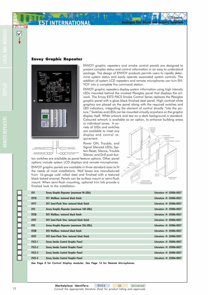
Envoy Graphic Repeater
ENVOY graphic repeaters and smoke control panels are designed topresent complex status and control information in an easy to understandpackage. The design of ENVOY products permits users to rapidly deter-mine system status and easily operate associated system controls. Theaddition of system LCD repeaters and remote microphones can turn EN-VOY into a complete fire command station.
ENVOY graphic repeaters display system information using high intensityLEDs mounted behind the smoked Plexiglas panel that displays the art-work. The Envoy EST3 FACS Smoke Control Series replaces the Plexiglasgraphic panel with a gloss black finished steel panel. High contrast whitegraphics are placed on the panel along with the required switches andLED indicators, integrating the element of control directly “into the pic-ture.” Switches and LEDs can be mounted virtually anywhere on the graphicdisplay itself. White artwork and text on a dark background is standard.Coloured artwork is available as an option, to enhance building areasor individual zones. A va-riety of LEDs and switchesare available to meet anydisplay and control re-quirement.
Power ON, Trouble, andSignal Silenced LEDs; Sys-tem Reset, Silence, TroubleSilence, and Drill push but-
ton switches are available as panel feature options. Other paneloptions include system LCD displays and remote microphones.
ENVOY graphic panels are available in three standard sizes to fitthe needs of most installations. Wall boxes are manufacturedfrom 16-gauge cold rolled steel and finished with a texturedblack baked enamel. Panels can be surface mount or semi-flushmount. When semi-flush mounting, optional trim kits provide afinished look to the installation.
EV1 Envoy Graphic Repeater (maximum 96 LEDs) Literature #: 85006-0037
EV1B EV1 Wallbox: textured black finish Literature #: 85006-0037
EV1T EV1 Semi-Flush Trim: textured black finish Literature #: 85006-0037
EV2 Envoy Graphic Repeater (maximum 160 LEDs) Literature #: 85006-0037
EV2B EV2 Wallbox: textured black finish Literature #: 85006-0037
EV2T EV2 Semi-Flush Trim: textured black finish Literature #: 85006-0037
EV3 Envoy Graphic Repeater (maximum 256 LEDs) Literature #: 85006-0037
EV3B EV3 Wallbox: textured black finish Literature #: 85006-0037
EV3T EV3 Semi-Flush Trim: textured black finish Literature #: 85006-0037
FSCS-1 Envoy Smoke Control Graphic Panel Literature #: 85006-0037
FSCS-2 Envoy Smoke Control Graphic Panel Literature #: 85006-0037
FSCS-3 Envoy Smoke Control Graphic Panel Literature #: 85006-0037
FSCS-4 Envoy Smoke Control Graphic Panel Literature #: 85006-0037
See Page 8 for Control Display modules. See Page 14 for Remote Microphones.See Page 8 for Control Display modules. See Page 14 for Remote Microphones.See Page 8 for Control Display modules. See Page 14 for Remote Microphones.See Page 8 for Control Display modules. See Page 14 for Remote Microphones.See Page 8 for Control Display modules. See Page 14 for Remote Microphones.
Smoked Plexiglas c/w Graphic
Optional 3-EVRMFModule Mounting Frame(7 EIA Panel spaces high)
BP1
Flush TrimOptional
Outer DoorSeparate Hinged
Mounting Rails
Feature Plate
Optional
or
Wallbox
LED Matrix Board
MountingHinged LED/GRAPHIC
Extrusion/Mounting
Driver Board
Chassis
REMO
TE RE
PEAT
ERS
13Marketplace Identifers:Marketplace Identifers:Marketplace Identifers:Marketplace Identifers:Marketplace Identifers: EN54 UL Universal
Consult the appropriate literature sheet for product listing and approvals
EST3 NetworkAnalogue Fire Alarm and Security Solutions
SECURITY/ACCESSACCESSORIES
SUBMITSUBMITSUBMITSUBMITSUBMIT
J7BOUT
J6DIN
J3 J4
BIN
J2
J5
J1
J8 J9
COUT DOUT
AOUTAIN CIN
RAILEXPCARD
J4
J2
J1
TR RX RXTX PRIMARY
AUDIO DATA REMOTE MIC
SECONDARY TELEPHONEPAGEOUT KEY AUDIO AUX
TX
1 2 3 4
TB11 14
AudioSource
Card
J1
TB1TX RX
J3
J2FirePhoneCard
ALL CALL
READY TOPAGE
Page toEvac
Page toAlert
All CallMinus
Page byPhone
0 call(s) pending
DISCONNECT REVIEW CONNECTED
CONNECT REVIEW PENDING ACK
EMERGENCY TELEPHONE
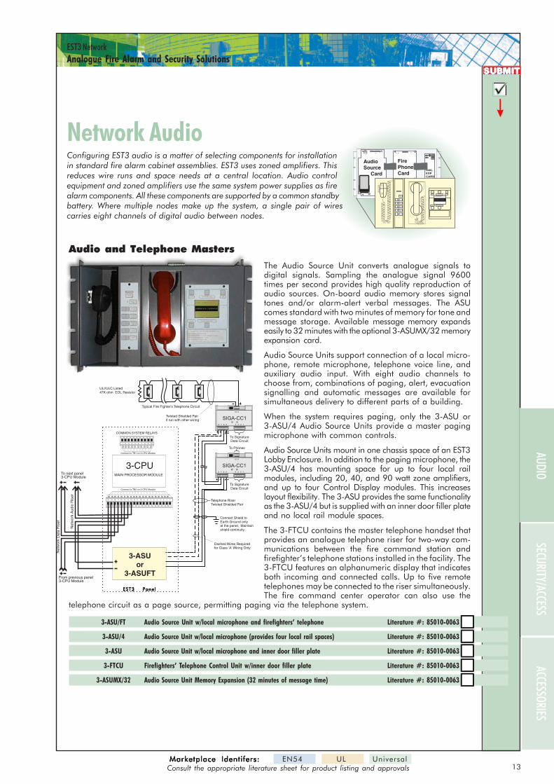
Network AudioNetwork AudioConfiguring EST3 audio is a matter of selecting components for installationin standard fire alarm cabinet assemblies. EST3 uses zoned amplifiers. Thisreduces wire runs and space needs at a central location. Audio controlequipment and zoned amplifiers use the same system power supplies as firealarm components. All these components are supported by a common standbybattery. Where multiple nodes make up the system, a single pair of wirescarries eight channels of digital audio between nodes.
Audio and Telephone Masters
The Audio Source Unit converts analogue signals todigital signals. Sampling the analogue signal 9600times per second provides high quality reproduction ofaudio sources. On-board audio memory stores signaltones and/or alarm-alert verbal messages. The ASUcomes standard with two minutes of memory for tone andmessage storage. Available message memory expandseasily to 32 minutes with the optional 3-ASUMX/32 memoryexpansion card.
Audio Source Units support connection of a local micro-phone, remote microphone, telephone voice line, andauxiliary audio input. With eight audio channels tochoose from, combinations of paging, alert, evacuationsignalling and automatic messages are available forsimultaneous delivery to different parts of a building.
When the system requires paging, only the 3-ASU or3-ASU/4 Audio Source Units provide a master pagingmicrophone with common controls.
Audio Source Units mount in one chassis space of an EST3Lobby Enclosure. In addition to the paging microphone, the3-ASU/4 has mounting space for up to four local railmodules, including 20, 40, and 90 watt zone amplifiers,and up to four Control Display modules. This increaseslayout flexibility. The 3-ASU provides the same functionalityas the 3-ASU/4 but is supplied with an inner door filler plateand no local rail module spaces.
The 3-FTCU contains the master telephone handset thatprovides an analogue telephone riser for two-way com-munications between the fire command station andfirefighter’s telephone stations installed in the facility. The3-FTCU features an alphanumeric display that indicatesboth incoming and connected calls. Up to five remotetelephones may be connected to the riser simultaneously.The fire command center operator can also use the
telephone circuit as a page source, permitting paging via the telephone system.
3-ASU/FT Audio Source Unit w/local microphone and firefighters’ telephone Literature #: 85010-0063
3-ASU/4 Audio Source Unit w/local microphone (provides four local rail spaces) Literature #: 85010-0063
3-ASU Audio Source Unit w/local microphone and inner door filler plate Literature #: 85010-0063
3-FTCU Firefighters’ Telephone Control Unit w/inner door filler plate Literature #: 85010-0063
3-ASUMX/32 Audio Source Unit Memory Expansion (32 minutes of message time) Literature #: 85010-0063
Dashed Wires Requiredfor Class 'A' Wiring Only
Typical Fire Fighter's Telephone Circuit
Telephone RiserTwisted Shielded Pair
Twisted Shielded Pairif run with other wiring
Connect Shield toEarth Ground onlyat the panel. Maintainshield continuity.
To SignatureData Circuit
To SignatureData Circuit
To Phones
ULI/ULC Listed47K ohm EOL Resistor
48 37 26
10
15
9
SIGA-CC1
48 37 26
10
15
9
SIGA-CC1
MAIN PROCESSOR MODULE
Audio Source Unit
1 2 43 5 6 7 8 9 10
COMMON SYSTEM RELAYS
11 112 214 413 315 516 617 718 819 920 10
Net
wor
k D
ata
Ris
er
From previous panel3-CPU Module
To next panel3-CPU Module
Net
wor
k A
udio
Ris
er
Connect to TB1 on 3-CPU Module
Connect to TB2 on 3-CPU Module
3-CPU
3-ASUor
3-ASUFT
EST3 PanelEST3 PanelEST3 PanelEST3 PanelEST3 Panel
AUDIO
14Marketplace Identifers:Marketplace Identifers:Marketplace Identifers:Marketplace Identifers:Marketplace Identifers: EN54 UL Universal
Consult the appropriate literature sheet for product listing and approvals
EST3 NetworkAnalogue Fire Alarm and Security Solutions
REMO
TE RE
PEAT
ERS
DISP
LAY
LOCA
L RAI
L MOD
ULES
SUBMITSUBMITSUBMITSUBMITSUBMIT
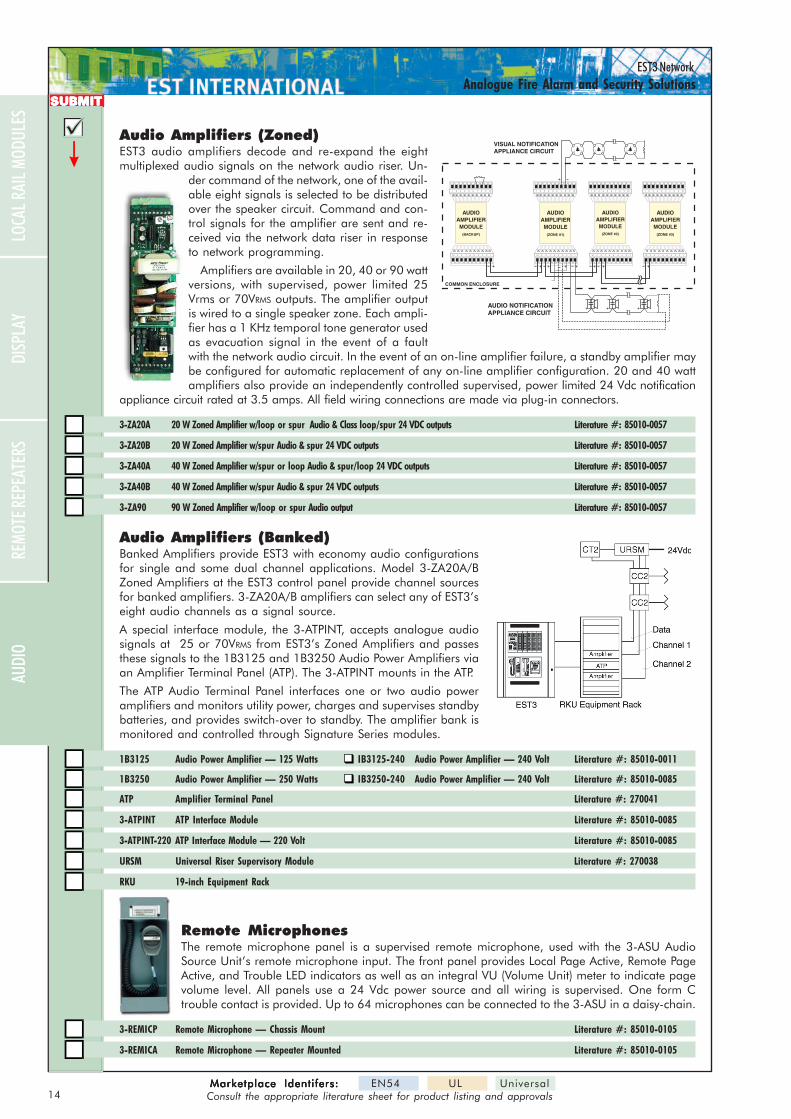
Audio Amplifiers (Zoned)EST3 audio amplifiers decode and re-expand the eightmultiplexed audio signals on the network audio riser. Un-
der command of the network, one of the avail-able eight signals is selected to be distributedover the speaker circuit. Command and con-trol signals for the amplifier are sent and re-ceived via the network data riser in responseto network programming.
Amplifiers are available in 20, 40 or 90 wattversions, with supervised, power limited 25Vrms or 70VRMS outputs. The amplifier outputis wired to a single speaker zone. Each ampli-fier has a 1 KHz temporal tone generator usedas evacuation signal in the event of a faultwith the network audio circuit. In the event of an on-line amplifier failure, a standby amplifier maybe configured for automatic replacement of any on-line amplifier configuration. 20 and 40 wattamplifiers also provide an independently controlled supervised, power limited 24 Vdc notification
appliance circuit rated at 3.5 amps. All field wiring connections are made via plug-in connectors.
3-ZA20A 20 W Zoned Amplifier w/loop or spur Audio & Class loop/spur 24 VDC outputs Literature #: 85010-0057
3-ZA20B 20 W Zoned Amplifier w/spur Audio & spur 24 VDC outputs Literature #: 85010-0057
3-ZA40A 40 W Zoned Amplifier w/spur or loop Audio & spur/loop 24 VDC outputs Literature #: 85010-0057
3-ZA40B 40 W Zoned Amplifier w/spur Audio & spur 24 VDC outputs Literature #: 85010-0057
3-ZA90 90 W Zoned Amplifier w/loop or spur Audio output Literature #: 85010-0057
COMMON ENCLOSURE
AUDIOAMPLIFIERMODULE
(ZONE #1)
AUDIOAMPLIFIERMODULE
(ZONE #2)
AUDIOAMPLIFIERMODULE
(ZONE #3)
AUDIOAMPLIFIERMODULE
(BACKUP)
1 2 43 5 6 7 8 9 101 2 43 5 6 7 8 9 10 1 2 43 5 6 7 8 9 10 1 2 43 5 6 7 8 9 10
124 35678910 124 35678910 124 35678910124 35678910
VISUAL NOTIFICATIONAPPLIANCE CIRCUIT + +
- -+ +- -
+ +- -
AUDIO NOTIFICATIONAPPLIANCE CIRCUIT
Audio Amplifiers (Banked)Banked Amplifiers provide EST3 with economy audio configurationsfor single and some dual channel applications. Model 3-ZA20A/BZoned Amplifiers at the EST3 control panel provide channel sourcesfor banked amplifiers. 3-ZA20A/B amplifiers can select any of EST3’seight audio channels as a signal source.
A special interface module, the 3-ATPINT, accepts analogue audiosignals at 25 or 70VRMS from EST3’s Zoned Amplifiers and passesthese signals to the 1B3125 and 1B3250 Audio Power Amplifiers viaan Amplifier Terminal Panel (ATP). The 3-ATPINT mounts in the ATP.
The ATP Audio Terminal Panel interfaces one or two audio poweramplifiers and monitors utility power, charges and supervises standbybatteries, and provides switch-over to standby. The amplifier bank ismonitored and controlled through Signature Series modules.
1B3125 Audio Power Amplifier — 125 Watts IB3125-240 Audio Power Amplifier — 240 Volt Literature #: 85010-0011
1B3250 Audio Power Amplifier — 250 Watts IB3250-240 Audio Power Amplifier — 240 Volt Literature #: 85010-0085
ATP Amplifier Terminal Panel Literature #: 270041
3-ATPINT ATP Interface Module Literature #: 85010-0085
3-ATPINT-220 ATP Interface Module — 220 Volt Literature #: 85010-0085
URSM Universal Riser Supervisory Module Literature #: 270038
RKU 19-inch Equipment Rack
Remote MicrophonesThe remote microphone panel is a supervised remote microphone, used with the 3-ASU AudioSource Unit’s remote microphone input. The front panel provides Local Page Active, Remote PageActive, and Trouble LED indicators as well as an integral VU (Volume Unit) meter to indicate pagevolume level. All panels use a 24 Vdc power source and all wiring is supervised. One form Ctrouble contact is provided. Up to 64 microphones can be connected to the 3-ASU in a daisy-chain.
3-REMICP Remote Microphone — Chassis Mount Literature #: 85010-0105
3-REMICA Remote Microphone — Repeater Mounted Literature #: 85010-0105
AUDI
O
15Marketplace Identifers:Marketplace Identifers:Marketplace Identifers:Marketplace Identifers:Marketplace Identifers: EN54 UL Universal
Consult the appropriate literature sheet for product listing and approvals
EST3 NetworkAnalogue Fire Alarm and Security Solutions
ACCESSORIES
SUBMITSUBMITSUBMITSUBMITSUBMIT
Security & Access ControlSecurity & Access ControlAs a true multiplex life safety system, EST3 supports fire alarmas well as security and access control functions. The capacityfor this additional functionality is built right into every EST3panel. All that’s needed to take advantage of it is a handful ofspecialized components.
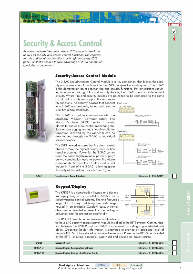
Security/Access Control Module
The 3-SAC Security/Access Control Module is a key component that blends the secu-rity and access control functions into the EST3 multiplex life safety system. The 3-SACis the demarcation point between fire and security functions. For jurisdictions requir-ing independent wiring of fire and security devices, the 3-SAC offers two independentcircuits. Where fire and security devices are permitted to be connected to the samecircuit, both circuits can support fire and secu-rity functions. All security devices that connectto a 3-SAC are designed, tested and listed tostrict fire alarm standards.
The 3-SAC is used in combination with theModcom Modem Communicator. TheModcom’s dialer (DACT) function transmitsalarms to one or more central monitoring sta-tions and/or paging terminals. Additionally, in-formation received by the Modcom can bedownloaded through the 3-SAC to individualsecurity devices.
The EST3 network ensures that fire alarm eventsalways receive the highest priority over routinesignal processing. Power for the 3-SAC comesfrom the same highly-reliable power supply/battery combination used to power fire alarmcomponents. Any Control Display module willmount in front of the 3-SAC, allowing greatflexibility of the system user interface layout.
3-SAC Security/Access Control Module Literature #: 85010-0109
Class A wiring
Class B wiring
TB2
110
3-SAC Module
CRC CRCKPDISPKeypad
BRS-485
Notused
Notused
ARS-485 Ground
G G+ +
From 24 Vdc circuit orlocal 120 Vac
TB2
110
3-SAC Module
CRC CRC
CRC CRC
KPDISPKeypad
KPDISPKeypad
BRS-485
Notused
Notused
ARS-485 Ground
G G+ +
From 24 Vdc circuit orlocal 120 Vac
From 24 Vdc circuit orlocal 120 Vac
120TerminatingResistor
�
120TerminatingResistor
�
Keypad/Display
The KPDISP is a combination keypad and dot-ma-trix display designed for use with the EST3 fire alarm/security/access control systems. The unit features alarge LCD display and telephone-style keypadhoused in an attractive Cycoloy® case. A remov-able cover is provided to prevent accidental keypadactivation and for protection against dirt.
The KPDISP transmits and receives information from/to the 3-SAC security access control module installed in the EST3 system. Communica-tion between the KPDISP and the 3-SAC is supervised, providing unprecedented reli-ability. Credential holder information is encrypted to provide an additional level ofsecurity. KPDISP data is stored in non-volatile memory. Power to the KPDISP is providedby the EST3, ensuring a reliable, supervised and backed-up power source.
KPDISP Keypad/Display Literature #: 85006-0046
KPDISP-CF Keypad/Display Configuration Software Literature #: 85006-0046
KPDISP-ID Keypad/Display Unique Identification Cards Literature #: 85006-0046
DATA
POWER
24 Vdcsupply
From last device
RS-485line
+
–
24 Vdcsupply
To next device
RS-485line
+
–
+ –
+ –
+
–
+
–
SECURITY/ACCESS

16Marketplace Identifers:Marketplace Identifers:Marketplace Identifers:Marketplace Identifers:Marketplace Identifers: EN54 UL Universal
Consult the appropriate literature sheet for product listing and approvals
EST3 NetworkAnalogue Fire Alarm and Security Solutions
AUDI
ORE
MOTE
REPE
ATER
SDI
SPLA
YLO
CAL R
AIL M
ODUL
ES
SUBMITSUBMITSUBMITSUBMITSUBMIT
1
1
TB-2
S1
TB-1
2
J1
2 3 4 5 6 7
Dry contactconnections
From power supply
From Strike/maglock
From plug-intransformer
To batteryRed (+)Black (-)
To next CRC orother device
From 3-SAC moduleor previous CRC
To next CRC or 120 EOLif this is the last device onspur (Class B) or back to3-SAC module if loop(Class A).
�
8 9 10 11 12 13 14 15 16 17 18 19 20 21 22 23
16.5 Vac IN
16.5 Vac IN
+2
4V
IN
-24
VIN
+2
4V
OU
T
-24
VO
UT
Str
ike
PW
R
Str
ike
GN
D
NO
NC
Re
ad
er
PW
R
Re
ad
er
GN
D
Da
ta0
Da
ta1
LE
DA
LE
DB
So
un
de
r
+R
S-4
85
IN
+R
S-4
85
OU
T
-R
S-4
85
IN
-R
S-4
85
OU
T
Lo
op
2IN
Lo
op
1IN
Lo
op
GN
D
C
47 KEOL
47 KEOL
Reader wireconnections
Card Reader Controller
The Card Reader Controller (CRC) provides the power andelectronics required to monitor and control a single door withboth entry and exit readers. The unit is designed to mount inclose proximity to the door it controls, however it can be lo-cated remotely from the readers in retrofit applications. Theunit is housed in an off-white Cycoloy® housing. Its attractivedesign allows for surface mounting in exposed areas.
All access decisions are made locally in the CRC. The CRC’snon-volatile memory can hold schedules and holiday infor-mation for up to 8,000 cardholders. The CRCXM has addi-tional memory, and supports 36,000 cardholders. The memoryalso retains the last 5,000/20,000 events for logging pur-poses. This history information is uploaded at the request ofthe access control database for use in a variety of reports.
The unit provides 12 Vdc @ ½ amp for door strike or magnetic lock requirements. An integral standby batterycan provide up to four hours of service for applications that use electric door strikes. An integral tamper switchis also provided.
Two input circuits are provided for security devices. These are typically used to monitor door position andrequest-to-exit devices. Input circuits can also be configured as a “buzz in” switch to manually unlock the door,or as security input points.
A handicapped feature output is provided to operate mechanical door openers with extended door-open times.This output is activated when a cardholder with the disabled option activated presents his card to the reader.
Each CRC(XM) contains the entire ac-cess control database within its memory.This distribution of intelligence minimizestraffic on the network. Cardholder datais created and stored in the Access Con-trol Database (ACDB) software programthat runs on any compatible PC. This in-formation is then encrypted and sent tothe CRCs by a hardwire or dial-up con-nection.
In a life safety network environment, thePC is simply equipped with a conventionalmodem. The ACDB program then dialsup the network and sends the encrypteddatabase information via the network to the individual CRCs. This allows an ACDB to serve multiple sites. Dial-up data entry also permits multiple tenants to share a common access control system without sharing acommon database. PCs may also be connected directly to the system using a direct serial connection.
CRC Card Reader Controller w/memory for 8,000 cardholders Literature #: 85001-0528
CRCXM Card Reader Controller w/memory for 36,000 cardholders Literature #: 85001-0528
CRCSND CRC Sounder Module Literature #: 85001-0528
12V1A2 12V @1.2AH Standby Battery Literature #: 85001-0528
CRCXF Class 2, 16 Vac Plug in Transformer - 120 Vac to 10 Vac Literature #: 85001-0528
DLSM Data Line Supervisory Monitor Literature #: 85001-0528
ACDB8 Access Control Software - eight doors Literature #: 85010-0098
ACDB8+ Access Control Software - eight-plus doors Literature #: 85010-0098
ACDB-SVR Access Control Database Server Application Software Literature #: 85010-0098
ACDB-CLNT Access Control Database Client Application Software Literature #: 85010-0098
SECU
RITY
/ACC
ESS

17Marketplace Identifers:Marketplace Identifers:Marketplace Identifers:Marketplace Identifers:Marketplace Identifers: EN54 UL Universal
Consult the appropriate literature sheet for product listing and approvals
EST3 NetworkAnalogue Fire Alarm and Security Solutions
ACCESSORIES
SUBMITSUBMITSUBMITSUBMITSUBMIT
Proximity Card Readers
EST3 card readers feature the latest proximity technology that allows cardsto be read when they are held in the vicinity of the reader. This eliminates theneed for reader adjustments required by swipe-type readers. Readers arerated for both indoor and outdoor applications and are constructed ofrugged sealed polycarbonate, which provides a high degree of vandalresistance as well as protection from harsh environments.
CR-5355 Proximity Card Reader
The CR-5355 proximity card reader is available with or without a keypad. The keypadoption provides the additional security offered by a Personal Identification Number(PIN). The CR-5355 mounts on a one-gang electrical box. Dimensions (HWD): 12.7cm x 12.7 cm x 2.54 cm (5.0" x 5.0" x 1.0").
CR-5355 Standard Proximity Card Reader, Charcoal Gray Literature #: 85001-0520
5355AGK0009 HID Brand Proximity Card Reader with Keypad, Charcoal Gray Literature #: 85001-0520
CR-5365 Proximity Card Reader
The CR-5365 is a narrow proximity card reader designed for mounting on doorframesor mullions. The CR-5365 mounts on any sturdy surface. Dimensions (HWD):15.2 cm x 4.36 cm x 2.54 cm (6.0" x 1.7" x 1.0").
CR-5365 Slim-line Proximity Card Reader, Charcoal Gray Literature #: 85001-0521
CR-5395 Proximity Card Reader
The CR-5395 is an aesthetically pleasing proximity card reader that is available with avariety of different colour covers. It mounts on a one-gang electrical box. Dimensions(HWD): 11.9 cm x 7.6 cm x 1.7 cm (4.7" x 3.00" x 0.68").
CR-5395 Proximity Card Reader, Charcoal Gray Literature #: 85001-0522
C-5395G Gray Cover for CR-5395 Literature #: 85001-0522
C-5395B Beige Cover Literature #: 85001-0522
C-5394BL Black Cover Literature #: 85001-0522
C-5394W White Cover Literature #: 85001-0522
CR-6005 Proximity Card Reader
The CR-6005 offers the smallest footprint of any EST proximity card reader. It mountson any sturdy surface. Dimensions (HWD): 7.98 cm x 4.32 cm x 1.3 cm (3.14" x 1.70"x 0.51").
CR-6005 Mini Proximity Card Reader, Charcoal Gray Literature #: 85001-0523
5355AGK0009 Shown
SECURITY/ACCESS

18Marketplace Identifers:Marketplace Identifers:Marketplace Identifers:Marketplace Identifers:Marketplace Identifers: EN54 UL Universal
Consult the appropriate literature sheet for product listing and approvals
EST3 NetworkAnalogue Fire Alarm and Security Solutions
AUDI
ORE
MOTE
REPE
ATER
SDI
SPLA
YLO
CAL R
AIL M
ODUL
ESAC
CESS
ORIES
SUBMITSUBMITSUBMITSUBMITSUBMIT
Proximity Access Cards
EST proximity access control cards offer the most convenient access credential avail-able. To request access, the user simply holds the card in the vicinity of the cardreader. There is no need to remove the card from a wallet or unclip it when worn as abadge. Cards are not affected by body shielding or environmental conditions, evenwhen kept near keys and coins.
EST proximity cards feature a highly reliable passive design that requires no batteries.Over 100,000,000 unique codes are available in a package the size of a standardcredit card. Each card has an external ID number printed on the card for ease of entryinto any system database.
PC-1326 Molded proximity card, with EST logo Literature #: 85001-0524
PC-1386 ISO format proximity card, with EST logo Literature #: 85001-0524
PC-1386B ISO format proximity card, no logo Literature #: 85001-0524
EST-PC Molded proximity construction card with EST logo Literature #: 85001-0524
Key Fob Proximity Access Credential
The PK-1346 incorporates a proximity access credential in the form of an ordinary keyfob. The small convenient size is designed to hang on a key ring, so it’s alwaysaccessible. Packaged in an ultrasonically-welded charcoal gray polycarbonate shell,this lightweight credential is virtually unbreakable and works in a wide range ofenvironmental conditions. The fob’s passive design requires no batteries, and theread range is not affected by body shielding or environmental conditions, even whenclose to keys or coins.
PK-1346 EST Key Fob Proximity Access Credential Literature #: 85001-0525
Proximity Tag Access Credential
The PT-1391 proximity tag is a paper-thin self-adhesive transponder that can be fixedto any non-metallic surface. The small black disk may be affixed to existing identifica-tion badges, or magnetic stripe and barium ferrite (Wiegand) access credentials, per-mitting a seamless migration path to proximity technology, without the need for mul-tiple cards during the transition period. The proximity tag may also be used on per-sonal objects such as cell phones and PDAs, instantly turning these devices intoaccess credentials.
PT-1391 Proximity Tag Access Credential Literature #: 85001-0525
SECU
RITY
/ACC
ESS
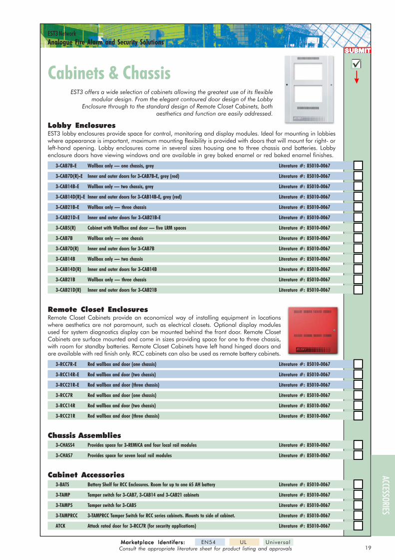
19Marketplace Identifers:Marketplace Identifers:Marketplace Identifers:Marketplace Identifers:Marketplace Identifers: EN54 UL Universal
Consult the appropriate literature sheet for product listing and approvals
EST3 NetworkAnalogue Fire Alarm and Security Solutions
ACCESSORIES
SUBMITSUBMITSUBMITSUBMITSUBMIT
EST3 offers a wide selection of cabinets allowing the greatest use of its flexiblemodular design. From the elegant contoured door design of the Lobby
Enclosure through to the standard design of Remote Closet Cabinets, bothaesthetics and function are easily addressed.
Lobby EnclosuresEST3 lobby enclosures provide space for control, monitoring and display modules. Ideal for mounting in lobbieswhere appearance is important, maximum mounting flexibility is provided with doors that will mount for right- orleft-hand opening. Lobby enclosures come in several sizes housing one to three chassis and batteries. Lobbyenclosure doors have viewing windows and are available in grey baked enamel or red baked enamel finishes.
3-CAB7B-E Wallbox only — one chassis, grey Literature #: 85010-0067
3-CAB7D(R)-E Inner and outer doors for 3-CAB7B-E, grey (red) Literature #: 85010-0067
3-CAB14B-E Wallbox only — two chassis, grey Literature #: 85010-0067
3-CAB14D(R)-E Inner and outer doors for 3-CAB14B-E, grey (red) Literature #: 85010-0067
3-CAB21B-E Wallbox only — three chassis Literature #: 85010-0067
3-CAB21D-E Inner and outer doors for 3-CAB21B-E Literature #: 85010-0067
3-CAB5(R) Cabinet with Wallbox and door — five LRM spaces Literature #: 85010-0067
3-CAB7B Wallbox only — one chassis Literature #: 85010-0067
3-CAB7D(R) Inner and outer doors for 3-CAB7B Literature #: 85010-0067
3-CAB14B Wallbox only — two chassis Literature #: 85010-0067
3-CAB14D(R) Inner and outer doors for 3-CAB14B Literature #: 85010-0067
3-CAB21B Wallbox only — three chassis Literature #: 85010-0067
3-CAB21D(R) Inner and outer doors for 3-CAB21B Literature #: 85010-0067
Remote Closet EnclosuresRemote Closet Cabinets provide an economical way of installing equipment in locationswhere aesthetics are not paramount, such as electrical closets. Optional display modulesused for system diagnostics display can be mounted behind the front door. Remote ClosetCabinets are surface mounted and come in sizes providing space for one to three chassis,with room for standby batteries. Remote Closet Cabinets have left hand hinged doors andare available with red finish only. RCC cabinets can also be used as remote battery cabinets.
3-RCC7R-E Red wallbox and door (one chassis) Literature #: 85010-0067
3-RCC14R-E Red wallbox and door (two chassis) Literature #: 85010-0067
3-RCC21R-E Red wallbox and door (three chassis) Literature #: 85010-0067
3-RCC7R Red wallbox and door (one chassis) Literature #: 85010-0067
3-RCC14R Red wallbox and door (two chassis) Literature #: 85010-0067
3-RCC21R Red wallbox and door (three chassis) Literature #: 85010-0067
Chassis Assemblies3-CHASS4 Provides space for 3-REMICA and four local rail modules Literature #: 85010-0067
3-CHAS7 Provides space for seven local rail modules Literature #: 85010-0067
Cabinet Accessories3-BATS Battery Shelf for RCC Enclosures. Room for up to one 65 AH battery Literature #: 85010-0067
3-TAMP Tamper switch for 3-CAB7, 3-CAB14 and 3-CAB21 cabinets Literature #: 85010-0067
3-TAMP5 Tamper switch for 3-CAB5 Literature #: 85010-0067
3-TAMPRCC 3-TAMPRCC Tamper Switch for RCC series cabinets. Mounts to side of cabinet. Literature #: 85010-0067
ATCK Attack rated door for 3-RCC7R (for security applications) Literature #: 85010-0067
Cabinets & ChassisCabinets & Chassis

20Marketplace Identi fers:Marketplace Identi fers:Marketplace Identi fers:Marketplace Identi fers:Marketplace Identi fers: EN54 UL Universal
Consult the appropriate literature sheet for product listing and approvals
EST3 NetworkAnalogue Fire Alarm and Security Solutions
SECU
RITY
/ACC
ESS
AUDI
ORE
MOTE
REPE
ATER
SDI
SPLA
YLO
CAL R
AIL M
ODUL
ES
SUBMITSUBMITSUBMITSUBMITSUBMIT
Main Panel Power Supplies
EST3 Power supplies consist of two assemblies, a high efficiency switch modepower supply card and a power supply monitor module. Up to four powersupplies may be combined in a single enclosure to provide up to 28 amps ofavailable current. Battery backup is provided using from one to four sets ofbatteries, depending on standby power requirements to support up to 260 AHbatteries
The power supply comesin two styles: a primarysupply and a boostersupply. Each power sup-ply produces 7 amps of
filtered and regulated 24 VDC. The primary power supplyprovides the system with battery charging and voltage regu-lation. The booster supplies work in concert with the pri-mary supply and are available with or without battery charg-ing capability. Software configuration configures the bat-tery changing circuits for either 10-24 AH batteries or 30 –65 AH batteries and controls the high/low charge rate.
EST3 power supplies individually monitor batteries for load deficiencies, short circuits, and insufficient voltagelevels and report trouble back to the 3-CPU3. The 3-LCD displays any troubles and the power supply’saddress, a specific trouble code, and a text message describing the specific trouble.
3-PPS/M Primary Power Supply w/ local rail module 120V 50/60 Hz Literature #: 85010-0059
3-BPS/M Booster Power Supply w/ local rail module 120V 50/60 Hz Literature #: 85010-0059
3-BBC/M Booster/Charger Supply w/local rail module 120V 50/60Hz Literature #: 85010-0059
3-PPS/M-230 Primary Power Supply w/ local rail module 230V 50/60 Hz Literature #: 85010-0059
3-BPS/M-230 Booster Power Supply w/ local rail module 230V 50/60 Hz Literature #: 85010-0059
3-BBC/M-230 Booster/Charger Supply w/local rail module 230V 50/60Hz Literature #: 85010-0059
3-PPS/M-230-E Primary Power Supply w/local rail module 230V 50 Hz, EN-54 Certified, CE Literature #: 85010-0059
3-BPS/M-230-E Booster Power Supply w/local rail module 230V 50 Hz, EN-54 Certified, CE Literature #: 85010-0059
3-BBC/M-230-E Booster/Charger Supply w/local rail module 230V 50/60Hz Literature #: 85010-0059
3-BBCMON Booster/Charger Monitor Module with charger capability (used to upgrade BPS to BBC) Literature #: 85010-0059
3-BBCMON-E Booster/Charger Monitor Module with charger capability (used to upgrade BPS to BBC) Literature #: 85010-0059
Power Suppliesower SuppliesEST3 power supplies use a unique paralleling arrangementthat ensures optimization of each supply’s full capacity. Eachpower supply supports up to a 7 amp load. With four supplies,28 Amps of current is available per cabinet as is battery charg-ing capacity of up to 260 Amp-Hours.
MasterPowerSupply
BoosterPowerSupply
24Vdc *2 x 3.5A
24Vdc *2 x 3.5A
124 3
UtilityPower
PowerTo Rail
AuxillaryPowerTakeoff2 x 3.5A
MasterPower SupplyMonitor Module
PowerSupplyMonitoring
Rails
124 3
AuxillaryPowerTakeoff2 x 3.5A
24Vdc *2 x 3.5A
24Vdc *2 x 3.5A
124 3
AuxillaryPowerTakeoff2 x 3.5A
BoosterPower SupplyMonitor Module
Rails
124 3
AuxillaryPowerTakeoff2 x 3.5A
BoosterPowerSupply
BoosterPowerSupply
J8
J9
J10
J11
J8
J9
J10
J11
PowerSupply
LRM
Battery Distribution Unit
The 3-BTSEN consists of a circuit breaker and copper bus bars mounted on a sheetmetal bracket. The unit provides a backup battery bus for supplying backup powerto multiple power supplies fed by a common battery. The 3-BTSEN features a 50Amp circuit breaker to protect the backup battery. The 3-BTSEN mounts in the BC-1Battery cabinet or any EST3 “RCC” series enclosure.
3-BTSEN-E Battery Distribution Unit w/temperature probe Literature #: 85010-0111
3-BTSEN Battery Distribution Unit Literature #: 85010-0111
12Volts12Volts
RedBlack
Backup Battery Bus Wiring
To Booster 2and Booster 3
To Driverand Booster 1
MonitorMonitorMonitorMonitorMonitorModuleModuleModuleModuleModule
PowerPowerPowerPowerPowerSupplySupplySupplySupplySupply
ACCE
SSOR
IES

21Marketplace Identifers:Marketplace Identifers:Marketplace Identifers:Marketplace Identifers:Marketplace Identifers: EN54 UL Universal
Consult the appropriate literature sheet for product listing and approvals
EST3 NetworkAnalogue Fire Alarm and Security Solutions
SUBMITSUBMITSUBMITSUBMITSUBMIT
Remote Booster Power Supply
The Remote Booster Power Supply is a self-contained 24 Vdcpower supply designed to augment fire alarm audible andvisual power requirements. The booster contains all of thenecessary circuits to monitor and charge batteries, controland supervise four spur (Class B) or two loop (Class A) soundercircuits and monitor two controlling inputs from externalsources.
Simple switch selection provides a wide variety of operationalconfigurations. Each remote booster power supply is suppliedwith its own enclosure providing ample space for additionalinterface modules and battery compartment. The BPS is avail-able in either a 6.5 or 10 amp version @ 24 Vdc.
The Remote Booster Power Supply provides additional power for audible and visual devices when constrainedby system capacity or site application. Fault conditions detected by the BPS will open the main panel’s soundercircuit. This initiates a trouble condition and eliminates the need to wire a separate trouble contact back to thecontrol panel. During alarm condition, detected faults are overridden and the main panel’s default configura-tion is restored.
The BPS’s default output configuration is continuous 24 Vdc on all NACs. This output is typically used to drivevisual devices.
BPS notification appliance circuits easily configure for any one ofthree signalling rates: 120 SPM, 3-3-3 temporal, or continuous.This makes the BPS ideal for applications requiring signalling ratesnot available from the main panel. It also allows independent setupof a notification appliance circuit without interfering with the mainpanel and its initiating circuits.
In addition to the three generated signal rates, the BPS can also beconfigured to follow the signal rate of the main panel’s notificationappliance circuit. This allows seamless expansion of existing NACs.
BPS6 Booster Power Supply, 6.5A, 120V Literature #: 85005-0107
BPS6220 Booster Power Supply, 6.5A, 220V Literature #: 85005-0107
BPS10 Booster Power Supply, 10A, 110V Literature #: 85005-0107
BPS10220 Booster Power Supply, 10A, 220V Literature #: 85005-0107
260006 UL Listed Fuse Holder c/w 4 Amp Fuse Literature #: 85005-0107
BPS AssemblyBPS AssemblyBPS AssemblyBPS AssemblyBPS Assembly
Backbox
Booster Power Supply
Battery
(non-power limited)
Route AC supplythrough theseknockouts only
Battery
Battery wiring(non-powerlimited)
power limitedwiring area
L N G + BATTERY -
SW
1
NC
TR
OU
BL
EC
OM
NO
OU
TSE
NS
E2
CO
MIN
OU
TSE
NS
E1
CO
MIN
-N
AC
4+-
NA
C3+
-N
AC
2+-
NA
C1+
NA
C1
NA
C2
NA
C3
NA
C4
BA
T
GN
D
AB RATEAC AUX1 2 3 4 5 6 7 8 9 10 11 12S1 S2
P3
P2
SW1
1
P4
P1
SignatureModule
SignatureModule
SignatureModule
Batteries and Battery CabinetsLiterature #: 85010-0127
12 Volt Batteries 12V4A (4.5 Ah) 12V6A5 (7.2 Ah) 12V10A (11 Ah)
12V17A (17 Ah) 12V24A (26 Ah) 12V40A (40 Ah) 12V50A (50 Ah) 12V55A (55 Ah) 12V65A (65 Ah)
6 Volt Batteries 6V8A (8 Ah) 6V10A (12 Ah)
Battery Cabinets BC-1 (holds up to two 40 Ah batteries) 3-RCC used as large battery enclosure (holds up to two 65 Ah batteries)
Wiring: Single Booster on SounderWiring: Single Booster on SounderWiring: Single Booster on SounderWiring: Single Booster on SounderWiring: Single Booster on SounderC i r cu i tC i r cu i tC i r cu i tC i r cu i tC i r cu i t
(See literature sheet for more wiring options)
Fire AlarmControl Panel
NAC Circuit
NAC Circuit
NAC output #1
To next signalingdevice, booster, orEOL resistor
NAC output #2NAC output #3NAC output #4
Sen
se
1In
put
Sen
se
2In
put
Booster PowerSupply
ACCESSORIES
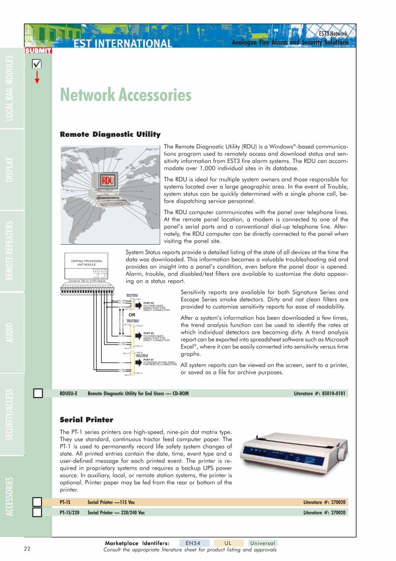
22Marketplace Identifers:Marketplace Identifers:Marketplace Identifers:Marketplace Identifers:Marketplace Identifers: EN54 UL Universal
Consult the appropriate literature sheet for product listing and approvals
EST3 NetworkAnalogue Fire Alarm and Security Solutions
SUBMITSUBMITSUBMITSUBMITSUBMIT
Serial Printer
The PT-1 series printers are high-speed, nine-pin dot matrix type.They use standard, continuous tractor feed computer paper. ThePT-1 is used to permanently record life safety system changes ofstate. All printed entries contain the date, time, event type and auser-defined message for each printed event. The printer is re-quired in proprietary systems and requires a backup UPS powersource. In auxiliary, local, or remote station systems, the printer isoptional. Printer paper may be fed from the rear or bottom of theprinter.
PT-1S Serial Printer —115 Vac Literature #: 270020
PT-1S/220 Serial Printer — 220/240 Vac Literature #: 270020
Remote Diagnostic Utility
The Remote Diagnostic Utility (RDU) is a Windows®-based communica-tions program used to remotely access and download status and sen-sitivity information from EST3 fire alarm systems. The RDU can accom-modate over 1,000 individual sites in its database.
The RDU is ideal for multiple system owners and those responsible forsystems located over a large geographic area. In the event of Trouble,system status can be quickly determined with a single phone call, be-fore dispatching service personnel.
The RDU computer communicates with the panel over telephone lines.At the remote panel location, a modem is connected to one of thepanel’s serial ports and a conventional dial-up telephone line. Alter-nately, the RDU computer can be directly connected to the panel whenvisiting the panel site.
System Status reports provide a detailed listing of the state of all devices at the time thedata was downloaded. This information becomes a valuable troubleshooting aid andprovides an insight into a panel’s condition, even before the panel door is opened.Alarm, trouble, and disabled/test filters are available to customize the data appear-ing on a status report.
Sensitivity reports are available for both Signature Series andEscape Series smoke detectors. Dirty and not clean filters areprovided to customize sensitivity reports for ease of readability.
After a system’s information has been downloaded a few times,the trend analysis function can be used to identify the rates atwhich individual detectors are becoming dirty. A trend analysisreport can be exported into spreadsheet software such as MicrosoftExcel®, where it can be easily converted into sensitivity versus timegraphs.
All system reports can be viewed on the screen, sent to a printer,or saved as a file for archive purposes.
RDUEU-E Remote Diagnostic Utility for End Users — CD-ROM Literature #: 85010-0101
CENTRAL PROCESSING
UNIT MODULE
11 112 214 413 315 516 617 718 819 920 10
OR
PIN 1
PIN 14
PIN 13PIN 25
PIN 1
PIN 9
(2) TXD
(2) RXD
Connect to TB2 on 3-CPU Module
(3) RXD
(3) TXD
(7) COM
(5) COM
DB25 FEMALE(REAR VIEW)
DB9 FEMALE(REAR VIEW)
PL
UG
PIN
#
PIN
FU
NC
TIO
N
TO COMPUTER'SSERIAL PORT FORDIRECT CONNECTION
TO COMPUTER'SSERIAL PORT FORDIRECT CONNECTION
TO MODEM ON FIRE PANELFOR REMOTE CONNECTION
PORT #2
PORT #2
PORT #1
PIN 1PIN 14
PIN 13PIN 25
(2) TXD(3) RXD
(7) COM
DB25 FEMALE(REAR VIEW)
R T R CX X T O1 1 S M
1 18 7 6 5
R T R CX X T O2 2 S M
2 24 3 2 1
Network AccessoriesNetwork Accessories
SECU
RITY
/ACC
ESS
AUDI
ORE
MOTE
REPE
ATER
SDI
SPLA
YLO
CAL R
AIL M
ODUL
ESAC
CESS
ORIES
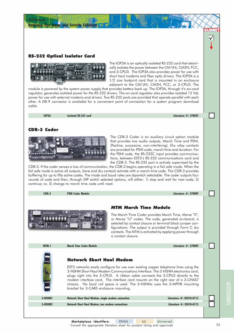
23Marketplace Identifers:Marketplace Identifers:Marketplace Identifers:Marketplace Identifers:Marketplace Identifers: EN54 UL Universal
Consult the appropriate literature sheet for product listing and approvals
EST3 NetworkAnalogue Fire Alarm and Security Solutions
SUBMITSUBMITSUBMITSUBMITSUBMIT
RS-232 Optical Isolator Card
The IOP3A is an optically isolated RS-232 card that electri-cally isolates the power between the CM1(N), CM2N, FCC,and 3-CPU3. The IOP3A also provides power for use withshort haul modems and fiber optic drivers. The IOP3A is a1/2 size footprint card that is mounted in an enclosureadjacent to the CM1(N), CM2N, FCC, or 3-CPU3. The
module is powered by the system power supply that provides battery back up. The IOP3A, through it’s on-cardregulator, generates isolated power for the RS-232 drivers. The on-card regulator also provides isolated 12 Vdcpower for use with external modems and drivers. Two RS-232 ports are provided that operate parallel with eachother. A DB-9 connector is available for a convenient point of connection for a system program downloadcable.
IOP3A Isolated RS-232 card Literature #: 270039
CDR-3 Coder
The CDR-3 Coder is an auxiliary circuit option modulethat provides two audio outputs, March Time and PSNI,(Positive, successive, non-interfering). Dry relay contactsare provided for PSNI code, march time and duration. Forthe PSNI code, the RS-232C input provides communica-tions, between EST3’s RS-232 communications card andthe CDR-3. The RS-232 port is actively supervised by the
CDR-3. If the coder senses a loss of communication, the CDR-3 begins operating in a fail safe mode. When thefail safe mode is active all outputs, (tone and dry contact) activate with a march time code. The CDR-3 providesbuffering for up to fifty active codes. The mode and baud rates are dipswitch selectable. The coder outputs fourrounds of code and then, through DIP switch selected options, will either: 1) stop and wait for next code; 2)continue; or, 3) change to march time code until reset.
CDR-3 PSNI Coder Module Literature #: 270009
MTM March Time Module
The March Time Coder provides March Time, Morse “S”,or Morse “U” codes. The code, generated on-board, isselected by contact closure or terminal block jumper con-figurations. The output is provided through Form C drycontacts. The MTM is activated by applying power througha contact closure.
MTM-1 March Time Coder Module Literature #: 270009
Network Short Haul Modem
EST3 networks easily configure for use over existing copper telephone lines using the3-NSHM Short Haul Modem Communications Interface. The 3-NSHM electronics card,plugs right into the 3-CPU3. A ribbon cable connects the 3-CPU3 directly to themodem interface card. The interface card mounts on the right rear of a 3-CHAS7chassis. No local rail space is used. The 3-NSHMs uses the 3-MPFIB mountingbracket for 3-CAB5 enclosure mounting.
3-NSHM1 Network Short Haul Modem, single modem connection Literature #: 85010-0113
3-NSHM2 Network Short Haul Modem, two modem connections Literature #: 85010-0113
ACCESSORIES
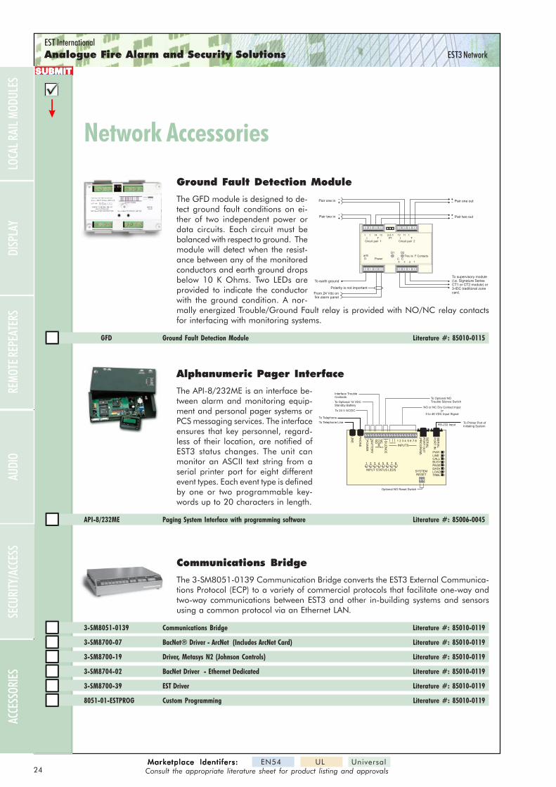
EST InternationalAnalogue Fire Alarm and Security Solutions EST3 Network
SUBMITSUBMITSUBMITSUBMITSUBMIT
Ground Fault Detection Module
The GFD module is designed to de-tect ground fault conditions on ei-ther of two independent power ordata circuits. Each circuit must bebalanced with respect to ground. Themodule will detect when the resist-ance between any of the monitoredconductors and earth ground dropsbelow 10 K Ohms. Two LEDs areprovided to indicate the conductorwith the ground condition. A nor-mally energized Trouble/Ground Fault relay is provided with NO/NC relay contactsfor interfacing with monitoring systems.
GFD Ground Fault Detection Module Literature #: 85010-0115
From 24 Vdc onfire alarm panel
To earth ground
Polarity is not important
Pair one in Pair one out
Pair two in Pair two out
To supervisory module(i.e. Signature SeriesCT1 or CT2 module) or3-IDC traditional zonecard.
++
++
arthD Power
Circuit pair 1 Circuit pair 2I IP1
D1 D2
T3-2-1
T
Trou le F ContactsC C
13
1
1
3
1114
2
11
4
12
Alphanumeric Pager Interface
The API-8/232ME is an interface be-tween alarm and monitoring equip-ment and personal pager systems orPCS messaging services. The interfaceensures that key personnel, regard-less of their location, are notified ofEST3 status changes. The unit canmonitor an ASCII text string from aserial printer port for eight differentevent types. Each event type is definedby one or two programmable key-words up to 20 characters in length.
API-8/232ME Paging System Interface with programming software Literature #: 85006-0045
LIN
E BA
TT
ER
Y
PO
WE
R
~ ~COMMON
1 2 3 4 5 6 7 8
PH
ON
E
SIL
EN
CE
INPUTSTROUBLE
SYSTEMRESET
SE
RIA
LP
OR
TIN
SE
RIA
LP
OR
TO
UT
(PR
OG
RA
M)
NC
CO
MN
O
INPUT STATUS LEDS
1 2 3 4 5 6 7 8
PWRLINECALLBUSYPAGEDATALOADTRBL
To Telephone Line
To Telephone
Interface TroubleContacts
To Optional 12 VDCStandby Battery
To Printer Port ofInitiating System
NO or NC Dry Contact Inputor
0 to 48 VDC Input Signal
RS-232 Input
To 24 V AC/DC
Optional NO Reset Switch
To Optional NOTrouble Silence Switch
Network AccessoriesNetwork Accessories
Communications Bridge
The 3-SM8051-0139 Communication Bridge converts the EST3 External Communica-tions Protocol (ECP) to a variety of commercial protocols that facilitate one-way andtwo-way communications between EST3 and other in-building systems and sensorsusing a common protocol via an Ethernet LAN.
3-SM8051-0139 Communications Bridge Literature #: 85010-0119
3-SM8700-07 BacNet® Driver - ArcNet (Includes ArcNet Card) Literature #: 85010-0119
3-SM8700-19 Driver, Metasys N2 (Johnson Controls) Literature #: 85010-0119
3-SM8704-02 BacNet Driver - Ethernet Dedicated Literature #: 85010-0119
3-SM8700-39 EST Driver Literature #: 85010-0119
8051-01-ESTPROG Custom Programming Literature #: 85010-0119
SECU
RITY
/ACC
ESS
AUDI
ORE
MOTE
REPE
ATER
SDI
SPLA
YLO
CAL R
AIL M
ODUL
ESAC
CESS
ORIES
24Marketplace Identifers:Marketplace Identifers:Marketplace Identifers:Marketplace Identifers:Marketplace Identifers: EN54 UL Universal
Consult the appropriate literature sheet for product listing and approvals


Headquar tersHeadquar tersHeadquar tersHeadquar tersHeadquar ters201 City Centre Dr., Ste 500, Mississauga, ON L5B 2T4 CANADAPhone: (001) 905-270-1711; Fax: (001) 905-270-9553;Web: www.estinternational.comE-mail: [email protected]
EuropeEu ropeEu ropeEu ropeEu ropeRudford Estate, Ford Aerodrome, Arundel BN18 0BE, UK;Phone: +44-1903-711 440; Fax:+44-1903-711 448Web: www.estinternational.com
Submittal Guide: EST3 Life Safety and Security Solutions
This Submittal Guide is a concise summary of EST3
control, display, communications, and security
components. It is intended as a supplement to product
literature. Information on field devices, including
detectors, sounders, callpoints and more, can be found
in Submittal Guide: Field Devices. To obtain copies of this
book, please order part number 85010-0138.
85010-0136