EST DATA ACQUISITION AND ANALYSIS
91
EST DATA ACQUISITION AND ANALYSIS
Transcript of EST DATA ACQUISITION AND ANALYSIS
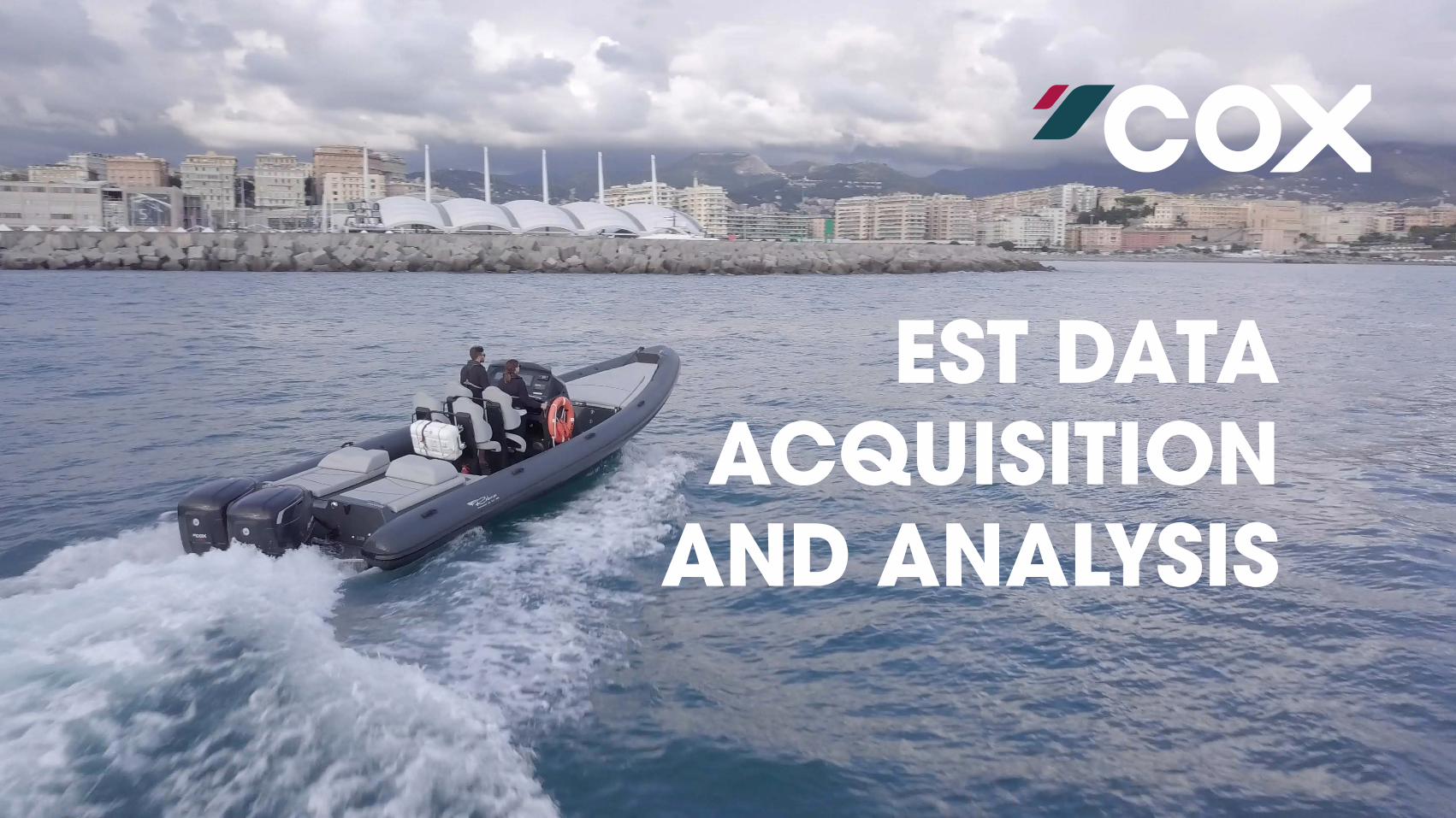
EST DATA ACQUISITION
AND ANALYSIS

OBJECTIVES

OBJECTIVES
1 Primary objective of this training is to understand: � How to capture accurate and appropriate EST data
� Where the data is measured from on the outboard
� What the data is telling the user about the operation of the outboard
� How the available data can be used to help define a product issue
2 Secondary objective:
� Understand the requirement to supply sufficient data to Cox to aid in the diagnosis of various problem issues

WHAT IS EST DATA?
EST data is a record of the various outboard parameters during a defined period.
In total, there are 26 different parameters that are recorded in a EST data file.
These parameters have been selected by Cox as the most critical when understanding outboard performance.
Each row in the .CSV file represents a snap shot of these parameters every 0.0125 seconds (80Hz).

IMPORTANCE OF EST DATA
EST data is important as it captures the performance characteristics of the outboard(s) and aids in troubleshooting any issues that may be occurring.
These issues can be as simple as identifying an air pressure boost leak at high rpm which may not be detectable by the operator whilst running the engine.
It is highly advisable to collect as much data as possible for an outboard and assess it to understand how the outboard is currently performing. Comparing the data to the initial data logs taken at the commissioning process can show if there is any degradation in outboard performance.
Data is key when diagnosing an issue as it can aid in pin-pointing the technician to the exact issue and minimise the amount of tool time involved.

HOW TO OBTAIN DATA FROM EST

CONNECTING TO OUTBOARD DIAGNOSTIC
To connect to the vessel diagnostic port using the Kvaser dongle, see video link:
How To Connect Vessel Diagnostic Port to Computer

OPERATING EST AND LOGGING DATA
1 EST software can be downloaded from the Cox Portal.
2 A license is required which is supplied by Cox.
� A license is provided for each dealer.
� Additional licenses can be purchased.
3 See video link below that shows how to use the EST software and create a logged file: EST VIDEO GUIDE

DEFINING MULTIPLE LOGS
1 Keep a record of the different logs and the different conditions between logs.
� e.g. part changes, ambient and sea conditions
2 Define what was the objective of the log.
3 Define in a table format as per below.
4 This is critical when supplying multiple data files to Cox to ensure we understand what you are investigating.
5 This table should be uploaded to the Salesforce case when uploading the EST files.
LOG NUMBER TIME OF LOG OBJECTIVE OF LOG PARAMETER CHANGES LOG NAME
1 09:25 500rpm interval step change commissioning run Base set up CX00179AH20210203501_2021-05-01T14-51-55Z_SDYST_01
2 10:06 Investigate impact of smaller propeller size Propeller changed to 15x21” 3 blade CX00179AH20210203501_2021-05-01T15-22-14Z_SDYST_02
3 10:45 Continuation of small propeller size Sea state is reduced CX00179AH20210203501_2021-05-01T15-25-47Z_SDYST_03
4 10:56 As above As above CX00179AH20210203501_2021-05-01T15-32-21Z_SDYST_01

SUBMITTING EST DATA TO COX
1 To submit the EST data files to Cox, it is best to upload the files to the appropriate Enquiry and Technical Assistance case on the Cox Portal.
2 If a case has yet to be created for the issue that you are experiencing, then create a new case and upload the EST files.
� Email software does not recognise the .JSON file format and will reject the files.
� .CSV files may be too large to send via email due to email size limits.
NOTEEmailing EST data files is not considered appropriate.

STANDARD COX TESTS FOR DATA ACQUISITION

COX STANDARD TESTS
1 Below is a list of standard tests that Cox expects to be issued when commissioning a vessel and to aid in problem diagnostic activities
� Steady state test
� Slow speed transient test
� High speed transient test
� System prove out tests
2 It is important to collect this data when the vessel is commissioned, as all subsequent data logs can be compared against it:
� Highlight any degradation in outboard performance
� Identify a problem
� Ensure any repair or rework activities do not impact the performance of the outboard

NAMING CONVENTION
CX00179AH20210121102_2021-03-01T13-51-01Z_XXXXX_##Powerhead Serial No.
Automatically Generated Manually Added
Log Date
Log Time
Test Name
Log Sequence Number

STEADY STATE TEST
PROCESS
1 Gradually increase engine speed from 1000 – 4000 rpm in 500 rpm intervals
2 At each engine speed, maintain engine speed steady for 20 seconds
WHY
1 Develop a steady state data set to capture how the engine performs at different engine speeds
2 Allow comparisons to be made to pin-point specific issues
� i.e. identify a boost leak above 3000 rpm
NAMING
1 When saving the file, apply the following to the end of the file name:
CX00179AH20210121102_2021-03-01T13-51-01Z_SDYST_01
0
500
1000
1500
2000
2500
3000
3500
4000
4500
0 20 40 60 80 100 120 140
Engi
ne S
peed
(rpm
)
Time (seconds)
STEADY STATE TEST

SLOW SPEED TRANSIENT TEST
PROCESS
1 A controlled increase in engine speed from 1000 – 2000 – 3000 rpm
2 Increase engine speed over a 5 second interval
3 Use a smooth progressive throttle control
4 At each speed point, maintain engine speed steady for 30 seconds
WHY
1 Define a nominal usage
2 Ensure that outboard parameter responses are as intended
3 There is a smooth transition between engine speeds with no “hiccups”
NAMING
1 When saving the file, apply the following to the end of the file name: CX00179AH20210121102_2021-03-01T13-51-01Z_SLOTT_01
0
500
1000
1500
2000
2500
3000
3500
0 40 80 120 160 200 240 280
Engi
ne S
peed
(rpm
)
Time (seconds)
SLOW SPEED TRANSIENT TEST
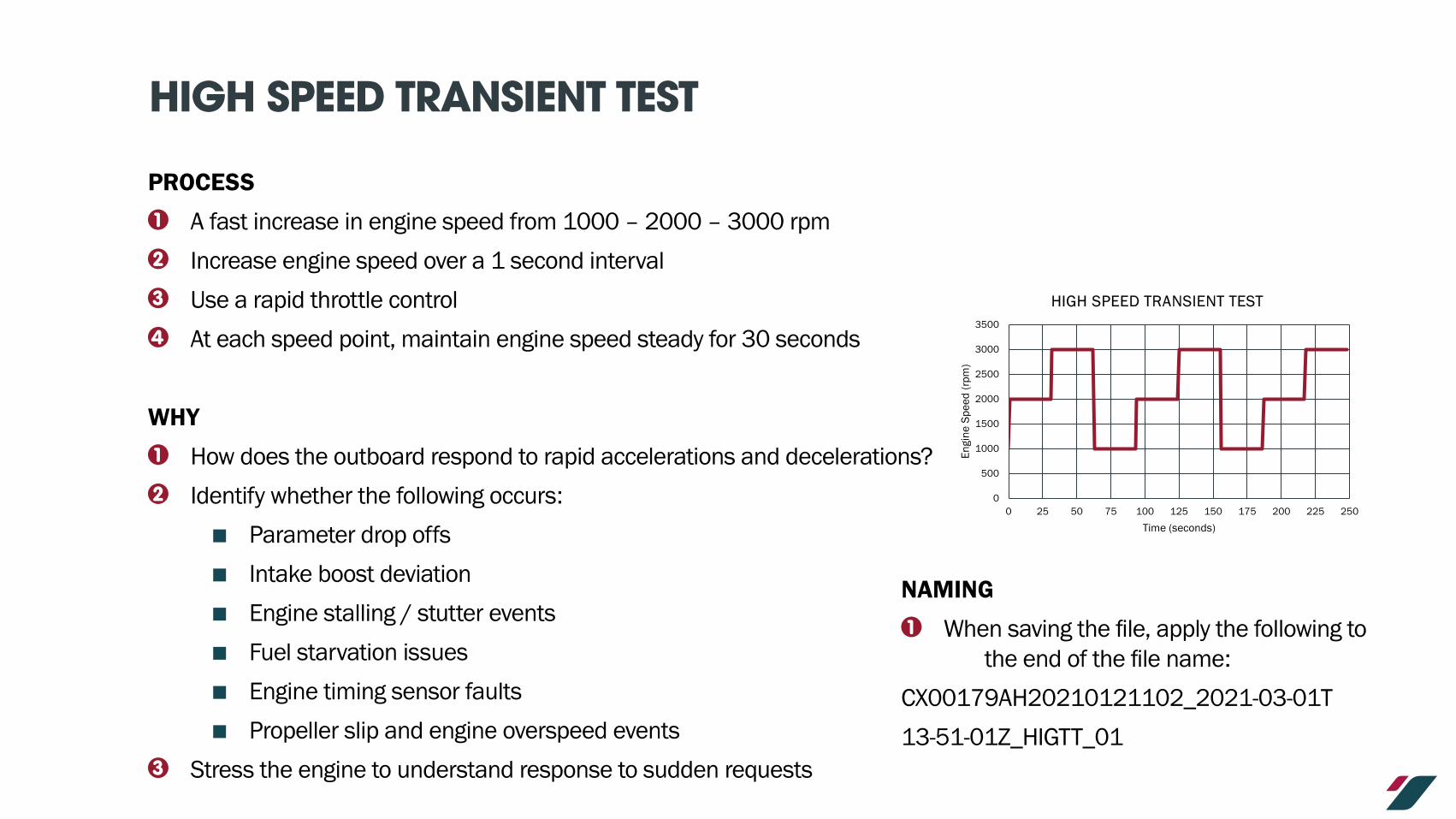
HIGH SPEED TRANSIENT TEST
PROCESS
1 A fast increase in engine speed from 1000 – 2000 – 3000 rpm
2 Increase engine speed over a 1 second interval
3 Use a rapid throttle control
4 At each speed point, maintain engine speed steady for 30 seconds
WHY
1 How does the outboard respond to rapid accelerations and decelerations?
2 Identify whether the following occurs:
� Parameter drop offs
� Intake boost deviation
� Engine stalling / stutter events
� Fuel starvation issues
� Engine timing sensor faults
� Propeller slip and engine overspeed events
3 Stress the engine to understand response to sudden requests
NAMING
1 When saving the file, apply the following to the end of the file name:
CX00179AH20210121102_2021-03-01T
13-51-01Z_HIGTT_01
0
500
1000
1500
2000
2500
3000
3500
0 25 50 75 100 125 150 175 200 225 250
Engi
ne S
peed
(rpm
)
Time (seconds)
HIGH SPEED TRANSIENT TEST
SYSTEM PROVE OUT TESTS
1 Prove that the outboard inhibits work
� Reverse limit – is set appropriately
� Trim limit – is set appropriately
2 Outboards do not start when throttle levers are in detents
3 CoastKey functionality:
� Will kill engines when CoastKey fob is dunked in water
� As per a MOB event, restart engines using CoastKey panel
OUTBOARD SENSOR POSITIONS

OUTBOARD SENSOR & ACTUATOR DIAGRAM
LOCATION DESCRIPTION QUANTITY PART NUMBER
A1 TMAP Sensor 1 020690
A2 Crankshaft Position Sensor 1 033451
A3 Camshaft Position Sensor 1 026939
A4i Pressure Sensor: Oil Filter Housing 1 028018
A4ii Pressure Sensor: Oil Cylinder Head 1 028018
A4iii Pressure Sensor: Powerhead Fuel Filter Housing 1 028018
A5 Coolant Temperature Sensor 2 028756
A6 Oil Temperature Sensor 1 028019
A7 Cylinder Head Temperature Sensor 2 030170
A8 Turbo Boost Actuator Valve 2 034995
A9 Mass Air Flow Sensor 2 033616
A10 GSA Motor 1 029920
A11 PDM 1 033600
A12 ECU 1 027294
A13 Fuel Rail with High Pressure Sensor 1 032392
A14 Fuel Rail with High Pressure Valve 1 032395
A15 Fuel Injectors 8 032728
A16 Glow Plugs 8 022890
A17 Vessel Fuel Lift Pump Water In Fuel Sensor 1 034278
A18 HP Fuel Pump with Fuel Temperature Sensor 1 026192
BANK 2 - PORT SIDE BANK 1 - STARBOARD SIDE
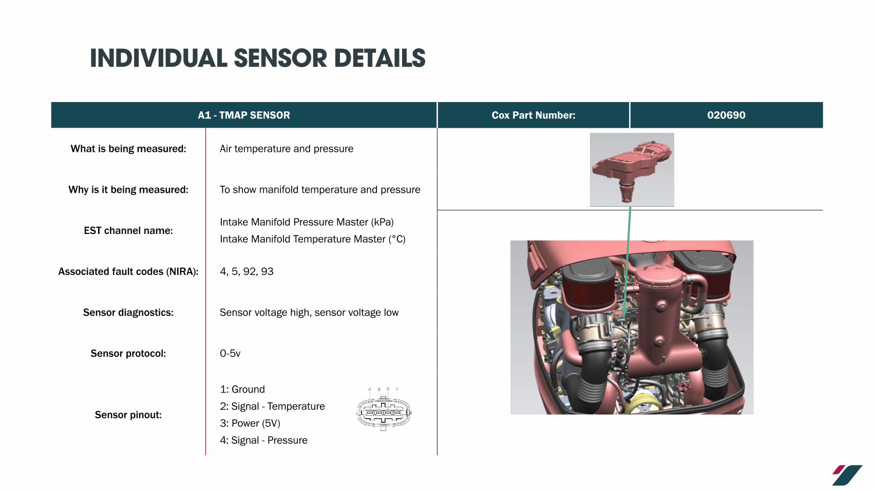
INDIVIDUAL SENSOR DETAILS
A1 - TMAP SENSOR Cox Part Number: 020690
What is being measured: Air temperature and pressure
Why is it being measured: To show manifold temperature and pressure
EST channel name:Intake Manifold Pressure Master (kPa)
Intake Manifold Temperature Master (°C)
Associated fault codes (NIRA): 4, 5, 92, 93
Sensor diagnostics: Sensor voltage high, sensor voltage low
Sensor protocol: 0-5v
Sensor pinout:
1: Ground
2: Signal - Temperature
3: Power (5V)
4: Signal - Pressure

INDIVIDUAL SENSOR DETAILS
A2 - CRANKSHAFT POSITION SENSOR Cox Part Number: 033451
What is being measured: Engine speed
Why is it being measured: To show engine speed and enable control of the engine
EST channel name: Engine Speed Master ()
Associated fault codes (NIRA): 124, 125
Sensor diagnostics: Unstable crank tooth signal, no crank tooth signal
Sensor protocol: N/A
Sensor pinout:
1: Power – 5V
2: Signal A
3: Signal B
4: Ground

INDIVIDUAL SENSOR DETAILS
A3 - CAMSHAFT POSITION SENSOR Cox Part Number: 026939
What is being measured: Camshaft position
Why is it being measured: Enables engine control
EST channel name: N/A
Associated fault codes (NIRA): 126, 127
Sensor diagnostics:Camshaft position signal not detected, Camshaft position signal not detected when expected
Sensor protocol:
Sensor pinout:
1: Power – 5V
2: Signal
3: Ground

INDIVIDUAL SENSOR DETAILS
A4i - PRESSURE SENSOR: OIL FILTER HOUSING Cox Part Number: 028018
What is being measured: Oil pressure in the filter housing
Why is it being measured: Monitor engine oil supply
EST channel name: Engine Oil Filter Outlet Pressure Master (kPa)
Associated fault codes (NIRA): 6, 7, 149, 198, 199
Sensor diagnostics: Sensor voltage high, sensor voltage low, pressure low, pressure high
Sensor protocol: 0-5V
Sensor pinout:
Pin 1: Power – 5V
Pin 2: Ground
Pin 3: Signal

INDIVIDUAL SENSOR DETAILS
A4ii – PRESSURE SENSOR: OIL CYLINDER HEAD Cox Part Number: 028018
What is being measured: Cylinder head oil pressure
Why is it being measured: Monitor engine oil supply
EST channel name: Oil Pressure Master (kPa)
Associated fault codes (NIRA): 8, 9, 149, 198, 199
Sensor diagnostics: Sensor voltage high, sensor voltage low, pressure low, pressure high
Sensor protocol: 0-5V
Sensor pinout:
Pin 1: Power – 5V
Pin 2: Ground
Pin 3: Signal

INDIVIDUAL SENSOR DETAILS
A4iii – PRESSURE SENSOR: POWERHEAD FUEL FILTER HOUSING Cox Part Number: 028018
What is being measured: Fuel filter pressure
Why is it being measured: Monitor fuel supply to high pressure fuel pump
EST channel name: Fuel Filter Pressure Master (kPa)
Associated fault codes (NIRA): 2, 3, 200, 201
Sensor diagnostics: Sensor voltage high, Sensor voltage low, Fuel filter pressure low
Sensor protocol: 0-5V
Sensor pinout:
Pin 1: Power – 5V
Pin 2: Ground
Pin 3: Signal

INDIVIDUAL SENSOR DETAILS
A5 – COOLANT TEMPERATURE SENSOR Cox Part Number: 028756
What is being measured: Engine coolant temperature
Why is it being measured: Monitor engine temperature
EST channel name:
Port: Coolant Head Temperature Sensor #1 Master (°C)
Starboard: Coolant Head Temperature Sensor #2 Master (°C)
Associated fault codes (NIRA): 94, 95, 96, 97, 181, 182, 183
Sensor diagnostics:Sensor voltage high/low, coolant temperature high, coolant temperature unbalanced
Sensor protocol: 0-5V
Sensor pinout: Pin 1: 5V
Pin 2: Ground

INDIVIDUAL SENSOR DETAILS
A6 – OIL TEMPERATURE SENSOR Cox Part Number: 028019
What is being measured: Oil temperature
Why is it being measured: Monitor engine oil supply
EST channel name: Oil temperature Master (°C)
Associated fault codes (NIRA): 98, 99, 186
Sensor diagnostics: Sensor voltage high, sensor voltage low, oil temperature high
Sensor protocol: 0-5V
Sensor pinout: Pin 1: Power 5V
Pin 2: Ground

INDIVIDUAL SENSOR DETAILS
A7 - CYLINDER HEAD TEMP SENSOR Cox Part Number: 030170
What is being measured: Cylinder head metal temperature
Why is it being measured: Monitor engine temperature
EST channel name:
Starboard: Cylinder Head Temperature Sensor #1 Master
Port: Cylinder Head Temperature Sensor #2 Master
Associated fault codes (NIRA): 78, 79, 80, 81, 184, 185
Sensor diagnostics: Sensor voltage high, sensor voltage low, temperature high
Sensor protocol: 0-5V
Sensor pinout: Pin 1: Power 5V
Pin 2: Ground

INDIVIDUAL SENSOR DETAILS
A8 – TURBO BOOST ACTUATOR VALVE Cox Part Number: 034995
What is being measured: Turbocharger wastegate actuation
Why is it being measured: Turbocharger boost control
EST channel name: N/A
Associated fault codes (NIRA): 169, 170
Sensor diagnostics: Actuator electrical fault
Sensor protocol: N/A
Sensor pinout: Pin 1: Positive
Pin 2: Negative

INDIVIDUAL SENSOR DETAILS
A9 – MASS AIR FLOW SENSOR Cox Part Number: 033616
What is being measured: Intake air mass flow and temperature
Why is it being measured: Enables engine control
EST channel name:
Starboard: Bank 1 Intake Air Mass Flow Master (kg/h)
Port: Bank 2 Intake Air Mass Flow Master (kg/h)
Associated fault codes (NIRA): 196, 197
Sensor diagnostics: Intake temperature high
Sensor protocol: N/A
Sensor pinout:
Pin 1: Power 12V
Pin 2: Ground
Pin 3: Signal – Air Temperature
Pin 4: Signal – Mass Air Flow

INDIVIDUAL SENSOR DETAILS
A10 – GSA MOTOR Cox Part Number: 029920
What is being measured: Gear selector position
Why is it being measured: Reports current gear selection
EST channel name: Transmission Current Gear Master ()
Associated fault codes (NIRA): 205, 206, 213
Sensor diagnostics: Gear request not successfully performed, neutral request not successfully performed
Sensor pinout:
Pin 1: Motor CCW 12V
Pin 2: Motor CW 12V
Pin 3: Supply 5V
Pin 4: Sensor Output 5V
Pin 5: Ground

INDIVIDUAL SENSOR DETAILS
A11 - PDM Cox Part Number: 033600
What is being measured: Power distribution to outboard
Why is it being measured: Monitor and control outboard actuators and sensors
EST channel name: N/A
Associated fault codes (NIRA): 210, 211, 212
Sensor diagnostics: PDM communication error, PDM critical error, PDM overheated
Sensor protocol: N/A
Sensor pinout: N/A

INDIVIDUAL SENSOR DETAILS
A12 - ECU Cox Part Number: 027294
What is being measured: Engine performance parameters
Why is it being measured: Engine control
EST channel name: N/A
Associated fault codes (NIRA): 76, 77, 108, 109, 178, 189
Sensor diagnostics:
Sensor reference voltage high, sensor reference voltage low, ECU temperature sensor voltage high, ECU temperature sensor voltage low, supply voltage high, supply voltage low, ECU not properly programmed, ECU over temperature
Sensor protocol: N/A
Sensor pinout: N/A
INDIVIDUAL SENSOR DETAILS
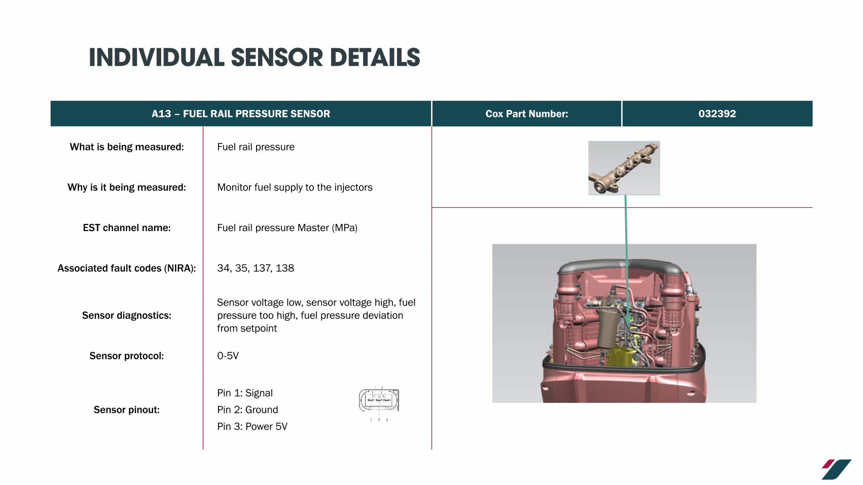
A13 – FUEL RAIL PRESSURE SENSOR Cox Part Number: 032392
What is being measured: Fuel rail pressure
Why is it being measured: Monitor fuel supply to the injectors
EST channel name: Fuel rail pressure Master (MPa)
Associated fault codes (NIRA): 34, 35, 137, 138
Sensor diagnostics:Sensor voltage low, sensor voltage high, fuel pressure too high, fuel pressure deviation from setpoint
Sensor protocol: 0-5V
Sensor pinout:
Pin 1: Signal
Pin 2: Ground
Pin 3: Power 5V

INDIVIDUAL SENSOR DETAILS
A14 – FUEL RAIL HIGH PRESSURE VALVE Cox Part Number: 032395
What is being measured: High pressure valve position
Why is it being measured: Control fuel rail pressure
EST channel name: N/A
Associated fault codes (NIRA): 68
Sensor diagnostics: HPV current high
Sensor protocol: 0-12V
Sensor pinout: Pin 1: 12V
Pin 2: Ground

INDIVIDUAL SENSOR DETAILS
A15 – FUEL INJECTORS Cox Part Number: 032728
What is being measured: Fuel injection duration
Why is it being measured: Engine control
EST channel name: N/A
Associated fault codes (NIRA): 151, 152, 153, 154, 155, 156, 157, 158
Sensor diagnostics: Injector wiring fault, injector fault
Sensor protocol: N/A
Sensor pinout: Pin 1: Power
Pin 2: Ground

INDIVIDUAL SENSOR DETAILS
A16 – GLOW PLUGS Cox Part Number: 022890
What is being measured: Presence of water in fuel
Why is it being measured:Engine protection
EST channel name: Glow Plug Power Master ()
Associated fault codes (NIRA): N/A
Sensor diagnostics: N/A
Sensor protocol: N/A
Sensor pinout: N/A

INDIVIDUAL SENSOR DETAILS
A17 – WATER IN FUEL SENSOR Cox Part Number: 034278
What is being measured: Presence of water in fuel
Why is it being measured: Engine protection
EST channel name: N/A
Associated fault codes (NIRA): 86, 87, 176
Sensor diagnostics: Sensor voltage high, sensor voltage low, water in fuel detected
Sensor protocol: N/A
Sensor pinout:
Pin 1: Signal
Pin 2: Ground
Pin 3: Power

INDIVIDUAL SENSOR DETAILS
A18 – FUEL TEMPERATURE SENSOR Cox Part Number: 026192
What is being measured: Fuel temperature
Why is it being measured: Engine control
EST channel name: Fuel Temperature Master (°C)
Associated fault codes (NIRA): 82, 83
Sensor diagnostics: Sensor voltage high, sensor voltage low
Sensor protocol: 0-5V
Sensor pinout: Pin 1: 5V
Pin 2: Ground

ANALYSIS OF EST DATA

COX EST ANALYSER SHEET
Refer to the video, on how to import data into the EST analyser sheet:
EST Data Import Analyser
NOTECurrent version of the analyser sheet does not capture outboard fault codes.

EST ANALYSER GRAPH INTERPRETATION
1 Below are the characteristics of the graphs defined in the EST analyser:
PRIME PARAMETER RANGE
LOG (ROW) NUMBER IN DATA
PARAMETER TRACES
PRIME PARAMETER BEING ANALYSED
SECONDARY PARAMETER RANGE
LOW AND HIGH WARNING LIMITS
MIN AND MAX DIAGNOSTIC LIMITS
SECONDARY PARAMETER TO SUPPORT ANALYSIS

INDIVIDUAL PARAMETER DETAILS
EST CHANNEL NAME: TIME UNIT OF MEASUREMENT: -
Diagnostic Minimum Warning Low At Idle Speed At Rated Speed Warning High Diagnostic Maximum
Value:
Parameter Type: Defined by ECU based on Zulu time (GMT) and its internal clock as per ISO 8601
To identify time stamp of log, select cell and review formula bar
Cell format: DD/MM/YYY hh:mm:ss.000
(Day/Month/Year Hour:Minute:Second:Millisecond)
Note, the cell will automatically show as mm:ss.0
Trace Key Points:
No trace applicable.
Data cell value contains date of log and time stamp.
Data is logged at 80Hz.
Related Parameters: All other parameters are logged per time stamp
Identifying Data Issues: Diagnostic Actions:
� Check that the log start time is appropriate
� Check that the log end time is appropriate
� Check that the date shown in the time cell is correct
� If date is incorrect – discuss with Cox Aftersales team

INDIVIDUAL PARAMETER DETAILS
EST CHANNEL NAME: ENGINE RUN TIME MASTER UNIT OF MEASUREMENT: HH:MM
Diagnostic Minimum Warning Low At Idle Speed At Rated Speed Warning High Diagnostic Maximum
Value:
Parameter Type: Defined by ECU as a measure of how long the powerhead has been running for.
Trace Key Points:
Cannot be adjusted.
ECU automatically records powerhead hours in 5 minute intervals when running.
Will not match the time stamp of the logged data.
Related Parameters: Engine running
Identifying Data Issues: Diagnostic Actions:
� Check that ECU run hours match that displayed on GCU N/A
(hh:mm)START ECU RUN TIME: 8.25
(hh:mm)END ECU RUN TIME 8.35

INDIVIDUAL PARAMETER DETAILS
EST CHANNEL NAME: ENGINE SPEED MASTER UNIT OF MEASUREMENT: RPM
Diagnostic Minimum Warning Low At Idle Speed At Rated Speed Warning High Diagnostic Maximum
Value: 4,000.0 4,100.0 4,250.00
Parameter Type: Measured engine speed from crankshaft position sensor.
Trace Key Points:
Steady vessel speed in a calm sea, the engine speed should be straight flat line (+/- 100rpm).
Engine speed limit will identify when the ECU will limit engine speed based on gear position and trim angle.
Related Parameters:
Helm throttle demand
Gear selection (see gear selection parameter page)
Trim angle (see trim angle parameter page)
Identifying Data Issues: Diagnostic Actions:
� Identify any large speed fluctuations at steady engine speeds in the trace data.
� Identify any sudden drops to low rpm before recovering in the trace data.
� Exceeds engine speed limits / derates when trimming or in reverse.
� Engine speed does not achieve demanded value.
� Check functionality of crankshaft position sensor.
� Check the wiring to the crankshaft position sensor.
� Check the condition of the trigger wheel teeth for damaged or missing teeth on the crankshaft.
� Check for additional drag on vessel / propeller damage.
� Check for leaks or blockages in intake air path.
� Check for excessive oil carry over in breather system.

INDIVIDUAL PARAMETER DETAILS
EST CHANNEL NAME: ENGINE SPEED MASTER UNIT OF MEASUREMENT: RPM
Identifying Data Issues: Diagnostic Actions:
� Check condition of the propeller.
� Check the loading condition of the vessel.
� Check the hull condition (clean or dirty).
� Check for excessive propeller cavitation.

INDIVIDUAL PARAMETER DETAILS
EST CHANNEL NAME: ENGINE LOAD UNIT OF MEASUREMENT: %
Diagnostic Minimum Warning Low At Idle Speed At Rated Speed Warning High Diagnostic Maximum
Value:
Parameter Type:Calculated parameter based on the actual fuel volume flow rate against the known maximum fuel volume flow rate for that engine speed.
Trace Key Points:
Engine load will increase with engine speed.
It will vary depending upon:
� Vessel loading / hull condition (e.g. clean or dirty)
� Propeller being used
Aim is to achieve 100% engine load at maximum possible engine speed at full throttle at the vessel maximum gross displacement (full fuel / typical loading).
Related Parameters:Engine Speed
Volume Fuel Flow Rate
Identifying Data Issues: Diagnostic Actions:
� At maximum engine speed, engine load should be 100%.
� Engine load is lower than when vessel was commissioned.� Adjust size or pitch of propeller to increase / decrease engine load at full throttle.

INDIVIDUAL PARAMETER DETAILS
EST CHANNEL NAME: ENGINE LOAD UNIT OF MEASUREMENT: %
Identifying Data Issues: Diagnostic Actions:
� Check condition of the propeller for damage or wear.
� Check the loading condition of the vessel.
� Check the hull condition (clean or dirty).
� Check for excessive propeller cavitation.
� Check the position of the anti-ventilation plate in relation to the bottom of the hull
� Effect if too low:
� Increased water drag on outboard
� Adverse effect on vessel handling
� Effect if too high:
� Decrease in propeller efficiency due to increase in propeller ventilation (breaks water surface)
� A particular concern on multi-outboard installations as in a turn, the outer outboard rises out of the water during the turn

INDIVIDUAL PARAMETER DETAILS
EST CHANNEL NAME: INTAKE MANIFOLD TEMPERATURE MASTER UNIT OF MEASUREMENT: °C
Diagnostic Minimum Warning Low At Idle Speed At Rated Speed Warning High Diagnostic Maximum
Value: 90.0
Parameter Type: Measured by the TMAP sensor
Trace Key Points:
Trace should remain steady rising / falling gently during engine usage.
During engine usage, air temperature will increase by a few degrees to a maximum due to radiated heat from the engine.
Related Parameters: Ambient air temperature.
Identifying Data Issues: Diagnostic Actions:
� Measured air temperature is significantly higher than the known ambient air temperature.
� Spikes in the trace curve.
� Rapid increases and decreases in the trace.
� Intake air temperature exceeds diagnostic limit.
� Check the functionality of the sensor by comparing to known ambient air temperature when engine is cold.
� Check condition of wiring to connector.
� Check for damage to sensor element.
� Check for evidence of heat damage to engine components.
� Thermal event under cowling.

INDIVIDUAL PARAMETER DETAILS
EST CHANNEL NAME: BANK 1 / 2 INTAKE AIR MASS FLOW MASTER UNIT OF MEASUREMENT: KG/H
Diagnostic Minimum Warning Low At Idle Speed At Rated Speed Warning High Diagnostic Maximum
Value: 650.0
Parameter Type: Measured on both air intakes via the mass air flow sensors.
Trace Key Points:
Trace should remain stable at different engine speeds.Trace may spike when engine is accelerating or decelerating at high engine loads.A concern is when there is a high mass air flow event which exceeds limits for a continuous period.Single spikes may occur though the ECU software will account for this and prevent fault codes from being raised.
Related Parameters:
Engine SpeedBank – Bank Intake Air Mass Flow ImbalanceAir intake temperatureAir intake pressure
Identifying Data Issues: Diagnostic Actions:
� Identify if the bank-bank balance is abnormally high from previous logged data for outboard for same engine speed.
� A high imbalance (>60kg/h) exists for high and low engine speeds.
� Potential error due to signal issue rather than problem with air flow.
� Check air path for leaks.� Check the condition and functionality of the turbochargers.� Check for exhaust gas leaks.� Check the condition of the turbo boost control valve electrical connectors.

INDIVIDUAL PARAMETER DETAILS
EST CHANNEL NAME: BANK 1 / 2 INTAKE AIR MASS FLOW MASTER UNIT OF MEASUREMENT: KG/H
Identifying Data Issues: Diagnostic Actions:
� Check against manifold air pressure and temperature to identify any concerns.
� Check for blockages in the air path.
� Check the conditional service life of the air filters.

INDIVIDUAL PARAMETER DETAILS
EST CHANNEL NAME: MAF BANK IMBALANCE UNIT OF MEASUREMENT: KG/H
Diagnostic Minimum Warning Low At Idle Speed At Rated Speed Warning High Diagnostic Maximum
Value: 0.0 140.0 150.0
Parameter Type: Is the calculated difference between Bank 1 and Bank 2 mass air flows.
Trace Key Points:
Trace should remain stable at different engine speeds.Trace may spike when engine is accelerating / decelerating at high engine loads.Only concern are any continuous high mass air flow events.Single spikes may occur however ECU software will account for this.
Related Parameters:
Bank 1 / 2 MAF flow ratesEngine speedAir intake temperatureAir intake pressure
Identifying Data Issues: Diagnostic Actions:
� Identify if the bank-bank balance is abnormally high from previous logged data for outboard for same engine speed.
� A high imbalance (>60kg/h) exists for high and low engine speeds.
� Check air path for leaks.
� Check the condition and functionality of the turbochargers.
� Check for exhaust gas leaks.
� Check the condition of the turbo boost control valve electrical connectors.

INDIVIDUAL PARAMETER DETAILS
EST CHANNEL NAME: INTAKE MANIFOLD PRESSURE MASTER UNIT OF MEASUREMENT: kPa
Diagnostic Minimum Warning Low At Idle Speed At Rated Speed Warning High Diagnostic Maximum
Value: 255.0 310.0
Parameter Type: Measured parameter by TMAP sensor.
Trace Key Points:Intake air pressure will increase with engine speed.
Pressure trace will be stable at steady engine speed.
Related Parameters:
Intake air temperature
Engine speed
Boost set point
Identifying Data Issues: Diagnostic Actions:
� When engine is off, air pressure should read ambient air pressure (approx. 100kPa).
� Identify if air pressure is less than 100kPa (negative air pressure in manifold).
� Trace does not increase as engine speed increases.
� Exceeds diagnostic max limit.
� Check air path for leaks.
� Check the condition and functionality of the turbochargers.
� Check for exhaust gas leaks.
� Check the condition of the turbo boost control valve electrical connectors.
� Check the functionality of the turbo boost control valve.
INDIVIDUAL PARAMETER DETAILS
EST CHANNEL NAME: BOOST SETPOINT MASTER UNIT OF MEASUREMENT: kPa
Diagnostic Minimum Warning Low At Idle Speed At Rated Speed Warning High Diagnostic Maximum
Value:
Parameter Type: ECU calculated parameter depending on engine speed.
Trace Key Points:Boost setpoint changes with engine speed.
Predetermined values defined in the engine calibration.
Related Parameters:
Engine load demand
Engine speed
Boost setpoint to actual deviation
Identifying Data Issues: Diagnostic Actions:
� Boost setpoint does not change with engine speed.
� Setpoint trace fluctuates whilst engine speed is stable.N/A

INDIVIDUAL PARAMETER DETAILS
EST CHANNEL NAME: BOOST SET POINT TO ACTUAL DEVIATION UNIT OF MEASUREMENT: kPa
Diagnostic Minimum Warning Low At Idle Speed At Rated Speed Warning High Diagnostic Maximum
Value: -30.0 0.0 30.0
Parameter Type: Calculated based on the required boost set point pressure and actual measured intake pressure
Trace Key Points:
Stable when engine speed is stable.
Will occasionally spike as engine is accelerating / decelerating.
Limits will vary depending on engine speed.
Depending on trace:
� Positive number = underachieving boost pressure.
� Negative number = overachieving boost pressure.
Over boosting on a transient event (acceleration / deceleration) is expected.
If above limit lines for an extended period, a concern should be raised.
Compare against engine speed.
Related Parameters:
Boost set point
Intake air pressure
Engine speed
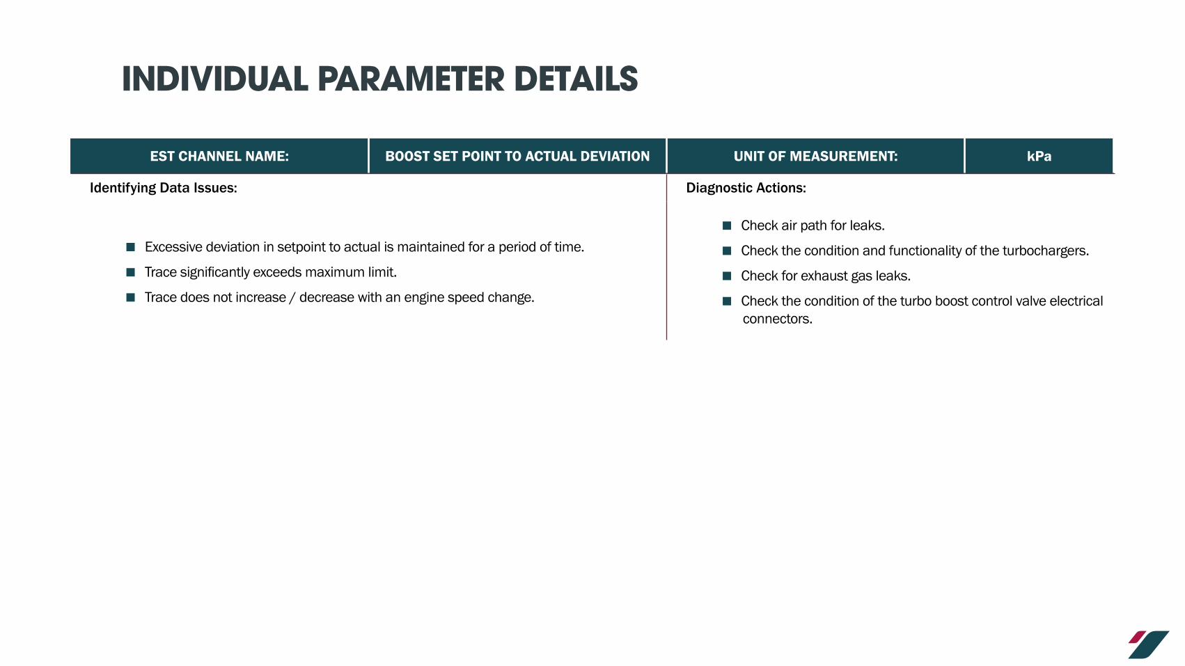
INDIVIDUAL PARAMETER DETAILS
EST CHANNEL NAME: BOOST SET POINT TO ACTUAL DEVIATION UNIT OF MEASUREMENT: kPa
Identifying Data Issues: Diagnostic Actions:
� Excessive deviation in setpoint to actual is maintained for a period of time.
� Trace significantly exceeds maximum limit.
� Trace does not increase / decrease with an engine speed change.
� Check air path for leaks.
� Check the condition and functionality of the turbochargers.
� Check for exhaust gas leaks.
� Check the condition of the turbo boost control valve electrical connectors.
INDIVIDUAL PARAMETER DETAILS
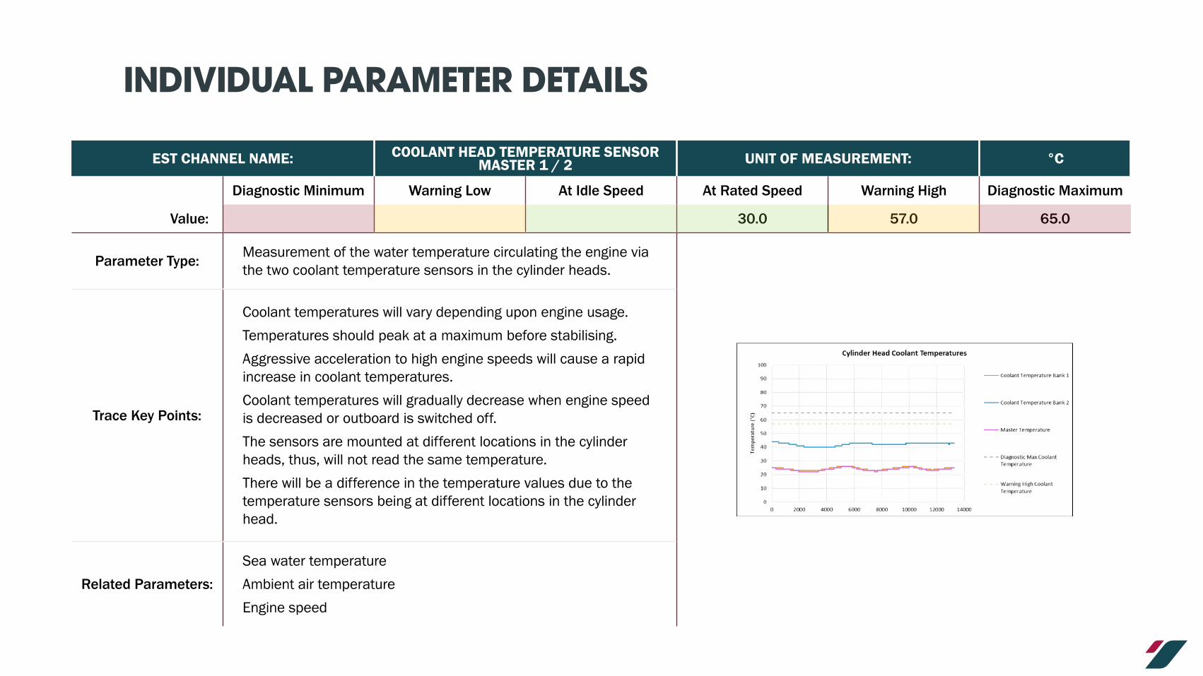
EST CHANNEL NAME: COOLANT HEAD TEMPERATURE SENSOR MASTER 1 / 2 UNIT OF MEASUREMENT: °C
Diagnostic Minimum Warning Low At Idle Speed At Rated Speed Warning High Diagnostic Maximum
Value: 30.0 57.0 65.0
Parameter Type: Measurement of the water temperature circulating the engine via the two coolant temperature sensors in the cylinder heads.
Trace Key Points:
Coolant temperatures will vary depending upon engine usage.
Temperatures should peak at a maximum before stabilising.
Aggressive acceleration to high engine speeds will cause a rapid increase in coolant temperatures.
Coolant temperatures will gradually decrease when engine speed is decreased or outboard is switched off.
The sensors are mounted at different locations in the cylinder heads, thus, will not read the same temperature.
There will be a difference in the temperature values due to the temperature sensors being at different locations in the cylinder head.
Related Parameters:
Sea water temperature
Ambient air temperature
Engine speed

INDIVIDUAL PARAMETER DETAILS
EST CHANNEL NAME: COOLANT HEAD TEMPERATURE SENSOR MASTER 1 / 2 UNIT OF MEASUREMENT: °C
Identifying Data Issues: Diagnostic Actions:
� Continual rise in coolant temperature when engine speed decreases / is low / extended periods of idling.
� Coolant temperature does not rise during usage or for long periods of idling.
� Deviation between sensors should not exceed 100°C.
� Coolant temperature exceeds diagnostic max limit.
� Large difference in coolant temperature readings.
� Check outboard water pick up points for blockages.
� Check water pick up points are submerged when running.
� Check functionality of the thermostats.
� Check for blockages around the thermostats.
� Check functionality and condition of the water pump.
� Check for degradation in coolant flow around outboard.
� Check the functionality and condition of the coolant temperature sensors.
� Check the condition of the temperature sensors and related wiring.

INDIVIDUAL PARAMETER DETAILS
EST CHANNEL NAME: COOLANT TEMPERATURE MASTER UNIT OF MEASUREMENT: °C
Diagnostic Minimum Warning Low At Idle Speed At Rated Speed Warning High Diagnostic Maximum
Value:
Parameter Type: Is the maximum of the coolant temperature sensors
Trace Key Points: Trace will follow either or both of the coolant temperature traces depending on which is the highest.
Related Parameters: Coolant temperatures
Identifying Data Issues: Diagnostic Actions:
� Significant difference to either of the coolant temperature sensors. N/A

INDIVIDUAL PARAMETER DETAILS
EST CHANNEL NAME: CYLINDER HEAD TEMPERATURE SENSOR MASTER 1 / 2 UNIT OF MEASUREMENT: °C
Diagnostic Minimum Warning Low At Idle Speed At Rated Speed Warning High Diagnostic Maximum
Value: 60.0 80.0
Parameter Type: Measured cylinder head metal temperatures by the cylinder head temperature sensors
Trace Key Points:Cylinder head temperatures will vary depending on engine usage.
Due to the variations in coolant flow through the engine, there will be a difference between the readings of the temperature sensors.
Related Parameters:
Coolant temperatures.
Engine speed.
Ambient air temperature.
Identifying Data Issues: Diagnostic Actions:
� Before 1st start, the cylinder head temperature sensors should measure ambient air temperature.
� Traces do not follow the same profile, e.g. increase / decrease at varying rates.
� With engine off, remove sensors from engine and check to determine if ambient air temperature is measured.
� Check the condition of the sensor connector and wiring.

INDIVIDUAL PARAMETER DETAILS
EST CHANNEL NAME: OIL TEMPERATURE MASTER UNIT OF MEASUREMENT: °C
Diagnostic Minimum Warning Low At Idle Speed At Rated Speed Warning High Diagnostic Maximum
Value: 80.0 110.0
Parameter Type: Measured temperature by the oil temperature sensor
Trace Key Points:
Trace will gradually increase / decrease depending on engine usage.At prolonged maximum engine load, the oil temperature should reach a maximum and stabilise.
Related Parameters:
Ambient air temperatureCoolant temperatureEngine loadEngine speed
Identifying Data Issues: Diagnostic Actions:
� Any sudden spikes in temperature.
� Temperature continues to rise after engine speed decreases.
� Before 1st start, measured temperature should be similar to ambient air temperature.
� Oil temperature is less than coolant temperatures.
� Check for high coolant temperatures.
� Check the condition of the sensor connector and wiring.
� Check the condition of the oil for excessive aeration / thermal degradation / debris / soot content / excessive water content.
� Check how long the oil has been used for – change if exceeds engine requirements.
� Check the functionality of the oil pump.
� Check the functionality of the water pump.

INDIVIDUAL PARAMETER DETAILS
EST CHANNEL NAME: OIL PRESSURE MASTER UNIT OF MEASUREMENT: kPa
Diagnostic Minimum Warning Low At Idle Speed At Rated Speed Warning High Diagnostic Maximum
Value: 40.0 140.0 400.0 750.0
Parameter Type: Measured by the oil pressure sensor
Trace Key Points:
Pressure will follow engine speed.
Magnitude of the oil pressure will vary depending on oil temperature (cold oil temperature = higher oil pressure, high oil temperature = lower oil pressure)
Related Parameters:
Engine speed
Oil temperature
Oil filter outlet pressure
Identifying Data Issues: Diagnostic Actions:
� Spikes and excessive fluctuations of oil pressure trace.
� Does not increase / decrease with engine speed.
� Excessive fluctuations.
� At steady engine speed, the pressure trace degrades.
� Check for external oil leaks from powerhead.
� Check the oil level.
� Check the condition and confirm service life of the oil filter.
� Check the condition of the oil for excessive aeration / thermal degradation / debris / soot content / excessive water content.

INDIVIDUAL PARAMETER DETAILS
EST CHANNEL NAME: OIL PRESSURE MASTER UNIT OF MEASUREMENT: kPa
Identifying Data Issues: Diagnostic Actions:
� Does not rise above the “warning low” limit once engine speed exceeds idle speed.
� Exceeds maximum oil pressure limits at start up (of concern when oil is cold).
� Compare against oil temperature (high oil temperature and low oil pressure may indicate internal fault).
� Check for blockages in the CCV system.
� Check the functionality and performance of the oil pressure sensor.
� Measure the oil level in the oil tank.

INDIVIDUAL PARAMETER DETAILS
EST CHANNEL NAME: ENGINE OIL FILTER OUTLET PRESSURE MASTER UNIT OF MEASUREMENT: kPa
Diagnostic Minimum Warning Low At Idle Speed At Rated Speed Warning High Diagnostic Maximum
Value: 60.0 180.0 430.0
Parameter Type: Measured at the oil filter outlet to engine
Trace Key Points:Pressure will follow engine speed.
Oil filter outlet pressure will be greater than the oil pressure sensor.
Related Parameters:
Oil pressure
Engine speed
Oil temperature
Identifying Data Issues: Diagnostic Actions:
� Spikes and excessive fluctuations of oil pressure trace.
� Does not increase / decrease with engine speed.
� Excessive fluctuations.
� At steady engine speed, the pressure trace degrades.
� Check for external oil leaks from powerhead.
� Check the oil level.
� Check the condition and confirm service life of the oil filter.
� Check the condition of the oil for excessive aeration / thermal degradation / debris / soot content / excessive water content.

INDIVIDUAL PARAMETER DETAILS
EST CHANNEL NAME: ENGINE OIL FILTER OUTLET PRESSURE MASTER UNIT OF MEASUREMENT: kPa
Identifying Data Issues: Diagnostic Actions:
� Does not rise above the “warning low” limit once engine speed exceeds idle speed.� Compare against oil temperature (high oil temperature and low oil pressure may indicate internal fault).
� Check for blockages in the CCV system

INDIVIDUAL PARAMETER DETAILS
EST CHANNEL NAME: FUEL TEMPERATURE MASTER UNIT OF MEASUREMENT:
Diagnostic Minimum Warning Low At Idle Speed At Rated Speed Warning High Diagnostic Maximum
Value: 45.0 95.0
Parameter Type: Measured fuel temperature at lift pump
Trace Key Points: Trace will be stable throughout engine running.
Related Parameters:Ambient air temperature
Fuel filter out pressure
Identifying Data Issues: Diagnostic Actions:
� Any spikes or fluctuations in the trace.
� Before 1st start, measured temperature should be similar to ambient air temperature.
� Exceeds diagnostic max limit.
� Check the condition of the connector and wiring.
� With engine off, remove sensors from engine and check to determine if ambient air temperature is measured.
� Check fuel level in tank.
� Check PDM for excessive heat.
� Check the functionality and condition of the fuel cooler.

INDIVIDUAL PARAMETER DETAILS
EST CHANNEL NAME: FUEL RAIL PRESSURE MASTER UNIT OF MEASUREMENT: MPa
Diagnostic Minimum Warning Low At Idle Speed At Rated Speed Warning High Diagnostic Maximum
Value: 180.0 210.0
Parameter Type: Measured fuel rail pressure one Bank 1 fuel rail
Trace Key Points:
Fuel rail pressure will increase with engine speed.
May initially spike before settling when accelerating / decelerating.
Fuel rail pressure is measure in MPa where as fuel filter out pressure is measured in kPa (1MPa = 1,000kPa).
Related Parameters:
Fuel temperatureEngine speedEngine loadFuel flow rate
Identifying Data Issues: Diagnostic Actions:
� Fuel rail pressure does not increase with engine speed.
� At steady engine speed, fuel rail pressure degrades.
� Any spikes or excessive fluctuations in the trace.
� Check fuel tank level.
� Check for fuel leaks (CAUTION – do not work on high pressure fuel system when fuel pressure is high).
� Check the condition and service life of fuel filter.
� Check the condition of the connector and wiring.

INDIVIDUAL PARAMETER DETAILS
EST CHANNEL NAME: UNIT OF MEASUREMENT:
Diagnostic Minimum Warning Low At Idle Speed At Rated Speed Warning High Diagnostic Maximum
Value: 0.5 5.0
Parameter Type: Measured pressure at the lift pump
Trace Key Points:Fuel filter pressure will decrease as engine speed increases.
Will exhibit random pressure spikes as shown.
Related Parameters:Engine speed
Fuel temperature
Identifying Data Issues: Diagnostic Actions:
� Fuel pressure degrades to zero whilst engine is running
� Check fuel tank level.
� Check the functionality and performance of the fuel lift pump.
� Check the fuel system for blockages including fuel filter.
� Check the vessel fuel system for leaks.

INDIVIDUAL PARAMETER DETAILS
EST CHANNEL NAME: FUEL VOLUME RATE MASTER UNIT OF MEASUREMENT: L/H
Diagnostic Minimum Warning Low At Idle Speed At Rated Speed Warning High Diagnostic Maximum
Value:
Parameter Type: Calculated by ECU based on engine speed and injection quantity.
Trace Key Points:
Fuel flow rate will follow engine speed, e.g. it will increase as engine speed increases.
Fuel flow rate is stable at steady engine speeds.
When accelerating, the fuel flow rate will spike high before stabilising when engine speed is constant.
Fuel flow rate will drop when vessel gets on plane as the water resistance is less thus reduced load applied to engine.
Related Parameters:Fuel temperature
Engine speed
Identifying Data Issues: Diagnostic Actions:
� If fuel flow rate does not follow engine speed, e.g. fuel flow rate drops whilst engine speed is stable.
� Excessive fluctuations that do not decay with steady engine speed.
� Check performance of fuel pressure sensors.
� Check the volume of fuel in the vessel tank(s).
� Check for blockages in the fuel system including fuel filter.

INDIVIDUAL PARAMETER DETAILS
EST CHANNEL NAME: ECU VOLTAGE MASTER UNIT OF MEASUREMENT: VOLTS
Diagnostic Minimum Warning Low At Idle Speed At Rated Speed Warning High Diagnostic Maximum
Value: 6.0 11.5 12.5 12.5 15.0 16.0
Parameter Type: Measured voltage received by ECU
Trace Key Points:
Should remain stable at set point for all engine speeds.
Will drop to low voltage during engine cranking.
Note, with the implementation of the voltage regulator, this channel only measures voltage input to the ECU and not the battery or charging voltage.
Related Parameters: Engine speed
Identifying Data Issues: Diagnostic Actions:
� Voltage trace is unstable / fluctuates.
� Voltage drops or decays at steady engine speeds.
� Voltage increases above 14V will affect system functionality.
� Voltage is below diagnostic minimum before engine is started.
� Check charging circuit is functioning correctly.
� Check condition and voltage of outboard batteries.
� Check the condition and continuity of the wiring looms.
� Check the functionality and condition of the PDM.
� Fault with the voltage sensor in ECU.
INDIVIDUAL PARAMETER DETAILS
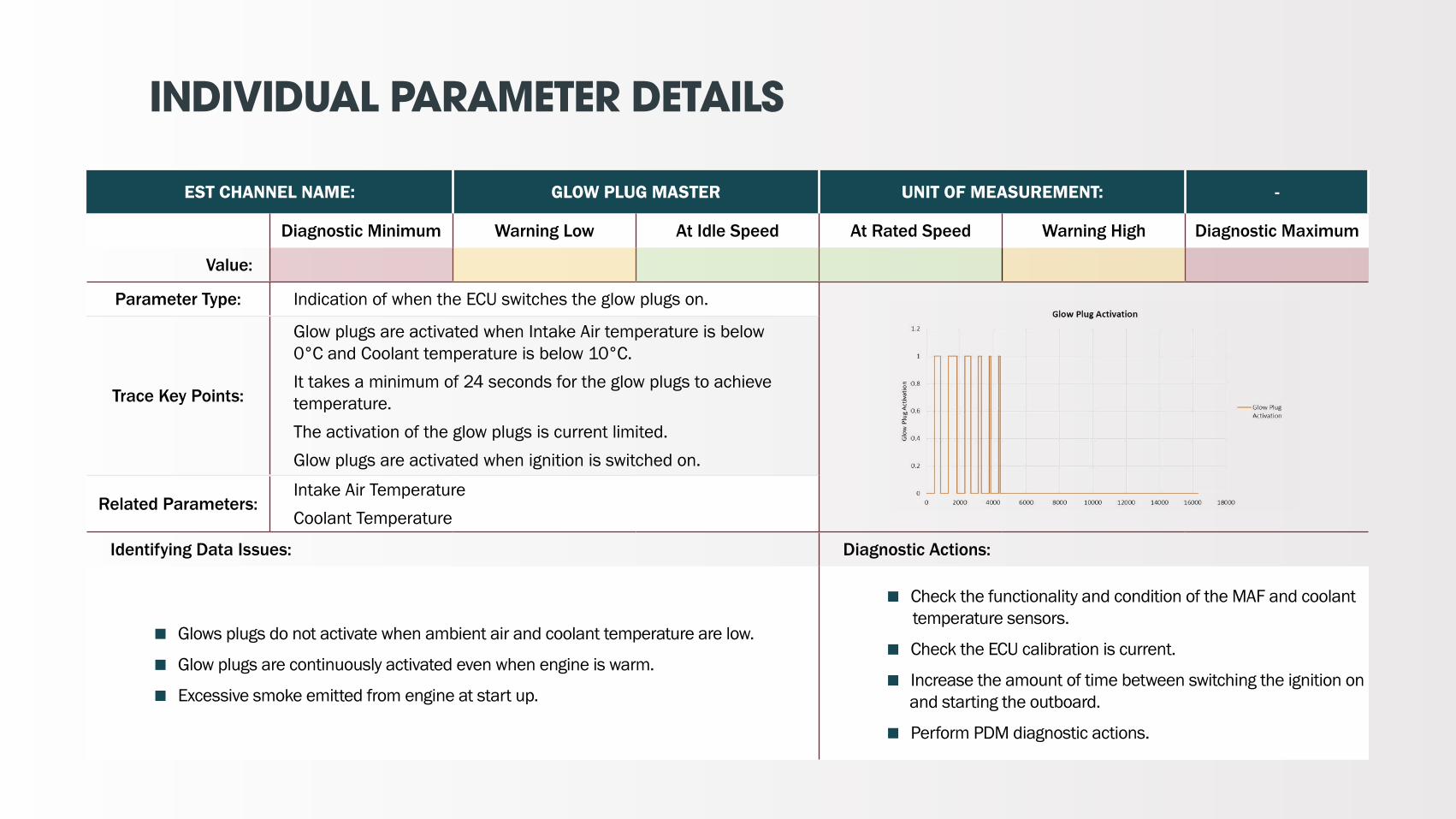
EST CHANNEL NAME: GLOW PLUG MASTER UNIT OF MEASUREMENT: -
Diagnostic Minimum Warning Low At Idle Speed At Rated Speed Warning High Diagnostic Maximum
Value:
Parameter Type: Indication of when the ECU switches the glow plugs on.
Trace Key Points:
Glow plugs are activated when Intake Air temperature is below 0°C and Coolant temperature is below 10°C.
It takes a minimum of 24 seconds for the glow plugs to achieve temperature.
The activation of the glow plugs is current limited.
Glow plugs are activated when ignition is switched on.
Related Parameters:Intake Air Temperature
Coolant Temperature
Identifying Data Issues: Diagnostic Actions:
� Glows plugs do not activate when ambient air and coolant temperature are low.
� Glow plugs are continuously activated even when engine is warm.
� Excessive smoke emitted from engine at start up.
� Check the functionality and condition of the MAF and coolant temperature sensors.
� Check the ECU calibration is current.
� Increase the amount of time between switching the ignition on and starting the outboard.
� Perform PDM diagnostic actions.

INDIVIDUAL PARAMETER DETAILS
EST CHANNEL NAME: TRIM POSITION MASTER UNIT OF MEASUREMENT: %
Diagnostic Minimum Warning Low At Idle Speed At Rated Speed Warning High Diagnostic Maximum
Value:
Parameter Type: Calculated by ECU based on the min and max trim angles calibrated in ECU via EST.
Trace Key Points:
Note, EST trim angle is measured as a % of the calibrated trim settings.
The EST analyser converts this into a sensor angle position (°).
By converting to an angle position, it can be identified when the trim position exceeds the engine speed derate and limit.
Related Parameters: Engine speed
Identifying Data Issues: Diagnostic Actions:
� Note if any non-demanded trim events occur.� Trim angle changes as engine speed is increased.� Engine derates do not come into effect when high trim angle is applied.
� Check functionality of PTT unit.� Check for any PTT hydraulic fluid leaks.� Check the functionality of the trim switches on the helm control and outboard side switch whilst engine is off.� Check PTT angle sensor functionality and position.� Recalibrate the PTT trim position in EST.
GEAR DERATE LIMITForward 1500rpm 0rpmNeutral 2000rpm 0rpmReverse 1400rpm 0rpm

INDIVIDUAL PARAMETER DETAILS
EST CHANNEL NAME: GEAR POSITION MASTER UNIT OF MEASUREMENT: -
Diagnostic Minimum Warning Low At Idle Speed At Rated Speed Warning High Diagnostic Maximum
Value:
Parameter Type: Indication by ECU as to the gear position
Trace Key Points:
Depending on what gear is selected, the trace is either:� Forward = 1� Neutral = 0� Reverse = -1Gear selection is dependent on engine speed and sufficient reverse torque load applied to break the contact between the dog gears.When in forward, the engine speed is limited to 4000rpm.When in neutral, engine speed is limited to 4000rpm.When in reverse, engine speed is limited to 1400rpm.
Related Parameters: Engine speed
Identifying Data Issues: Diagnostic Actions:
� Gear value shown is not the desired gear.
� Gear position does not change when requested.
� Check the CAN linkage between helm control unit and outboard.
� Check the functionality and condition of the gear shift actuator.
� Perform PDM diagnostic actions.

INDIVIDUAL PARAMETER DETAILS
EST CHANNEL NAME: ENGINE STATE MASTER UNIT OF MEASUREMENT: -
Diagnostic Minimum Warning Low At Idle Speed At Rated Speed Warning High Diagnostic Maximum
Value:
Parameter Type: ECU defined parameter based on engine state at given moment.
Trace Key Points:
There are 4 different engine states:
� 0 = Not started
� 1 = Cranking
� 2 = Idle
� 3 = Above / Off idle
Parameter used to define when engine is starting.
Related Parameters: Engine speed
Identifying Data Issues: Diagnostic Actions:
� Engine state trace does not register a change in engine state. � Perform PDM diagnostic actions.

INDIVIDUAL PARAMETER DETAILS
EST CHANNEL NAME: ENGINE THROTTLE VALVE 2 POSITION MASTER UNIT OF MEASUREMENT: %
Diagnostic Minimum Warning Low At Idle Speed At Rated Speed Warning High Diagnostic Maximum
Value:
Parameter Type: Measured parameter of the throttle shut off valve.
Trace Key Points:
This is a shut off valve.
When engine is running, the throttle position will default to 102%.
It will only vary during engine cranking.
Related Parameters: Engine speed
Identifying Data Issues: Diagnostic Actions:
� Throttle position is not constant whilst engine is running.
� If not open or closed when not at engine start, concern should be raised.� Check functionality of the shut off valve.

INDIVIDUAL PARAMETER DETAILS
EST CHANNEL NAME: AMBIENT AIR TEMPERATURE UNIT OF MEASUREMENT: °C
Diagnostic Minimum Warning Low At Idle Speed At Rated Speed Warning High Diagnostic Maximum
Value:
Parameter Type: Calculated by ECU based on average of the 2 air flow sensor readings.
Parameter not logged in EST Data.Trace Key Points:
Ambient air temperature is not logged in the EST data.
To enable an accurate ambient air temperature reading, the air flow sensors require an air flow across them, thus air temperature is only accurate when the engine is running.
Related Parameters: Intake air mass flow rate
Identifying Data Issues: Diagnostic Actions:
� ECU calculated ambient air temperature is significantly different to actual ambient air temperature.
� When air temperature exceeds 90°C.
� Check the functionality and condition of the MAF sensors.
� Check for blockages in the air path.
� Thermal event under cowling.

JSON FILES

WHAT ARE JSON FILES
1 JSON files capture ECU information when “START SERVICE” or “STOP SERVICE” is selected in EST.
2 The information that is captured by a JSON file includes:
� Time and date stamp of when file was created
� Part serial numbers
� ECU calibration being used
� Active fault codes with parameter snap shot of when fault code occurred
� Engine usage history
� The maximum and minimum measured parameter values of all time
� ECU settings – Channels that can be adjusted via EST
3 Every time EST is connected to the ECU, 2 files will be created.

COX JSON FILE REQUIREMENT
1 When submitting any EST data file(s), the 2x JSON files from the Start Service and Stop Service of the logged EST session must also be submitted.
2 Cox require JSON files to understand:
� The usage profile of the outboard
� The outboard conditions at the time fault codes have been triggered by the ECU
� Software and calibration are correct
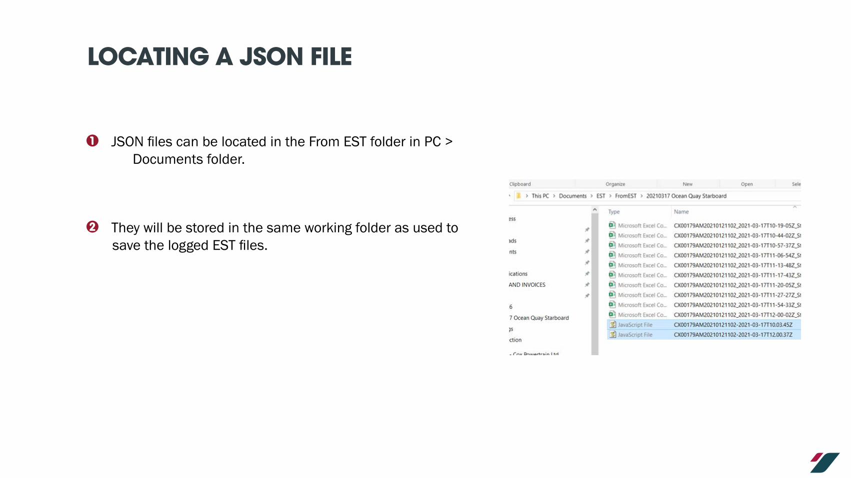
LOCATING A JSON FILE
1 JSON files can be located in the From EST folder in PC > Documents folder.
2 They will be stored in the same working folder as used to save the logged EST files.

OPENING JSON FILE
1 JSON files can be viewed using Notepad
2 To open the file:
� Select the JSON file to open
� Right click
� Scroll to “Open with”
� Select “Notepad”

READING A JSON FILE
1 Below defines the various parts of the JSON file:
FILE WAS CREATED AT “START” OR “STOP” SERVICE
EST USER LICENSE THAT WAS USED WHEN CREATING FILE
KVASER CAN TOOL USED SERIAL NUMBER
OUTBOARD POWER RATING
DATE AND TIME STAMP OF FILE IN ISO 8601 FORMAT
INDIVIDUAL INJECTOR DETAILS INCLUDING TRIM
CODEECU SERIAL NUMBER
INJECTOR SERIAL NUMBERS
POWERHEAD SERIAL NUMBER
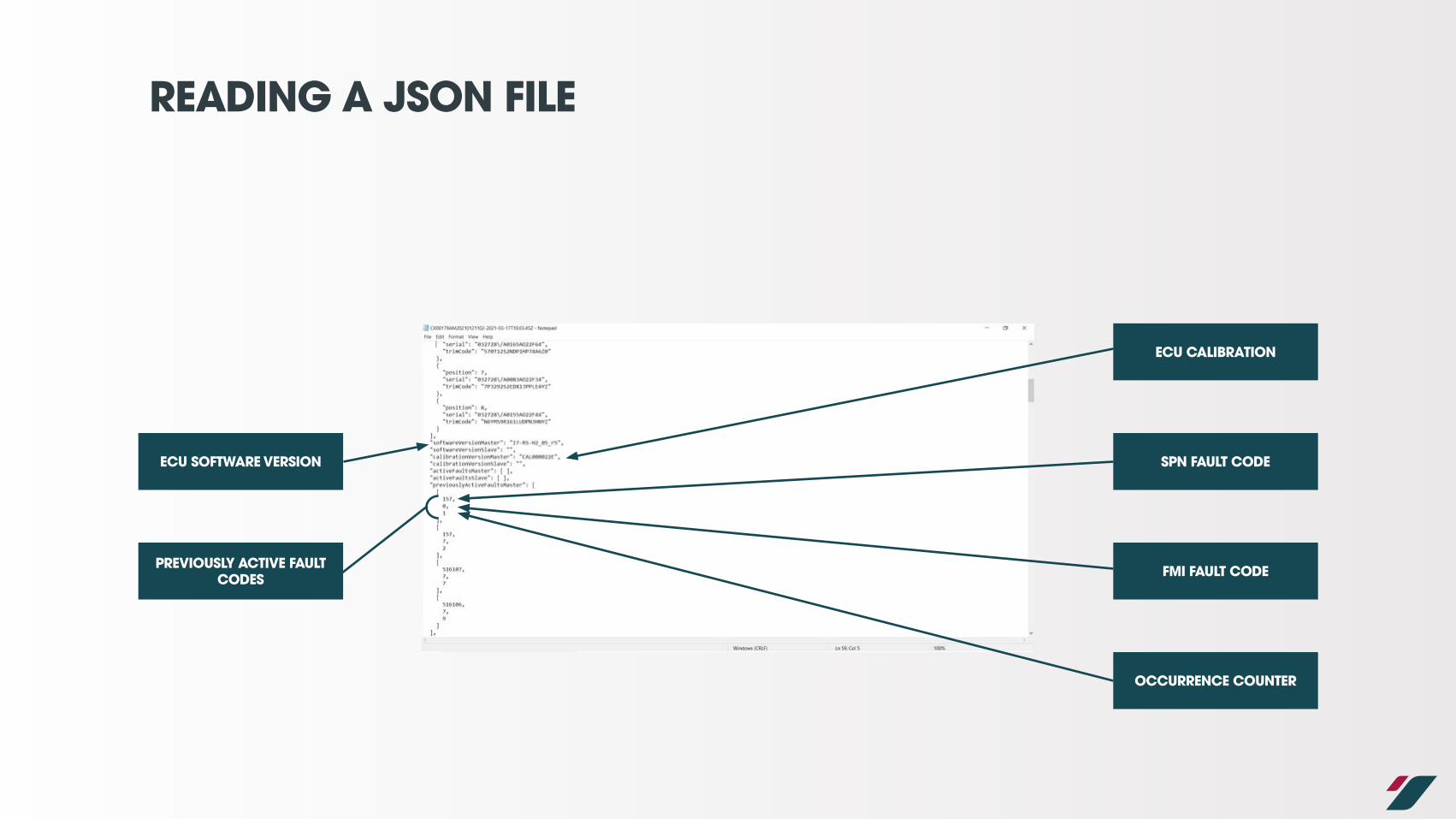
READING A JSON FILE
ECU CALIBRATION
SPN FAULT CODEECU SOFTWARE VERSION
FMI FAULT CODEPREVIOUSLY ACTIVE FAULT CODES
OCCURRENCE COUNTER

READING A JSON FILE
FAULT CODE DETAILS
LOGGED ENGINE PARAMETERS AT TIME FAULT
CODE LOGGED
LIST OF PREVIOUSLY ACTIVE FAULT CODES
INDIVIDUAL ECU PARAMETER SNAP SHOT FOR EACH FAULT
CODE LOGGEDPARAMETERS ARE DEFINED
IN EST “FAULT FREEZE FRAMES” PAGE

READING A JSON FILE
ENGINE LOAD HISTORY VALUESENGINE LOAD HISTORY

READING A JSON FILE
MIN AND MAX RECORDED ENGINE PARAMETERS
POWERHEAD SERIAL NUMBER
OUTBOARD RUN HOURS
ECU SERIAL NUMBER
OUTBOARD SERIAL NUMBER

READING A JSON FILE
PARAMETERS THAT ARE ADJUSTED IN EST
MAXIMUM CALIBRATED TRIM ANGLE
PROPELLER ROTATION DIRECTION
OUTBOARD SERIAL NUMBER
NUMBER OF OUTBOARD(S) ON VESSEL
OUTBOARD LOCATION ON VESSEL
MINIMUM CALIBRATED TRIM ANGLE

WHAT TO CHECK ON JSON FILES
Information that should be checked on a JSON file:
1 Outboard serial number
2 Powerhead serial number
3 Outboard run hours
4 Active fault codes and number of occurrences
5 Min and Max recorded parameters
6 Parameters that are adjusted in EST
� Outboard serial number
� Calibrated trim angles
� Outboard location on vessel
� Number of outboards on vessel
� Rotation of the propeller
Refer to the DFC Matrix available on the Cox Portal for further information on outboard fault codes.

SUMMARY

SUMMARY
1 If you are unsure of anything, please contact the Cox Aftersales team to discuss.
2 This information pack will be updated with more information periodically.
3 Analysing data effectively is a skill that takes time to develop.
4 Looking at the trend over time can be more informative than looking at an instantons point.
5 When raising a concern to Cox via the Cox Portal, ensure to include as much detail as possible.
� Pictures and videos tell a 1000 words!
6 Ensure to define what you are sending to Cox.
� A table defining the various logs taken help us to follow the sequence of events.

THANK YOUANY QUESTIONS?