Storage Resource Managers: Essential Components for the Grid Arie Shoshani Staff:
Upload
seahorse88Category
view
217download
0
7/28/2019 Essential Knowledge for Potential Offshore Installation Managers
http://slidepdf.com/reader/full/essential-knowledge-for-potential-offshore-installation-managers 1/101
Page 1
Essential KnowledgeFor
PotentialOffshore
Installation
Managers
Written by
Tim Allsop & Charlie Bell
Copyright 2010

7/28/2019 Essential Knowledge for Potential Offshore Installation Managers
http://slidepdf.com/reader/full/essential-knowledge-for-potential-offshore-installation-managers 2/101
Page 2
Table of Contents Author notes 3Introduction 5Installation Design Criteria 8Health Safety & Environment Considerations 13Leadership Qualities 18
Training & Standards 21Qualifications & Accident Investigation Processes 30Environmental Considerations 37Emergency Response Procedures & Incident Command Systems 40Distributed Control Systems 43Permit To Work 47Planned Maintenance Systems 52Production, Process & Drilling Operations 53
Oil Spill Response Principles 79Summary 100
PREFACE
This book is the combined efforts of Charles Bell & Tim Allsop originally from different backgrounds, butwho share a common passion and understanding of what it takes to hold the position of Installation Manageron an offshore Production Facility.
Due to the growing global demand for combustible fuels, and the challenging and demanding environments weare now forced to go looking for these fuels in, the world has taken on a new respect for the environment andpart of this process is to hold the operators through their managers both responsible and accountable forensuring a safe and reduced risk (as low as practicable) environment and process for the exploration, refiningand delivery of hydrocarbons to us the general public.
This book is not the “be all end all” definitive description of what it takes to perform the roles andresponsibilities of an Offshore Installation Manager, but it does touch on enough relevant subjects to allow thereaders to have a better understanding of what it does take to be an Offshore Installation Manager.
It is important to take into consideration that information gives you knowledge, this is a one dimensionalapproach to the situation and position, what makes a more proficient OIM is the confidence he has to deal withthe daily grind and challenges he will face working in an offshore environment, there is no substitute forexperience, what we are always looking for when assessing and teaching existing & perspective OIMs is theconfidence needed to do the job.
If that experience is lacking we must assess it through simulation, observation, demonstration, theory, writtenor witnessing forms these are some of the approaches, more recently we are using simulated situations andexperience during these situations where we can to fast track some processes for our perspective managers.

7/28/2019 Essential Knowledge for Potential Offshore Installation Managers
http://slidepdf.com/reader/full/essential-knowledge-for-potential-offshore-installation-managers 3/101
Page 3
ABOUT THE AUTHORS
Charles Bell who answers to Charlie started his career as a primary school teacher on the Island of Hoy inthe Orkney Islands off the far north of Scotland. This put him in an extremely good position to join in theScottish Black Gold Rush which was happening at around that time. The Occidental Consortium which wasbuilding an Oil Terminal on an adjacent island was actively seeking potential terminal operations staff. This
proposal did not hang around for long and started Charlie off in a long career with Occidental which eventuallyled him from onshore to offshore within the organisation and then back to onshore to provide support duringthe Piper Alpha enquiry. This could have been a low point in anyone’s career but Charlie saw it as anopportunity to take on the new responsibilities to come out of the Lord Cullen Report and actively grasp therole of ensuring training and competency requirements in the new regime were pursued. Along with thetraining requirement came the additional requirement for new and updated procedures. And this was a task thatbrought Charlie half way around the world to carry out the same level of upgrades for Talisman Malaysia withOperating Procedures and a rewrite of their Permit to Work System. Since then Charlie has providedCompetence and Assessment profiles for Prosafe Production and worked closely with Tim Allsop in providingthe best training for the oil and gas industry of South East Asia. Charlie, as with a lot of oil and gas personnelreigning from Scotland, finds every opportunity to put himself on a golf course somewhere around the world.
Tim started his working career in the Australian military, initially as a radio operator at the age of 15 and thenafter a few years joined the Special Forces section of the military (book note… Refined Aggression), his skillswere diverse amongst the SF community however proved of little value outside when he left the military at age30. Synchronizing into both the community and work force was challenging for him as his entire workingcareer had been spent in a uniform of one sort or another. Tim found his way into commercial diving offshoreand then managing fuel outlets in each and every district of Timor Leste (East Timor), having spent a numberof his military postings as a teacher and mentor for new and junior operators, it was inevitable that he would fitback into a teaching position within the only industry that in most cases aligns itself with the military(challenging environment, high risk & potentially hostile locations & extended periods of time away from
family and friends) this career move saw him work in Indonesia, Vietnam, China, Nigeria, Brazil, Azerbaijan, Thailand, Australia, Saudi Arabia & Malaysia where he now calls home.

7/28/2019 Essential Knowledge for Potential Offshore Installation Managers
http://slidepdf.com/reader/full/essential-knowledge-for-potential-offshore-installation-managers 4/101
Page 4
During these appointments across the world one thing has remained constant, his ability to adapt, improviseand identify immediate and long term needs of his clients, probably the most valuable skill he was taught in theSF branch. Tim has been instrumental in setting up not less than 7 internationally accredited training centresfor the development and accreditation of Offshore Installation Managers. In support of the physicalinfrastructure he has put in place around the globe, Tim has also developed materials such as his IncidentManagement Software (CIMS) and MOME training simulators, designed CBTA programs which would ensure
complete development personnel to meet nationalization programs. It is a combination of Sweat ware,Wetware & Shelf ware that ensures a comprehensive model to build upon. Tim currently consults for anumber of his competitor companies around the world, whilst running a training and competency company inMalaysia with his business partner Charlie, in the past 7 years over 500 Offshore Installation Managers havepassed through their doors from over 12 different countries, and the number is rising each year.
ACKNOWLEDGMENTS
There are a number of very useful published materials available that we have extracted some material from, thefollowing sources;
Existing Operating Procedures from ABAN, KNOC, TML, JVPC, PROSAFE, BP Existing Oil Spill Response Procedures Industry Guidelines from UKOOA, IDAC, IMO, ICAO Regulatory bodies OPITO (the Oil & Gas Academy), PMA08 Competencies, NFPA & IMCA The Cullen Report (Public inquiry into the Piper Alpha Disaster) The Making & Enforcement of HS Law by Francis W Peebles

7/28/2019 Essential Knowledge for Potential Offshore Installation Managers
http://slidepdf.com/reader/full/essential-knowledge-for-potential-offshore-installation-managers 5/101
Page 5
INTRODUCTION
The OIM is the most senior management representative of the operating company to be continuously presenton the offshore facility. That facility may be a drilling rig, an FPSO or a production platform.
Historically.
The OIM position had arisen in part from the Inquiry into the 1965 Sea Gem disaster, in which the Sea Gem drilling rig
collapsed and sank in the southern sector of the North Sea with a loss of 13 lives. The Inquiry recommended that " ...
there ought to be a 'master' or unquestioned authority on these rigs" and that " ... there ought to be the equivalent of a
shipmaster's daily round when the 'master' could question those responsible for different aspects of the day‐to‐day
management of the whole." The recommendations from the Sea Gem Inquiry were formalized in the Mineral Workings
(Offshore Installations) Act 1971 which requires a registered OIM to be in charge of each installation.
This is the background to the position and, certainly in the UKCS, all oil production companies have adheredto this requirement.
The J ob Description.
The exact requirement from individual oil companies will vary but not by a tremendous amount. The followingis a fairly generic Job Description for an Offshore Installation Manager.
The OIM shall efficiently manage the health, safety and welfare of all personnel on board the installation.
He shall ensure that all contractual obligations are satisfied as the company representative.
He shall ensure compliance with all applicable legislation, guidelines, company policies and procedures.
Principle Functions of the position. The OIM shall plan and coordinate with the Superintendents all production and maintenance activities, so as toachieve production targets.He shall ensure implementation of the Company Safety Management System, that is, compliance withlegislation, company policies, standards and procedures, monitoring compliance by all other personnel.
The OIM shall promote a safety culture where all personnel have an understanding of the Operationsprocedures and Safety studies and operate rigorously in accordance with it.He shall ensure strict implementation of the Permit to Work (PTW) System.He shall ensure all documentation and certification is in order and up to date.
The OIM shall facilitate constructive working relationships with all personnel, encouraging opencommunication, both vertically and laterally.He shall promote team building, training and development and ensure that the Company CompetenceAssurance System is progressed.He shall ensure that regular Emergency Response Drills are carried out in compliance with regulations.
The OIM shall ensure compliance with obligations laid down in any Collective Bargaining Agreement.
He shall provide relevant reports to the Concession Owners representative as per their requirements.Academic Achievements.
Technical training to Higher National Diploma or the equivalent.
Degree or equivalent in Engineering/Science.
Vocational Qualifications. Competence Standard, Managing Offshore Installations controlling Emergencies.
Workplace Assessor D32/D33 or the equivalent.
Internal Verifier D34 or the equivalent.
Supervisory Management Level 4.
Offshore Survival/Firefighting
including
HUET.
Coast guard Search and Rescue.

7/28/2019 Essential Knowledge for Potential Offshore Installation Managers
http://slidepdf.com/reader/full/essential-knowledge-for-potential-offshore-installation-managers 6/101
Page 6
Major Emergency Management.
Major Emergency Management Assessment.
OIM Regulations.
Permit To Work Level 3.
Oil Spill Response.
Accident/Incident Investigation.
Knowledge-Skills. The OIM shall have a thorough understanding of the relevant requirements of (Country) offshore HealthSafety and Environmental legislation, official guidance and industry guidelines including legislationgoverning Waste Management and Pollution Prevention.He shall have a thorough knowledge of the Installation Emergency Response Organization and Plans,Escape, Evacuation and Rescue methods including helicopter and stand by vessel operation, alerting andSAR routines. (OIM Search and Rescue Manual).Understanding the FPSO mooring system, ballasting and safe operating envelopes.Understanding of the purpose of control systems and the cause and effects of significant alarm trips.
The OIM shall have a thorough knowledge of the PTW system and Risk Assessment procedures.
He shall have a comprehensive knowledge of the Company Computerized Planned Maintenance andinspection systems. (SAP, Maximo). Safety Critical Elements.
The OIM shall have a thorough understanding of procedures including emergency procedures and theuse of the telemetry system.
Understanding of Production Operations. The OIM shall understand the principles of all hydrocarbon systems and their safety critical interfaces and
dependencies.
He shall understand Process Shutdown logic and its effects.
He shall understand the methods and consequences of isolation and depressurization.
The OIM shall understand the consequences of process upsets and process trouble shooting techniques.
The OIM
shall
understand
the
purpose
of
the
major
wellhead
and
wellhead
completion
components.
He shall understand the hazards associated with pipelines.
Simultaneous Operations.
The OIM shall fully appreciate the consequences associated with any Loss of Containment.
Understanding of Marine Operations. The OIM shall understand the basic principles and effects of loss of stability and its control, where relevant.
The basic principles of the effects of the loss of mooring.
Marine damage control and his understanding of the effects of environmental conditions, the potential effects of combined operations, and external operations, such as diving, supply vessels, stand by vessels and
helicopters.
The OIM shall have an awareness of human factors including: Stress induced reduction in performance.
Human contributory factors in failures.
Decision making processes and models.
Experience. Minimum of 10 years offshore experience including at least 5 years in a supervisory/management position.
Previous experience as an OIM.
Previous FPSO experience.

7/28/2019 Essential Knowledge for Potential Offshore Installation Managers
http://slidepdf.com/reader/full/essential-knowledge-for-potential-offshore-installation-managers 7/101
Page 7
Familiarity with the plant and systems of the installation to which the OIM is appointed through, for example,
involvement in commissioning activities and/or an introduction period offshore with an experienced
incumbent.
This is a very brief overview of what may be required in order to fulfil the basic requirements of an OffshoreInstallation Manager. What does it all mean and how do you get there?
The OIM shall efficiently manage the health, safety and welfare of all personnel on board the Installation.Men and women all over the World go to work every day and come home again each evening. The Offshoreworker does not.Like a seaman, he goes to work and does not come home until his trip is finished, usually in two or Three weeks.Furthermore, because of the location of his workplace, it is necessary for his employer or hisEmployer’s client to transport him to and from that workplace.
The offshore workplace is usually defined as having the potential to cause Major Accident Hazard. That means that there is risk that personnel could be killed or seriously injured or that severe damage toproperty could occur if those hazards are realized.
Additionally the Offshore Worker will by necessity be required to not only work in this hazardous environmentbut also sleep, eat and socialise. Coupled to all of this is the fact that all of this goes on in one of the mostinhospitable environments on earth.
If you employ five or more people you must, by law, have a written statement of your health and safety policy. This should be your own statement, specific to your firm, setting out your general policy for protecting thehealth and safety of your employees at work and the organization and arrangements for putting that policy intopractice. The statement is important because it is your basic action plan on health and safety which all your employeesshould read, understand and follow.
The legal requirement aside, a safety policy statement can bring real benefits. If it is well thought out, has yourbacking, commands respect and it is thoroughly put into practice, it should lead to better standards of healthand safety. Managers and employees will see the importance of the policy and will be encouraged to co-operate.
The OIM shall ensure that all contractual obligations are satisfied as the Company Representative.
In order to state this simply, the OIM must ensure that production targets are achieved.He must understand the work involved in the preparation of the budget for individual installations and the dayto day control of the budget. He must be aware of his signing authority limitations.
The OIM must be aware of any sales agreements and gas nomination requirements and how to meet these. He
needs to understand how these long term agreements are prioritized. These targets will have to be visualizedalongside any planned maintenance routines that have related impacts.
In order to meet these long term obligations the OIM must be aware of the stable day to day operation of hisfacility, the forecast productivity of the asset reservoir against actual production, any unforeseen waterbreakthrough within the formation and how to control this and the careful monitoring and maintenance of allmetering facilities that provide reporting of the sales product.
Productivity is related to Reservoir Engineering and Planned Maintenance routines.

7/28/2019 Essential Knowledge for Potential Offshore Installation Managers
http://slidepdf.com/reader/full/essential-knowledge-for-potential-offshore-installation-managers 8/101
Page 8
Reservoir engineering monitors the down hole condition of the reservoir and gives guidance on which wellsshould be flowing at what rates to achieve a healthy and progressive exploitation of the field over the longestand most cost effective period.Planned maintenance routines are drawn from the company computerized maintenance management systemwhich takes information on routine maintenance periods from vendor projections or a planned inspectionprogram. These routines may form a compliance program which could drive shut down activities.
The OIM shall ensure compliance with all applicable legislation, guidelines, company policies and
procedures.
This is a large section, there is no avoiding that. It must be remembered that no individual country’s legislationis applicable to all regions of oil production. Individual oil companies may require their own corporate policiesto be implemented on their facilities within a country where the national legislation does not support thesepolicies.Firstly, when building a facility it must meet certain standards.
DESIGN OF AN INSTALLATION
The duty holder shall ensure that the designs to which an installation is to be or in the event is constructed aresuch that, so far as is reasonably practicable-(a) It can withstand such forces acting on it as are reasonably foreseeable;(b) Its layout and configuration, including those of its plant, will not prejudice its integrity;(c) Fabrication, transportation, construction, commissioning, operation, modification, maintenance and repairof the installation may proceed without prejudicing its integrity;(d) It may be decommissioned and dismantled safely; and(e) In the event of reasonably foreseeable damage to the installation it will retain sufficient integrity to enableaction to be taken to safeguard the health and safety of persons on or near it.
The duty holder shall ensure that an installation is composed of materials which are -
(A) Suitable, having regard to the requirement of the above; and(B) so far as is reasonably practicable, sufficiently proof against or protected from anything liable to prejudiceits integrity.
Operation of an installation
(1) The duty holder shall ensure that the installation is not operated in such a way as may prejudice itsintegrity.(2) The duty holder shall ensure that the installation is not operated unless -(a) Appropriate limits within which it is to be operated; and(b) The environmental conditions in which it may safely operate have been recorded.
(3) The duty holder shall ensure that a record of the matters described in paragraph (2) is kept on theinstallation, readily available to any person involved in its operation.(4) The duty holder shall ensure that the matters described in paragraph (2) are reviewed as often as may beappropriate.
Maintenance of integrity
(1) The duty holder shall ensure that suitable arrangements are in place for maintaining the integrity of theinstallation, including suitable arrangements for-(a) Periodic assessment of its integrity; and
(b) The carrying out of remedial work in the event of damage or deterioration which may prejudice itsintegrity.

7/28/2019 Essential Knowledge for Potential Offshore Installation Managers
http://slidepdf.com/reader/full/essential-knowledge-for-potential-offshore-installation-managers 9/101
Page 9
Organization of the installation
1. The layout and configuration of an installation, including its plant, shall be such that risks to persons in it arereduced to the lowest level that is reasonably practicable.2. An installation shall be kept sufficiently clean, with any hazardous substances or deposits removed orcontrolled in order not to endanger the health and safety of persons on the installation.3. Arrangements shall exist for the collection at source and removal, in such a way that persons are not at risk,of harmful substances which could accumulate in the atmosphere.4. Workstations must be designed and constructed with a view to the safety and ease of action of persons atwork, taking into account the need for them to carry out activities there.
Ventilation of enclosed workplaces
5. A supply of fresh or purified air shall be maintained in enclosed workplaces which are sufficient, havingregard to the working methods used and the physical demands placed on the persons at work.6. If a mechanical ventilation system is used, it must be maintained in working order. Any breakdown must beindicated by a control system where this is necessary for the health of persons on the installation.7. If air-conditioning or mechanical ventilation systems are used they must operate in such a way that personsare not exposed to draughts which cause discomfort.8. Any deposit or dirt likely to create an immediate danger to the health of persons by polluting the atmospheremust be removed without delay.
Room temperature
9. During working hours, the temperature in enclosed workplaces must be reasonable, having regard to theworking methods being used and the physical demands placed on the persons at work.10. The temperature in rest areas, changing rooms, rooms containing facilities for washing, lavatories, mess-rooms, galleys and sick bays must be appropriate to the particular purpose of such areas.11. Sunlight let into workplaces via any window or skylight shall not be excessive, having regard to the natureof the work and the workplace.
Floors, walls and ceilings of rooms
12. The floors of workplaces must have no dangerous bumps, holes or slopes and must be fixed, stable and notmade of material which is or is liable to become slippery.13. Enclosed workplaces must be adequately insulated against heat, bearing in mind the type of undertakinginvolved and the physical activity of the persons at work.14. The surfaces of floors, walls and ceilings in rooms must be such that they can be cleaned or refurbished toan appropriate standard of hygiene.
Transparent or translucent surfaces
15. Every window or other transparent or translucent surface in a wall or partition and every transparent or
translucent surface in a door or gate shall, where necessary for reasons o f health and safety -(a) Be of safety material or be protected against breakage of the transparent or translucent material; and

7/28/2019 Essential Knowledge for Potential Offshore Installation Managers
http://slidepdf.com/reader/full/essential-knowledge-for-potential-offshore-installation-managers 10/101
Page 10
(b) Be appropriately marked or incorporate features so as, in either case, to make it apparent.Roofs
16. Access to roofs made of materials of insufficient strength must not be permitted unless equipment isprovided to ensure that the work can be carried out in a safe manner.17. Every workplace must be provided throughout with lighting capable of supplying illumination sufficient toensure the health and safety of persons therein.
18. Workplaces must, as far as possible, receive sufficient natural light and be equipped, taking into accountclimatologically conditions, with artificial lighting adequate for the protection of safety and health.19. Lighting installations in workplaces and in passageways must be placed in such a way that the type of lighting does not present a risk of accident.20. Workplaces in which persons are especially exposes to risks in the event of failure of artificial lightingmust be provided with emergency lighting of adequate intensity.
Windows and skylights
21. Windows, skylights and ventilation devices which are meant to be opened, adjusted or secured must be
designed so that these operations can be carried out safely. They must not be positioned so as to constitute ahazard when open.22. It must be possible to clean windows and skylights without undue risk.
Doors and gates
23. The position, number and dimensions of doors and gates, and the materials used in their construction shallbe determined by reference to the nature of and use of the rooms or areas.24. Transparent doors must be appropriately marked at a conspicuous level.25. Swing doors and gates must be transparent or have see-through panels.26. Sliding doors must be fitted with a safety device to prevent them from being derailed and falling over
unexpectedly.27. Doors and gates opening upwards must be fitted with a mechanism to secure them against falling backunexpectedly.28. Doors for pedestrians must be provided in the immediate vicinity of any gates intended essentially forvehicle traffic, unless it is safe for pedestrians to pass through; such doors must be clearly marked and leftpermanently unobstructed.29. Power-operated doors and gates must function without risk of accident to workers. They must be fitted witheasily identifiable and accessible emergency shutdown devices and, in the event of a power failure, it must bepossible to operate them by hand.30. When chains or similar devices are used to prevent access at any place, these should be clearly visible andappropriately identified by signs denoting any prohibitions or warning.
Traffic routes
31. It must be possible to reach workplaces without danger and leave them quickly and safely in an emergency.32. Traffic routes must be sufficient in number, in suitable positions, and of sufficient size to ensure easy, safeand appropriate access for pedestrians or vehicles in such a way as not to endanger persons at work in thevicinity of these traffic routes, having regard to the number of potential users and the type of undertaking.33. If means of transport are used on traffic routes, a sufficient safety clearance must be provided forpedestrians.34. Sufficient clearance must be allowed between vehicle traffic routes and doors, gates, passages for
pedestrians, corridors and staircases.35. Traffic routes must be clearly identified for the protection of persons.

7/28/2019 Essential Knowledge for Potential Offshore Installation Managers
http://slidepdf.com/reader/full/essential-knowledge-for-potential-offshore-installation-managers 11/101
Page 11
Danger areas
36. If the workplaces contain danger areas in which, owing to the nature of the work, there are risks including
that of the worker or objects falling, the places must be equipped, as far as possible, with devices preventingunauthorised workers from entering those areas.
Room dimensions and air space in rooms - freedom of movement in the workstation
37. Enclosed workplaces must have sufficient surface area, height and air space to allow workers to performtheir work without risk to their safety, health or welfare.38. The dimensions of the unoccupied area at the workstation must allow workers sufficient freedom of movement and enable them to perform their work safely.
Rest room
39. Where the safety or health or workers, in particular because of the type of activity carried out, or thepresence of more than a certain number of workers, so requires, workers must be provided with an easilyaccessible rest room.40. Paragraph 39 does not apply if the workers are employed in offices or similar workplaces providingequivalent during breaks.41. Rest rooms must be large enough and equipment with an adequate number of tables and seats with backsfor the number of workers.42. If working hours are regularly and frequently interrupted and there is no rest room, other rooms must beprovided in which workers can stay during such interruptions, wherever this is required for the safety or health
of workers.43. Appropriate measures should be taken for the protection of non-smokers in the rooms referred to inparagraphs 41 and 42 against discomfort caused by tobacco smoke.
Outdoor workplaces
44. Workstations, traffic routes and other areas outdoors which are used or occupied by the workers in thecourse of their work must be organised in such a way that pedestrians and vehicles can circulate safely.45. Workplaces outdoors must be adequately lit by artificial lighting if daylight is not adequate.46. When workers are employed at workstations outdoors, such workstations must as far as possible bearranged so that workers -(a) Are protected against inclement weather conditions and, if necessary, against falling objects;(b) Are not exposed to harmful noise levels;(c) Are able to leave their workstations swiftly in the event of danger or are able to be rapidly assisted; and(d) Cannot slip or fall.
People with disabilities47. The arrangement of an installation shall take due account of the health, safety and welfare of any personswith disabilities who may work on it.
Sanitary facilities

7/28/2019 Essential Knowledge for Potential Offshore Installation Managers
http://slidepdf.com/reader/full/essential-knowledge-for-potential-offshore-installation-managers 12/101
Page 12
48. Appropriate changing rooms must be provided for workers if they have to wear special work clothes andwhere, for reasons of health and propriety, they cannot be expected to change in another room.49. Changing rooms must be easily accessible, be of sufficient capacity and be provided with seating.50. Changing rooms must be sufficiently large and have facilities to enable each worker to lock away hisclothes during working hours.51. If circumstances so require, lockers for work clothes must be separate from those for ordinary clothes.
52. Provision must be made to enable wet clothes to be dried.53. Provision must be made for separate changing rooms or separate use of changing rooms for men andwomen.54. If changing rooms are not required under paragraph 49, each worker must be provided with a place to storehis clothes.
Showers and Washing facilities
55. In addition to those facilities provided in any accommodation area, suitable showers and washing facilitiesmust, if necessary, be provided in the vicinity of workstations.
Lavatories and washbasins
56. In addition to those facilities provided in any accommodation, lavatories and washbasins must, if necessary, be provided in the vicinity of workstations.57. Provision must be made for separate lavatories or separate use of lavatories for men and women.
Accommodation
58. If the nature, scale and duration of operations so require, persons on the installation shall be provided withaccommodation which is -
(a) Suitably provided with ventilation, heating and lighting;(b) Protected against noise, smells and fumes likely to be hazardous to health from other areas, and againstinclement weather; and(c) Separate from any workstation and located away from dangerous areas.59. Accommodation must contain sufficient beds or bunks for the number of persons expected to sleep on theinstallation.60. Any room designates as sleeping accommodation -(a) Must not be overcrowded(b) Must contain adequate space for the occupants to store their clothes; and (C) shall, so far as is reasonably practicable, be occupied only by such number of persons as is consistent withreasonable privacy and comfort, having regard to the features of the room.61. Accommodation must include a sufficient number of showers and washing facilities equipped with cleanhot and cold running water.62. Showers must be sufficiently spacious to permit each worker to wash without hindrance in suitablyhygienic conditions.63. Accommodation must be equipped with a sufficient number of lavatories and washbasins.64. Where there are both men and women on an installation there shall be separate -(a) Sleeping rooms;(b) Shower rooms, or provisions for separate use of shower rooms; and(c) Lavatories and washbasins, or provision for separate use of lavatories and washbasins, for men and women.65. Accommodation and its plant must be maintained to adequate standards of hygiene.

7/28/2019 Essential Knowledge for Potential Offshore Installation Managers
http://slidepdf.com/reader/full/essential-knowledge-for-potential-offshore-installation-managers 13/101
Page 13
Noise and vibration of plant
66. (1) Measures shall be taken to ensure that the exposure of a person on an installation to a risk to his healthor safety from noise or vibration of plant shall be prevented or, where that is not reasonably practicable,adequately controlled.
(2) The measures required by sub-paragraph (1) shall, so far as is reasonably practicable, be measures otherthan the provision of personal protective equipment.
Company procedure should compliment these guidelines wherever the facility is installed.Operating procedures should reflect the materials on board the facility and how these materials shall be used.
These procedures are an amalgamation of industry best practice, vendor manuals and the practical experienceof relevant company engineers and technical authors. They shall refer to equipment that is actually on thefacility. They shall exactly identify this equipment and its position within the process. They shall containdrawings of the equipment and relevant cause and effects for the operation of this equipment. These proceduresshall leave the operations staff in no doubt as to how this equipment is to be utilized, that is, started, stopped,limits of operability, high and low parameters, trips and maintenance requirements.However it remains the responsibility of the facility OIM to formally accept these procedures as the relevantdocumentation whereby the facility processes will be operated.
Corporate documentation exists at a level primarily above that of Operating Procedures and is relevant not onlyto individual installations and facilities but throughout the company organization. These are the means bywhich the Company state how they shall meet government guidelines and directives related to their corebusiness of oil production. This documentation may have several titles and levels and include an over-ridingcompany policy statement, but will generally be in the form of a Health, Safety and EnvironmentalManagement System. Within this documentation can be found how the Company intends to deal withPollution, Waste Management, Providing a safe place of work and other necessities dictated by government
legislation.
HSE POLICYANY OIL COMPANY.
HEALTH, SAFETY, AND ENVIRONMENT POLICY
Our demonstrated ability to conduct our activities in a safe and environmentally responsible manner has directbearing on our people, reputation, operational flexibility, and business success. Consequently, we will work toimprove our capacity in this regard, guided by the following high-level objectives:Provide Safe and Healthy Operations:
We will strive for continuous improvement in creating a working environment where accidents will not
occur and in which employees, contractors, and the public are not exposed to health and safety hazards.We will achieve this through education, workforce engagement, and effective work planning andsupervision, with a focus on critical risks and behaviours.
Reduce Our Environmental Impact: We will work to reduce the impact of our activities on the environment. We will achieve this througheducation, effective project planning and execution, careful waste management, and by using energyand other resources as efficiently as practicable.
Respect the Interests of Neighbours and Other Stakeholders:
We will communicate openly with those who may be affected by our activities, to promote mutualunderstanding and co-operation. We will participate actively with governments and other stakeholders

7/28/2019 Essential Knowledge for Potential Offshore Installation Managers
http://slidepdf.com/reader/full/essential-knowledge-for-potential-offshore-installation-managers 14/101
Page 14
to resolve health, safety, and environmental issues associated with the Company’s development plansand operations.
Our corporate and regional policies, planning processes, and management systems will support the effectiveimplementation of these objectives across our global operations.We will maintain appropriate measurement and reporting systems to demonstrate our health, safety, andenvironmental performance to Company management, the Board of Directors, and our external stakeholders.Workplace health and safety and environmental protection are responsibilities shared by every member of the
Talisman workforce. Our leaders create the capacity for effective individual performance through roleclarification, training, and competency verification, and they are expected to lead by example.
John MacaroniPresident and Chief Executive OfficerAny Company.
Plan and coordinate with the Superintendents all production and maintenance activities so as to achieveproduction targets.
Where do production targets come from? These are the targets set by Production Managers in accord with Reservoir management teams based on atesting regime designed by them to ascertain the field’s productivity index.
These targets are modelled from information gained from well testing carried out on the installation and usingthe platform metering systems.
These targets assume no down time. That is, these targets are set with the intention that all wells are fully open,flowing with no interference from other wells, there is no substantial change in water cuts and if the field is gasdeficient, that there are no compressor or related equipment, trips.
Therefore, it can be assumed that these targets can be modified by planned maintenance or breakdown
maintenance or water breakthrough or sand production.Actually, No.As I have said, these targets assume, no down time. These are targets that have been set to meet tankerallocations, when a tanker will arrive with empty tanks and leave with full tanks or with partially filled tanks toachieve a certain blend or; gas nominations when a country will start up a gas power station because it hasexperienced a weather change.Normally the platform shall strive to achieve maximum production, safely. Careful monitoring of equipment isrequired to reach this target. Planned maintenance and inspection may be deferred until a suitable plannedshutdown. Production targets do allow for planned shutdowns.Maintenance activities may be achieved successfully and production targets reached if the facility has a degreeof built in redundancy. By this I mean that to achieve a certain production target, the facility needs to generate
a certain amount of injection/lift gas from the compressor trains. This amount of gas can be reached by twocompressor trains and the facility contains three compressor trains. It is quite possible to maintain the requiredamount of lift gas for the production wells from two compressors and carry out a rotating maintenance programon the standby machines.
This whole dilemma tends to resemble a two edged sword, in that, the production targets will be related tosomeone’s KPIs. Key Performance Indicators. This is an incentive, related to a possibly monetary or statusbonus and an invidious habit that nevertheless is seen in some quarters as “good business”.
On the majority of installations operation and maintenance are irreducibly linked. One cannot hope to achievefull production without well maintained equipment. If equipment has reached such a run time that it requires to
be shut down for the change out of operating parts and the next planned shutdown is in the distant future then acompromise on continuous production may have to be reached.
7/28/2019 Essential Knowledge for Potential Offshore Installation Managers
http://slidepdf.com/reader/full/essential-knowledge-for-potential-offshore-installation-managers 15/101
Page 15
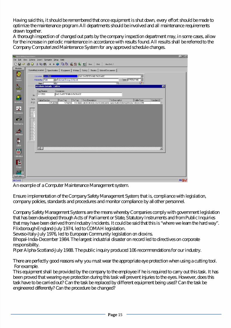
Having said this, it should be remembered that once equipment is shut down, every effort should be made tooptimize the maintenance program. All departments should be involved and all maintenance requirementsdrawn together.A thorough inspection of changed out parts by the company inspection department may, in some cases, allowfor the increase in periodic maintenance in accordance with results found. All results shall be referred to theCompany Computerized Maintenance System for any approved schedule changes.
An example of a Computer Maintenance Management system.
Ensure implementation of the Company Safety Management System, that is, compliance with legislation,company policies, standards and procedures and monitor compliance by all other personnel.
Company Safety Management Systems are the means whereby Companies comply with government legislationthat has been developed through Acts of Parliament or State, Statutory Instruments and from Public Inquiriesthat may have been derived from Industry Incidents. It could be said that this is “where we learn the hard way”.
Flixborough-England-July 1974, led to COMAH legislation.Seveso-Italy-July 1976, led to European Community legislation on dioxins.Bhopal-India-December 1984. The largest industrial disaster on record led to directives on corporateresponsibility.Piper Alpha-Scotland-July 1988. The public inquiry produced 106 recommendations for our industry.
There are perfectly good reasons why you must wear the appropriate eye protection when using a cutting tool.For example.
This equipment shall be provided by the company to the employee if he is required to carry out this task. It hasbeen proved that wearing eye protection during this task will prevent injuries to the eyes. However, does thistask have to be carried out? Can the task be replaced by different equipment being used? Can the task be
engineered differently? Can the procedure be changed?

7/28/2019 Essential Knowledge for Potential Offshore Installation Managers
http://slidepdf.com/reader/full/essential-knowledge-for-potential-offshore-installation-managers 16/101
Page 16
However if it has been found that in order to carry out this task safely, the operator must wear eye protection,how can we ensure that the operator adheres to this requirement?It is workplace legislation.It is company policy.It is part of an operating procedure.It is highlighted on his Permit to Work and part of the Risk Assessment.He has been informed of its requirement in the Tool Box talk.
There is appropriate signage at his workplace and throughout the installation.If there is adequate ventilation, at the job, he will not remove the eye protection because of misting.
Legislation, company policies, standards and procedures are produced for the continuing safety and protectionof the working man/woman and ourselves.
Promote a safety culture where all personnel have an understanding of the Operations procedures and Safetystudies and operate rigorously in accordance with them.
1. Leadership. Senior management is committed to safety. They set the example by making safety a key partof all strategic planning efforts and know safety makes for smart business actions. Maintain a safety champion
and an executive-level owner.
2. Empowerment. All employees have the right and responsibility to stop work if they see an unsafe situation,even if it compromises timelines or budgets. From day one of joining the team safety is demonstrated by thecompany's leaders.
3. Training. Safety training is required. New employees complete safety training within 30 days of beinghired. Through numerous training sessions, fairs, and luncheons at individual work sites throughout thecompany work-place accidents can be reduced. The fairs include demonstrations of safety equipment,discussion sessions and lectures on safety issues ranging from fall protection and scaffolding to hazops andwriting safety plans. All workers on the installation as well as in the office attend safety training fairs.
4. Benchmarks and Goals. Goals and objectives—such as zero accidents, no lost time, education/training,performance improvement, and attitude and commitment—are set and the team performance is tracked.
5. Incentives.Recognition programs help to foster performance improvement and loyalty as well as increasethe quality of projects. Employees work hard to maintain a safe environment and they are recognized for theirefforts and results.
Ensure strict implementation of the Permit to Work (PTW) system.
A robust Permit to Work system is one of the prime recommendations of the Lord Cullen Public Inquiry into
the Piper Alpha disaster. A permit is not by itself permission to carry out work. The permit is an indication thatthe senior management on the installation have;
Agreed that the work can be carried out within the restrictions and reservations indicated on the permit to
work. By signature.
Communicated to all related personnel that this work will be carried out at that time by that person.
Indicated that the equipment to be worked on has been appropriately prepared with reference to operating
procedures and that all hazards have been identified and precautions put in place.
Ensured that all appropriate documentation relating to the work permit, drawings, vendors manual, risk
assessment, chemical hazard sheets, job cards have been attached to the Permit.
Allocated a time for the work to be carried out.
Ensure that
all
possible
escalation
routes
have
been
identified
and
alternate
plans
proposed.

7/28/2019 Essential Knowledge for Potential Offshore Installation Managers
http://slidepdf.com/reader/full/essential-knowledge-for-potential-offshore-installation-managers 17/101
Page 17
All personnel shall be trained and tested in the Permit to Work system at the level appropriate to the individualcandidate and his position within the company. This must be seen as a statutory requirement by everyone,which shall be repeated at two yearly intervals. A Computer based training system is the best means of carrying out this requirement. The computer is impartial and it gives a ready reference for the checking of personnel who may feel that “I did that only last year, I am still in date”. Contract personnel will visit manyinstallations as part of their normal work cycle, they need to be reminded that this is the way that this companydoes work.
A permit is a certificate that prescribes areas of hazard and precautions that need to be taken. It has to berelevant for all activities on the installation and all installations across the company. As such it will not meet allthese requirements. The system needs supporting documentation. First amongst this supporting documentationshall be a risk based job safety analysis wherein all hazards associated with the particular job are identified,perhaps from a historical reference, and precautions identified that shall be put in place/utilized. The permitshall refer to this JSA and this shall be used by senior management on the installation to ascertain that theproper consideration has been given by the participants to the safety of themselves, others on the installationand to the safety of the installation itself before, during and after the commencement of the proposed work.Further supporting documentation may include installation drawings wherein the exact position of the work totake place is highlighted, any isolations required are annotated, any draining and purging points, entry points,
exit points and escape routes identified. The amount and type of supporting documentation can vary accordingto the activity planned, it must however, be sufficiently adequate and relevant that senior management are ableto make informed judgments regarding the approval or otherwise for the commencement of the work.
Permit to Work audits are the means of ensuring that work is being carried out safely to the requirements of thePermit to Work system. A simple audit off ongoing work shall provide the assurance that personnel arefollowing the restrictions of the permit as designated by JSA and formalized by senior management in signingto approve the work. A monthly audit of completed permits shall ensure that the same standards of safety arebeing sought throughout the installation and by differing crews. An annual audit by onshore seniormanagement shall ensure that corporate policy is being followed by all installations and that a Safe System of Work is in place.
Ensure all documentation and certification is in order and up to date.
It has long been the case that personnel are not allowed to travel offshore without having attained the requiredcertification to do so. The certification guarantees that the personnel have achieved a minimum standard of competence in attendance at a pre-determined series of exercises run by an accreditation centre.
It is also the case that equipment must be regularly tested, as fit for purpose and certified by accreditedspecialists. This applies significantly to all lifting equipment whether it is lifting gear, as in shackles, strops,containers, tanks or as lifting equipment as in cranes, fixed or travelling. Safety equipment requires regulartesting and maintenance. Life boats, life rafts, fire extinguishers and emergency generators are just some of the
pieces of equipment that carries an annual or biennial certification requirement.
HSE Case will specify how much and how many articles are required to meet identified hazards. For example,water based fire extinguishers in offices and CO2 extinguishers in switch rooms, where differing hazards havebeen identified. However, how many radio operators are required, and of what type, do you need a full timemedic if everyone is a trained first aider.
These are not questions that require to be answered. You will employ a medic. He may also carry out the dutiesof the Helicopter Landing Officer, Document controller and HSE advisor but, you will employ a medic. This isa slightly disconcerting trend in multi-disciplining. It has also been seen in areas where the crane driver mayalso take the role of radio operator and HLO. This use of personnel can be proved to be erroneous, as in the
case of emergency management, however it is so engrained into the management psyche now that onlylegislation will alter it.

7/28/2019 Essential Knowledge for Potential Offshore Installation Managers
http://slidepdf.com/reader/full/essential-knowledge-for-potential-offshore-installation-managers 18/101
Page 18
Documentation, yes you will be required to keep all relevant installation Operating Procedures up to date. Thatmeans having a complete library available in hard copy. You will have read and approved all of thisdocumentation and signed for it. You will also have to let Document Control know that you have received allthis information by returning a signed copy of the delivery note.
This information will be needed by the crew and the simplest way to do this is to update the computer folder onthe installation only drive. An e-mail around the departments will alert personnel to new or updated
procedures. You will need to ensure that all previous revisions of documents are no longer available as only upto date procedures can be used to support Permit to Work.
Document control as part of a document management system is driven from onshore. It shall provide the meansof disseminating legislation, policy, procedures and in some cases vendor manuals.
The Company Computerized Maintenance System shall contain all the required information regarding regularcertification periods of equipment. This system will flag up the need to re-certify equipment as part of aplanned maintenance routine. Some of the systems currently in use are Maximo and SAP. Installationtechnicians will not generally have the appropriate qualifications to re-certify equipment such as liftingequipment, fire extinguishers, life boats and other safety equipment. Specialist vendors will need to be
contacted to carry out this certification.
LEADERSHIP, DEMEANOR & PERSONALITY PROFIL ING
Facilitate constructive working relationships with all personnel encouraging open communication, bothvertically and laterally.
Traditionally leaders were either elected or fought for their position through conflict, the position of OIM is aleadership position it has since the Piper Alpha been a position of Authority & Responsibility, by definitionAuthority is a single voice this is not a democratic society we live in offshore, there has to be a strong structure
which will not fail, a chain of command and report ability, especially relevant when dealing with emergencysituations offshore, Responsibility means you will be held accountable for the outcomes be then good or poor,having said that we need to ensure harmony amongst the personnel onboard, the best way to explain this is byusing a metaphor, the one I like to use is we must take on the position of the “coach of a football team”(mentoring position) years ago we were taught to be the captain of the team and physically play the game, it isvital now that we lead from the side line, getting the best from our team is by distancing our selves from themto the side line, the position of the coach still has you on the field but in a more commanding position capableof seeing the big picture and focus on all aspects of the game. We have effectively shared the authority to actbut retained the responsibility for outcomes obtained. Let me ask you a simple question when did you lastattend a leadership course or program, for some of you never would be the answer, we tend to associate leaderswith personnel from the military, police or fire services, people who work under a rank system, from personal
experience each time I was up for promotion I had to be assessed within my chosen skill (profession) thenattend a leadership program which taught me how I must now react & report to those above me and below me,this course bore more weight than my skills exams, yet in the Oil & Gas industry as with many industries thereis no such leadership program available for managers as they take the giant leap from operator to supervisor
I am not saying that ex-military or uniformed personnel make better leaders on the contrary they often makepoor leaders, what I am saying is as a leader we must know how to delegate, motivate, & most importantlycommunicate. A good communicator will ultimately make a good leader, think about that a while, look atleaders of countries the ones who achieve the most are those who will listen and speak with authority, a strongleader can lead anyone. A good leader can develop a workable strategy and with applied tactics achieve asuitable outcome to any situation, the magic word that will link strategy (planning phase) with tactics (action
phase) is communications, we are not looking for acceptance or every one to agree with our plan we are

7/28/2019 Essential Knowledge for Potential Offshore Installation Managers
http://slidepdf.com/reader/full/essential-knowledge-for-potential-offshore-installation-managers 19/101
Page 19
looking that they understand why we are doing this way and what their part to play in the plan is, we can this justification.
Leadership relies on getting things done in a climate of two-way communication and trust. True leadership
develops ownership in the team and is empowered by directing individual energy towards the common goal.Support of the team by the leader is critical to the success of the team’s performance. Team memberssupporting each other will work as a cohesive unit not individuals. The ethos of team support starts frommanagement to leader to team member. A leader’s support of the team must be shown by deed and stated whenrequired.
An effective leader will forge a close relationship between team members and themselves. An effective leaderwill foster an environment of continuous improvement that encourages individuals to perform at their best andstrive to be better. The greatest challenge to any leader is to understand what motivates a particular person. Aleader must aim to create an environment that challenges an individual and the team by establishingbenchmarks. Once a benchmark has been met the leader must review the performance, provide feedback andestablish a new goal in agreement with the team.
Effective leadership is recognized as being:
Future orientated
People focused
Principle centered
Achievement motivated
An example of a good supervisor is someone that never assumes that his people know that they are doing agood or below average job. When people know that their Supervision or work colleagues will pick them up ontheir at risk behaviour they tend to monitor their behaviour and consequently change how they do things.

7/28/2019 Essential Knowledge for Potential Offshore Installation Managers
http://slidepdf.com/reader/full/essential-knowledge-for-potential-offshore-installation-managers 20/101
Page 20
Promote team building, training and development and to ensure that the Company Competence AssuranceSystem is progressed.
Personnel who are employed in the offshore environment have their homes in all quarters of the country. Theonly ties that many have with the company are when they gather for the trip offshore from the heli-base. Thisway of operating can impose an unacceptable lack of understanding amongst personnel who must face the nextfourteen days or more in a tight environment where personal habits and personality traits may cause
unnecessary tensions. This can be the basis for unacceptable working practices and potentially unsafe actions.It is the OIM’s task to identify these tensions and take action to relieve them. He must attempt to promote anatmosphere where good team work is encouraged and a safe working environment fostered.
Team building activities are an acceptable method of gathering personnel together in a non-offshoreenvironment. None of the offshore tensions are apparent beyond the interpersonal relationships. This is thespecific function of Team Building exercises. To provide an environment whereby personnel may achievecertain pre determined tasks of an innocuous nature which by their non confrontational nature encourage closecooperation between personnel. When these activities, with a high achievement level, are carried out in a nonthreatening environment by personnel who also work together on the installation, an opportunity is being givenfor new alliances to be made and good working practices between personnel encouraged.
Team building is not training, training is an expansion of knowledge that may be academic or work related. Itis in the company interest to provide training for personnel whether it is to raise the educational level of theworkforce by academic excellence or provide vendor training of new equipment (or old equipment that is notunderstood). It provides a level playing field of knowledge. There is a natural turnover of staff in everyindustry. Sometimes it is felt invidious that training is expended on personnel just to have them move on andtake that information with them. Remember you are not the only industry faced with this problem. Where hasyour workforce come from? Education levels are not a means of ensuring that personnel are capable orcompetent. Training is a means of providing a known level of understanding for everyone. Assessment is themeans of testing that level of understanding.
In order to assess competence we must establish targets. These targets are the levels of knowledge that weexpect the workforce to have achieved in order to perform their work effectively. These targets will be set bydiscipline experts; OIM, Operations managers, Supervisors. The form that this knowledge takes will be welldefined.
Intimate knowledge of a particular procedure can be tested by question and answer sessions or testing.
The lineup of a piece of equipment shall be tested by a demonstration of the activity.
This opportunity may be taken as part of an actual line up or as a simulated activity which is observed and
assessed.
A witness statement by a fully assessed individual or a supervisor shall also provide adequate recognition of
competence for assessment purposes.
The knowledge set of the elements shall be grouped, as related, in Safety awareness, Emergency procedures,Fault finding, Operational knowledge, Administration and such headings as shall be relevant. Theappraisal of the workforce knowledge, as set by the standards, shall be carried out by a trained and approved assessor. Thiscan be someone who is part of the workforce but by nature of his experience and maturity may not take anactive development role but by his impartiality is uniquely qualified to carry out this assessment and mentoringrole.

7/28/2019 Essential Knowledge for Potential Offshore Installation Managers
http://slidepdf.com/reader/full/essential-knowledge-for-potential-offshore-installation-managers 21/101
Page 21
TRAINING & STANDARDS
There are a number of courses each person must do before they can proceed offshore to work, many of thesesafety related courses stem from the lessons learnt in 1988 from the Piper Alpha disaster, along with themandatory safety training courses, each person is to be suitably trained and proficient in their trade be itcooking in the galley, erecting scaffolding for painters right through to managing the process machinery andequipment essential to refinement of the product, at the top of the training tree we have the OIM and hiscourses, once again we go back to the Piper Alpha and the identified need for OIM to hold a recognized levelof proficiency in leading teams during an emergency situation on an offshore facility, this course is commonlycalled the MOME (Management of Major Emergency) course where candidates are put through their paces indecision making, working under stressful situations, and planning, this is what Charlie and I have been doingfor most of the super major oil companies around the world for the past 8 years.
Along with the mandatory safety training such as HUET, BOSIET, Fire Training and now OIM MOMEtraining we are seeing an increase in Legislative training awareness, this is a customized program for offshoremanagers to understand the legal framework of the area they are operating in, we have started conducting thesecourses recently, these programs have been in place in Europe for a number of years but as we are expandingout of Europe to other continents we are seeing legislation courses being developed and presented to managersoffshore they cover a wide range of subjects such as local environmental laws right through to loss of lifewhilst at work and the legal frame work of accountability, these have popped up after the incidents in Americaon onshore refiners were seen to be poorly managed by the onsite managers, it is a program to protect andensure the understanding of managers not to apportion blame, blame is a poor word for a consequence thatresults of a failure in either a system or a person. The following is an insight into some globally recognized
standards and how they are conducted.
He shall ensure that regular Emergency Response Drills are carried out in compliance with regulations.
In 1991, the United Kingdom Offshore Operators Association produced a set of guidelines for offshoreemergency response training (UKOOA, 1991). It states that Offshore Installation Managers and their Deputiesshould:
Have a good working knowledge of the installation operations.
Be well versed in the installation’s emergency systems and procedures.
Be aware, on a day to day basis, of particular operations and special circumstances approved under the permit
to work system which may affect the ability of the installation to respond to emergencies.

7/28/2019 Essential Knowledge for Potential Offshore Installation Managers
http://slidepdf.com/reader/full/essential-knowledge-for-potential-offshore-installation-managers 22/101
Page 22
Be trained and be able to assess and to control developing emergency situations with the objective of
safeguarding personnel and the installation.
Be able to act as coordinator between the installation and the onshore and offshore responses to the
emergency.
Be able to act as on scene commander where a serious incident occurs on a nearby installation.
These guidelines are as relevant today as they were then, in the wake of the Piper Alpha enquiry. During theincident, personnel gathered in the accommodation because that is where they had been trained to expectassistance to arrive. Those who used their initiative generally survived those who didn’t, do. Nobody ever toldIan MacIntosh (Radio Operator) that he could survive a jump from the helideck, 200 feet above the water. Infact it was perceived wisdom that he would not. (10 days later he was on the Claymore working for me).
The regulations state that emergency response exercises shall be carried out every week. I do not consider amuster drill as an adequate emergency response exercise. Once a week is little enough time to spend on whatmay prove to be a life saving exercise. The installation management should generate a series of crediblescenarios that are relevant to their own installation. These scenarios should be carried out on a regular basis totest the response of teams, individual personnel and the understanding of installation alarms and shutdownsystems.
The offshore oil industry has clearly accepted the recommendations made by Lord Cullen on the need toensure that their offshore managers are competent to handle emergencies. The development of a standard of competence by OPITO on Controlling Emergencies for OIMs has provided a valuable focus for those taskedwith reviewing selection methods, improving training and establishing formal competence assessmentprograms.

7/28/2019 Essential Knowledge for Potential Offshore Installation Managers
http://slidepdf.com/reader/full/essential-knowledge-for-potential-offshore-installation-managers 23/101
Page 23
There is still a need in some organizations to formalize and document procedures of selection and appraisalparticularly with respect to emergency command responsibilities. Offshore training organizations andconsultants appear to be working with the industry to refine and develop both selection methods and the qualityof training provision.
One of the difficulties of defining selection criteria and conducting training needs analysis for the OIMpopulation as a whole is that they manage a wide range of installations with very different operationaldemands. It would seem entirely appropriate that the assessment of their competence to manage an emergencyis based on the type of emergency they are likely to have to manage, that is in relation to the safety case of aparticular installation.

7/28/2019 Essential Knowledge for Potential Offshore Installation Managers
http://slidepdf.com/reader/full/essential-knowledge-for-potential-offshore-installation-managers 24/101
Page 24
Simulations of emergency exercises can take one of the following formats: Simulations can be conducted offshore, usually orchestrated by external consultants presenting the control
team members with an unseen emergency scenario.
Onshore simulations can be conducted within purpose built premises, with high fidelity equipment to mirror an
offshore control room or radio room, other key offshore locations, and communications equipment.
Onshore table‐top scenarios are another form of exercise, often conducted in a number of rooms to represent
different offshore locations, with telephones and portable radios to represent offshore communications
systems. Onshore simulator:
The purpose built simulator contained three rooms; a control room with white boards, telephone, radios, PA,
platform alarms and fire and gas status information,
a radio room with radios and telephones, and
A fire team or response team leader's room.
The control room is under video surveillance. The trainers can produce a platform alarm, power failure,
communications breakdown, fire and gas information, sound effects and can control all equipment in the
simulated control room.
The offshore control team can be gathered together to role play their own, or others' offshore positions.
The simulator can be based on a mythical fixed platform or a real installation, and the POB list, offshorecontact personnel and scenario can be organized to reflect the installation participants usually work on. Theexercise aims to enhance the following skills:Model making (being able to mirror in one's mind what is happening at the scene of the incident),
Pre-planning skills, information gathering, planning, problem solving, decision-making, delegation, andCommunication skills.

7/28/2019 Essential Knowledge for Potential Offshore Installation Managers
http://slidepdf.com/reader/full/essential-knowledge-for-potential-offshore-installation-managers 25/101
Page 25
The scenarios usually last for up to one hour, run in 'actual time elapsed' in scenario development. That is,although participants are asked to imagine a start time (e.g. 6 a.m.) time elapsed thereafter is at actual pace.After each exercise, a structured feedback session is conducted, with each of the main response groupsproviding constructive comment on other groups' behaviour.
Onshore table-top: The table-top scenario was located in two separate rooms, with a written emergency scenario for participants to
follow based on a real platform. Two offshore locations, the control room and scene of the incident were imitated by placing staff in twoseparate rooms. Portable radios and telephones imitated offshore communications systems. Participants werefaced with various unseen written scenarios ranging from a general work situation fire to a major offshore oiland gas emergency.Offshore scenarios were written to match the type of installation the participants worked on, but were not runin real time. The offshore control team role played their own and each others posts during theseScenarios. The exercise aimed to provide participants with knowledge of their company's emergencyprocedures, onshore support and the role of the emergency services, and decision making in stressfulsituations.
There was no assessment of participant’s performance by the course trainers but feedback was provided.

7/28/2019 Essential Knowledge for Potential Offshore Installation Managers
http://slidepdf.com/reader/full/essential-knowledge-for-potential-offshore-installation-managers 26/101
Page 26
Each type of scenario presentation has its own merits and weaknesses. The simulator is essentially generic butit can be purpose built to the specifications of a single installation; also it can be adapted for particularinstallations by using their station bills, telephone numbers and their emergency response procedures.It can also provide a convincing degree of realism in simulating the offshore environment which a table toppresented scenario cannot do.A simulator also does not suffer from the distractions often present in hotel rooms or in the company officesand can therefore usually elicit more realistic responses from participants and generate a more stressful
atmosphere.An advantage of both types of onshore simulation is the opportunity to simulate major offshore emergencies(e.g. blowouts and explosions), and the degree of control the trainers have compared with an offshore location.What both types of onshore exercise lack is practice in using the equipment of the participants' installation, andany advancement of their knowledge of the installation and the responses of crew members apart from theemergency control team. It appears that there are probably merits in using both onshore and offshore exercisesto train OIMs in emergency command.
The OIM shall ensure compliance with any obligations laid down in the Installation Collective BargainingAgreement.
This is a feature of the way that individual countries deal with offshore remuneration packages for theirworkforce. In some countries this will have been achieved through long discussion and possibly arbitration.
This may involve how individuals are treated in the offshore environment. Hours worked and rest periodsbeing taken into consideration. It may be necessary for the OIM to enter hours worked into the Installation LogBook. This is a function that will definitely vary with location.
The OIM shall provide relevant reports to the Concession Owners representatives as per their requirements.
“Time is currency”. Take time to ensure the information that you present to your company or client is correct.Far reaching decisions will be made based on the figures that are produced from your installation.I asked an OIM of an FPSO recently, why there were no off load meters on board the installation. Hesuggested that the tank dips and the figures from the shuttle tanker would be adequate. I must admit that I washorrified by this level of complacency.
Today, levels of atmospheric emissions of vent gasses from toilets are monitored so that greenhouse gasemissions are more fully accounted for, for example.

7/28/2019 Essential Knowledge for Potential Offshore Installation Managers
http://slidepdf.com/reader/full/essential-knowledge-for-potential-offshore-installation-managers 27/101
Page 27
In the oil industry there are many vested interests. As an OIM you are not only responsible for the personnel onyour installation you are also responsible to every single share holder in the company that pays your wages. Itis a very rare situation, world-wide, where a single company owns the oil in the ground, the facility producedto, the means of transportation, the refining capacity and the downstream sales outlet.Consider this, a mature oil production platform on the UKCS. Originally owned equally by 4 major companies.
The platform is tied into a pipeline to onshore also shared by 4 other facilities one of which is also a partner. The operator decided to carry out some development drilling on a promising block nearby. He looks to the
industry for some venture capital to spread the financial risk. 5 small institutions risk some money in thisenterprise. The field is proven and several wells are developed and tied back to the mother platform. This is aseparate field and requires a facility built on the mother platform to process the hydrocarbon for shipment. It isa prolific find and extends the life of the mother platform considerably. One of the major shareholders decidesto sell out as there are some troubles at home and 10 new shareholders join the club. What do we have now?We have a facility that has a main partner owning about 25% of the production and many small companiesowning as little as 1% of production. In fact some of the small companies may only own the production fromcertain wells.Now tell me that you think you will rely on tank dips.As the senior manager on the installation you will know exactly how much your facility can produce on anygiven day. Y ou will be confident that the numbers you divulge to partners will be correct, to two decimalplaces. Your metering will be correct and it will be checked on a regular basis. Your meters will be proved byusing meter provers. Variables that affect these meters shall be monitored and minimized as much as ispracticable. Water cuts, the amount of water produced from individual wells shall be minimized by separationand disposal. Scale deposits, calcium carbonate from the formation dropped out when pressure drops areexperienced, shall be minimized by the addition of chemical scale inhibitors. Temperature, pressure, densityare all factors that influence meter accuracy. As such compensatory adjustment will be made for these factors.Monitoring of these factors really is the job for an accredited third party.I have already mentioned atmospheric emissions; this has much to do with your carbon footprint. If your poweris generated by thermal engines, not windmills, then you will know how much CO2 they produce when in use.What might not be so obvious is the amount of carbon emission from diesel tank vents for the emergency fire
pump motors. Someone will require this information on a daily basis.How many people do you have on board? They all require to be fed and looked after. If everyone works for theparent company there is not a problem. Do you have contract staff on board? How many and how often? Istheir food and board part of your company’s responsibility? Of course it is, but there must be trueaccountability for this. Part of your report.Downtime. There is no allowance within the production targets for downtime. Any planned maintenance thatrequires plant to be taken out of action, off-line, affecting production must be identified as deferred production.
This will be acceptable to the specialists onshore who may only see the “bottom line”. Deferred production isidentified by some companies in one way and by other companies another way. There is no rhyme or reasonfor it but one company will consider oil that is not produced today as lost oil, whereas another company willsay that they can get the production back over an extended period. Find out your companies viewpoint and try
to adhere to it.All installations are subject to the annual shutdown, this may take place every six months or every two years orany period in between. This can be a bit of a head ache for the OIM. You will have lost one of your best menfor several months while he pulls together a shutdown plan with the beach bound planning team. All of those
jobs that have been deferred to a suitable shut down time will be presented for inclusion. Vendors will putforward modifications to their equipment that must be carried out at this time. Installation modifications mayalso be planned for this period. All of this activity also puts enormous pressure on that most finite of resources,bed space. Make sure that part of the plan includes numbers required on the installation in excess of the normalworkforce.
The future of how we record things and report to people is finally coming in line with how others do it ashoredue to our location and the challenges faced with getting to and from us we are seen as remote, however we

7/28/2019 Essential Knowledge for Potential Offshore Installation Managers
http://slidepdf.com/reader/full/essential-knowledge-for-potential-offshore-installation-managers 28/101
Page 28
have seen the introduction of the VDR (Voyage Data Recorder) on marine vessels, this was initially to be apanic button concept but has evolved into more of a “black box” down loading vital data pertinent to location,movements, machinery and personnel data to authorities 24/7.
I have personally designed and registered such a piece of equipment that does this and much more, but due tothe sometimes dinasouric nature of our industry it is too much too early, having said that I am seeing youngerOIM candidates come on line, these are the people who have grown up with using a laptop in school, I live by
a famous quote, “Simplicity is the art of making the Complex clear” going further down the IT highway iswhere we are headed, I have enclosed some pictures of my software that is in use offshore now with some of my clients and working as a fit for purpose tool, the goal was to support managers in their processes not tohinder them in any way.

7/28/2019 Essential Knowledge for Potential Offshore Installation Managers
http://slidepdf.com/reader/full/essential-knowledge-for-potential-offshore-installation-managers 29/101
Page 29

7/28/2019 Essential Knowledge for Potential Offshore Installation Managers
http://slidepdf.com/reader/full/essential-knowledge-for-potential-offshore-installation-managers 30/101
Page 30
QUALIFICATIONSAcademic Achievements.
You do not need a degree to be an OIM. Having the discipline required to gain a degree would certainly be of benefit to a candidate for the position of OIM. The position of OIM requires a very broad spectrum of knowledge to successfully handle all eventualities. The ability to express oneself confidently on many levels is
a more valuable quality. A relevant technical qualification in a science or engineering discipline is a valuableresource for the aspiring OIM. Any company that employs an OIM will have recognized the ability of an OIMwhether he has a degree or not. Any company that requires a degree can provide the appropriate candidate witha suitable training program to meet that requirement. Academic qualification is not a direct indication of abilityto do the job.
Vocational Qualifications.
Offshore survival/firefighting with HUET. This is the standard course, for all personnel working offshore, held at many centers throughout the oil exploitation regions. A four day course for the initial exercise
and then two day refresher courses at four yearly intervals. The course is a basic entry level
comprising first aid, survival techniques, helicopter use, emergency actions and life raft boarding in an
environmental pool. Fire fighting is restricted to limited use of fire fighting techniques in carefully
controlled situations. HUET is an acronym for Helicopter Underwater Evacuation Training. As it
suggests it is training in how to escape from a helicopter that has ditched in the water. Even when the
helicopter is upside down. Use of a rebreather which allows the wearer to breathe while underwater
for an extended period, out with holding your breath.
Permit to Work Course, in this case Level 3. This is a training course which will be run by the HSE department of any oil company. All aspects of the Permit to Work are dealt with in minute detail. The
OIM will be required to pass the final exam with the absolute minimum of mistakes. For an OIM I would suggest that a pass mark of 90% is required.
Oil Spill Response. A strong working understanding of OSR organizations such as PIMMAG and EARL and
your involvement and accountability to report, monitor and reduce contamination to the
environment.
Emergency Management and assessment, as covered in this book in the relevant section. OIM Regulations. As the manager of an offshore oil production facility you are obliged to be aware of
all the relevant legislation associated with the function. There are courses available that deal with
this, very dry subject. The intensity with which you are bombarded by this subject will depend on the
national curriculum that is in force. This is presented differently in different states. Reading material
that I would suggest should include. The Health and Safety at Work Act in your country. Safety of Life
at Sea. ISM Code. COSHH Regulations. Marpol. ISPS Code. Safcon. MODU Code. This is a very brief and
non‐exhaustive list which does not include areas that I consider important such as, Oil Spill Response.
Search and Rescue. Dangerous Goods Transport.
ACCIDENT & INCIDENT INVESTIGATION
1.1 All accidents, incidents and dangerous occurrences should be investigated in the first instance to find outwhat happened and why it happened in order that measures can be taken toprevent a repeat of this or asimilar accident.1.2 Investigation of accidents should also be undertaken for the following reasons:
a. To ensure that all accidents are properly dealt with.b. To identify the causes and apply remedies to prevent a recurrence.

7/28/2019 Essential Knowledge for Potential Offshore Installation Managers
http://slidepdf.com/reader/full/essential-knowledge-for-potential-offshore-installation-managers 31/101
Page 31
c. To demonstrate the positive approach to Safety Management Systemd. To identify accident trends.e. To determine the accident potential for major loss.f. To comply with Statutory Legal Requirements.
2. ACCIDENT INVESTIGATION PHASES
2.1 All accidents involving injuries to persons and damage to plant or equipment should be thoroughlyinvestigated so that immediate action can be taken to prevent recurrence. The following may be useful as aguide to the steps to be taken:2.2 The steps of an investigation are as follows:1. Initial Response.2. Establish Facts. 3. Analysis
4.Short Term Preventive Action.
5. Recommendations.6. Reports. 2.2.1 It is items 2, 3 and 4 that we must concern ourselves with directly. These steps are the ones requiringknowledge and skill for their safe and successful execution.2.2.2 They are inevitably the responsibility of the managers and supervisors carrying out the work and theymust put themselves in a position where they can meet the very serious requirements of their responsibilities.
This can only be done if Pre-planning is carried out by all concerned.2.3Pre-Planning.2.3.1 It is true to say that the first actions in an Accident Investigation take place long before the accidentoccurs. This action ispreparingfor such an accident.
Naturally, the company will have carried out the Statutory Risk Assessments and will have done everything toprevent accidents from happening. Nonetheless, mitigation is most important and being prepared is far betterthan attempting to get things right when under the pressures of a real emergency.2.3.2 We may be aware that the Government Enforcing Authority will be arriving and carrying out their owninvestigation. It may be Company Policy that a Head Office Team will carry out Accident Investigations. It isnonetheless vital that the people on the spot carry out those actions that will prevent re-occurrence in the shortterm. Provided we do not contaminate evidence or interfere with their activities, we are fully justified and wiseto conduct our own local investigation.2.3.3 The Manager responsible should establish sufficient Accident Investigation Teams. He should brief eachteam regarding the areas they may be required to carry out investigations in, should there be an accident there.
These teams will need to train and rehearse their roles in the event of an accident.
2.3.4 Ideally the teams should be made up of a Senior Supervisor from one Department, a less seniorSupervisor from another Department and say three Safety Representatives. The second Supervisor should havea nominated replacement in case the accident occurred in his own department.2.3.5 The Installation Manager should not head up the Investigation Team if at all possible. He should reservehimself for approving or otherwise the team's report and recommendations. After all, the accident will haveoccurred in his area of responsibility and he may not be totally objective during the analysis.2.3.6 For similar reasons, the Safety Advisor or Safety Officer should not be part of the Investigation Team. Heshould be available to give advice to the team and the Manager but should not be lost to the overallinvestigation by getting involved in the detail.2.3.7 Each team will normally be familiar with one another and with those Areas and Departments that they
might be required to investigate in the event of an accident.

7/28/2019 Essential Knowledge for Potential Offshore Installation Managers
http://slidepdf.com/reader/full/essential-knowledge-for-potential-offshore-installation-managers 32/101
Page 32
2.3.8 Any uncontrolled event is an accident. It may be called an incident in some circles, but if it was notintended then it was accidental. There is no such thing as an unimportant accident. The results of an accidentmay be classified as 'minor' but this in no way means that the accident itself is minor. The 'ripple effect' of anapparently minor accident may have serious consequences if not properly dealt with.E.g. the infection that started from an unreported minor cut may be able to lead to the amputation of a limb.2.3.9 The unreported accident becomes a 'time bomb' waiting to be detonated. The next time, this unimportantevent occurs, the consequences may be disastrous.
Incidents, Near misses, Dangerous occurrences or any uncontrolled event is an opportunity. It is an opportunityto:a. Prevent re-occurrence and possible escalation.b. Train the Accident Investigation Teams in the various skills they must acquire.2.3.10 getting good at Accident Investigation needs effort and application. Senior Management should makethe resources available to allow these various incidents to be properly investigated. Doing this can change theculture of the work force. In studying Accident Investigation, people become aware of Accident Preventionwhich seems to occur more naturally.
2.4 Initial Response2.4.1 Whenever an accident occurs, personnel in the vicinity will immediately respond in accordance with theirindividual training. If injury is involved, First Aid and the Medic, Nurse or Doctor will be summoned and theappropriate care administered.2.4.2 The danger is that what has just happened might escalate. So when the expression"secure the site" isused, it means four things:a. Attend to injured persons.b. Ensure isolation of equipment and safety of plant.c. Ensure that nothing is disturbed.d. Segregate witnesses to prevent collusion before they make their statements.2.4.3 At this point the Accident Investigation Team should be mobilized; with the plant shut down they will be
aware that they are required. The team leader should take charge as soon as possible. The person in charge of the area should be aware that this is going to happen and hand over to him as appropriate and as soon aspossible.2.5 Establish the Facts.2.5.1 Facts are established in many ways. It is important that those members of the Accident Investigation
Team, employed to collect these facts achieve the following:a. Collect ALL the Facts.B. Ensure that those Facts collected are TRUE and not distorted or misleading.c. Do NOT allow themselves to leap to premature conclusions. This will prevent collection of ALL the facts.2.5.2 The methods employed to collect the facts include:a. Inspection of the Site. Photographs, Notes and Sketches.
b. Interviewing Casualties, being discrete, but gathering as much information as possible.c. Interviewing eyewitnesses. Taking Statements for later analysis.d. Interviewing the Persons in Charge of the Area and the Operation.e. Collecting Samples if applicable.f. Recording Environmental Conditions including Weather, Temperature, Lighting, Surface Wetness,Slipperiness, and Humidity etc.2.5.3 Interviewing is a most important part of Fact Collection. It is very difficult to hit the ideal atmosphereespecially under the tensions that might prevail. The interviewer should consider two important factors:a. NOT to allow the interviewee to lead to an early conclusion.b. NOT to antagonise the witness but to be sympathetic and just ‘Collect the Facts’.

7/28/2019 Essential Knowledge for Potential Offshore Installation Managers
http://slidepdf.com/reader/full/essential-knowledge-for-potential-offshore-installation-managers 33/101
Page 33
2.5.4 The Police inject one important factor. If a death has occurred, it may still be desirable for preliminaryinvestigation to be achieved by those responsible, but care should be takennot to contaminate evidence.Witnesses should be asked to write statements themselves, without the assistance of interviewers.When this "uncontaminated" statement is completed, it is perfectly all right to interview the witnesses and tofill in the gaps in a separate statement.3. INVESTIGATE PROMPTLY3.1 The sooner the investigation is started the better, provided it is safe to do so.
Delay may lead to non-availability of vital witnesses. Witnesses may discuss evidence and be influenced byother interpretations.3.2 Engineers and managers will be anxious to find ways and means of repairing damage, but their first priorityshould be to establish the cause of the accident.Evidence may be disturbed or tampered with.3.3 Safety specialists and supervisors will be concerning themselves solely with the safety implications andpreventing recurrence but if they do not know the cause they may enhance the risk of a similar accidenthappening.3.4 It is important that the investigation is properly supervised and organised.Extreme care must be taken not to disturb the workplace or machinery until the appropriate authority has givenpermission for the site to be disturbed. Failure to observe this might comprise a serious breach of the law.4. THE INJURED PERSON4.1 Certain basic facts about the injured person(s) have to be recorded. In addition to employer records, thefollowing details are required:a. Full name, sex and age of injured person.b. Company Employee Number and Department.b. His or her permanent address.c. Marital Status.d. Job Title or Normal occupation.e. Date and time of accident.f. Date and time of commencing and ceasing work.
4.2 Interviewing the Injured Person.4.2.1 This should be an early priority; even the briefest description of the accident should suffice initially.4.2.2 The physical and mental state of the injured person will need to be considered and tact and patience maybe required during the interview. The injured persons should be in a fit state to answer questions coherently.4.2.3 The patient should be encouraged to talk about how the accident happened and it is important that he hasconfidence and trust in the listener. Any hint of a "company cover up" or "self blame" must be strenuouslyavoided.4.2.4 Questioning should not take the form of an interrogation. Someone well known to the injured person islikely to be the best person to communicate with him.Do not be surprised if he did not see anything.5. INTERVIEWING WITNESSES
5.1 Tact, patience and skill are required when interviewing. Witnesses should be interviewed as soon aspossible after the incident, before they talk to others. They should not be isolated for more than five or sominutes before the interview starts. When people talk to others, or when they sleep, they edit theirMemories. Their recollections should be recorded before their memory changes.5.2 Witnesses should be interviewed separately and privately. The witness should be put at ease. If the witnesswishes to say anything or talk about any matter before notes are taken, they should be allowed to do so. Theinterviewer should select a setting that is comfortable to the witness. Walking through theFacility or the site of the incident can sometimes be satisfactory.5.3 There are many methods used when interviewing. Some like to use two interviewers, one conducting theinterview while the other takes notes. This is a bit heavy on resources, especially when there are a lot of
interviewees and often causes the witness to be a little nervous. One on one is recommended along with the use

7/28/2019 Essential Knowledge for Potential Offshore Installation Managers
http://slidepdf.com/reader/full/essential-knowledge-for-potential-offshore-installation-managers 34/101
Page 34
of a tape recorder. This makes for an interview unhampered by note taking while the witness is talking andallows a "second cut" before the statement is finally made.5.4 The witness should be put at ease at the start and it should be emphasized that the objective is fact findingnot fault finding. Statements from witnesses should contain such details as date of birth, employer, companyID, job title, home address and telephone number etc. and the time and date of theInterview should be indicated at the end of the statement.5.5 Skilled interviewers will allow witnesses to tell things in their own way, only to prompt and to elicit
answers where necessary. Questions should be impartial and should be recorded together with the answers. Theinterviewer is only the conduit through which the Facts will be passed. He is only there to assist the witness torecall and record the facts. If he is not doing this he becomes a negative element in the process.5.6 Open ended, non-leading questions should be asked. For example, "What did you see next?" NOT "Wasthat when the pipe fell?" It is a good trick to try and avoid using "you". If it is not used, the interviewee cannotbe accused or attacked. Always remember, his objective is to gather ALL THE FACTS. He should avoidmaking the witness feel threatened or resentful. The good interviewer will show respect, gaining his confidenceand extracting facts.5.7 Interviewers should seek answers to the following basic questions:a. What did the witness see, hear, feel, smell or taste?b. What was the witness doing at that time?c. What was the proximity of the witness to the accident or occurrence?d. What actions did he take?e. What actions did others take before and after the accident?f. What was the condition of the workplace at the time?g. What hazardous or unsafe conditions existed?h. What unsafe acts were performed?I. The probable cause(s) of the accident or occurrence. The interviewer should have a checklist to ensure thatall of those answers are obtained. If the witness offers the information without being questioned then there isno need to ask the question.6. QUESTIONING THE PERSON IN CHARGE
6.1 The person in charge may be the injured person's supervisor or manager, the person in charge of theworkplace where the work was being carried out, or both.6.2 The normal jobs and tasks of the injured person should be established from the person-in-charge. Inparticular whether the activity that led to the accident was part of the casualty's normal job requirement.6.3 Examples of questions, which may be asked, are:a. What task or type of job was being performed?b. Was it planned or part of a planned activity?c. At what stage of the work did the accident occur?d. Was the person involved in these activities trained and if so, when?e. Was the person authorised to carry out that type of work or to use machinery in that location?f. What instructions had been given?
g. How many other people were or should have been involved in the activity?h. Was the activity or task covered by statutory regulations, a code of practice or company procedures?I. Were correct and safe procedures being observed?
j. Did an unsafe act cause the accident?k. Did an unsafe condition contributed to the accident?l. What safety equipment or protective equipment was available and in use?m. Were other contractors' employees or plant and machinery involved?n. Had the injured person been in previous accidents?
7. INSPECT PLANT FOR MISUSE AND DEFECTS
7.1 Inspection of plant immediately after an accident may reveal signs of misuse or defects, which may or maynot have contributed to the accident.

7/28/2019 Essential Knowledge for Potential Offshore Installation Managers
http://slidepdf.com/reader/full/essential-knowledge-for-potential-offshore-installation-managers 35/101
Page 35
7.2 Assistance from specialists or persons directly involved or familiar with the type of plant or machinery inquestion can provide information not obvious to a person without expert knowledge.
8. DOCUMENTARY EVIDENCE8.1 May be provided to support the truthfulness and accuracy of the evidence already given. The confirmingevidence may take the form of,a. Site records.
b. Plant maintenance records.c. Written procedures.d. Work schedules.e. Work permits.f. Safety instructions.g. Inspection reports.h. Accident reports.I. Other safety reports.
9. ANALYSIS.9.1 This is the point when the Accident Investigation Team gathers together in a Private place, away from allwitnesses and others that can interfere with their train of thought. It is important that the Team Leader takescharge. He is the person who will make the report, assisted by the members of the team and possibly otherswho have expertise in specialist areas. Before the formal analysis commences, it may be useful to establish theSequence of Events and to record this sequence for later reference.9.2 Evidence gained from interviews and from inspection of the workplace, plant and equipment, should givean indication of the sequence of events leading up to the accident. Those events should be written down in thechronological order of their occurrence. This is sometimes called the Time Line.9.3 This process is not only useful for later reference and analysis purposes, but it allows all of the teammembers to become familiar with the available facts and their relevance at different points in the lead up to theincident. They will have been concentrating on the task they were given by the team leader and will not have
been aware of all the facts collected.9.4 A description of the accident should be agreed. This description should encompass the whole accident buttake only one sentence to achieve this.E.g. the unstable stones in the bank rolled into the ditch causing the worker to lose his balance and fall,breaking his leg and fracturing his collar bone. 9.5 This is where the analysis starts. The analysis can take the form of aCausationor Why Tree. The accident statement is written in a rectangle at the top of a chart and the questionwhy? Is asked. Thefactsare inspected and those that fit or answer the questionwhyare recorded in rectanglesbelow.
This is the beginning of our Tree. It is useful to achieve this tree in the first instance using Post-it Notes. Theyare easily moved about for further analysis.
If they are not available, then ordinary pieces of paper cut up to manageable3' x 2' tickets can be used.9.6 Those first answers to the questionwhyour Primary Causes are. There may be three or four of these or onlyone. Primary Causes are sometimes called Basic Causes, Immediate Causes or Principal Causes.9.7 Now, each one should have the questionWhyapplied to it and the answer derived from our list of facts.Again, there may be more than one answer to each question, and these should be recorded. These are theSecondary Causes. They may be called Underlying Causes or Contributory Causes. This process can continueuntil there are no more facts to be used. TheWhy Tree isa most useful tool for writing the AccidentInvestigation Report, but most of all it leads us to make recommendations to prevent recurrence of the incident.9.9 Types of Causes. Three types of causes are generally recognized:
1. Human Error2. Physical Cause

7/28/2019 Essential Knowledge for Potential Offshore Installation Managers
http://slidepdf.com/reader/full/essential-knowledge-for-potential-offshore-installation-managers 36/101
Page 36
3. System CauseHuman Error means the action or lack of action by an individual person which causes an accident. A humanerror is one where an individual carries out an action which directly causes himself or someone else to have anaccident. If a supervisor fails to tell a worker of a dangerous situation, even though theProcedure states that he should, and then it is possible that this is a human error.Physical Cause is the failure or change in a device, mechanism or component. Many people rate this as aSystem Failure, arguing that devices do not fail if they are subject to a competent maintenance program. This is
an acceptable viewpoint but others now argue that complex parts like computers and electronic enginemanagement systems are known to fail despite careful maintenance. Further, it is essential that if there is a riskthat machinery will fail, it must fail safely and not cause further failures or accidents.System Failure includes the lack of or incorrect procedure, working system, training or supervision. This issometimes called a Management Failure.9.10 We have observed that over 80% of causes are due to Management, Physical or System failure and only20% are due to human error. This is an empirical statistic and has no scientific basis. Perhaps it could beargued that the System oversees all activities, so it is more likely that it will be involved in moreErrors than the individuals who carry out the tasks. In our analysis, we must look for ALL causes of theaccident and it is quite likely that we may find all three failures9.11 Ultimately, we are looking to discover the ROOT Causes of the accident.
These Root Causes are the ones which underlie all of the more obvious System Failures and if corrected wouldprevent the accident from occurring.
There are root Causes of Human Error and they are quite numerous, they include Personal Distress, Conflict, Tiredness, ill Health, and many more.Careful thought should be given before they are included in an Accident Report because they are personal andinevitably will result in blame being allocated, which is not our objective.
10. ACCIDENT REPORTING. 10.1 Accident report forms may differ from company to company, but the information required on the form isfairly standard. Experience indicates that certain facts need to be established in every accident investigation,
therefore every report will show:a. Who had the accident?b. Where and when did the accident happen?c. What were the direct causes?d. What were the underlying causes?e. How were the direct and underlying causes permitted?f. How can a similar accident be prevented?
10.2 Apart from the Company Accident Investigation Report there is likely to be a statutory requirement tomake a report to the Governmental Agency through their reporting system.10.3 Company Policy plays a large part in this matter. Some companies insist that the “experts” at Head Officefill in all the forms. This may be welcomed at the site. It is nonetheless of value if a copy of the written report
and related material is retained at site.10.4 When the Report is written, it will be checked, usually by the Safety Advisor and then signed by theInstallation Manager. They should check that the following are adequately addressed:
a. Description of the Accident.b. Potential consequences of the Accident.c. Primary Cause(s)d. Secondary Cause(s)E. Immediate Remedial Actions taken.f. Appropriate changes to prevent recurrence.
10.5 Within the body of the report there should be contained:
a. A summary of events.b. Evidence gained during the investigation.

7/28/2019 Essential Knowledge for Potential Offshore Installation Managers
http://slidepdf.com/reader/full/essential-knowledge-for-potential-offshore-installation-managers 37/101
Page 37
c. Losses or Injuries resulting from the accident.d. Conclusions.e. Recommendations.F. Witnesses Statements.g. Other Supporting Material.
It is worth recommending that there is a “school of thought” that ascribes that the Accident Investigation Teamshould not make any recommendations regarding Corrective Action. They say that this is like telling Line
management how to do their jobs. They say that the Team's job is to discover inadequacies and failures and tobring these to the notice of Management. The Investigation Team need not possess the in depth technicalknowledge to make long term corrections, neither will the Safety Officer. Management should be left to puttheir own house in order.
ENVIRONMENTAL KNOWLEDGE & SKIL LS
Thorough understanding of the relevant requirements of the offshore Health Safety and Environmentallegislation of that country with regard to official and industry guidelines concerning Waste Management andPollution Prevention.
Until fairly recently, not a great deal of attention was paid concerning the effects of pollution caused byExploration and development of the oil industry throughout the oil provinces across the world.From 1988 until 2005 there had been a declining trend in the amount of oil recorded as spilled into the seas.Notwithstanding the very recent events in the Gulf of Mexico: there is a changed climate and a much morerigorous approach is adopted to environmental matters now. Much of the recent legal developments have comeabout through International Conventions leading in turn to new environmental regulations in many areas.In 1982 the United Nations Convention on the Law of the Sea(UNCLOS) set out a duty on states to ensure theprotection and preservation of the marine environment. Pollution from installations and associated hardwarewas specifically addressed.
There had already been Conventions related to discharges from ships and which included installations,
MARPOL 1973being the most notable, in that rules applicable to ships of over 400 tonnes also applied toinstallations and required the keeping of oil record books and prohibited the discharge of oil or oily mixturesinto the sea.
The International Convention on Oil Pollution Preparedness, Response and Cooperation (OPRC) 1990requires installations to have approved emergency plans, developed in coordination with the state’s emergencyplans.
The bulk of detailed regulations, although much influenced by these Conventions, come about through nationalregulations. These are coupled with a government licensing regime using powers contained within local acts and by the use of these two mechanisms, Regulations and Licenses, environmental aspects are addressed.With reference to the Regulations in place some of the requirements that will be submitted for considerationprior to any exploration or production shall be:
a) A statement of general environment policyb) A summary of the management system for implementing the policyc) How the management system will be applied to the proposed work program.
Oil spill emergency plans.
This plan must reflect the results of a risk assessment of any possible spill. There can be a joint plan coveringpipe lines and groups of installations provided the individual action plan for each installation is clearlyidentified.For new facilities the plan must be produced, at least, 2 months before the facility comes into being, or before
activities start on the installation.
7/28/2019 Essential Knowledge for Potential Offshore Installation Managers
http://slidepdf.com/reader/full/essential-knowledge-for-potential-offshore-installation-managers 38/101
Page 38
Review and resubmission is required every 5 years, or, where a major change occurs, amendment orsubmission of a new plan within 2 months of the change becoming known.Every person in charge of an installation or pipeline must report any oil spill to (the relevant authority)
Environmental Assessment.
A license may be required and can only be granted following the full assessment where the operationscomprise--a) The start or restart of drilling at a well.b) The extraction of petroleum if more than 500 tonnes per day or 500,000 metres of gas, or,c) Theconstruction of any structure for the extraction of petroleum.
Prior consent is also required for amobilebeing intended for the same use.
No consent will generally be granted for a“relevant project” without an environmental statement containing
the results of an assessmentunless the designated authority decides that the project would not be likely to havea significant effect on the environment. The Designated Authority cannot give a direction for the non- production of an environmental statement wherethe project is for---a) Taking more than 500 tonnes or 500,000 cu metres of oil and gas respectively otherwise than in the courseof the drilling or testing of any wellb) to the erection of any structure in relation to the scale of the above activities or the construction of a pipelineof 40 km or more and a dia of 800 mm or morec) Or another member state wishes to participate in the procedure in terms of related regulations.
There are other detailed requirements which need not be examined here.
Although an environmental statement is not specifically asked for decommissioningany likely effect on theenvironment should be examined in the statement previously submitted.
Anenvironmental statement must include at least the matters referred to previously.On receipt of the statement the appropriate environmental departments must then be notified by the DesignatedAuthority and other actions need to be taken by him.
Consent may be refused where there is no comprehensive externally viable Environmental ManagementSystem.Discharge of oilPrimarily this will be the affect of oil discharge from installations.Certain legislation shall apply to discharges into territorial etc waters and discharges into designated waters, of oil or a mixture containing oil.Within the United Kingdom North Sea area the1996 Regsrequire—Installations to comply with the requirements imposed on ships of over 400 GT and above, and must thereforecarry—a) Oil Pollution Prevention Certificateb) Oil Record Bookc) Oil pollution emergency plan
They also require being equipped, as far as practicable, with oil discharge monitoring and control systems, oily
water separating and filtering equipment and oil residue or sludging tanks.

7/28/2019 Essential Knowledge for Potential Offshore Installation Managers
http://slidepdf.com/reader/full/essential-knowledge-for-potential-offshore-installation-managers 39/101
Page 39
Further under reg 32(2) discharges into the sea must not exceed 15 parts per million or more of oil into the sea.Production or displacement water discharges are dealt with under the 71 Act exemptions.
My understanding of these regulations is that 100 parts per million (ppm) is considered as an oil slick and mustbe reported as such to the monitoring agency. 40ppm is considered as the normal running limit and must notbe breached. 25ppm is the limit sought by operating companies.
ThePollution Prevention and Control Act 1999 in the UKCS is aimed at improving environmental control of offshore oil and gas activities amongst other things. This very important Act grants powers to the Secy of Statefor the making of regulations in connection with pollution activities, the prevention of pollution after accidentson installations, and waste management licences.
The most important legislation becoming law recently is theOffshore Combustion Installations (Preventionand Control of Pollution) Regulations 2001which came into effect on19 March 2001.Under this legislation installations, where the aggregate thermal input of combustion plant on connectedplatforms exceeds 50MW (but excluding flares and certain other activities), will be brought under theIntegrated Pollution Prevention and Control (IPPC) scheme.
The Regs apply to “combustion installations” which means “any technical apparatus in which fuels areoxidised to use the heat thus generated and includes gas turbine, diesel, and petrol fired engines and anyequipment on a platform ……which could have an effect on emissions…..or could otherwise give rise topollution, but does not include any apparatus the main use of which is the disposal of gas by flaring orincineration”. These regulations have been accepted worldwide and legislation put in place in all countries withthe exception of China and the USA.
The“best available techniques” (BAT) is the standard required to prevail and this is defined in the Regs. The matters to be taken into account when decidingBAT`s,bearing in mind the likely costs and benefits, of ameasure and the principles of precaution and prevention.
The main polluting substances including amongst other things, sulphur dioxide, carbon monoxide, asbestos and
so on. (Local legislation may also apply).Anexisting qualifying combustion installation does not require a permit until 30 Oct 2007unless it becomessubject to a major change.New buildsare required to comply with IPPC control immediately.
Chemical pollutionRegulations are in place now implementing anOSPAR Decision 2000/2 for the identification of chemicalsthat are, or may be considered, hazardous and to ensure their substitution by less or non-hazardous ones.Operators are required to apply for a permit on a single installation basis to cover their use and potentialdischarge of chemicals into the marine environment. A Risk Assessment will be required. The permit does nothave a time limit but it will be subject to a 3 yearly review.Pre-screening of chemicals will have to be established to assess their hazardous characteristics.Non-oil pollutionUnder theFood and Environment Protection Act 1985a licence is required to make deposits in or under theseabed from an installation or floating container. The licensing authority must consider the practicalavailability of other methods of disposal. This is of particular relevance in areas of delicate marineenvironments. Particularly sensitive coral reef, whale breeding grounds and turtle migration routes.Exclusions include
Cable laying or maintenance
Deposits for treating oil on the sea surface (with exceptions)
Equipment for the control of oil, etc., on the surface of the sea
Scientific instruments
etc.,
The launching of vessels or marine structures

7/28/2019 Essential Knowledge for Potential Offshore Installation Managers
http://slidepdf.com/reader/full/essential-knowledge-for-potential-offshore-installation-managers 40/101
Page 40
Exempt activities are likely to require licensing.
TheMerchant Shipping (Prevention of Pollution by Garbage) Regs 1998are the UKCS implementation of MARPOL, an internationally agreed regulation, and control the discharge of garbage and sewage frominstallations or from any ship alongside or within 500 metres of it.Garbageis:-All kinds of victual, domestic and operational waste generated by operation of the installation and disposed of
either occasionally or continuously but excepting sewage and fresh fish and their parts.Comminute food wastes ground to the appropriate standard may be disposed off into the sea from aninstallation or ship provided more than 12 miles from the land.Placards must be displayed on board defining the prohibition.
There must be agarbage management plan which must be implemented. There must also be agarbage record of garbage handled including any discharge, escape or accidental loss.Under MARPOL sewage may be discharged through an approved sewage treatment system if more than 4miles from land and the sewage is disinfected and comminute as required.
Thorough knowledge of the Installation Emergency Response Organization and Plans, Escape Evacuation andRescue methods including helicopter and standby vessel operation, alerting and SAR routines.
EMERGENCY RESPONSE PROCEDURES & INCIDENT COMMAND SYSTEM
Every offshore facility has a comprehensive set of ERP (Emergency Response Procedures) there are one of many operating procedures that are part of the safety case material, we tend to think they belong to the HSEdepartment quite the contrary they belong to the Operations Department. Your ERP document should in itsentirety amongst other systems explain how an identified threat or risk is dealt with, from what the alarm willsound like, where you will go to muster and why, and what should happen with people, systems, equipmentetc… I have seen ERP documents change from words to flowcharts (visual guides starting from the top and
moving downwards with action boxes) I have written several sets of ERPs myself and once again I mustexplain that in an emergency situation I have found that simplicity is the key to understanding the situation anddeveloping a suitable response. With this in mind I have chosen to show you some ERPs that I believe workwell and are currently in use by operators around the world, like I say in all my classes we don’t need toreinvent the wheel here we are all faced with the same challenges and should perform the same tasks as ourneeds are all the same.

7/28/2019 Essential Knowledge for Potential Offshore Installation Managers
http://slidepdf.com/reader/full/essential-knowledge-for-potential-offshore-installation-managers 41/101
Page 41
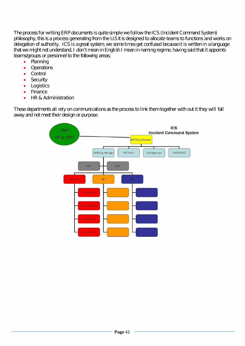
7/28/2019 Essential Knowledge for Potential Offshore Installation Managers
http://slidepdf.com/reader/full/essential-knowledge-for-potential-offshore-installation-managers 42/101
Page 42
The process for writing ERP documents is quite simple we follow the ICS (Incident Command System)philosophy, this is a process generating from the U.S it is designed to allocate teams to functions and works ondelegation of authority. ICS is a great system, we some times get confused because it is written in a languagethat we might not understand, I don’t mean in English I mean in naming regime, having said that it appointsteams/groups or personnel to the following areas;
Planning Operations Control Security Logistics Finance HR & Administration
These departments all rely on communications as the process to link them together with out it they will fallaway and not meet their design or purpose.

7/28/2019 Essential Knowledge for Potential Offshore Installation Managers
http://slidepdf.com/reader/full/essential-knowledge-for-potential-offshore-installation-managers 43/101
Page 43
It is vital that all personnel onboard your facility understands the ERP document and has input into its
functionality, it will be one of the many reference materials that will be used during an accident investigation itis designed to demonstrate how we respond to an emergency and who does what. Make no mistake if we saywe are going to behave in this manner (as stated in the ERP) we better make sure we do on the day, if we playlip service to the document by this I mean train one way but fight another then we will be providing a leveragepoint which will be opened up and inside that cavity will lie what we commonly call blame and that will beissued to someone or something. What I am trying to say here is do what we have written and if what iswritten is not how we do it then rewrite it, and test that it works, this is done during our scheduled drills &exercises, no one dies on a training day. This is how the military have been doing it for years.
I have further simplified the process of Emergency job delegation, understanding & performance into a wheelthat is both easy to use and in line with industry best practices, I have put one together for the offshore
personnel and one for the onshore support team personnel, who fall into the ICS system in the coordination,finance, support, logistics areas, please see following picture.

7/28/2019 Essential Knowledge for Potential Offshore Installation Managers
http://slidepdf.com/reader/full/essential-knowledge-for-potential-offshore-installation-managers 44/101
Page 44
DISTRIBUTED CONTROL SYSTEMS
Understanding the FPSO Mooring system, ballasting and safe operating envelopes.
Not required for Managers of production platforms but very necessary if your facility is a converted drillingrig, not piled directly into the sea bed or a spread moored Floating Production Storage and Offloading vessel.
The above is a diagram of a turret mounted FPSO with a nine anchor, spread moored pattern. The Oil and gasproduction lines and the Water injection and Gas injection lines are laid out in a lazy – S formation with midocean saddles to provide buoyancy and take some weight off the attachments in the bow.In this particular vessel, oil is processed on board and stored in the cargo tanks which run from bow to sternalong the length of the vessel. Ballast water is stored in the tanks that form a double skin between the oilstorage and the sea. Ballast water is taken in and pumped out to maintain the balance of stresses and momentsthroughout the vessels hull. It is quite possible to break a vessel’s back by putting the weight of the cargo in thewrong place. In this vessel the product is off loaded to another vessel over the stern. The crude oil pumps arealso in the stern area and the offloading plan stipulates that there should be a stern deep attitude to the vessel
for offloading. The offloading plan is very important for an FPSO and this plan must be followed rigorously. It is unlikely thatproduction will be shut down in order to off load and it will be important to resolve tank dips.
Understanding of the purpose of control systems and the causes and effects of significant alarm trips.A Distributed Control System (DCS) typically uses custom designed processors as controllers and uses bothproprietary interconnections and communications protocol for communication. Input and output modules formcomponent parts of the DCS. The processor receives information from input modules and sends information tooutput modules. The input modules receive information from input instruments in the process and transmitinstructions to the output instruments in the field. Computer buses or electrical buses connect the processor and
modules through multiplexer or demultiplexers. Buses also connect the distributed controllers with the centralcontroller and finally to the Human Machine Interface (HMI) or control consoles.

7/28/2019 Essential Knowledge for Potential Offshore Installation Managers
http://slidepdf.com/reader/full/essential-knowledge-for-potential-offshore-installation-managers 45/101
Page 45
Elements of a distributed control system may directly connect to physical equipment such as switches, pumpsand valves or may work through an intermediate system such as a SCADA system.
Distributed Control Systems (DCSs) are dedicated systems used to control manufacturing processes that are continuous
or batch‐oriented, such as oil refining, petrochemicals, central station power generation and papermaking. DCSs are
connected to sensors and actuators and use set point control to control the flow of material through the plant. The
most common example is a set point control loop consisting of a pressure sensor, controller, and control valve. Pressure
or flow measurements are transmitted to the controller, usually through the aid of a signal conditioning Input/Output
(I/O) device.
When
the
measured
variable
reaches
a certain
point,
the
controller
instructs
a valve
or
actuation
device
to
open or close until the process reaches the desired set point. Large oil refineries have many thousands of I/O points and
employ very large DCSs. Processes are not limited to flow through pipes, however, and can also include things like paper
machines and their associated variable speed drives and motor control centers and many others.
A typical DCS consists of functionally and/or geographically distributed digital controllers capable of executing from 1 to
256 or more regulatory control loops in one control box. The input/output devices (I/O) can be integral with the
controller or located remotely via a field network. Today’s controllers have extensive computational capabilities and, in
addition to proportional, integral, and derivative (PID) control, can generally perform logic and sequential control.
DCSs may employ one or several workstations and can be configured at the workstation or by an off ‐line personal
computer.
Local
communication
is
handled
by
a
control
network
with
transmission
over
twisted
pair,
coaxial,
or
fiber
optic cable. A server and/or applications processor may be included in the system for extra computational, data
collection, and reporting capability.
There is, in several industries, considerable confusion over the differences between SCADA systems and DCS.Generally speaking, a SCADA system usually refers to a system thatcoordinates, but does notcontrol processes in real time. The discussion on real-time control is muddied somewhat by newer telecommunicationstechnology, enabling reliable, low latency, high speed communications over wide areas. Most differencesbetween SCADA and DCS are culturally determined and can usually be ignored.
The term SCADA usually refers to centralized systems which monitor and control entire sites, or complexes of systems
spread out over large areas (anything between an industrial plant and a country). Most control actions are performed
automatically by Remote Terminal Units ("RTUs") or by programmable logic controllers ("PLCs"). Host control functions
are usually restricted to basic overriding or supervisory level intervention. For example, a PLC may control the flow of
cooling water through part of an industrial process, but the SCADA system may allow operators to change the set points
for the flow and enable alarm conditions, such as loss of flow and high temperature, to be displayed and recorded. The
feedback control loop passes through the RTU or PLC, while the SCADA system monitors the overall performance of the
loop.

7/28/2019 Essential Knowledge for Potential Offshore Installation Managers
http://slidepdf.com/reader/full/essential-knowledge-for-potential-offshore-installation-managers 46/101
Page 46
Data acquisition begins at the RTU or PLC level and includes meter readings and equipment status reports that are
communicated to SCADA as required. Data is then compiled and formatted in such a way that a control room operator
using the HMI can make supervisory decisions to adjust or override normal RTU (PLC) controls. Data may also be fed to
a Historian, often built on a commodity Database Management System, to allow trending and other analytical auditing.
SCADA systems typically implement a distributed database, commonly referred to as a tag database, which contains
data
elements
called
tags
or
points.
A
point
represents
a
single
input
or
output
value
monitored
or
controlled
by
the
system. Points can be either "hard" or "soft". A hard point represents an actual input or output within the system, while
a soft point results from logic and math operations applied to other points. (Most implementations conceptually
remove the distinction by making every property a "soft" point expression, which may, in the simplest case, equal a
single hard point.) Points are normally stored as value‐timestamp pairs: a value and the timestamp when it was
recorded or calculated. A series of value‐timestamp pairs gives the history of that point. It is also common to store
additional metadata with tags, such as the path to a field device or PLC register, design time comments, and alarm
information.
An important part of most SCADA implementations is alarm handling. The system monitors whether certainalarm conditions are satisfied, to determine when an alarm event has occurred. Once an alarm event has beendetected, one or more actions are taken (such as the activation of one or more alarm indicators, and perhaps the
generation of email or text messages so that management or remote SCADA operators are informed). In manycases, a SCADA operator may have to acknowledge the alarm event; this may deactivate some alarmindicators, whereas other indicators remain active until the alarm conditions are cleared. Alarm conditions canbe explicit - for example, an alarm point is a digital status point that has either the value NORMAL or ALARMthat is calculated by a formula based on the values in other analogue and digital points - or implicit: theSCADA system might automatically monitor whether the value in an analogue point lies outside high and lowlimit values associated with that point. Examples of alarm indicators include a siren, a pop-up box on a screen,or a coloured or flashing area on a screen (that might act in a similar way to the "fuel tank empty" light in acar); in each case, the role of the alarm indicator is to draw the operator's attention to the part of the system 'inalarm' so that appropriate action can be taken. In designing SCADA systems, care is needed in coping with acascade of alarm events occurring in a short time, otherwise the underlying cause (which might not be theearliest event detected) may get lost in the noise. Unfortunately, when used as a noun, the word 'alarm' is used

7/28/2019 Essential Knowledge for Potential Offshore Installation Managers
http://slidepdf.com/reader/full/essential-knowledge-for-potential-offshore-installation-managers 47/101
Page 47
rather loosely in the industry; thus, depending on context it might mean an alarm point, an alarm indicator, oran alarm event.
Industrial safety systems are crucial in any hazardous plants such as oil and gas plants. They are used to protect
personnel, the environment, and plant in case the process went beyond the control margins. As the name suggests,
these systems are not intended for controlling the process itself but rather protection. Process control is performed by
means of process control systems (PCS) and is interlocked by the safety systems so that immediate actions are taken
should the process control systems fail.
Process control and safety systems are usually merged under one system, called Integrated Control and Safety System
(ICSS). Industrial safety systems typically use dedicated systems that are SIL 2 certified at minimum; whereas control
systems can start with SIL1. SIL applies to both hardware and software requirements such as cards, processors
redundancy and voting functions.
There are three main types of industrial safety systems:
Process Safety System or Process Shutdown System, (PSS).
Safety Shutdown System (SSS): This includes Emergency Shutdown-(ESD) and EmergencyDepressurization-(EDP) Systems.
Fire and Gas System (FGS).
These systems may also be redefined in terms of ESD/BDV levels as:
ESD level 1: In charge of general plant area shutdown, can activate ESD level 2 if necessary. This levelcan only be activated from main control room in the process industrial plants.
ESD level 2: This level shuts down and isolates individual ESD zones and activates if necessary EDP.
ESD level 3: provides "liquid inventory containment" and is
PSS
The process safety system (sometimes called process shutdown system) must carry out the process shutdown function,
acting on the lowest level of protection. They shall generally act as an additional loop that protects and/or trips
equipment and applicable to the fire zones or the process units.
SSS
The safety shutdown system shall shutdown the facilities to a safe state in case of an emergency situation, thus
protecting personnel, the environment and the asset. Safety Shutdown System shall manage all inputs and outputs
relative to
Emergency
Shut
down
(ESD)
functions
(environment
&
personnel
protection).
This
system
might
also
be
fed
by signals from the main fire and gas system.
FGS
The main objectives of the fire and gas system are to protect personnel, environment, and plant (including equipment
and structures). The FGS shall achieve these objectives by:
Detecting at an early stage, the presence of flammable gas,
Detecting at an early stage, the liquid spill (LPG and LNG),
Detecting incipient fire and the presence of fire,
7/28/2019 Essential Knowledge for Potential Offshore Installation Managers
http://slidepdf.com/reader/full/essential-knowledge-for-potential-offshore-installation-managers 48/101
Page 48
Providing automatic and/or facilities for manual activation of the fire protection system as required,
Initiating signals, both audible and visible as required, to warn of the detected hazards,
Initiating automatic shutdown of equipment and ventilation if 2 out of 2 or 2 out of 3 detectors
Initiating the blow down system.
ESD
Emergency Shutdown‐(ESD) systems are aimed at isolating (closing) any hazardous valves in a process due to abnormal
conditions.
BDV
Due to closing ESD valves in a process there may be some trapped flammable fluids and thus must be released in order
to avoid any undesired consequences (such as pressure increase in vessels and piping). For this reason Blow down‐
(BDV) Systems are used in conjunction with the ESD systems to release (to a safe location and in a safe manner) such
trapped fluids.
PERMIT TO WORK SYSTEM
Thorough knowledge of the PTW system and Risk Assessment procedures.
The Permit to Work system covers the control of all activities relating to, maintenance, hazardous work and non‐routine
activities, which may result in injury to personnel or damage to process equipment, and harm to the environment.
The Permit to Work system is part of an overall HSE Management System. The procedure may be supported by risk
assessments or guidance notes and safety notices. A safe environment can only be achieved through planning, good
communication, training, implementing safeguards, monitoring of the worksite and inspection upon completion of the
work.
The objectives and functions of the PTW system can be summarized as follows:
Systematically assessing the potential hazards in a planned scope of work.
Specifying the isolations and precautions required preventing potential hazards being realized.
Providing an administrative system to clarify responsibilities of personnel involved.
Ensure that all non routine work is coordinated and controlled.
Provide a record to show that a safe system of work has been used and the necessary precautions have been
considered and implemented.
Controlling the interface between different work activities and worksite conditions.
To establish conditions that will enable the requested work to be undertaken in a specific location, at a particular time, without danger to personnel or the facility.
To ensure effective control in case of concurrent conflicting work, this individually may not compromise safe working procedures, but in combination, could create the potential for more serious hazards.
To ensure that all personnel including sub‐contractors and visitors will receive structured training in the use of the PTW system at which time their competency will also be assessed.
To comply with the statutory provisions with regard to work site safety and related matters.

7/28/2019 Essential Knowledge for Potential Offshore Installation Managers
http://slidepdf.com/reader/full/essential-knowledge-for-potential-offshore-installation-managers 49/101
Page 49
As a communication tool between superintendents, supervisors and the workforce to control activities and simultaneous activities.
The Permit to Work system provides a means of systematically assessing the potential hazards involved in a planned
scope of work. The system functions through:
A system of defined levels of responsibility.
Forward planning of the work in cooperation with affected personnel. This must establish the precise task to be accomplished and the sequential completion of the task.
Clear definition of the area and the system/equipment where and upon which the work is to be carried out and any hazards which may arise from such work.
Determining if the work will affect any other area, system or equipment, either adjacent or remote, or conflict
with any other work or safety requirements.
Communications of these plans to those who will do the work and all other personnel who could be affected by the work.
Careful checking and implementation of precautions to be taken, including the safety of equipment and personnel, the provision of protective equipment and extra personnel for safety monitoring.
Controlling and observing safe working practices while the work is being carried out.
Leaving the worksite clean, clear and safe upon completion of the work and ensuring that nothing is left in a condition/state which might endanger any personnel or affect the overall safety and integrity of the
installation.
The system uses a form which, authorizes specific work, in a specified area and lists the precautions required to
ensure safety during the authorized period of time allocated for the work. A Permit to Work is not a transfer
of responsibility for a piece of equipment, plant or area. The issue of a permit by itself does not make a job
safe. Those who are preparing and carrying out the work can only achieve these requirements.
Risk assessment is a structured and systematic process for identifying and analyzing HS&E hazards associatedwith an activity/ operation, developing mitigation and control measures to manage and mitigate the risks to anALARP level. The assessment is important as it shall determine the order of priority based on the level of riskand appropriation of corrective/preventive measures. Risk assessment techniques, ranging from a simple qualitative method of hazard identification to a morecomplex advanced quantitative method shall be employed to highlight how hazards can occur and provide aclear understanding of their nature and possible consequences.In general, the commonly used risk assessment techniques are:
HAZard Identification (HAZID) Study
HAZID (HAZard IDentification) is a high-level, systematic assessment of a facility, system or operationintended to identify potential hazards. This method is often used as a basis for risk assessment.
HAZard and OPerability (HAZOP) Study
HAZOP (HAZard & OPerability) is a well established method for identifying potential safety and operationalproblems associated with the design, maintenance or operation of a system. A HAZOP is a formal andobjective process, where different parts or sections of a given system are assessed with the aid of "Guidewords". This ensures a systematic and well documented evaluation of potential

7/28/2019 Essential Knowledge for Potential Offshore Installation Managers
http://slidepdf.com/reader/full/essential-knowledge-for-potential-offshore-installation-managers 50/101
Page 50
problems/hazards.
J ob Safety Analysis (JSA)
A Job Safety Analysis (JSA) is a method that can be used to identify, analyse and record the steps involved inperforming a specific job, the existing or potential safety and health hazards associated with each step, and therecommended action(s)/procedure(s) that will eliminate or reduce these hazards and the risk of a workplace
injury or illness.
Environmental Impact Assessment (EIA)
An Environmental Impact Assessment (EIA) is an assessment of the likely positive and/or negative influence aproject or operation may have on the environment. The purpose of the assessment is to ensure thatenvironmental impacts are considered before deciding whether to proceed with new projects.
Environmental Risk Assessment (ERA)
The assessment on environmental effects based on data concerning ‘hazards’ and ‘environmental sensitivities’to identify where environmental effects may be encountered and then to evaluate their nature, severity andlikelihood of occurrence.
Health Risk Assessment (HRA)
The identification of health hazards in the workplace and subsequent assessment of risk to health. Theassessment takes into account existing or proposed control measures. Where appropriate, the need for furthermeasures to control exposure is identified.
Chemical Health Risk Assessment (CHRA)
Chemical Health Risk Assessment is a process that combines available information on chemical and exposureto estimate the probability that someone will experience adverse health effects as a result of exposure to thechemical
Other risk assessment techniques may be used if deemed necessary. The use of appropriate methodology shallbe taken into consideration the scope of study and complexity of the activity or operation. A multidisciplinaryteam approach shall be applied to ensure every foreseeable hazard and its associated risks are identified,considered, elaborated and documented.
Risk Assessment Team
The Risk Assessment Team shall consist of multidisciplinary personnel. The team leader shall be led by acompetent person and responsible to assemble team members based on the following criteria:· Sound knowledge of the study scope and methodology;· Expertise;· Availability; and· Discipline represented.
Risk Assessment Process
The risk assessment process shall consist broadly of the following three main steps:· Hazard identification;

7/28/2019 Essential Knowledge for Potential Offshore Installation Managers
http://slidepdf.com/reader/full/essential-knowledge-for-potential-offshore-installation-managers 51/101
Page 51
· Risk evaluation (a function of severity and frequency of occurrence); and· Risk mitigation and control.
Hazard Identification
The objective of this step in the risk assessment process is to identify all possible hazard(s) that can cause harmto people and the environment.
Risk Evaluation
Once hazards/ risks have been identified, they shall then be evaluated as to their potential severity of loss andto the probability of occurrence. This can be achieved via a qualitative or quantitative approach.Depending on the type of risk assessment technique used, qualitative, semi quantitative or quantitativeapproach shall determine the extent of the risk associated with the identified hazards. The use of a semi-quantitative risk assessment shall make reference to anHS&E Risk Assessment Matrixthat requires the team toassign the likelihood of occurrence with existing safeguards based on exposure and probability, and severity of consequences without safeguards.Any risk that is evaluated to fall under Category I and II shall be addressed immediately; a Category III riskshould be addressed while risk that falls under Category IV or V should be monitored.
The use of a Quantitative Risk Assessment shall describe the chance of risk to personnel/ public,environmental and/or economic as a result of exposure to a hazard. The UK Health and Safety Executive’s
Tolerability of risk from nuclear power stations (1992) criteria should be used to set the limit for maximumtolerable risk of a fatal accident to personnel and public as presented below:
Risk to Personnel. Risk to the public.
Risk Mitigation and Control
Results from the risk evaluation shall be used to develop risk mitigation or control alternatives. Mitigationand/or control alternatives should take into account feasibility, risk reduction potential and cost. The preferredhierarchy of measures is to prevent the occurrence of the hazard than to mitigate the consequences caused bythe hazard; and should be addressed using one or more controls in the following hierarchy:· Elimination: controlling the hazard at source;· Substitution: replacing one substance or activity with a less hazardous one;· Isolation/enclosure: separate the hazard from the work area;· Engineering control: modify existing machinery or facility;· Administrative control: develop work methods/procedures and/or provide training to recognize hazards andreduce conditions of risk; and· Personal Protective Equipment: the last option that should be considered to deal with the hazard, where thehazard cannot be removed or reduced by any other means.

7/28/2019 Essential Knowledge for Potential Offshore Installation Managers
http://slidepdf.com/reader/full/essential-knowledge-for-potential-offshore-installation-managers 52/101
Page 52
The cost-benefit analysis (CBA) shall be used for the evaluation of various risk mitigation and controlmeasures, notably for the level of risk within the ALARP region. CBA cannot be regarded as a substitute forengineering judgment, but may assist in the decision making process where potential upgrades or modificationsare under consideration. The table below provides the guidance in assessing potentialDesign changes, modifications and upgrades.
Cost to Avert One Fatality (MYR)
Assessment0 Highly effective always implement5000 Effective, always implement50000 Effective, implement unless risk isNegligible500000 Consider, effective if individual riskLevels are high5000000 Consider at high risk levels or where
There are other benefits50000000 Ineffective
PLL should be utilized to calculate ICAF (Implied Cost of Averting a Fatality), a measure of the costeffectiveness of a potential design change, modification or upgrade and method to demonstrate ALARP. Therelationship between ICAF and PLL is as follows:
ICAF =Cost of modification(Initial PLL – Reduced PLL)A low ICAF for a proposed risk mitigation and control measure implies that it is highly effective, because thecost is low compared to the risk reduction achieved.
Conversely, a high ICAF implies a relatively ineffective risk reduction measure, indicating that perhaps themoney should be diverted to an alternate.
Follow-up and Stewardship The result of the specific risk assessment shall be documented. Personnel assigned and timeframe to implementthe recommended risk mitigation and/or control measures shall also be documented. The initiator of the riskassessment shall develop a tracking mechanism to follow-up on the recommended risk mitigation and/orcontrol measures, ensure closures and report to his superior.An audit should be performed by the HS&E Department to ascertain that all recommended risk mitigationand/or control measures are closed out.
Training

7/28/2019 Essential Knowledge for Potential Offshore Installation Managers
http://slidepdf.com/reader/full/essential-knowledge-for-potential-offshore-installation-managers 53/101
Page 53
Appropriate training shall be provided to personnel involved in risk assessments to ensure that they are capableof identifying and successfully executing risk assessment activities. Appropriate training shall be provided tothe Risk Assessment Team to ensure they are capable of carrying out the risk assessment activities.
PLANNED MAINTENANCE
Knowledge of the Computerized Planned Maintenance and Inspection systems.
The computerized planned maintenance system is the application chosen by the parent company to manage allmaintenance within the company installations. There are several systems in use worldwide. Maximo is one andSAP another. Whichever application is employed it will provide electronic links and interfaces with documentmanagement, the engineering database, finance system, site equipment registers and ex registers.
The Planned Maintenance Routine is a pre defined set of tasks, issued at regular intervals by the maintenancemanagement system (via a Work Order) that details maintenance activities to be executed on a particularsystem, process or piece(s) of equipment.
The PM is an object within the system that generates the PMR. It defines the equipment, process or system tobe maintained by reference to an Operating location (tag), the frequency, priority and schedule of the activity.
The PM record also references the Job Plan (work instruction) to be carried out. The Job Plan is an object within the system that details the specific work to be carried out. The Job Plan holdsa generic detailed work instruction stored within the document management system. This work instruction isprinted with the associated work order.
All PMRs fall within the Permit to Work system. No maintenance can be carried out without the full appraisalof supervision. The intention behind a Planned Maintenance Routine is that all aspects of maintaining

7/28/2019 Essential Knowledge for Potential Offshore Installation Managers
http://slidepdf.com/reader/full/essential-knowledge-for-potential-offshore-installation-managers 54/101
Page 54
performance and usability will be addressed. Safety Critical Elements will receive the same level of scrutiny asmore mundane material. The CMMS also provides a record of actions carried out, materials used and servicehistory. Equipment that is being replaced at each service interval may require a review of the service intervaland vice versa, if no actions are required. The more history that is added into the CMMS the better the systemworks for everyone. Full service carried out. This tells the next person to carry out the work nothing if he has alot of material to replace.Supervision must sign off on CMMS work. They also may have to comply with prioritized work schedules.
Safety Equipment always has a high priority. It is usually a function of continued operation that certain safetycritical equipment is never omitted from regular maintenance.
It may be found that the CMMS planned maintenance routines do not meet installation requirements. This mayhappen when vendor suggestions are included into CMMs without a formal review. A procedure can be used toovercome this problem. Engineering changes, if agreed by management and supervision are used to adjustCMMS requirements.
PRODUCTION & PROCESS Thorough understanding of procedures including emergency procedures and the use of telemetry system.
Operating, Maintenance and Management Procedures are the written means whereby equipment and systemsare set up, maintained and safely operated according to vendor manuals, best practice and agreed principles.
These procedures may be written by the operators who are going to use them or professional writers who havebeen given an exact brief. Whatever the source of the procedures they need to be accurate, safe and meet theapproval of management. The OIM as the senior manager of the installation accepts the procedures on behalf of and for the benefit of the installation.A library of all the relevant material pertinent to the installation shall be maintained on the facility. Thismaterial shall be the most up to date available and contain all the plant specific information that is available.All of this material shall be reviewed and updated on a regular basis. This material shall form the installationaccessible controlled documentation. The OIM shall accept new procedures, on behalf of the installation,
ensure that the library is updated, disseminate the new information throughout the workforce and ensure thatprevious examples are removed from circulation. He shall ensure that reviewed and updated material for theprocedures is accurate, meets requirements and is in compliance with relevant regulations and legislation. Heshall forward any installation derived procedures to onshore management for approval and document control.
Understanding of Production Operations. The offshore installation is a small self contained town but it is still essentially an oil exploitation facility. Asthe senior manager of this oil exploitation facility the OIM should have an understanding of the principles thatmake the facility work.
Separation. The term Oil and Gas Separator in petroleum production terminology, refers to a pressure vessel which isdesigned to separate reservoir fluids into liquid and gaseous components. Any process which is designed toseparate substances relies on the fact that the substances are different from each other in some way. The fluidsmust not be the same mass per unit volume, that is: They must have different densities.Oil and Gas Separators depend on a force to take advantage of the differences in Densities between thecomponents by separating them. The force we depend on to separate the fluids is Gravity. Since a separatordepends upon gravity to separate the fluids, the ease with which two fluids can be segregated depends upon
their Relative densities. The greater the difference in the density of each of the components to be separated themore readily they will separate.

7/28/2019 Essential Knowledge for Potential Offshore Installation Managers
http://slidepdf.com/reader/full/essential-knowledge-for-potential-offshore-installation-managers 55/101
Page 55
That is the theory, the more time that is available; the more complete will be the separation. Reservoir fluids, amixture of oil, gas and water, under pressure will separate if allowed to stand still long enough. However this isnot the way that it is done in our industry. We need to produce separated fluids out with the bounds of naturalseparation. By listing a set of objectives for a separator, we will have a better understanding of what functionswe want the separator to perform. There are Four Separator objectives listed as follows: Cause a primary phase separation of the liquid hydrocarbons from those which are mostly gas. Refine the primary separation by means of a secondary phase separation which removes the entrained
liquid mist from the gas. Further refine the separation by removing the entrained gas from the liquid. Discharge the separated gas and liquid from the vessel under steady, controlled conditions and ensure that no re‐
entrainment of one phase into the other can occur, in other words stabilise the crude oil.
Of course whilst these objectives are stated as separator objectives it may be necessary to use more than oneseparator to achieve complete separation of the fluids into the gas, oil and water components. To achieve theseobjectives a separator must be designed to: Control and disperse the energy of the feedstock. Ensure that the gas and liquid flow rates are low enough so that gravity segregation and an approach to
vapour-liquid equilibrium can occur.
Control the accumulation of froth’s and foams in the vessel. The size of the droplets. The Density of the liquid droplet compared to the density of the gas. The velocity at which the gas stream is travelling through the separator. The Turbulence which exists in the flowing gas stream.
Of these factors:
The difference in density between oil and gas and the droplet size will be determined by the composition of the well stream.
The Velocity of the gas stream is determined by the size of the separator and its throughput.
Fluid flow is the result of a pressure gradient, consequently when well fluid flows through the formation,tubing, chokes, reducing regulators and surface lines; there is a falling pressure gradient in the downstreamdirection. At some point on the flow path the pressure reduction is sufficient to initiate the escape of gas fromthe liquid. This free gas flows through the system in contact with the liquid (in which the remaining gas is stilldissolved). This process is known as flash separation.As the reservoir fluids enter the vessel an initial separation of gas and liquid takes place. This happens becauseof: A reduction in Velocity.
A reduction in Pressure.
A Change in Flow Direction.
The Velocity of the inlet stream is reduced as the fluids flow from a relatively small diameter pipeline into thelarge volume of the separator. The Pressure is reduced by maintaining a controlled pressure on the vessel lowerthan that of the inlet stream. The change in flow direction is accomplished by placing some form of deflector/baffle at the inlet to the separator.
The secondary separation of liquid droplets from the gas by gravity settling will not usually remove very smallparticles. These particles tend to remain in the gas stream in the form of mist. In order that the gas leaving aseparator is as free as possible from liquid, a final Mist Extraction section is built into the vessel. Mistextraction is accomplished using either an impingement or a centrifugal force mechanism. The most commonmist extraction device is the knitted wire mesh pad which is an impingement mechanism.
You will remember that a 3 phase separation process not only removes gas from liquid, as we have just seen,but also separates oil & water. This, in effect, adds a fifth part to the total process within the separator. Oil and
water do not mix. If theses liquids are left long enough in a vessel, separation will occur and the oil will floaton top of the water. Oil & Water will separate faster than gas will be liberated from the oil. So, if the Separator

7/28/2019 Essential Knowledge for Potential Offshore Installation Managers
http://slidepdf.com/reader/full/essential-knowledge-for-potential-offshore-installation-managers 56/101
Page 56
is large enough to allow efficient gas separation, then the retention time required for oil and water separationwill be exceeded.Example:
Liquid Residence Time In Separators Separator Size: Diameter =2 m
Length=11m
Volume = (R2
L)=(
2
2 2x 11) =34.6m3
Add 10% for volume of Heads 3.5m3 Total Volume 38.1m3 Liquid volume at 1/2 full: 18,05m3 Maximum Oil Flow Rate: 530 m3/hr or 8.8m3/min
Oil Residence Time =8.8
05.18=2 min
In most cases this is sufficient time for both gas and water to be separated.Wellhead fluid from the HP and MP manifolds are routed to the HP separator A or B where gas, condensateand any produced water are gravity separated. To reduce the incoming liquid momentum, a diffuser is installedat the inlet nozzle of the separator. The inlet diffuser has directional vanes to control and direct the incomingliquids into the catchments baffle below the inlet. The liquid is directed into an area for gravity separation of the oil and water. This section at the base of the separator is baffled which reduces fluid velocity. The liquidsalso pass through a restriction orifice which is used to control slug flow should it occur. The baffles are verticalplates which extend above the normal level of the liquid and are arranged to force the liquid stream into an Spath improving separation and water phase removal. The water is routed to the HP produced water hydrocyclone for subsequent cleanup and disposal. The hydrocarbons flow over a weir into a hydrocarboncompartment where the liquid outlet is located. A 2in vent line passes through the catchments baffle allowingany released gas to pass up into the top section of the separator.Horizontal separators are almost always used for: High Gas/Oil ratio well streams. For foaming well streams. Liquid-from-liquid separators.Horizontal separators are: Easier to skid mount.
Easier to service. Easier to hook up.

7/28/2019 Essential Knowledge for Potential Offshore Installation Managers
http://slidepdf.com/reader/full/essential-knowledge-for-potential-offshore-installation-managers 57/101
Page 57
The horizontal gas flow does not oppose the settling of liquid particles as it does in a vertical separator.
There are circumstances, however, where space constraints may rule out the use of horizontal separators. InHorizontal separators, Gas flow does not interfere with downward flow of liquid drops.
Having developed objectives for oil, water & gas separation, discussed the Ideal separator situation anddecided what the criteria for the quality of the phases are to be, it follows that:
A single, high pressure separator of practical and economic size cannot be expected to produce dry gas. Sales quality oil. Produced water which is of a quality suitable for dumping without further treatment.
7/28/2019 Essential Knowledge for Potential Offshore Installation Managers
http://slidepdf.com/reader/full/essential-knowledge-for-potential-offshore-installation-managers 58/101
Page 58
Control of Separators
Pressure and liquid level are features of the process which can vary. Each can increase or decrease withvariations in separator throughput. In order to obtain optimum separation, the pressure and liquid level must bemaintained at a constant value.Separators have two major controls: Liquid level control Pressure controlLet us consider the basic fundamentals of process control. In any continuous process there are a number of factors which must be kept within certain limits.
These are called theprocess variables The four most common are: Liquid Level Pressure Temperature Fluid Flow
The basic method of achieving control applies to all four
The Control Loop
There are four main elements in a typical control loop: The Process variable The Measuring unit The Controller The Correcting Unit

7/28/2019 Essential Knowledge for Potential Offshore Installation Managers
http://slidepdf.com/reader/full/essential-knowledge-for-potential-offshore-installation-managers 59/101
Page 59
The Process Variable
This is that part of the process which has to be controlled within certain limits (i.e. separator Level and Pressure). The
actual value of the process variable which the operator wishes to maintain is called the desired value. This value is
commonly called the set point.
The Measuring Unit
This unit measures the actual value of the variable. The measuring unit obtains the measured value, i.e. theactual level or pressure in the separator.
The Controller
It is the job of the controller to compare the measured value of the process variable with the desired value. If
the controller senses a deviation between the two it then sends a correcting signal to the final element in thecontrol loop, the correcting unit.For example, suppose you wanted to maintain the separator at 250psi, but the pressure had increased to 275psi.
The desired value is 250psi and the measured value is 275psi. The controller would sense this deviation and instruct the unit to send the appropriate correcting signal. Thecontroller may be operated using air (pneumatic operation) liquid (hydraulic operation) or electronics.
The Correcting Unit
This part of the control loop is usually a valve. On receipt of a signal from the controller it opens or closes toalter the process variable. The measured value is then returned to the one indicated by the desired value. This
valve is commonly known as the level control valve.

7/28/2019 Essential Knowledge for Potential Offshore Installation Managers
http://slidepdf.com/reader/full/essential-knowledge-for-potential-offshore-installation-managers 60/101
Page 60
Separator Level Control
Basically each separator has a level control system as previously described which regulates the position of acontrol valve (LCV) in the oil outlet line. The oil outlet line leads the oil to the next link in the process train.
This could be a lower stage of separation, storage or transfer pumps.If the level in the separator falls the controller closes the control valve to raise the level. If the level in theseparator rises the controller opens the control valve to lower the level via the liquid outlet.
The controller displacer (float) is housed in a stilling well. The stilling well is normally a slotted pipe with the
displacer fitted internally. The purpose of the stilling well is to reduce the turbulence across the displacer.In a 3 phase separator the water/oil interface is controlled by an interface level controller. This controlleroperates over a small range. Detecting the interface and controls it by adjustment of a control valve in thewater drain line. Liquid turbulence, emulsions and silt can affect the accuracy of interface control.Liquid Level Control is required to maintain a constant level to allow time for gravity separation and to preventliquid carry over through the gas outlet to downstream equipment.
To help maintain pressure in a 3 phase separator, prevent oil flow through the water outlet or vice versa. Toensure optimum retention or residence time in most cases the optimum operating level in the vessel would beapproximately 50%.
Pressure Control
As with level control, the basis of a pressure control loop is the same. The controller and the control valvework in the same way as the units used in level control. However, the measuring unit is obviously going to bedifferent as pressure is being measured instead of liquid.Separator pressure is controlled to maintain optimum separation conditions and to provide the necessarypressure to discharge the liquid to the next separation stage. A constant pressure is maintained by means of acontroller which regulates a control valve (PCV) in the gas outlet line.When gas recompression and treating facilities are in operation the gas from the various stages of separationflows directly to them. The separator pressure being controlled by the back pressure in the downstream gasplant.In this mode of operation the pressure indicating controller (PIC) on each separator shall be set slightly above
the back pressure the gas plant is holding on them. If the gas plant shuts down or throughput decreases theseparator pressure increases. When the pressure reaches the set point, the separator controller (PIC) opens thepressure control valve (PCV) to vent the excess gas to flare.
Separator Safety Systems
We have looked at the control of the two main process variables in a separator i.e. Level and Pressure. Thesetwo control systems normally operate with relatively few problems; however there is always the possibility thatfor some reason they fail to maintain control.
This may happen, for example because of instrument malfunction. If this should occur a potentially hazardoussituation will arise.
These are some of the possible malfunctions in a 3 phase separator.
Oil level goes to high Oil level goes to low Pressure continues to increase Pressure continues to decrease Water level goes to high Water level goes to low
If the oil level goes too high, oil could get carried over with gas, causing problems downstream. If the oil levelgoes too low, there is a danger of the gas leaving the separator through the oil outlet.If the pressure increases too much, there is the risk of exceeding the safe working pressure of the separator. In
the situation where the pressure falls too much, there will be insufficient pressure to push the liquids from theseparator.

7/28/2019 Essential Knowledge for Potential Offshore Installation Managers
http://slidepdf.com/reader/full/essential-knowledge-for-potential-offshore-installation-managers 61/101
Page 61
If the water level rises above the internal weir, water will contaminate the oil leaving the separator. Should thewater level go to low, oil will flow from the separator through the water outlet.
To prevent such hazardous situations arising separators have the following protection facilities installed: low level alarm low level shutdown high level alarm high level shutdown
high pressure alarm high pressure shutdown high pressure relief valves
Where crude cooling is required prior to final stage separation, the following protection devices may also befitted: high temperature alarm high temperature shutdown
Regardless of what process variable is being monitored, the alarm and shutdown sequence remains the same. The first up is the alarm allowing the operator to take corrective action. If no corrective action is taken or theaction is ineffective further deterioration occurs and shutdown results.

7/28/2019 Essential Knowledge for Potential Offshore Installation Managers
http://slidepdf.com/reader/full/essential-knowledge-for-potential-offshore-installation-managers 62/101
Page 62
Level Control Safety Systems
What would be the sequence of events if the oil level continued to rise? Remember from the previous sectionthat an increase in level will cause the level control valve to open.
This is a simple illustration of a level control loop. LC 01 is the level controller and LCV 01 is the level controlvalve. In this case an increase in level causes LC 01 to open LCV 01. However, the level may continue to riseand approach a hazardous situation.In order that the operator can be warned of the situation alarm signals are generated by the controller. On theillustration you will see LAH 01 connected to the controller LC 01. LAH stands for Level Alarm High.If the level reaches the setting of LAH 01 an audio/visual alarm would be generated. This alarm would beactuated locally in the vicinity of the process equipment and at the central control room which is normallymanned.If a falling level is the problem a similar alarm is generated by LAL 01. If the situation is not rectified and thelevel continues to rise or fall, then the separator must be protected by automatic shutdown systems.
This final degree of protection uses float operated level switches. These switches will actuate Emergency
Shutdown Valves (ESDV). These switches are mounted on the separator independent of the level controller.
These switches are designated as follows:
LSHH:‐ LEVEL SWITCH HIGH HIGH
LSLL :‐ LEVEL SWITCH LOW LOW
If the level reaches the setting of either of these switches, a signal is sent to the ESD system whichautomatically isolates the vessel by closing the appropriate ESD valve.
Pressure Control Safety Systems
An increase or decrease is potentially hazardous. There are several degrees of pressure protection on aseparator.PC 01 is the pressure controller and PCV 01 is the pressure control valve. If the pressure in the separatorincreases or decreases, PC 01 sends a signal to PCV 01 instructing it to open or close as required.In addition PC 01 activates alarms PAH 01 and PAL 01 if the pressure is too high or too low:
PAH:- PRESSURE ALARM HIGH PAL:- PRESSURE ALARM LOW
There are separate pressure switches mounted externally on the vessel shell; these switches would probably bedesignated as PSHH 01 and PSLL 01
They would be connected to the ESDV system:
PSHH:- Pressure Switch Low Low PSLL:- Pressure Switch Low LowIf either of these switches were activated, the separator would shutdown, be isolated and made safe by closureof the ESD valves.

7/28/2019 Essential Knowledge for Potential Offshore Installation Managers
http://slidepdf.com/reader/full/essential-knowledge-for-potential-offshore-installation-managers 63/101
Page 63
SEPARATOR PROBLEMS.
EmulsionsA common problem is that caused by the water and oil forming an emulsion. This is a mixture of twoimmiscible liquids. Where one of the liquids is dispersed throughout the other in the form of small droplets. Inhydrocarbons the dispersed liquid is usually water.
Emulsion are categorised as “tight” or “loose” (often referred to as “stable” or “unstable”). The type willdepend on the nature of the oil and the amount of water present.Loose emulsions are the more usual type encountered in hydrocarbons.
They are easier to break down. The dispersed droplets are usually large enough for gravity separation to takeeffect quickly as long as no turbulence is encountered.It is more difficult to break down “tight” emulsions because the dispersed droplets are smaller. It takes a longtime to break tight emulsions effectively by gravity separation.Low gravity and high viscosity crude oil tend to form “tight” emulsions. In some emulsion situations, theseparator internal mechanical devices alone will not separate the liquids. Various methods can be used toenhance the separation of the fluids.

7/28/2019 Essential Knowledge for Potential Offshore Installation Managers
http://slidepdf.com/reader/full/essential-knowledge-for-potential-offshore-installation-managers 64/101
Page 64
Heavy crude streams may be heated to reduce the viscosity of the mixture, thereby allowing the coalescers toseparate the fluids. In extreme cases it is necessary to use electrostatic grids or chemical treatment. Chemicaltreatment involves the injection of chemicals into the well fluids just prior to separation.
This chemical, which is called a demulsifier assists in breaking down the emulsion and allows the separator todo its job. Emulsion is one of the main problems of three phase control is that it makes interface level controldifficult.
The interface is not a clear division of oil and water, but an emulsion of the two. The displacer of the water
level controller often intersects the oil/water interface. The displacer may become totally immersed inemulsion.Consequently the level control action will be erratic.
Foaming
Separator capacities may be greatly reduced and the proper functioning hampered due to “foaming” of thecrude. Foaming occurs when the oil fails to release the gas quickly enough as it passes through the vessel,causing gassing within the body of the liquid. This causes a layer of oily bubbles to form on top of the liquidsurface.
The displacer of a level controller is designed to match the specific gravity of the oil in which it operates. Itcannot float in foam.
Therefore with this significant change in specific gravity the level control device will react erratically or willnot function at all. When the displacer sinks a false low level is indicated and the oil outlet LCV will close.
This can result in a carryover of liquids in the gas stream.Foam has an extremely low apparent density and therefore occupies more than its appropriate share of spaceinside the vessel. When the foam blanket is uncontrolled, it may become nearly impossible to remove separatedgas or degassed oil from the vessel without entraining some of the foam material in the liquid or gas removed.Foams, so far as this problem is concerned, fall into two broad categories: surface type foam and body typefoam.
The surface foam, the more common and more readily understood type, is created when change of pressure or
temperature results in a liquid phase material changing, in part, to gas within the body of the liquid. Resultingbubbles quickly rise to the surface. Under normal conditions they break through the surface in company with afine spray of liquids and finally leave as gas phase material; however, when, as a result of emulsifying orsurface active agents, the nature of the liquid prevents the clean liberation of the gas bubbles through thesurface, surface foam results.Body foam is a more complex type of structure restricted generally to the low gravity and high viscositymaterial. Here again, conditions supporting gas liberation within the body of the liquid would normally resultin bubbles which would quickly make their way to the surface, dissipate, and separate. Due, however, to thepresence of certain emulsifying agents within the liquid, or the surface active characteristic of the liquid incompany with its viscosity and gravity characteristics, the gas forms and remains in relatively stable sphericaltraps within the liquid. Many of these do not make their way to the surface because of the interference of other
like globules with which they join and remain relatively stable within the liquid body. As noted, they areprevented from readily reaching the surface as a result of the viscosity or low gravity of the liquid untileventually the entire gas-liquid mass becomes essentially one biphasic body.
There is no line of strict demarcation between surface type and body type foams as defined here but, generallyspeaking, when there is an essentially determinable gas-foam line above the biphasic material and a true liquidbelow, the foam involved is surface foam.Internal mechanical devices for combating foam are not recommended. They are considered to be ineffective.
They can even be counterproductive by offering surfaces which stabilise the foam. The foaming problem is usually overcome by the injection of a defoaming agent upstream of the separator. Themost commonly used defoaming agent is silicone.
Chemical defoamers either prevent the generation of foam by de-activating the surface active components, orbreak the foam already formed by altering the surface tension of the oil film surrounding the gas bubbles.

7/28/2019 Essential Knowledge for Potential Offshore Installation Managers
http://slidepdf.com/reader/full/essential-knowledge-for-potential-offshore-installation-managers 65/101
Page 65
Chemical treatment is the most effective method of combating the problem of foam but the cost is rather high.Equally good results can sometimes be achieved by heating the crude. This is well worth considering in thedesign phase.Slugging Slugging occurs when there is an intermittent, rather than a constant flow of well fluids into the separator. Insome instances the flow may cease altogether for a very short time and then a slug will arrive. This is more
likely to occur in mature oil fields.If the liquid enters the separator in slugs this can cause rapid fluctuations in levels and pressures. The controlsystems could become unstable in attempting to control this situation. In severe cases this could cause ashutdown. Take for example the level control system. If the control system does not react fast enough to allowthe liquid to drain down. When the next slug arrives there could be a loss of level control. This situation couldcause a high level in the vessel, possibly resulting in a high high level shutdown of the separator. This can beovercome by lowering the level set point on the controller. By lowering the operating level, the volume of thevessel is increased within the operating band. Thereby allowing time for the control system to react when aslug arrives. Lowering of the level controller proportional band will speed up the response of the level controlsystem.In some case it may be advantageous to install a valve positioner on the level control valve. This effectivelyallows the level control valve to open more rapidly.
The above solutions could also be tried if difficulties where encountered with pressure control. However, itmust be emphasised that any adjustments to the operating parameters must be carried out in small steps.After each small adjustment the parameters in the separator must be observed over a reasonable period of timebefore proceeding with further adjustments.
Liquid Level
The importance of maintaining the correct liquid level cannot be over-emphasized. Should the level be too low,the retention time will be insufficient. This could prevent complete break-out of gas bubbles in the liquid totake place.
Should the level be too high, the volume of the vapour disengaging space may be reduced below that necessaryto ensure adequate settling of liquid droplets in the gas stream?
Carry‐Over of Liquids in the Gas Stream
A separator and its internal components are designed or selected to suit the condition under which they will beworking. A significant departure from design value of any of the operating conditions is therefore likely toreduce the effectiveness of the separation process. Excessively high inlet gas flow rates are likely to impairseparator efficiency.
For example by re-entrainment of liquid droplets in the gas, the gas flow rate should be checked. If too highreduce to the design value.
A separator component (particularly a mist extractor) may become plugged with dirt, wax or hydrates. If possible check the pressure drop across the component at design flow rate.A pressure drop higher than 0.2 bar indicates plugging. The plugging may be severe enough to produce apressure differential across the component that it can collapse or tear it from its mountings.In this case the component is bypassed and the pressure drop will be zero.
The temperature and pressure should also be checked to determine if hydrate formation is possible. The space above the liquid surface should be sufficient to allow liquid droplets to settle out. If the liquid levelis too high this space is reduced. Adjustments should be made to the level control system to ensure liquid levelis operated at design parameters.

7/28/2019 Essential Knowledge for Potential Offshore Installation Managers
http://slidepdf.com/reader/full/essential-knowledge-for-potential-offshore-installation-managers 66/101
Page 66
Solids
Solid particles such as sand in the well fluids can cause erosion of equipment, blockages to control valves anddamage to rotating equipment.Gas/solid separation can be carried out in gravity settlers, cyclones and impingement devices. However whenthe quantity of dust in the gas is small, filtration is the most common method.
The filter may be a woven bag, witches hat, through which the gas flows or a removable cartridge containing afilter element. Filters should not be used where paraffin's are present.
Liquid/solid separation can be carried out using similar methods as used for gas. However, in order to dealwith a well stream containing an appreciable amount of sand a separator may be fitted with a sand cone andwater jets (e.g. Sparge pipes). The water jets wash the sand down into the cone into a drain from which it canbe removed. In cases of high sand production a vessel may be taken out of service for internal cleaning.
GAS COMPRESSION. The Separation process is often called the heart of the process. If that is the case then Compression is the lungsof the process.
The process equipment referred to as The Compressor is designed to increase gas pressure. The need for gas atincreased pressure is usually to fulfil one or more of the following criteria:
i) gas export via pipeline,ii) Injection into the reservoir for pressure maintenance,iii) use in wells for artificial lift (gaslift),iv) liquid product recovery,
v) Fuel gas.
In order to increase pressure of gas to the appropriate level required to carry out the above processes a numberof different methods may be utilized. However the vast majority of compressors used for production operationsin the oil industry are:Reciprocating Type Compressors. This category of compressor operates on a positive displacement
principle using a piston within a cylinder. They operate at relatively low speeds compared to the centrifugaltype.Centrifugal Type Compressors. This category of compressor utilises the effects of centrifugal force toincrease gas pressure and operates at high speed. It has far less moving parts than the reciprocating type of compressor.Other types of compressor include axial flow and positive displacement type screw, lobe vane and slide vaneunits.Gas from the separation process is used within the gas compression process for the above purposes. Howeverthe way that that gas is used depends on a variety of variables which are: Reservoir pressure
Ratios of oil and gas volumes produced (the field Gas Oil Ratio – G.O.R). Pressure requirements of platform gas facilities.
In order to recombine the gas from each stage for further use, the pressure of the gas leaving the 2nd stage of separation must be increased to the pressure of the 1ststage.

7/28/2019 Essential Knowledge for Potential Offshore Installation Managers
http://slidepdf.com/reader/full/essential-knowledge-for-potential-offshore-installation-managers 67/101
Page 67
After compression from 2nd to 1st stage separator pressures, all the gas is now at a pressure of 250 psi.However, in our example, the gas requires drying (dehydrating) and will have some of its constituents liquefiedin a gas liquids recovery plant. This requires the gas to be at an even higher pressure. A further stage of compression is therefore required at this point. In our process plant the pressure is raised from 250 psi to 1000
psi for drying and liquids recovery.

7/28/2019 Essential Knowledge for Potential Offshore Installation Managers
http://slidepdf.com/reader/full/essential-knowledge-for-potential-offshore-installation-managers 68/101
Page 68
The residual gas, after dehydration and gas liquids recovery, may be used for three things: Gas lift
Gas Export
Gas re-injection into the Reservoir
In order to export the gas from the offshore location to a terminal onshore a much higher pressure is nowrequired at the platform. Similarly, extra pressure is needed to inject the gas into the well for gas lift. At thispoint in our example, therefore the pressure is raised to 2500 psi by further compression.
Even at this high pressure, we may not be able to re‐inject the gas into the reservoir. The actual pressure required to do this depends on a number of factors such as:
Reservoir depth Reservoir pressure Type of reservoir rockIf more than 2500psi is required then probably another stage of compression would be required.
The above example considers the gas flow on an oil production platform. Gas, which is produced from areservoir, may not be associated with oil. It may be purely a gas field.In the early days of production from a typical gas field, the pressure of the gas at the surface will be sufficient totransport it by pipeline. As the life of the field progresses the natural pressure of the reservoir declines. A pointis reached where this pressure is no longer sufficient to transport the gas.
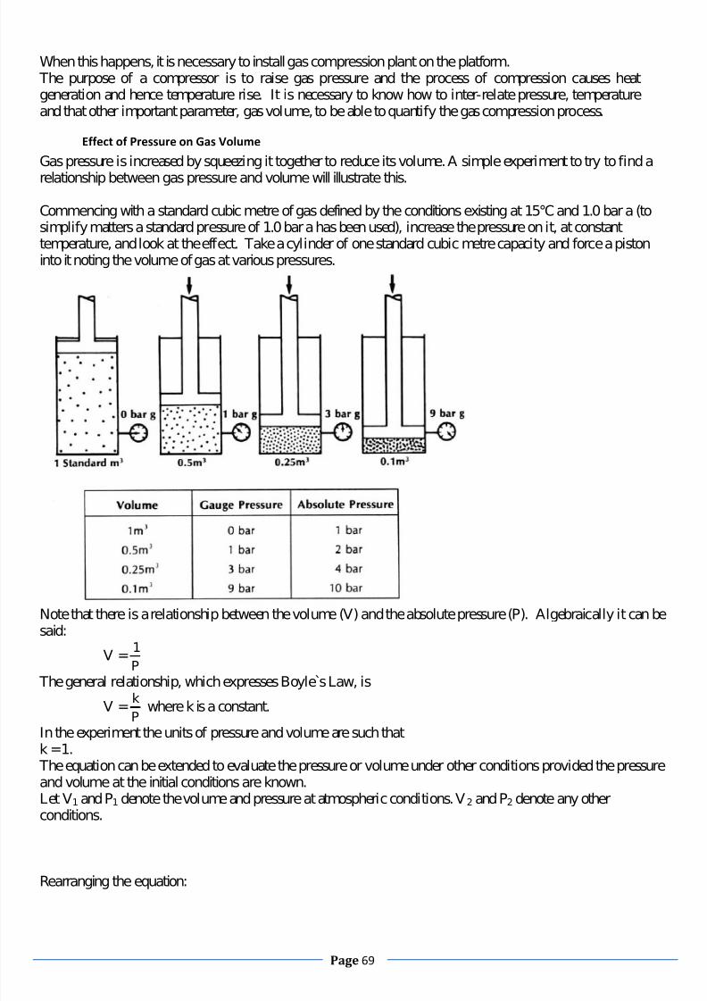
7/28/2019 Essential Knowledge for Potential Offshore Installation Managers
http://slidepdf.com/reader/full/essential-knowledge-for-potential-offshore-installation-managers 69/101
Page 69
When this happens, it is necessary to install gas compression plant on the platform. The purpose of a compressor is to raise gas pressure and the process of compression causes heatgeneration and hence temperature rise. It is necessary to know how to inter-relate pressure, temperatureand that other important parameter, gas volume, to be able to quantify the gas compression process.
Effect of Pressure on Gas Volume
Gas pressure is increased by squeezing it together to reduce its volume. A simple experiment to try to find a
relationship between gas pressure and volume will illustrate this.
Commencing with a standard cubic metre of gas defined by the conditions existing at 15°C and 1.0 bar a (tosimplify matters a standard pressure of 1.0 bar a has been used), increase the pressure on it, at constanttemperature, and look at the effect. Take a cylinder of one standard cubic metre capacity and force a pistoninto it noting the volume of gas at various pressures.
Note that there is a relationship between the volume (V) and the absolute pressure (P). Algebraically it can besaid:
V =P
1
The general relationship, which expresses Boyle s Law, is
V =Pk where k is a constant.
In the experiment the units of pressure and volume are such thatk =1.
The equation can be extended to evaluate the pressure or volume under other conditions provided the pressureand volume at the initial conditions are known.Let V1 and P1 denote the volume and pressure at atmospheric conditions. V2 and P2 denote any otherconditions.
Rearranging the equation:

7/28/2019 Essential Knowledge for Potential Offshore Installation Managers
http://slidepdf.com/reader/full/essential-knowledge-for-potential-offshore-installation-managers 70/101
Page 70
V1 =1P
k
P1V1 =kAnd
P2V2 =k Therefore
P1V1 =P2V2 And
V2 =2
11
P
VP
Apply the formula to the following example:What will be the volume of gas in the cylinder if the pressure is raised to 15 bar g?Use the formula
V2 =2
11
P
VP
WhereP1 =1 bar aV1 =1 m3 P2 =16 bar a(15 bar g +1)
Therefore
V2 =16
1x1=0.062 5m3
Conversely if there is a measured volume in the cylinder the pressure can be determined.It has been assumed so far that the temperature remained constant when conditions of pressure and volumechanged. A change in volume or pressure also causes the temperature to vary. To conduct the previousexperiment it would have been necessary to allow the temperature to stabilise each time the volume waschanged before reading the pressure.
Effect of Temperature on Pressure
The effect of increasing the gas temperature is to increase the pressure. In this experiment there is an enclosedconstant volume and the pressure in the system, as measured by the gauge, varies as heat is applied. Thetemperature rise can be monitored by the installed thermometer.

7/28/2019 Essential Knowledge for Potential Offshore Installation Managers
http://slidepdf.com/reader/full/essential-knowledge-for-potential-offshore-installation-managers 71/101
Page 71
Proceeding further with the experiment would verify the pattern that is beginning to form in the above table i.e.absolute pressure doubles when absolute temperature doubles.In this case taking k' as a constant, and observing that the experiment was conducted with the volumeremaining constant, the relationship can be written
P =k' T where T is theabsolutetemperature
Or k' = T
P
Proceeding in a similar manner to that of the pressure - volume analysis, it is found that
2
2
1
1
T
P
T
P
Effect Of Temperature On Volume The effect of increasing the gas temperature is to increase the volume. If by experiment the enclosure ismaintained at a constant pressure and the volume varies as heat is applied.
Temperature Abs. Temp Volume2170C 500K 1 m37170C 1000K 2 m317170C 2000k 4 m3
The relationship can be written as an equation for calculation purposes:V1 =V2
T1 T2 This relationship is known asCharles' Law.
Ideal Gas Law Combining the equations derived above the following equation appears

7/28/2019 Essential Knowledge for Potential Offshore Installation Managers
http://slidepdf.com/reader/full/essential-knowledge-for-potential-offshore-installation-managers 72/101
Page 72
2
22
1
11
T
VP
T
VP
Which is theIdeal Gas Law? In practice a compressibility factor has to be incorporated in the ideal gas equation to correct for non-idealbehaviour; this factor is a function of pressure and temperature as well as being dependent on the type of gasunder consideration. Accurate calculations, therefore, can only be performed if this information is known.
Pressure, Volume
and
Temperature
It is now clear that a pressure increment is accompanied by an increase in temperature; hence the dischargetemperature of gas from a compressor is greater than the suction temperature.
Adiabatic, Isothermal and Polytrophic Compression Curves An Adiabatic compression involves no heat flow to or from the compression chamber and the final temperaturewill be greater than the initial temperature.An Isothermal compression means that heat must be transferred from the compression chamber as the gas iscompressed so that the temperature remains constant. Such a process would require:i) The compression to be achieved very slowly, and
ii) Low thermal resistance in the chamber wall to allow heat flow into an efficient cooling medium. The normal operating speed and cooling facilities of compressors are such that the compression
cannot be isothermal; in practice, the compression is closer to adiabatic than to isothermal. Such aprocess, being neither isothermal nor adiabatic, is called Polytrophic, and the expression describing it is
PVn =constantwhere 'n' is termed the 'polytrophic exponent'.
The figure below shows compression curves for different values of n, as determined when the process isisothermal, adiabatic, or polytrophic.
For the isothermal process, n =1 and the expression is simply the Boyle’s law relationship PV =constant.When the process is adiabatic
n =
Where
=v
p
C
C

7/28/2019 Essential Knowledge for Potential Offshore Installation Managers
http://slidepdf.com/reader/full/essential-knowledge-for-potential-offshore-installation-managers 73/101
Page 73
Cp and Cv being the specific heat capacity of the gas at constant pressure and the specific heat capacity atconstant volume respectively. The value of depends on the type of gas under consideration, typical valuesbeing 1.4 for air and 1.3 for natural gas depending on its composition.A compression process, for an ideal gas, will be such that 1 <n < since, as previously stated, it will not beisothermal but the value of n will be less than that of by an amount determined by the efficiency of thecompressor cooling system. Most calculations however are based on the adiabatic case with reasonablyaccurate results.
There is another factor which supports use of the adiabatic exponent. The discussion so far is based on theideal gas where is constant. For many real gases varies with the pressure, the tendency being for toincrease as the pressure increases. It is easy to see that such a variation in, and hence n, will cause thecompression curve to be steeper than if n is constant, and has the effect of cancelling the reduction in n due tocooling. In fact, was Cp to increase significantly relative to Cv as the pressure increases, then it would bepossible for n to be greater than the initial value of .
All compressors fall into one of two main groups: Positive displacement/intermittent flow compressors (these are commonly known as positive
displacement compressors).
Continuous Flow Compressors
General A positive displacement compressor works on the principle of pushing a gas from a vessel by partially, orcompletely displacing its internal volume. This is usually achieved by mechanical means.Because the vessel is alternately emptied and refilled the flow is intermittent.The intermittent flow into andout of the compressor causes the pressure to pulsate on both the inlet (suction) and outlet (discharge) sides.Positive displacement compressors will develop sufficient pressure to overcome any resistance to flow and theoperational limits are essentially determined by the driver power and the strength of the compressor parts.Positive displacement compressors fall into two types. They are:
Reciprocating Compressors Rotary Compressors
Reciprocating Compressors
Reciprocating compressors play a very important role in the oil and gas industry. They fall into two types: Piston Type
Diaphragm Type
The action of the fluid-transferring parts is the same in each. A piston or diaphragm is made to pass, or flex,back and forth in a chamber. In the more complex types of compressor, the chamber is equipped with valves on
the inlet and outlet to control the flow of the gas being compressed. The operation of these valves is linked to: The motion of the piston or diaphragm The rise and fall of the pressure in the chamber
Rotary compressors have a variety of uses in the oil and gas industry.In this type, the displacement of the fluid is produced by the rotation of one or more elements within astationary housing. The most common types of rotary compressor found in the oil and gas industry are the:
Screw compressor Lobe compressor

7/28/2019 Essential Knowledge for Potential Offshore Installation Managers
http://slidepdf.com/reader/full/essential-knowledge-for-potential-offshore-installation-managers 74/101
Page 74
Sliding vane compressor Liquid ring compressor
Continuous Flow Compressors
The second group of compressors is the Continuous Flow Compressors. In these compressors themovement imparted to the gas is continuous and constant. Continuous flow compressors fall into two
types: Dynamic Compressors Fluidic Compressors
Dynamic Compressors
Dynamic compressors have a system of elements (called impellers) that are arranged on a shaft. The impellersrotate with the shaft and impart energy of the gas by increasing its velocity. The amount of energy, which isimparted to the gas by a dynamic compressor, is mainly determined by: The design of the impellers The number of impellers used
The speed at which the impellers rotate The density of the gas which is being compressed.
There may be as few as one impeller, or as many as twenty or more impellers, on a shaft. The shaft may berotated at speeds which exceed 30,000 rpm. When the gas leaves each impeller it is allowed to slow down. Asthis happens, kinetic energy is replaced by pressure energyDynamic compressors are classified according to the manner in which the gas flows through the compressor.Within this category are: Centrifugal Compressors – where, in each stage, the gas flows radially outwards. Axial Flow Compressors – here, the gas flows along the line of the shaft.
Mixed Flow
Compressors
–
a combination
of
centrifugal
and
axial
types.
Fluidic Compressors
A variety of compressors are available to perform the task of raising the pressure of a gas. The choice of compressor for a particular application will often be based on two factors:
Compression ratio Capacity
However, many other factors may influence this choice. Some of these are listed below: Nature of gas – hot or corrosive gases may restrict the choice because of the requirement for special
sealing or lubricating systems, or special materials used in construction. Reliability – for continuous running applications
Costs – not only the initial capital costs, but service and maintenance costs may have to beconsidered
Power availability – the power available to drive the compressor could influence the choice of machine.
Of course, compression ratio and capacity are of critical importance when choosing a machine. The followingFigure shows typical pressure and capacity ranges over which various types of compressor usually operate. You should note that the Figure shows very approximate range and some compressors may be capable of
operating outside the ranges indicated.

7/28/2019 Essential Knowledge for Potential Offshore Installation Managers
http://slidepdf.com/reader/full/essential-knowledge-for-potential-offshore-installation-managers 75/101
Page 75
As previously stated separation could be considered the heart of the production process and compressionby the same analogy, the lungs of the process. I would now like to ignore the personification and consider
the Drilling aspect. I am aware that drilling is considered an aspect in itself. However, it has long beenthe case that drilling is very unlikely to be carried out without the intention of production being carriedout thereafter.I would now like to consider aspects of drilling as being carried out on a production facility. For thisconsideration the OIM must take command of all activities on board. What does the OIM need to knowabout Drilling? As usual everything. The Drilling facility for this example is part of the OperatingPlatform. It is not an adjunct, subsea completion, NUI or wellhead platform, it is integral to the facility.At some point in time a production facility which has wellheads attached to the production facility willrequire the attention of a drilling rig. The OIM will find that his area of responsibility is vastly increasedand that drilling is not carried out in anything like the same fashion as normal production. For instance,normal drilling practice is to work with an open hole, something that would suggest “loss of
containment” to an Operations person.Let us not get too close to these technicalities straight away, let us have a look at the equipment that goesto make up a drilling facility.
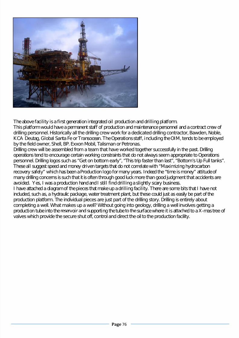
7/28/2019 Essential Knowledge for Potential Offshore Installation Managers
http://slidepdf.com/reader/full/essential-knowledge-for-potential-offshore-installation-managers 76/101
Page 76
The above facility is a first generation integrated oil production and drilling platform. This platform would have a permanent staff of production and maintenance personnel and a contract crew of drilling personnel. Historically all the drilling crew work for a dedicated drilling contractor, Bawden, Noble,KCA Deutag, Global Santa Fe or Transocean. The Operations staff, including the OIM, tends to be employedby the field owner, Shell, BP. Exxon Mobil, Talisman or Petronas.Drilling crew will be assembled from a team that have worked together successfully in the past. Drillingoperations tend to encourage certain working constraints that do not always seem appropriate to Operationspersonnel. Drilling logos such as “Get on bottom early”, “This trip faster than last”, “Bottom’s Up Full tanks”.
These all suggest speed and money driven targets that do not correlate with “Maximizing hydrocarbonrecovery safely” which has been a Production logo for many years. Indeed the “time is money” attitude of
many drilling concerns is such that it is often through good luck more than good judgment that accidents areavoided. Yes, I was a production hand and I still find drilling a slightly scary business.I have attached a diagram of the pieces that make up a drilling facility. There are some bits that I have notincluded, such as, a hydraulic package, water treatment plant, but these could just as easily be part of theproduction platform. The individual pieces are just part of the drilling story. Drilling is entirely aboutcompleting a well. What makes up a well? Without going into geology, drilling a well involves getting aproduction tube into the reservoir and supporting the tube to the surface where it is attached to a X-mas tree of valves which provide the secure shut off, control and direct the oil to the production facility.

7/28/2019 Essential Knowledge for Potential Offshore Installation Managers
http://slidepdf.com/reader/full/essential-knowledge-for-potential-offshore-installation-managers 77/101
Page 77
1. Mud tankWhere the mixture of fluids and chemicals is mixed together to form the mud that will cooland lubricate the drill bit when drilling through rock formations.
2. Shale shakers The screens and vibrating conveyer belt that separates out the returning formation rockfrom the mud returns.
3. Suction line(mud pump)
4. Mud pumpPumps mud down into the well bore to provide weight in the tubing to preventhydrocarbons breaking out, and to cool and lubricate the drill bit.
5. Motoror power sourceElectrical power from marinised diesel motors.
6. Vibrating hose
7. Draw-worksWinch that is attached to the travelling block for raising or lowering the casing string.
8. Standpipe The mud delivery hose attached to the drill rig structure.
9. Kelly hoseFlexible hose connected to the casing.
10. Goose-neck Casing attachment for the Kelly hose.
11. Travelling block Lifting block for running in or pulling out casing.

7/28/2019 Essential Knowledge for Potential Offshore Installation Managers
http://slidepdf.com/reader/full/essential-knowledge-for-potential-offshore-installation-managers 78/101
Page 78
12. Drill lineWinch wire running from the Draw works.
13. Crown block Stationary block at top of drilling derrick.
14. Derrick The structure housing the drilling material.
15. Monkey boardPosition from which the derrick man manipulates the top of lengths of drilling pipe.
16. Stand(of drill pipe) three lengths of drill pipe together make a stand of 90 feet.
17. Pipe rack (floor) Storage space on drill floor for ready use drill pipe.
18. Swivel (On newer rigs this may be replaced by atop drive) Where the non rotating equipment meets therotating equipment.
19. Kelly driveProfiled pipe for attaching tubing.
20. Rotary tableEngine driven chuck for the drill pipe.
21. Drill floor Base plate for the rig, all depths measured from here.
22. Bell nipple
23. Blow-out preventer (BOP) Annular type hydraulically activated ram for protection from annularleakage.
24. Blow-out preventer (BOP) Pipe ram & blind ram hydraulically activated ram for shutting off tubingleakage.
25. Drill stringThe pipe work that is being lowered or retrieved from the well.
26. Drill bit Diamond tipped or tungsten carbide tipped trepanning machine.
27. Casing heador WellheadChristmas tree connections for production tubing tie ins.
28. Flow lineReturn line from the formation to the Shale shaker and mud tanks.
How is the hole drilled?Firstly a large drill bit is used to drill a short interval of hole. This diameter is usually 20” or larger and isknown as conductor pipe. It will be drilled down to about 200’ below the mud level. This is then cased andcemented on the outside to keep the hole from collapsing. This is very much a supporting casing.Next a smaller bit is run inside the first casing. This bit drills out the bottom of the casing and drills a new hole.
This hole may be drilled to about 500’. This new hole is also cased off with 13” casing and cemented in.Again a smaller hole is drilled out and a smaller casing is run to keep the hole from falling in. This casing is 9”
casing and may extend to 1000s of feet. In this way the hole is drilled in stages until the target reservoir rock ispenetrated. At this point the geologists must figure out if there is oil or gas in it. They do this by running logsacross the zone. Logs are run on electric cable, (wire line) which records the physical properties in the rocksuch as, resistively, porosity, density, radioactivity and pore pressure. If the well looks good a final string of 7”casing is run into the production zone and cemented in place. The cement provides a barrier from the formationand the production string.Perforating guns are now run into the hole and perforate the casing across the production zone. This essentiallyallows reservoir fluid to migrate into the well bore and the completion is subject to reservoir pressures andtemperatures unless controlled by mud weight.Production tubing is now run into the hole with a packer to isolate the producing zone from the casing above.Finally the well is produced into a pipeline through the X-mas tree on top of the production tubing and into theproduction facility on surface.
OIM

7/28/2019 Essential Knowledge for Potential Offshore Installation Managers
http://slidepdf.com/reader/full/essential-knowledge-for-potential-offshore-installation-managers 79/101
Page 79
He has the overall responsibility for the safety of the installation and personnel onboard. He will be incommunication at all times with the Senior Supervisors within both the Operations and the Drillingdepartments. All planned Permits to Work will be discussed at meetings where a full complement of Platform Senior Supervision is present. The OIM shall actively participate in the planning of alloperations or delegate overall responsibility for the Well Control operations to the Assistant RigManager if required. He shall however ensure a log of events and WC operations is maintained. TheOIM shall communicate the well control plan forward to the vessel captain, barge engineer, motor man,
and electrician so that they can maintain the rig in proper order while well control operations are on-going.
TOOLPUSHERHe verifies proper on / off tour crew deployment. He shall communicate the status of operations to theRig Manager on a continuous basis. He shall be present on rig floor during the start of well controloperations. Ensure that all equipment is working properly.
DRILLER This guy has ultimate responsibility for kick detection and well shut-in. He will initiate a Kick Log andcontinue logging important well control information and actions taken throughout the well controloperation. He notifies the Assistant Rig Manager that the well is shut-in and assists the OIM /
TOOLPUSHER as directed. Ensures that the space out is correct. He shall supervise the drill crewwhile monitoring the shut-in well. He shall man and operate the pump controls during circulation andwell killing. When circulating out a gas kick, the driller or his designate will monitor the conditions of the mud gas separator (MGS) and adjust circulating rates as warranted.
AD / DERRICKMANHe lines up the mud gas separator, mixing pumps, and degasser as instructed by OIM, TOOLPUSHER,or Driller. He works with the Mud Engineer and ensures proper mud mixing. He checks the Mud GasSeparator for proper alignment and ensures that the rig pumps are operating properly. He shall be in
constant communication with the driller as to volumes, leaks, or any unusual conditions.
FLOORMEN They assist the Driller in shutting in the well and report to their assigned well control station. Whenneeded, they are responsible for stabbing the safety valve and closing under direction of the Driller.
They also monitor the BOP stack; choke manifold and valves for any leaks.

7/28/2019 Essential Knowledge for Potential Offshore Installation Managers
http://slidepdf.com/reader/full/essential-knowledge-for-potential-offshore-installation-managers 80/101
Page 80
OIL SPILL RESPONSE PLANS.
An oil spill response is now a particularly necessary feature of the OIM’s duties. I have sourced a goodexample from the UKCS. This belongs to Talisman and is dedicated to the Piper and Tweedsmuir fields in theCentral North Sea.
This document has been prepared for the Talisman Energy operated Piper, Chanter and Tweedsmuir FieldSystems and sets out the actions that might be taken by personnel working offshore on the Piper platform in the
event of an oil spill to the sea from infield facilities. These procedures are also applicable to personnel onboarddrilling units and vessels engaged in development drilling and well intervention activities within the Piper,Chanter and Tweedsmuir Fields. In the event that onshore support is required to respond to an oil spill, then
Talisman’s Onshore Procedures for Oil Spill Response, which details the roles and responsibilities of Talisman’s Emergency Response Team onshore, would be implemented. These documents have been prepared in accordance with the requirements of the Merchant Shipping (OilPollution Preparedness, Response and Co-operation Convention) Regulations 1998. In addition, the onshoreprocedures meet the requirements of the Offshore Installations (Emergency Pollution Control) Regulations2002. Recommended use of this plan is as follows:
It is stressed that despite the guidance given in this manual, it is the OIM’s priority in the event of a spill totake measures to ensure the safety of personnel and the installation, and to prevent escalation of the incident.
Piper and Chanter Fields

7/28/2019 Essential Knowledge for Potential Offshore Installation Managers
http://slidepdf.com/reader/full/essential-knowledge-for-potential-offshore-installation-managers 81/101
Page 81
Operator Talisman Energy (UK) Limited
North Sea Sector Central North Sea
UKCS Block(s) UKCS Block 15/17a (Piper and Chanter)UKCS Block 21/1 (Tweedsmuir)
Location 58º 28’ N, 0º 22’ E57° 59’ N, 0°11’ E (Tweedsmuir NorthProducer)57° 57’ N, 0° 11’ E (Tweedsmuir SouthProducer)
Field Facilities Fixed production platform with a subseasatellites Chanter and Tweedsmuir.
Approx. Distance to UK coast Approximately 160km from Wick (Piper &Chanter)Approximately 125km from Scottish coast
(Tweedsmuir)Approx. Distance to Median line 75km to UK / Norwegian Median Line (Piper &Chanter)
92km to UK / Norway Median Line(Tweedsmuir)
Water depth 145m (Piper & Chanter)130m (Tweedsmuir)
Function Processes well fluids from Piper, Chanter and Tweedsmuir Fields. In addition it receives oil fromSaltire and also from third parties (ConocoPhillips
MacCulloch Field)
Hydrocarbons produced Crude Oil and NGL’s
Export method 30” Main Oil Line to Flotta Terminal, Orkney
Hydrocarbon inventories Crude Oil (Topsides)366m3 Largest crude oil vessel 110m3 Diesel tanks 430m3 Largest diesel vessel195m3
Flow lines 570m3
Tweedsmuir to Piper 12” flow line 3,460m3 Tweedsmuir South to North 8” flow line 130m3
Infield Oil Spill ResponseFacilities
Equipped for Infield Tier 1 Dispersant SprayingCapability Held on SBV
Supply Base Peterhead
Operations Base Aberdeen

7/28/2019 Essential Knowledge for Potential Offshore Installation Managers
http://slidepdf.com/reader/full/essential-knowledge-for-potential-offshore-installation-managers 82/101
Page 82
Responsible PositionAction Procedures
Platform / Drilling Rig
Alert / Not ify Report spill to Main Control Room immediately. Provide
Location of spill (if know n);
Estimate size of spill;
If ongoing;
Type of oil spill e.g. crude oil, diesel;
Notify OIM.
If spill noticed by third party e.g. surveillance aircraft, assumethat spill has occurred from installation until disproved.
Person observing spil l/Person observing spil l
CR Operator (on duty)/CR Operator (on duty)
Identify Sourceof Spill
Determine source of spill. If leak location cannot be readilyidentified, follow th rough appropriate Oil Spill Checklist
provided in Supporting Information to assist in check. Take appropriate remedial action to stop or control spill.
As required / Asrequired
Confirm spillsize
&
allocate spill
category
Confirm spill size. If necessary a visual estimate may be madeusing the information from the table given in Sec. 4.
Estimate direction of movement of spill using wind direction andtidal data;
Allocate spill into appropriate Tier (refer Spill Size Estimationand Tier Classification in Section 4)
For environmental sensitivity information refers to Sec. 9. For slickmovement data refer to Supporting Information, Section 10.7
As required / OIM / Offshore Rep
OIM / OIM / OffshoreRep
Report Spill Report spill; do not delay reporting if you do not have completeinformation. This can be sent with a follow-up report. However,report as accurately as you can. Use PON1 Proforma
Follow through spi ll reporting requirements in Section 5.
OIM / OIM / OffshoreRep
Obtain Sample
& Photographs A sample of the spilt oil should be taken prior to any dispersant
spraying response. In addition photographs of the incident shouldbe obtained. This may be important for post-incident inquiries.
Procedures for sampling are provided in the Supporting
Information, Section 10.4
OIM / OIM
Spill Response For Tier 1 spills initiate monitoring or chemical dispersionresponse as necessary, request presence of SBV
For Tier 2/ 3 contact Duty Emergency Co-ordinator withoutdelay
Follow through Decision Guide in 7 & Response Options in 8.
OIM / OIM
Incident Log Open & maintain incident log, which should include:
Accurate timing of events;
Reports made and times when reporting has
taken place;
Actions taken;
Contacts made / received.
As di rected by OIM / OIM / Offshore Rep
Incident Stand-
down On closure of incident ensure incident log is collated and sent to
Duty Environment Contact, Talisman House.
Carry out incident investigation and report using usualchannels.
OIM / OIM / OffshoreRep
SPILL SIZE ESTIMATION AND SPILL TIER CLASSIFICATIONIt is important to determine the size of the spill and to classify it. The best estimate of spill size will come fromplant information, for example, the volume of oil in pipe work, vessels, pumping rate and duration, diesel intransfer hose etc. If the spill size cannot be determined from plant information, an estimate of spill size can be
made by observing the size and colour of the slick on the sea surface (see the tables below). Visual inspectioncan be carried out from the installation or standby vessel, but best estimates are made during aerial surveillance

7/28/2019 Essential Knowledge for Potential Offshore Installation Managers
http://slidepdf.com/reader/full/essential-knowledge-for-potential-offshore-installation-managers 83/101
Page 83
flights. When using the colour method to estimate spill size, bear in mind that the slick is likely to be patchyand that the entire area of the slick may not be visible (see below for oil coverage estimation chart).
Using Oil Colour to Calculate Oil Quantity
1.
Estimate total size of the area as a square or rectangle (in km) i.e. maximumextremities of the slick (if area estimated in nautical miles, conversion is onenautical mile =1.85km).
2.
Assess the area affected by the slick in km2 calculated as a % of the total area in
(1). See oil coverage estimation chart below.
3.
Estimate the area covered by each colour of oil listed in the table below, calculatedas a % of the total area affected. See appendix 10.8 for detailed description of appearance.
4.Multiply the area covered by each colour by the appropriate figure in the oilquantity table below.
5.
Adding all of the colour figures will give the total quantity of oil in m3 within theslick. Using the quantity range for each colour, observers should calculate themaximum and minimum volume.
e.g.: If the total area of a rectangle is 12km2 and the area within that covered by oil is
estimated to be about 90%, then total area affected is 10.8km2
. If the proportion of the oilslick covered by sheen is 50%, then that will equal 0.2 to1.6m3 (i.e. 10.8 x 50% x 40 to 300litres); area covered by rainbow oil is 30%, then that will be 0.97 to 2.7m3; area covered byMetallic oil is 15%, then that will be 8.10 to 81.0m3; area covered by True oil colour is 5%,then that will be 108.0 to >108.0m3. Therefore the total amount of oil spilt will then beabout a minimum of 117m3 and a maximum of >193m3.BONN Agreement Oil Appearance CodesCode Description – Appearance Layer Thickness
Interval (um)Litres per km2
1 Sheen (silvery/grey) 0.04 to 0.30 40 - 3002 Rainbow 0.30 to 5.0 300 – 5,000
3 Metallic 5.0 to 50 5,000 – 50,0004 Discontinuous true oil colour 50 to 200 50,000 – 200,0005 Continuous true oil colour >200 >200,000
Spills are classified as follows: Tier 1 small spill where events are largely controlled by on-site resources.
Tier 2 A larger infield spills that will require assistance from onshore and may require mobilisation of additional resources.

7/28/2019 Essential Knowledge for Potential Offshore Installation Managers
http://slidepdf.com/reader/full/essential-knowledge-for-potential-offshore-installation-managers 84/101
Page 84
Tier 3 A major loss of containment that will require full mobilization of Talisman Energy resources and mayrequire access to national resources.
The infield response capability is 5 tonnes of dispersant and dispersant spraying equipment on the SBV. Thisis sufficient to treat about 100 tonnes of amenable crude oil under ideal conditions. However, for spills thatdoes not involve a major loss of containment; use the following guide to determine where a Tier 1 could beescalated to a Tier 2. If any of the following apply, classify the spill as Tier 2:- Spills that require aerial surveillance
- Spills of crude oil that are persisting and moving towards rafts of seabirds- Spills of crude oil that are persisting and cannot be treated by infield dispersant spraying capability- Spills that are persisting and the prevailing wind is onshoreWhat to Report:
The following must be reported as per the Petroleum Operations Notice No. 1 (PON1)Oil SpillsAny spillage of hydrocarbons into the sea, including spills of diesel, lubricating oil and hydraulic oils.Any oil spotted in the vicinity of the installation, whether it is believed to be associated with the installationsoperations or not.Chemical SpillsAny spillage of chemicals (including oil based muds) to the sea either from topside or subsea leaks.Permitted Discharge SpillsEither from produced water or drainage systems where:
There is more than 1 tonne of oil discharged to sea in any 12 hour period, or, The discharge causes a sheen which appears more significant when compared with a sheen observed duringnormal operations and weather conditions and extends out with the installations 500 metre zone.Please note, for Produced Water Discharge, if the oil in water concentration exceeds 100mg/l, an OPPC noncompliance notification must also be submitted. (See HSE-PRO-TLM-070)How to Report:For reporting follow communications plan below and contact details overleaf.

7/28/2019 Essential Knowledge for Potential Offshore Installation Managers
http://slidepdf.com/reader/full/essential-knowledge-for-potential-offshore-installation-managers 85/101
Page 85
It is the responsibility of the offshore installation to report all spills IMMEDIATELY. Spills should bereported to all organisations below. All reporting is to be undertaken using the PON1 Oil Spill Report formprovided in the Supporting Information. The platform / rig have been provided with an electronic copy of thePON1 proforma to facilitate completion and submission internally by e-mail.
There would be inserted in this position the telephone numbers of various agencies mentioned in the figureabove.
The tables below give the likely fate and behaviour of the Piper and Chanter field system crude oil and dieseland potential response options.
OF F S H O
RE
Talisman FacilitySpill / Third Party
Tieback Spill
OIM of TalismanInstallation
OIM of DrillingRig
StandbyVessel
Talisman OffshoreDrilling Supervisor
StandbyVessel
DrillingContractorOnshore
Mobile DrillingUnit Spill
KEY
StatutoryReportees
Initial StatutoryReporting Route as
per PON1
Follow-up and liaisonroute
Internal ImmediateNotification for all
spills to sea
TelephoneImmediately 24 hours
for spills >1 tonne
Telephone duringoffice hours for spills
<1 tonne
ON S
H ORE
Talisman HouseSwitchboard /
Security
Duty
Emergency Co-ordinator
Talisman DutyEnvironment Contact
Talisman DutyEnvironment Contact SEERADSEERAD DTIDTI J NCC J NCC HM Coastguard
MRCC Aberdeen
HM CoastguardMRCC Aberdeen

7/28/2019 Essential Knowledge for Potential Offshore Installation Managers
http://slidepdf.com/reader/full/essential-knowledge-for-potential-offshore-installation-managers 86/101
Page 86
PIPER FIELD SYSTEM CRUDE OIL PROPERTIES & BEHAVIOUR WHEN SPILT
Physical Properties Chemical PropertiesRelatively high evaporative losses; ca. 27-30% by volumefrom the sea surface in the first few hours following spill.After 1-2 days ca 40% will be lost.Moderate density oil classified as Group III which is a
medium weight, medium volatility crude oil (Chanter andPiper specific gravity 0.84, Tweedsmuir 0.83;)
Moderate asphaltene content; Piper 0.6%; Chanter 1.1%, Tweedsmuir 0.22%; these quantities will result in theformation of stable emulsions that can persist untreated forseveral days or longer
Moderate wax content; will contribute to persistence of oilon the sea surface (Tweedsmuir 7.7%)
Water in Oil Emulsion Properties Natural DispersionVery rapid water uptake esp. with higher wind speeds;maximum water content ca 80%. This will significantlyincrease the volume of spilt oil (refer SupportingInformation Risk Assessment for detail).
Natural dispersion into water column will occur, but willbe controlled by wind and sea state; increasing naturaldispersion will occur with increasing wind speed. At windspeeds of 5m/s more than 50% of the oil can be expectedto remain after 12 days; in wind conditions of up to 10-20m/s it may persist for up to 6-12 days
Chemical Dispersants Mechanical RecoveryDispensability testing indicates that Piper and Chanter oilis dispersible in winter and summer when freshly spilt, orwithin the first few hours of the spill. The most effective
dispersant is Dasic Slickgone LTSW which is held on theSBV. The window of opportunity for dispersant use forwinter and summer at low wind speeds (2-5m/sec) isseveral days; at wind speeds of 10-20m/s, it is <1 day.
At sea containment and recovery will require specialistoffshore equipment and substantial logistical supportWill be limited by sea state conditions
DIESEL OIL PROPERTIES & BEHAVIOUR WHEN SPILT
Physical Properties Chemical PropertiesModerate evaporative loss, may be ca. 15-20% or morewithin first hour of spill. Spills unlikely to persist
no asphaltenesnegligible wax content
Water in Oil Emulsion Properties Natural DispersionUnlikely to form emulsions. Very rapid natural dispersion into water column; 50% or
more within first few hours of spill especially with higherwind speeds. Spills likely to drift ca. 3-4kms from spill
location and disperse within ca. several hours of spillChemical Dispersants Mechanical RecoveryDiesel spills should not be treated with dispersants Generally unlikely to be necessary or feasible for diesel
which usually spreads to form sheens.

7/28/2019 Essential Knowledge for Potential Offshore Installation Managers
http://slidepdf.com/reader/full/essential-knowledge-for-potential-offshore-installation-managers 87/101
Page 87
TIERED OIL SPILL RESPONSE GUIDE
HydrocarbonSpill
OIM to manage
response
Is Spill
dispersing
naturally?
Undertake a natural
dispersion and
monitoring r esponse
For diesel spills r equest SBV
to move through slick if safe
to do so and break up using
propellers
Is Spill still
dispersing?
Continue response until
slick r emoved from seasurface
OIM to infor m Duty
Emergency Co-ordinator
Onshore consult with OIM,
OIM authorise spraying fr om
SBV if required
Onshore to mobili se back-up
Tier 2 and/or 3 response as
required
End Response
NO
NO
NO
YES
YES
Is Spill Tier 1?
YES

7/28/2019 Essential Knowledge for Potential Offshore Installation Managers
http://slidepdf.com/reader/full/essential-knowledge-for-potential-offshore-installation-managers 88/101
Page 88
RESPONSE OPTIONSNatural Dispersion and Monitoring GuidelinesAvailable Equipment: Standby Vessel / Surveillance Aircraft- Monitoring of large spills should always be carried out using surveillance aircraft. Contact DutyEmergency Co-ordinator and request assistance.- For smaller spills, and if it’s safe for
the standby vessel to move away from theinstallation, attempt to identify perimeter of spill and identify heaviest concentrations of oil using the colour guide table in Section4. The figure opposite shows rainbowsheen of crude oil arranged in windrows.- Use oil colour and percentagecoverage guide in Section 4 to estimatequantity of spill if this is not known.- Follow patches of heaviest oilconcentration, watch and report on breakup of slick.- The slick will spread mainly in thedownwind direction, with large variation infilm thickness and may break up into windrows or patches (see photograph above)- Determine and report direction of movement of other oil patches; report to Duty Emergency Co-ordinator / Duty Environment Contact. If necessary carry out manual method of slick movement (seeSupporting Information Section 10.7 for detail).- Watch for and report any large flocks of birds on the sea surface.- Determine progress of natural dispersion or emulsion formation.- Report on effectiveness of response. Note that crude oil spilled at sea will undergo changes in
appearance due to weathering. Thicker patches of crude oil will usually appear as dense black areas, but asemulsification occurs the colour will change to brown or orangey-brownEstimation of Slick MovementComputer prediction of oil slick movement will be undertaken by onshore personnel utilising the data from thePON 1 oil spill report form. Offshore personnel can also make predictions of oil slick movement using theslick trajectory vector method with the two rules of thumb that the oil slick will move at approximately 100%of the current speed and 3% of the wind speed. A full description of the methodology is contained in Section10.7 of the Supporting Information.Pollution movement should, whenever possible, be verified by aerial or vessel surveillanceVessel Mounted Chemical Dispersant ResponseAvailable Equipment: Standby Vessel fitted with spraying equipment and 5 tonnes of dispersant located in
field. This quantity of dispersant should treat about 100 tonnes of amenable crude oil. The normal standbyvessel on the Piper Field is the Normand Skipper which has a dispersant stock of Dasic Slickgone LTSW. Thenominated relief vessel for the Piper Field is the Dea Mariner which carries a stock of 3 tonnes of Agma OSD
569.

7/28/2019 Essential Knowledge for Potential Offshore Installation Managers
http://slidepdf.com/reader/full/essential-knowledge-for-potential-offshore-installation-managers 89/101
Page 89
Unless personnel or the facility are at immediate risk, only apply dispersants after consultation with DutyEmergency Co-ordinator and approval has been given by the licensing authority (SEERD FRS-ML). Theapplication rate will depend on the circumstances of the spill, in particular the properties of the oil that hasbeen spilt and the thickness.
Application Guidelines to Follow After Start Up Dispersant Application Rates
Once the go-ahead has been given for spraying,
carry out a test spray. See Section 10.5 for methods.If at all possible use a spotter plane to control largerspraying operations, or ones where the slick hasbecome fragmented
The application rate will depend on
the circumstances of the spill; inparticular the type of oil, the amountof evaporation that has taken placeand the thickness of the oil.Control of the application rate may beachieved by either varying the pumpdischarge rate or by varying the vesselspeed; standby vessel should refer to thedispersant spraying operations manual.
Begin at the edge posing the greatest threat, forexample at the edge most likely to impact thecoastline or rafts of seabirds first.Spray thicker patches of oil rather than thin films orsheens, which will more easily disperse throughnatural processes.
Try and avoid cutting across the slick The general relationship between the
variables required for calculatingdispersant application rate is as follows:discharge rate =0.003 x application ratex speed x effective swath
There are two ways of spraying – see diagramsbelow, but if possible treat slick with parallel andcontinuous runs to cover the whole area; treat slickinto the wind
Droplet size should be about that of an averagerain drop. Too fine a spray will be ineffective andmay blow off target. Too large a drop willpenetrate the oil and become quickly diluted.
If dispersion is taking place there may be a smokeplume (light brown or creamy cloud) evident in upperwater layers
Note that the limit for dispersant spraying isabout 25-30 knots wind speed
DO NOT spray sheens. These will rapidly dispersenaturally. Do not attempt to spray very viscous or
semi-solid oils.If in doubt about dispersants working, testamenability using test given in SupportingInformation Section 10.5. Note that oncedispersant has been applied you may observecolour changes in emulsions as thedemulsifying action of the dispersant reducesthe water content and viscosity of the emulsion
(Dispersant deployment drills arecarried out on a monthly basis anddispersant stocks are periodicallytested for efficacy in line withDEFRA guidelines).
There are two ways of spraying a spill; spraying around the edges of the spill in an inward spiral (left) or spraylong parallel runs from one end to the other (right).

7/28/2019 Essential Knowledge for Potential Offshore Installation Managers
http://slidepdf.com/reader/full/essential-knowledge-for-potential-offshore-installation-managers 90/101
Page 90
ENVIRONMENTAL SENSATIVITIES The table below provides a summary of the environmental sensitivities in the defined region around the Piperand Chanter Field System facilities that may be affected by a spill.
Jan Feb Mar Apr May Jun Jul Aug Sep Oct Nov Dec
Biological Features
Benthic FaunaFauna typical of the “offshore central” North Sea. Characteristic species include the molluscs Mysella didentata and
Chaetoderma nitidulum and the polychaete Scolopos armiger.
Plankton The area may be an important area for the copepodCalanus finmarchicus, an important food source for juvenile fish. Thecopepod Metridia lucens and the pteropod Spiratella retroversa are also important species in the area.
Seabird Vulnerability in the Vicinity of Piper and ChanterSpecies commonly found around the Piper site include guillemot, fulmar, kittiwake, gannet, razorbill, and puffin.Seabirds in the Piper area are most vulnerable to surface oil pollution between J uly and November when large numbers of moulting auks become flightless and spend a large amount of time on the water surface.
Piper and Chanter
2 3 4 3 3 4 1 2 U 2 1 4
Tweedsmuir
3 3 3 4 3 4 2 1 1 1 1 UFish Spawning & Nursery GroundsPiper Field lies within an area of the central North Sea where spawning is of regionally low-moderate significance. NorwayPout spawning occurs in the area (peak spawning Feb-March); Nephrops spawn all year but with peak spawning in March-May and lemon sole spawn April-September. The field lies in an ICES rectangle that acts as a nursery ground for NorwayPout, Blue Whiting, and NephropsPiper and Chanter UKCS 15/17
Tweedsmuir UKCS 21/1
CetaceansWhite-sided dolphins, minke whale and harbour porpoise are the most commonly
sighted cetaceans in the Piper and Chanter area, with low densities of the speciesrecorded in May and August.
Socio-Economic Features
Commercial Shipping The Piper Field lies in an area of relatively low shipping activity. Traffic likely toinclude merchant vessel and oilfield traffic.
Commercial Fisheries The sea area in the vicinity of the Piper Field lies in ICES rectangle 45FO. The fishery
comprisesNephropsshellfishery, and a significant trawl effort for demersal (bottomdwelling). There is little pelagic fishing effort (mid water column species). Fishing activityoccurs all year round, but with higher catches in the first half of the year and again in Sept-Oct. Relative overall value of the fishery is high due to Nephrops catches.
Key: Sensitivity to surface oil spills1 Very High Vulnerability 4 Low Vulnerability
2 High Vulnerability U Unsurveyed
3 Moderate Vulnerability
Use the checklist below to help identify the spill source if unknown.

7/28/2019 Essential Knowledge for Potential Offshore Installation Managers
http://slidepdf.com/reader/full/essential-knowledge-for-potential-offshore-installation-managers 91/101
Page 91
AREA CHECKED REMARKS
1 PRODUCED WATER SYSTEM
Take sample of produced water and analyse for oil-in-
water. If high, check separators.
2 SEPARATORS
Check interface levels on separators.
3 MAIN DECK AREA
Check all liquid process lines and flexible risers for
leakage
4 OPEN DRAINS
Check all modules for signs of oil spillage into the open
drainage system.
5 OILY WATER DRAINAGE SYSTEM
Check oil removal system is operational within oily water
caisson or sump pile.
6 SUPPLY BOAT OPERATIONS
Hose transfer operations: coupling leakage; hose rupture
Diesel storage tank vents; overfilling & overflow
7 WELLHEADS
Check for signs of leaking from wellheads, signs of oil
running down well caissons/risers.
8 SATELLITE
Control panels subsea wells and manifolds status
Pipeline/flowline integrity status
8 CLEANING
Check if any wash down or degreasing operations in
progress
9 INFORM:
Field vessel & request they check integrity of systems;
possible pipeline leaks
Instruct Field vessel to investigate area between drill
centre and satellite for possible infield line leaks.
10 HOT OIL SYSTEM
Check hot oil system heat exchanger for signs of leakage. 11 PIGGING
Check if there has been recent launching / retrieving of
pigs. If so check containment.
12 RISERS
Check for changes in export pipeline pressure; check for
surfacing of oil around risers.
TIME SPILL/SLICK REPORTED:
TIME CHECK COMPLETED:
CHECK CARRIED OUT BY:

7/28/2019 Essential Knowledge for Potential Offshore Installation Managers
http://slidepdf.com/reader/full/essential-knowledge-for-potential-offshore-installation-managers 92/101
Page 92
Mobile Drilling Unit Oil Spill Checklist
AREA CHECKED REMARKS
1 DRILLING OPERATIONS
Check any operations being carried out that couldcause spillage
2 MACHINERY AREA OILY WATER DRAINAGE
SYSTEM
Check correct operation of system
3 OILY WATER DRAIN TANK OVERFLOW
Check overflow
4 OPEN DRAINS
Request personnel to check for signs of oil spillageinto the open drains system
5 DIESEL STORAGE & SUPPLY
Deck crew to check diesel storage day tanks forsigns of overflow; check for leaking/punctured drums
6 CLEANING
Check with deck crew to determine if any heavilyoiled areas have recently been washed down anddegreased
7 VESSEL ALONGSIDE
Discharges during diesel transfer
Bilges discharges
8 THIRD PARTY SLICK
Request SBV to check oil is not coming from thirdparty
TIME SPILL/SLICK REPORTED:
TIME CHECK COMPLETED:
CHECK CARRIED OUT BY:

7/28/2019 Essential Knowledge for Potential Offshore Installation Managers
http://slidepdf.com/reader/full/essential-knowledge-for-potential-offshore-installation-managers 93/101
Page 93
PON 1 Pro-forma for reporting Oil and Chemical Spills from Offshore Installations and Pipelines
Identity of Observer/Reporter
Full Name: Organisation/Company:
Contact Telephone No: Contact E-Mail:
Incident Details
Operator/Organisation/Company Responsible for Incident:
Date of Incident: Time of Incident:
Installation/Facility: Fixed / Mobile (delete as applicable) Field Name:
Latitude: Longitude: Quad & Block No.:
Oil Spill / Chemical Spill or Permitted Discharge Notification (tick below and complete column details as applicable)
Oil Spill Notification: Chemical Spill Notification: Permitted Discharge Notification:
Max Spilled (tonnes): Quantity Spilled (kg): Max oil discharged (tonnes):
Min Spilled (tonnes): Chemical Name: Min oil discharged (tonnes):Type of Oil: Chemical Use: Type of Oil:
% oil if OBM or base oil: Oil Conc. in discharge:Tier of Response (1,2 or 3):(As per Oil Spill Contingency Plan) Warning label: Discharge rate m3/hr:
Appearance: Appearance: Appearance:
Approx. spill area on sea surface
(m2or km2):
Approx. spill area on sea surface
(m2or km2):
Approx. sheen area on sea surface
(m2or km2):
Is Spillage Ongoing? YES / NO (If YES PON1must be updated & reported each 24 hr period unless otherwise directed by DTI/MCA)
Spillage since last report (tonnes): Total Spillage to date (tonnes):
Source of pollution:
Cause of pollution:
Steps taken to prevent re-occurrence/respond to spill:
Spill likely to reach Median line YES / NO : Shore YES / NO If YES approx location/time:
Photographs taken: YES / NO Samples taken for Analysis: YES / NO
Weather Conditions
Wind Speed (knots): Wind Direction (0-3600):
Beaufort Scale (1-12): Wave Height (metres):
Sampling of Spilt Oil ChecklistIt is essential that samples are taken of spilt oil, with preferably three samples to be made available from eachsampling session. For large spills it may be necessary to sample the slick once a day. The OIM should requestthe Master of the standby vessel to collect a sample of the oil as long as this does not comprise the primarysafety role of the vessel. Use VHF radio on normal working channel for communication with standby vessel.Note that the SBV has been supplied with a dedicated sampling kit that includes all the equipment necessaryfor sampling.
The following points should be noted when taking the sample.

7/28/2019 Essential Knowledge for Potential Offshore Installation Managers
http://slidepdf.com/reader/full/essential-knowledge-for-potential-offshore-installation-managers 94/101
Page 94
NO. ACTION NOTES
1 The sample should be taken in aclean glass container as providedin the spill sampling kit.
Metal or plastic containers should be avoided sincethey may interfere with subsequent fingerprinting
2 Care should be taken to samplethe oil only.
The field vessel is provided with dedicated oilsampling kits which include all the equipmentnecessary for the sampling of spilt oil on the sea
surface
3 Minimum of two samples shouldbe taken, preferably three. Thefollowing sample sizes provideguidance to what is required forlaboratory analyses.
For freshly spilled, relatively non-emulsified oils takeat least 30ml to divide between the 3 10ml samplesizes required for lab analysis;
For emulsions take at least 500ml, to be dividedbetween the three samples required for lab analysis
If these quantities cannot be obtained a sampleshould still be taken.
4 Carefully store samples; theseshould be sealed to avoid
tampering. All samples, oncebottled, should be placed inplastic bags and sealed.
Ensure jars are stored in safe place and in a cooldark area away from heat (preferably (<5ºC)
5 Label or accompanyingdocumentation should contain thefollowing information.
Sample Identification No. and initials of person incharge of samplingDescription of samples (e.g. crude oil, fresh,weathered, water-in-oil emulsion, sheens)Date, time and place of sampling;Name of Company;Method of sampling;Purpose for which sample was taken;Source if known or suspected;Metocean conditions at time of sampling
Particulars of any photos or supporting evidence
6 Send onshore for analysis assoon as possible. Arrange forcourier transport to the addressopposite.
Gordon ToddSenior ChemistERT (Scotland) LtdResearch Park SouthHerriot-Watt UniversityEdinburgh EH14 4AP
Field Testing for Dispensability of Spilt Oil
If the dispensability of the spilt oil is in doubt, or the ability of the dispersant to treat the oil type spilt, run afield dispensability test using dispersants and equipment available on the standby vessel. Two tests may be run.1 The first test may be carried out by obtaining a sample of spilt oil and testing for dispensability on theSBV.2 The second test is to carry out a test run on the slick.Procedures for these tests are given in the table below.
Table 2 Field testing for Dispensability of spilt oil

7/28/2019 Essential Knowledge for Potential Offshore Installation Managers
http://slidepdf.com/reader/full/essential-knowledge-for-potential-offshore-installation-managers 95/101
Page 95
AT-SEA VESSEL MOUNTED DISPERSANT SPRAYING TESTING
STEP ACTION
1
Test the amenability of the spilt oil to dispersants following the sampling of the slick. Do this as quickly as possible after taking the sample.
Test carried out as follows: fill a clean screw top jar with seawater; obtain a
sample of spilt oil by carefully putting a bucket over the side of the vesseland obtaining a sample (this will also contain seawater).
Allow the spilt oil to rise to the surface of the bucket and skim it off.
Carefully place about 25ml of spilt oil on the surface of the seawater in the jar.
Add about 1 ml of dispersant (ca. 2 drops) onto the surface. Shake the jar;if the oil does not rise again to the surface but breaks up into tiny droplets inthe seawater, the slick should be amenable to dispersant spraying.
This should be compared against a control where the above process isrepeated but without adding the dispersant to the jar. This will allow the
effect of adding the dispersant to be established.
2 Undertake calculations to select correct pumping rate and boat speed inrelation to nozzle size of equipment.
3 Spray boat should enter the oil on surface at recommended speed to sprayat a constant rate and agitate the area. Carry out a test run by entering theleading edge of the slick. Spray 1 run.
4 Watch oil for evidence of dispersion
5 As dispersion is achieved it will produce a "smoke plume" in the water. Thedispersion will vary in colour between dark and light brown.
6 If dispersion is not taking place large oil droplets will be evident.
If this is the case STOP spraying.
Oil Spill Trajectory Analysis

7/28/2019 Essential Knowledge for Potential Offshore Installation Managers
http://slidepdf.com/reader/full/essential-knowledge-for-potential-offshore-installation-managers 96/101
Page 96
The figures below show the results of oil spill trajectory modelling that has been carried out for thePiper and Chanter Field System. A 310m3 spill was modelled, which is representative of a failure of the export line from Piper to the Claymore wye housing. This scenario considers the controlmeasures in place and assumes a loss of inventory following damage in the 500m safety zone.
Figure 1 Deterministic Slick Trajectory Modelling
Figure 2 Stochastic Modelling Results
3° 0' W 2° 0 ' W 1° 0' W 0° 0 ' E 1
57° 0' N
58° 0' N
59° 0' NFigure 1 shows the results of deterministic modelling of a slick. This shows the most rapid time tobeaching on the UK shore for aslick under constant 30 knotonshore wind conditions. Of the310m3 spill modelled,approximately 90m3evaporated140m3 naturally dispersed and180m3 beached on the UK coastwithin about 61 hours.
Figure 2 shows the results of thestochastic modelling. Theadvantage of this modelling isthat it determines the progress of the slick towards the shore underprevailing wind and currentconditions.
The results of the stochasticmodelling show that there is onlya very small chance (1-5%) of spilt oil reaching either theshorelines of the UK or Norway.However, movement of spilt oiltowards the UK shore couldimpact sensitive offshore birdpopulations if oil is spilt betweenthe months of J uly and October.Note that the stochasticmodelling indicates all potential
points of impact; the actual pointof impact on the coastline willdepend on prevailing winddirection at the time of the s ill.

7/28/2019 Essential Knowledge for Potential Offshore Installation Managers
http://slidepdf.com/reader/full/essential-knowledge-for-potential-offshore-installation-managers 97/101
Page 97
Frequency Of Occurrence of Spills from the Piper, Chanter and Tweedsmuir Field SystemSpills may occur from a range of sources and result in a number of different hydrocarbon types being spilt tothe marine environment. The figure below shows the range of sources of spillages for installations such asthose in the Piper Field System. The most frequently occurring spills from fixed steel facilities are crude oilspills from process equipment. Spills are also common from utilities and supply operations, with these spillsbeing mainly diesel.Figure 3 Sources & Types of Hydrocarbon Spills from Fixed Production Facilities
0% 5% 10% 15% 20% 25% 30% 35%
Burner Boom Drilling
Export Hose Export_Pipeline Infield_Flowline
Miscellaneous Mud System
Off_loading Process Storage Supply
Unknown Utilities
Crude
Diesel
HC Product Other

7/28/2019 Essential Knowledge for Potential Offshore Installation Managers
http://slidepdf.com/reader/full/essential-knowledge-for-potential-offshore-installation-managers 98/101
Page 98
Spill Frequency Analysis: Piper and Chanter Field System
Field FacilityFacility Type
ExportMethod
Spill SizeCategory
Frequency of Spillsper installation yearby Spill Size Class
Piper PiperBravo
Fixed SteelProductionFacility
Exportpipeline(30 MainOil Line
from.Claymoreto Flotta).
<1 tonne<10 tonnes<100 tonnes<1000 tonnes
>1000 tonnes
2.67E-013.02E-024.92E-031.02E-03
9.78E-04
Chanter Subseatieback toPiper
Subsea <1 tonne<10 tonnes<100 tonnes<1000 tonnes>1000 tonnes
2.29E-034.18E-044.19E-04
Tweed-smuir
2 wellSubseatieback to
Piper
Subsea <1 tonne<10 tonnes<100 tonnes
<1000 tonnes>1000 tonnes
2.29E-03 (4.58E-03)4.18E-04 (8.36E-04)4.19E-04 (8.383E-04)
Field System total all spill sizes3.13E-01 spills per field year or 1 spillevery 3.19 field years
Table 4 below gives the environmental risk of spills that could occur from the Field System. Theenvironmental risk assessment has been carried out using the Talisman Energy methodology HSE-PRO-TLM-042. This assessment combines the likely frequency of occurrence of the spill occurring, that is the spillprobability, with the potential magnitude of the impact that is the consequence, to determine the level of risk.It is important to note however, that when assessing the consequence, only the potential environmental impactwas taken into account. Other potential consequences such as impact to company reputation and legalcompliance were not included in this assessment.
Environmental Risk AssessmentProbability
Consequence1 2 3 4 5
Negligible1-10tonnes < 1 tonne
Minor10-100tonnes
Moderate100-1000tonnes
Major>1000tonnes
The table above is interpreted as follows:Probability (Categories 1-5) is estimated as follows:

7/28/2019 Essential Knowledge for Potential Offshore Installation Managers
http://slidepdf.com/reader/full/essential-knowledge-for-potential-offshore-installation-managers 99/101
Page 99
1 Calculate frequency of occurrence of spills occurring in the five size categories given in Table 3.2 Using the Talisman Energy Probability Assessment Categories, which are as follows?5 Likely: >1 spill per year4 Possible: 1 spill in 1-10 years3 Unlikely: 1 spill 10 -100 years2 Remote: 1 spill in 100-1000 years1 Extremely remote: 1 spill in >1,000 years
Allocate the frequency of occurrence of spills into the Talisman Energy probability assessment groups(e.g. in Table 3 spills occurring in the <1 tonne size class total a frequency of 2.67E-01 or 1 spill every 3.7field years). This would then group into Category 4.3 Estimate consequence based on the followingDistance to the shore of the field;Slick trajectory analyses;Crude oil characteristics;Prevailing environmental sensitivities4 Estimate risk to the environment based on the following:
Low risk not significant.Medium risk Significant.High risk Significant.
Manual Slick Prediction Method The oil slick will move at approximately 100% of the tidal current speed and 3% of the wind speed. Theforecast of slick movement is commonly carried out by computer simulation. Slick movement may also bepredicted by manual vector addition offshore or in an emergency when access to a computer programme is notfeasible. The manual method of prediction of slick movement is based on a simple vector calculation wherethe vectors of wind speed and tidal current are added together utilising 3% of the wind speed value and 100%of the tidal current speed. The procedure for the method is outlined below.It is important to remember that this method can only provide an approximation of slick movement, and in no
way should be regarded as a substitute for continuing monitoring actual slick movement throughout the oilspill response or for the more sophisticated slick predictions generated by computer models. However, themethod is rapid and can provide a valuable rough guide to possible slick movement, which may assist in theformulation of an appropriate response strategy. The following stages and diagram below outline the method:
1 Establish the position of the slick.
T I D A L V E C T O R0 2 0 0 T R U E1 . 5 K N O T S ( 1 . 5 N M )
N O R T H
W I N D V E C T O R 0 9 0 0 T R U E0 . 3 5 K N O T S ( 3 . 5 C A B L E S )
D r a w w in d v e c to r f ro m t h e e n d o f t h et id a l v e c t o r . T h i s g i v e s p o s i t io n o f t h e s l ic k a f te r t h e e f f e c ts o f 1 h o u r o f w i n d & t i d e
S P I L L L O C A T I O N
S E A
R E S U L T A N T S P I L L T R A J E C T O R Y D U ET O E F F E C T O F W I N D A N D T I D E

7/28/2019 Essential Knowledge for Potential Offshore Installation Managers
http://slidepdf.com/reader/full/essential-knowledge-for-potential-offshore-installation-managers 100/101
Page 100
2 Establish the tidal rate or strength (in knots) and direction (in degrees) for as many hours as is required. This information is available from hydrographic data such as from tidal stream atlases, charts and nauticalalmanacs etc.3 Plot the position of the slick on the most appropriate chart.4 From that position, draw a vector in the direction that the tide is moving. The tidal rate for the first hourin this example has been established as being 1.5 knots (1.5 nautical miles per hour) and the direction is 0200.From the initial slick position, measure 1.5 nautical miles along the tidal vector. This position is where the
slick would have travelled to in that first hour if it had been driven by the tide alone.5 Obtain as accurate an assessment of the wind speed and direction as possible (the vessel on scene maybe able to supply this information). If necessary, convert the wind speed into knots. Multiply the wind speedby 0.03 (the slick is affected by 3% of the wind speed). In this example the wind speed was 11.5 knots whichwhen multiplied by 0.03 is 0.35 knots and the direction is westerly (illustrated by a 900 wind vector).
Therefore, in one hour the slick would have moved 0.35 nautical miles in the direction of the wind. The aboveinformation will allow a wind vector to be drawn.6 The slick will be driven by both the wind (3%) and the tide (100%) so it is necessary to combine thetwo vectors. The wind vector (calculated in step 5) should be drawn from the end of the tidal vector.A line drawn from the initial position of the slick to the end of the wind vector is the resultant vector andindicates the direction and the distance the slick will travel in that hour.
To predict the likely movement of the oil for another hour, the process should be repeated using the resultantposition as the start point for drawing subsequent vectors.10.8 BONN Agreement Colour Codes - Description of the AppearanceCode 1 – Sheen (<0.3 µm)
The very thin films of oil reflect the incoming light slightly better than the surrounding water and can thereforebe observed as a silvery or grey sheen. All oils in these thin layers can be observed due to this effect and notthe oil colour itself.Oil films below approximately 0.04 µm thickness are invisible. In poor viewing conditions even thicker filmsmay not be observed.Above a certain height or angle of view the observed film may disappear.
Code 2 – Rainbow (0.3 µm – 5.0 µm)Rainbow oil appearance represents a range of colours, yellow, pink, purple, green, blue, and red, copper,orange; this is caused by an optical effect and independent of oil type.Depending on angle of view and layer thickness, the distinctive colours will be diffuse or very bright.Oil films with thicknesses near the wavelength of different coloured light, 0.2 µm – 1.5 µm (blue, 400nm or0.4 µm, through to red, 700nm or 0.7 µm) exhibit the most distinct rainbow effect. This effect will occur up toa layer thickness of 5.0 µm. Bad light conditions may cause the colours to appear duller.A level layer of oil in the rainbow region will show different colours through the slick because of the change inangle of view. Therefore if rainbow is present, a range of colours will be visible.Code 3 – Metallic (5.0µm – 50 µm)
The appearance of the oil in this region cannot be described as a general colour and is oil type dependent.
Although a range of colours can be observed, blue, purple, red and greenish the apparent colour is not causedby interference of light or by the true colour of the oil. The colours will not be similar to ‘rainbow’. Where arange of colours can be observed within a rainbow area, metallic will appear as a quite homogeneous colourthat can be blue, brown, purple or another colour. The ‘metallic’ appearance is the common factor and hasbeen identified as a mirror effect, dependent on light and sky conditions. For example blue can be observed inblue-sky conditions.Code 4 – Discontinuous True Colours (50 µm – 200 µm)For oil slicks thicker than 50 µm the true colour will gradually dominate the colour that is observed. Brownoils will appear brown, black oils will appear black. The broken nature of the colour, due to thinner areaswithin the slick, is described as discontinuous. This is caused by the spreading behaviour under the effects of
wind and current.

7/28/2019 Essential Knowledge for Potential Offshore Installation Managers
http://slidepdf.com/reader/full/essential-knowledge-for-potential-offshore-installation-managers 101/101
‘Discontinuous’ should not be mistaken for ‘coverage’. Discontinuous implies true colour variations and notnon-polluted areas.Code 5 – True Colours (>200 µm)
The true colour of the specific oil is the dominant effect in this category.A more homogenous colour can be observed with no discontinuity as described in Code 4.
This category is strongly oil type dependent and colours may be more diffuse in overcast conditions. This is an acceptable Oil Spill Response and I recommend the information contained within it to your
consideration.
SUMMARY
You will agree that there were a lot of subjects covered in just a hundred short pages, these were written as aguide to helping you along your journey to the position of Offshore Installation Manager, it is not a job for theweak at heart and requires a high level of understanding, analytical, interpersonal & decision making skills, thesalary usually compensates for the hours worked, but make no mistake about it, this is not for everyone itcomes with a high level of responsibility that some would think out weights the salary package.
A general rule of thumb is that systems of a mechanical nature tend to do as we want them to do, this is part indue to technology getting better as time goes on, what I have found personally is that the human factors don’talways travel at the same speed, nor do people do what we want them or plan for them to do when the pressureis on them, in particular when we find ourselves as the only English speaking person onboard an installation orin a country we cant even spell let alone pronounce, both Charlie and myself have worked in theseenvironments as a lot of our colleagues have, this is the industry today. With all that in mind we can purchase“piece of mind” if we train well and communicate openly, nothing I have found is perfect, however bypracticing and asking the oddstupid questionwe can be better prepared, for the unexpected.
This book has a lot of technical input which is the by-product of years of working on the tools, this book was
not written to take away the need for skills/technical training it was to show a balance of both technical andpersonal skills essential for the person who fills the position of Offshore Installation Manager.
Make no mistake about it the OIM can perform for years in a challenging environment safely and will meet alot of wonderful people who will make up his extended family of friends, but during an emergency situationwhen things are at their worse , he and only he is expected tostep upand take the lead, he is required tofunction when others are not, he is expected to lead, and develop workable strategies (plans) that will satisfythe needs of the situation with a hope that they will contain and extinguish the situation, this is how it will bewritten in his job description.
B thCh li d I h thi b kh i h l d l bt i f th